52
● Cut wear and tear ● Reduce downtimes ● Lower maintenance costs www.vogelag.com For grease up to NLGI grade 2 Progressive Systems for Commercial Vehicles 19430US

�� Cut wear and tear�� Reduce downtimes�� Lower maintenance costs
�����
�������
��
www.vogelag.com
For grease up to NLGI grade 2
Progressive Systems for Commercial Vehicles1�9430�US

Head office and factory in Berlin
Factory in Dietzenbach

Progressive Systems for Commercial Vehicles for grease up to NLGI grade 2 1�9430�US 3
worldwide
ARGENTINAAUSTRALIAAUSTRIABELGIUMBRAZILBULGARIACANADACZECH REPUBLICDENMARKFINLANDFRANCEGREAT BRITAINHONG KONGHUNGARYINDONESIAIRELANDITALYJAPANKOREALUXEMBOURG
MALAYSIAMEXICOMOROCCONEW ZEALANDNORWAYPEOPLE'S REPUBLIC OF CHINAPOLANDPORTUGALRUMANIASINGAPORESLOVAKIAN REPUBLICSOUTH AFRICASPAINSWEDENSWITZERLANDTAIWANTHE NETHERLANDSTURKEYUSA

Progressive Systems for Commercial Vehicles for grease up to NLGI grade 2 1�9430�US 4
Table of contents
Page
Alphabetical index of subject . . . . . . . . . . . . . . . . . . . . . . . . . . . . . . . . . . 5
Glossary of terms . . . . . . . . . . . . . . . . . . . . . . . . . . . . . . . . . . . . . . . . . . . 6/7
Systems overview . . . . . . . . . . . . . . . . . . . . . . . . . . . . . . . . . . . . . . . . . . . 8/9
Planning of the system . . . . . . . . . . . . . . . . . . . . . . . . . . . . . . . . . . . . . . . 10/12
Lubricants . . . . . . . . . . . . . . . . . . . . . . . . . . . . . . . . . . . . . . . . . . . . . . . . . 12
Topping�up pumps for grease . . . . . . . . . . . . . . . . . . . . . . . . . . . . . . . . . 13
Piston pumps, group KFG, electrically operated . . . . . . . . . . . . . . . . . . . 14/15
Electronic control unit IG502�E . . . . . . . . . . . . . . . . . . . . . . . . . . . . . . . . . 16/17
Piston pumps, group KFGS, electrically operated . . . . . . . . . . . . . . . . . 18
Electronic control unit IG502�I . . . . . . . . . . . . . . . . . . . . . . . . . . . . . . . . . 19
Mini�pump unit KFA(S) . . . . . . . . . . . . . . . . . . . . . . . . . . . . . . . . . . . . . . . 20/21
Trailer and semitrailer lubricationwith piston pump KFG1�5, electrically operated . . . . . 22
Electronic control unit IG475 . . . . . . . . . . . . . . . . . . . . . . . . . . . . . . . . . . 22/23
Progressive feeders, groups VPM, VPKM . . . . . . . . . . . . . . . . . . . . . . . . 24�27
Progressive feeders, group VPBM . . . . . . . . . . . . . . . . . . . . . . . . . . . . . . 28/29
Piston pump with block feeder PF�VPBM�…, manually operated . . . . . 30
Lubricating aid (single grease�fitting lubrication), pre�metering unit . . . . . 31
Fittings and auxiliary equipment . . . . . . . . . . . . . . . . . . . . . . . . . . . . . . . . 32�49
Notice
All products from Willy Vogel AG may be used only for their intended purpose. If operatinginstructions are supplied together with the products, the provisions and information therein ofspecific relevance to the equipment must be observed as well.
In particular, we call your attention to the fact that hazardous materials of any kind, especiallythe materials classified as hazardous by EC Directive 67/548/EEC, Article 2, Par. 2, may only befilled into VOGEL central lubrication systems and components and delivered and/or distributedwith the same after consultation with and written approval from Willy Vogel AG.
All products manufactured by VOGEL are not approved for use in conjunction with gases,liquefied gases, pressurized gases in solution and fluids with a vapor pressure exceedingnormal atmospheric pressure (1013 mbars) by more than 0.5 bar at their maximum permissibletemperature.

Progressive Systems for Commercial Vehicles for grease up to NLGI grade 2 1�9430�US 5
Alphabetical index of subject
Page
Adapters . . . . . . . . . . . . . . . . . . . . . . . . . . . . . . . . . . . . 35Anti�kink coil for high�pressure hose . . . . . . . . . . . . . . 45
Banjo fittings . . . . . . . . . . . . . . . . . . . . . . . . . . . . . . . . . 34Body washers . . . . . . . . . . . . . . . . . . . . . . . . . . . . . . . . 39Bolts . . . . . . . . . . . . . . . . . . . . . . . . . . . . . . . . . . . . . . . 39Brushes . . . . . . . . . . . . . . . . . . . . . . . . . . . . . . . . . . . . . 48
Cable harness for systems with KFG piston pumps . . . . . . . . . . . . . . . . . . . . . . . . . 37
with KFGS/KFAS piston pumps . . . . . . . . . . . . . . . . 37Cable strap . . . . . . . . . . . . . . . . . . . . . . . . . . . . . . . . . . 42Cartridge hand pump with block feeder . . . . . . . . . . . . 30Check valve . . . . . . . . . . . . . . . . . . . . . . . . . . . . . . . . . . 29/32Circular connector for cycle switches . . . . . . . . . . . . . . 38Clips . . . . . . . . . . . . . . . . . . . . . . . . . . . . . . . . . . . . . . . 42Conical head nipple . . . . . . . . . . . . . . . . . . . . . . . . . . . . 43Connectors . . . . . . . . . . . . . . . . . . . . . . . . . . . . . . . . . . 36Control light . . . . . . . . . . . . . . . . . . . . . . . . . . . . . . . . . . 38Control unit, IG475 . . . . . . . . . . . . . . . . . . . . . . . . . . . . 22/23Control unit, IG502�E . . . . . . . . . . . . . . . . . . . . . . . . . . 16/17Control and monitoring unit, IG502�I . . . . . . . . . . . . . . 19Corrugated hose . . . . . . . . . . . . . . . . . . . . . . . . . . . . . . 40Coupling plug . . . . . . . . . . . . . . . . . . . . . . . . . . . . . . . . 47Coupling socket for topping�up port . . . . . . . . . . . . . . . 47Coupling socket with return flow port . . . . . . . . . . . . . . 47Crossporting bars for VPBM feeders . . . . . . . . . . . . . . 29Crossporting bars for VPM feeders . . . . . . . . . . . . . . . . 25Cutting sleeves . . . . . . . . . . . . . . . . . . . . . . . . . . . . . . . 34Cycle switches . . . . . . . . . . . . . . . . . . . . . . . . . . . . . . . 27/29
Drilling template for KFG / KFA piston pump . . . . . . . . 44Drilling template for VPBM progressive feeder . . . . . . . 44Dust cover for stub . . . . . . . . . . . . . . . . . . . . . . . . . . . . 47
Elbow bulkhead connectors . . . . . . . . . . . . . . . . . . . . . 33Elbow connectors . . . . . . . . . . . . . . . . . . . . . . . . . . . . . 34Elbow screw�in connectors . . . . . . . . . . . . . . . . . . . . . . 33Elbows . . . . . . . . . . . . . . . . . . . . . . . . . . . . . . . . . . . . . . 34/36
Filler nozzle . . . . . . . . . . . . . . . . . . . . . . . . . . . . . . . . . . 13Filler socket . . . . . . . . . . . . . . . . . . . . . . . . . . . . . . . . . . 47 Filling cylinder, complete . . . . . . . . . . . . . . . . . . . . . . . . 13Filters . . . . . . . . . . . . . . . . . . . . . . . . . . . . . . . . . . . . . . . 48Fittings and auxiliary equipment . . . . . . . . . . . . . . . . . . 32�49Fixing bolts . . . . . . . . . . . . . . . . . . . . . . . . . . . . . . . . . . 39
Grease . . . . . . . . . . . . . . . . . . . . . . . . . . . . . . . . . . . . . . 12Guard ring . . . . . . . . . . . . . . . . . . . . . . . . . . . . . . . . . . . 43
Hose line with cutting�sleeve screw union . . . . . . . . . . 49Hose nozzle . . . . . . . . . . . . . . . . . . . . . . . . . . . . . . . . . . 47Hoses for self�installation . . . . . . . . . . . . . . . . . . . . . . . 41Hoses . . . . . . . . . . . . . . . . . . . . . . . . . . . . . . . . . . . . . . 40
Illuminated pushbutton . . . . . . . . . . . . . . . . . . . . . . . . . 38Indicator light . . . . . . . . . . . . . . . . . . . . . . . . . . . . . . . . . 38
Label for toggle switch . . . . . . . . . . . . . . . . . . . . . . . . . 37Lever�type grease gun . . . . . . . . . . . . . . . . . . . . . . . . . 49Lock washers . . . . . . . . . . . . . . . . . . . . . . . . . . . . . . . . 39Lubricants . . . . . . . . . . . . . . . . . . . . . . . . . . . . . . . . . . . 12Lubricating aid . . . . . . . . . . . . . . . . . . . . . . . . . . . . . . . . 31
Page
Male connectors . . . . . . . . . . . . . . . . . . . . . . . . . . . . . . 33Manifold block . . . . . . . . . . . . . . . . . . . . . . . . . . . . . . . . 43Marking clip . . . . . . . . . . . . . . . . . . . . . . . . . . . . . . . . . . 45Mini�pump unit KFA(S) . . . . . . . . . . . . . . . . . . . . . . . . . 20/21Mounting angle bracket . . . . . . . . . . . . . . . . . . . . . . . . 47Mounting base . . . . . . . . . . . . . . . . . . . . . . . . . . . . . . . 42Mounting plate for progressive feeders . . . . . . . . . . . . 43
Nuts . . . . . . . . . . . . . . . . . . . . . . . . . . . . . . . . . . . . . . . . 39
Piston pump, group PF�VPBM�…, manually operated 30Piston pumps, group KFG, electrically operated . . . . . 14/15Piston pumps, group KFGS, electrically operated . . . . 18Plastic tubing . . . . . . . . . . . . . . . . . . . . . . . . . . . . . . . . . 40Plug�in connectors . . . . . . . . . . . . . . . . . . . . . . . . . . . . 32Plug . . . . . . . . . . . . . . . . . . . . . . . . . . . . . . . . . . . . . . . . 34Premetering units . . . . . . . . . . . . . . . . . . . . . . . . . . . . . 31Pressure gauge . . . . . . . . . . . . . . . . . . . . . . . . . . . . . . . 45Pressure gauge adapter . . . . . . . . . . . . . . . . . . . . . . . . 45Pressure gauge adapter with washer . . . . . . . . . . . . . . 45Progressive feeder, group VPBM . . . . . . . . . . . . . . . . . 28/29Progressive feeders . . . . . . . . . . . . . . . . . . . . . . . . . . . . 24�29Progressive feeders, groups VPM, VPKM . . . . . . . . . . . 24�27Protective helix . . . . . . . . . . . . . . . . . . . . . . . . . . . . . . . 45Pump elements for KFG/KFGS piston pumps . . . . . . . 14Pump fastening plate for systems
with KFG/KFGS piston pumps . . . . . . . . . . . . . . . . . 44
Reducing coupling . . . . . . . . . . . . . . . . . . . . . . . . . . . . 49Reinforcing sockets . . . . . . . . . . . . . . . . . . . . . . . . . . . . 35Rubber grommet . . . . . . . . . . . . . . . . . . . . . . . . . . . . . . 37
Safety valve . . . . . . . . . . . . . . . . . . . . . . . . . . . . . . . . . . 46Screw plugs . . . . . . . . . . . . . . . . . . . . . . . . . . . . . . . . . . 39Screw unions for steel and plastic tubing . . . . . . . . . . . 35Self�tapping screws . . . . . . . . . . . . . . . . . . . . . . . . . . . 39Single grease�fitting lubrication . . . . . . . . . . . . . . . . . . . 31Socket unions . . . . . . . . . . . . . . . . . . . . . . . . . . . . . . . . 35Spacer ring . . . . . . . . . . . . . . . . . . . . . . . . . . . . . . . . . . 42Spiral hose . . . . . . . . . . . . . . . . . . . . . . . . . . . . . . . . . . . 45Steel tubing . . . . . . . . . . . . . . . . . . . . . . . . . . . . . . . . . . 40Straight bulkhead connectors . . . . . . . . . . . . . . . . . . . . 33Straight connectors . . . . . . . . . . . . . . . . . . . . . . . . . . . . 33Stranded wire . . . . . . . . . . . . . . . . . . . . . . . . . . . . . . . . 37Stub for coupling plug . . . . . . . . . . . . . . . . . . . . . . . . . . 47Symbol insert for illuminated pushbutton . . . . . . . . . . . 38Systems overview . . . . . . . . . . . . . . . . . . . . . . . . . . . . . 8/9
Tee�pieces . . . . . . . . . . . . . . . . . . . . . . . . . . . . . . . . . . 33Tapered sleeves . . . . . . . . . . . . . . . . . . . . . . . . . . . . . . 35Toggle switch . . . . . . . . . . . . . . . . . . . . . . . . . . . . . . . . 37Topping�up pumps . . . . . . . . . . . . . . . . . . . . . . . . . . . . 13Trailer and semitrailer lubrication
with KFG1�5 piston pump . . . . . . . . . . . . . . . . . . . . . 22Tube bending device . . . . . . . . . . . . . . . . . . . . . . . . . . . 48Tube cutter . . . . . . . . . . . . . . . . . . . . . . . . . . . . . . . . . . 32/48Tube�to�tube connector, detachable . . . . . . . . . . . . . . 32/36
Union nuts . . . . . . . . . . . . . . . . . . . . . . . . . . . . . . . . . . . 34
Welding flange . . . . . . . . . . . . . . . . . . . . . . . . . . . . . . . 43Welding plates . . . . . . . . . . . . . . . . . . . . . . . . . . . . . . . . 43
Progressive Systems for Commercial Vehicles for grease up to NLGI grade 2 1�9430�US 6
Glossary of terms
Central lubrication system
One pump supplies a large number of friction points withlubricant via a system of lines and feeders/distributors.
Check valve
Valve that permits flow in only one direction while blockingflow in the opposite direction.
Consistency
See penetration.
Contact time
Operating time of pump.
Control and monitoring units
Electronic units that control and monitor the designatedfunctions of the central lubrication system and indicatemalfunctions.
Cycle switch
The stroke of the piston in a progressive feeder can bechecked by a cycle switch, thus making it possible tomonitor the entire feeder system.
Directional control valve
Valve that directs a flowing medium in various directions/paths, e.g. 3/2�way compressed�air valve, pressure reliefvalve.
Fast filler coupling
Coupling used for the fast topping up of lubricant with adrum pump.
Fittings
For steel and plastic tubing, tube adapters with solderlesstube connection and cutting sleeve screw unions as perDIN standard 2353.
Friction point
Point at which frictional forces are effective.
Indicator light
Display lamp actuated by electric sensors (pressure,pump operation) for function check.
Interval time
The period between two actuations of the pump.
Lubricating cycle of progressive feeders
Period required for a complete cycle of the progressivefeeder. Each piston must have executed one doublestroke.
Lubrication point
Point at which lubrication is fed to the friction point.
Main line
Line connecting the pump to the feeders.
Metered quantity
Amount of lubricant fed to a lubrication point by the feederduring one application of lubricant.
Monitoring
Function check with indication of malfunctions.
NLGI grades
See penetration.
Outlet valve
A check valve integrated in the piston pump. It opens themain line when the pump is in operation and closes themain line to the pump during the suction stroke.
Penetration
The plasticity (consistency) of a lubricating grease is des�ignated with the penetration number. The penetrationdepth of a measuring cone is measured at +25°C in ac�cordance with DIN standard 51804.The “consistency index of lubricants” is based onNLGI grades (National Lubricating Grease Institute).Fluid greases: NLGI grades 000, 00, 0.Greases: NLGI grades 1, 2
Pressure switch
Device that actuates an electric switch when a specifiedpressure is reached, thereby converting hydraulic infor�mation to electrical information.
Progressive feeders (group VPM, VPKM, VPBM)
Lubricant feeders that supply lubricant to lubricationpoints in progressive order.
Progressive systems
Central lubrication systems with progressive feeders.
Pumps
Positive�displacement (piston, gear) pumps used to feedthe lubricant.Piston pumps – manually, pneumatically,
hydraulically actuated,electrically operated.

Progressive Systems for Commercial Vehicles for grease up to NLGI grade 2 1�9430�US 7
Glossary of terms
Safety valve
Valve that limits the pressure in the system to a maximumvalue. The valve opens if this pressure is exceeded.
Secondary (lubrication) line
Line connecting the lubricant distributor/feeder to thelubrication point.
Work cycle time
Period from the start of one lubrication cycle to the start ofthe next.

Progressive Systems for Commercial Vehicles for grease up to NLGI grade 2 1�9430�US 8
Systems overview
Lubricant: Grease up to NLGI grade 2
Selectioncriteria
Typedesignation
Pump
Type of drive
Operating pressure
Reservoir capacity
Lubricant distribution
Main line(connection: pump – feeder)
steel tubing ø 6x1; ø 10x1
plastic tubing ø 4x0.85 1)steel tubing ø 4x0.7 1)
ø 6x1.25; ø 6x1.5 ø 6x0.7; ø 6x1Secondary line
(connection: feeder – lube point)
Control system
Pump suitable for
Delivery rate Delivery rate depends on the running time andpump elements used
farm machineryconstruction machineryspecial vehiclestractive units with superstructuretrailers and semitrailers(explosion�proof and hazardous�goods types onrequest)
electric
300 bars max.
2, 6 or 10 liters
Progressive feeders VPM, VPKM, VPBM
IG502�E control unitwith and without monitoringIG475 control unitwithout monitoring
IG502�I integrated controlunit with and withoutmonitoring(integrated in the pumpunit)
Piston pump, group
KFG
page 14 page 18
Piston pump, group
KFGS
electric
300 bars max.
2, 6 or 10 liters
Technicaldata
Auxiliaryequipment
For central lubrication systems for trucks, buses or off�road equipmentwith NLGI grade 000, 00, or 0 fluid grease see brochure 1�9420�US.

9
Hose line ø 6 : 982�750�091ø 10 : WVN711�10
Hose line ø 4 : 734�…�K 1)
ø 6 : 982�750�091
1 liter
IG502�I integrateduniversal control unit withand without monitoring(integrated in the pumpunit)
page 20 page 30 page 31
Piston pumps, group
KFA(S)Cartridge pumpas lubrication aid
PF�VPBM�…
Lubrication aid(single grease�fittinglubrication)
electric
300 bars max.
manual
400 bars max.
450 ccm
VPBM (unit with pump) VPM, VPKM, VPBM
2 ccm/stroke
manual
250 bars max.
1) Not suitable for temperatures below – 5 °C.

Progressive Systems for Commercial Vehicles for grease up to NLGI grade 2 1�9430�US 10
1. Piston pump,Group KFG / KFGS
The pumps are driven by a DC motor. The reservoir capacityand type of filling vary.
The pumps have a maximum of 3 lubricant outlets. One pumpelement is required for each outlet. The elements areavailable for different delivery rates and can be exchanged ata later date.
The grease level is checked by a visual inspection of thereservoir.
Group KFG pumps are controlled by an IG502�E control unit.
When the KFG pump is used to lubricate trailers and semi�trailers control is provided by an IG475 control unit.
Group KFGS pumps are controlled by a control systemintegrated in the unit (IG502�I).
Group KFA / KFAS
The pumps have a maximum of 2 lubricant outlets for theconnection of 2 mutually independent lube circuits. Onepump element is required for each outlet. The elements areavailable for 3 different delivery rates and can be exchangedat a later date.
2. Progressive feeders,groups VPM, VPKM, VPBM
Progressive feeders are used for grease up to NLGI grade 2.Their design makes it possible to adjust the feeders to theamount of lubricant required by the lubrication points to beconnected.
When planning a system care must be taken to see to it thatthe progressive feeders apportion the entire amount ofgrease delivered by the pump each running cycle. Thus, themetered quantities only define the proportions and not theabsolute quantities.
Group VPM
The following metered quantities are available:0.05; 0.14; 0.19; 0.25; 0.3; 0.35 ccm (per cycle and outlet).
Adjacent outlets can be combined externally, outlets oppositeeach other can be combined internally with the help of S�sections.
Group VPKM
The following metered quantities are available:0.04; 0.08; 0.14; 0.18 ccm (per cycle and outlet).
In the case of this group the adjacent outlets of the finishedfeeder can still be combined internally without having todismantle the feeder.
Group VPBM
Uniform metered quantity 0.13 ccm (per cycle and outlet).
Outlet ports opposite each other can be combined internally,adjacent/parallel outlet ports can be combined externally.
Important: outlets that are not required must not be closed!The feeders would otherwise be immobilized. The lubricantsupplied to these outlets must either be returned to the lubri�cant reservoir or directed to another lubrication point.
The lines must be connected to the feeders via connectionfittings (cutting�sleeve screw unions).
3. Lines and fittings
In systems for grease up to NLGI grade 2 it is necessary tolay main lines in a high�pressure hose with a 6 or 10 mmdiam. connector; in special circumstances it is also possibleto use steel tubing with a diameter of 6 or 10 mm. 6 x 1.25polyamide tubing is used for secondary lines, or also a 6 mmhigh�pressure hose or 6 mm steel tubing in the off�roadsector.
Main and secondary lines are supplied prefilled with grease.
Systems for grease up to NLGI grade 2
�� Electrically driven piston pumps KFA / KFG�� Electrically driven piston pumps KFAS / KFGS with integrated control electronics�� Progressive feeders, groups VPM, VPKM, VPBM
Grease systems consists of a pump, feeders with a network of tubing and a control unit.
Progressive systems reach operating pressures of as much as 300 bars depending on the lubricant used, the ambienttemperature, size of the system and bearing back pressure. Predefined amounts of lubricant are supplied to thelubrication points while the pump is running, the full delivery of the piston pump being apportioned via the progressivefeeders.
Several pump strokes are required to complete one full lubrication cycle, i.e. until each lubrication point has receivedthe amount of lubricant intended for it.
Description of units

Progressive Systems for Commercial Vehicles for grease up to NLGI grade 2 1�9430�US 11
4. Control Units
4.1 Electronic control and monitoring unit IG502�E
for systems with KFG/KFA piston pumpsin conjunction with a cycle switch
With this control unit the pump’s running time is determinedby the progressive feeder’s lubrication cycle. The lubricationcycle is monitored by a cycle switch. The interval time can beset on the control unit.
4.2 Electronic control unit IG475
for trailer and semitrailer lubricationwith KFG piston pumps
Every time a braking pulse with a minimum interval of 5seconds is emitted this control unit triggers lubrication for aslong as the brakes are applied, the maximum time being,however, the preset pump running time of 2, 4 or 8 seconds.
Attention:“General operation instructions for progressive systems”see 951�130�187.

Progressive Systems for Commercial Vehicles for grease up to NLGI grade 2 1�9430�US 12
The plasticity (consistency) of lubricating grease is designated byits penetration number.
The depth to which a measuring cone penetrates at +25 °C ismeasured in accordance with DIN 51804.
In the USA, the NATIONAL LUBRICATING GREASE INSTITUTE(NLGI) introduced penetration grades that were adopted by DIN 51818 for the “consistency classification of lubricatinggreases”.
NLGI grade Worked penetrationto DIN 51 818 in 0.1 mm
000 445 to 475 fluid
00 400 to 430 nearly fluid
0 355 to 385 extremely soft
1 310 to 340 very soft
2 265 to 295 soft
3 220 to 250 medium
4 175 to 205 medium hard
Grease up to NLGI grade 2 is generally used.
The feedability of fluid grease is influenced not only by itspenetration but also, among others, by its intrinsically viscousproperties.
Attention must be paid to the feedability of a fluid grease when itis used in central lubrication systems. Pumps, tubing and feedersmust be dimensioned accordingly.
The pressures required to deliver a grease of NLGI grade 2through tubes and feeders are much higher than those used insystems for lubricating oils and grease of lower NLGI grades 00and 000. Pressures of 200 bars or more can occur, depending onthe size of the system, tubing cross sections and lengths.
Greases consist of a soap skeleton in which the lubricant, oil, isembedded as in a sponge.
There are cases in which the oil and soap skeleton are separatedin progressive systems (bleeding). The solid soap skeleton clogsthe feeder boreholes and causes the system to fail.
There can be many causes of such bleeding. The nature of thegrease, changes in pressure and temperature, filtration effects inthe case of precisely fitted pistons, etc. all have an effect.
The only remedy is to clean the feeders and, as the case may be,change the grease. In this case it is absolutely necessary toconsult the manufacturer of the grease.
If a grease lubrication system is also supposed to work flawlesslyat temperatures down to – 25 °C, the change (reduction) in thepenetration of the grease must be taken into account.
Penetration curve of a grease belonging to NLGI grade 2as a function of temperature changes
Lubricants
Use is made of customary greases recommended by the vehicleand/or grease manufacturer that still display adequate primingand flow characteristics (max. flow pressure of 700 mb) at– 25 °C. They must not tend to bleed, since that can lead toclogging over an extended period of operating time.
MoS2 greases (up to 5% molybdenum disulfide) can be deliveredwith Vogel progressive pumps and progressive feeders.
Greases of NLGI grade 2 containing solids like graphite, copper(e.g. tool paste) can be delivered with KFA, KFAS, KFG andKFGS pumps. The lubricant is distributed via pump elements.Progressive feeders must not be used in this case.
There is no problem using biodegradable grease in VOGELprogressive systems in the conditions mentioned above.
To ensure trouble�free operation of the progressive system atall times we recommend use of NLGI grade 2 grease we havetested (cf. brochure 1�8065�US).
Please contact us if you have any further questions aboutlubricants. Our laboratory can check the characteristics (e.g.“bleeding”) of lubricants for use in progressive systems.
Some facts about grease …
Please note! Pay attention to cleanliness when topping up grease!
Contaminants remain suspended in grease. They can cause damage to the bearingsand immobilize system components!
Also see to it that systems are topped up only with greases with the same type ofsaponification.
Sodium�soap grease must not be used on motor vehicles (water�soluble).
Lubricating greases belonging to NLGI grade 2 are almost exclusively saponified withlithium or calcium.
Measuring pointto DIN 51804
↔
340
310
NLGI grade1
↔
295
265
NLGI grade2
↔
250
220
NLGI grade3
↔
205
175
� Temperature °C�
Pen
etra
tion
in 0
.1 m
m
350
300
250
200
150
100–40 –20 0 20
2540 60 80 100 120
4NLGI grade

Progressive Systems for Commercial Vehicles for grease up to NLGI grade 2 1�9430�US 13
Topping�up pumps for grease of NLGI grades 1 and 2Delivery rate ~ 40 ccm/stroke
for 25 kg drum: order No. 169�000�042for 50 kg drum: order No. 169�000�054
Associated filler socket order No. 995�000�705, cf. page 47.
Filling cylinder, completeSuitable for cartridges in accordance with DIN 1284 with an effective content of 450 ccm and 550 ccm.
Order No. 169�000�171
Fits filler nozzle 169�000�170
Filler nozzle
Order No. 169�000�170
Fits filling cylinder 169�000�171
To change the filling position when the pump is hard to reach:
Adapter for filler nozzleOrder No. 853�950�010
Banjo fittingOrder No. 405�541�411
cartridge tubecap
washerDIN7603�A20x24�ALsupplied detached
capSW 32
SW = width across flats
Progressive Systems for Commercial Vehicles for grease up to NLGI grade 2 1�9430�US 14
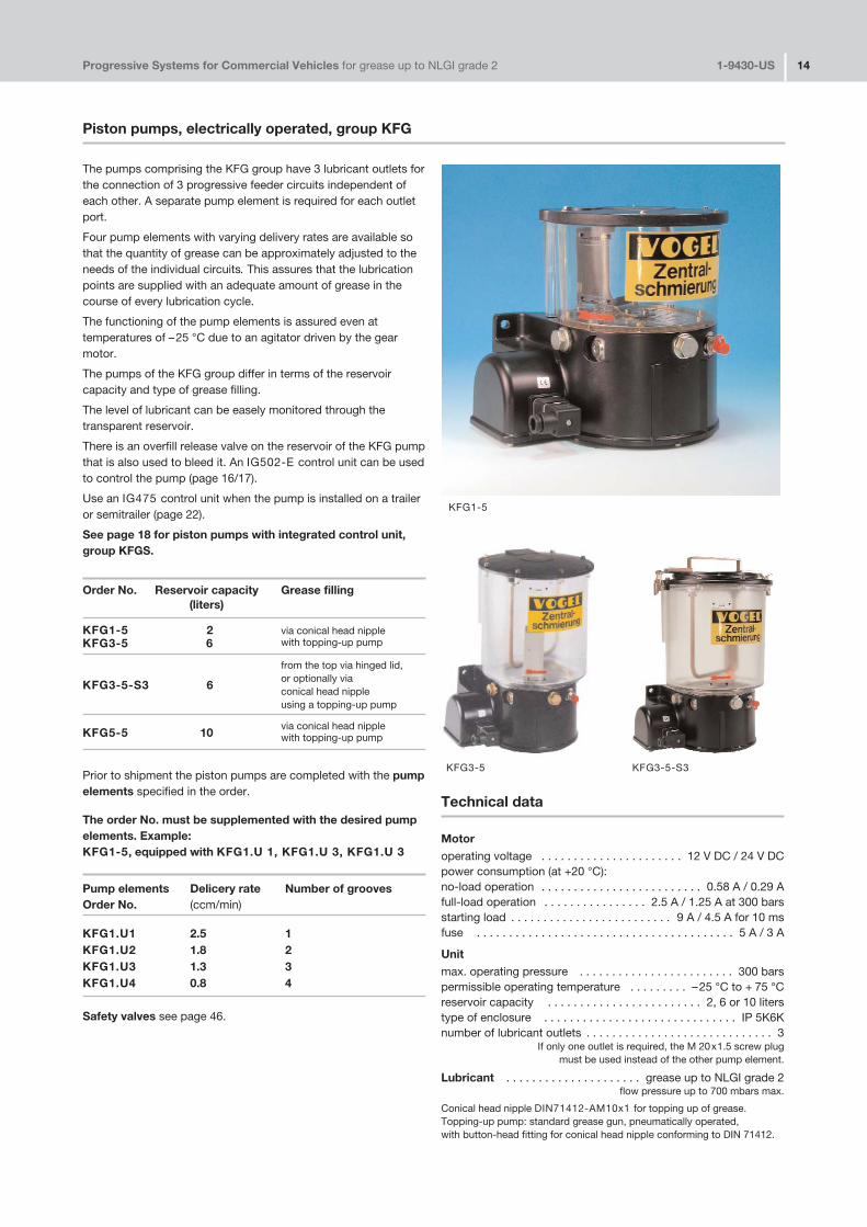
Piston pumps, electrically operated, group KFG
The pumps comprising the KFG group have 3 lubricant outlets forthe connection of 3 progressive feeder circuits independent ofeach other. A separate pump element is required for each outletport.
Four pump elements with varying delivery rates are available sothat the quantity of grease can be approximately adjusted to theneeds of the individual circuits. This assures that the lubricationpoints are supplied with an adequate amount of grease in thecourse of every lubrication cycle.
The functioning of the pump elements is assured even attemperatures of –25 °C due to an agitator driven by the gearmotor.
The pumps of the KFG group differ in terms of the reservoircapacity and type of grease filling.
The level of lubricant can be easely monitored through thetransparent reservoir.
There is an overfill release valve on the reservoir of the KFG pumpthat is also used to bleed it. An IG502�E control unit can be usedto control the pump (page 16/17).
Use an IG475 control unit when the pump is installed on a traileror semitrailer (page 22).
See page 18 for piston pumps with integrated control unit,group KFGS.
Order No. Reservoir capacity Grease filling(liters)
KFG1�5 2 via conical head nippleKFG3�5 6 with topping�up pump
from the top via hinged lid,
KFG3�5�S3 6or optionally viaconical head nippleusing a topping�up pump
KFG5�5 10via conical head nipplewith topping�up pump
Prior to shipment the piston pumps are completed with the pumpelements specified in the order.
The order No. must be supplemented with the desired pumpelements. Example:KFG1�5, equipped with KFG1.U 1, KFG1.U 3, KFG1.U 3
Pump elements Delicery rate Number of groovesOrder No. (ccm/min)
KFG1.U1 2.5 1KFG1.U2 1.8 2KFG1.U3 1.3 3KFG1.U4 0.8 4
Safety valves see page 46.
KFG1�5
KFG3�5 KFG3�5�S3
Technical data
Motoroperating voltage . . . . . . . . . . . . . . . . . . . . . . 12 V DC / 24 V DCpower consumption (at +20 °C):no�load operation . . . . . . . . . . . . . . . . . . . . . . . . . 0.58 A / 0.29 Afull�load operation . . . . . . . . . . . . . . . . 2.5 A / 1.25 A at 300 barsstarting load . . . . . . . . . . . . . . . . . . . . . . . . . 9 A / 4.5 A for 10 msfuse . . . . . . . . . . . . . . . . . . . . . . . . . . . . . . . . . . . . . . . . 5 A / 3 A
Unitmax. operating pressure . . . . . . . . . . . . . . . . . . . . . . . . 300 barspermissible operating temperature . . . . . . . . . –25 °C to + 75 °Creservoir capacity . . . . . . . . . . . . . . . . . . . . . . . . 2, 6 or 10 literstype of enclosure . . . . . . . . . . . . . . . . . . . . . . . . . . . . . . IP 5K6Knumber of lubricant outlets . . . . . . . . . . . . . . . . . . . . . . . . . . . . . 3
If only one outlet is required, the M 20x1.5 screw plugmust be used instead of the other pump element.
Lubricant . . . . . . . . . . . . . . . . . . . . . grease up to NLGI grade 2flow pressure up to 700 mbars max.
Conical head nipple DIN71412�AM10x1 for topping up of grease.Topping�up pump: standard grease gun, pneumatically operated,with button�head fitting for conical head nipple conforming to DIN 71412.

Progressive Systems for Commercial Vehicles for grease up to NLGI grade 2 1�9430�US 15
KFG1�5
KFG3�5
screw plug
line socketrotatable 4 x 90°
cable connection: + to 2– to 1
See above for missing dimensions and data
Hydraulic diagramtransparentreservoir
conical head nippleM10x1 (DIN 71412)
pump element
KFG3�5�S3
1) connection thread in pump housing2) return line port (normally closed)
1)
Progressive Systems for Commercial Vehicles for grease up to NLGI grade 2 1�9430�US 16
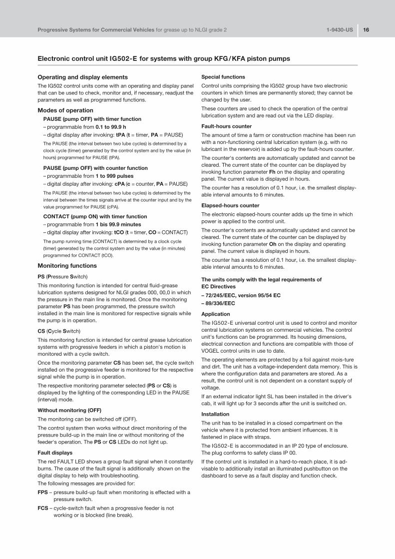
Operating and display elementsThe IG502 control units come with an operating and display panelthat can be used to check, monitor and, if necessary, readjust theparameters as well as programmed functions.
Modes of operationPAUSE (pump OFF) with timer function– programmable from 0.1 to 99.9 h– digital display after invoking: tPA (t = timer, PA = PAUSE)
The PAUSE (the interval between two lube cycles) is determined by a
clock cycle (timer) generated by the control system and by the value (in
hours) programmed for PAUSE (tPA).
PAUSE (pump OFF) with counter function– programmable from 1 to 999 pulses– digital display after invoking: cPA (c = counter, PA = PAUSE)
The PAUSE (the interval between two lube cycles) is determined by the
interval between the times signals arrive at the counter input and by the
value programmed for PAUSE (cPA).
CONTACT (pump ON) with timer function– programmable from 1 bis 99.9 minutes– digital display after invoking: tCO (t = timer, CO = CONTACT)
The pump running time (CONTACT) is determined by a clock cycle
(timer) generated by the control system and by the value (in minutes)
programmed for CONTACT (tCO).
Monitoring functions
PS (Pressure Switch)
This monitoring function is intended for central fluid�greaselubrication systems designed for NLGI grades 000, 00,0 in whichthe pressure in the main line is monitored. Once the monitoringparameter PS has been programmed, the pressure switchinstalled in the main line is monitored for respective signals whilethe pump is in operation.
CS (Cycle Switch)
This monitoring function is intended for central grease lubricationsystems with progressive feeders in which a piston's motion ismonitored with a cycle switch.
Once the monitoring parameter CS has been set, the cycle switchinstalled on the progressive feeder is monitored for the respectivesignal while the pump is in operation.
The respective monitoring parameter selected (PS or CS) isdisplayed by the lighting of the corresponding LED in the PAUSE(interval) mode.
Without monitoring (OFF)
The monitoring can be switched off (OFF).
The control system then works without direct monitoring of thepressure build�up in the main line or without monitoring of thefeeder's operation. The PS or CS LEDs do not light up.
Fault displays
The red FAULT LED shows a group fault signal when it constantlyburns. The cause of the fault signal is additionally shown on thedigital display to help with troubleshooting.
The following messages are provided for:
FPS – pressure build�up fault when monitoring is effected with apressure switch.
FCS – cycle�switch fault when a progressive feeder is notworking or is blocked (line break).
Special functions
Control units comprising the IG502 group have two electroniccounters in which times are permanently stored; they cannot bechanged by the user.
These counters are used to check the operation of the centrallubrication system and are read out via the LED display.
Fault�hours counter
The amount of time a farm or construction machine has been runwith a non�functioning central lubrication system (e.g. with nolubricant in the reservoir) is added up by the fault�hours counter.
The counter's contents are automatically updated and cannot becleared. The current state of the counter can be displayed byinvoking function parameter Fh on the display and operatingpanel. The current value is displayed in hours.
The counter has a resolution of 0.1 hour, i.e. the smallest display�able interval amounts to 6 minutes.
Elapsed�hours counter
The electronic elapsed�hours counter adds up the time in whichpower is applied to the control unit.
The counter's contents are automatically updated and cannot becleared. The current state of the counter can be displayed byinvoking function parameter Oh on the display and operatingpanel. The current value is displayed in hours.
The counter has a resolution of 0.1 hour, i.e. the smallest display�able interval amounts to 6 minutes.
The units comply with the legal requirements of EC Directives
– 72/245/EEC, version 95/54 EC– 89/336/EEC
Application
The IG502�E universal control unit is used to control and monitorcentral lubrication systems on commercial vehicles. The controlunit's functions can be programmed. Its housing dimensions,electrical connection and functions are compatible with those ofVOGEL control units in use to date.
The operating elements are protected by a foil against mois�tureand dirt. The unit has a voltage�independent data memory. This iswhere the configuration data and parameters are stored. As aresult, the control unit is not dependent on a constant supply ofvoltage.
If an external indicator light SL has been installed in the driver'scab, it will light up for 3 seconds after the unit is switched on.
Installation
The unit has to be installed in a closed compartment on thevehicle where it is protected from ambient influences. It isfastened in place with straps.
The IG502�E is accommodated in an IP 20 type of enclosure.The plug conforms to safety class IP 00.
If the control unit is installed in a hard�to�reach place, it is ad�visable to additionally install an illuminated pushbutton on thedashboard to serve as a fault display and function check.
Electronic control unit IG502�E for systems with group KFG/KFA piston pumps

Progressive Systems for Commercial Vehicles for grease up to NLGI grade 2 1�9430�US 17
Technical data
Order No. . . . . . . . . . . . . . . . . . . . . . . . . . . . . . . . . . . . IG502�E
Associated cable harness . . . . . . . . . order No. 997�000�185
control votlage 1) . . . . . . . . . . . . . . . . . . . . . . . . . . 12 or 24 V DCmax. contact load, terminal M . . . . . . . . . . . . . . . . . . . . . . . . 5 ASL�output . . . . . . . . . . . . . . . . . . . . . . . . . . . . . . . . . . . . . . . 4 Wtype of enclosure 2) . . . . . . . . . . . . . . . . . . . . . IP 20, DIN 40050temperature range . . . . . . . . . . . . . . . . . . . . . . . . –25 to +75 °Cmax. fusing. . . . . . . . . . . . . . . . . . . . . . . . . . . . . . . . . . . . . . . 5 Aprogrammable interval times . . . . . . . . . . . . . . . . . 0.1 to 99.9 hprogrammable pump running time . . . . . . . . . . . 0.1 to 99.9 minprogrammable pulses . . . . . . . . . . . . . . . . . . . . . . . . . . 1 to 999elapsed�time, fault hours memory . . . . . . . . . . . . 0 to 99999.9 h
1) Please quote control voltage when ordering.2) Warranted for vertical (plug�in connector pointing downward) and
horizontal installation.
Wiring diagram
(time axis not to scale)
tu = ignition interruptionts = contact timetp = interval time
30 = battery + / vehicle network15 = operating voltage + / after ignition “ON”31 = operating voltage –DK/MK = pushbutton / intermediate lubrication or pulse�counter inputPS/CS = pressure switch / cycle switch M = pump motorSL = indicator lightZ = ignition lockF = 5 A fuse
LED PAUSEllights in intervals.
LED CONTACTlights when pump running.
LED CSlights for monitoring with cycle switch function.
LED PSlights for monitoring with pressure switch function.
LED FAULTlights for fault monitoring (cycle or pressure switch).
Normal functional sequence
Progressive Systems for Commercial Vehicles for grease up to NLGI grade 2 1�9430�US 18
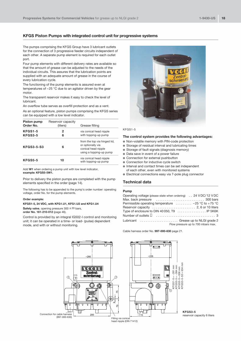
KFGS Piston Pumps with integrated control unit for progressive systems
The pumps comprising the KFGS Group have 3 lubricant outletsfor the connection of 3 progressive feeder circuits independent ofeach other. A separate pump element is required for each outletport.Four pump elements with different delivery rates are available sothat the amount of grease can be adjusted to the needs of theindividual circuits. This assures that the lubrication points aresupplied with an adequate amount of grease in the course ofevery lubrication cycle.The functioning of the pump elements is assured even attemperatures of –25 °C due to an agitator driven by the gearmotor.The transparent reservoir makes it easy to check the level oflubricant.An overflow tube serves as overfill protection and as a vent.
As an optional feature, piston pumps comprising the KFGS seriescan be equipped with a low level indicator.
Piston pump Reservoir capacity Order No. (liters) Grease filling
KFGS1�5 2 via conical head nippleKFGS3�5 6 with topping�up pump
from the top via hinged lid,
KFGS3�5�S3 6or optionally viaconical head nippleusing a topping�up pump
KFGS5�5 10via conical head nipplewith topping�up pump
Add W1 when ordering a pump unit with low level indicator, example: KFGS5�5W1.
Prior to delivery the piston pumps are completed with the pumpelements specified in the order (page 14).
The following has to be appended to the pump's order number: operatingvoltage, order No. for the pump elements.
Order example:
KFGS1�5, 24 VDC, with KFG1.U1, KFG1.U2 and KFG1.U4
Safety valve, opening pressure 300 ± 20 bars,order No. 161�210�012 (page 46).
Control is provided by an integral IG502�I control and monitoringunit; it can be operated in a time� or load� (pulse) dependentmode, and with or without monitoring.
The control system provides the following advantages:� Non�volatile memory with PIN�code protection� Storage of residual interval and lubricating times� Storage of fault signals (diagnosis memory)� Data save in event of a power failure� Connection for external pushbutton� Connection for inductive cycle switch� Interval and contact times can be set independent
of each other, even with monitored systems� Electrical connections easy via 7�pole plug connector
Technical data
PumpOperating voltage (please state when ordering) . . 24 V DC/12 V DCMax. back pressure . . . . . . . . . . . . . . . . . . . . . . . . . . . 300 barsPermissible operating temperature . . . . . . . . . –25 °C to +75 °CReservoir capacity . . . . . . . . . . . . . . . . . . . . . . . . 2, 6 or 10 litersType of enclosure to DIN 40 050, T9 . . . . . . . . . . . . . . . . IP 5K6KNumber of outlets ➀ . . . . . . . . . . . . . . . . . . . . . . . . . . . . . . . . . 3
Lubricant . . . . . . . . . . . . . . . . . . . . . Grease up to NLGI grade 2Flow pressure up to 700 mbars max.
Cable harness order No. 997�000�630 page 21.
KFGS1�5
KFGS3�5reservoir capacity 6 litersConnection for cable harness
(997�000�630) Filling via conical head nipple (DIN 71412)
KF
GS
1�5
= ~
281
mm
KF
GS
3�5
= ~
394
mm
KF
GS
5�5
= 6
36 m
mK
FG
S3
�5�S
3=
634
mm
IG502�I electronic control and monitoring unit integrated in KFGS and KFAS pump unit
General remarks
The IG502�I control and monitoring unit is an integral componentof KFGS and KFAS pump units. Its functions are speciallydesigned for the control and monitoring of central lubricationsystems on commercial vehicles (traveling machinery).
The control unit can be programmed by the customer to suit thevehicle's or machine's operating conditions and can be set forthe following modes of operation:
1. TIMER without monitoring
2. TIMER with monitoring
3. COUNTER without monitoring
4. COUNTER with monitoring
Interval (tPA) in the "TIMER" mode
The interval (pause between two lubrications) in the TIMER modeis determined by a clock cycle generated by the control systemand by the value programmed as tPA. It can be set for a valuebetween 0.1 and 99.9 h.
Interval (cPA) in the "COUNTER" mode
The interval (pause between two lubrication routines) in theCOUNTER mode is determined by the interval between pulsesarriving at input "DK" (signal change from 0 V to 24 V) and by thevalue programmed as cPA. It can be set for a value from 1 to 999pulses. In this mode terminal "DK" leading out of the unit is usedas a counter input in order to trigger lubrication after a definednumber of pulses. In this case, there is no possibility to press anexternal pushbutton to trigger intermediate lubrication.
Setting of the interval and pump running times as well asdesired monitoring function
The operations required to set the control unit for the values andfunctions in line with the vehicles' use can be found in theoperating instructions included with the pump unit.
Function (standard "TIMER" function without monitoring)
The lubrication periods are repeated on a cyclic basis at the rateof the selected interval (tPA or cPA). The pump running timeduring a lubrication routine corresponds to the time in minutesset on the control panel as tCO (contact time).
The intervals as well as the pump running times are executedonly when the power is on (terminals 15 and 31 connected to 12VDC or 24 VDC, depending on the unit). If the power is switchedoff (interruption of the voltage to terminal 15), the currentlyrunning residual time is stored and continued after the power isswitched on again.
If the monitoring function "CS" is programmed (only for centrallubrication systems with cycle switches), the cycle switchmounted on a progressive feeder is queried for the emittance of asignal while the pump is running. At least one signal change(either ON>OFF or OFF>ON) is expected from the control routineat terminal ZDS in the cable harness in order for a new interval tostart at the end of the pump's running time and for the sequenceof functions to continue normally. If this signal fails to materializeduring the preset pump running time (tCO), a monitoring program(block mode) is started at the end of that period. In this programroutine the pump unit is additionally switched on at speciallydefined intervals up to a maximum of two times and the cycle
switch is monitored for the emittance of a signal. When the cycleswitch signal arrives at the control unit, the monitoring program isimmediately ended and operation with the normal sequence offunctions is continued. When the monitoring program elapses, afault signal is admitted at the end and the functional sequencestopped.
No intermediate lubrication can be triggered while the monitoringprogram is running.
Memory (EEPROM)
The control system comes with a non�volatile memory(EEPROM), so a constant supply of power is not required for thestorage of residual times and fault signals. When the power isswitched off (ignition), the current value is stored and is availablefor the further sequence of functions after the power returns.
Monitoring and fault displays
Function monitoring with cycle switch
Central lubrication systems can be monitored with cycleswitches. For this to be done, the unit has to be set(programmed) under "COP" for "CS" monitoring (cycle switch).The signal emitted by the switch during the lubrication routine isthen monitored.
If no signal is emitted during both the lubrication routine and themonitoring program automatically started thereafter, a fault signalis emitted at the end of the monitoring program (terminal "SL2" isconstantly on) and the functional sequence is interrupted. The"FCS" error code (Fault Cycle Switch) can be invoked by pressinga button on the control panel.
Monitoring of filling level
KFGS and KFAS pump units with the identifier "W1" in the ordernumber come from the factory with integrated filling�levelmonitoring that is always active and does not have to beprogrammed
When the minimal filling level is reached, a fault display is shown(terminal "SL2" is constantly on) and the functional sequence isinterrupted. The "FLL" fault code (Fault Low�Level) can beinvoked by pressing a button on the control panel.
Clearing a fault message
No signal change at ZDS input � this fault signal can be clearedwhile the power is on by pressing pushbutton DK.
Filling level fault � this fault signal can be cleared when the poweris on after the reservoir has been filled by pressing pushbuttonDK.
Elapsed�hours counter
The control unit comes with a built�in elapsed�hours counterwhich adds up the time in which power is applied to the controlunit. The memory cannot be changed. The stored values can becalled up on the control panel and viewed.
Fault�hours memory
The control unit comes with a fault�hours memory that adds upthe time in which the control unit was operated with a pendingfault signal. The memory cannot be changed. The stored valuescan be called up on the control panel and viewed.
Progressive Systems for Commercial Vehicles for grease up to NLGI grade 2 1�9430�US 19

Progressive Systems for Commercial Vehicles for grease up to NLGI grade 2 1�9430�US 20
KFA/KFAS Mini�Pump Units with integral control system
Pumps belonging to the KFA(S) series come with a maximum of 2outlet ports for the connection of 2 independent lube circuits. Aseparate pump element is required for each outlet.
Three pump elements with different delivery rates are available sothat the volume of grease can be adjusted to the needs of theindividual circuits. That makes sure every lube point is suppliedwith an adequate amount of grease in each lubrication cycle.
Piston pump Reservoir capacity Order No. (liters) Grease filling
KFA1 1 via conical head nippleKFAS1 (incl. control system) 1 via topping�up pump
A “W” has to be appended to the order No. for pump units with fillinglevel monitoring, order example: KFAS1�W.
Pump elements Delivery rate 1)Order No. (ccm/min)
KFA1.U1 2.0KFA1.U2 1.5KFA1.U3 1.0
The following has to be appended to the pump's order number: operating voltage, order No. for the pump elements.
Order example:
KFAS1, 12 V DC with KFA1.U2, KFA1.U3
1) The indicated rates refer to the delivery of NLGI grade 2 grease at anoperating temperature of 20°C and a back pressure of 50 bars.
Temperatures and pressures that deviate from these figures lead todifferent delivery rates. The indicated values must be taken as a basis inthe design of a central lubrication system.
Technical Data
Unit
operating voltage . . . . . . . . . . . . . . . . . . . . . . 12 VDC / 24 VDC(please indicate when ordering)
Mode/ON time . . . . . . . . . . . . . . . . . . . . . . . . S3/20% � 50 min.Pay attention to interval and contact time when setting!
Max. runtime 10 min., interval time = 4 x runtime
max. back pressure . . . . . . . . . . . . . . . . . . . . . . . . . . . . 300 barspermissible operating temperature . . . . . . . . . –25 °C to +75 °Creservoir capacity . . . . . . . . . . . . . . . . . . . . . . . . . . . . . . . . 1 literDIN 40050 enclosure, T9 . . . . . . . . . . . . . . . . . . . . . . . . IP 6K9Kmax. number of outlets . . . . . . . . . . . . . . . . . . . . . . . . . . . . . . . 2weight (filled with grease) . . . . . . . . . . . . . . . . . . . approx. 3.8 kglubricant . . . . . . . . . . . . . . . . . . . . . . grease up to NLGI grade 2
flow pressure up to max. 700 mbars
Compliant with the legal requirements of EC directives:– 72/245/EEC, version 95/54 EC– 89/336/EEC
Control is provided by an integral IG502�I control and monitoringunit; it can be operated in a time� or load� (pulse) dependentmode, and with or without monitoring (page 19).
The control system provides the following advantages:
� Non�volatile memory with PIN�code protection� Storage of residual interval and lubricating cycle� Storage of fault signals (diagnosis memory)� Data save in event of a power failure� Connection for external pushbutton� Connection for inductive cycle switch� Interval and contact times can be set independent
of each other, even with monitored systems� Electrical connections easy via 7�pole plug connector
Cable harness please order separately (page 21 and 37).
Safety valves page 46.
KFAS1
Progressive Systems for Commercial Vehicles for grease up to NLGI grade 2 1�9430�US 21
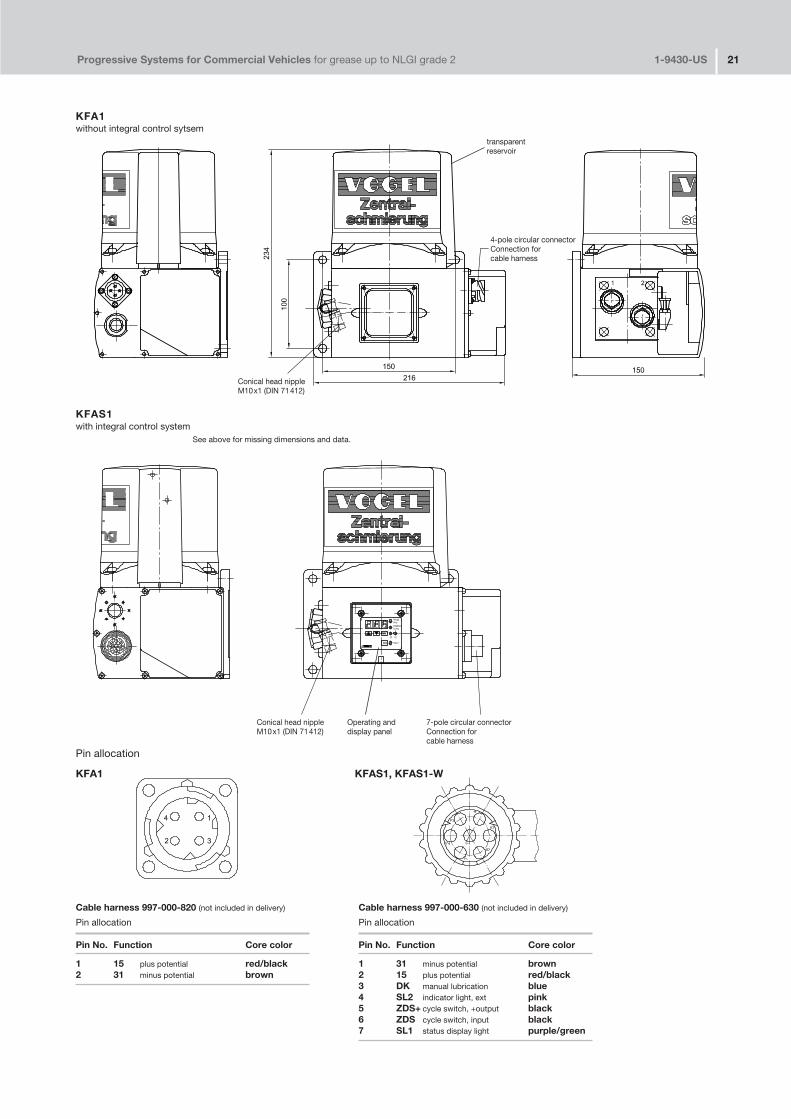
KFA1without integral control sytsem
Cable harness 997�000�630 (not included in delivery)
Pin allocation
Pin No. Function Core color
1 31 minus potential brown2 15 plus potential red/black3 DK manual lubrication blue4 SL2 indicator light, ext pink5 ZDS+ cycle switch, +output black6 ZDS cycle switch, input black7 SL1 status display light purple/green
Cable harness 997�000�820 (not included in delivery)
Pin allocation
Pin No. Function Core color
1 15 plus potential red/black2 31 minus potential brown
KFAS1with integral control system
See above for missing dimensions and data.
transparent reservoir
Conical head nippleM10x1 (DIN 71412)
Conical head nippleM10x1 (DIN 71412)
4�pole circular connector Connection for cable harness
7�pole circular connectorConnection for cable harness
Operating anddisplay panel
Pin allocation
KFA1 KFAS1, KFAS1�W
Progressivanlagen für Nutzfahrzeuge für Fett bis NLGI�Klasse 2 1�9430 22
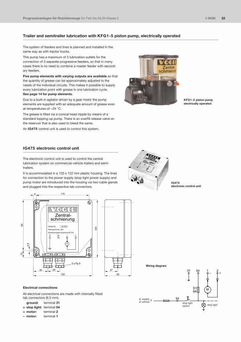
Trailer and semitrailer lubrication with KFG1�5 piston pump, electrically operated
The system of feeders and lines is planned and installed in thesame way as with tractor trucks.
This pump has a maximum of 3 lubrication outlets for theconnection of 3 separate progressive feeders, so that in manycases there is no need to combine a master feeder with second�ary feeders.
Five pump elements with varying outputs are available so thatthe quantity of grease can be approximately adjusted to theneeds of the individual circuits. This makes it possible to supplyevery lubrication point with grease in one lubrication cycle.See page 14 for pump elements.
Due to a built�in agitator driven by a gear motor the pumpelements are supplied with an adequate amount of grease evenat temperatures of –25 °C.
The grease is filled via a conical head nipple by means of astandard topping�up pump. There is an overfill release valve onthe reservoir that is also used to bleed the same.
An IG475 control unit is used to control this system.
IG475 electronic control unit
The electronic control unit is used to control the centrallubrication system on commercial�vehicle trailers and semi�trailers.
It is accommodated in a 120 x 122 mm plastic housing. The linesfor connection to the power supply (stop light power supply) andpump motor are introduced into the housing via two cable glandsand plugged into the respective tab connectors.
Electrical connections
All electrical connections are made with internally fitted tab connectors (6.3 mm).
ground: terminal 31+ stop light: terminal 54+ motor: terminal 2– motor: terminal 1
IG475electronic control unit
KFG1�5 piston pumpelectrically operated
el. supplyof vehicle stop light
switch stop light
Wiring diagram

Functional sequence
The operating voltage is tapped from the stop light signal. Thismeans voltage is fed to the control unit via the stop light switchonly when the brakes are applied. The pump unit is only switchedon after a fixed delay time tV in order to keep the making currentas small as possible when the brakes are applied. This assuresthat the making current of the stop lights has already decayedwhen the pump motor starts.
The preset lubricating time tS begins when the pump unit isswitched on. But the pump unit only runs as long as the brakesare applied and the lubricating time has not yet expired. If thebraking is briefly interrupted during the lubricating time (for lessthan the recovery time tW [5 sec.]), the remaining lubricating timein the memory runs down when the brakes are applied again andafter expiration of the delay time tV. The recovery time alreadyexpired is cleared.
If braking is interrupted longer than the recovery time, renewedbraking triggers new lubrication at the end of the delay time. Anyremaining lubricating times in the memory are cleared.
The automatic time function is deactivated when switch S1 is setto position D. The pump unit is switched on when the operatingvoltage is applied and after the delay time tV expires. It remainson as long as the operating voltage is applied. This position canbe used, for example, to fill the lines when the central lubricationsystem is started up the first time.
Progressivanlagen für Nutzfahrzeuge für Fett bis NLGI�Klasse 2 1�9430 23
Circuit board
Preselection of pump running time
The pump running time can be set for 2, 4 or 8 seconds on thecircuit board with a plug�in jumper. The time is set for 2 secondsat the factory.
A switch marked S1 on the circuit board is used to switch overfrom automatic to continuous lubrication. Position D is forcontinuous operation and position Z for automatic lubrication.
Technical data
Order No. . . . . . . . . . . . . . . . . . . . . . . . . . . . . . IG475control voltage 1) . . . . . . . . . . . . . . . . . 24 or 12 V DCbreaking capacity . . . . . . . . output + motor (terminal 2) at 24 V DC: 10 A . . . . . . . . . . . . . . . . . . . . . . . . . . . . . . at 12 V DC: 15 Aoperate delay . . . . . . . . . . . . . . . . . . 0.75 sec. ± 30 %lubricating time . . . . . . . . . . . . . 2 sec., 4 sec., 8 sec.recovery time . . . . . . . . . . . . . . . . . . . . 5 sec. ± 10 %rated consumption without motor . .at 12 V DC: ≈ 2 W . . . . . . . . . . . . . . . . . . . . . . . . . . . . .at 24 V DC: ≈1.5 Wtype of enclosure . . . . . . . . . . . . . . . . . . . . . . . . IP 65operating temperature . . . . . . . . . . . . . –25 to +75 °C
1) Please state control voltage when ordering.
tV: operate delay of lubricating timetA: time in which battery voltage is not appliedtW: recovery time
for clearing of stored lubricating timetS: preselected lubricating timet1 and t2 = tSt3 = < tS
Functional sequence diagrams
lubricating timeswitching relay
operating voltagebrake switch +54
operating voltagebrake switch +54
lubricating timeswitching relay
Switch S1 set to D
The recovery time tw is initiated after every downward edge of thebattery voltage
Switch S1 set to Z
plug�in jumpers
lubricating time2 sec., 4 sec., 8 sec.
switch
automatictime function = Zcontinuous operation = D
tab connectorterminals
2s
4s
8s
• •
• •
Z D
3 1 2S1
54 (+)
31 (–)
2 (+)
1 (–)
II I I I

Progressive Systems for Commercial Vehicles for grease up to NLGI grade 2 1�9430�US 24
Progressive feeders, groups VPM, VPKM
In the case of systems for NLGI grade 2 grease the lubricant isdistributed by way of progressive feeders.
Progressive feeders are available for use on commercial vehiclesin three groups that differ not only in size but also in design.
A section�type progressive feeder consists of at least threesections to a maximum of ten. In each feeder section there is onepiston for the apportioning and delivery of the lubricant. Thepiston diameter and piston path determine the delivery rate perstroke. Each piston has two tasks, first delivering and secondcontrolling, i.e. it can deliver its lubricant only after the precedingone has discharged its lubricant. This makes it relatively simple tomonitor lubricant delivery. It is sufficient to monitor only themotion of the piston in one single section to be sure that theprogressive feeder is still working.
The lubricant quantity supplied by the pump is apportioned In theprogressive feeder to the individual lubrication points in keepingwith the metered quantity of the individual sections.
The delivery rate in ccm and length of the cycle (pump runningtime) determine the absolute quantity fed to the individual lubri�cation points. The pistons of the progressive feeders execute oneor more strokes in this connection.
Important!
Progressive�feeder outlets that are not required must not beplugged. Instead, these outlets must either be combined with anadjacent outlet, i.e. fed to a lubrication point, or connected to thepump via a return line.
When monitored systems are involved, one feeder section mustbe provided with a cycle switch. In the case of section�typefeeders this cycle switch has to installed on a PS section orordered together with the progressive feeder, cf. page 27. Later installation of a cycle switch is possible only on PSsections.
In Fig. 1 piston side 4 is pressurized by the pump, piston side 1has delivered lubricant to outlet 1a. The connection between themain line and piston side 5 has become free due to the stroke ofpiston 1/4.
In Fig. 2 piston side 5 is pressurized and piston side 2 delivers thelubricant via outlet 2a. Piston side 6 is the next to be pressurized,etc.
Fig. 1 Fig. 2
lubricantinlet �
lubricantinlet �
Function

Progressive Systems for Commercial Vehicles for grease up to NLGI grade 2 1�9430�US 25
Progressive feeders, group VPM
In the case of this group the feeder sections have two outlets oneach side, one each on the side and one on top, but only onemay be used. The second outlet must always be kept closed.These feeders are supplied with a built�in check valve.
A later combination of two outlets is only possible with a crossporting bar that is screwed into the upper alternative outlets.Any odd number of outlets can be achieved with the help of S�sections without additional crossporting bars.
Operating pressure: 10 bars min. / 250 bars max.
Number of Number ofOrder No. feeder sections possible outlets L1 1) L2
VPM�3 3 6 84 98VPM�4 4 8 104 118VPM�5 5 10 124 138VPM�6 6 12 144 158VPM�7 7 14 164 178VPM�8 8 16 184 198VPM�9 9 18 204 218VPM�10 10 20 224 238
ApportionmentSelection of feeder sections for the desired lubricant quantity
Amount per cycle Number of Designationand outlet (ccm) outlets of sections
0.05 2 1T0.14 2 2T0.19 2 3T0.25 2 4T0.3 2 5T0.35 2 6T0.1 1 1S *0.28 1 2S *0.38 1 3S *0.5 1 4S *0.6 1 5S *0.7 1 6S *
All PS sections can be outfitted with a cycle switch.
*) The two outlets of one feeder section are combined here.
Straight connectors
for inlet M14x1.5: for 6 mm diam. tube, order No. 406�413for 10 mm diam. tube, order No. 410�403
for outlets M10x1: for 4 mm diam. tube, order No. 404�006Kfor 6 mm diam. tube, order No. 406�423
or corresponding plug�in connectors
1) The spacing between holes for attachment of the feeders can deviatefrom the indicated dimensions due to the individual tolerances of thefeeder sections.It is therefore advisable to drill the attachment holes on the mountingsurface.
Crossporting bar
The crossporting bar is used to combine the lubricant outputs oftwo adjacent feeder sections via the alternative outlets on top ofthe feeder.
Order No. VP�C
Model: complete with banjo bolts and washers.
Crossporting bar
feeder sections
lubricantoutlets
Screw plug incl O�ring 466�431�001
lubricant �inlet
inlet section
If “outlet on top”,screw top plug in on the side
end section
Progressive Systems for Commercial Vehicles for grease up to NLGI grade 2 1�9430�US 26
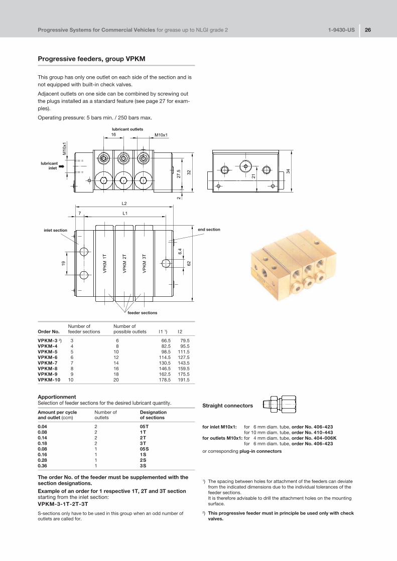
Progressive feeders, group VPKM
This group has only one outlet on each side of the section and isnot equipped with built�in check valves.
Adjacent outlets on one side can be combined by screwing outthe plugs installed as a standard feature (see page 27 for exam�ples).
Operating pressure: 5 bars min. / 250 bars max.
Straight connectors
for inlet M10x1: for 6 mm diam. tube, order No. 406�423for 10 mm diam. tube, order No. 410�443
for outlets M10x1: for 4 mm diam. tube, order No. 404�006Kfor 6 mm diam. tube, order No. 406�423
or corresponding plug�in connectors
1) The spacing between holes for attachment of the feeders can deviatefrom the indicated dimensions due to the individual tolerances of thefeeder sections.It is therefore advisable to drill the attachment holes on the mountingsurface.
2) This progressive feeder must in principle be used only with checkvalves.
Number of Number ofOrder No. feeder sections possible outlets l1 1) l 2
VPKM�3 2) 3 6 66.5 79.5VPKM�4 4 8 82.5 95.5VPKM�5 5 10 98.5 111.5VPKM�6 6 12 114.5 127.5VPKM�7 7 14 130.5 143.5VPKM�8 8 16 146.5 159.5VPKM�9 9 18 162.5 175.5VPKM�10 10 20 178.5 191.5
ApportionmentSelection of feeder sections for the desired lubricant quantity.
Amount per cycle Number of Designationand outlet (ccm) outlets of sections
0.04 2 05T0.08 2 1T0.14 2 2T0.18 2 3T0.08 1 05S0.16 1 1S0.28 1 2S0.36 1 3S
The order No. of the feeder must be supplemented with thesection designations.Example of an order for 1 respective 1T, 2T and 3T sectionstarting from the inlet section:VPKM�3�1T�2T�3T
S�sections only have to be used in this group when an odd number ofoutlets are called for.
lubricant �inlet
lubricant outlets
inlet section end section
feeder sections
Progressive Systems for Commercial Vehicles for grease up to NLGI grade 2 1�9430�US 27
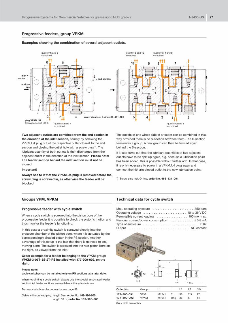
Progressive feeders, group VPKM
Examples showing the combination of several adjacent outlets.
Two adjacent outlets are combined from the end section inthe direction of the inlet section, namely by screwing theVPKM.U4 plug out of the respective outlet closest to the endsection and closing the outlet hole with a screw plug 1). Thelubricant quantity of both outlets is then discharged from theadjacent outlet in the direction of the inlet section. Please note!The feeder section behind the inlet section must not beclosed!
Important!
Always see to it that the VPKM.U4 plug is removed before thescrew plug is screwed in, as otherwise the feeder will beblocked.
The outlets of one whole side of a feeder can be combined in thisway provided there is no S�section between them. The S�sectionterminates a group. A new group can then be formed againbehind the S�section.
If it later turns out that the lubricant quantities of two adjacentoutlets have to be split up again, e.g. because a lubrication pointhas been added, this is possible without further ado. In that case,it is only necessary to screw in a VPKM.U4 plug again andconnect the hitherto closed outlet to the new lubrication point.
1) Screw plug incl. O�ring, order No. 466�431�001
Groups VPM, VPKM
Progressive feeder with cycle switch
When a cycle switch is screwed into the piston bore of theprogressive feeder it is possible to check the piston's motion andthus monitor the feeder's functioning.
In this case a proximity switch is screwed directly into thepressure chamber of the piston bore, where it is actuated by thecorrespondingly shaped piston in the PS section. Anotheradvantage of this setup is the fact that there is no need to sealmoving parts. The switch is screwed into the rear piston bore onthe right, as viewed from the inlet.
Order example for a feeder belonging to the VPKM group:VPKM�3�05T�3S�2T�PS installed with 177�300�092, on theright.
Please note:cycle switches can be installed only on PS sections at a later date.
When retrofitting a cycle switch, always use the special associated feedersection! All feeder sections are available with cycle switches.
For associated circular connector see page 38.
Cable with screwed plug, length 5 m, order No. 169�990�600length 10 m, order No. 169�990�603
Technical data for cycle switch
Max. operating pressure . . . . . . . . . . . . . . . . . . . . . . . . 350 barsOperating voltage . . . . . . . . . . . . . . . . . . . . . . . . . 10 to 36 V DCPermissible current loading . . . . . . . . . . . . . . . . . . 100 mA max.Residual current/power consumption . . . . . . . . . . . . . . ≤ 0.8 mAType of enclosure . . . . . . . . . . . . . . . . . . . . . . . . . . . . . . . . IP 67Output . . . . . . . . . . . . . . . . . . . . . . . . . . . . . . . . . . . . NC contact
Order No. Group d1 L L1 L2 SW
177�300�091 VPM M12x1 61 38 7.5 17177�300�092 VPKM M10x1 59.5 36 6 14
end section
quantity 5 and 6combined
quantity 2 and 4combined
plug VPKM.U4(hexagon socket SW3)
screw plug incl. O�ring 466�431�001
inletsection
lubricantinlet
quantity 2 and 6combined
quantity 9 and 10combined
quantity 3, 7 and 8combined
LED
SW = width across flats

Progressive Systems for Commercial Vehicles for grease up to NLGI grade 2 1�9430�US 28
Progressive feeder, group VPBM
Features:
�� Block�type design, smallest feeder group, used mainly forgrease�lubricated machines and equipment.
�� Uniform metering: 0.13 ccm.
�� Two outlets opposite each other can be connected at alater date by screwing out the plug in the outlet on the right(outlet ports on top as viewed from the lubricant inlet) andclosing one of the two outlets.
�� Two or more adjacent outlets are combined with externalcrossporting bars.
�� Without built�in check valves.
�� Without alternative outlets.
operating pressure: 5 bars min. / 400 bars max.
Number of Number of LOrder No. outlet pairs (pistons) maximum outlets (mm)
VPBM�3 1) 3 6 60VPBM�4 4 8 75VPBM�5 5 10 90VPBM�6 6 12 105VPBM�7 7 14 120VPBM�8 8 16 135VPBM�9 9 18 150VPBM�10 10 20 165
1) This progressive feeder must in principle be used only with checkvalve VPKM�RV�S4.
VPBM�3shown withoutlet ports on top
lubricantinlet
lubricant outlets
lubricantinlet
plug VPKM.U4(hexagon socket SW 3)
plug VPKM.U4(hexagon socket SW3)
Straightconnectors
for inlet M10x1:for 6 mm diam. tube, order No. 406�423for 10 mm diam. tube, order No. 410�443
for outlets M10x1:for 4 mm diam. tube, order No. 404�006Kfor 6 mm diam. tube, order No. 406�423
or corresponding plug�in connectors
Function diagram
screw plug incl. O�ring466�431�001
�
�
SW = width across flats

Progressive Systems for Commercial Vehicles for grease up to NLGI grade 2 1�9430�US 29
Prosgressive feeder, group VPBM
Cycle switch for VPBMin order to monitor the stroke of the piston.
This switch can be screwed into any cylinder bore since it isactuated directly by the piston.
The cycle switch can be ordered separately for laterinstallation or complete with feeder.
Cycle switch: Order No. 177�300�096
Progressive feeder with cycle switch:
Order example: VPBM�3 mounted with 177�300�096, right
The cycle switch is then installed in the rear, right�hand bore ofthe feeder as viewed from the inlet.
For the associated circular connector see page 38.
See page 27 for technical data.
Cable with screwed plug, length 5 m, order No. 169�990�600length 10 m, order No. 169�990�603
Crossporting bars for the connection of adjacent outlets
Number of Order No. Order No.outlets to be of complete crossporting of complete crossportingconnected bar including banjo bolts and bar including banjo bolts and
adapter for 6 mm diam. tube adapter for 6 mm diam. tubeand check valve
2 VPBM�C2 VPBM�C3 VPBM�C3 –4 VPBM�C4 –
Check valvefor direct installation in a feeder outlet.
Order No. VPKM�RV�S4 6 mm diam tube connector
direction of flow �
177�300�096
VPBM�C3
VPBM�C
VPKM�RV�S4
LED
SW = width across flats
Progressive Systems for Commercial Vehicles for grease up to NLGI grade 2 1�9430�US 30
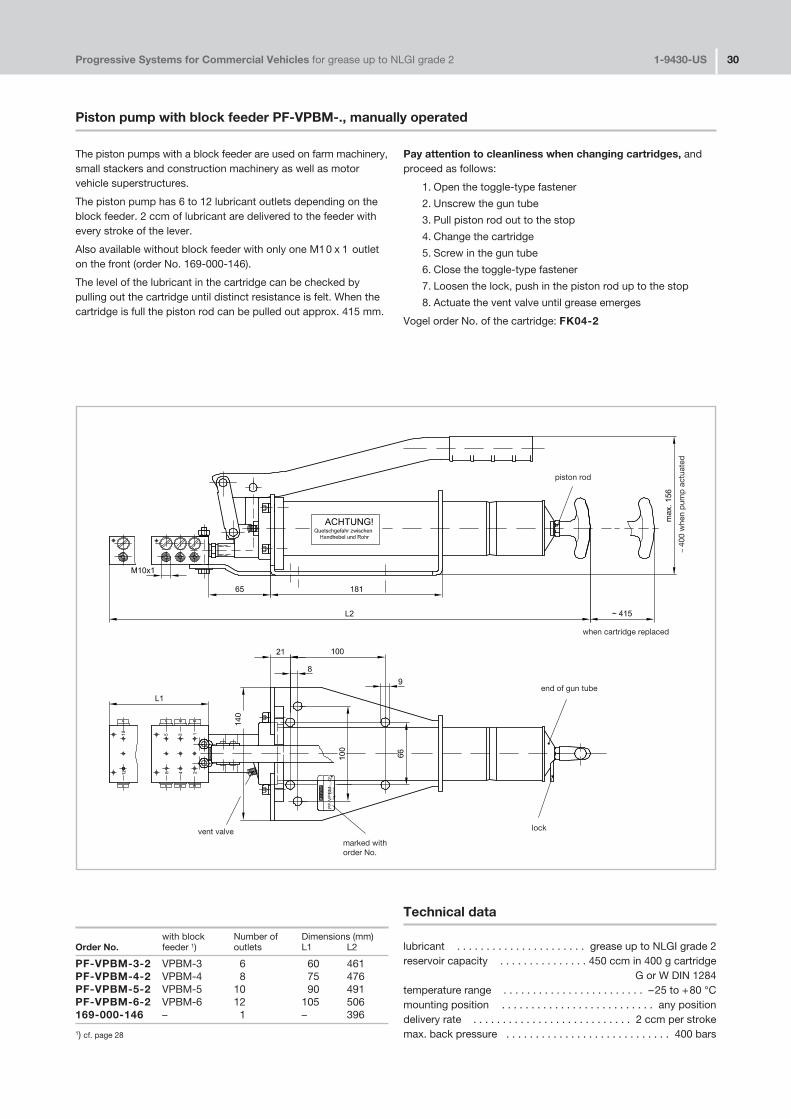
Piston pump with block feeder PF�VPBM�., manually operated
The piston pumps with a block feeder are used on farm machinery,small stackers and construction machinery as well as motorvehicle superstructures.
The piston pump has 6 to 12 lubricant outlets depending on theblock feeder. 2 ccm of lubricant are delivered to the feeder withevery stroke of the lever.
Also available without block feeder with only one M10 x 1 outleton the front (order No. 169�000�146).
The level of the lubricant in the cartridge can be checked bypulling out the cartridge until distinct resistance is felt. When thecartridge is full the piston rod can be pulled out approx. 415 mm.
Pay attention to cleanliness when changing cartridges, andproceed as follows:
1. Open the toggle�type fastener
2. Unscrew the gun tube
3. Pull piston rod out to the stop
4. Change the cartridge
5. Screw in the gun tube
6. Close the toggle�type fastener
7. Loosen the lock, push in the piston rod up to the stop
8. Actuate the vent valve until grease emerges
Vogel order No. of the cartridge: FK04�2
with block Number of Dimensions (mm)Order No. feeder 1) outlets L1 L2
PF�VPBM�3�2 VPBM�3 6 60 461PF�VPBM�4�2 VPBM�4 8 75 476PF�VPBM�5�2 VPBM�5 10 90 491PF�VPBM�6�2 VPBM�6 12 105 506169�000�146 – 1 – 396
1) cf. page 28
Technical data
lubricant . . . . . . . . . . . . . . . . . . . . . . grease up to NLGI grade 2reservoir capacity . . . . . . . . . . . . . . . 450 ccm in 400 g cartridge
G or W DIN 1284temperature range . . . . . . . . . . . . . . . . . . . . . . . . –25 to +80 °Cmounting position . . . . . . . . . . . . . . . . . . . . . . . . . . any positiondelivery rate . . . . . . . . . . . . . . . . . . . . . . . . . . . 2 ccm per strokemax. back pressure . . . . . . . . . . . . . . . . . . . . . . . . . . . . 400 bars
vent valve
end of gun tube
piston rod
when cartridge replaced
lock
~40
0 w
hen
pum
p a
ctua
ted
marked with order No.

Progressive Systems for Commercial Vehicles for grease up to NLGI grade 2 1�9430�US 31
Premetering unit
Order No. Output in ccm Operating pressure in bars
VF�20 20 100�350VF�40 40
Lubricating aid (single grease�fitting lubrication)
a) with premetering unitb) without premetering unit
All the lubrication points of the chassis (with the exceptionof those on the cardan shaft) can be combined by meansof progressive feeders to form a system with a singlegrease fitting. The lubricating times are kept to a mini�mum, and no lubrication point can be forgotten.
a) We recommend that the system be operated with apremetering unit.The quantity of lubricant delivered by a standard greasegun in the shop is fed to the progressive feeders afterbeing limited to either 20 or 40 ccm by the premeteringunit. From there it goes to the lubrication points. Keepthe grease gun pressed to the nipple until the functiondisplay on the premetering unit has reached its fullthrow. The function display slowly returns to its initialposition after the grease gun is removed, and a smallamount of grease emerges from the nipple of thepremetering unit (discharge volume).
Please note: The lubrication nipple on the premeteringunit does not contain a check valve to ensure renewedcharging of the unit.
b) The same system with progressive feeders, but withouta premetering unit to limit the volume, and thusindirectly the pressure, can be reliably operated only if itis ensured
1. that the pump pressure does not exceed 100 barsor
2. that flexible high�pressure hoses are used for non�stationary lubrication points.
Operate the drum pump or grease gun until grease canbe seen to emerge at the friction points. Locate thelubrication nipple at an easily accessible place.
The grease fed to the individual lubrication points is notmetered out, but only portioned out; i.e. the totalamount of lubricant fed to all the lubrication points is upto the operator. Only the proportional distribution of thisquantity is determined by the choice of the meteredfeeder quantities.
The systems described in point a) have the followingadvantages:
1. The pump, lubricant reservoir and control unit can bedispensed with on the vehicle.
2. Metered apportionment of lubricant; thus savings ongrease.
Any grease gun, even one producing a pressure of 400bars, can be used without risk. Furthermore, the use offlexible high�pressure hoses will only be necessary inexceptional cases.
If changes in trucking operations or the shop staff make itappear advisable, both systems – with or without a pre�metering unit – can easily be supplemented by a pump,reservoir and control unit of the vehicle's own. The feedersand tubing, i.e. the entire system, remain unchanged.
Please note! Clean lubrication nipple!Use clean grease gun!Fouling risk!
Central lubrication system with premetering unit(central single grease�fitting lubrication
lubrication points
master feeder
tube connectorwith lubrication nipple
pin forfunction display
premetering unit
drum pumpwith grease gun
indicator pinbeneathprotective cover
adapter for10 mm diam. tube
lubrication nippleacc. to DIN 71 412
b) or a)
nipple forgrease gun
Progressive Systems for Commercial Vehicles for grease up to NLGI grade 2 1�9430�US 32
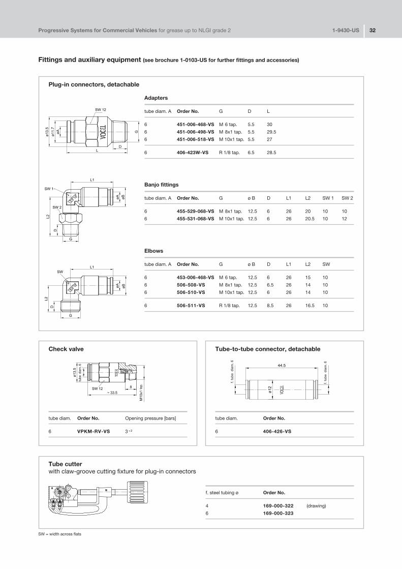
Fittings and auxiliary equipment (see brochure 1�0103�US for further fittings and accessories)
Plug�in connectors, detachable
Adapters
tube diam. A Order No. G D L
6 451�006�468�VS M 6 tap. 5.5 30
6 451�006�498�VS M 8x1 tap. 5.5 29.5
6 451�006�518�VS M 10x1 tap. 5.5 27
6 406�423W�VS R 1/8 tap. 6.5 28.5
Banjo fittings
tube diam. A Order No. G ø B D L1 L2 SW 1 SW 2
6 455�529�068�VS M 8x1 tap. 12.5 6 26 20 10 10
6 455�531�068�VS M 10x1 tap. 12.5 6 26 20.5 10 12
Elbows
tube diam. A Order No. G ø B D L1 L2 SW
6 453�006�468�VS M 6 tap. 12.5 6 26 15 10
6 506�508�VS M 8x1 tap. 12.5 6.5 26 14 10
6 506�510�VS M 10x1 tap. 12.5 6 26 14 10
6 506�511�VS R 1/8 tap. 12.5 8.5 26 16.5 10
Check valve
tube diam. Order No. Opening pressure [bars]
6 VPKM�RV�VS 3 +2
Tube�to�tube connector, detachable
tube diam. Order No.
6 406�426�VS
Tube cutterwith claw�groove cutting fixture for plug�in connectors
f. steel tubing ø Order No.
4 169�000�322 (drawing)
6 169�000�323
tube
dia
m. 6
f. tu
be
dia
m. 6
f. tu
be
dia
m. 6
tap.
SW = width across flats
Progressive Systems for Commercial Vehicles for grease up to NLGI grade 2 1�9430�US 33
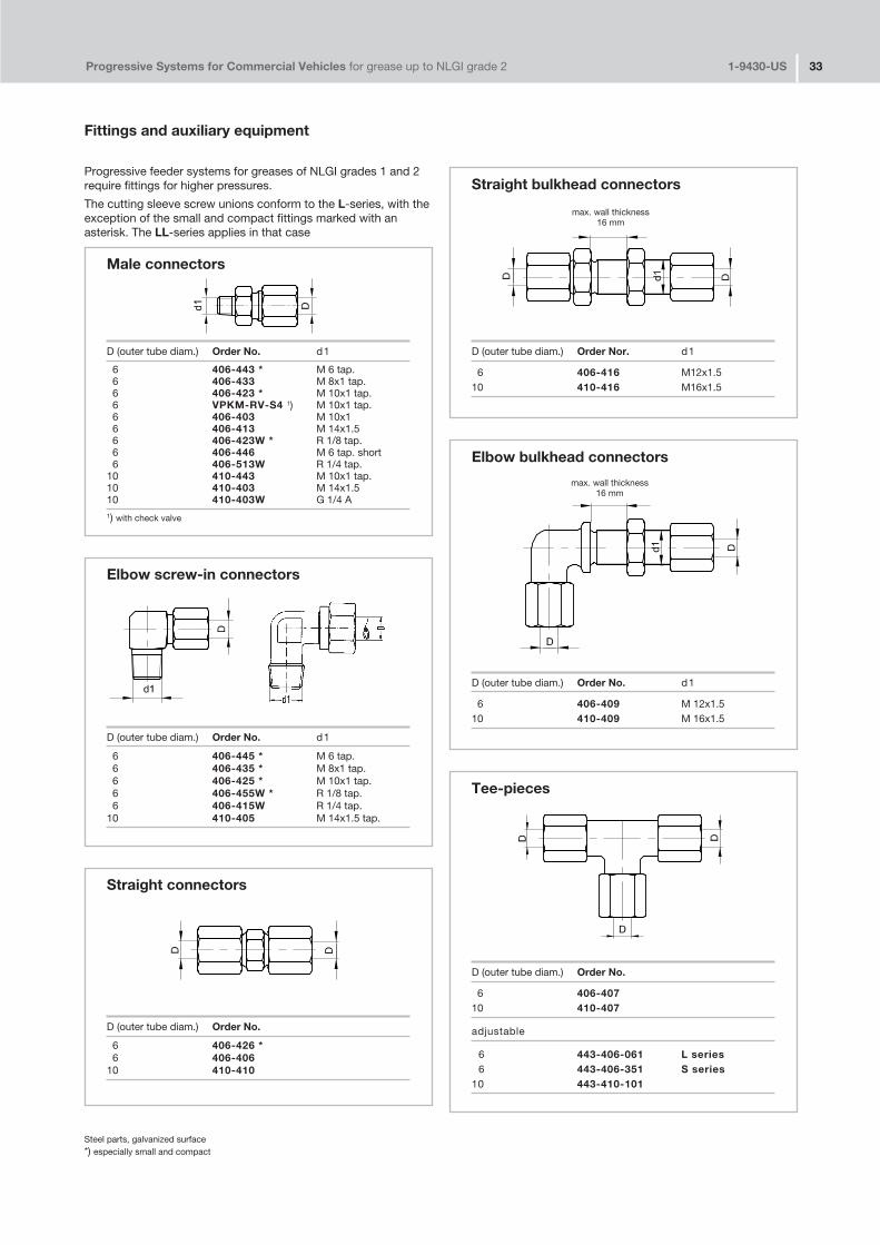
Fittings and auxiliary equipment
Male connectors
D (outer tube diam.) Order No. d1
6 406�443 * M 6 tap.6 406�433 M 8x1 tap.6 406�423 * M 10x1 tap.6 VPKM�RV�S4 1) M 10x1 tap.6 406�403 M 10x16 406�413 M 14x1.56 406�423W * R 1/8 tap.6 406�446 M 6 tap. short6 406�513W R 1/4 tap.
10 410�443 M 10x1 tap.10 410�403 M 14x1.510 410�403W G 1/4 A1) with check valve
Elbow screw�in connectors
D (outer tube diam.) Order No. d1
6 406�445 * M 6 tap.6 406�435 * M 8x1 tap.6 406�425 * M 10x1 tap.6 406�455W * R 1/8 tap.6 406�415W R 1/4 tap.
10 410�405 M 14x1.5 tap.
Straight connectors
D (outer tube diam.) Order No.
6 406�426 *6 406�406
10 410�410
Progressive feeder systems for greases of NLGI grades 1 and 2require fittings for higher pressures.
The cutting sleeve screw unions conform to the L�series, with theexception of the small and compact fittings marked with anasterisk. The LL�series applies in that case
Steel parts, galvanized surface*) especially small and compact
Straight bulkhead connectors
D (outer tube diam.) Order Nor. d1
6 406�416 M12x1.510 410�416 M16x1.5
Elbow bulkhead connectors
D (outer tube diam.) Order No. d1
6 406�409 M 12x1.510 410�409 M 16x1.5
Tee�pieces
D (outer tube diam.) Order No.
6 406�40710 410�407
adjustable
6 443�406�061 L series6 443�406�351 S series
10 443�410�101
max. wall thickness16 mm
max. wall thickness16 mm
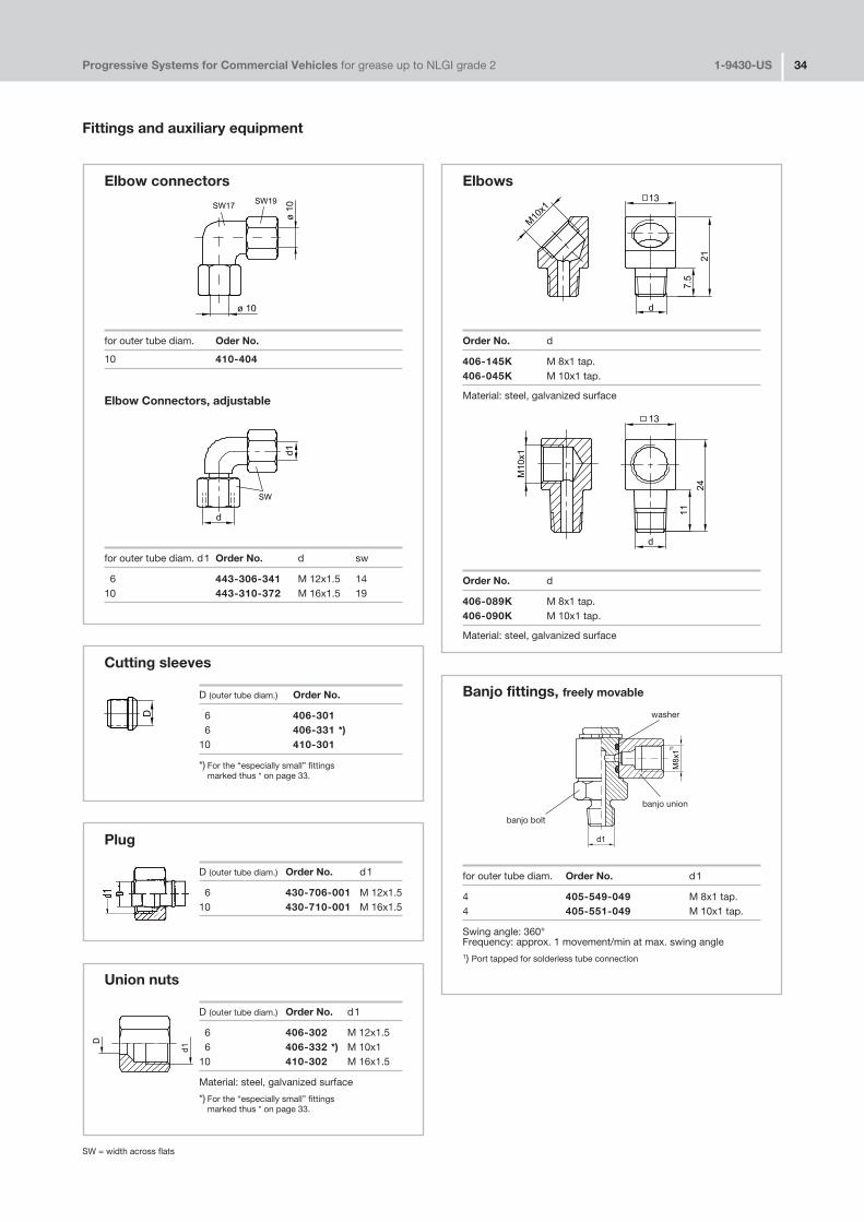
Progressive Systems for Commercial Vehicles for grease up to NLGI grade 2 1�9430�US 34
Fittings and auxiliary equipment
Elbow connectors
for outer tube diam. Oder No.
10 410�404
Elbow Connectors, adjustable
for outer tube diam. d1 Order No. d sw
6 443�306�341 M 12x1.5 1410 443�310�372 M 16x1.5 19
Elbows
Order No. d
406�145K M 8x1 tap.406�045K M 10x1 tap.
Material: steel, galvanized surface
Order No. d
406�089K M 8x1 tap.406�090K M 10x1 tap.
Material: steel, galvanized surface
Cutting sleeves
D (outer tube diam.) Order No.
6 406�3016 406�331 *)
10 410�301
*) For the “especially small” fittings marked thus * on page 33.
Plug
D (outer tube diam.) Order No. d1
6 430�706�001 M 12x1.510 430�710�001 M 16x1.5
Union nuts
D (outer tube diam.) Order No. d1
6 406�302 M 12x1.56 406�332 *) M 10x1
10 410�302 M 16x1.5
Material: steel, galvanized surface
*) For the “especially small” fittings marked thus * on page 33.
Banjo fittings, freely movable
for outer tube diam. Order No. d1
4 405�549�049 M 8x1 tap.4 405�551�049 M 10x1 tap.
Swing angle: 360°Frequency: approx. 1 movement/min at max. swing angle1) Port tapped for solderless tube connection
washer
banjo union
banjo bolt
SW = width across flats

Progressive Systems for Commercial Vehicles for grease up to NLGI grade 2 1�9430�US 35
Fittings and auxiliary equipment
Adapters with tapered thread for screwing into lubrication ports without sealing face
for outer tube diam. Order No. d1 d2 L1 L2 sw**)
4 404�662K M 6 tap. M 8x11) 19 5 114 404�663K M 6 tap. M 8x11) 20 6 114 404�673K M 6x0.75 tap. M 8x11) 20 6 114 404�047K M 7 tap. M 8x11) 20 6 114 404�003K M 8x1 tap. M 8x11) 17 7.4 114 404�045 M 8x1 tap. M 8x11) 62.5 7.4 114 404�006K M 10x1 tap. M 8x11) 16 7.4 114 401�004�512 M 10x1 tap. M 8x1 25 7.4 114 404�050 *) M 8x11) 18 5.2 114 853�460�000 *) M 8x11) 46 5.2 114 404�040K R 1/8 tap. M 8x11) 16 6 114 404�040K�US 1/8 NPTF M 8x1 20 6.7 114 404�054K R 1/4 tap. M 8x11) 14 9 144 404�072 1/4�28 UNF M 8x1 20 5.6 114 401�004�903 1/4 BSF M 8x1 20 5 114 401�004�904 3/16 BSF M 8x1 18 5 114.5 406�004K�S2 M 10x1 tap. M 10x1 18 7 134.5 456�004K�S2 R 1/8 tap. M 10x1 18 6 136 406�004K M 10x1 tap. M 10x11) 23 7.4 146 406�035K M 10x1 tap. M 10x1 40 8 14
Adapters with tapered threads areused without washers, sincetapered threads are self�sealing.Therefore, the ports do not have tobe provided with sealing faces.
Material:steel, galvanized surface
1) Ports tapped for solderless tubeconnection
2) Tapered thread according to DIN 158,tapered, short, or as per DIN 2999
*) Self�forming thread for 7.6 mm diam.borehole
**) sw = width across flats
Screw unions for steel and plastic tubing(use reinforcing socket for plastic tubing)
Reinforcing socket Taperedfor plastic tubing sleeves Socket unions
for outertube diam. Order No. Order No. Order No. d1
4 404�603 404�611 404�612�MS M 8x16x1.25 406�613 406�611 406�612�MS M 10x1
Material: brass
AssemblySlide socket union and tapered sleeve onto end of the tube.In the case of plastic tubing, first insert the reinforcingsocket. Insert end of tube into tapped port up to the stop.First tighten the socket union finger�tight and then turn itanother 11/2 turns.
Adapters with respective washers
for outer Adapter Washertube diam. Order No. d1 d2 l1 l2 sw**) Order No.
4 404�044 *) M 8x1 M 8x1 46 6 11 DIN7603�A8x11.5�CU4 404�004 M 8x1 M 8x1 24 14 11 DIN7603�A8x11.5�CU4 404�005 M 8x1 M 8x1 32 22 11 DIN7603�A8x11.5�CU4 404�006 M 10x1 M 8x1 18 7.5 14 504�0194 404�164 M 14x1.5 M 8x1 18 9 17 DIN7603�A14x18�CU 6 406�004 M 10x1 M 10x1 18 7.5 14 504�019 6 406�166 M 16x1.5 M 10x1 19 9 19 DIN7603�A16x20�CU6 406�054 G 1/4 A M 10x1 20 10 17 508�1088 408�004 M 10x1 M 14x1.5 28 7.5 17 504�0198 408�005 M 16x1.5 M 14x1.5 22 9 19 DIN7603�A16x20�CU8 301�020 G 1/4 A M 14x1.5 23 10 17 508�108
Material
Adapters:steel, galvanized surfaceWashers: copper
Please note!Order washers separately!
1) Ports tapped for solderless tubeconnection
*) extra long
**) sw = width across flats
tapped portreinforcing socket(for plastic tubing)
tapered sleeve
socket union
1)
1)
2)
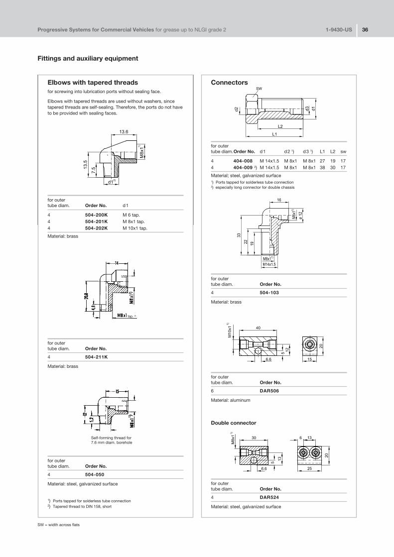
Fittings and auxiliary equipment
Progressive Systems for Commercial Vehicles for grease up to NLGI grade 2 1�9430�US 36
Connectors
for outertube diam.Order No. d1 d2 1) d3 1) L1 L2 sw
4 404�008 M 14x1.5 M 8x1 M 8x1 27 19 174 404�009 2) M 14x1.5 M 8x1 M 8x1 38 30 17
Material; steel, galvanized surface1) Ports tapped for solderless tube connection2) especially long connector for double chassis
for outertube diam. Order No.
4 504�103
Material: brass
for outertube diam. Order No.
6 DAR506
Material: aluminum
Double connector
for outertube diam. Order No.
4 DAR524
Material: steel, galvanized surface
Elbows with tapered threadsfor screwing into lubrication ports without sealing face.
Elbows with tapered threads are used without washers, sincetapered threads are self�sealing. Therefore, the ports do not haveto be provided with sealing faces.
for outertube diam. Order No. d1
4 504�200K M 6 tap.4 504�201K M 8x1 tap.4 504�202K M 10x1 tap.
Material: brass
for outer tube diam. Order No.
4 504�211K
Material: brass
for outertube diam. Order No.
4 504�050
Material: steel, galvanized surface
1) Ports tapped for solderless tube connection2) Tapered thread to DIN 158, short
Self�forming thread for7.6 mm diam. borehole
tap. 2)
SW = width across flats
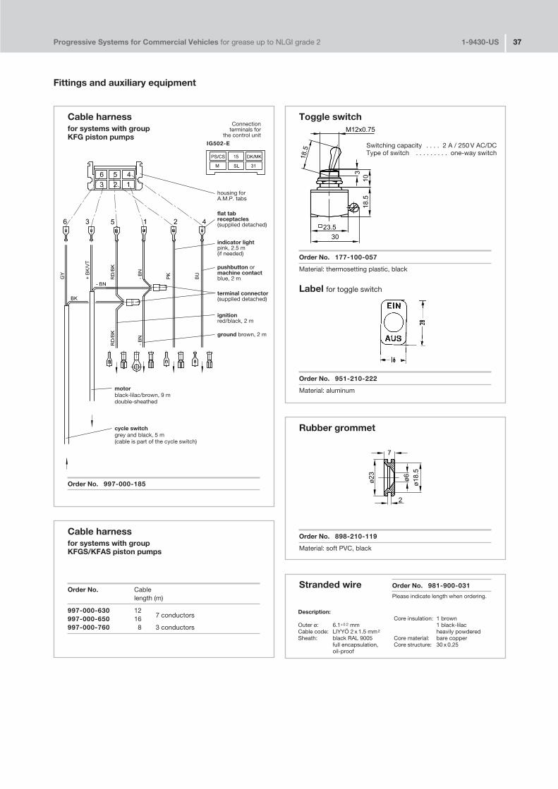
Progressive Systems for Commercial Vehicles for grease up to NLGI grade 2 1�9430�US 37
Fittings and auxiliary equipment
Cable harnessfor systems with groupKFG piston pumps
Order No. 997�000�185
Stranded wire Order No. 981�900�031
Please indicate length when ordering.
Description:Core insulation: 1 brown
Outer ø: 6.1+0.2 mm 1 black�lilacCable code: LIYYÖ 2 x 1.5 mm2 heavily powderedSheath: black RAL 9005 Core material: bare copper
full encapsulation, Core structure: 30 x 0.25oil�proof
housing for A.M.P. tabs
flat tabreceptacles(supplied detached)
indicator lightpink, 2.5 m(if needed)
pushbutton ormachine contactblue, 2 m
terminal connector(supplied detached)
ignitionred/black, 2 m
ground brown, 2 m
Connectionterminals for
the control unit
IG502�E
motor black�lilac/brown, 9 mdouble�sheathed
cycle switchgrey and black, 5 m(cable is part of the cycle switch)
Toggle switch
Order No. 177�100�057
Material: thermosetting plastic, black
Label for toggle switch
Order No. 951�210�222
Material: aluminum
Switching capacity . . . . 2 A / 250 V AC/DCType of switch . . . . . . . . . one�way switch
Rubber grommet
Order No. 898�210�119
Material: soft PVC, black
Cable harnessfor systems with groupKFGS/KFAS piston pumps
Order No. Cablelength (m)
997�000�630 127 conductors997�000�650 16
997�000�760 8 3 conductors

Progressive Systems for Commercial Vehicles for grease up to NLGI grade 2 1�9430�US 38
Fittings and auxiliary equipment
Illuminated pushbuttonround
Order No. Pushbutton Voltage Power
177�100�062 greenmax. 24 V 2 W
177�100�065 yellow
Filament lamp (please order separately)
179�100�043 12 or 24 V 2 W
Please indicate 12 V or 24 V voltage when ordering.
corneredInstallation opening
Order No. Voltage
177�100�063 24 V177�100�064 12 V
Control lightfor illuminated pushbutton, cornered
Order No. Pushbutton Voltage
179�100�078+924 green 24 V179�100�088+912 yellow 12 V
Symbol insertCentral lubrication
for illuminated pushbutton 177�100�063 / �064 andcontrol light 179�100�078 /�088
Order No. Pushbutton Voltage
951�110�991 yellow 24 V951�110�992 green 12 V
Circular connector, 4�pole typefor cycle switches
without cable
Order No. Version
179�990�371 straight179�990�372 angled
with 4�core cable, 5 m long
Order No. Version
179�990�600 straight179�990�601 angled
Indicator light fitted with filament lamp
Order No. Face Voltage Power
P�66.60GRUEN greenP�66.60ROT red 12 or 24 V 2 WP�66.60GELB yellow
Spare filament lamp
P�66.62 12 or 24 V 2 W
Please indicate 12 V or 24 V voltage when ordering.
Nameplate
Order No.
760�048 (for indicator light P�66.60)951�120�025 (for illuminated pushbutton 177�100�062/�065)
Material: PVC and thermoplastic, acid� and base�resistant, 0.5 mm thick
P
N
3
4
▼
Tab connector2.8 x 0.8 mm
Installed diam.20.3 mm
M12x1
"L"
42
15
M12x1
27
31"L"
45°
15
M12x1
19.5
54
Max. operating voltage . . . . . . . . . . 0 to 30 V AC/DCMax. operating current . . . . . . . . . . 3 ATemperature range . . . . . . . . . . . . . . – 40 to + 85 °C
Max. operating voltage . . . . . . . . . . 10 to 30 V AC/DCMax. operating current . . . . . . . . . . 4 ATemperature range . . . . . . . . . . . . . . – 25 to + 90 °C
M12x1
36
29
19.5
P
N
3
4
▼
P
N
Tab 6.3x0.8

Progressive Systems for Commercial Vehicles for grease up to NLGI grade 2 1�9430�US 39
Fittings and auxiliary equipment
Fixing bolts
Hexagonal head bolts
Order No. l b k sw e
DIN933�M6x20�8.8 20 20 4 10 11.1DIN933�M6x25�8.8 25 25 4 10 11.1DIN931�M6x30�8.8 30 18 4 10 11.1DIN933�M6x35�8.8 35 35 4 10 11.1DIN931�M6x40�8.8 40 18 4 10 11.1DIN933�M6x45�8.8 45 45 4 10 11.1DIN931�M6x55�8.8 55 18 4 10 11.1DIN933�M8x25�8.8 25 25 5.5 13 14.4DIN933�M8x35�8.8 35 35 5.5 13 14.4
Material: steel, galvanized surface
Self�tapping screws
Order No. l d1 d2
DIN7981�B4.2x9.5 9.5 4.2 8.2DIN7981�BZ4.8x9.5 9.5 4.8 9.5DIN7981�BZ4.8x13 13 4.8 9.5
Material: steel, galvanized surface
Lock washers
Order No. for bolt d1 d2 s h
650�060 M 6 6.4 10 0.7 0.9650�080 M 8 8.4 13 0.8 1.2650�140 M 14 15 22 1.2 1.8650�160 M 16 17 24 1.3 1.9650�200 M 20 21 30 1.5 2.2
Material: spring steel
Body washers
Order No. d1 d2 s
821�400�006 6.6 28 2821�400�010 8.4 30 1.5
Material: steel, galvanized surface
Screw plugsand respective flat washers
Screw plugs Flat washersOrder No. d1 Order No.
404�011 M 8x1 DIN7603�A8x11.5�CU406�011 M 10x1.5 504�019408�011 M 14x1.5 DIN7603�A14x18�CU
Material: steel, galvanized surface Material: copper
Please note!Order flat washersseparately!
Nuts
Order No. d1 m sw e
DIN934�M6�8 M 6 5 10 11.5DIN934�M8�8 M 8 6.5 13 14.4DIN936�M14x1.5�5 M 14x1.5 8 22 25.4DIN936�M16x1.5�5 M 16x1.5 8 24 27.7DIN936�M20x1.5�5 M 20x1.5 9 30 34.6
Material: steel, galvanized surface
SW = width across flats

Fittings and auxiliary equipment
Progressive Systems for Commercial Vehicles for grease up to NLGI grade 2 1�9430�US 40
TubingSteel tubing, galvanized
minimum bending radius rbent with bent with
Order No. d a s d i mandrel grooved disk
WV�RO4x0.7VERZI 4 0.7 2.6 6 –WV�RO6 x0.7VERZI 6 0.7 4.6 22 16WV�RO6x1VERZI 6 1.0 4.0 22 16WV�RO10x1VERZI 10 1.0 8.0 71 27
Diesel injection pipeDIN73000A2�6ST30AL 6 2.0 2.0 22 16
Plastic tubing, WVN715, unplasticized/semi�rigid as per DIN 73378
Order No. Code d a s d i minimum bending radius r
WVN715�RO4x0.85+A89 4 0.85 2.3 38WVN715�RO6x1.25+A89 6 1.25 3.5 63WVN715�RO6x1.5 +A89 6 1.5 3.0 63
color: black
The plastic tubing can also be supplied filled with NLGI grade 2, code AF 5.The respective code and tubing length must be added to the order No.
Order example:Plastic tubing WVN715�RO4x0.85, black color, 5 m long:
Order No. WVN715�RO4x0.85+A89x5mPlastic tubing WVN715�RO4x0.85, black color, filled with grease, 8 m long:
Order No. WVN715�RO4x0.85+AF5x8m
Hoses
For secondary lines(connection: feeder � lubrication point)
ExternalL + 5 Order No. tube diam. Hose diam. d 3
220 734�220�K260 734�260�K300 734�300�K
4 8.8 M 8 x1
340 734�340�K
Complete with socket unions and double tapered sleeves
Material hose oil�proof internal and external rubber with braided layer of rayon.tube ends: steel tubing, ends permanently joined to the hose.
Please note! These hoses must not be used as main lines.
Corrugated hoseOrder No. rated width da x s d i L
982�760�070 4 7x1.25 4982�760�120 8 11.7x1.6 8.4982�760�130 10 12.9x1.5 10 982�760�160 12 15.7x1.7 12.3
up to max. of 50 m *)
Material: polyamide 6, black color *) please indicate when ordering
Sleevesfor corrugated hose 982�760�130(rated width 10)
Order No.2�hole:898�210�047
3�hole:898�210�075
4�hole:898�210�063
Please note!see screw unionswith reinforcing socketsfor plastic tubing.
double tapered sleeve
socket union

Progressive Systems for Commercial Vehicles for grease up to NLGI grade 2 1�9430�US 41
Fittings and auxiliary equipment
Hoses for self�installation
for main lines (connection: pump – feeder)
and secondary lines (connection: feeder – lubrication point)
*) Take length of engaged thread into account twice when determining the length of the hose.
Designation Order No. L (mm) a (mm) b (mm)
➀ High�pressure hose, max. length supplied 50 m 982�750�091High�pressure hose, max. length supplied 50 m 982�750�091+AF2filled with NLGI grade 2 greaseHigh�pressure hose, max. length supplied 50 m 982�750�092+AF2steel�sheathed (associated clip, order No. 941�514�101)
➁ Sleeve 853�540�010
➂ Tube stub, straight 853�370�002 20853�380�002 30853�390�002 66
with claw groove for plug�in connector 853�370�002�VS 20853�380�002�VS 30
� Tube stub, 90° angle 853�380�003 2 21853�390�003 13 47853�390�004 13 36
with claw groove for plug�in connector 853�380�003�VS 2 21
Technical data Materials:
Hose: hose : inner lining .............. unplasticized polyesterrupture pressure .............. 800 bars inner layer ............... braided synthetic fibersmin. bending radius ........ 35 mm outer cover ............. weatherproof polyurethane
sleeve, tube stub: .............. steel, galvanized
for main lines (connection: pump – feeder)
*) Take length of engaged thread into account twice when determining the length of the hose.
Designation Order No.
➀ High�pressure (max. length supplied 100 m) WVN711�10High�pressure (max. length supplied. 50 m) WVN711�10+AF2filled with NLGI grade 2 grease
➁ Sleeve 406�810�002
➂ Tube stub 406�710�002
Technical data Materials:
Hose: hose : inner lining .............. Perbunanrupture pressure .............. 315 bars inner layer ............... diagonally woven synthetic fibersmin. bending radius ........ 55 mm outer cover ............. weatherproof neoprene
sleeve: ............................... aluminum alloytube stub: .......................... steel, galvanized

Progressive Systems for Commercial Vehicles for grease up to NLGI grade 2 1�9430�US 42
Fittings and auxiliary equipment
Spacer ring
Order No. 898�210�061
Material: CR (chloroprene rubber)
Clips
for outer tube diam. D Order No. L number of tubes
4 604�001�A 9 14 604�002�A 9 26 606�010�A 10 18 608�001�A 12 1
Material: mild steel, galvanized surface
for outer tube diam. D Order No. d b L
4 941�204�104 5.2 15 106 941�206�104 5.2 15 116 941�206�108 6.4 18.5 14.28 941�208�104 6.4 18.5 15.29 941�209�104 5.2 15 12.59 941�209�105 6.4 18.5 15.7
10 941�210�104 6.4 18.5 16.212 941�212�104 6.4 18.5 17.213 941�213�104 6.4 18.5 17.715 941�215�104 6.4 18.5 18.717 941�217�104 5.2 15 16.517 941�217�105 6.4 18.5 19.718 941�218�101 6.4 18.5 20.120 941�220�104 6.4 18.5 21.222 941�222�100 6.4 18.5 22.225 941�225�104 6.4 18.5 23.727 941�227�104 10.2 31 31
for outer tube diam. D Order No. l l 1
9 941�309�204 12.5 917 941�317�204 16.5 17
Cable strap
Order No. l b
898�610�000 197 4.9898�710�000 302 4.9898�710�001 360 7.5
Material: polyamide
For automatic pincers:
Order No. 898�510�002
Material: polyamide
Mounting base
Order No. 179�990�186
lubricationlines
brakehose
spacer ringcablestrap
corrugatedtube
rubber profile
rubber profileself�stickfoil
separating cut
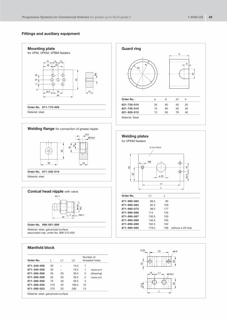
Progressive Systems for Commercial Vehicles for grease up to NLGI grade 2 1�9430�US 43
Fittings and auxiliary equipment
Mounting plate for VPM, VPKM, VPBM feeders
Order No. 871�770�006
Material: steel
Guard ring
Order No. a d d1 h
821�730�010 20 60 50 20821�750�010 10 60 50 40821�950�010 13 90 78 40
Material. Steel
Manifold block
Number ofOrder No. L L1 L2 threaded holes
871�340�006 30 – 19.5 1871�340�008 30 – 19.5 1 nipple port
871�360�006 50 20 39.5 2 (drawing)871�360�008 50 20 39.5 2 nipple port
871�380�006 70 40 59.5 3871�390�020 210 20 199.5 10871�390�023 270 20 200 13
Material: steel, galvanized surface
Welding flange for connection of grease nipple
Order No. 871�530�010
Material: steel
Welding platesfor VPKM feeders
Order No. L1 L
871�990�083 66.5 85871�990�084 82.5 100871�990�073 98.5 177871�990�086 114 135871�990�087 130.5 150871�990�088 146.5 165871�990�089 162.5 182871�990�065 178.5 199 without ø 20 hole
Conical head nipple with valve
Order No. 996�001�890
Material: steel, galvanized surfaceassociated cap, order No. 898�210�050
8 mm thick
tap
.

Progressive Systems for Commercial Vehicles for grease up to NLGI grade 2 1�9430�US 44
Fittings and auxiliary equipment
Pump fastening platefor systems with group KFG/KFGS piston pumps
Order No.
KFG1.U16 without square tubeKFG1.U17 (drawing)
Order No. 881�290�430
square tube
Drilling template for piston pumps
type KFG
Order No. 951�130�115
Material: self�stick paper
type KFA
Order No. 951�130�148
Material self�stick paper
Drilling templatefor progressive feeder, type VPBM
Order No. 951�130�145
Material: self�stick paper
3 holes imprintedonly
3 holes imprintedonly
2 holes with 7 mmdiam. imprinted only
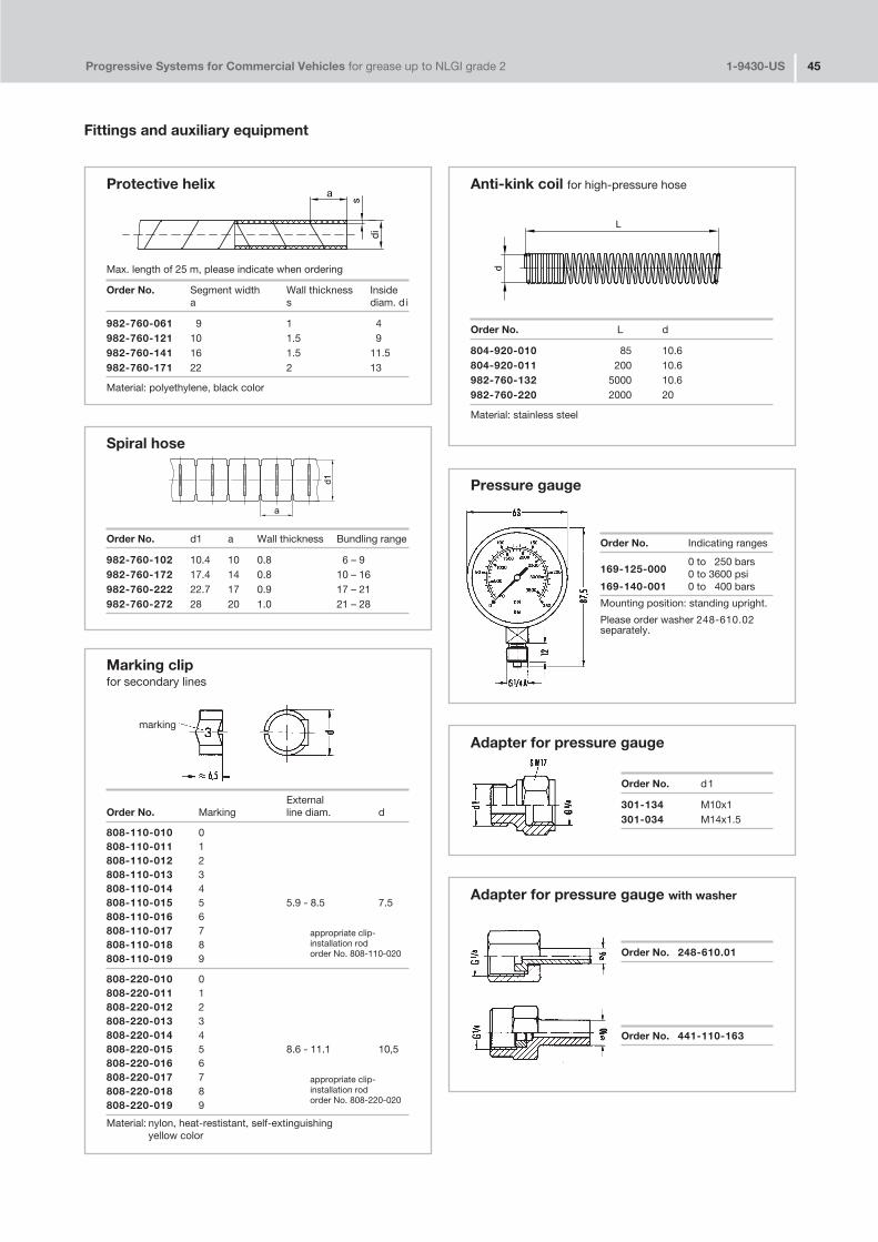
Progressive Systems for Commercial Vehicles for grease up to NLGI grade 2 1�9430�US 45
Fittings and auxiliary equipment
Protective helix
Max. length of 25 m, please indicate when ordering
Order No. Segment width Wall thickness Insidea s diam. d i
982�760�061 9 1 4982�760�121 10 1.5 9982�760�141 16 1.5 11.5982�760�171 22 2 13
Material: polyethylene, black color
Marking clipfor secondary lines
ExternalOrder No. Marking line diam. d
808�110�010 0808�110�011 1808�110�012 2808�110�013 3808�110�014 4808�110�015 5 5.9 � 8.5 7.5808�110�016 6808�110�017 7808�110�018 8808�110�019 9
808�220�010 0808�220�011 1808�220�012 2808�220�013 3808�220�014 4808�220�015 5 8.6 � 11.1 10,5808�220�016 6808�220�017 7808�220�018 8808�220�019 9
Material: nylon, heat�restistant, self�extinguishingyellow color
Anti�kink coil for high�pressure hose
Order No. L d
804�920�010 85 10.6804�920�011 200 10.6982�760�132 5000 10.6982�760�220 2000 20
Material: stainless steel
marking
appropriate clip�installation rodorder No. 808�110�020
appropriate clip�installation rodorder No. 808�220�020
Spiral hose
Order No. d1 a Wall thickness Bundling range
982�760�102 10.4 10 0.8 6 – 9982�760�172 17.4 14 0.8 10 – 16982�760�222 22.7 17 0.9 17 – 21982�760�272 28 20 1.0 21 – 28
Pressure gauge
Order No. Indicating ranges
169�125�0000 to 250 bars0 to 3600 psi
169�140�001 0 to 400 bars
Mounting position: standing upright.
Please order washer 248�610.02separately.
Adapter for pressure gauge
Order No. d1
301�134 M10x1301�034 M14x1.5
Adapter for pressure gauge with washer
Order No. 248�610.01
Order No. 441�110�163
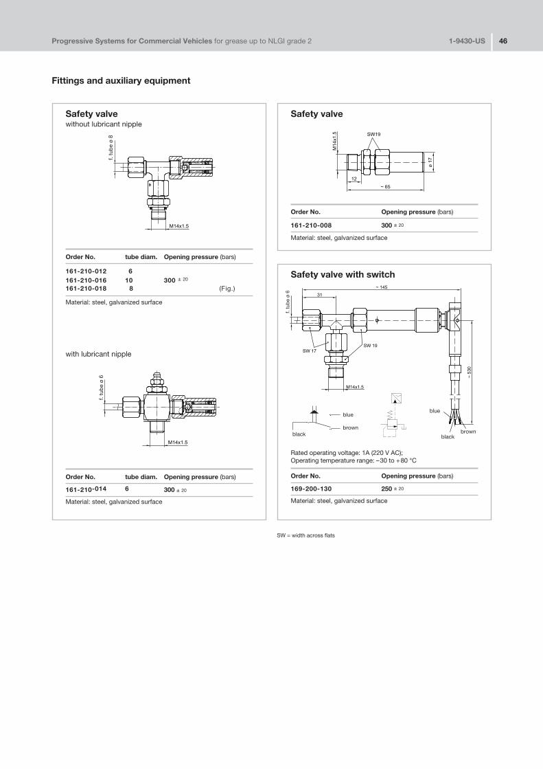
Progressive Systems for Commercial Vehicles for grease up to NLGI grade 2 1�9430�US 46
Fittings and auxiliary equipment
Safety valve
Order No. Opening pressure (bars)
161�210�008 300 ± 20
Material: steel, galvanized surface
Safety valvewithout lubricant nipple
Order No. tube diam. Opening pressure (bars)
161�210�012 6161�210�016 10 300 ± 20
161�210�018 8 (Fig.)
Material: steel, galvanized surface
with lubricant nipple
Order No. tube diam. Opening pressure (bars)
161�210�014 6 300 ± 20
Material: steel, galvanized surface
Safety valve with switch
Rated operating voltage: 1A (220 V AC);Operating temperature range: –30 to +80 °C
Order No. Opening pressure (bars)
169�200�130 250 ± 20
Material: steel, galvanized surface
blueblue
brownbrownblack black
f. tu
be
ø 8
f. tu
be
ø 6
f. tu
be
ø 6
SW = width across flats
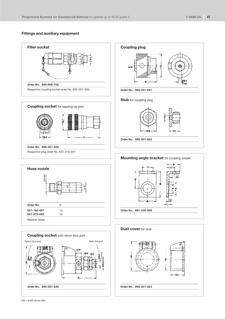
Progressive Systems for Commercial Vehicles for grease up to NLGI grade 2 1�9430�US 47
Fittings and auxiliary equipment
Filler socket
Order No. 995�000�705
Respective coupling socket order No. 995�001�500
Coupling plug
Order No. 995�001�621
Stub for coupling plug
Order No. 995�001�622
Mounting angle bracket for coupling socket
Order No. 881�430�000
Coupling socket for topping�up port
Order No. 995�001�500
Respective plug order No. 833�370�001
Hose nozzle
Order No. d
857�760�007 13857�870�002 16
Material: brass
Coupling socket with return flow port
Order No. 995�001�620
Dust cover for stub
Order No. 995�001�623
Return flow port Main line port
10 d
eep
SW = width across flats
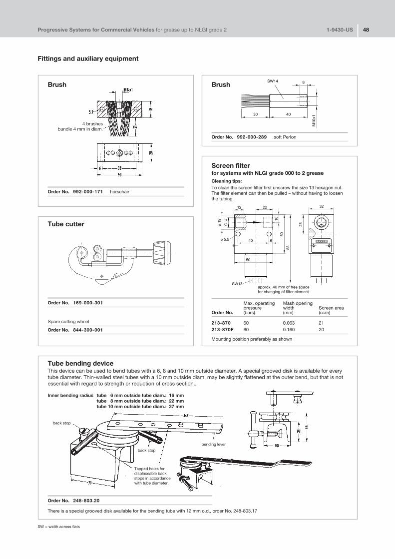
Tube bending deviceThis device can be used to bend tubes with a 6, 8 and 10 mm outside diameter. A special grooved disk is available for everytube diameter. Thin�walled steel tubes with a 10 mm outside diam. may be slightly flattened at the outer bend, but that is notessential with regard to strength or reduction of cross section..
Inner bending radius tube 6 mm outside tube diam.: 16 mmtube 8 mm outside tube diam.: 22 mmtube 10 mm outside tube diam.: 27 mm
Order No. 248�803.20
There is a special grooved disk available for the bending tube with 12 mm o.d., order No. 248�803.17
Progressive Systems for Commercial Vehicles for grease up to NLGI grade 2 1�9430�US 48
Fittings and auxiliary equipment
Brush
Order No. 992�000�171 horsehair
Brush
Order No. 992�000�289 soft Perlon
4 brushes bundle 4 mm in diam.
Screen filterfor systems with NLGI grade 000 to 2 greaseCleaning tips:To clean the screen filter first unscrew the size 13 hexagon nut.The filter element can then be pulled – without having to loosenthe tubing.
Max. operating Mash openingpressure width Screen area
Order No. (bars) (mm) (ccm)
213�870 60 0.063 21213�870F 60 0.160 20
Mounting position preferably as shown
approx. 40 mm of free space for changing of filter element
Tube cutter
Order No. 169�000�301
Spare cutting wheel
Order No. 844�300�001
back stop
bending lever
Tapped holes fordisplaceable backstops in accordancewith tube diameter.
back stop
SW = width across flats
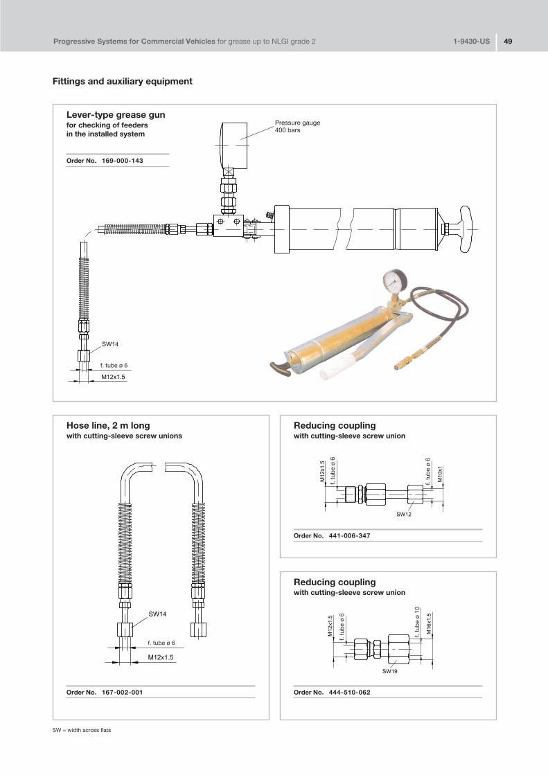
Progressive Systems for Commercial Vehicles for grease up to NLGI grade 2 1�9430�US 49
Fittings and auxiliary equipment
Reducing couplingwith cutting�sleeve screw union
Order No. 444�510�062
Lever�type grease gunfor checking of feedersin the installed system
Order No. 169�000�143
Hose line, 2 m longwith cutting�sleeve screw unions
Order No. 167�002�001
Reducing couplingwith cutting�sleeve screw union
Order No. 441�006�347
Pressure gauge400 bars
f. tube ø 6
f. tube ø 6
f. tu
be
ø 6
f. tu
be
ø 6
f. tu
be
ø 6
f. tu
be
ø 10
SW = width across flats

Progressive Systems for Commercial Vehicles for grease up to NLGI grade 2 1�9430�US 50
Notes


Willy Vogel AGMotzener Strasse 35/3712277 Berlin, GermanyP.O. Box 97 04 44 · 12704 Berlin
Phone (++49) 30�7 20 02�0Fax (++49) 30�7 20 02�111E�mail info@vogel�berlin.deInternet www.vogelag.com
Sub
ject
to
chan
ge w
ithou
t no
tice!
V
000
09/2
002


