Verification of behavioral models of Analog & Mixed Signal IP (Phase Locked Loop) Sahil Narang (13MECV31) Internal Guide Prof. Akash Mecwan Nirma University External Guide Hardik Parekh Analog Design Engineer ST Microelectronics Pvt. Ltd.
Transcript
Verification of behavioral models
of Analog & Mixed Signal IP
(Phase Locked Loop)
Sahil Narang (13MECV31)
Internal Guide
Prof. Akash Mecwan
Nirma University
External Guide
Hardik Parekh
Analog Design Engineer
ST Microelectronics Pvt. Ltd.
Agenda……
• Motivation
• Introduction to Phase Locked Loop
• Modes of PLL
• Requirement for Automated Generic Test Bench
• Flow diagram for Generic Test Bench
• Current progress
• Future Work
• Conclusion
• References
2
Motivation 3
• There are different types of Phase Locked Loop (PLL) but most
of the functionality is same.
• Making an automated test bench for all different type of PLL
can be made which will run all the test cases for specific
functionality of PLL with minimum number of input
required.
• It reduces the huge time in verification.
Introduction to Phase Locked Loop
A phase-locked loop is a feedback system combining a voltage
controlled oscillator (VCO) and a phase comparator so connected
that the oscillator maintains a constant phase angle relative to a
reference signal.
4
Figure 1: Design Phase Locked Loop
Modes of PLL
• Integer Mode PLL
• Fractional Mode PLL
• Spread Spectrum Clock Generation PLL
• Clock Insertion Mode PLL
• Free Running PLL
• Bypass Mode PLL
5
Modes of PLL continued… 6
Figure 2: SSCG And Fractional Mode PLL
Modes of PLL continued… 7
Figure 3 : Free Running and Clock Insertion Mode PLL
Requirement for Automated Generic Test
Bench
• Configuration file which includes minimum inputs
required from user.
• Generation of internal configuration file which includes all
the parameters required for verification.
• All the possible test cases for verification.
• Generation of an automated script which will run all the
test cases automatically and gives a report.
8
Flow diagram for Generic Test Bench 9
Figure 4: Verification Environment for Behavioral Models of Phase Locked Loop
Compiler Configuration File/ User Input
Configuration File
• This file is used for extracting pin list with sizes.
• This file can be configured in two forms..
o Compiler configuration file or
o User Input configuration file
• This file will require minimum number of inputs from user.
• It provides the information about the test modes i.e. which
test cases have to run and the parameters required for
verification with the help of script.
10
Generation of Configuration File for Generic
Test Bench• This configuration file will extract the data from user
configuration file.
• It includes all the parameters which supports all the modes of
PLL.
o Minimum & maximum input frequency
o Minimum & maximum output frequency
o Maximum allowable jitter at input clock
o Maximum delay in lock
o Minimum width of power down pulse
11
Generic Driver & Checker
• In this file all the test cases will be written which have
to run on DUT.
• It will also support user defined test cases which are
not supported by the test bench.
12
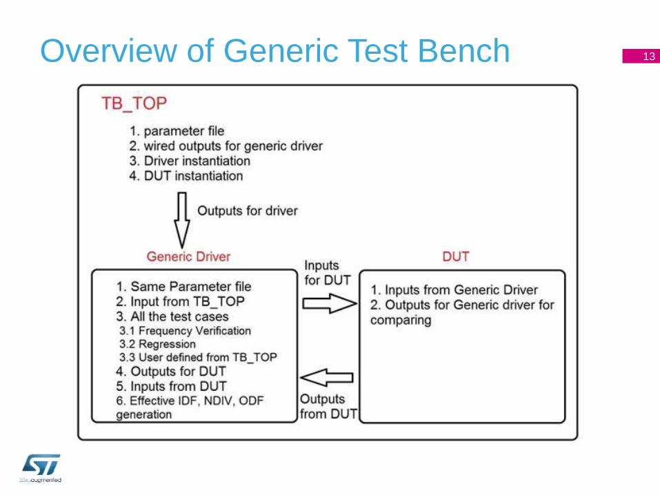
Overview of Generic Test Bench 13
Figure 5: When Power Supply is X or Z or Logic Low, all outputs should be corrupted
Figure 6: When ENABLE = X, All output should be corrupted
Figure 7: When INFF = X all the outputs should be X
Figure 8: When Input Divider Bits = X, all output should be corrupted
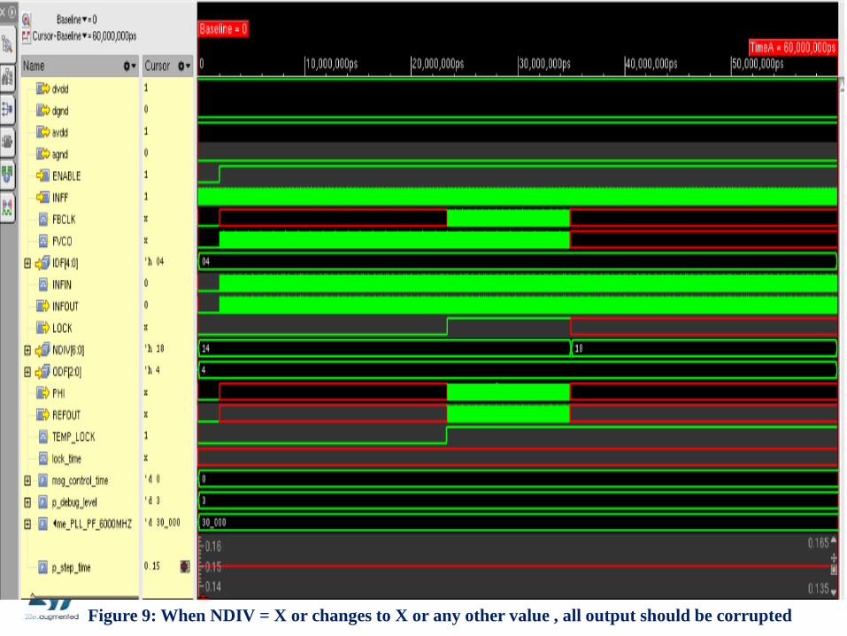
Figure 9: When NDIV = X or changes to X or any other value , all output should be corrupted
Figure 10: When ODF = X, Only PHI should be X
Regression Script
• This script will be used for running all possible test
cases for all supported modes.
• It will generate a report based on tests which will also
compared with the specifications.
20
Current progress
• Phase 1
• Generation of Test plan – Completed
• Development of flow diagram / algorithm – Completed
• Development of test bench configuration file for required
user inputs + Internal usage – Completed
• Generation of Generic test bench – On-going
• Top level script to run all possible test cases based on
configuration – Need to be done
21
Future Work
• Phase 2
• Static Checker Implementation
• Functional Coverage
22
Conclusion
• Verification of analog IP is very time taking such that it will
create a large time to market. Use of behavioural models of
analog IP is very time consuming. Accuracy degrades as
compare to analog simulations.
• A number of test cases are applied to PLL DUT with the help
of script reduces very much amount for testing PLL.
• Analog testing of PLL for all test cases takes almost an year
but with the help of this verification environment, verification


![[INSERT PROJECT NAME]€¦ · Project name Project Number [Where applicable] Project Manager Project Controller Project location [Insert brief details of project location, including](https://static.documents.pub/doc/80x56/603496f741d854077e52cec0/insert-project-name-project-name-project-number-where-applicable-project-manager.jpg)


