EL EC TR IF Y T HE W OR L D FM =I2I B W RV IP BWR Vessel & Internals Project 2003-154 May 23, 2003 Document Control Desk U. S. Nuclear Regulatory Commission 11555 Rockville Pike Rockville, MD 20852 Attention: Ms. Meena Khanna Subject: Project 704 - Non Proprietary Version of "BWRVIP-97: BWR Vessel and Internals Project, Guidelines for Performing Weld Repairs to Irradiated BWR Internals", EPRI Report 1003020NP Reference: Letter from Carl Terry (BWRVIP Chairman) to C.E. Carpenter (NRC) "Project 704-- BWRVIP-97: BWR Vessel and Internals Project, Guidelines for Performing Weld Repairs to Irradiated BWR Internals", dated November 27, 2001 Enclosed are ten (10) copies of the non proprietary BWRVIP report "BWRVIP-97NP: BWR Vessel and Internals Project, Guidelines for Performing Weld Repairs to Irradiated BWR Internals". The proprietary version of this report was submitted to the NRC by the BWRVIP letter referenced above. Should you have any questions regarding the subject report, please contact Denver Atwood, BWRVIP Repair Focus Group Chairman, at 205.992.7461. Sincerely, Carl Terry Constellation Generation Group Nine Mile Point Nuclear Station Chairman, BWR Vessel and Internals Project CORPORATE HEADOUARTERS 3412 Hiliview Avenue I Palo Alto CA 94304-1395 USA I 650.B55.2000 I Customer Service 800.313.3774 www.epri.com >ODg)59
Transcript
EL EC TR IF Y T HE W OR L D FM =I2I
B W RV I P BWR Vessel & Internals Project 2003-154
May 23, 2003
Document Control DeskU. S. Nuclear Regulatory Commission11555 Rockville PikeRockville, MD 20852
Attention: Ms. Meena Khanna
Subject: Project 704 - Non Proprietary Version of "BWRVIP-97: BWR Vessel and InternalsProject, Guidelines for Performing Weld Repairs to Irradiated BWR Internals",EPRI Report 1003020NP
Reference: Letter from Carl Terry (BWRVIP Chairman) to C.E. Carpenter (NRC) "Project704-- BWRVIP-97: BWR Vessel and Internals Project, Guidelines for PerformingWeld Repairs to Irradiated BWR Internals", dated November 27, 2001
Enclosed are ten (10) copies of the non proprietary BWRVIP report "BWRVIP-97NP: BWRVessel and Internals Project, Guidelines for Performing Weld Repairs to Irradiated BWRInternals". The proprietary version of this report was submitted to the NRC by the BWRVIPletter referenced above.
Should you have any questions regarding the subject report, please contact Denver Atwood,BWRVIP Repair Focus Group Chairman, at 205.992.7461.
Sincerely,
Carl TerryConstellation Generation GroupNine Mile Point Nuclear StationChairman, BWR Vessel and Internals Project
CORPORATE HEADOUARTERS
3412 Hiliview Avenue I Palo Alto CA 94304-1395 USA I 650.B55.2000 I Customer Service 800.313.3774 www.epri.com
>ODg)59
BWRVIP-97NP: BWR Vessel and Internals ProjectGuidelines for Performing Weld Repairs toIrradiated BWXR Internals
Technical Report
NON-PROPRIETARY INFORMATIONNOTICE: This report contains the non-proprietary information that is included in
the proprietary version of this report. The proprietary version of thisreport contains proprietary information that is the intellectual propertyof BWRVIP utility members and EPRI. Accordingly, the proprietaryreport is available only under license from EPRI and may not bereproduced or disclosed, wholly or in part, by any Licensee to anyother person or organization.
DISCLAIMER OF WARRANTIES AND LIMITATION OF LIABILITIES
THIS DOCUMENT WAS PREPARED BY THE ORGANIZATION(S) NAMED BELOW AS ANACCOUNT OF WORK SPONSORED OR COSPONSORED BY THE ELECTRIC POWER RESEARCHINSTITUTE, INC. (EPRI). NEITHER EPRI, ANY MEMBER OF EPRI, ANY COSPONSOR, THEORGANIZATION(S) BELOW, NOR ANY PERSON ACTING ON BEHALF OF ANY OF THEM:
(A) MAKES ANY WARRANTY OR REPRESENTATION WHATSOEVER, EXPRESS OR IMPLIED, ()WITH RESPECT TO THE USE OF ANY INFORMATION, APPARATUS, METHOD, PROCESS, ORSIMILAR ITEM DISCLOSED IN THIS DOCUMENT, INCLUDING MERCHANTABILITY AND FITNESSFOR A PARTICULAR PURPOSE, OR (II) THAT SUCH USE DOES NOT INFRINGE ON ORINTERFERE WITH PRIVATELY OWNED RIGHTS, INCLUDING ANY PARTY'S INTELLECTUALPROPERTY, OR (Ill) THAT THIS DOCUMENT IS SUITABLE TO ANY PARTICULAR USER'SCIRCUMSTANCE; OR
(B) ASSUMES RESPONSIBILITY FOR ANY DAMAGES OR OTHER LIABILITY WHATSOEVER(INCLUDING ANY CONSEQUENTIAL DAMAGES, EVEN IF EPRI OR ANY EPRI REPRESENTATIVEHAS BEEN ADVISED OF THE POSSIBILITY OF SUCH DAMAGES) RESULTING FROM YOURSELECTION OR USE OF THIS DOCUMENT OR ANY INFORMATION, APPARATUS, METHOD,PROCESS, OR SIMILAR ITEM DISCLOSED IN THIS DOCUMENT.
ORGANIZATION(S) THAT PREPARED THIS DOCUMENT
EPRI
Structural Integrity Associates
ORDERING INFORMATION
Requests for copies of this report should be directed to EPRI Customer Fulfillment, 1355 Willow Way,Suite 278, Concord, CA 94520, (800) 313-3774, press 2.
Electric Power Research Institute and EPRI are registered service marks of the Electric PowerResearch Institute, Inc. EPRI. ELECTRIFY THE WORLD is a service mark of the Electric PowerResearch Institute, Inc.
Structural Integrity Associates, Inc.3315 Almaden Expressway, Suite 24San Jose, CA 95118-1557
Principal InvestigatorsB. GordonA. Giannuzzi
This report describes research sponsored by EPRI and BWRVIP.
The report is a corporate document that should be cited in the literature in the following manner:
BWRVIP-97NP: BWR Vessel and Internals Project, Guiidelines for Performing Weld Repairs toIrradiated BWR Internals, EPRI, Palo Alto, CA: 2001. 1003020NP.
iii
REPORT SUMMARY
The BWR Vessels and Internals Project (BWRVIP), formed in 1994, is an association of utilitiesfocused on boiling water reactor (BWR) vessel and internals issues. Between 1994 and 1998,BWRVIP developed a set of Repair Design Criteria guidelines for BWR internal components.This BWRVIP report supplements those guidelines by providing additional information relatedto performing welded repairs on irradiated components.
BackgroundThe BWRVLP Repair Design Criteria documents were developed to provide guidance to utilitiesfor designing, fabricating, and installing repairs to BWR internal components. Both mechanicaland welded repairs are addressed. However, at the time the reports were developed, informationwas not available in sufficient detail to appropriately address welded repair of irradiatedcomponents. Welding on irradiated material, if not done properly, can result in cracking due torelease of helium gas that may be contained in the material.
ObjectiveTo provide guidance to utilities performing welded repairs to irradiated stainless steelcomponents.
ApproachAn interim welding guideline was developed in 2000 based on the best information available atthat time. The project team began with the interim guideline and supplemented it with recent testresults. The most significant new results are based on tests performed on irradiated materials bythe Japanese Owners Group. These tests were conducted over several years and were recentlymade available to BWRVIP. Tests were performed using various welding techniques, a range ofwelding parameters, and were performed on materials with widely varying irradiation levels.Information from this research significantly enhanced the technical basis for the Guideline.
ResultsThe Welding Guidelines conclude that, in a typical BWR, there are a number of components thatcan be repaired by welding with conventional techniques. These locations are not highlyirradiated. The number of locations is most numerous during the early years of operation anddecreases as the reactor ages and the fluence increases. The report specifies a list of componentsthat can be safely welded even after 40 years of operation. A second category of locations withinterrnediate fluence levels is defined where welding can be performed if special techniques areused. Methods are presented for determining the helium content of metal at a given location and,based on the helium determination, selecting an appropriate welding technique. Finally, high-fluence regions exist where successful welding has not been demonstrated. However, even in
v
these regions it is possible that successful welds can be made if appropriate controls are applied.The Guideline includes a method for performing an in-situ welding qualification at the locationof interest as a means of demonstrating the acceptability of the technique.
EPRI PerspectiveWelding is often the preferred method of repairing degraded reactor internal components. Asreactors age and repairs become necessary, it will become more important to consider irradiationeffects on the weldability of stainless steel components. These guidelines provide a means fordetermining the weldability of reactor internal components and, therefore, allow designers toassess whether weld repair is an acceptable option.
The members of the BWRVIP Repair Focus Group, listed below, are gratefully acknowledgedfor their efforts which led to the successful completion of this document.
Duke Engineering & ServicesXcel EnergyNiagara Mohawk Power Corp.Energy NorthwestExelon CorporationTennessee Valley AuthorityPPL Electric Utilities Corp.Nebraska Public Power DistrictSouthern Nuclear CompanyEntergy Nuclear NortheastPPL Electric Utilities Corp.Nuclear Management Co.Tennessee Valley AuthorityFirst Energy Corp.lberdrolaPSEG NuclearPPL Electric Utilities Corp.EPRI
In addition, special recognition is made to Dr. Kyoichi Asano of Tokyo Electric Power Companyfor his review of the accuracy of the Japanese Owners Group (JOG) welding data as presented inthis report.
Figure 1-1 Summary Schematic of BWR Components with IGSCC [1] ................................... 1-1Figure 1-2 Flow Chart for Determining Applicable Welding Techniques .................................. 1-4Figure 4-1 Effect of He and Heat Input on the Weldability of Stainless Steel and Alloy 600 [41 4-3
xi
LIST OF TABLES
Table 1-1 History of BWR Internals IGSCC [1-2] .................................................................. 1-2Table 2-1 Atomic ppm He from Only 1 ppm B as a Function of Component and Location
Based on Susquehanna ................................................................... 2-5Table 2-2 Atomic ppm He from Only 10% Ni as a Function of Component and Location
Based on Susquehanna ................................................................... 2-6Table 2-3 Total Atomic ppm He from 20 ppm B and 14% Ni as a Function of Component
and Location Based on Susquehanna .................................................................. 2-7
xiii
1BACKGROUND
1.1 Introduction
BWRs have experienced intergranular stress corrosion cracking (IGSCC) in a number ofaustenitic stainless steel and nickel alloy reactor pressure vessel (RPV) internal and external(e.g., recirculation piping, etc.) components. Figure 1-1 presents the various components whereIGSCC has been identified in the BWR, while Table 1-1 details the history of BWR internalscracking [1-2]. Significant cracking has occurred in jet pump riser pipes and braces, core spraypiping and core shrouds.
Intemnals Hold DownuSemDyrad.S h . j H e a .... ...... .... ..- -- --- -..............................,
*010~ ~ ~ eCore ; t000 X E- ; :$ ; 00 t S p ra P ipi E0 :; l0 ;l0 ;i
nd Spargers
Core'SpaAlloy End 1
igue Ri
cSua S tdicf W Component i GS [1]ato
Figure~~~~~~~~~~~~~~~~~incr HouingSummrc nlet ai and:Copnns ihIGC 1
1-1
Background
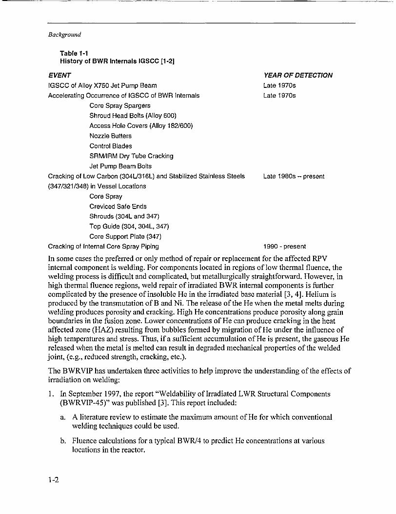
Table 1-1History of BWR Internals IGSCC [1-2]
EVENT YEAR OF DETECTIONIGSCC of Alloy X750 Jet Pump Beam Late 1970sAccelerating Occurrence of IGSCC of BWR Internals Late 1970s
Cracking of Low Carbon (304U316L) and Stabilized Stainless Steels Late 1980s - present(347/321/348) in Vessel Locations
Core SprayCreviced Safe EndsShrouds (304L and 347)Top Guide (304, 304L, 347)Core Support Plate (347)
Cracking of Internal Core Spray Piping 1990 - present
In some cases the preferred or only method of repair or replacement for the affected RPVinternal component is welding. For components located in regions of low thermal fluence, thewelding process is difficult and complicated, but metallurgically straightforward. However, inhigh thermal fluence regions, weld repair of irradiated BWR internal components is furthercomplicated by the presence of insoluble He in the irradiated base material [3, 4]. Helium isproduced by the transmutation of B and Ni. The release of the He when the metal melts duringwelding produces porosity and cracking. High He concentrations produce porosity along grainboundaries in the fusion zone. Lower concentrations of He can produce cracking in the heataffected zone (HAZ) resulting from bubbles formed by migration of He under the influence ofhigh temperatures and stress. Thus, if a sufficient accumulation of He is present, the gaseous Hereleased when the metal is melted can result in degraded mechanical properties of the weldedjoint, (e.g., reduced strength, cracking, etc.).
The BWRVIP has undertaken three activities to help improve the understanding of the effects ofirradiation on welding:
1. In September 1997, the report "Weldability of Irradiated LWR Structural Components(BWRVIP-45)" was published [3]. This report included:
a. A literature review to estimate the maximum amount of He for which conventionalwelding techniques could be used.
b. Fluence calculations for a typical BWR/4 to predict He concentrations at variouslocations in the reactor.
1-2
Background
c. A "Weldability map" based on the fluence calculations that indicated locations in thetypical BWR where conventional welding techniques could (and could not) be used.
2. The BWRVIP has negotiated with the Japanese Owners Group (JOG) for rights to useJapanese data on welding of irradiated materials. This information includes results ofexperiments conducted to define the maximum He concentration under which conventionalwelding may be used, as well as results of experiments with welding techniques that allowwelding on metal with higher He concentrations, (e.g., low heat input methods).
3. The BWRVIP, in collaboration with the NRC, has conducted a project to obtain samples ofirradiated metal from the jet pump riser brace pad location in three operating BWRs. Thesamples were analyzed to determine the He content, the initial B content, the fluence andother parameters.
The results of these three activities have been key sources of information for this Guideline.
1.2 Welding Guidelines Objective
The objective of this Guideline is to provide utilities with a methodology that can be used todetermine if weld repair to an irradiated component can be successfully performed and, if so,by which welding techniques. Note that the Guideline deals only with the aspects of performinga welded repair that are directly affected by the fact that the component has been irradiated.Other guidance for performing welded repairs that may be applicable is found in the BWRVIPRepair Design Criteria [5-13]
This Guideline has the following major elements:
1. Definition of Weldability Boundary - A "weldability boundary" is defined in Section 2. Thisboundary defines the locations in any BWR where He levels are sufficiently low (with a veryhigh degree of assurance) to allow a repair to be performed using conventional weldingtechniques. For locations that do not fall within the boundary, additional considerations arerequired to determine if welding can be successfully performed.
2. Methodology for Helium Determination - For locations outside the weldability boundary,one method for determining weldability requires that the He content of the metal be known.This requires a plant specific evaluation. The methodology for such an evaluation isdiscussed in Section 3.
3. Survey of Applicable Welding Techniques - While welding on irradiated components maynot be successful with conventional welding techniques; it has been successfully performedusing low heat input methods. Section 4 presents these welding methods and describes theconditions where each may be used.
4. Welding Guidelines - Based on Items 1, 2 and 3 above, a Guideline for welded repair ofirradiated components is presented in Section 5. The Guideline contains the methodology fordetermining which welding techniques may be used and presents guidance on requiredqualification tests, inspections, etc.
The flow chart shown in Figure 1-2 presents the overall logic of this Guideline.
1-3
Background
Content Deleted -
EPRI Proprietary Information
Figure 1-2Flow Chart for Determining Applicable Welding Techniques
1-4
Background
Content Deleted -EPRI Proprietary Information
Figure 1-2Flow Chart for Determining Applicable Welding Techniques (Continued)
1.3 References
1. R. M. Horn, et al., "Experience and Assessment of Stress Corrosion Cracking in L-GradeStainless Steel BWR Internals," Nuclear Engineering and Design, 174 (1997), p. 313.
2. "B TR Vessel and Internals Project, BWR Water Chemistry Guideline - 2000 Revision(BWRVIP-79), " EPRI TR-103515-R2, Palo Alto, CA, March 2000.
3. "B WR Vessel and Internals Project, WVeldability of Irradiated L WR Structural Components(BWIRVP-45)," EPRI TR-108707, Palo Alto, CA, September 1997.
4. A. L. Lund, "Underwater WVelding of Highly Irradiated In-Vessel Components of BoilingWYater Reactors -A Literature Revieiv," NUREG-16 16, paper presented at the Welding of
Irradiated materials Workshop, September 3-4, 1997, Charlotte, NC.
1-5
Background
5. "BYR Vessel and Internals Project, Internal Core Spray Piping and Sparger ReplacementDesign Criteria (B WRVIP-16), " EPRI report TR-106708, March 1997.
6. "BW'R Vessel and Internals Project, Internal Core Spray Piping and Sparger Repair DesignCriteria (BWVRVIP-19), " EPRI Report TR-106893, September 1996.
7. "BWZR Vessel and Internals Project, Top Guide/Core Plate Repair Design Criteria(BTRVIP-50), " EPRI Report TR-108722, May 1998.
8. "BJWR Vessel and Internals Project, Jet Pump Repair Design Criteria (BVRVIP-51), " EPRIReport TR-108718, May 1998.
9. "BWYR Vessel and Internals Project, Shroud Support and Vessel Bracket Repair DesignCriteria (BWRVIP-52), " EPRI Report TR-108720, June 1998.
10. "BWYR Vessel and Internals Project, Standby Liquid Control Line Repair Design Criteria(BTYRVIP-53), " EPRI Report TR- 108716, July 1998.
11. "BTYR Vessel and Internals Project, Lover Plenum Repair Design Criteria(BTWRVIP-55), " EPRI Report TR-108719, September 1998.
12. "BWVR Vessel and Internals Project, LPCI Coupling Repair Design Criteria(BJVRVIP-56), " EPRI Report TR-108717, November 1998.
13. "B R Vessel and Internals Project, Instrument Penetrations Repair Design Criteria(B WRVIP-57), " EPRI Report TR-108721, December 1998.
1-6
11
2DEFINITION OF WELDABILITY BOUNDARY
In this section, a He threshold for weldability is first established. Below the threshold,welding by conventional techniques may be used. Above the threshold, low heat input methodswill be required. Using this threshold and the results of a BWR fluence calculation, a genericweldability boundary is defined that is applicable to any BWR. Conventional welding may notbe successful on reactor components outside the weldability boundary. Additional evaluationsmust be performed if a welded repair is to be considered.
2.1 Helium Induced Cracking Background
Helium is produced by irradiation of metals via an (n, a) reaction where the metallic elementnucleus absorbs a neutron and emits an alpha particle () that is identical to a He nucleus [1].The He atom thus produced is very stable and remains in the metal indefinitely. In BWRs, thedominant method of production is by (n, a) reactions due to the interaction of thermal neutrons(E < 0.5eV) with boron (B) and nickel (Ni).
Boron is typically present as an impurity in stainless steels and Ni base alloys in concentrationsfrom <5 to >30 ppm. However, B is sometimes deliberately added to improve the hot workabilityof steel. Boron has two naturally occurring isotopes "1B and 10B where B is 19.9% of total B.Only ' 0B atoms undergo the (n,a) reaction with thermal neutrons.
Helium is often quantified in atomic percent rather than weight percent because it is such a lightelement. One weight percent of B in Fe is equivalent to 5.18 atomic percent. Since '°B is only19.9% of B, one weight percent B is equivalent to 1.03 atomic percent '0 B. Since every atom of'0 B will eventually transmute to 4He, one weight percent natural B can produce one atomicpercent He.
Depending on the exact alloy, Ni becomes a larger source of He at high thermal fluences >102 to10 ri n/cm . The behavior of Nickel is more complex than that of B since two transmutation stepsare required. Nickel 58 is 68. 1% of natural Ni and undergoes the following reactions withthermal neutrons:
5 8Ni + n -* 9Ni +y
59Ni + n -e 56Fe + 4He
Since 59Ni is not naturally occurring, the production rate of He is initially zero, but increases as59Ni accumulates. Unlike B, Ni is a major alloying element of BWR austenitic stainless steels,
2-1
Definition of Teldability Boundary
i.e., 8 to 14%, and, of course, Ni base alloys. Alloy 600 is 76% Ni. Therefore, the concentrationof He can increase to many thousands of atomic ppm (appm) provided there is sufficient thermalfluence. The thermal fluence threshold where He from Ni becomes greater than from B isapproximately 7 x 10²¹ for Type 304 stainless steel [1].
The preferred nucleation sites for He cracking are lattice inhomogeneities such as radiation-induced defects, precipitate interfaces, dislocations and, most importantly, grain boundaries [2].Since boron is an insoluble impurity element, it is expected that helium produced from boronwill be located preferentially at the grain boundaries, and since nickel is an alloying element andpresent throughout the matrix, helium produced from nickel will be found spread throughout thematrix.
Once He is produced above threshold levels, it can produce serious materials degradation duringa welding process since He is basically insoluble in metals. He diffuses through the matrix andsegregates at various defects and grain boundaries. Helium coalesces into bubbles that degradecohesion at grain boundaries and will eventually cause failure [1]. During welding, He bubblesare typically trapped in the fusion zone. The high temperatures allow rapid diffusion and rapidHe accumulation at grain boundaries. Damage occurs at the HAZ at lower He concentrations.The presence of a tensile stress due to volumetric contraction during solidification andsubsequent cooling allows the formation of larger He bubbles. Rapid growth of the He bubblesfed by rapidly diffusing He leads to grain boundary cracking in the HAZ.
2.2 Helium Concentration Cracking Threshold
A previous literature review indicated that the threshold for He induced weldability problems is1 appm [1] when conventional welding techniques are employed. It is the He concentration in themetal, not the thermal (or fast) fluence, per se, that determines whether He induced cracking ispossible. Higher He thresholds have been obtained when compressive stress or low heat inputweld overlays have been applied. For example, successful welds in irradiated material containing80 appm He (He from tritium decay) have been produced through the application of acompressive stress during welding. Although low heat input overlays have also been successfullymade in materials containing up to 85 appm He, the welds contained small amounts of underbeadcracking [1].
Content Deleted -
EPRI Proprietary Information
2.3 Calculation of Helium Content in a Typical BWR
Analyses have been performed to calculate He concentrations throughout a typical BWR/4(Susquehanna) for 1, 15 and 30 full power years [1]. These analytical results can be used to
2-2
Definition of WYeldability Boundary
define a generic weldability boundary. Table 2-1 shows the predicted He concentrations for amaterial containing 1 ppm B at various locations in the typical reactor. For alloys with differentB concentrations, the data are simply multiplied by the concentration of B. For example, if thematerial contained 5 ppm B, the amount of He generated would be increased by a factor of five.
Content Deleted -EPRI Proprietary Information
Table 2-2 summarizes the He data for a material containing 10% Ni. For alloys with differentNi concentrations, the data are simply multiplied by the Ni ratio. For example, if the materialcontained 12% Ni, the amount of He generated would be increased by a factor of 1.2.
Content Deleted -EPRI Proprietary Information
2.4 Bounding Helium Evaluation
To establish a generic weldability boundary, a worst-case calculation was performed usingconservative values of B and Ni concentrations. A "worse-case" Type 316 stainless steelcontaining a specification maximum allowable Ni content of 14 % plus a high end Bconcentration of 20 ppm is assumed. The 1999 average B for Type 316 stainless steel was16 ppm [2]. Although Type 304 stainless steel has been used more commonly for BWRinternals, Type 316 stainless steel was used for this example due to its higher Ni content(10-14% versus 8 - 10.5 %) and typically higher average B content (16 ppm versus 12 ppmfor 1999) than Type 304 stainless steel.
Table 2-3 presents the Helium concentrations predicted using the Susquehanna calculations withthe conservative values of B and NiContent Deleted -
Based on the results of the worst-case evaluation performed above and shown in Table 2-3, a"generic weldability boundary" may be defined.
Content Deleted -
EPRI Proprietary Information
Using this criterion, a review of Table 2-3 indicates that the following locations will be weldablein any BWR without consideration of helium content:
Content Deleted -EPRI Proprietary Information
2-3
Definition of JVeldability Boundary
Content Deleted -
EPRI Proprietary Information
These locations define the generic weldability boundary. Other components not specificallymentioned, but lying in close proximity to those listed, are also considered weldable.
This model is consistent with the actual RPV welding experience since the following internalcomponents have been successfully weld repaired in BWRs:
Core spray line
Feedwater sparger pipe
Jet pump adjusting screw tack welds
Steam dryer
2-4
Definition of JVeldability Boundary
Table 2-1Atomic ppm He from Only 1 ppm B as a Function of Component and Location Based onSusquehanna
Content Deleted -
EPRI Proprietary Information
2-5
Definition of IVeldability Botndary
Table 2-2Atomic ppm He from Only 10% Ni as a Function of Component and Location Based onSusquehanna
Content Deleted -EPRI Proprietary Information
2-6
Definition of TVeldability Boundary
Table 2-3Total Atomic ppm He from 20 ppm B and 14% Ni as a Function of Component and LocationBased on Susquehanna
Content Deleted -EPRI Proprietary Information
2-7
Definition of JWeldability Boundary
2.6 References
1. "BWYR Vessel and Internals Project, eldab ility of Irradiated L R Structural Components(BTRVIP-45)," EPRI TR-108707, Palo Alto, CA, September 1997.
2. W. T. Wood e-mail to B. M. Gordon, "Boron Concentrations of Types 304 and 316 StainlessSteel," June 1, 2000.
2-8
3DETERMINATION OF HELIUM CONTENT
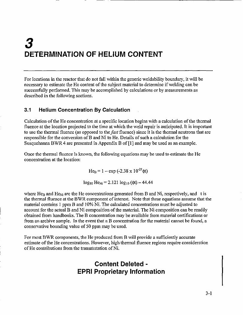
For locations in the reactor that do not fall within the generic weldability boundary, it will benecessary to estimate the He content of the subject material to determine if welding can besuccessfully performed. This may be accomplished by calculations or by measurements asdescribed in the following sections.
3.1 Helium Concentration By Calculation
Calculation of the He concentration at a specific location begins with a calculation of the thermalfluence at the location projected to the time at which the weld repair is anticipated. It is importantto use the thermal fluence (as opposed to thefast fluence) since it is the thermal neutrons that areresponsible for the conversion of B and Ni to He. Details of such a calculation for theSusquehanna BWR 4 are presented in Appendix B of [1] and may be used as an example.
Once the thermal fluence is known, the following equations may be used to estimate the Heconcentration at the location:
HeB = 1 - exp (-2.38 x 10-214,t)
logio HeNi = 2.121 logio (t) - 44.44
where HeB and HeNi are the He concentrations generated from B and Ni, respectively, and t isthe thermal fluence at the BWR component of interest. Note that these equations assume that thematerial contains 1 ppm B and 10% Ni. The calculated concentrations must be adjusted toaccount for the actual B and Ni composition of the material. The Ni composition can be readilyobtained from handbooks. The B concentration may be available from material certifications orfrom an archive sample. In the event that a B concentration for the material cannot be found, aconservative bounding value of 50 ppm may be used.
For most BWR components, the He produced from B will provide a sufficiently accurateestimate of the He concentrations. However, high thermal fluence regions require considerationof He contributions from the transmutation of Ni.
Content Deleted -EPRI Proprietary Information
3-1
Determination of Helitm Content
Content Deleted -EPRI Proprietary Information
3.2 Sample Removal
The most accurate method to obtain He concentration is by performing laboratory measurementson a sample removed from the target component. Helium (as well as thermal fluence, boroncontent, and other parameters) can be determined from small shavings removed from thecomponent. Acceptable methods for removing and analyzing these samples are described in[2]. The required sample size is approximately 50 milligrams and the accuracy of the Hedetermination is approximately one percent.
Content Deleted -EPRI Proprietary Information
In one sense sample removal is superior to calculation as a method for deternining heliumcontent in that it eliminates uncertainties and conservatisms that are inherent in the fluencecalculation process.
3.3 References
1. "BTYR Vessel and Internals Project, JVeldability of Irradiated L TR Structural Coniponents(BWVRVIP-45)," EPRI TR-108707, Palo Alto, CA, September 1997.
2. "BTYRVIP-96: BYR Vessel and Internals Project, Sanpling and Analysis Guideline forDetermining Heliumiz Content of Reactor Internals," EPRI 1003019, Palo Alto, CA 2001.
3-2
1
4APPLICABILITY OF WELDING TECHNIQUES
4.1 Introduction
A number of sources were used to establish the weldability of irradiated materials using variouswelding techniques. These include the BWRVIP literature survey conducted in 1997 [1], theJOG data recently obtained by the BWRVIP [2], as well as over one hundred articles identifiedfrom Metal Abstracts (ASM), Energy Science and Technology (DOE), USG/NTIS andEngineering Index and Weldasearch.
Following is a brief summary of the test results that were evaluated. A more complete discussionmay be found in [2].
4.2 Applicability Of Welding Techniques
4.2.1 Weldability Boundary
Figure 4-1 summarizes the effect of He concentration on cracking as a function of heat inputbased on JOG, BWRVIP-45 and other studies for Type 304, 304L, 316 and 316L stainless steeland for Alloy 600. The points are annotated to show which conditions resulted in cracking andwhich did not. For some tests, results indicate that small He "bubbles" were observed. Due totheir spherical shape, small diameter (<100 nm) and spacing (1 pm), He bubbles were notconsidered an engineering concern and were not treated as cracks.
A weldability border between the cracking and no cracking points was constructed on Figure 4-1for the stainless steel data. The most conservative values were used to anchor the borders with aminimum of a factor of two additional margins based on He content. For example, if no Hecracking was identified at 1 appm He and cracking was identified at 2 appm at the same heatinput, the borderline was constructed to be at or below the 0.5 appm point. Figure 4-1 indicatesthat successful welds can be obtained on irradiated material at relatively high He contents if theappropriate technique is selected. Content Deleted -
EPRI Proprietary InformationIt is important to note that, even if the He content of a component is on the "cracking" side of theweldability boundary, it is not necessarily true that welding cannot be performed by a suitablewelding technique. This concept is supported by the fact that there were several successful weldsperformed at higher He concentrations (open points to the right of the line).
4-1
Applicability of JVelding Techniques
Additionally, the majority of the data shown in Figure 4-1 was obtained from specimens thatwere shield welded inside a habitat. It is expected that water-backed welded (or underwaterwelded) components would be characterized by superior results than the results obtained inside ahabitat, i.e., water-backed welding should allow welding at higher heat inputs and/or higher Hecontents due to the quenching effects of the adjacent water.
Due to the paucity of data on Alloy 600, no general boundary between cracking and no crackingcould be defined. Utilities may, however, find the data useful in making plant specific decisionsregarding the weldability of those materials.
4.2.2 Transmutation Helium versus Tritium Decay Data
A technique for producing He in materials that does not require irradiation is often used inlaboratory studies. Since the isotope of hydrogen, tritium, decays to 3He, tritium can be utilizedto study the effects of He on welding in irradiated material. This technique known as the "tritiumtrick" method and consists of diffusing tritium into a metal at elevated temperatures andpressures. The metal is then cooled and aged at cryogenic temperatures until the desiredconcentration of He is formed. It is then heated in a vacuum to permit the tritium to diffuse outleaving the He. Although the 12.3 year tritium half life means a slow He doping process, the useof sufficient amounts of tritium allows significant He generation to be achieved. The greatestadvantage of this technique is that the material is not irradiated and thus not activated. Thiseliminates the need for hot cells in performing tests. This "helium doping" methodology is oftenused in testing materials simulating He damage due to irradiation.
However, implanting He by irradiation or tritium can result in different levels of cracking in thematerial after welding [3]. This difference can be explained by the difference in He locations.Irradiation of the material results in transmutation of B at the grain boundaries and transmutationof Ni homogeneously throughout the material. Tritium decay will only result in a homogeneousdistribution of He with no concentration of He at the grain boundaries. These differences arecritical in interpreting test results.
Irradiated material is also metallurgically damaged, i.e., high dislocation densities, dislocationloops, vacancies, etc. Such damage to the matrix has a role in subsequent material performance.No such irradiation damage exists in tritium decay treated materials.
Due to these differences, data obtained using the tritium trick method that are shown onFigure 4-1 with the notation "TD" (tritium decay) and were not considered in establishing theweldability boundary.
4-2
Applicability of iVelding Techniques
Content Deleted -
EPRI Proprietary Information
Figure 4-1Effect of He and Heat Input on the Weldability of Stainless Steel and Alloy 600 [4]
4-3
Applicability of WVelding Techniques
4.2.3 Successful Industry Experience with Welding of Irradiated Material
Numerous tests have been performed to investigate suitable techniques for successfully weldingirradiated stainless steel. Samples of those tests are described in the following paragraphs.
Westinghouse Savannah River has developed a low penetration gas metal arc (GMAW) overlaywelding technique that minimized cracking in irradiated Type 304 stainless steel that contained10 appm He from tritium decay [3-4]. Surface cracking that was present in conventional weldsmade on the same steel at the same and lower He concentrations was eliminated. Underbeadcracking was minimal compared to conventional welding methods. This overlay techniqueprovides a potential method for repair or modification of irradiated materials.
Content Deleted -EPRI Proprietary Information
4-4
Applicability of WVelding Techniques
4.3 Summary of Advanced Welding Techniques
Based on the welding data presented in this guideline, as summarized in Figure 4-1, it is clearlypossible to weld repair highly irradiated austenitic materials using a number of techniques. Thesetechniques include:
1. Low heat input GTAW, also referred to as TIG.
2. Low penetration GMAW or (GMAW-S)
3. Laser beam welding (LBW)
In some instances, successful welding may require the use of autogenous techniques.
Although there is no information currently available in the open literature, other weldingtechniques may also be applicable provided suitable qualifications are performed.
4.4 References
1. "BWVR Vessel and Internals Project, JlVeldability of Irradiated L WR Strulcttral Components(BWVRVIP-45)," EPRI TR-108707, Palo Alto, CA, September 1997.
2. "B PR Vessel and Internals Project, B WR VIP-98: Technical Basis for Guidelines forPerforming eld Repairs to Irradiated BWR Internals)," EPRI TR-1006385, Palo Alto, CA,2001.
3. W. R. Kanne, et al. "Welding Irradiated Stainless Steels," Journal of Nuclear Materials, Vol.225, August 1995, p. 69.
4. W. R. Kanne, et al. "Weld Repair of Irradiated Materials," Materials Characterization, Vol.43, August- September 1999, p. 203 .
5. S. Nishimura, et al., "YAG Laser Welding of Neuttron Irradiated Stainless Steels," Journal ofNuclear Materials, Vol. 258-263 (Part B), October 1998, p. 2002.
6. C. A. Wang, et al., "Welding of Irradiated Steels," Journal of Nuclear Materials, Vol. 233-237, October 1996, p. 213.
7. C. A. Wang, et al., "The Effect of an Applied Stress on the Welding of Irradiated Steels,"Journal of Nuclear Materials, Vol. 239, November 1996, p. 85.
8. W. R. Kanne, Jr. et al, "Repair WYelding of Irradiated 304 Stainless Steel," paper presented atMaintenance and Repair Welding In Power Plants V, November 30 - December 2, 1994,Orlando, FL, published in Proceedings, American Welding Society, Miami, FL, 1995, p. 129.
9. E. A. Franco-Ferreira and W. R. Kanne, Jr., "Remote Reactor Repair: Avoidance of Heliuim-Induiced Cracking Using GMAW," Welding Journal, Vol. 71, No. 2, February 1992, p. 43.
10. K. Tsuchiya, H. Kawamura and R. Oyamada, "Joining Technology Development ofAdvanced Materials/SS304 by Friction Welding," JAERI Technical Report 95-017.
4-5
5WELDING GUIDELINES SUMMARY
Section 5.1 presents a simple guideline for determining the weldability of a component based onthe considerations discussed in previous sections. If the component is determined to be weldable,certain qualifications, analyses and inspections are required. These are presented in Sections 5.2through 5.4.
5.1 Weldability Determination
The process for determining whether a weld repair can be successfully performed is shownschematically in the flow chart presented in Figure 1-2. It consists of the following steps:
1 Determine if the component lies within the generic weldability boundary as defined inSection 2. If so, welding may be performed by conventional means without regard for effectsof irradiation.
2 Content Deleted -EPRI Proprietary Information
3 If the component is outside the boundary and the thermal fluence exceeds lxlO 8 n/cm2 , thentwo options are available for determining weldability:
a. Weldability Determination by Estimation of He Concentration
Content Deleted -EPRI Proprietary Information
b. Weldability Determination by Test
Content Deleted -EPRI Proprietary Information
5-1
17elding Guidelines Sunrnary
Content Deleted -EPRI Proprietary Information
5.2 Additional Considerations
Welding on irradiated austenitic materials in nuclear power plants may involve special issuesrelated to the irradiation-induced degradation of the material. The production of He in the alloyas a result of neutron exposure may affect the weldability of the component depending upon theamount of He that has been produced and the welding heat input employed. This section of thisreport provides guidance related to additional controls that are required to weld on these highlyirradiated components. It is the intention of the BWRVIP for these controls to be implementedfor both ASME Code and non-Code vessel internals components in the BWR.
5.2.1 Required Qualification Tests
The ASME Code, Section IX, provides the essential and non-essential variables in its weldprocedure specifications (WPS) and procedure qualification records (PQR) that give the criteriafor welding on materials in power plant applications. These guidelines do not provide foradditional requirements in the event that the material has become susceptible to specificenvironmental effects that would compromise the weldability of the material. The guidance forproviding additional welding requirements when performing specialized welding, such asundervater welding, falls to the individual book Section of the Code for which the constructionis performed. In the case of nuclear power plants, Section XI is the responsible book section forin-service repairs or replacements, and therefore, it is Section XI that should provide the specificguidance for such repairs. Section XI does not, however, provide specific guidance with respectto welding on irradiated materials.
This report has described three regimes of varying helium concentration where welding may ormay not be possible. A generic weldability boundary has been defined within which the effectsof irradiation are benign and conventional welding may be used. A second regime is identified inwhich welding is possible provided the heat input is controlled. And a third regime exists wherewelding at these He levels has not been completely demonstrated, and a demonstration will berequired to show that successful welding on the specific component can be performed.
The following paragraphs describe the required qualifications for welding in each of these threeregimes. In some cases, the requirements are in addition to the requirements of the Code. ForASME Code repairs, it is anticipated that the additional welding requirements identified belowcan be represented as "supplementary essential variables" and be incorporated into the Plantwelding program when appropriate.
Content Deleted -EPRI Proprietary Information
5-2
Welding Guidelines Summary
Content Deleted -EPRI Proprietary Information
5-3
[Velding Guidelines Summary
Content Deleted -
EPRI Proprietary Information
5.2.2 Required Inspections
5.2.2.1 Kinetics of He Cracking
It is believed that the detrimental effects of He would be seen immediately, i.e., it is not a timedependent reaction, and that, if a component was welded without any evidence of cracking,cracking would not appear at a later date.
Underbead cracking is a concern and may be difficult to detect. Welding studies have indicatedthat while overlay welds eliminated weld toe cracking that had been observed in conventionalwelds, both conventional and overlay welds can suffer underbead cracking [1]. Underbeadcracking is typically confined to within one or two grains of the weld interface.
However, since underbead cracking is embedded in the material, remote from the weld toe andnot exposed to the environment, underbead cracking is more of a net section concern and mustbe analyzed to assure structural integrity. Since the weld repair itself is designed to address anynet section or embedded flaw concern, this evaluation should be rather straightforvard. Anyweld toe cracking should be repaired by grinding and repair.
5.2.2.2 ASME Code Requirements
The ASME Code requires that following the detection and repair of a flaw, the inspection to beperformed should be the same as the inspection that identified the flaw. In the case of welding onirradiated materials, i.e., those materials for which the level of He in the alloy produces a risk forHAZ cracking, the Code rules are inadequate. Whereas the weld repair may repair or remove theflaw that necessitated the repair, the actual weld may create new defects in the weld HAZsproduced on each toe of the weld. In addition, the repair may also produce imbedded crackingbeneath the weld repair in the original base metal. As a result of this additional potentialcracking, additional NDE testing is required to demonstrate that no cracking detrimental to thefuture performance of the component remains.
Content Deleted -EPRI Proprietary Information
5-4
WVelding Guidelines Summary
Content Deleted -EPRI Proprietary Information
5.2.3 Required Analyses
No additional analyses are required by the rules of the ASME Code for these irradiated andwelded components. However, an analysis may be used to demonstrate the acceptability ofcertain observed flaws. Paragraph IWB-3600 of Section XI of the ASME Code provides for theacceptance of flaws in a component if one can justify that the design safety margin has not beencompromised for the ensuing operating interval. (Note that paragraph IWB-3600 specificallyaddresses flaws found during in-service inspections. For the current purpose, flaws that are foundduring a post-weld inspection will be addressed by the same paragraph.) This Code provisionallows the utility Owner to accept a limited distribution of defects that could occur during theweld repair allowing for continued operation of the component. These include embedded defects,where no additional driving mechanism is available, since the environment cannot get to theflaw, and the stress has been reduced to an acceptable level due to the weld repair. For toe cracksassociated with high He level HAZ cracking, removal of these surface cracks and analysis of theslight depression may allow for continued successful operation of the component. Additionally,depending upon the location and severity of the He induced HAZ cracking, the defect may bebenign and allow for additional operation with the defect in place. Each of these cases wouldneed to be evaluated individually, and a decision made accordingly.
5.3 References
1. "B WR Vessel and Internals Project, WVeldability of Irradiated L WR Structural Components(BJJ'RVIP-45)," EPRI TR-108707, Palo Alto, CA, September 1997.
5-5
About EPRITarget:
Nuclear Power EPRI creates science and technology solutions for
the global energy and energy services industry. U.S.
electric utilities established the Electric Power
Research Institute in 1973 as a nonprofit research
consortium for the benefit of utility members, their
customers, and society. Now known simply as EPRI,
the company provides a wide range of innovative
products and services to more than 1000 energy-
related organizations in 40 countries. EPRI's
multidisciplinary team of scientists and engineers