Date post: | 21-Dec-2015 |
Category: |
Documents |
View: | 213 times |
Download: | 0 times |
Project: Anomalous Dispersion
John H. Cushman1, Natalie Kleinfelter1, Monica Moroni2
1Department of Earth and Atmospheric Sciences and Department of Mathematics, Purdue University, West Lafayette, IN 47907 (e-mail: [email protected]) 2Department of Hydraulics, Transportations and Roads, University of Rome “La Sapienza” – via Eudossiana 18, 00184 Rome (Italy) (e-mail: [email protected])
“Ingredients” for image analysis
The fluid under investigation and the test section have to be transparent: mono-phase and multi-phase systems
The fluid has to be seeded with tracer particles with the following features: same density as water and highly reflecting
One or more cameras, a high power light source, an acquisition and digitalization system and image analysis system are required
Applications
• Fully developed turbulent channel
• Porous media
• Convective boundary layer
• Subduction
• Multi-dune channel
• Bacteria motion
• Ventricular flow
Turbulent channel flow (d= 2 cm, x/d = 80, z/d = 10)
The experimental set-up
Tracers (p/f = 1.06, dP = 40 mm)
Applications
• Fully developed turbulent channel
• Porous media
• Convective boundary layer
• Subduction
• Multi-dune channel
• Bacteria motion
• Ventricular flow
Applications
• Fully developed turbulent channel
• Porous media
• Convective boundary layer
• Subduction
• Multi-dune channel
• Bacteria motion
• Ventricular flow
Applications
• Fully developed turbulent channel
• Porous media
• Convective boundary layer
• Subduction
• Multi-dune channel
• Bacteria motion
• Ventricular flow
The experimental apparatus
Camera (top view)
Camera (lateral view)
x
z
y
Plate width- 30 cm- 20 cm- 10 cm
Applications
• Fully developed turbulent channel
• Porous media
• Convective boundary layer
• Subduction
• Multi-dune channel
• Bacteria motion
• Ventricular flow
The experimental apparatus
Longitudinal section (dimensions in mm)
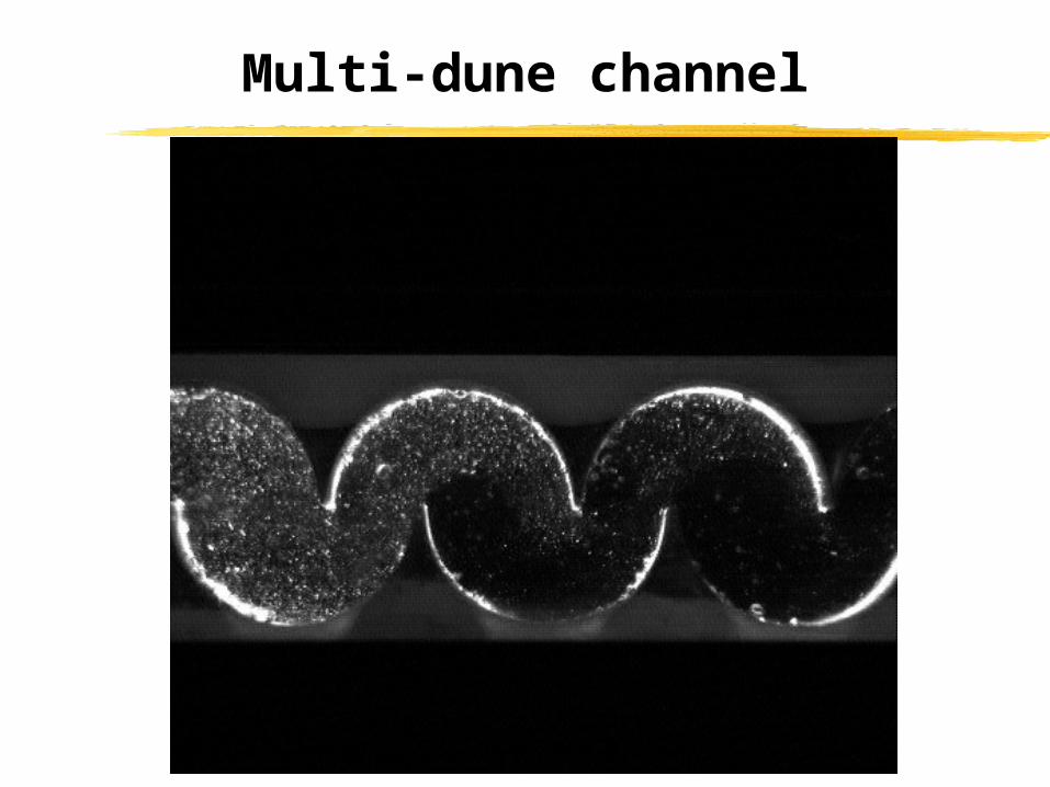
A multi-dune is a device constructed from a sequence of closed parallel cylindrical tubes welded together in plane. The complex is sliced down its lateral mid-plane and the lower half is shifted laterally and then fixed relative to the upper half.
Flo
w
in
Flo
w
ou
t
300
8
12 4
30
20
8
15
30 60
30
R1 R2 R3 R4 R5 R6 R7 R8
C1 C3 C4 C5 C6 C7 C8
Applications
• Fully developed turbulent channel
• Porous media
• Convective boundary layer
• Subduction
• Multi-dune channel
• Bacteria motion
• Ventricular flow
Applications
• Fully developed turbulent channel
• Porous media
• Convective boundary layer
• Subduction
• Multi-dune channel
• Bacteria motion
• Ventricular flow
Ventricle
Tank
Laser
Camera
Mirror
PistonMotor
Compliance Head losses
Investigation of Ventricular Flow