41
An Investigation into the Effects of Turbofan Aircraft Nacelle Placement on Aircraft Drag Philip Brown (Y3292943) T450 The Engineering Project Open University September 2013
| Date post: | 24-Jan-2017 |
| Category: |
Documents |
| Upload: | philip-brown-amimeche |
| View: | 230 times |
| Download: | 0 times |
An Investigation into the Effects of Turbofan Aircraft Nacelle Placement on Aircraft Drag
Philip Brown (Y3292943)
T450 The Engineering ProjectOpen University
September 2013

T450: The Engineering Project - An investigation into the effects of turbofan aircraft nacelle placement on aircraft drag
Special Thanks
Thank you to those who helped me in getting this project as far as I did
Claire Shott, my long-suffering girlfriendDr Karl Odie, good friend and help on starting the project
Malcolm Swannell, a great tutorThe CFD-Online Forums, helping me with my OpenFOAM problems
The GMsh mailing list, helping me with GMsh
Philip Brown (Y3292943)
T450: The Engineering Project - An investigation into the effects of turbofan aircraft nacelle placement on aircraft drag
Summary
Aim
The aim of the project is to analyse the drag characteristics of three different configurations of engine nacelle placement (under-wing, in-wing and on-wing) on the Boeing 737-800 wing. This is in order to determine which configuration provides the greatest efficiency with respect to drag.
Outline
The project was conducted through a series of refinements of drag determined by various methods. These were: 1) Flat-plate approximation calculations of drag (i.e. skin friction only) 2) Aerofoil drag (based on aerofoil sections) determined using SimpleFoam (an OpenFOAM solver). 3) Full wing drag (based on aerofoil sections and dimensions of the real Boeing 787-800 wing) determined using SimpleFoam (an OpenFOAM solver).
Results
Unfortunately, the results are inconclusive due to a lack of time to complete the full wing simulations. The flat plate approximation favours the in-wing configuration whilst the aerofoil drag calculations favoured the over and under-wing configurations.
Section Word Count: 145
Philip Brown (Y3292943)
T450: The Engineering Project - An investigation into the effects of turbofan aircraft nacelle placement on aircraft drag
Table of ContentsSummary................................................................................................................................................................................. 2
1. Introduction........................................................................................................................................................................ 2
1.1 Project Background.................................................................................................................................................................2
1.2 Project Development (including Literature Review)................................................................................................................3
1.3 Projects Aim and Objectives....................................................................................................................................................5
2. Boundary Conditions Used in Calculations and Simulations..................................................................................................6
2.1 Calculated Conditions.............................................................................................................................................................6
2.2 Tabulated Conditions..............................................................................................................................................................7
3. Determination of Drag of Simplified Wing Configurations from Calculations.........................................................................8
3.1 Flat Plate Approximation........................................................................................................................................................8
3.2 Approximation Based on SimpleFoam CD Values for 2D Aerofoils...........................................................................................9
4. Determination of Drag of Wing Configurations Using Computational Fluid Dynamics..........................................................12
4.1 Control Volume.....................................................................................................................................................................12
4.2 Full Wing...............................................................................................................................................................................12
4.3 Solver Choices.......................................................................................................................................................................13
5. Analysis and Findings......................................................................................................................................................... 14
5.1 Flat Plate Approximation......................................................................................................................................................14
5.2 2D Aerofoil Drag...................................................................................................................................................................14
5.3 Full Wing...............................................................................................................................................................................14
5.4 Points of Continuation..........................................................................................................................................................14
5.4 Conclusion.............................................................................................................................................................................14
6. Further Analysis – How to Expand on This Project.............................................................................................................. 15
6.1 Structural Analysis................................................................................................................................................................15
6.2 Systems Analysis...................................................................................................................................................................15
6.3 Computational Aeroacoustics (CAA) Modelling....................................................................................................................16
References............................................................................................................................................................................ 17
Appendix............................................................................................................................................................................... 20
Proposal......................................................................................................................................................................................20
Flat-Plate Approximation Calculations.......................................................................................................................................20
2D Aerofoil..................................................................................................................................................................................22
Mesh Development.....................................................................................................................................................................24
Further Analysis..........................................................................................................................................................................25
Glossary................................................................................................................................................................................ 26
Nomenclature.............................................................................................................................................................................26
1. Introduction
T450: The Engineering Project - An investigation into the effects of turbofan aircraft nacelle placement on aircraft drag
1.1 Project Background
Modern large passenger aircraft strive to be as efficient as possible, be it in use of materials, engine management systems or bigger aircraft. One thing that hasn’t changed is the placement of aircraft engine nacelles.
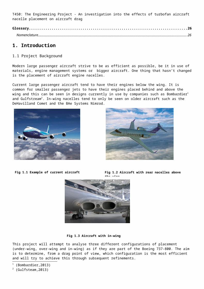
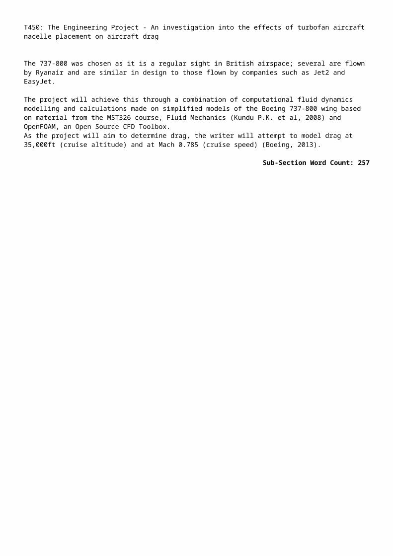
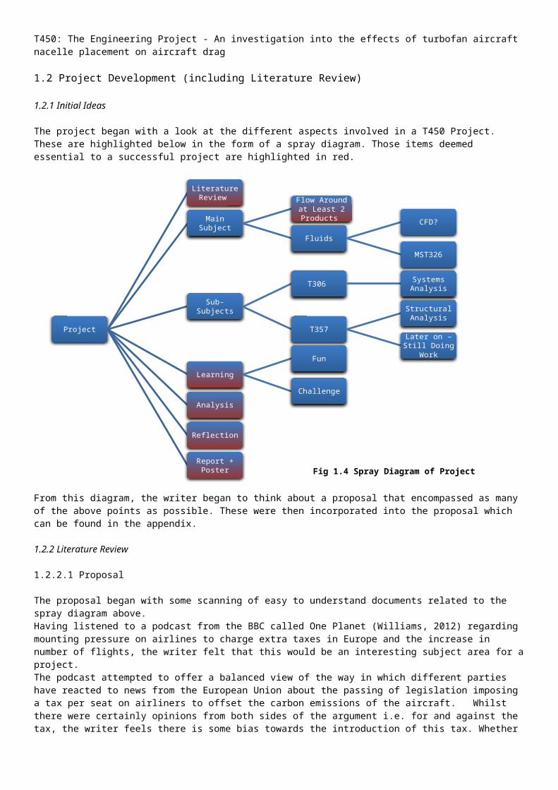
Current large passenger aircraft tend to have their engines below the wing. It is common for smaller passenger jets to have their engines placed behind and above the wing and this can be seen in designs currently in use by companies such as Bombardier1 and Gulfstream2. In-wing nacelles tend to only be seen on older aircraft such as the DeHavilland Comet and the BAe Systems Nimrod.
This project will attempt to analyse three different configurations of placement (under-wing, over-wing and in-wing) as if they are part of the Boeing 737-800. The aim is to determine, from a drag point of view, which configuration is the most efficient and will try to achieve this through subsequent refinements.
The 737-800 was chosen as it is a regular sight in British airspace; several are flown by Ryanair and are similar in design to those flown by companies such as Jet2 and EasyJet. The project will achieve this through a combination of computational fluid dynamics modelling and calculations made on simplified models of the Boeing 737-800 wing based on material from the MST326 course, Fluid Mechanics (Kundu P.K. et al, 2008) and OpenFOAM, an Open Source CFD Toolbox. As the project will aim to determine drag, the writer will attempt to model drag at 35,000ft (cruise altitude) and at Mach 0.785 (cruise speed) (Boeing, 2013).
Sub-Section Word Count: 257
1 (Bombardier,2013)2 (Gulfsteam,2013)
Fig 1.1 Example of current aircraft configuration Fig 1.2 Aircraft with rear nacelles above the wing
Fig 1.3 Aircraft with in-wing nacelles
T450: The Engineering Project - An investigation into the effects of turbofan aircraft nacelle placement on aircraft drag
1.2 Project Development (including Literature Review)
1.2.1 Initial Ideas
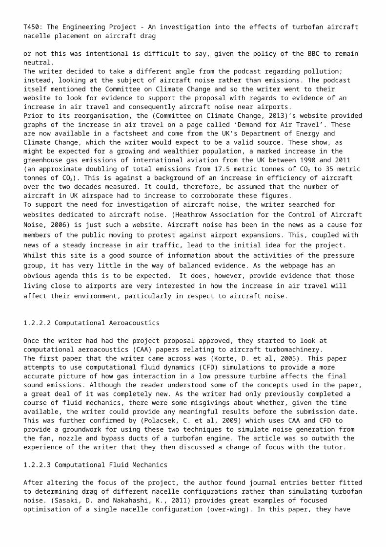
The project began with a look at the different aspects involved in a T450 Project. These are highlighted below in the form of a spray diagram. Those items deemed essential to a successful project are highlighted in red.
From this diagram, the writer began to think about a proposal that encompassed as many of the above points as possible. These were then incorporated into the proposal which can be found in the appendix.
1.2.2 Literature Review
1.2.2.1 Proposal
The proposal began with some scanning of easy to understand documents related to the spray diagram above. Having listened to a podcast from the BBC called One Planet (Williams, 2012) regarding mounting pressure on airlines to charge extra taxes in Europe and the increase in number of flights, the writer felt that this would be an interesting subject area for a project.The podcast attempted to offer a balanced view of the way in which different parties have reacted to news from the European Union about the passing of legislation imposing a tax per seat on airliners to offset the carbon emissions of the aircraft. Whilst there were certainly opinions from both sides of the argument i.e. for and against the tax, the writer feels there is some bias towards the introduction of this tax. Whether or not this was intentional is difficult to say, given the policy of the BBC to remain neutral.The writer decided to take a different angle from the podcast regarding pollution; instead, looking at the subject of aircraft noise rather than emissions. The podcast itself mentioned the Committee on Climate Change and so the writer went to their website to look for evidence to support the proposal with regards to evidence of an increase in air travel and consequently aircraft noise near airports. Prior to its reorganisation, the (Committee on Climate Change, 2013)’s website provided graphs of the increase in air travel on a page called ‘Demand for Air Travel’. These are now available in a factsheet and come from the UK’s Department of Energy and Climate Change, which the writer would expect to be a valid source. These show, as might be expected for a growing and wealthier population, a marked increase in the greenhouse gas emissions of international aviation from the UK between 1990 and 2011 (an approximate doubling of total emissions from 17.5 metric tonnes of CO2 to 35 metric tonnes of CO2). This is against a background of an increase in efficiency of aircraft
Project
Literature Review
Main Subject
Flow Around at Least 2 Products
Fluids
CFD?
MST326
Sub-Subjects
T306 Systems Analysis
T357
Structural Analysis
Later on – Still Doing Work
Learning
Fun
Challenge
Analysis
Reflection
Report + Poster Fig 1.4 Spray Diagram of Project
T450: The Engineering Project - An investigation into the effects of turbofan aircraft nacelle placement on aircraft drag
over the two decades measured. It could, therefore, be assumed that the number of aircraft in UK airspace had to increase to corroborate these figures. To support the need for investigation of aircraft noise, the writer searched for websites dedicated to aircraft noise. (Heathrow Association for the Control of Aircraft Noise, 2006) is just such a website. Aircraft noise has been in the news as a cause for members of the public moving to protest against airport expansions. This, coupled with news of a steady increase in air traffic, lead to the initial idea for the project. Whilst this site is a good source of information about the activities of the pressure group, it has very little in the way of balanced evidence. As the webpage has an obvious agenda this is to be expected. It does, however, provide evidence that those living close to airports are very interested in how the increase in air travel will affect their environment, particularly in respect to aircraft noise.
1.2.2.2 Computational Aeroacoustics
Once the writer had had the project proposal approved, they started to look at computational aeroacoustics (CAA) papers relating to aircraft turbomachinery. The first paper that the writer came across was (Korte, D. et al, 2005). This paper attempts to use computational fluid dynamics (CFD) simulations to provide a more accurate picture of how gas interaction in a low pressure turbine affects the final sound emissions. Although the reader understood some of the concepts used in the paper, a great deal of it was completely new. As the writer had only previously completed a course of fluid mechanics, there were some misgivings about whether, given the time available, the writer could provide any meaningful results before the submission date. This was further confirmed by (Polacsek, C. et al, 2009) which uses CAA and CFD to provide a groundwork for using these two techniques to simulate noise generation from the fan, nozzle and bypass ducts of a turbofan engine. The article was so outwith the experience of the writer that they then discussed a change of focus with the tutor.
1.2.2.3 Computational Fluid Mechanics
After altering the focus of the project, the author found journal entries better fitted to determining drag of different nacelle configurations rather than simulating turbofan noise. (Sasaki, D. and Nakahashi, K., 2011) provides great examples of focused optimisation of a single nacelle configuration (over-wing). In this paper, they have already come to the assumption that, from a noise perspective, over-wing is the optimal position. Interestingly, their optimised nacelle seems to have a negative drag coefficient, which may or may not be attributed to its position. Another paper of significance is (Destarac, D. and Van, D.V., 2004). In this paper, the author’s aim to determine the equations of drag for a standard aircraft setup (under-wing configuration) during powered flight. Whilst these could have formed the basis of the project, the complexity of the calculus alongside learning how to use CFD packages made this unrealistic in the time frame available.
1.2.3 Project Evolution
The focus of this project has changed somewhat from when it first started, back in February 2013. Prior to completing the literature review, the writer hoped to provide an insight into the issues of airport noise, particularly the effect on surrounding neighbourhoods. However, since the writer had not done any computational aeroacoustics previously and as the task of determining how OpenFOAM worked became a challenge in itself, it was decided to change to something more in line with the course material on fluid dynamics. Given the time limit, the breadth of the project has also been reduced so that any analysis not related to the fluid mechanics part of the project has been left to others reading to perhaps pick up.
Sub-Section Word Count: 1036
T450: The Engineering Project - An investigation into the effects of turbofan aircraft nacelle placement on aircraft drag
1.3 Projects Aim and Objectives
1.3.1 Project Aim
The aim of the project is to analyse the drag characteristics of three different configurations of engine nacelle placement on a Boeing 737-800 wing to determine which the most efficient configuration is.
1.3.2 Project Objectives
1. To provide an estimation of drag based on simplified models of the wing in different configuration via a flat-plate approximation of drag and an estimation of the drag based on CFD testing of the aerofoils that make up the wing and nacelle.
2. To determine the drag characteristics of each nacelle configuration using the open source CFD toolbox, OpenFOAM.
3. To provide an analysis of the various methods with a view to determining the most efficient configuration with respect to drag.
4. To provide an analysis of means to expand on this report for a more holistic view on nacelle placement.
Sub-Section Word Count: 140
Section Word Count: 1433
T450: The Engineering Project - An investigation into the effects of turbofan aircraft nacelle placement on aircraft drag
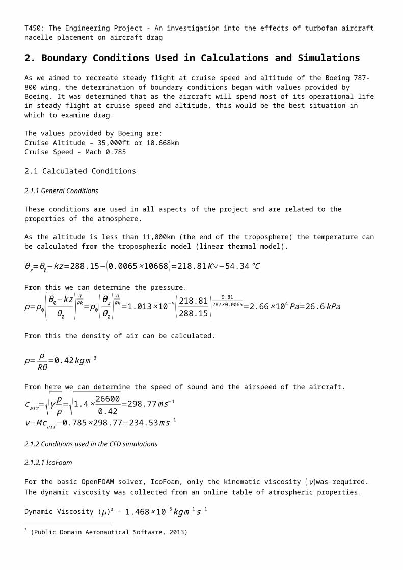
2. Boundary Conditions Used in Calculations and SimulationsAs we aimed to recreate steady flight at cruise speed and altitude of the Boeing 787-800 wing, the determination of boundary conditions began with values provided by Boeing. It was determined that as the aircraft will spend most of its operational life in steady flight at cruise speed and altitude, this would be the best situation in which to examine drag.
The values provided by Boeing are:Cruise Altitude – 35,000ft or 10.668kmCruise Speed – Mach 0.785
2.1 Calculated Conditions
2.1.1 General Conditions
These conditions are used in all aspects of the project and are related to the properties of the atmosphere.
As the altitude is less than 11,000km (the end of the troposphere) the temperature can be calculated from the tropospheric model (linear thermal model).
θz=θ0−kz=288.15−(0.0065×10668 )=218.81K∨−54.34℃
From this we can determine the pressure.
p=p0(θ0−kzθ0 )
gRk=p0( θz
θ0 )gRk=1.013×10⁻⁵( 218.81288.15 )
9.81287× 0.0065=2.66×10⁴ Pa=26.6 kPa
From this the density of air can be calculated.
ρ= pRθ
=0.42kgm−3
From here we can determine the speed of sound and the airspeed of the aircraft.
cair=√γ pρ=√1.4× 266000.42
=298.77ms−1
v=M cair=0.785×298.77=234.53ms−1
2.1.2 Conditions used in the CFD simulations
2.1.2.1 IcoFoam
For the basic OpenFOAM solver, IcoFoam, only the kinematic viscosity (ν)was required. The dynamic viscosity was collected from an online table of atmospheric properties.
Dynamic Viscosity (μ)3 – 1.468×10⁻⁵kg m−1 s−1
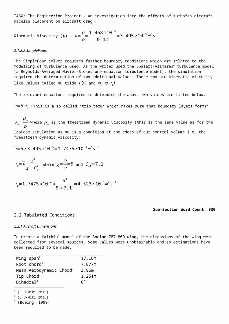
Kinematic Viscosity (ν) - ν=μρ=1.468×10
−5
0.42=3.495×10⁻⁵m2 s−1
2.1.2.2 SimpleFoam
The SimpleFoam solver requires further boundary conditions which are related to the modelling of turbulence used. As the writer used the Spalart-Allmaras4 turbulence model (a Reynolds-Averaged Navier-Stokes one-equation turbulence model), the simulation required the determination of two additional values. These two are kinematic viscosity-like values called nu tilde (~ν¿ and nu t(ν t).
The relevant equations required to determine the above two values are listed below:
3 (Public Domain Aeronautical Software, 2013)4 (CFD-Wiki,2013)
T450: The Engineering Project - An investigation into the effects of turbofan aircraft nacelle placement on aircraft drag
~ν=5ν∞ (This is a so called ‘trip term’ which makes sure that boundary layers form)5.
ν∞=μ∞
ρ where μ∞ is the freestream dynamic viscosity (this is the same value as for the IcoFoam simulation as nu is a
condition at the edges of our control volume i.e. the freestream dynamic viscosity).
~ν=5×3.495×10−5=1.7475×10⁻⁴m2 s−1
ν t=~ν χ3
χ3+Cv 13 where χ=
~νν=5 and C v 1=7.1
ν t=1.7475×10−4× 53
53+7.13=4.523×10⁻⁵m2 s−1
Sub-Section Word Count: 3302.2 Tabulated Conditions
2.2.1 Aircraft Dimensions
To create a faithful model of the Boeing 787-800 wing, the dimensions of the wing were collected from several sources. Some values were unobtainable and so estimations have been required to be made.
Wing span6 17.16mRoot chord3 7.877mMean Aerodynamic Chord3 3.96mTip Chord3 1.251mDihedral3 6˚Incidence at root (washout)3 1˚¼ chord sweep3 25.02˚Nacelle length7 3.3mAerofoil (Root Section)8 BAC449Aerofoil (Midspan Section)5 BAC450Aerofoil (Midspan Section)5 BAC451Aerofoil (Tip Section)5 BAC442Aerofoil (Nacelle)9 NACA2412
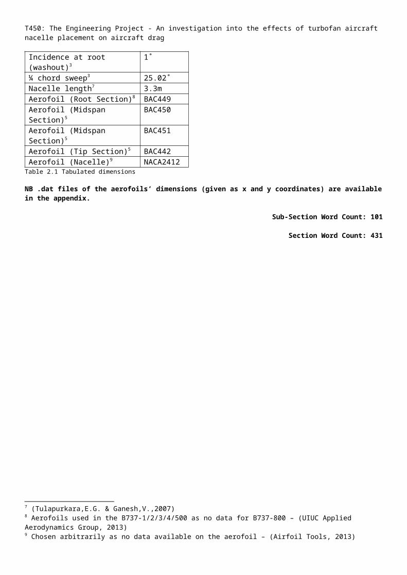
Table 2.1 Tabulated dimensions
NB .dat files of the aerofoils’ dimensions (given as x and y coordinates) are available in the appendix.
Sub-Section Word Count: 101
Section Word Count: 431
5 (CFD-Wiki,2013)6 (Boeing, 1999)7 (Tulapurkara,E.G. & Ganesh,V.,2007)8 Aerofoils used in the B737-1/2/3/4/500 as no data for B737-800 – (UIUC Applied Aerodynamics Group, 2013)9 Chosen arbitrarily as no data available on the aerofoil – (Airfoil Tools, 2013)
T450: The Engineering Project - An investigation into the effects of turbofan aircraft nacelle placement on aircraft drag
3. Determination of Drag of Simplified Wing Configurations from Calculations
3.1 Flat Plate Approximation
If we assume that the wing, nacelle and pylon act like flat plates then we can estimate the coefficient of drag (CD) to be
determined by the equationCD=
1.33√ℜ = 1.33
√ ρVLμ
.10
The total drag is then worked out by using the equationD=12ρ v2SCD
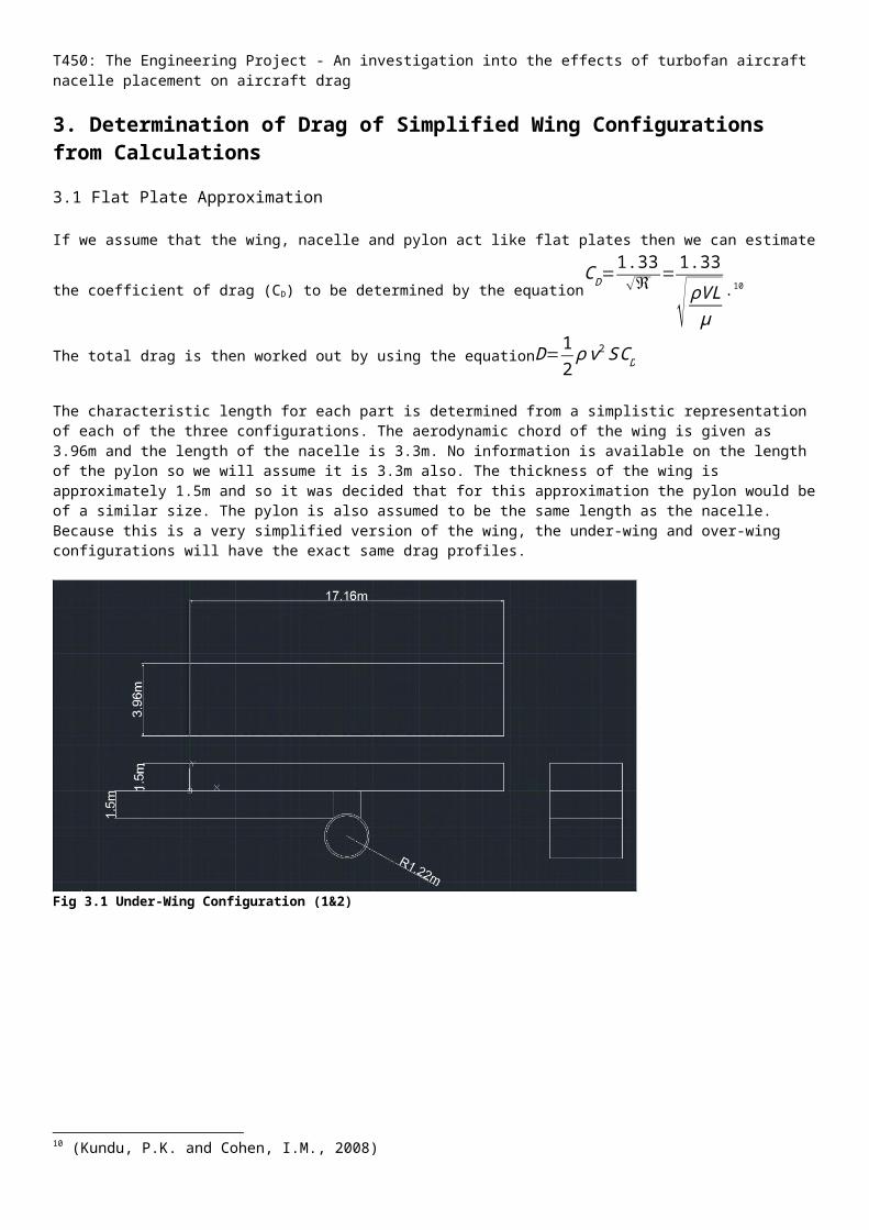
The characteristic length for each part is determined from a simplistic representation of each of the three configurations. The aerodynamic chord of the wing is given as 3.96m and the length of the nacelle is 3.3m. No information is available on the length of the pylon so we will assume it is 3.3m also. The thickness of the wing is approximately 1.5m and so it was decided that for this approximation the pylon would be of a similar size. The pylon is also assumed to be the same length as the nacelle. Because this is a very simplified version of the wing, the under-wing and over-wing configurations will have the exact same drag profiles.
Fig 3.1 Under-Wing Configuration (1&2)
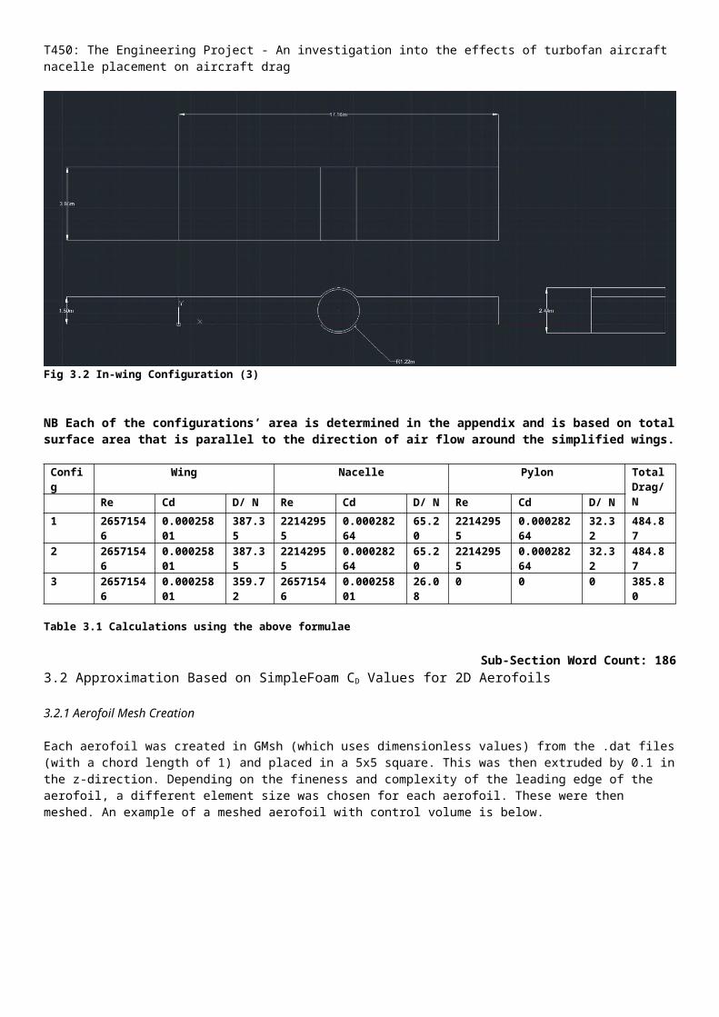
Fig 3.2 In-wing Configuration (3)
10 (Kundu, P.K. and Cohen, I.M., 2008)
T450: The Engineering Project - An investigation into the effects of turbofan aircraft nacelle placement on aircraft drag
NB Each of the configurations’ area is determined in the appendix and is based on total surface area that is parallel to the direction of air flow around the simplified wings.
Config Wing Nacelle Pylon Total Drag/ N
Re Cd D/ N Re Cd D/ N Re Cd D/ N
1 26571546
0.00025801
387.35 22142955 0.00028264
65.20 22142955 0.00028264
32.32 484.87
2 26571546
0.00025801
387.35 22142955 0.00028264
65.20 22142955 0.00028264
32.32 484.87
3 26571546
0.00025801
359.72 26571546 0.00025801
26.08 0 0 0 385.80
Table 3.1 Calculations using the above formulae
Sub-Section Word Count: 1863.2 Approximation Based on SimpleFoam CD Values for 2D Aerofoils
3.2.1 Aerofoil Mesh Creation
Each aerofoil was created in GMsh (which uses dimensionless values) from the .dat files (with a chord length of 1) and placed in a 5x5 square. This was then extruded by 0.1 in the z-direction. Depending on the fineness and complexity of the leading edge of the aerofoil, a different element size was chosen for each aerofoil. These were then meshed. An example of a meshed aerofoil with control volume is below.
Fig 3.3 Aerofoil B Mesh
3.2.2 SimpleFoam Simulation
For each aerofoil, the meshes were converted to a format that OpenFOAM could understand and surfaces changed to work for a 2D simulation in OpenFOAM. Each aerofoil was then run over 3000 iterations to provide a steady-state solution for CD values. If the simulation crashed or the values appeared not to converge, the aerofoil meshes were checked, altered and re-run. Each aerofoil’s coefficient of drag is determined by averaging the 3000 calculations of drag.
3.2.3 Approximation of Total Drag
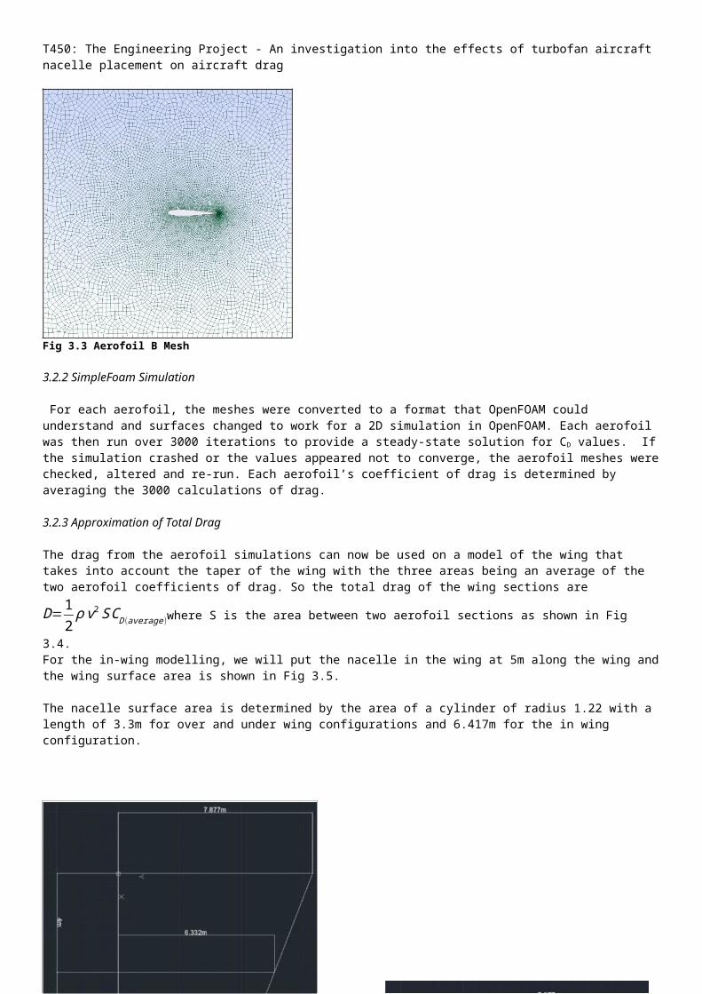
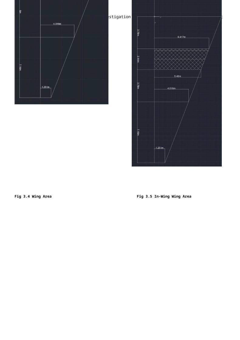
The drag from the aerofoil simulations can now be used on a model of the wing that takes into account the taper of the wing with the three areas being an average of the two aerofoil coefficients of drag. So the total drag of the wing
sections are D=12ρ v2SCD (average)where S is the area between two aerofoil sections as shown in Fig 3.4.
For the in-wing modelling, we will put the nacelle in the wing at 5m along the wing and the wing surface area is shown in Fig 3.5.
T450: The Engineering Project - An investigation into the effects of turbofan aircraft nacelle placement on aircraft drag
The nacelle surface area is determined by the area of a cylinder of radius 1.22 with a length of 3.3m for over and under wing configurations and 6.417m for the in wing configuration.
Fig 3.4 Wing Area Fig 3.5 In-Wing Wing Area
T450: The Engineering Project - An investigation into the effects of turbofan aircraft nacelle placement on aircraft drag
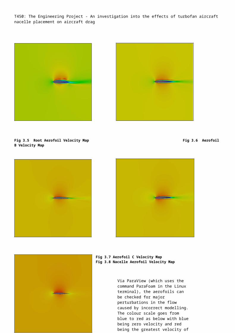
Fig 3.5 Root Aerofoil Velocity Map Fig 3.6 Aerofoil B Velocity Map
Fig 3.7 Aerofoil C Velocity Map Fig 3.8 Nacelle Aerofoil Velocity Map
Fig 3.9 Tip Aerofoil Velocity Map
Via ParaView (which uses the command ParaFoam in the Linux terminal), the aerofoils can be checked for major perturbations in the flow caused by incorrect modelling. The colour scale goes from blue to red as below with blue being zero velocity and red being the greatest velocity of the values.
Sub-Section Word Count: 268
Section Word Count: 454
T450: The Engineering Project - An investigation into the effects of turbofan aircraft nacelle placement on aircraft drag
4. Determination of Drag of Wing Configurations Using Computational Fluid Dynamics
4.1 Control Volume
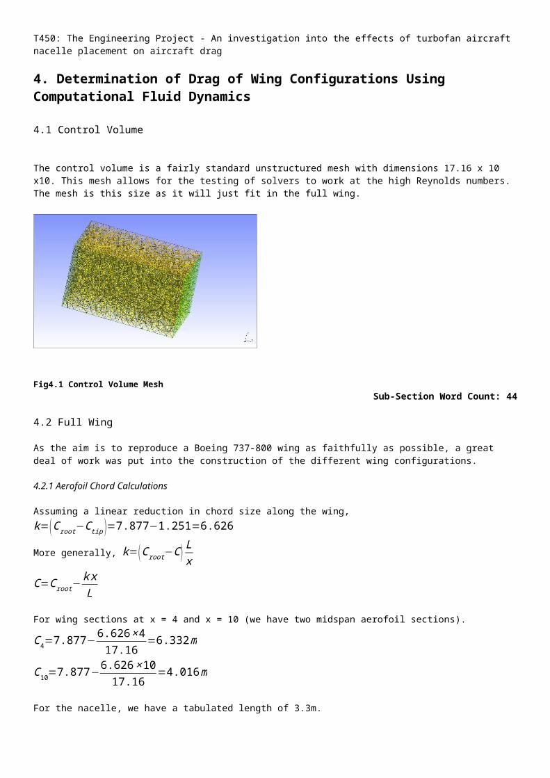
The control volume is a fairly standard unstructured mesh with dimensions 17.16 x 10 x10. This mesh allows for the testing of solvers to work at the high Reynolds numbers. The mesh is this size as it will just fit in the full wing.
Fig4.1 Control Volume MeshSub-Section Word Count: 44
4.2 Full Wing
As the aim is to reproduce a Boeing 737-800 wing as faithfully as possible, a great deal of work was put into the construction of the different wing configurations.
4.2.1 Aerofoil Chord Calculations
Assuming a linear reduction in chord size along the wing, k=(C root−C tip )=7.877−1.251=6.626
More generally, k=(C root−C ) Lx
C=C root−k xL
For wing sections at x = 4 and x = 10 (we have two midspan aerofoil sections).
C4=7.877−6.626×417.16
=6.332m
C10=7.877−6.626×1017.16
=4.016m
For the nacelle, we have a tabulated length of 3.3m.
All aerofoil .dat files only create an aerofoil with chord of 1.
If we multiply all the values in the .dat files by the chord length, we get aerofoil sections analogous to the actual aerofoils sections (which may follow the spars used to construct it).
4.2.2 Incorporating Sweep, Washout and Dihedral
Each aerofoil section then needed to be added to the overall wing at the root, four metres along, ten metres along and at the tip. As the wing is not straight, each section needed to be translated out from the origin of the wing mesh file firstly to their quarter chord point and then the final distance they needed to go i.e. aerofoil B to 4m out, aerofoil C to 10m out and tip aerofoil out to 17.16m. Each section was then moved into place on the wing by rotating firstly around the z-axis (for the dihedral transformation - 6° or 0.10472radians) and then around the y-axis (for the sweep transformation – -25.02° or -0.43668radians). This, however, misaligned the aerofoils so a reverse correction needed
T450: The Engineering Project - An investigation into the effects of turbofan aircraft nacelle placement on aircraft drag
to be made to each of the aerofoils at their quarter chord point. The root aerofoil is also given a rotation about the x-axis of 1° or 0.01745radians for the washout.
4.2.3 Adding the Nacelle
The nacelle aerofoil is added to the wing mesh file and then moved into place below the wing by 1.47 metres (this gave the nacelles approximately the same clearance as the nacelle in a Boeing 747-800). The aerofoil was then extruded by rotation to create a nacelle like volume.
4.2.4 Addition of Surfaces to Wing and Nacelle
To create the wing surface, each point on the aerofoils of the wing was attached to its adjacent aerofoil via a spline and each spline and its neighbour create the boundary for a plane surface.
4.2.5 Adding Physical Volumes and Surfaces
With all areas surfaced, GMsh requires the surfaces to be allocated as physical, otherwise it will mesh through them.
Sub-Section Word Count: 404
4.3 Solver Choices
4.3.1 IcoFoam
IcoFoam was used to orientate the author in OpenFOAM.
OpenFOAM uses a simulation folder that requires several different folders within it to work, these being ‘0’, ‘constant’ and ‘system’ and IcoFoam itself is a transient solver for inviscid fluid flows (Euler equations) at low Reynolds Numbers. This makes it unsuitable for the purposes of the simulations run. Although not used in the final simulations IcoFoam was useful.
4.3.2 SimpleFoam
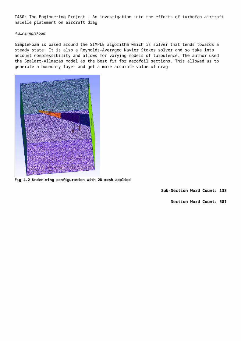
SimpleFoam is based around the SIMPLE algorithm which is solver that tends towards a steady state. It is also a Reynolds-Averaged Navier Stokes solver and so take into account compressibility and allows for varying models of turbulence. The author used the Spalart-Allmaras model as the best fit for aerofoil sections. This allowed us to generate a boundary layer and get a more accurate value of drag.
Fig 4.2 Under-wing configuration with 2D mesh applied
Sub-Section Word Count: 133
T450: The Engineering Project - An investigation into the effects of turbofan aircraft nacelle placement on aircraft drag
Section Word Count: 581
T450: The Engineering Project - An investigation into the effects of turbofan aircraft nacelle placement on aircraft drag
5. Analysis and Findings
5.1 Flat Plate Approximation
As we can see from section 3.1, the values of drag for over-wing, under-wing and in-wing configurations are as follows:
Over-wing – 484.87NUnder-wing – 484.87NIn-wing – 385.80N
Whilst this shows a definitive difference, the flat plate approximation model is flawed in that it only accounts for skin friction only and does not take into account any aerodynamic drag effects caused by a boundary layer and turbulent flow around the wing.
Sub-Section Word Count: 69
5.2 2D Aerofoil Drag
With the 2D aerofoils, the values of drag for over-wing, under-wing and in-wing configurations are as follows:
Over-wing – 64.837kNUnder-wing – 64.837kNIn-wing – 99.939kN
As we can see, the increased area of an in-wing nacelle seems to have turned the tables towards over and under wing configurations. This may be due to the high coefficient of drag of the nacelle aerofoil.
Sub-Section Word Count: 60
5.3 Full Wing
The hope of the author was to investigate the interactions of fluid flow around the nacelle and wing to see if one of the configurations would come out with the most favourable drag profile. Unfortunately, with the time constraints placed on the project, the author didn’t manage to complete this. An accumulation of learning new applications, new operating system and the concepts behind Computational Fluid Dynamics made it very difficult to provide workable meshes within the time limit.
Sub-Section Word Count: 78
5.4 Points of Continuation
A further project could explore a completion of the wing simulations to provide a definitive answer to which wing configuration provides the best drag profile overall. It may be that a more complex solver is required as well as a greater knowledge of some of the aircraft’s dimensions.
Sub-Section Word Count: 48
5.4 Conclusion
Unfortunately, there was not enough time to get a definitive answer on which wing configuration was the most efficient from a drag point of view. With more time, all three of the wing configurations could have been tested fully to give us a better answer.
Sub-Section Word Count: 45Section Word Count: 300

T450: The Engineering Project - An investigation into the effects of turbofan aircraft nacelle placement on aircraft drag
6. Further Analysis – How to Expand on This Project
6.1 Structural Analysis
6.1.1 The Wing as a Whole
A structural analysis of the wing with nacelle could provide insight into nacelle placement by measuring the static stress via models such as a standard beam analysis or more complex models using finite element analysis of the wing.
6.1.2 Ground-Air-Ground (GAG) Cycle Modelling
Another part of the analysis could be determining how the ground-air-ground cycle of the aircraft is affected by different configurations with a standard sized crack in the wing.
6.1.3 Nacelle Pylons
As the main component transmitting the thrust of the engines to the rest of the airframe, this section may need an analysis of its own to see how the moving of the nacelle will affect geometry and material choices for the pylon.
Sub-Section Word Count: 1226.2 Systems Analysis
From systems diagrams and discussions with other engineers, a list of other issues that may need to be considered in the placement of passenger aircraft nacelles was developed. These are listed below with some ideas on how to progress with them.
6.2.1 Runway Debris
An analysis of the change in runway debris entering the engines could provide some interesting insights into how engine placement could improve the lifespan of the aircraft’s compressor blades.
6.2.2 Stability Issues
Altering the placement of an aircraft’s nacelles will probably alter the centre of mass, thrust and lift. This will in turn have an effect on the aircraft’s stability.
6.2.3 Bird Strikes
Although bird strikes are relatively infrequent and rarely cause damage to the engines, it may be worth investigating whether nacelle placement would reduce the probability of a bird strike causing engine damage or indeed pylon damage.
6.2.4 Turbine Disc Burst Damage
If a turbine disk fails under load, it has a tendency to break into three sections, which are then flung out of the engine at high speed. Nacelle placement may increase or decrease the probability of a piece of burst turbine disc from impacting with a critical system. Would a particular placement still provide more benefits from other factors to make it worth baffling the engine more to reduce an unfavourable result of a turbine disc burst?
6.2.5 Design Alteration Costs
Would any of the nacelle placements require the turbofan manufacturers to redesign their current offerings to support a new placement? Are there standard attachment points machined into the outside that could make alteration difficult?
Would the use of an in-wing engine mean that an aircraft would require a longer wing to provide the same lift? All of these factors contribute to a need to alter tried and tested airframes and come at a cost. This would be an interesting analysis to explore whether the benefits would outweigh the original outlay on more research and development.
T450: The Engineering Project - An investigation into the effects of turbofan aircraft nacelle placement on aircraft drag
6.2.6 Maintenance Inspection
Something as simple as ease of inspection may have an effect on whether airlines will purchase aircraft; after all, their staff are the ones who will have to make inspections regularly, throughout the day, on their fleet of aircraft.
6.2.7 Vibration Transmission
During the life of a turbofan engine, there will be some vibrations when in service. The placement of aircraft nacelles may have an effect on how these are transmitted to the rest of the airframe and this could be another consideration for analysis.
Sub-Section Word Count: 415
6.3 Computational Aeroacoustics (CAA) Modelling
In a similar vein to this project, the modelling of a wing could be used to determine how much aircraft noise reaches the ground during take-off. Modelling of the turbofan noise could either be taken from experiment (the turbofans will tend to be at 100% thrust at this point in the flight) or determined from (Polacsek, C. et al, 2009) should such information be not freely available. Unlike this project, the fuselage of the aircraft would need to be included so that any reflection of engine noise is included in a ‘sound map’ below the aircraft.
Sub-Section Word Count: 96Section Word Count: 633
Summary: 145Section 1: 1433Section 2: 431Section 3: 454Section 4:581Section 5:300
Section 6: 633Total Word Count: 3977
T450: The Engineering Project - An investigation into the effects of turbofan aircraft nacelle placement on aircraft drag
References
Websites
Bombardier (2013) Learjet [Online]. Available at http://businessaircraft.bombardier.com/en/aircraft/learjet.html (Accessed 3rd March 2013)
Gulfstream (2013) G150 Overview – Gulfstream [Online]. Available at http://www.gulfstream.com/products/g150/ (Accessed 3rd March 2013)
Boeing Commercial (2013) 737-800 Technical Information [Online]. Available at http://www.boeing.com/commercial/737family/pf/pf_800tech.html (Accessed on 14th March 2013)
Committee on Climate Change (2013) Demand for Air Travel [Online]. Available at http://www.theccc.org.uk/sectors/aviation/demand-for-air-travel (Accessed 3rd March 2013).
Committee on Climate Change (2013) Aviation Factsheet [Online]. Available at http://www.theccc.org.uk/publication/aviation-factsheet/ (Accessed 24th August 2013).
Heathrow Association for the Control of Aircraft Noise Clear Skies (2006) HACAN Clear Skies [Online]. Available at http://www.hacan.org.uk/ (Accessed 3rd March 2013).
UIUC Applied Aerodynamics Group (2013) UIUC Airfoil Data Site [Online]. Available at http://www.ae.illinois.edu/m-selig/ads/coord_database.html (Accessed 5th March 2013).
Airfoil Tools (2013) NACA 4 digit airfoil generator (NACA 2412 AIRFOIL) [Online]. Available at http://airfoiltools.com/airfoiltools/airfoil/naca4digit?MNaca4DigitForm%5Bcamber%5D=2&MNaca4DigitForm%5Bposition%5D=40&MNaca4DigitForm%5Bthick%5D=12&MNaca4DigitForm%5BnumPoints%5D=46&MNaca4DigitForm%5BcosSpace%5D=0&MNaca4DigitForm%5BcosSpace%5D=1&MNaca4DigitForm%5BcloseTe%5D=0&MNaca4DigitForm%5BcloseTe%5D=1&yt0=Plot (Accessed 8th June 2013).
CFD Online (2008) Spalart-Allmaras model – CFD-Wiki, the free CFD reference [Online]. Available at http://www.cfd-online.com/Wiki/Spalart-Allmaras_model (Accessed 15th June 2013).
CFD Online (2008) Turbulence free-stream boundary conditions – CFD-Wiki, the free CFD reference [Online]. Available at http://www.cfd-online.com/Wiki/Turbulence_free-stream_boundary_conditions (Accessed 15th June 2013).
Public Domain Aeronautic Software (2013) A Table of Standard Atmosphere to 86km [Online]. Available at http://www.pdas.com/m1.html (Accessed 25th May 2013).
The 737 Information Site (1999) The Boeing 737 Technical Site [Online]. Available at http://www.b737.org.uk/flightcontrols.htm (Accessed 9th April 2013).
NTNU HPC Group (2013) OpenFOAM – Airfoil Calculations – HPC Wiki – Confluence [Online]. Available at https://www.hpc.ntnu.no/display/hpc/OpenFOAM+-+Airfoil+Calculations (Accessed 20th June 2013).
OpenFOAM Wiki (2013) 2D Mesh Tutorial using GMSH – OpenFOAM Wiki [Online]. Available at http://openfoamwiki.net/index.php/2D_Mesh_Tutorial_using_GMSH (Accessed 18th June 2013).
Canonical Ltd. (2013) Ubuntu Engineering – Community Ubuntu Documentation [Online]. Available at https://help.ubuntu.com/community/UbuntuEngineering (Accessed 19th March 2013).
Podcasts
Williams, M. (2012) ‘One Planet: Airlines United Against Europe’ BBC World Service [Podcast] 13th January. Available at http://www.bbc.co.uk/iplayer/episode/p00msxhj/One_Planet_Archive_Airlines_united_against_Europe/ (Accessed 14th January 2012)
T450: The Engineering Project - An investigation into the effects of turbofan aircraft nacelle placement on aircraft drag
Software
OpenCFD Ltd (ESI Group) (2013) OpenFOAM –The Open Source CFD Toolbox (Version 2.2.0) [Computer Program] Available at http://www.openfoam.com/ (Accessed 11th February 2013).
Geuzaine, C.and Remacle, JF (2013) GMsh (Version 2.8.2) [Computer Program] Available at http://geuz.org/gmsh/ (Accessed 20th March 2013).
Canonical Ltd. (2013) Ubuntu (Version 12.10) [Computer Program] Available at http://www.ubuntu.com/desktop (Accessed 9th February 2013).
Autodesk (2013) Autocad 2014 (Version 1.18.0.0) [Computer Program] Available at http://www.autodesk.co.uk/products/autodesk-autocad/overview (Accessed 1st August 2013)
E-Journal Articles
Korte, D., Hüttl, T., Kennepol, F. and Heinig, K. (2005) ‘Numerical simulation of multistage turbine sound generation and propagation’ Aerospace Science and Technology vol. 9, no. 2 [Online] Available at http://www.sciencedirect.com/science/article/pii/S1270963805000027# (Accessed 5th March 2013)
Polacsek, C., Desquesnes, G. and Reboul, G. (2009) ‘An equivalent-source model for simulating noise generation in turbofan engines’ Journal of Sound and Vibration vol. 323, no. 3-5 [Online] Available at http://www.sciencedirect.com.libezproxy.open.ac.uk/science/article/pii/S0022460X09000224 (Accessed 5th March 2013)
Sasaki, D. and Nakahashi, K. (2011) 'Aerodynamic Optimization of an Over-the-Wing-Nacelle-Mount Configuration', Modeling & Simulation in Engineering, vol. 2011 [Online] Available at http://libezproxy.open.ac.uk/login?url=http://search.ebscohost.com/login.aspx?direct=true&db=a9h&AN=70967794&site=eds-live&scope=site (Accessed 10th March 2013)
Destarac, D. and Van, D.V. (2004) ‘Drag/thrust analysis of jet-propelled transonic transport aircraft; Definition of physical drag components’ Aerospace Science and Technology , vol. 8, no.6 [Online] Available at http://www.sciencedirect.com.libezproxy.open.ac.uk/science/article/pii/S1270963804000343 (Accessed 23rd April 2013)
Trapp, L.G. and Argentieri, H.G. (2010) 'Evaluation of nacelle drag using Computational Fluid Dynamics', Journal of Aerospace Technology and Management, vol. 2, no. 2 [Online] Available at http://www.jatm.com.br/papers/vol2_n2/JATMv2n2_p145-153_Evaluation_of_nacelle_drag_using_Computational_Fluid_Dynamics.pdf (Accessed 23rd April 2013)
Online Documents
OpenFOAM CFD Ltd (ESI Group) (2012) OpenFOAM - The Open Source CFD Toolbox User Guide [Online] Available at http://www.openfoam.org/docs/ (Accessed 11th February 2013)
Tulapurkara, E.G. and Ganesh, V. (2009) Performance estimation of a typical subsonic jet transport airplane [Online] National Programme on Technology Enhanced Learning. Available at http://nptel.iitm.ac.in/courses/101106041/Appendix-B%20Lecture%2038%2022-12-2011.pdf (Accessed 23rd April 2013)
Abedi, H. (2011) A SimpleFoam tutorial [Online], Chalmers University of Technology. Available at http://www.tfd.chalmers.se/~hani/kurser/OS_CFD_2011/HamidrezaAbedi/report_task_3.pdf (Accessed 15th June)
Kuzmin, D. (2013) Introduction to Computational Fluid Dynamics [Online] Technische Universität Dortmund. Avaiable at http://www.mathematik.uni-dortmund.de/~kuzmin/cfdintro/lecture1.pdf (Accessed 20th April 2013)
T450: The Engineering Project - An investigation into the effects of turbofan aircraft nacelle placement on aircraft drag
Books
Kundu, P.K. and Cohen, I.M. (2008) Fluid Mechanics, 4th edn. United States of America, Academic Press.
Anderson, J.D (1995) Computational Fluid Dynamics: The Basics with Applications, 3rd edn. New Delhi, Tata McGraw Hill.
Phone Conversations
Odie,K (2013) Telephone Conversation with Phil Brown, 26th February 2013
Open University Material
The Open University (2009) MST326 Unit 1: Mathematical methods and fluid mechanics, Milton Keynes, The Open University
YouTube Video
How to Dual Boot A PC With Windows 7 & Ubuntu 10.10 Maverick Meerkat (2011) YouTube video, added by TechHarvest [Online]. Available at http://www.youtube.com/watch?v=FmN4Pj3VWpc. (Accessed 11th February 2013).

T450: The Engineering Project - An investigation into the effects of turbofan aircraft nacelle placement on aircraft drag
AppendixProposal
Proposal - https://www.dropbox.com/s/lpco09q3x7dohlq/Project%20Aim.docTutor Feedback – https://www.dropbox.com/s/a17cwbr1qp8bl25/Philip%20Brown%20Project%20Aim.docExternal Examiner Feedback - https://www.dropbox.com/s/t5ie435iv3rcnzv/Y3292943%20Brown.doc
Flat-Plate Approximation Calculations
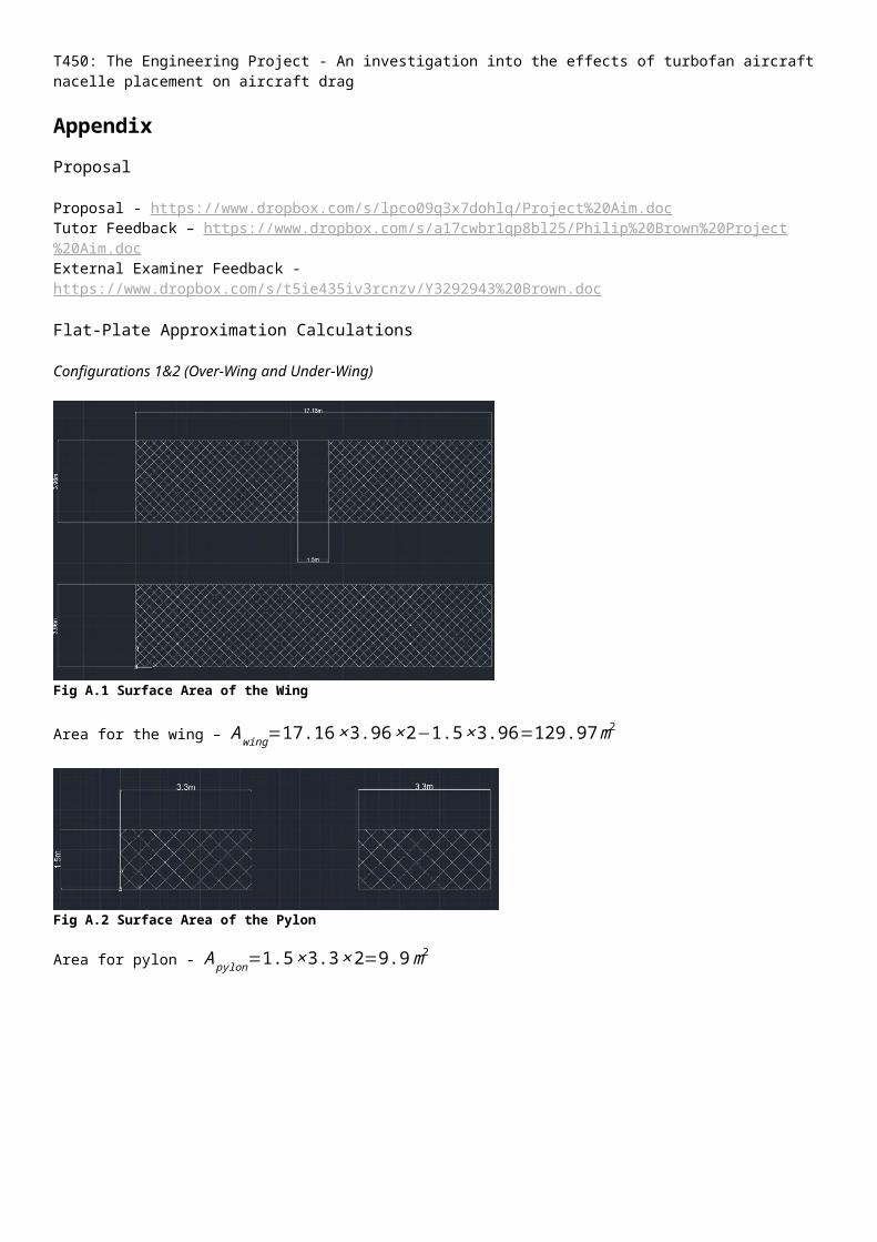
Configurations 1&2 (Over-Wing and Under-Wing)
Fig A.1 Surface Area of the Wing
Area for the wing – Awing=17.16×3.96×2−1.5×3.96=129.97m2
Fig A.2 Surface Area of the Pylon
Area for pylon - Apylon=1.5×3.3×2=9.9m2
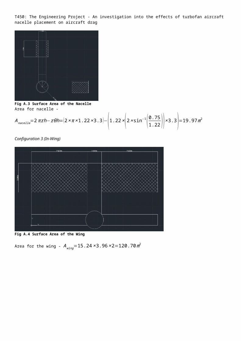
Fig A.3 Surface Area of the Nacelle
T450: The Engineering Project - An investigation into the effects of turbofan aircraft nacelle placement on aircraft drag
Area for nacelle - Anacelle=2πrh−rθh=(2×π×1.22×3.3 )−(1.22×(2× sin−1( 0.751.22 ))×3.3)=19.97m2
Configuration 3 (In-Wing)
Fig A.4 Surface Area of the Wing
Area for the wing - Awing=15.24×3.96×2=120.70m2
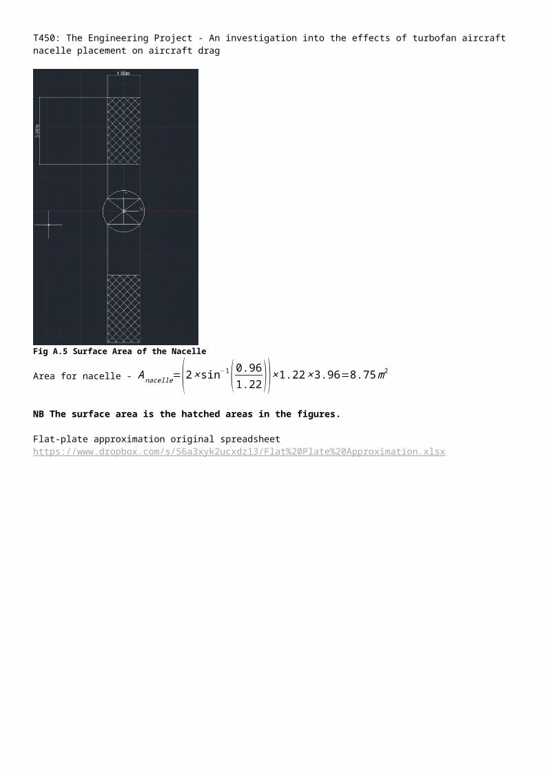
Fig A.5 Surface Area of the Nacelle
Area for nacelle - Anacelle=(2×sin−1( 0.961.22 ))×1.22×3.96=8.75m2
NB The surface area is the hatched areas in the figures.
T450: The Engineering Project - An investigation into the effects of turbofan aircraft nacelle placement on aircraft drag
Flat-plate approximation original spreadsheet https://www.dropbox.com/s/56a3xyk2ucxdz13/Flat%20Plate%20Approximation.xlsx
T450: The Engineering Project - An investigation into the effects of turbofan aircraft nacelle placement on aircraft drag
2D Aerofoil
2D Aerofoil Meshes
These can be viewed using GMsh Open Source Meshing Program
Root Geo and Mesh Fileshttps://www.dropbox.com/s/pzz55thetet0l69/rootmesh.geo https://www.dropbox.com/s/tlgyfltrgo5q780/rootmesh.msh Aerofoil B Geo and Mesh Fileshttps://www.dropbox.com/s/b8wqgdxin2qpnol/Bmesh.geohttps://www.dropbox.com/s/va26195hwtznv80/Bmesh.msh
Aerofoil C Geo and Mesh Fileshttps://www.dropbox.com/s/ffby6e3baznpdlr/Cmesh.geohttps://www.dropbox.com/s/6obxhybzcygjx5x/Cmesh.msh Tip Geo and Mesh Fileshttps://www.dropbox.com/s/w26u9c74oz0njoy/tipmesh.geohttps://www.dropbox.com/s/b9biivjhd2lj1z9/tipmesh.msh
Nacelle Geo and Mesh Fileshttps://www.dropbox.com/s/lqqu90qbm6wjgq1/nacellefoil.geohttps://www.dropbox.com/s/n8i2z3s0g9hee7s/nacellefoil.msh
2D Simulation Files
These can be viewed using OpenFOAM’s ParaFoam software.
Root Simulation Folderhttps://www.dropbox.com/sh/h1uioy4i151met7/gWkbrUZlDA (57.7MB)
Aerofoil B Simulation Folderhttps://www.dropbox.com/sh/ze5y2z8fquskrcs/DCkbdMoee0 (56.1MB)
Aerofoil C Simulation Folderhttps://www.dropbox.com/sh/ayuaczj5b4evu4v/7AFPX7Hvu7 (80.3MB)
Tip Simulation Folderhttps://www.dropbox.com/sh/xbf5uyhkc0kwgky/4gPlfmD15r (136MB)
Nacelle Simulation Folderhttps://www.dropbox.com/sh/3umq5gurtyuw5jr/yhq34xViLf (20.6MB)
Area Calculations
Over-Wing and Under-Wing
Area between Root Aerofoil and Aerofoil B
S1=C 4×x+ 12x× (Croot−C4 )=6.332×4+ 12 4× (7.877−6.332 )=29.191m2
Area between Aerofoil B and C
S2=C 10× x+ 12x × (C4−C10 )=4.016×6+ 12 6× (6.332−4.016 )=31.044m2
Area between Aerofoil C and Tip Aerofoil
S3=C tip×x+ 12x× (C10−C tip )=1.251×7.16+ 12 7.16× (4.016−1.251 )=18.849m2
Area of Nacelle
T450: The Engineering Project - An investigation into the effects of turbofan aircraft nacelle placement on aircraft drag
S4=π r2l=π ×1.222×3.3=15.431m2
In-wing
Area between Root Aerofoil and Aerofoil B
S1=C 4×x+ 12x× (Croot−C4 )=6.417×3.78+ 12×3.78× (7.877−6.417 )=27.016m2
Area between Aerofoil B and C
S2=C10× x+ 12x × (C4−C10 )=4.016×3.78+ 12×3.78× (5.48−4.016 )=17.947m2
Area between Aerofoil C and Tip Aerofoil
S3=C tip×x+ 12x× (C10−C tip )=1.251×7.16+ 12 7.16× (4.016−1.251 )=18.849m2
Area of NacelleS4=π r2l=π ×1.222×6.417=30.006m2
Coefficient of Drag Spreadsheets
Root Aerofoil – https://www.dropbox.com/s/bw9r8sywx5p3kda/Root%20Aerofoil%20Cd%20Values.xls Aerofoil B – https://www.dropbox.com/s/vahaw4fu9ligtua/Aerofoil%20B%20Cd%20Values.xls Aerofoil C – https://www.dropbox.com/s/h929hrzpwil1mef/Aerofoil%20C%20Cd%20Values.xls Tip Aerofoil - https://www.dropbox.com/s/546j9juisr5csuo/Tip%20Aerofoil%20Cd%20Values.xls Nacelle Aerofoil - https://www.dropbox.com/s/d84ijqe0mk5sspe/Nacelle%20Cd%20Values.xls
Average Coefficients of Drag
Between Root and Aerofoil B - Cd (root )+Cd (B )
2=0.01816+0.03227
2=0.02521
Between Aerofoil B and C - Cd (B )+Cd (C )
2= 0.03227+0.01232
2=0.02230
Between Aerofoil C and Tip - Cd (C )+Cd (Tip )
2=0.01232+0.05138
2=0.03185
Nacelle – 0.2323
Drag of Sections (Over-Wing and Under-Wing)
D1=12ρv2S1CD=
12×0.42×234.532×29.191×0.02521=8500.4N
D2=12ρv2S2C D=
12×0.42×234.532×31.044×0.02230=7996.5N
D3=12ρ v2S3CD=
12×0.42×234.532×18.849×0.03185=6934.5N
D4=12ρ v2S4CD=
12×0.42×234.532×15.431×0.2323=41405.6 N
Total Drag=8500.4+7996.5+6934.5+41405.6=64837.0N=64.837 kN
Drag of Sections (In-Wing)
D1=12ρv2S1CD=
12×0.42×234.532×27.016×0.02521=7867.0N
T450: The Engineering Project - An investigation into the effects of turbofan aircraft nacelle placement on aircraft drag
D2=12ρv2S2C D=
12×0.42×234.532×17.947×0.02230=4622.9N
D3=12ρ v2S3CD=
12×0.42×234.532×18.849×0.03185=6934.5N
D4=12ρ v2S4CD=
12×0.42×234.532×30.006×0.2323=80514.4N
Total Drag=7867.0+4622.9+6934.5+80514.4=99938.8N=99.939 kN

T450: The Engineering Project - An investigation into the effects of turbofan aircraft nacelle placement on aircraft drag
Mesh Development
Aerofoil Chord Calculations
Modified .dat files (can be viewed using notepad)
Root aerofoil - https://www.dropbox.com/s/13rlvf9rzjo3m3r/b737a%28corrected%29.datMid span aerofoil - https://www.dropbox.com/s/tfs20k009xoqq1d/b737b%28corrected%29.datMid span aerofoil - https://www.dropbox.com/s/x7bxqzc3e2j76d7/b737c%28corrected%29.datTip aerofoil - https://www.dropbox.com/s/iinuqvi3ibhqffm/b737d%20%28corrected%29.datNacelle aerofoil (in-wing) - https://www.dropbox.com/s/vrv7ijhlk6epy6r/NACA2412%28inwing%29.datNacelle aerofoil (under/over-wing) - https://www.dropbox.com/s/lf6r7gdfh1meft5/NACA2412%28underwing%29.dat
Introducing Sweep, Washout and Dihedral
Transformation calculations for determining quarter chord position of aerofoils (viewable with Excel) https://www.dropbox.com/s/hnse9izpvth5aip/transformations%20for%20rotating%20aerofoils.ods
Attempted Mesh File
Wing2.geo (only able to get the wing to mesh inside the control volume) https://www.dropbox.com/s/y3cmxl7j1e2zeb6/wing2.geo
Wing 2.msh (viewable using Gmsh) https://www.dropbox.com/s/o5ki6dix4sbqbl7/wing2.msh
Test Simulation
The test simulation is approximately 100MB and therefore left out of the appendix. If you would like a copy of the file, please contact me at [email protected] .
T450: The Engineering Project - An investigation into the effects of turbofan aircraft nacelle placement on aircraft drag
Further Analysis
Systems Analysis
A.6 Spray Diagram of points of continuation
Nacelle Placement
CAA
Take-Off
Include fuselage
(Polacsek,C et al., 2009)
‘Sound Map’
Financial
Design Alteration Cost
Maintenance Inspection
Structural
The Wing as a Whole
Ground-Air-Ground Cycle
Modelling
Nacelle Pylons
Safety
Runway Debris
Bird Strikes
Turbine Disc Burst Damage
Stability Issues
Comfort
Vibration Transmission
T450: The Engineering Project - An investigation into the effects of turbofan aircraft nacelle placement on aircraft drag
Glossary
Nomenclature
Atmosphere
Symbol Description Unitsρ Density of air kgm-3
p Pressure Pap0 Pressure at sea level Paθz Temperature at altitude z Kθ0 Temperature at sea level Kg Acceleration due to gravity ms-2
R Universal gas constant Jmol-1K-1
k Rate of temperature drop per metre Km-1
cair Speed of sound in air ms-1
γ Heat capacity ratiov Velocity of the aircraft ms-1
M Aircraft speed (Mach)µ Dynamic viscosity kgm-1s-1
ν Kinematic viscosity m2s-1
Simulations
Symbol Description Units~ν Kinematic viscosity-like value m2s-1
ν t Kinematic viscosity-like value m2s-1
ν∞ Freestream kinematic viscosity m2s-1
µ∞ Freestream dynamic viscosity kgm-1s-1
Flat-Plate Approximation Calculations
Symbol Description Unitsρ Density of air kgm-3
v Velocity of the aircraft ms-1
S Area of the surface m2
CD Coefficient of dragRe Reynolds numberL Characteristic length mD Drag force Nµ Dynamic viscosity kgm-1s-1
Awing Area of wing m2
Anacelle Area of nacelle m2
Apylon Area of pylon m2
2D Aerofoil
Symbol Description UnitsA1 Area between root and aerofoil b m2
A2 Area between aerofoil b and aerofoil c m2
A3 Area between aerofoil c and tip m2
A4 Area of nacelle m2
Ctip Chord length at tip mCroot Chord length at root mC4 Chord length at x=4 mC10 Chord length at x=10 mx Length of wing section m
T450: The Engineering Project - An investigation into the effects of turbofan aircraft nacelle placement on aircraft drag
r Radius of nacelle ml Length of nacelle mD1 Drag of Area 1 ND2 Drag of Area 2 ND3 Drag of Area 3 ND4 Drag of Nacelle N
Mesh Development
Symbol Description Unitsk TaperingL Wing length mC Chord length mx Distance along the wing mCtip Chord length at tip mCroot Chord length at root mC4 Chord length at x=4 mC10 Chord length at x=10 m