doc.: IEEE 802.15-07-0934-01-003c Submission Slide 1 November, 2007 Various Authors, TG3c Proposal Project: IEEE P802.15 Working Group for Wireless Personal Area Networks (WPANs) Submission Title: [Merged proposal: New PHY Layer and Enhancement of MAC for mmWave System Proposal] Date Submitted: [November 13, 2007] Source: [Hiroshi Harada (1) , Ismail Lakkis (2) (representative contributors), other contributors are listed in “Contributors” slides] Company [National Institute of Information and Communications Technology (NICT), Tensorcom Inc., and other contributors are listed in “Contributors” slides ] Address 1 [3-4 Hikari-no-oka, Yokosuka-shi, Kanagawa 239-0847, Japan] Voice 1 :[+81-46-847-5074] , FAX 1 : [+81-46-847-5440] Address 2 [10875, Rancho Bernardo Rd #108, San Diego, CA, USA] Voice 2 :[858-231-9753], FAX 2 : [858-676-0300] E-Mail:[[email protected], [email protected] (other contributors are listed in “Contributors” slides)] Re: [In response to TG3c Call for Proposals (IEEE P802.15-07-0586-02-003c)] Abstract: [Merged proposal of new PHY layer and enhancement of MAC for mmWave system proposal] Purpose: [To be considered in TG3C baseline document.] Notice: This document has been prepared to assist the IEEE P802.15. It is offered as a basis for discussion and is not binding on the contributing individual(s) or organization(s). The material in this document is subject to change in form and content after further study. The contributor(s) reserve(s) the right to add, amend or withdraw material contained herein. Release: The contributors acknowledge and accept that this contribution becomes the property of IEEE and may be made publicly available by P802.15.
Transcript
doc.: IEEE 802.15-07-0934-01-003c
Submission Slide 1
November, 2007
Various Authors, TG3c Proposal
Project: IEEE P802.15 Working Group for Wireless Personal Area Networks (WPANs)
Submission Title: [Merged proposal: New PHY Layer and Enhancement of MAC for mmWave System
Proposal]
Date Submitted: [November 13, 2007]
Source: [Hiroshi Harada(1), Ismail Lakkis(2) (representative contributors), other contributors are listed in
“Contributors” slides]
Company [National Institute of Information and Communications Technology (NICT), Tensorcom Inc.,
and other contributors are listed in “Contributors” slides ]
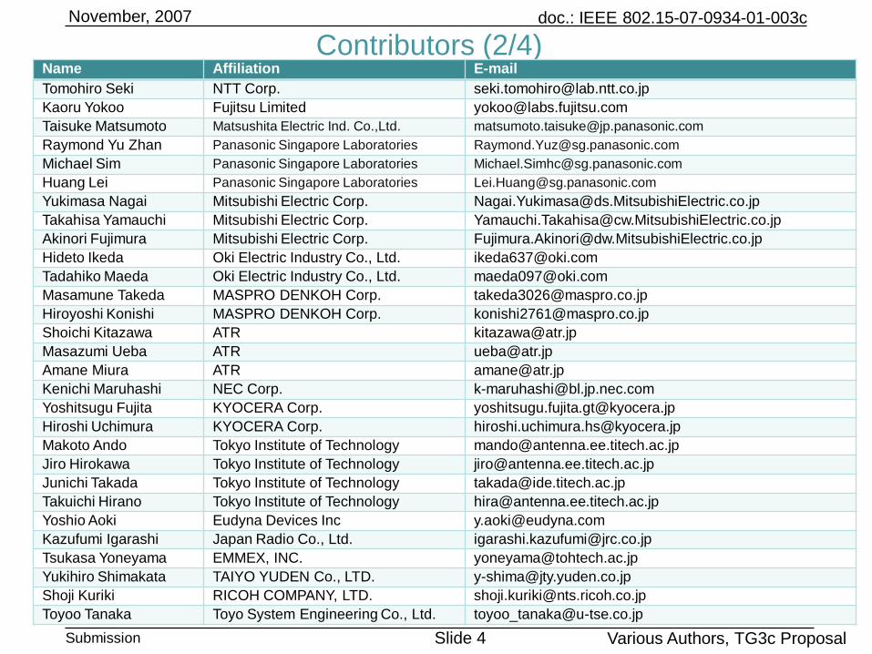
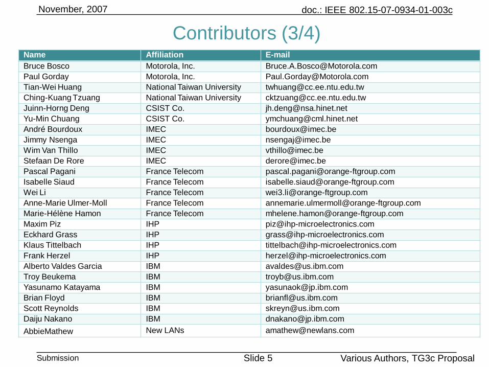
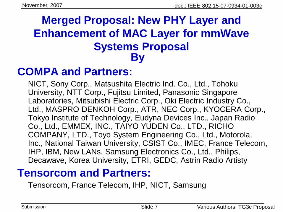
COMPA and Partners:NICT, Sony Corp., Matsushita Electric Ind. Co., Ltd., Tohoku University, NTT Corp., Fujitsu Limited, Panasonic Singapore Laboratories, Mitsubishi Electric Corp., Oki Electric Industry Co., Ltd., MASPRO DENKOH Corp., ATR, NEC Corp., KYOCERA Corp., Tokyo Institute of Technology, Eudyna Devices Inc., Japan Radio Co., Ltd., EMMEX, INC., TAIYO YUDEN Co., LTD., RICHO COMPANY, LTD., Toyo System Engineering Co., Ltd., Motorola, Inc., National Taiwan University, CSIST Co., IMEC, France Telecom, IHP, IBM, New LANs, Samsung Electronics Co., Ltd., Philips, Decawave, Korea University, ETRI, GEDC, Astrin Radio Artisty
Tensorcom and Partners: Tensorcom, France Telecom, IHP, NICT, Samsung
doc.: IEEE 802.15-07-0934-01-003c
Submission Slide 8
November, 2007
Various Authors, TG3c Proposal
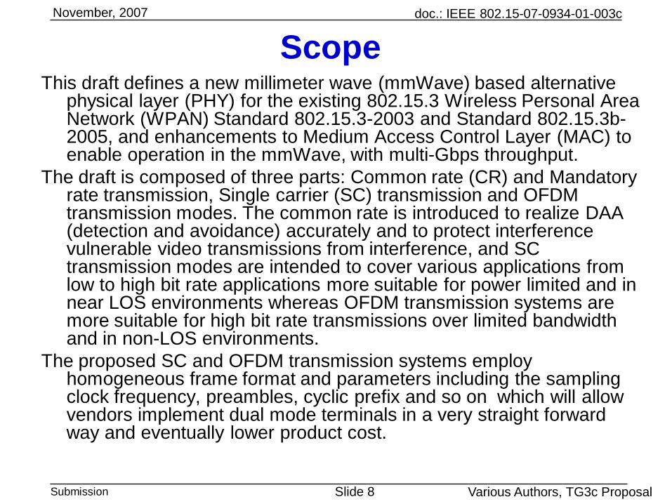
ScopeThis draft defines a new millimeter wave (mmWave) based alternative
physical layer (PHY) for the existing 802.15.3 Wireless Personal Area Network (WPAN) Standard 802.15.3-2003 and Standard 802.15.3b-2005, and enhancements to Medium Access Control Layer (MAC) to enable operation in the mmWave, with multi-Gbps throughput.
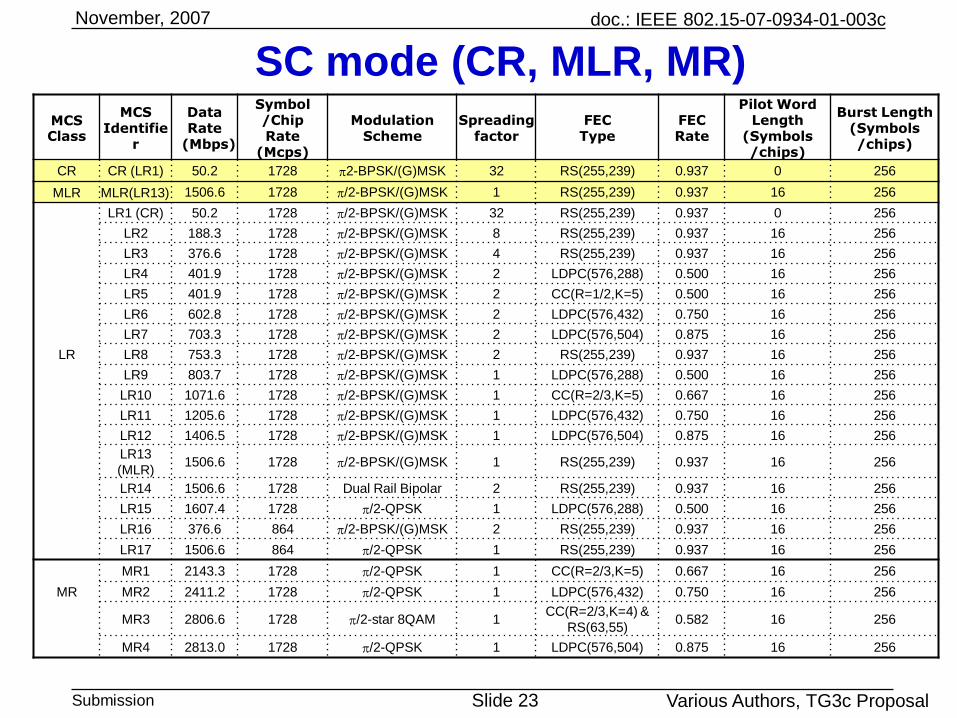
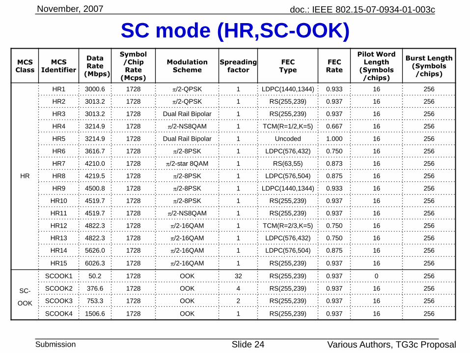
The draft is composed of three parts: Common rate (CR) and Mandatory rate transmission, Single carrier (SC) transmission and OFDM transmission modes. The common rate is introduced to realize DAA (detection and avoidance) accurately and to protect interference vulnerable video transmissions from interference, and SC transmission modes are intended to cover various applications from low to high bit rate applications more suitable for power limited and in near LOS environments whereas OFDM transmission systems are more suitable for high bit rate transmissions over limited bandwidth and in non-LOS environments.
The proposed SC and OFDM transmission systems employ homogeneous frame format and parameters including the sampling clock frequency, preambles, cyclic prefix and so on which will allow vendors implement dual mode terminals in a very straight forward way and eventually lower product cost.
doc.: IEEE 802.15-07-0934-01-003c
Submission Slide 9
November, 2007
Various Authors, TG3c Proposal
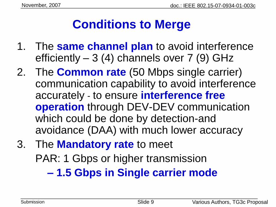
Conditions to Merge
1. The same channel plan to avoid interference efficiently – 3 (4) channels over 7 (9) GHz
2. The Common rate (50 Mbps single carrier) communication capability to avoid interference accurately - to ensure interference free operation through DEV-DEV communication which could be done by detection-and avoidance (DAA) with much lower accuracy
3. The Mandatory rate to meet
PAR: 1 Gbps or higher transmission
– 1.5 Gbps in Single carrier mode
doc.: IEEE 802.15-07-0934-01-003c
Submission Slide 10
November, 2007
Various Authors, TG3c Proposal
1. Same Channel plan: full-rate (2GHz)
Ch
#A1
Ch
#A2
Ch
#A4
240
MHz
120
MHz
1728 MHz
2160 MHz
Ch
#A3
57 58 59 60 61 62 63 64 65 66 fGHz
Channel
Number
Low Freq.
(GHz)
Center Freq.
(GHz)
High Freq.
(GHz)
Nyquist BW
(MHz)
Roll-Off
Factor
A1 57.240 58.320 59.400 1728 0.25
A2 59.400 60.480 61.560 1728 0.25
A3 61.560 62.640 63.720 1728 0.25
A4 63.720 64.800 65.880 1728 0.25
10
doc.: IEEE 802.15-07-0934-01-003c
Submission Slide 11
November, 2007
Various Authors, TG3c Proposal
1. Same Channel plan: Half-rate (1GHz)
Channel
Number
Low Freq.
(GHz)
Center Freq.
(GHz)
High Freq.
(GHz)
Nyquist BW
(MHz)
Roll-Off
Factor
B1 57.78 58.32 58.86 864 0.25
B2 59.94 60.48 61.02 864 0.25
B3 62.10 62.64 63.18 864 0.25
B4 64.26 64.80 65.34 864 0.25
1 2 4
780
MHz
660
MHz
864 MHz
2160MHz
3
57 58 59 60 61 62 63 64 65 66 fGHz
Ch
#B1
Ch
#B2
Ch
#B3
Ch
#B4
11
doc.: IEEE 802.15-07-0934-01-003c
Submission Slide 12
November, 2007
Various Authors, TG3c Proposal
2. Common rate (50 Mbps) communication
• Common rate:
- a base rate single carrier (SC) transmission
- mandatory for all devices except non-PNC capable OFDM or non-PNC
capable OOK devices
- a bridge to realize coexistence and interoperability between SC
and OFDM, OOK and also functions
- the most robust performance in all transmission modes,
- a long transmission range with “omni” * antennas in both LOS (AWGN) and NLOS channels without any equalization
- 10 m (TX and RX antenna gains are 4 dBi) in LOS (AWGN)
- 10 m (TX and RX antenna gains are 4 dBi) in NLOS
- used for beaconing and signaling for association / disassociation, beam forming, and channel probing
- employs p/2-BPSK and Reed Solomon (RS) (255, 239) and Golay code of 64 chips (equivalent spreading factor: 32),
- can be easily implemented
- extra protection designed for preamble and header of the Common mode to further increase its robustness for a “fallback mode”
doc.: IEEE 802.15-07-0934-01-003c
Submission Slide 13
November, 2007
Various Authors, TG3c Proposal
2. PHY parameters for Common rateParameters Specification
Channel separation 2160 MHz
Basic transmission
schemeSingle Carrier (SC) transmission
Multiple access scheme TDMA/CSMA
Chip rate 1728 MHz
Root raised cosine filter Roll-off factor =0.25
Antenna TX and RX antennas each with 4 dBi gain (8 dBi in total)
PHY Preamble Frame Header Payload
Modulation p/2 BPSK/(G)MSK
FEC scheme N/A
RS(37, 21) (Shorten
code of RS(255,239)
(Coding rate = 0.57)
RS(255, 239)
(Coding rate =
0.9373)
PHY Preamble
Long preamble including SYNC and
channel estimation (CE) sequences
SYNC: 36 repetitions of Golay code of
128 chips
CE sequence (CES): 4 repetitions of
Golay code of 256 chips
N/A N/A
Code spreading N/AGolay code of 64 chips
(equivalent SF: 32)
Golay code of 64
chips (equivalent
SF: 32)
Information data (octets) N/A
(PHY header :10 + MAC
header: 10+ HCS:2).
Total: 22
Payload: 0-65531 +
FCS: 4
Information data rate
(Mbps)N/A 30.0 50.6
Operating range 10m in both LOS (AWGN) and NLOS (CM 2.3) channels 13
doc.: IEEE 802.15-07-0934-01-003c
Submission Slide 14
November, 2007
Various Authors, TG3c Proposal
2. Common rate (50 Mbps single carrier) communication
capability required for all SC devices and PNC
capable OFDM or OOK Devices
• All 802.15.3c compliant PNC capable devices shall
support dependent piconets both as a parent PNC and
as a dependent PNC. A DEV may start a dependent
PNC as described in 8.2.5 and 8.2.6. enable
communications with and among entities that do not
support common rate
• A PNC capable OOK/OFDM device can become a
member of an existing piconet. This PNC capable
OOK/OFDM device can borrow a time slot in CTA and
create a child piconet in which other non-PNC capable
OOK/OFDM devices can enjoy OOK or OFDM piconet
communications respectively.
doc.: IEEE 802.15-07-0934-01-003c
Submission Slide 15
November, 2007
Various Authors, TG3c Proposal
3. Mandatory rate (single carrier) required for
all SC devices and PNC capable devices only
• To meet “PAR: 1 Gbps or higher transmission”
-1.5 Gbps (PHY-SAP)
• In Single carrier mode
• Transmission range: 5 m in LOS environments
• Based on Common rate transmission capability
doc.: IEEE 802.15-07-0934-01-003c
Submission Slide 16
November, 2007
Various Authors, TG3c Proposal
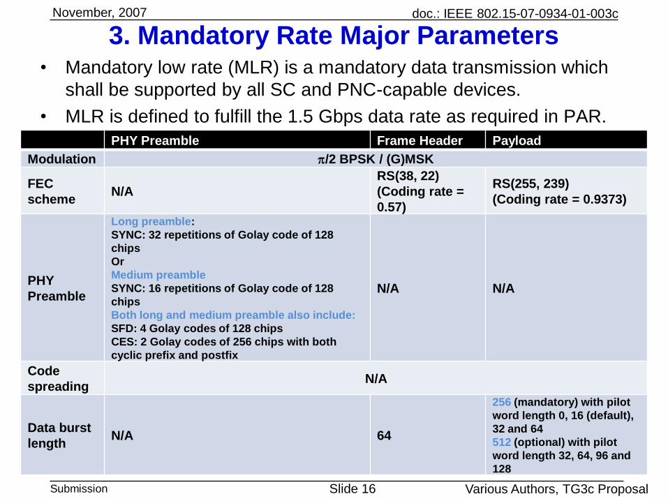
3. Mandatory Rate Major Parameters• Mandatory low rate (MLR) is a mandatory data transmission which
shall be supported by all SC and PNC-capable devices.
• MLR is defined to fulfill the 1.5 Gbps data rate as required in PAR.
PHY Preamble Frame Header Payload
Modulation p/2 BPSK / (G)MSK
FEC
schemeN/A
RS(38, 22)
(Coding rate =
0.57)
RS(255, 239)
(Coding rate = 0.9373)
PHY
Preamble
Long preamble:
SYNC: 32 repetitions of Golay code of 128
chips
Or
Medium preamble
SYNC: 16 repetitions of Golay code of 128
chips
Both long and medium preamble also include:
SFD: 4 Golay codes of 128 chips
CES: 2 Golay codes of 256 chips with both
cyclic prefix and postfix
N/A N/A
Code
spreadingN/A
Data burst
lengthN/A 64
256 (mandatory) with pilot
word length 0, 16 (default),
32 and 64
512 (optional) with pilot
word length 32, 64, 96 and
128
doc.: IEEE 802.15-07-0934-01-003c
Submission Slide 17
November, 2007
Various Authors, TG3c Proposal
3. Frame configuration
RS(38,22) RS(255,239)
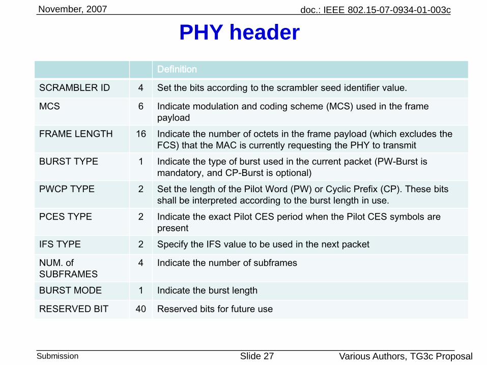
Frame header (22 octets) (PHY header (10 octets) + MAC header (10 octets) + and HCS(2 octets))
Frame payload(0~65531 octets) + FCS(4 octets)
FEC
Long or medium preamble
PHY Preamble (Long) Frame header (with pilot word) Payload (with pilot word)
Suitable for power limited and near line of sight communications with transmission speed ranging from low to high, for power efficient and low cost / portable device applications
1. Bit rates (PHY-SAP)
50 Mbps to 6Gbps, Various modulations and FEC together with FDE allows SC mode operation to realize from 1 Gbps class applications to several Gbps applications easier with proper header and preamble protection
2. Operation environments
Suitable for LOS and NLOS with FDE (Frequency domain equalizer)
3. Transmission range
10 m coverage by common mode in both LOS and NLOS environments, Higher bit rates with narrower coverage for personal area network
4. Applications:
SC allows low number of bit A/D converter implementation of receivers while a couple of Gbps are easily achievable resulting in very low power and high speed applications mandatory for portable terminal applications
5. MAC
Required MAC modifications are minimal to handle “strong directivity of millimeter wave” and a straight forward implementation is feasible
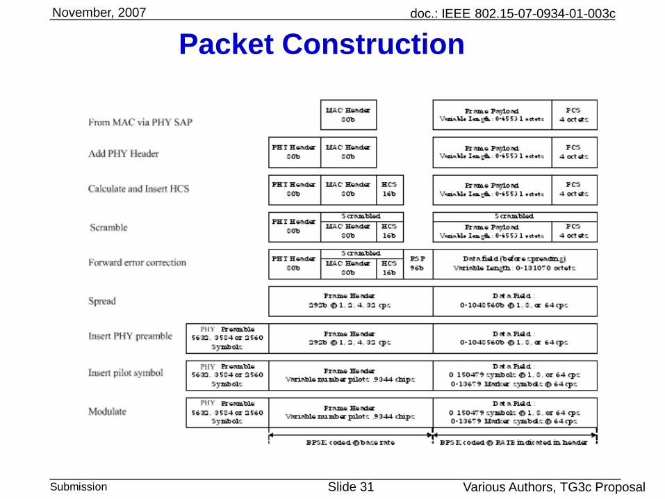
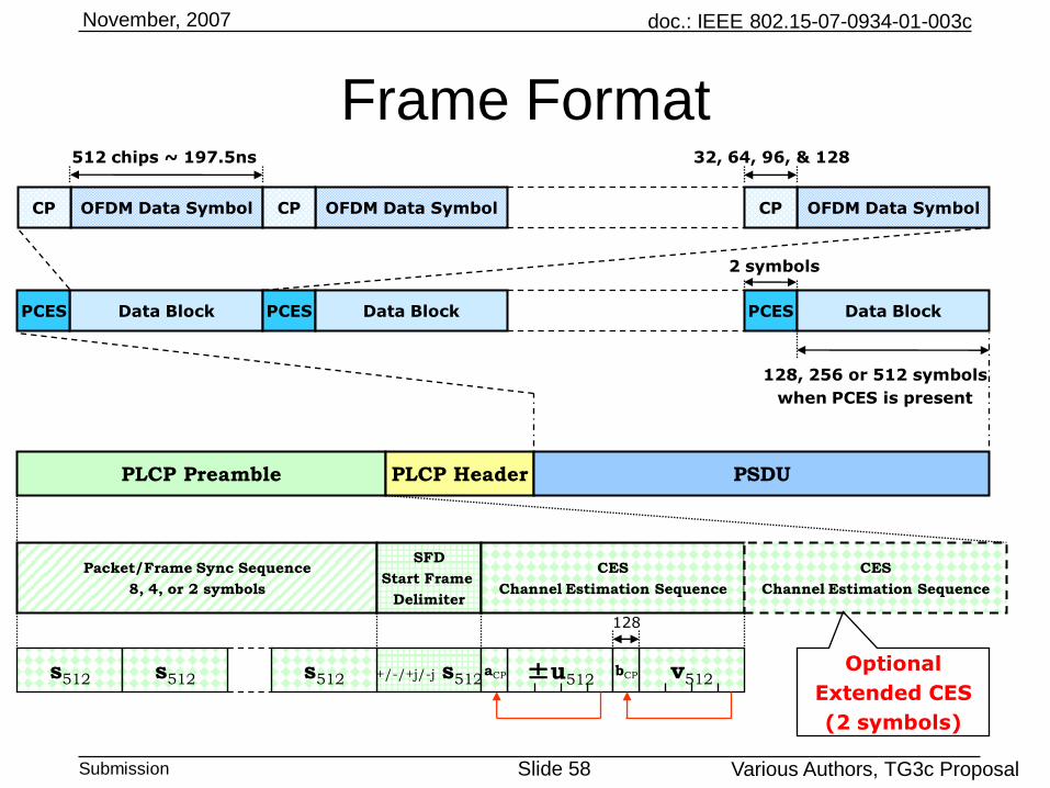
Frame payload encoding process:• Computing FCS over frame payload,• Appending the FCS to the frame payload,• Scrambling the resulting combination• Encoding the scrambled data• Spreading the encoded and scrambled data• Modulating the encoded and scrambled data• Building bursts form the spread, encoded and scrambled data • Inserting Pilot Channel Estimation Symbol fields into the data
doc.: IEEE 802.15-07-0934-01-003c
Submission Slide 31
November, 2007
Various Authors, TG3c Proposal
Packet Construction
doc.: IEEE 802.15-07-0934-01-003c
Submission Slide 32
November, 2007
Various Authors, TG3c Proposal
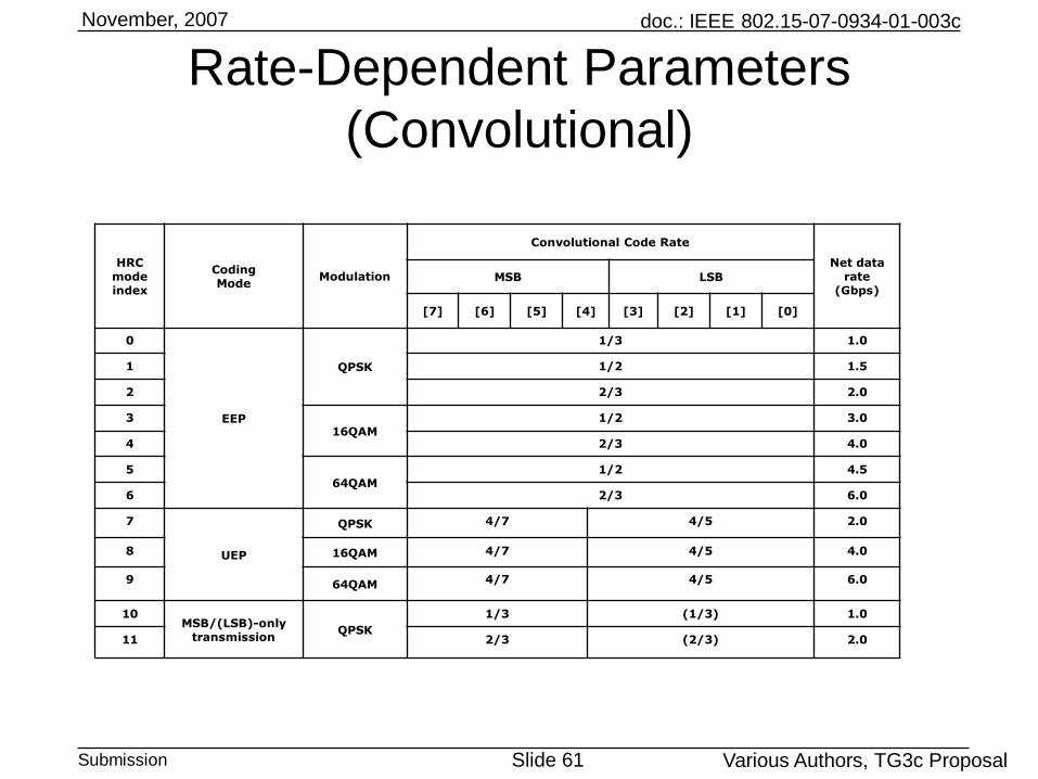
Base header rate-dependent parameters
Header Rate Chip Rate Modulation Spreading FEC FEC Pilot Word Burst Length Coded Bits
Mbps MHz Scheme Code Length Type Rate Length (chips) (chips) Per Burst
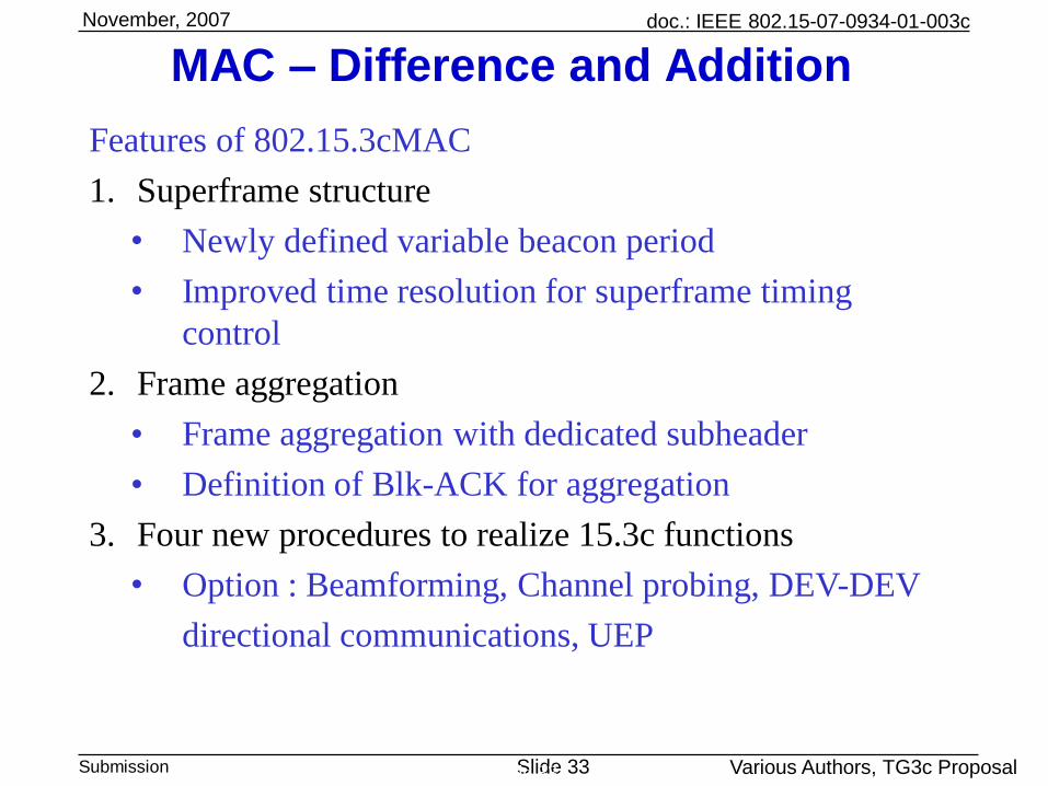
• Newly defined variable beacon period (BP) up to 256usMultiple beacon support of “omni”* and directional beacons in CR, OFDM/OOK beacons as
well• Contention Access Period (CAP) based on CSMA/CA• Channel Time Allocation Period (CTAP) based on TDMA
• Improved time resolution of 9ns (16symbols/1.728Gsps) for superframe timing control
Modification of piconet synchronization parameters
• Superframe duration (3 octets from 2 octets in 15.3b)
• CAP end time (3 octets from 2 octets in 15.3b)“Omni”: meaning to cover all directions by omni antenna or part of omni antenna coverage which is planned to be covered by the directional antenna
Omnibeacon
BP SIFS CAP CTAP
Long preamble(5632 symbols)
Frame header(22 octets)
Beacon payload
Piconet synchronization parameters(25 octets)
BSID IE(8~34 octets)
3.26 us 6.52 us
Time token(6 octets)
FCS(4 octets)
2.5 us
1.728 Gsymbol/s
Superframe duration(3 octets)
CAP end time(3 octets)
Max TX power level(1 octet)
Piconet mode(1 octet)
PNC response(1 octet)
PNC address(8 octets)
Up to 65535 us
Beacon period(2 octets)
doc.: IEEE 802.15-07-0934-01-003c
Submission Slide 35
November, 2007
Various Authors, TG3c Proposal
Aggregation and Blk-ACK
Slide 35
•MSB subframe
•LSB subrame
•MSB and LSB combined subframeOctets:4
FCS
2
SubFrame ID
block-n
...
...
1
Number of
SubFrames
blocked
10
MAC header
2
SubFrame ID
block-1
Block ACK
Subheader
b14
LSB
indication
b12-b9
Subframe ID
b8-b0
MSDU
number
Bits: b15
Reserved bits MSB
indication
b13
preamblePHY
header(10 octets)
MAC header
(10 octets)HCS
MAC Subheader
Subframe 1 ... Subframe nHCS
(subheaders)RS parity
bitsRS parity
bits
MCS information
(6 bits)
FCS information
(1 bit)
MSDUnumber(9 bits)
Subframe length
(12 bits)
Retransmissionpolicy(1 bits)
Reserved(4 bits)
Subheader #1(40bits/subframe)
Subheader #2(40bits/subframe)
Subheader #n(40bits/subframe)
...
Subframe Information
(2 bits)
Subframe ID
(4 bits)
UEP mapping indication
(1bit)
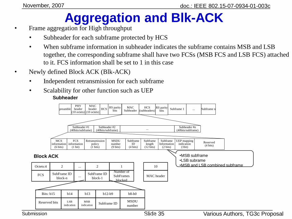
• Frame aggregation for High throughput
• Subheader for each subframe protected by HCS
• When subframe information in subheader indicates the subframe contains MSB and LSB
together, the corresponding subframe shall have two FCSs (MSB FCS and LSB FCS) attached
to it. FCS information shall be set to 1 in this case
• Newly defined Block ACK (Blk-ACK)
• Independent retransmission for each subframe
• Scalability for other function such as UEP
doc.: IEEE 802.15-07-0934-01-003c
Submission Slide 36
November, 2007
Various Authors, TG3c Proposal
MAC New operation procedures and primitives
Slide 36
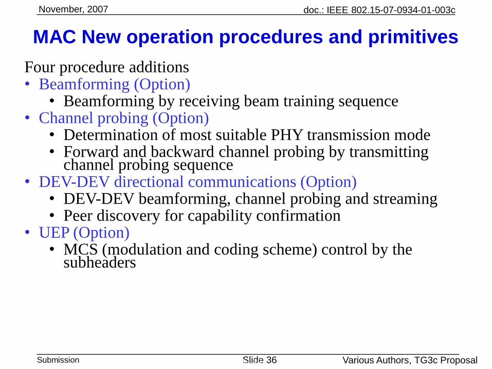
Four procedure additions • Beamforming (Option)
• Beamforming by receiving beam training sequence• Channel probing (Option)
• Determination of most suitable PHY transmission mode• Forward and backward channel probing by transmitting
UEP (3/3)• UEP information request command : This command is sent by any DEV to other DEV including PNC to request UEP scheme supported and UEP MCSs supported at the target DEV
Fig. UEP information request command format
• UEP information response command : This command is sent by the target DEV in response to originating DEV’s request to let the originating DEV know which UEP schemes are supported and
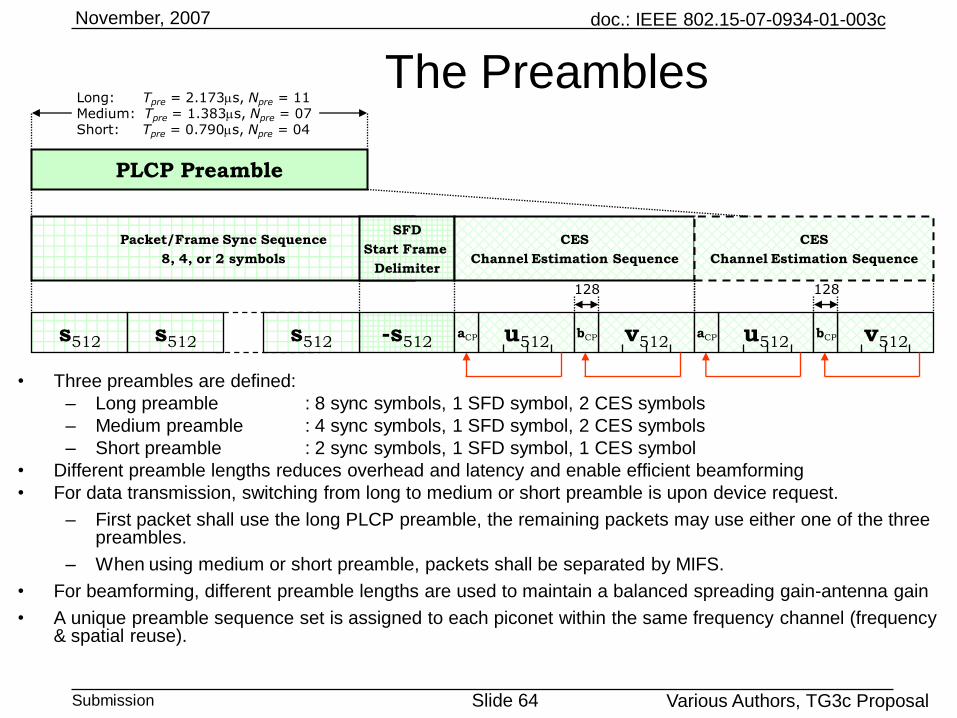
The Preambles• Four preamble sequence sets (labeled by the parameter m) are provided for the
purpose of frequency/spatial reuse
• A preamble sequence set consists of a base sequence s512,m and two CES sequences
u512,m and v512,m.
• The length 512 base sequence s512,m is the Kronecker product of a length 4 cover
sequence, c4,m and a length 128 modified Golay sequence u128,m.
s512,m[n] = c4,m[floor(n/128)]×u128,m[n mod 128] n=0:511
• The cover sequences and modified Golay sequences are listed in Tables 1 & 2
respectively.
• The base sequences occupy four non-overlapping frequency bin sets, and therefore are
orthogonal in time and frequency domain. The mth base sequence occupies frequency
bins m, m+4, m+8, m+12, …
• Modified Golay sequences, are obtained from Golay sequences using time (or
frequency) domain filtering to guarantee that only the used subcarriers are populated
rather than the entire 512 subcarriers.
doc.: IEEE 802.15-07-0934-01-003c
Submission Slide 66
November, 2007
Various Authors, TG3c Proposal
• The length 512 CES sequences u512,m and v512,m are modified complementary Golay sequences derived from Golay sequences a512,m and b512,m . They are listed in Table 3.
• Modified complementary Golay sequences enable perfect channel estimation in both time and frequency domains
– The Golay matched filter (shown before) can be used to provide simultaneously matched filter outputs to codes a and b. Combining the two outputs appropriately provide a perfect channel estimation in time domain;
– Frequency domain channel estimation is done in the conventional way. The complementarity property is conserved in frequency domain.
• OFDM systems can benefit from time-domain channel estimation due to dimensionality (ranking) issue;
• The Pilot CES (PCES) field is an optional field. When present, it is equivalent to the CES field and is repeated periodically to allow channel tracking. Three periods are provided which correspond to pedestrian speeds of 1, 3, and 6m/s.
• The receiver may use the efficient 2-levels (on I & Q) low-complexity Golay matched filter shown above for packet and frame detection.
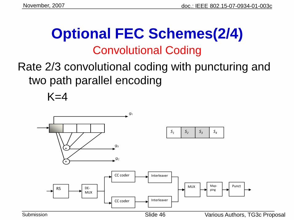
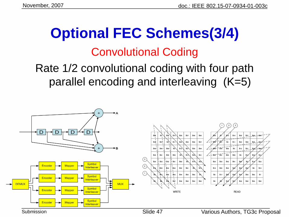
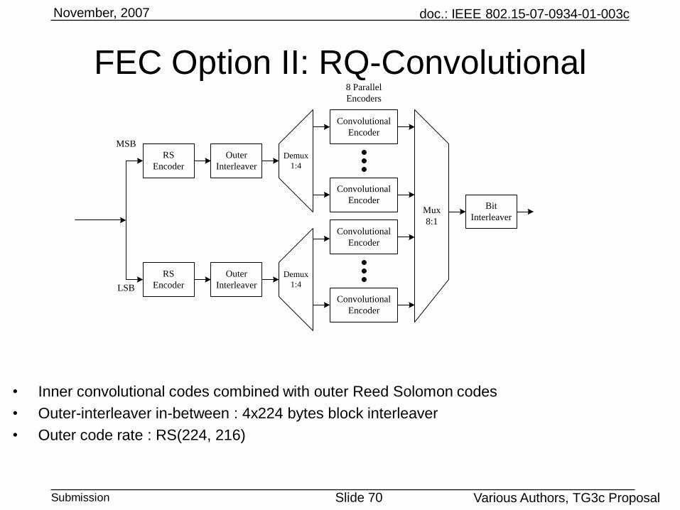
• Data multiplexer combines data from all convolutional encoders
• EEP Mux / Interleaver
– Bit interleaver size: 48
– A1…A6 come from encoder A, and similarly for others
FEC Option II: RS-Convolutional
A1 E5 D3 C1 G5 F3 E1 A5 H3 G1 C5 B3
B2 F6 E4 D2 H6 G4 F2 B6 A4 H2 D6 C4
C3 B1 F5 E3 D1 H5 G3 F1 B5 A3 H1 D5
D4 C2 G6 F4 E2 A6 H4 G2 C6 B4 A2 E6
I
MSB
I
LSB
Q
MSB
Q
LSB
Mux
8:1
Bit
Interleaver
From CC 1: A
From CC2: B
From CC3: C
From CC4: D
From CC5: E
From CC6: F
From CC7: G
From CC8: H
• UEP-Mapping Mux/Interleaver: Overall bit interleaver size 48
A1 C3 A5 B1 D3 B5 C1 A3 C5 D1 B3 D5
B2 D4 B6 C2 A4 C6 D2 B4 D6 A2 C4 A6
E1 G3 E5 F1 H3 F5 G1 E3 G5 H1 F3 G5
F2 H4 F6 G2 E4 G6 H2 F4 H6 E2 G4 E6
doc.: IEEE 802.15-07-0934-01-003c
Submission Slide 73
November, 2007
Various Authors, TG3c Proposal
FEC Option II: RS-Convolutional
• UEP-Coding Mux/Interleaver
– Overall bit interleaver size 96
– For first half cycle of 48 bits: A1…A7 come from encoder A,
similarly for BCD; E1…E5 come from encoder E, similarly for
FGH
– For second half cycle of 48 bits: A1…A7 come from encoder A, similarly for BCD;
E1…E5 come from encoder E, similarly for FGH
A1 E1 C7 B6 G3 E5 D4 A5 H2 F4 C3 B2
B2 F3 D7 C6 H5 G2 E4 B5 B5 H1 D3 C2
C1 A7 F2 D6 C5 H4 G1 E3 E3 A3 G5 D2
D1 B7 G4 F1 D5 A6 H3 F5 F5 B3 A2 E2
B1 E1 C7 B6 G3 E5 D4 A5 H2 F4 C3 B2
C1 F3 D7 C6 H5 G2 E4 B5 B5 H1 D3 C2
C1 A7 F2 D6 C5 H4 G1 E3 E3 A3 G5 D2
D1 B7 G4 F1 D5 A6 H3 F5 F5 B3 A2 E2
doc.: IEEE 802.15-07-0934-01-003c
Submission Slide 74
November, 2007
Various Authors, TG3c Proposal
• Optimized binary interleaver based on an iterative structure [1-4]
• Effectively maximizes both intra- and inter- symbols interleaving spreading
• Efficiently improves decoder performance
( )
, ( )j
p qI k(2)
, ( )p qI k
I I Ik I
, ( )p qI k
( )
, ( )j
p qI k(2)
, ( )p qI k
I I Ik I
, ( )p qI k
) ) ) )
) KK
j
qp
j
qp
KKqp
j
qpINOUT
IpkpqkkI
kpkpqkkI
kIXkX
)1(
,
)(
,
)0(
,
)(
,
a
a
parameterOffset :
parametersr Interleave : , ,
size,Block :
p
K
jqp
K
a
FEC Option II: Binary Interleaving
doc.: IEEE 802.15-07-0934-01-003c
Submission Slide 75
November, 2007
Various Authors, TG3c Proposal
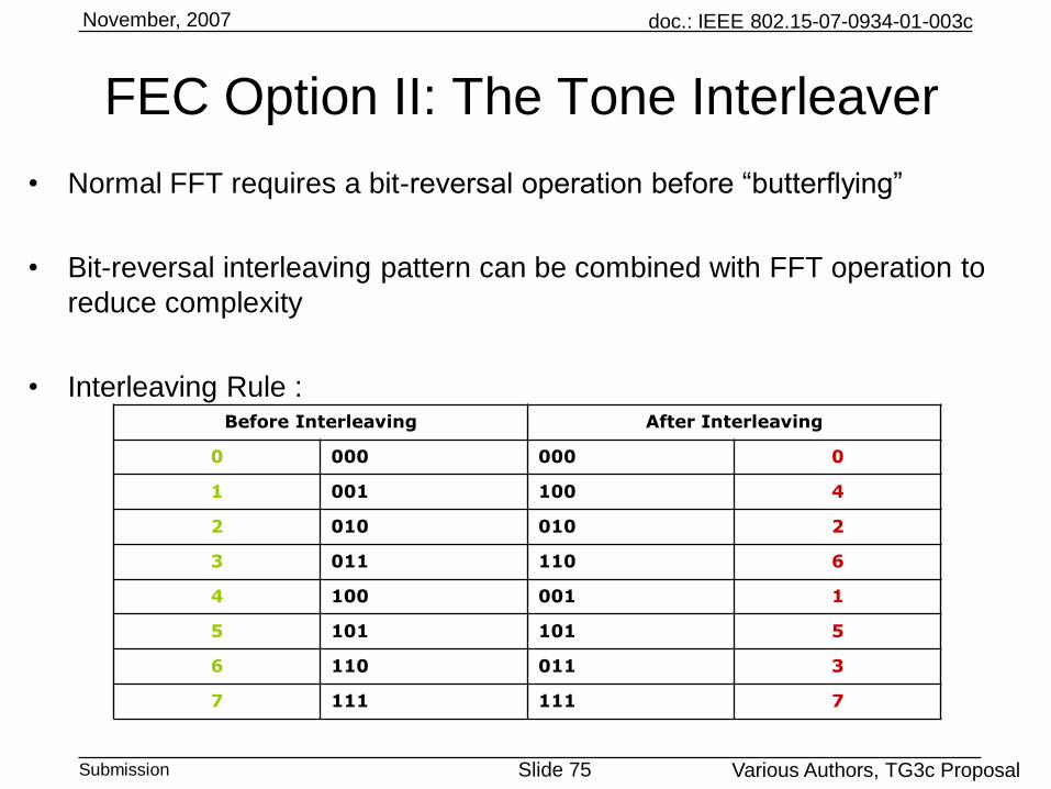
• Normal FFT requires a bit-reversal operation before “butterflying”
• Bit-reversal interleaving pattern can be combined with FFT operation to
reduce complexity
• Interleaving Rule : Before Interleaving After Interleaving
0 000 000 0
1 001 100 4
2 010 010 2
3 011 110 6
4 100 001 1
5 101 101 5
6 110 011 3
7 111 111 7
FEC Option II: The Tone Interleaver
doc.: IEEE 802.15-07-0934-01-003c
Submission Slide 76
November, 2007
Various Authors, TG3c Proposal
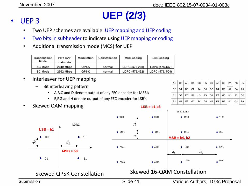
Normal & Skewed Constellation for UEP-Mapping
d1
2d1
0100 0110 1110 1100
0101 0111 1111 1101
0001 0011 1011 1001
0000 00101010 1000
b0 b1 b2 b3
d2
2d
2
16-QAM
d1
00 10
01 11
d2
b0 b1
QPSK
MSB = b0
LSB = b1
MSB = b0, b2
LSB = b1,b3
+3+1-1-3+1
+3
-1
-3
00 10 01 10 11 10 10 10
00 11 01 11 11 11 10 11
00 01 01 01 11 01 10 01
00 00 01 00 11 00 10 00
b4kb4k+1b4k+2b4k+3
Ik
Qk
1110
0100
Ik
Qk
+1-1
b2kb2k+1
+1
-1
doc.: IEEE 802.15-07-0934-01-003c
Submission Slide 77
November, 2007
Various Authors, TG3c Proposal
Optional
Beamforming I
doc.: IEEE 802.15-07-0934-01-003c
Submission Slide 78
November, 2007
Various Authors, TG3c Proposal
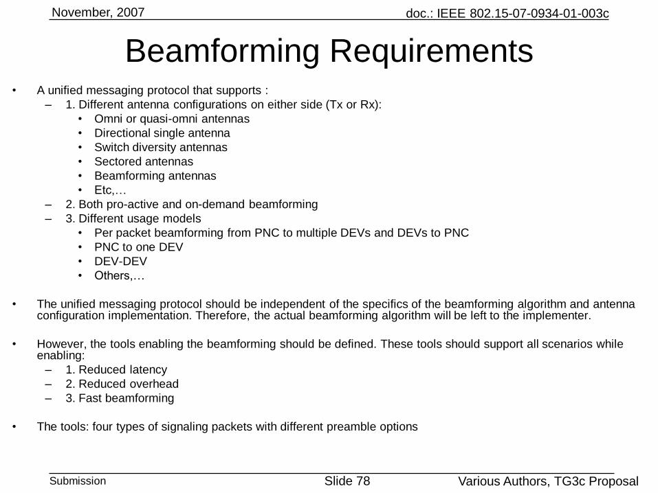
Beamforming Requirements• A unified messaging protocol that supports :
– 1. Different antenna configurations on either side (Tx or Rx):
• Omni or quasi-omni antennas
• Directional single antenna
• Switch diversity antennas
• Sectored antennas
• Beamforming antennas
• Etc,…
– 2. Both pro-active and on-demand beamforming
– 3. Different usage models
• Per packet beamforming from PNC to multiple DEVs and DEVs to PNC
• PNC to one DEV
• DEV-DEV
• Others,…
• The unified messaging protocol should be independent of the specifics of the beamforming algorithm and antenna configuration implementation. Therefore, the actual beamforming algorithm will be left to the implementer.
• However, the tools enabling the beamforming should be defined. These tools should support all scenarios while enabling:
– 1. Reduced latency
– 2. Reduced overhead
– 3. Fast beamforming
• The tools: four types of signaling packets with different preamble options
doc.: IEEE 802.15-07-0934-01-003c
Submission Slide 79
November, 2007
Various Authors, TG3c Proposal
Pro-Active Beamforming
• Pro-active beamforming is useful when the PNC is the source of data to one or multiple DEVs.
• Usage model example: Kiosk, STB, Laptop:
– The PNC is the source of data to multiple DEVs;
– The PNC can send each packet in a different direction, optimized to the destined device.
Beacon
Period
CAP
(Contention Access Period)
CTAP
(Channel Time Allocation Period)
Q-Omni
Beacon
#1
Directional
Beacon
#(m-1)×N+1
Directional
Beacon
#(m-1) ×N+2
Directional
Beacon
#m×N
Q-Omni
Beacon
#2
Q-Omni
Beacon
#L
Beacon Period for Superframe # m
Superframe # m
Packet
To User #1
Direction #j1
Packet
To User #2
Direction #j2
Packet
To User #L
Direction #jL
MIFS SIFS or MIFS
SIFS or MIFS
Q-CAP
#1
Q-CAP
#2
Q-CAP
#L
Possibly and/or N Directional CAPs as Well
doc.: IEEE 802.15-07-0934-01-003c
Submission Slide 80
November, 2007
Various Authors, TG3c Proposal
Pro-Active Beamforming
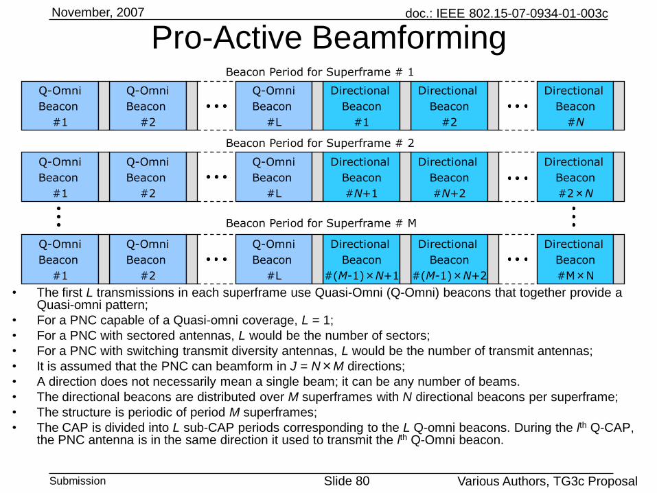
• The first L transmissions in each superframe use Quasi-Omni (Q-Omni) beacons that together provide a Quasi-omni pattern;
• For a PNC capable of a Quasi-omni coverage, L = 1;
• For a PNC with sectored antennas, L would be the number of sectors;
• For a PNC with switching transmit diversity antennas, L would be the number of transmit antennas;
• It is assumed that the PNC can beamform in J = N×M directions;
• A direction does not necessarily mean a single beam; it can be any number of beams.
• The directional beacons are distributed over M superframes with N directional beacons per superframe;
• The structure is periodic of period M superframes;
• The CAP is divided into L sub-CAP periods corresponding to the L Q-omni beacons. During the lth Q-CAP, the PNC antenna is in the same direction it used to transmit the lth Q-Omni beacon.
Q-Omni
Beacon
#1
Directional
Beacon
#1
Directional
Beacon
#2
Directional
Beacon
#N
Q-Omni
Beacon
#2
Q-Omni
Beacon
#L
Q-Omni
Beacon
#1
Directional
Beacon
#N+1
Directional
Beacon
#N+2
Directional
Beacon
#2×N
Q-Omni
Beacon
#2
Q-Omni
Beacon
#L
Q-Omni
Beacon
#1
Directional
Beacon
#(M-1)×N+1
Directional
Beacon
#(M-1)×N+2
Directional
Beacon
#M×N
Q-Omni
Beacon
#2
Q-Omni
Beacon
#L
Beacon Period for Superframe # 1
Beacon Period for Superframe # 2
Beacon Period for Superframe # M
doc.: IEEE 802.15-07-0934-01-003c
Submission Slide 81
November, 2007
Various Authors, TG3c Proposal
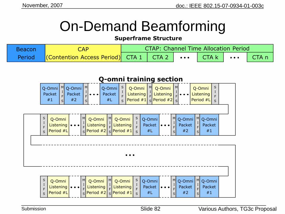
• On-demand beamforming will take place in the CTA allocated to the link between the TWO DEVs or PNC and a DEV;
• Q-omni phase:– DEV1 starts its first transmission with L1 Q-omni packets followed by L1 corresponding Q-omni listening
periods;
– DEV1 keeps repeating this section until DEV2 sends back a response
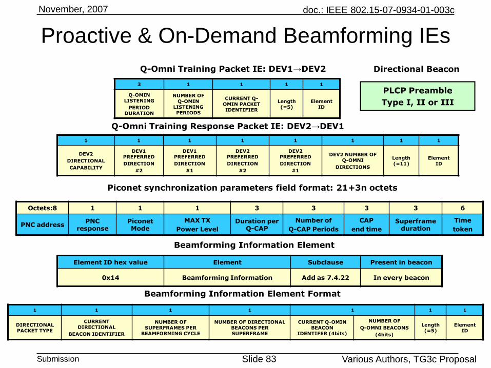
– Each Q-omni training packet would contain the “Q-omni training packet IE”;
– DEV2, capable of L2 Q-Omni directions, will set its reception direction to one of the L2 directions and listens to DEV1 first L1 transmissions and stores L1 LQFs. DEV2 moves to a new direction and listen to DEV1 second period of L1 transmissions. DEV2 continue to do so until an adequate LQF. Alternatively, DEV2 may choose to listen using all L2 directions than find the best LQF.
– At the end of this phase, DEV1 and DEV2 would know the best Q-Omni directions combination to exchange further data.
– Using the “Q-omni training response packet IE”, DEV2 would inform DEV1 of its Q-omni capabilities, i.e. L2, as well as its own best 1st direction and 2nd direction that it will use for all messaging. Furthermore, DEV2 would inform DEV1 of the best 1st and 2nd direction it found out from the L1 direction. DEV1 best Q-omni direction would be labeled l1, and DEV2 best Q-omni-direction would be labeled l2. DEV2 informs DEV1 of its directional capability as well.
On-Demand Beamforming
doc.: IEEE 802.15-07-0934-01-003c
Submission Slide 82
November, 2007
Various Authors, TG3c Proposal
Beacon
Period
CAP
(Contention Access Period)
CTAP: Channel Time Allocation Period
CTA 1 CTA 2 CTA nCTA k
Q-Omni
Packet
#1
M
I
F
S
Q-Omni
Packet
#2
M
I
F
S
Q-Omni
Packet
#L
S
I
F
S
Q-Omni
Listening
Period #1
M
I
F
S
Q-Omni
Listening
Period #2
M
I
F
S
Q-Omni
Listening
Period #L
S
I
F
S
Q-Omni
Packet
#1
M
I
F
S
Q-Omni
Packet
#2
M
I
F
S
Q-Omni
Packet
#L
S
I
F
S
Q-Omni
Listening
Period #1
M
I
F
S
Q-Omni
Listening
Period #2
M
I
F
S
Q-Omni
Listening
Period #L
S
I
F
S
Q-omni training section
Q-Omni
Packet
#1
M
I
F
S
Q-Omni
Packet
#2
M
I
F
S
Q-Omni
Packet
#L
S
I
F
S
Q-Omni
Listening
Period #1
M
I
F
S
Q-Omni
Listening
Period #2
M
I
F
S
Q-Omni
Listening
Period #L
S
I
F
S
Superframe Structure
On-Demand Beamforming
doc.: IEEE 802.15-07-0934-01-003c
Submission Slide 83
November, 2007
Various Authors, TG3c Proposal
3 1 1 1 1
Q-OMIN LISTENING
PERIOD DURATION
NUMBER OF Q-OMIN
LISTENING PERIODS
CURRENT Q-OMIN PACKET IDENTIFIER
Length (=5)
Element ID
Q-Omni Training Packet IE: DEV1→DEV2
1 1 1 1 1 1 1 1
DEV2
DIRECTIONAL
CAPABILITY
DEV1 PREFERRED
DIRECTION
#2
DEV1 PREFERRED
DIRECTION
#1
DEV2 PREFERRED
DIRECTION
#2
DEV2 PREFERRED
DIRECTION
#1
DEV2 NUMBER OF Q-OMNI
DIRECTIONS
Length (=11)
Element ID
Q-Omni Training Response Packet IE: DEV2→DEV1
Proactive & On-Demand Beamforming IEs
Octets:8 1 1 1 3 3 3 3 6
PNC addressPNC
responsePiconet Mode
MAX TX
Power Level
Duration per Q-CAP
Number of
Q-CAP Periods
CAP
end time
Superframe duration
Time
token
Piconet synchronization parameters field format: 21+3n octets
Element ID hex value Element Subclause Present in beacon
0x14 Beamforming Information Add as 7.4.22 In every beacon
Beamforming Information Element
1 1 1 1 1 1 1
DIRECTIONAL PACKET TYPE
CURRENT DIRECTIONAL
BEACON IDENTIFIER
NUMBER OF SUPERFRAMES PER
BEAMFORMING CYCLE
NUMBER OF DIRECTIONAL BEACONS PER SUPERFRAME
CURRENT Q-OMIN BEACON
IDENTIFER (4bits)
NUMBER OF
Q-OMNI BEACONS
(4bits)
Length (=5)
Element ID
Beamforming Information Element Format
PLCP Preamble
Type I, II or III
Directional Beacon
doc.: IEEE 802.15-07-0934-01-003c
Submission Slide 84
November, 2007
Various Authors, TG3c Proposal
• Directional phase:
– DEV1 uses an R-cycle procedure to do the beamforming;
– The R cycles may happen within one CTA or may be distributed over M superframes;
– Each cycle is made from K sub-cycles, where N and K can change from one cycle to another. This will allow for different search algorithms such as random and binary search, and differentiating between acquisition and tracking;
– Each cycle is preceded by an Q-omni transmission outlining the structure of the current cycle;
– Each sub-cycle consists of N directional preambles followed by an Q-omni listening period;
– During data communication, DEV1 may still choose to transmit a sub-cycle every superframe to allow DEV2 to continuously track the beams. If DEV2 finds a better direction, it can inform DEV1 to transmit next packets using the new direction by encoding the field “Antenna Direction” in the header appropriately.
On-Demand Beamforming
doc.: IEEE 802.15-07-0934-01-003c
Submission Slide 85
November, 2007
Various Authors, TG3c Proposal
Beacon
Period
CAP
(Contention Access Period)
CTAP: Channel Time Allocation Period
Superframe Structure
CTA 1 CTA 2 CTA nCTA k
Q-Omni
Packet
S
I
F
S
Directional
preamble
#N
Q-Omni
Listening
Period
CTA k
M
I
F
S
M
I
F
S
S
I
F
S
Directional
preamble
#1
Directional
preamble
#2
Directional
preamble
#2N
M
I
F
S
Directional
preamble
#N+1
Directional
preamble
#N+2
S
I
F
S
Directional
preamble
#(r-1)×N+1
M
I
F
S
Directional
preamble
#(r-1)×N+2
Directional
preamble
#r×N
S
I
F
S
Q-Omni
Listening
Period
Q-Omni
Listening
Period
Q-Omni
Listening
Period
S
I
F
S
S
I
F
S
S
I
F
S
S
I
F
S
S
I
F
S
M
I
F
S
Sub-cycle
1 1 1 1 3 1 3 1 1
DIRECTIONAL PREAMBLE TYPE
NUMBER OF SUPERFRAMES PER
BEAMFORMING CYCLE
NUMBER OF SUB-CYCLES PER
SUPERFRAME
NUMBER OF DIRECTIONAL
PREAMBLES PER SUB-CYCLE
Q-OMIN LISTENING
PERIOD DURATION
CURRENT Q-OMIN PACKET IDENTIFIER
CTA END TIME
Length (=11)
Element ID
Q-Omni Packet Information Element
1 … 1 1 1 1
LQF-N … LQF-2 LQF-1Length (=N)
Element ID
Beamforming Report Information Element
On-Demand Beamforming
doc.: IEEE 802.15-07-0934-01-003c
Submission Slide 86
November, 2007
Various Authors, TG3c Proposal
Optional
Beamforming II
doc.: IEEE 802.15-07-0934-01-003c
Submission Slide 87
November, 2007
Various Authors, TG3c Proposal
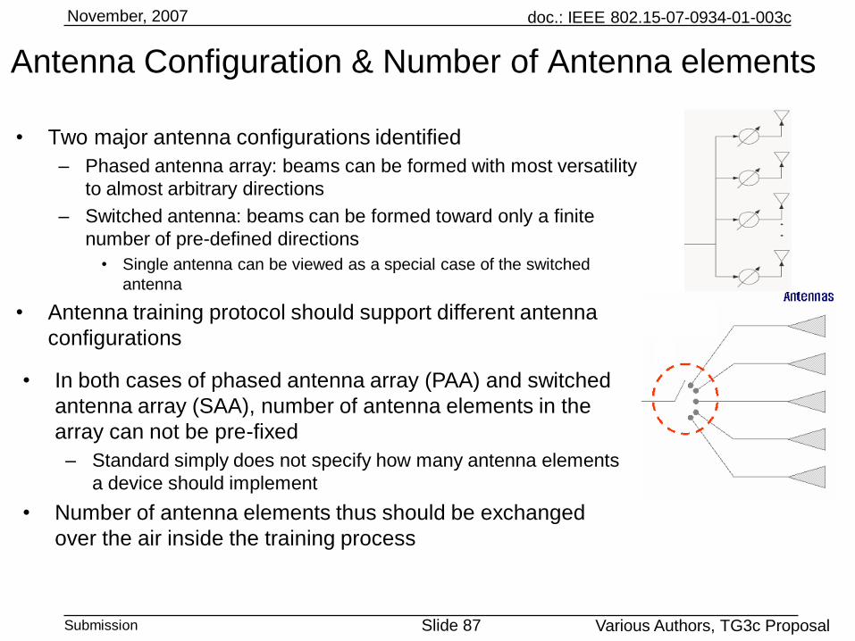
• Two major antenna configurations identified
– Phased antenna array: beams can be formed with most versatility
to almost arbitrary directions
– Switched antenna: beams can be formed toward only a finite
number of pre-defined directions
• Single antenna can be viewed as a special case of the switched
antenna
• Antenna training protocol should support different antenna
configurations
Antenna Configuration & Number of Antenna elements
• In both cases of phased antenna array (PAA) and switched
antenna array (SAA), number of antenna elements in the
array can not be pre-fixed
– Standard simply does not specify how many antenna elements
a device should implement
• Number of antenna elements thus should be exchanged
over the air inside the training process
doc.: IEEE 802.15-07-0934-01-003c
Submission Slide 88
November, 2007
Various Authors, TG3c Proposal
Octets: 1 1 2 2 …… 1 3
IE index Length SC mode support OFDM mode support …… Explicit / implicit Antenna Support
Bits: 8 8 4 4
Number of TX elements Number of RX elements TX antenna type RX antenna type
• Antenna info (antenna type and number of antennas) are
exchanged in the association stage. Example:
Antenna Info Exchange
• Depending on the antenna types of STA1, and STA2;
• 4 possible combinations
• 1) PAA to PAA
• 2) PAA to SAA
• 3) SAA to PAA
• 4) SAA to SAA
• Apply optimized training sequence for each combination