PROJECT LASER-CELL (278674) D3.1 LASER-SOURCE SELECTION 1 / 64 PROJECT LASER-CELL With funding from: Deliverable number Deliverable name Date Author D3.1 LASER SOURCE SELECTION 31 March 2012 CNC Summary This document tells which laser type is the state of the art for laser drilling and laser sintering processes at the moment. Distribution All consortium members + project officer Version 1.0 Work Package 3 PROJECT LASER-CELL: Innovative cell and stack design for stationary industrial applications using novel laser processing techniques LASER-CELL CONSORTIUM Beneficiary number Beneficiary name Short name Country 1 (Coordinator) AFC Energy plc AFCEN UK 2 CenCorp Oyj CNC Finland 3 Teknologian Tutkimuskeskus – Technical Research Centre VTT Finland 4 Air Products Ltd AIRP UK 5 Nanocyl S. A. NCL Belgium 6 Universität Duisburg – Essen UDE Germany
Summary This document tells which laser type is the state of the art for laser drilling and laser sintering processes at the moment.
Distribution All consortium members + project officer
Version 1.0 Work Package 3
PROJECT LASER-CELL: Innovative cell and stack design for stationary industrial applications usingnovel laser processing techniques
LASER-CELL CONSORTIUMBeneficiary number Beneficiary name Short name Country 1 (Coordinator) AFC Energy plc AFCEN UK 2 CenCorp Oyj CNC Finland 3 Teknologian Tutkimuskeskus – Technical Research Centre VTT Finland 4 Air Products Ltd AIRP UK 5 Nanocyl S. A. NCL Belgium 6 Universität Duisburg – Essen UDE Germany
Part 2, Laser sintering .................................................................................................................................14
5. APPLICATIONS AND CASE STUDIES ......................................................................................................40
Example of laser sintering of Nickel alloy .............................................................................................40
PROJECT LASER-CELL (278674) DELIVERABLE 3.1
3 / 64
Fabrication of modified graphite bipolar plates .......................................................................................44
Laser sintering of carbon nanotube-reinforced ceramic nanocomposites ................................................47
Porous biocompatible implants and tissue scaffolds synthesized by selective laser sintering ...................48
Manufacturing of fine-structured 3D porous filter elements by selective laser melting ...........................50
Sintering PCL powder to fabricate a highly porous scaffold for application in cardiac tissue engineering .52
PRE-TESTS AT VTT .......................................................................................................................................54
In the Part 1 this deliverable tells which laser source is the state of the art for laser drilling process at the moment. Two different lasers were tested for drilling. Those lasers seemed to be the state of the art lasers of its kind according to literature and technical specifications. This deliverable only considers finding out the laser capabilities. This paper doesn’t take account on other factors that affects drilling efficiency such as optical setup. Lot of drills was made with different materials and thicknesses.
All experiments within these tests were done by Cencorp within months M1-M4.
In the Part 2 a literature review has been carried out by VTT on laser sintering. The State of the Art has been supported by doing small size (1 cm x 1 cm) laser sintering pre-tests. Fiber and disk lasers are the choice at the moment for laser sintering of metals. They have only one major disadvantage, which is the poor absorption to polymers. For the same reason CO2 lasers are still used for laser sintering of plastics.
PROJECT LASER-CELL (278674) DELIVERABLE 3.1
6 / 64
Part 1, Laser Drilling
2 LASER SOURCES
When talking about the right laser source, it is not so clear to say which laser is the best because there is lot of factors that matters. One laser can be good for one application and other is better for second application. I.e. hole size and hole pattern plays a great role. That’s why the initial requirements of holes have to clarify before final selection can be done.
Two different kinds of lasers were selected for these tests. Those lasers were: “Jenoptiks JenLas disk IR70E” and “IPG YTTERBIUM PULSED FIBER LASER SPECIFICATION MODEL YLP-HP-2-1500-50-100”. Lasers were tested on manufactures site. Those lasers are best for drilling thin metals based on literature review.
Table 1. Specifications of laser sources used in the drilling tests
Laser JenLas® disk IR70E IPG YLP-HP-2-50-100 Wavelenght 1030 nm 1065 nm Polarization Linear Random Beam quality M² 1.2 M² 2 Nominal Output Power 65 W @ 30 kHz 100W Pulse Energy over 7 mJ @ 8 kHz limited to 2 mJ @ 50 kHz Pulse repetition rate 8-35 kHz 5-100 kHz Pulse lenght (typ.) 650-1600 ns 1500 ns Unit prize ~85 000 € ~100 000 €
Picture 1. Jenoptik disc laser JenLas IR70 and IPG fiber laser YTTERBIUM PULSED FIBER LASER SPECIFICATION MODEL YLP-HP-2-1500-50-100
PROJECT LASER-CELL (278674) DELIVERABLE 3.1
7 / 64
3 MATERIALS
This evaluation considered only laser drilling of metals. The main material for drilling efficiency evaluating was stainless steel. Although nickel has almost the same psychical characters as stainless steel, there are some differences on laser drilling process between these materials. That’s why also Nickel samples were drilled.
Table 2. Materials used for the drilling tests
150 µm 200 µm 250 µm 300 µm Stainless Steel x x x x
Nickel alloy 201 x
4 DRILLING METHOD AND SETUPS
Because the purpose of these experiments was to evaluate different lasers to each other, only small areas were drilled. Bigger area could cause material bending during the drilling process and laser comparison would be more difficult. Also only the center of scanner working field was used to be sure that the focus remains in the right spot all the time. (picture 2.)
Picture 2. Working area: All the experiments were done in the middle of scanner working area for minimizing the power density loss in the corners of working area caused by the scanner optics.
Hole pattern was following, each parameter was used with different repeat times. With this pattern it was easy to see how many pulses are needed for full penetration.
PROJECT LASER-CELL (278674) DELIVERABLE 3.1
8 / 64
Picture 3. Hole pattern
The drilling setups were build so that they are comparable with each other. Environment for the drilling was kept as similar as possible (picture 3. Drilling setups). In the next table are shown essential components used in tests.
Table 3. Components used in the tests
Component DiscLaser Fiber laser
Focal lenght 254 mm 300 mm Expander ratio
4 x 2 x
Calculated Spot size
45 µm 41 µm
Scanner SS-10 SS-20 Fixture same
PROJECT LASER-CELL (278674) DELIVERABLE 3.1
9 / 64
Picture 4. Setup for drilling tests with JenOptik laser (left) and setup with IPG laser (right)
With fiber laser the beam is delivered via optical fiber. That helps building the laser system. With disc laser the beam goes via reflecting mirrors in open air. That’s because the pulse energy is very high and that would damage the fiber.
5 RESULTS
Each drilled sample were studied properly to be sure which laser would suite better for laser drilling of metals. Best samples were photographed and measured with microscope.
There were two main criteria which defined the state- of–the-art laser: Holes per second rate and energy needed for a single hole.
PROJECT LASER-CELL (278674) DELIVERABLE 3.1
10 / 64
5.1 Holes/ second rate
Because great number of holes is needed in the final product, high holes/second -rate could decrease the production time of single plate remarkable. In the next table are shown the drilling rates of stainless steel for these two lasers.
Figure 1. Drilling speed comparison with different material thicknesses (Stainless Steel 150 µm to 300 µm)
Holes per second rate are much higher with fiber laser. This is mainly because fiber has higher repetition rate on pulses. It’s possible to penetrate approximately 20 µm for a single pulse, if more energy is added to one pulse, penetration depth won’t rise. The only thing that comes along with higher energy level is that the hole size will get bigger.
20002500300035004000450050005500600065007000
0,1 0,15 0,2 0,25 0,3 0,35
Hole
s/s
Material thickness [mm]
Drilling rate/second [Stainless Steel]
Fiber laser
Disc laser
PROJECT LASER-CELL (278674) DELIVERABLE 3.1
11 / 64
Figure 2. Pulse energy effect on hole size.
Picture 5. Pulse energy effect on hole entry size. Pulse energies 1mJ – 8 mJ from left to right The thermal effect is much more bigger when extra amount of energy is added to pulse. The hole is not so neat anymore. The entry side of hole is remarkable bigger when pulse energy is raised.
Picture 6. Pulse energy effect on hole exit size. Pulse energies 1mJ – 8 mJ from left to right. Hole size does not change so much on the backside when pulse energy is raised. But the HAZ area rise can be seen clearly.
5.2 Material removal rate
When porous material is wanted, lots of holes/mm is needed. The amount of holes marks but also hole size plays a great role when great porosity is needed. In theory the porosity percent rises when holes are very close to each other. But holes can’t be drilled very close together because they disturb each other. The
0,00
20,00
40,00
60,00
80,00
100,00
120,00
0 2 4 6 8 10
Hol
e si
ze [µ
m]
Pulse energy [mJ]
Pulse energy effeft on hole size [Nickel with disc laser]
entry µm
exit µm
PROJECT LASER-CELL (278674) DELIVERABLE 3.1
12 / 64
molten material sprites out from one hole to another and that drops the drilling speed because more pulses are needed for opening the holes. So holes can’t be too close together.
The hole is conical after laser drilling (picture 7.). That’s why is wise to define the free surface area from the exit side of the hole. Best shape of the hole after drilling would be cylinder, because then the free surface area on the backside would be the biggest.
Picture 7. Cross-section of a single hole.
Next figure compares the lasers based on the material removal rate. The values on the table are taken from samples when holes/second rate was maximum.
Figure 3. Hole sizes on exit side on maximum holes/second rate.
What can be seen on the table is that when holes/second rate is maximum there are only slight difference on the hole size (exit side) between fiber and disc lasers.
In case that if in the final product the hole size and hole amount don’t matter, lasers are also compared with achievable free surface area on the exit side of the hole. Next figure shows this comparison with stainless steel (thicknesses from 150 µm to 300 µm). It can be clearly seen in the figure that with thinner materials the Fiber laser wins easily.
0
510
1520
2530
3540
100 150 200 250 300 350
Hol
e siz
e EX
IT s
ide
Material thickness [µm]
Hole size on exit side
EXIT Fiber
EXIT Disc
PROJECT LASER-CELL (278674) DELIVERABLE 3.1
13 / 64
Figure 4. Achievable free surface area comparison.
6 CONCLUSION, LASER SELECTION
Laser is the best and in fact the only equipment available for drilling huge amount of very small holes. It depends on the material grade, hole shape, hole size, hole spacing and material thickness which is the best laser for the job. With metals and thicknesses tested the winner is quite clear: Fiber laser is the state of the art laser device for the job at the moment. Fiber lasers capability to high pulse repetition rate is essential factor for drilling great number of holes. Because every material has it limits of how deep pitch can be drilled for a single pulse.
Within these results it is clear that this day state of the art laser source is modified fiber laser because its frequency rate is best possible for drilling small holes to thin materials. In the next table is shown criteria why fiber laser is better for laser drilling of metals.
Table 4. Comparison table of drilling lasers
Fiber Disc Costs per hole x Prize per unit x Beam delivery method
x
Pulse repetition rate x Maximum pulse energy x Beam quality x Material removal rate x
012345678
100 150 200 250 300 350
Surf
ace
area
mm
^2
Material Tchickness [µm]
Achievable surface area/second on exit side
Fibre
Disc
PROJECT LASER-CELL (278674) DELIVERABLE 3.1
14 / 64
Part 2, Laser sintering
1. SINTERING PROCESS
Laser sintering
With the selective laser sintering, which is rapid prototype (RP) technology, fully functional parts can be create directly from powders without the use of any intermediate binders or any additional processing. In this technique solid objects are built layer-by-layer from data files. Materials that are sintered using laser energy are plastic, metal, ceramic powders or pre-coated sands. SLS not only reduces the time and cost of prototyping components, obtaining the same dimensional accuracy, surface finish and repeatability as common manufacturing process, but also reduces the energy intensity and the environmental impacts of the process. [4], [11]
The basic concept, common to all rapid prototyping techniques, is that any complex shape can be produced by the superposition of small thickness layers. In case of SLS, layers of 0.05 - 0.3 mm thickness are obtained by thermal binding of small particles that are agglomerated together by the action of a laser source whose wavelength depends of the powder adopted. CAD software is commonly used to decompose a 3D drawing into a sequence of thin layer whose shape is used to set the working area of the laser beam. After a layer is sintered at a predefined focal length, new uncured powder is levelled on a platform whose vertical adjustment (governed by a step-motor) allows re-focusing of the laser beam. [11]
Selective laser sintering has been developed at the University of Texas and was patented in 1989 [9], [5]. The first proper commercial system for laser-sintering was the Sinterstation 2000 from DTM Corp. of Austin, Texas, the result of the research and development by Deckard, Beaman and colleagues at UT and the commercialisation efforts of DTM. First systems were shipped in December 1992. The second commercial system for laser-sintering was launched by EOS GmbH of Munich, Germany, first shipped in April 1994. [26]
Direct metal laser sintering (DMLS) is an additive metal fabrication technology developed by EOS out of Munich, Germany, sometimes also referred to by the terms selective laser sintering (SLS) or selective laser melting (SLM). DMLS rapidly became a commercial success after the introduction of the EOSINT M 250 system, and the materials and process development proceeded quickly in the EOS-ERD cooperation. In 1997 an improved version of the powder was introduced which could be built in 50 m layer thickness, thereby significantly improving the surface quality, and in 1999 a steel powder, DirectSteel 50, was introduced based on the same low-shrinkage concept of Nyrhilä. This allowed parts with much higher strength and durability to be built. A major step in improved part quality was achieved in 2001 with the introduction of DirectSteel 20, a steel powder building with a layer thickness of just 20 m. This was soon followed by a 20 m version of the bronze-based DirectMetal powder for higher productivity. Most recently, a tool steel material called DirectSteel H20 has been introduced which achieves a density of almost 100%, an ultimate tensile strength of up to 1,100 MPa and a hardness of up to 42 Rockwell C directly from the DMLS process. The EOSINT M 250 has been improved several times over the years, e.g. with increased laser power, improved atmosphere control etc., and in 2004 a completely new system
PROJECT LASER-CELL (278674) DELIVERABLE 3.1
15 / 64
generation was introduced, the EOSINT M 270, which uses a solid-state fibre laser instead of CO2. In the Figure 1 is summarized the development and patent history of direct metal laser sintering. [26]
Figure 1. Summarized development and patent history of DMLS [26]
Over the same period, ILT Fraunhofer continued to develop the process with single component metals in cooperation with Trumpf AG. Trumpf decided to commercialise this version of the technology, so acquired the exclusive rights to the ILT patents and in 2002 also entered into a cooperation and patent cross-license agreement with EOS. In 2004, EOS entered into an additional license agreement with 3D Systems whereby EOS acquired the rights to all the relevant patents of DTM and UT. In this way, EOS held rights to all the major patent portfolios relating to laser-sintering (including patents from EOS, 3D Systems, DTM, UT and ILT), and Trumpf held the same rights for the area of DMLS with complete melting of single component metals. Trumpf introduced their commercial system, the Trumaform LF 250, in 2003 and calls the process "laser forming". This system uses a disc laser and includes two separate process chambers which can each be heated up to approx. 500°C operating temperature. [26]
According to local representative of Trumpf in Finland (Apricon Oy), Trumpf finished the production of Trumaform few years ago because of weak demand.
Laser sintering of polymers
Polymer laser sintering systems are unable to match the resolution of the additive technique, stereolithography; however, they produce parts that are tougher and more stable, and with research into micro-LS systems, further improvements in resolution are possible, limiting factors are laser beam diameter and powder particle size. The main advantage often cited for laser sintering is the large number of materials that can be processed using this technique. This can also be applied to metals and ceramics but currently on a theoretical rather than practical basis. [16]
PROJECT LASER-CELL (278674) DELIVERABLE 3.1
16 / 64
In the sintering process laser beam is traced over the surface of the tightly compacted powder bed to selectively melt and bond it in order to form a layer of the object. The fabrication chamber is maintained at a temperature just below the melting point of the powder, so that, the heat from the laser slightly elevate the temperature in order to sinter. This greatly speeds up the process. The process is repeated until the entire object is fabricated with a layer thickness by 0.05–2 mm. Unsintered material is easily removed, after the manufacturing, by brushing or blowing it off. [9]
During the laser sintering process, the polymers are heated to high temperatures, causing them to change state from a solid or glassy material at room temperature to a softer material and then ultimately to a viscous flowing melt. The temperatures at which these transitions occur is polymer dependent, and has the most significant effect on the ability of the material to successfully processed by laser sintering. [16]
For successful processing, polymer powders generally need to be heated whilst in the powder bed, both during the actual laser scanning process, and also for a sufficient length of time before the parts are built and after they have been completed. The laser is then simply used to tip the material over into its molten state. [16]
Process parameters to establish typical laser sintering structures like sintering necks between process boundaries of non-solidification and material damage, obtaining sintering depth of one layer samples, which is sufficient for a successful bound between two layers and fabricating multi-layer samples [2]
Polymers seems to are the most processed type of powders in SLS but the consolidation phenomena related to these materials seem to be the most complex among all those described in literature. They concern a deep interaction between heat, mass and momentum transfer as well as chemical modifications of the materials and variation of mechanical and thermophysical properties. This hinders a comprehensive treatment of the physical phenomena of grain agglomeration and makes the analysis of the process very complex. As a direct consequence, even if a wide range of amorphous and semi-crystalline thermoplastics have been experimentally tested for the SLS process, commercial applications today are limited to a small number of thermoplastic polymers: mainly polyamide (PA 12 and PA 11), polycarbonate (PC), polystyrene (PS), Polyether ether ketone (PEEK) and variants of those. Polymers are characterised by quite low sintering temperature (<200 C) and thermal conductivity (below 1 W/m K) so that they can be considered as insulating materials. Polymer powders have a peculiar behaviour with respect to a heat transfer dominated process like SLS and differs from the case of metal based powders which are characterised by thermal conductivity and thermal diffusivity of one or two orders of magnitude higher. [11]
Laser sintering of metals
Laser sintering of single-component metal powders is carried out using a liquid phase mechanism. The liquid phase arises due to surface melting of particles. As a consequence, the powder is sintering by joining of solid non-melted cores of particles. The necessary conditions of sintering are ensured in comparatively narrow range of powder heating temperatures when powder particles are not completely but only superficially melted. However, it is rather difficult to create such conditions in practice. [14]
Often because of wrong choice of the laser processing parameters the powder is not sintered at all or completely melted and accumulated to form large drops. Usually, the drops quickly spread out and their
PROJECT LASER-CELL (278674) DELIVERABLE 3.1
17 / 64
sizes can exceed the diameter of the laser spot. Therefore, the balling-process is extremely undesirable for SLS. [14]
The danger of balling appears in case the laser beam influences an area of the powder layer which exceeds the laser heating spot size. This can be explained by the fact that the appeared melt’s drop grows due to its seizing into itself the nearby particles of powder. Such extended powder layers are formed by means of special systems of powder feeding which are usually used in SLS methods. However, it was shown that balling could be limited by the appropriate choice of the laser processing parameters. [14]
In case of two-component powders, melting one of the components possessing the lower melting point forms the liquid phase; this liquid phase acts as binder (the binder powder in powder mixtures and the coating in coated powders). Usually, the heat applied to the system by the laser causes the binder to melt completely. However, in principle, both complete and surface melting of binder can take place. The powder is sintered by joining the solid particles of the main component having a higher melting point using the molten binder material. Here the requirements for adjusting the parameters of laser processing are less critical: sintering can occur at temperatures exceeding the melting point of the binder component, but below the melting point of the main component. [31]
Advantages and challenges
The linkage through thermal influence by laser beam gives selective laser sintering a far greater and possibly even an unlimited choice of materials. The resulting models are, depending on the material, mechanically and thermally resistant. Powder that has not been sintered can be recovered and used again. It is basically a one-step process. Further cross-linkage is not necessary. Supports are not needed. For cleaning purposes (theoretically) only a brush and a sand blaster is needed. Solvents are not required. The products are immediately ready for use. [30]
The advantages of SLS in other words are the following:
fast and economical process durable functional large and complex parts small series produced in one manufacturing process no supports required, since overhangs and undercuts are supported by the solid powder bed all kinds of finishing degrees etc. [9]
Despite of many advantages selective laser sintering has there is many challenges in the process. Many of those challenges are material dependent.
One limited factor is the accuracy. The achievable accuracy is basically limited by the size of the powder particles. The material and its absorption properties and its heat conductibility define the possible build speed and the necessary laser power. The models tend to “grow” depending on the relationship of “applied power” and “conductibility,” that is, neighbouring particles in the powder bed not belonging to the model
PROJECT LASER-CELL (278674) DELIVERABLE 3.1
18 / 64
are glued on by heat conduction and the model grows a “fur.“ To avoid oxidation, the metal sinter process takes place within an inert gas (nitrogen) atmosphere. Because the sinter process takes place at near melting temperature, the entire powder bed needs to be preheated evenly to near this temperature to achieve an efficient sinter process. [30]
In the case of laser sintering of Tungsten carbide–cobalt composite Sanjay Kumar reported some manufacturing problem which may have a more common nature [33]:
Curling and warping
Curling is defined as an upward bending of a sintered layer when middle section of the sintered layer remains attached to the previous sintered layer (or base plate) while warping is defined as a protrusion of the middle section when the periphery remains attached. Problems of curling and warping occur mainly during the building of a first layer. The reason of their occurrence is a strong bond within a layer due to the melting of powders and weak local bonds between the base plate and the layer. The insufficient attachment with the base plate can be overcome by supplying higher laser energy in order to melt partially both the base plate and the thin layer. This can also be achieved by using a base plate containing attached pre-layer of the same powder. During build-up process, curling and warping happens because of the use of higher laser power, which finally lead to the disintegration of the sample. The problem could be avoided by using either lower laser power or by increasing layer thickness. This problem becomes pronounced while making large sections because the residual stresses for larger sections partially melted (or fully melted) by the laser beam are high giving rise to more deformations. [33]
Delamination
Delamination is partial detachment of a sintered layer or combined sintered layers from an underlying adjacent layer giving rise to inaccuracy, weakness or incompleteness of the part. The delamination occurs because of a change in process parameters which causes interlayer bonds among some layers to become stronger than the bonds among other adjoining layers. Abrupt change in process parameters such as laser power or layer thickness causes delamination. A change in laser power is required specially in the beginning when after making first layer with higher power, other layers have to be made with lower laser power. Other change in process parameter, i.e. due to an increase in layer thickness, is required either to avoid any collision of roller with surface irregularities of the sintered layer or to speed up the build process. The solution to delamination is a minimum possible change in process parameters. [33]
Displacement and uprooting
Displacement is the moving of unfinished samples by roller from processing zone. It occurs when there is no strong connection between base plate and initial layers and, surface develops roughness or small protrusions. Consequently, the sintered sample faces an impact from the roller demanding an increased surface smoothness and attachment with the base plate for remaining standing.
Uprooting is the tilting of the sample so that laser scanning at the desired area is not possible. The reason for uprooting is same as that for displacement but it occurs for samples of bigger height when force due to moving roller is not adequate to detach completely the sample from the base plate.
PROJECT LASER-CELL (278674) DELIVERABLE 3.1
19 / 64
The solution for the problem of displacement and uprooting is (1) to make initial layers using higher laser power, (2) to decrease the laser power after observing protrusion during build-up and (3) to increase the laser power when surface appears powdery. [33]
2. EQUIPMENT FOR LASER SINTERING
There are some manufacturers of commercial laser sintering machines. The principle of those machines is same but of course there are some differences. [23, 24, 25] Commercial equipment is commonly usable only with narrow range of materials like only for plastic or metals. This is the reason why in research activity different kind of non-commercial equipment is used.
Major components in general layout
Laser sintering machine consist from different components. Most important components are laser, powder feeding system and preheating system.
Lasers
Various lasers such as CO2 laser, Nd:YAG laser, diode laser, disk laser and fiber laser have been developed for selective laser sintering. Recently, the fiber laser has been receiving attention due to its advantages of high power, high beam quality, simplicity, high electrical to optical efficiency, reliability, excellent thermal properties, robustness and low running cost. [19]
Therefore the newest generation of DMLS systems generally use high beam quality lasers, for example the EOSINT M 270 uses a 200 Watt ytterbium fibre laser, while the Trumaform LF 250 used a disc laser. The ytterbium fibre laser used in the EOSINT M 270 has a beam quality M² of almost 1.0, which enables it to be focussed down to around 100 m beam diameter over the entire 250 mm x 250 mm build area, which with the 200 Watt power corresponds to an average power intensity of up to 25 kW/mm². This laser also has a shorter wavelength than CO2 lasers, which has higher absorption in metals and therefore results in higher effective power and higher possible build speeds. In the Table 1 is compared different laser types. [26]
PROJECT LASER-CELL (278674) DELIVERABLE 3.1
20 / 64
Table 1. Laser types for laser sintering. [19], [20], [26]
Laser Wavelength [µm] Advantages Disadvantages CO2 10,6 Couples well to almost
everything , low price/watt
Poor beam quality and the absorption is better to non-metals than to metals, long wavelength => larger spot and smaller working area
Nd:YAG 1,064 Does couple well to metals, available and well known
Does not couple well to polymers, not the best beam quality, high price/watt
Fiber Shortwave infrared typically 1-2 – most common is about the same as in the Nd:YAG 1,0x
High power, high beam quality, simplicity, high electrical to optical efficiency, reliability, excellent thermal properties, robustness and low running cost
Does not couple well to polymers
Disk For example 1,030 Same as in fiber Same as in fiber
EOS, world-leading manufacturer of laser-sintering equipment, showcased its innovative products at the Industrie show 2012 in Paris (March 26-30, 2012 in Paris Nord Villepinte). There, EOS presented the EOSINT M 280 (Figure 2), a further improved version of its market leading metal additive manufacturing system. The new system EOSINT M 280 is available with either the same 200 Watt fiber laser which was pioneered by EOS with the EOSINT M 270, or with a 400 Watt fiber laser option. This higher power laser can melt more metal powder per second, thus achieving shorter build times and higher system productivity. For example, an injection molding core was built in less than half the time compared to EOSINT M 270. Especially for heavy use in a manufacturing environment, this enables significantly reduced costs-per-part, thereby increasing the competitiveness of higher system productivity. For example, an injection molding core was built in less than half the time compared to EOSINT M 270. Especially for heavy use in a manufacturing environment, this enables significantly reduced costs-per-part, thereby increasing the competitiveness of laser-sintering compared to other technologies and opening up new viable application areas. [27]
PROJECT LASER-CELL (278674) DELIVERABLE 3.1
21 / 64
Figure 2 . EOSINT M 280 [29]
EOSINT P 800 is said to be the first laser-sintering system world-wide processing high performance polymers. These elevated process temperatures enable the creation of parts with extremely good performance. The process characteristics known from traditional laser-sintering are comparable, but the material used, the temperatures required and the resulting product characteristics are completely different. [28]
High-performance polymers are very interesting due to their excellent material properties for a number of applications and industries. However until now they could not be used in the laser-sintering process due to their melting point between 220°C (428°F) and 380°C (716°F) degrees. Due to its capability for process temperatures up to 385°C (725°F) the new EOSINT P 800 (Figure 3) is the world's first system which enables the laser-sintering production process for this highly interesting group of materials. It builds on the proven and mature design of the EOSINT P 730. Through a number of completely redesigned components such as the processing chamber and a removable frame it has now been advanced to the level of requirement necessary for high-temperature processes. [28]
PROJECT LASER-CELL (278674) DELIVERABLE 3.1
22 / 64
Figure 3. EOSINT P 800 is the first laser-sintering system for high performance polymers worldwide [29]
Establishing a temperature level that is around 200°C (392°F) higher than with ordinary laser-sintering applications presents new challenges regarding long-term stability, managing thermal expansion and temperature distribution within the system. As a consequence EOS applies new materials that haven’t previously been used in laser-sintering system design. The patented deployment of glass ceramics for the removable frame serves as a good example here. As such, the design not only fulfils the process requirements of temperature distribution but also the mechanical accuracy requirements, taking into account as well the thermal expansion. [28]
Powder feeding
In laser sintering systems the power feeding equipment is one important part of the equipment. There are different systems to feed and smooth the powder bed. Powder is fed from one point and spread with the aim of roller or knife. Other technique is to spread the powder directly to the built platform. The built platform moves down and the unsintered powder will support the sintered part. [16] The structure of a conventional SLS machine is described in Figure 4.
Whilst Ciraud's "powder spraying" and Arcella's fluidized bed methods did not become popular, there are still a variety of methods used in DMLS to apply the layers of powder. EOS has so far used their patented rigid recoater blade system [20] in all their machines. Being inflexible, these can cause fairly high forces and therefore need a sturdy mechanical design, but have the advantage that they produce very precise layers. This is very important especially with very thin layers such as EOS' 20 m technology, where a deviation in layer thickness of even a few micrometers would cause a significant relative error. However it is also possible to use flexible systems like the brush recoater developed by Trumpf [21]. Another approach is to post-machine each laser-sintered layer prior to recoating, e.g. by grinding [22], but this has the disadvantages that it both makes the hardware more complicated and adds an additional process step to every layer. [26] Two different commercial power feeding systems are described in Figure 5 and Figure 6.
Figure 5.Schematic of the 3D Systems Sinterstation HiQ System [16]
PROJECT LASER-CELL (278674) DELIVERABLE 3.1
24 / 64
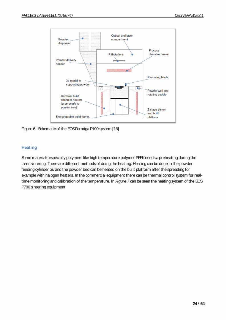
Figure 6. Schematic of the EOS Formiga P100 system [16]
Heating
Some materials especially polymers like high temperature polymer PEEK needs a preheating during the laser sintering. There are different methods of doing the heating. Heating can be done in the powder feeding cylinder or/and the powder bed can be heated on the built platform after the spreading for example with halogen heaters. In the commercial equipment there can be thermal control system for real-time monitoring and calibration of the temperature. In Figure 7 can be seen the heating system of the EOS P700 sintering equipment.
PROJECT LASER-CELL (278674) DELIVERABLE 3.1
25 / 64
Figure 7. Schematic of the EOS P700 system [16]
3. MATERIALS FOR SELECTIVE LASER SINTERING
One of the main advantages of SLS technology is the material versatility. Theoretically any material that is available as powder can be processed via laser sintering. [16]
In practice the commercial selection of laser sintering materials is quite narrow. Research work has been concentrated mostly to investigate commercially available materials and information about sintering of other materials is available quite little. [16]
Metals
Currently available alloys used in the process include 17-4 and 15-5 stainless steel, maraging steel, cobalt chromium, inconel 625 and 718, and titanium Ti6Alv4. Theoretically, almost any alloy metal can be used in this process once fully developed and validated. [12] EOSINT metal materials are presented in Table 2. [31]
Table 2. EOSINT M materials – Overview [31]
PROJECT LASER-CELL (278674) DELIVERABLE 3.1
26 / 64
More about typical applications and characteristics of Nickel –alloys in the Table 3.
Table 3. Nickel based superalloys.
There are other sources for commercial materials for laser sintering too - for example DuraForm® Laser Sintering (SLS) Materials (mainly plastics and composites).
Polymers
Most of the commercial sintering polymers are based on polyamides. Polyamide is resistant to most chemicals, and the material itself is uncritical with regard to environmental and health aspects. Commercially available is material variants for the special requirements of different applications. These
PROJECT LASER-CELL (278674) DELIVERABLE 3.1
27 / 64
materials can be distinguished, among other things, by the filling, for example with aluminium, glass or carbon fibre. Even most of the commercial sintering materials are based on polyamides some sintering polymers made of polystyrene, TPE or PEEK is available. [16], [17], [18], [21], [8]
Most of the published research, predominantly performed by universities and public sector institutes, has focused on polyamide based materials, as a single material or blended or reinforced with other materials or nanoparticles [16], [1] One reason for wide use of PA based powder is that material allows the production of functional prototypes with good surface quality and definition, good mechanical properties and thermal resistance. However some published work has been carried out on non-commercial materials and distinctly new polymers. [9], [16]
When processing polymers by laser sintering it is essential that polymers to be processed should have their melt temperature higher than the crystallization temperature so that crystallization can be delayed and reduced during the building process to allow layers to bond and forming homogenous microstructure and both the selected materials satisfy this particular criterion. [8]
For laser sintering of macro-sized parts, the optimum particle size in terms of processing ability is generally around 45–90 µm. Part density, surface quality and accuracy of the produced parts have all been found to increase with decreasing particle size; however, particles smaller than 45 µm can make spreading of the powder difficult due to static forces. [16] However, sintering of bigger particle size than 45–90 µm is possible. When bigger particle size is used their surfaces are rough and porous. Those materials could find use in applications where a smooth surface is not required or even desired. Figure 8 illustrates two materials, Polylactic acid (PLA) and HDPE, which have been processed using a particle size range of 150–200 µm and 425–600 µm respectively. [16]
Figure 8. Parts produced from PLA and porous HDPE using a large particle size. [16]
The size, size distribution and morphology of individual powder particles, along with the interactive nature of the particles with one another, influence their ability to flow. Ideally powders should have high sphericity to facilitate flow, reduce the surface area to volume ratio and improve packing efficiency. Various inorganic powdered additives, such as hydrated silicas, glassy oxides, fluoroplastics and metallic stearates, can be used to improve powder flow. The flow agent, typically 1 µm or less particle size, should be added in minimal quantity so as not to compromise the mechanical properties. [16] [2]
Humidity and electrostatic charge can affect the flow of polymer powder across the powder bed. Particles can become electrostatically charged during sieving and handling, influenced by crystalline defects, impurities, absorbed gas molecules, moisture, stress resulting from milling and temperature. Relative humidity can also affect flow and powders are often dried and monitored before processing. However, this again is material dependent property and these factors must be established for each material. [16]
PROJECT LASER-CELL (278674) DELIVERABLE 3.1
28 / 64
In this project the aim is to investigate the sintering of PEEK and Teflon. One noteworthy different between generally used polyamide and materials used in this project is the melting temperature. The melting temperature of PEEK and Teflon is approximately 150 C higher than PA.
Some research about laser sintering of PEEK can be found from literature [2], [ 3]. Laser sintering of Teflon is quite new challenge but other sintering method of Teflon like sintering on oven has been done [22].
4. PARAMETERS FOR LASER SINTERING PROCESS
There are many parameters which affects to the laser sintering. Those parameters are laser and other process parameters, powder feed and heating parameters and material properties/parameters.
Process parameters
Sintering or bonding between particles during SLS occurs by raising the temperature of the powder above the softening or melting temperature by a laser beam heat source. Similar to other laser assisted material processing techniques, success of SLS depends strongly on adequate absorption or coupling of the laser energy. Laser and other process parameters effects to the laser energy and have a big role in laser sintering. Most of these parameters (Table 4) have the same influence on SLS processed metal parts as they do on polymer parts. However, surface tension and viscosity have a somewhat more significant role in determining successful processing of metals by direct SLS. [15] Parameters affects to the laser energy are laser power, the laser spot diameter, the scan velocity and the scan spacing. Of course all the laser energy does not turn to the heat because of material absorption properties and heat convention (Figure 9). [2, 8]
Table 4. Process parameters which affect sintering and densification of SLS-processed parts [15]
PROJECT LASER-CELL (278674) DELIVERABLE 3.1
29 / 64
Figure 9. The main energy terms in laser sintering [8].
Applied energy density at the surface of the powder bed is the most widely applied function for predicting the response of the SLS process. Energy density can be calculated from equation:
Where P is laser power, BS is beam speed, SCSP is scan spacing and f is a constant involving the beam spot size. Equation (2) can be used to approximately calculate the laser power required for a given material depending on its thermal properties [5]
Where is powder bed density, Db is diameter of laser beam, LT is layer thickness, C is specific heat, Tm is melting temperature, Tb is bed temperature, Lf is latent melting heat and R is reflectivity. From equations (1) and (2), it can be seen that the main fabrication parameters with regard to energy delivered that influence the SLS process are P, BS, SCSP and LT. [5]
PROJECT LASER-CELL (278674) DELIVERABLE 3.1
30 / 64
The effect of energy density to the sintering results has been widely investigated, for example the effect of energy density to the width and depth of the sintered line for polyamide powder can be seen in Figure 10 , Figure 11 and Figure 12. In the sintering tests of PA was noticed that higher the energy and lower the porosity, higher the shrinkage and higher mechanical properties might be achieved. [8]
Figure 10 . Experimental analysis on polyamide powder: width and depth as a function of energy density [8]
Figure 11. Main dimensions of the profile of sintered lines (width and depth) as a function of the Energy Density adopted [11]
PROJECT LASER-CELL (278674) DELIVERABLE 3.1
31 / 64
Figure 12. Laser sintered PA12 part. [11]
It has been noticed for polyamide materials that SLS specimens made with a quite reduced value of energy density (of the order of 0.08 J/mm2) have relatively higher dimensional accuracy. [11]
The effect of energy density is examined also with SiC/polyamide composites and it seems to have a crucial effect on strength as given in Figure 13 which showed that the maximum strength was obtained at 0.04 J/mm2. Below this level, the incident energy was insufficient, resulting in partial melting of polyamide and structural porosity. Above 0.04 J/mm2, the energy was too great causing degradation of the polyamide, increased porosity and reduction in part strength. [5]
Figure 13. Effect of laser energy density on weight % SiC/polyamide composite parts [5]
One important parameter that effects to the laser energy is the laser scanning speed and laser power. The effect of those parameters was investigated by sintering of bronze-nickel powder. The density of the SLS bronze-nickel parts increased as the scan speed decreased. Also, the density was found to increase with increasing laser power, at a constant scan speed ( Figure 14). Higher density is achieved with slower scan speed and higher laser power due to an increased amount of energy input to the powder surface. A higher
PROJECT LASER-CELL (278674) DELIVERABLE 3.1
32 / 64
amount of energy to the powder bed increases the temperature locally to result in a large amount of liquid phase formation. [15]
Figure 14. Fractional density of SLS-processed bronze-nickel parts as a function of scan speed and laser power [15]
The effect of laser power and scanning speed to the strength of the material, which is primarily a function of fractional density (or porosity), have been also investigated. When sintering bronze-nickel powder strength, exhibited a similar trend as density with respect to scan speed and laser power (Figure 15). Pores reduce the effective load carrying capacity of a material and act as stress concentrators and effective crack initiation sites. Therefore, a sample with residual porosity would be expected to be weaker than a fully dense bulk material. In addition to fractional density, the strength of such porous compacts depends on various powder characteristics such as particle size, particle size distribution and particle shape. [15]
PROJECT LASER-CELL (278674) DELIVERABLE 3.1
33 / 64
Figure 15. Ultimate tensile strength of SLS-processed bronze-nickel parts as a function of scan speed and laser power. [15]
Energy per unit area, by varying the laser power has also been investigated with polymer materials and it is known to have a very decisive influence on the sintering results. In these tests (Figure 16 and Table 5) the results were analysed by measuring the sintering thickness was measured. Sintering of PEEK, black discolouration is a sign for a change in oxygen to carbon ratio. [3]
Figure 16 . Position of measurement spots on sample and distribution of samples in building zone (diameter 210 mm) [3]
PROJECT LASER-CELL (278674) DELIVERABLE 3.1
34 / 64
Table 5 . “Bad” and “good” values for Paired Comparison [3]
The effect of the laser power to sintering results has been also investigated with SiC/Polyamide matrix composites. It was noticed that by increasing the laser power from low to high level, the porosity of the built part decreases and this would be expected to cause an increase in part strength. The change in porosity is due once again to the greater amount of energy being delivered to the powder bed, resulting in increased melting of the polymer material and therefore a reduction in porosity occurs. [5]
Besides the scanning speed and laser power, the scan spacing is a parameter, which affects to the energy and heat input. The effect of hatch spacing to the density of sintered component was investigated with polymer material PEEK (Figure 17).
Figure 17. Diagram shows relative density versus area energy for variation of hatch distance and laser power [2]
Sintering can occur between solid particles by formation of a neck between individual particles due to diffusion of atoms along the surface, grain boundaries or other paths at elevated temperature. Such solid state sintering is rather slow and requires an extremely long time (hours) for completion. [15]
A more rapid form of sintering is liquid phase sintering, in which a component of the material system is in liquid phase during the sintering process. Presence of the liquid phase results in rapid sintering since mass transport can occur by liquid flow and particle rearrangement. During SLS, the entire thermal cycle occurs locally very quickly, so rapid sintering is necessary. [15]
PROJECT LASER-CELL (278674) DELIVERABLE 3.1
35 / 64
The duration of the laser beam on any powder particle is short, typically between 0.5 and 25 ms. Therefore, bonding or sintering must occur speedily, in the order of seconds. This is achieved by viscous flow or by melting. Polymers above the softening point have a strong temperature dependent viscosity and are suitable for SLS processing. Metals do not have a softening phenomenon but rather have a generally much higher melting temperature. Therefore, a melting-solidification approach is used for SLS processing of metals. [15]
Early attempts to process single phase metals with congruent melting points were unsuccessful, and an approach in which only partial melting is achieved was employed. For these reasons, SLS of metals, as we are presently practising it, is similar to liquid phase sintering in that both processes employ a material system which has a mix of high and low-melting materials such that the low melting phase melts while the high melting phase remains solid and is bonded together by the melt. [15]
Early attempts to SLS process metallic powders and powder blends of copper, lead, tin, and zinc proved to be unsuccessful because of balling (Figure 18). [15]
Figure 18. Micrographs of the surface and side of an SLS part [15]
PROJECT LASER-CELL (278674) DELIVERABLE 3.1
36 / 64
SLS studies on pre-alloyed single phase bronze powder in a controlled atmosphere at elevated temperature yielded much better results than previously obtained (Figure 19). [15]
Figure 19. Pictures with much better results [15]
The productivity of the sintering can be compared with volumetric productivity. The Volumetric Productivity (VP), obtained as the product of scanning speed by width and depth. For example for material Polyamide Dura FormTM was found to have highest VP 250 mm3/s. If the energy density is too high the productivity of the process is reduced. [11]
Layer thickness is one important factor which indicates the result of sintering. The typical layer thicknesses used in LS are 0.1 mm or 0.15 mm, equating to 2–3 times the average recommended particle size. Using
PROJECT LASER-CELL (278674) DELIVERABLE 3.1
37 / 64
this proportional figure ensures that the majority of particles receive direct contact from the laser, rather than relying on particle-to-particle conduction. Too thin a layer, e.g. using a layer thickness equivalent to just one times the average particle size, causes the particles to segregate during deposition. [16]
Preheating of polymer materials
For successful processing, polymer powders generally need to be heated whilst in the powder bed, both during the actual laser scanning process, and also for a sufficient length of time before the parts are built and after they have been completed. The laser is then simply used to tip the material over into its molten state. For semi-crystalline polymers, the pre-heat temperature is typically just below Tm; for amorphous polymers it is equal to or just below the Tg. The highest temperature that does not cause un-scanned powder to consolidate during the build is generally desired so as to minimise (a) the amount of energy required by the laser for consolidation, (b) the thermal gradient between the sintered and supporting powder, and (c) thermal expansion of the powder caused by the laser. In semi-crystalline polymers, preheating the powder minimises shrinkage that occurs during cooling and re-crystallisation. By controlling the rate of crystallisation, parts can be produced with improved dimensional accuracy and reduced risk of distortion.[16]
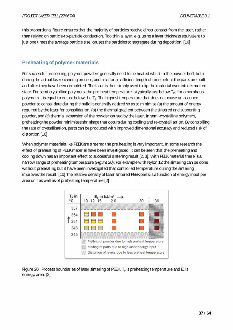
When polymer materials like PEEK are sintered the pre heating is very important. In some research the effect of preheating of PEEK material have been investigated. It can be seen that the preheating and cooling down has an important effect to successful sintering result [2, 3]. With PEEK material there is a narrow range of preheating temperature (Figure 20). For example with Nylon 12 the sintering can be done without preheating but it have been investigated that controlled temperature during the sintering improves the result. [10] The relative density of laser sintered PEEK parts is a function of energy input per area unit as well as of preheating temperature [2]
Figure 20. Process boundaries of laser sintering of PEEK. Tp is preheating temperature and Ea is energy/area. [2]
PROJECT LASER-CELL (278674) DELIVERABLE 3.1
38 / 64
Material parameters
The inherent versatility of SLS technology combined with a large variety of powder materials allows a broad range of advanced rapid prototyping and manufacturing applications. As a matter of fact, the powder consolidation mechanisms depend on the nature of the material used and on the mechanical properties to be obtained (e.g. porosity).
- Solid State Sintering is a consolidation process occurring below the material’s melting temperature and governs the agglomeration of most ceramic and metallic powders.
- Liquid Phase Sintering is common for mixture of two-component powder, composite powder particles and coated particles.
- Partial Melting can be adopted for metals and for polymers under the threshold value represented by the glass transition temperature.
- Full Melting is a third major consolidation mechanism often applied to metals to achieve fully dense parts.
- Chemical Induced Binding is also possible for polymers, metals and ceramics even though not commonly used in commercial applications. [11]
Metal and polymer are quite different materials so they have different properties which effect to the sintering. First the most important parameter is the absorption of different wavelengths.
Classical liquid phase sintering is divided into three overlapping stages. Considering the short thermal cycle of SLS, only the first stage of liquid phase sintering is expected to play a significant role in the sintering during SLS. In this stage, a liquid is formed between solid particles. Densification occurs as a result of the rearrangement of solid particles under the influence of capillary forces exerted on them by the wetting liquid. The capillary force exerted on the particles by the liquid, and the wetting of the solid particles by the liquid, determine the success of both liquid phase sintering and SLS. [15]
Table 6. Material properties which affect sintering and densification of SLS-processed parts [15]
PROJECT LASER-CELL (278674) DELIVERABLE 3.1
39 / 64
The wetting characteristics of the solid phase by the liquid phase are crucial in successful SLS processing. The wetting of a solid by a liquid is related to the surface tension of the solid-liquid, solid-vapour, and liquid-vapour interfaces. [15]
During SLS processing, the material is partially molten. Bonding of solid particles by the molten liquid depends on the wetting characteristics. When choosing material systems for SLS processing, it must be ensured that the surface tension of the liquid phase is lower than that of the solid phase. This can be accomplished by choosing the right binary material systems, including trace alloying of the low melting point material, or by varying the processing conditions such as processing temperatures and atmosphere. [15]
Wetting properties can also be improved by using fluxing agents or in situ deoxidizers. These additives are added in small quantities to the powder mix to aid sintering by lowering the wetting angle between liquid phase and solid phase. Although direct evidence of wetting characteristics on SLS has not been studied, from qualitative studies on SLS for several materials, it can be concluded that fluxing agents or in situ deoxidizers are effective in influencing the wetting characteristics and thus aid in SLS processing. [15]
In addition to favourable conditions for wetting, it is also necessary for the viscosity of the molten liquid to be low enough such that it successfully surrounds the solid particles. The rheological properties of the molten liquid in conjunction with solid particles play an important role in determining successful SLS processing. [15]
Experimentally with Ti powder, it transpires that heat conductivity in the contact point between particles increases during surface melting and formation of the contact neck. This is evident from increasing of heat penetration area diameter. [6]
Polymers
Thermo-physical properties of polymers, such as density, specific heat, thermal conductivity, diffusivity, glass transition and melting temperature represent key parameters in the SLS of polymer powders. Other properties of polymer powder, such as granulometry and average grain dimension are also important. [8, 11]
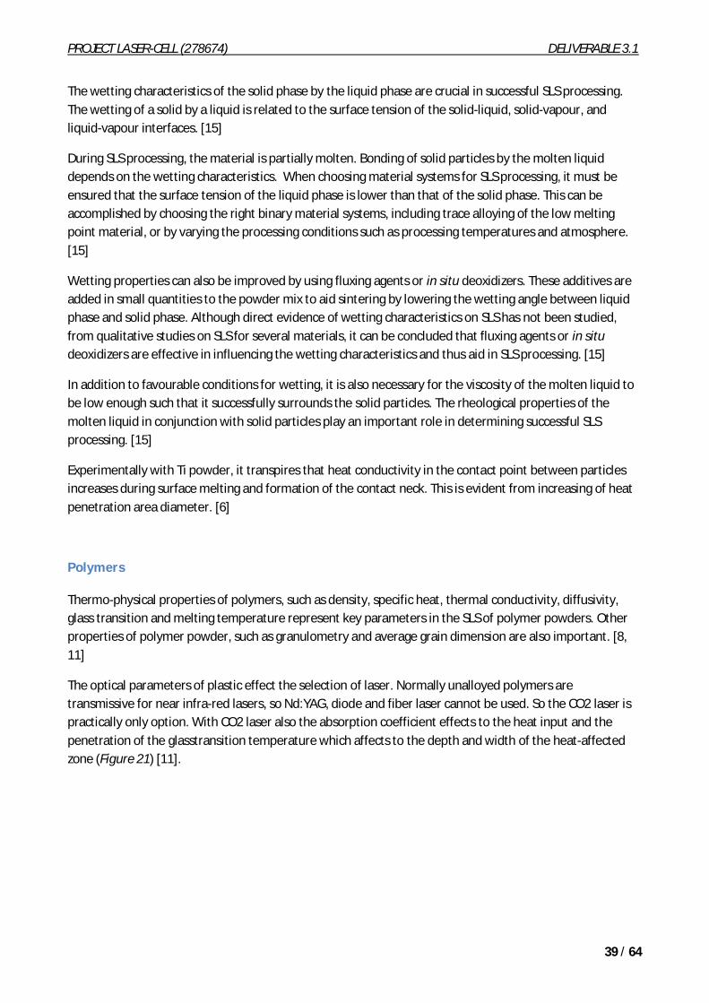
The optical parameters of plastic effect the selection of laser. Normally unalloyed polymers are transmissive for near infra-red lasers, so Nd:YAG, diode and fiber laser cannot be used. So the CO2 laser is practically only option. With CO2 laser also the absorption coefficient effects to the heat input and the penetration of the glasstransition temperature which affects to the depth and width of the heat-affected zone (Figure 21) [11].
PROJECT LASER-CELL (278674) DELIVERABLE 3.1
40 / 64
Figure 21. The main energy tems in SLS [11].
With polymer based powders, thermal sintering occurs already at a temperature lower than the melting point: at the glass transition temperature, agglomeration among grains is dominated by polymer chain rearrangement and cross-linking. [8, 11]
5. APPLICATIONS AND CASE STUDIES
Following case studies do have some minor similarities with our case in the Laser-Cell project.
Example of laser sintering of Nickel alloy
Loose single-component Ni-alloy powder (15-17 per cent Cr; 3-4 per cent B; 4 per cent Si; 0.6-0.8 per cent C) with a spherical shape was used in a study carried out by Nikolay K. Tolochko et al. at the National Academy of Sciences at Belarus [14]. The particle sizes range from 100 to 200 µm. The Ni-alloy powder was resistant to oxidation at high temperature, allowing a processing without a protective gaseous atmosphere. [14]
A comparison of selective laser sintering (SLS) and selective laser cladding (SLC) methods was realized. The powder feeding system formed the flow of powder particles directed into the zone of laser spot. The particles were deposited directly onto a substrate or onto the top of a pedestal. [14]
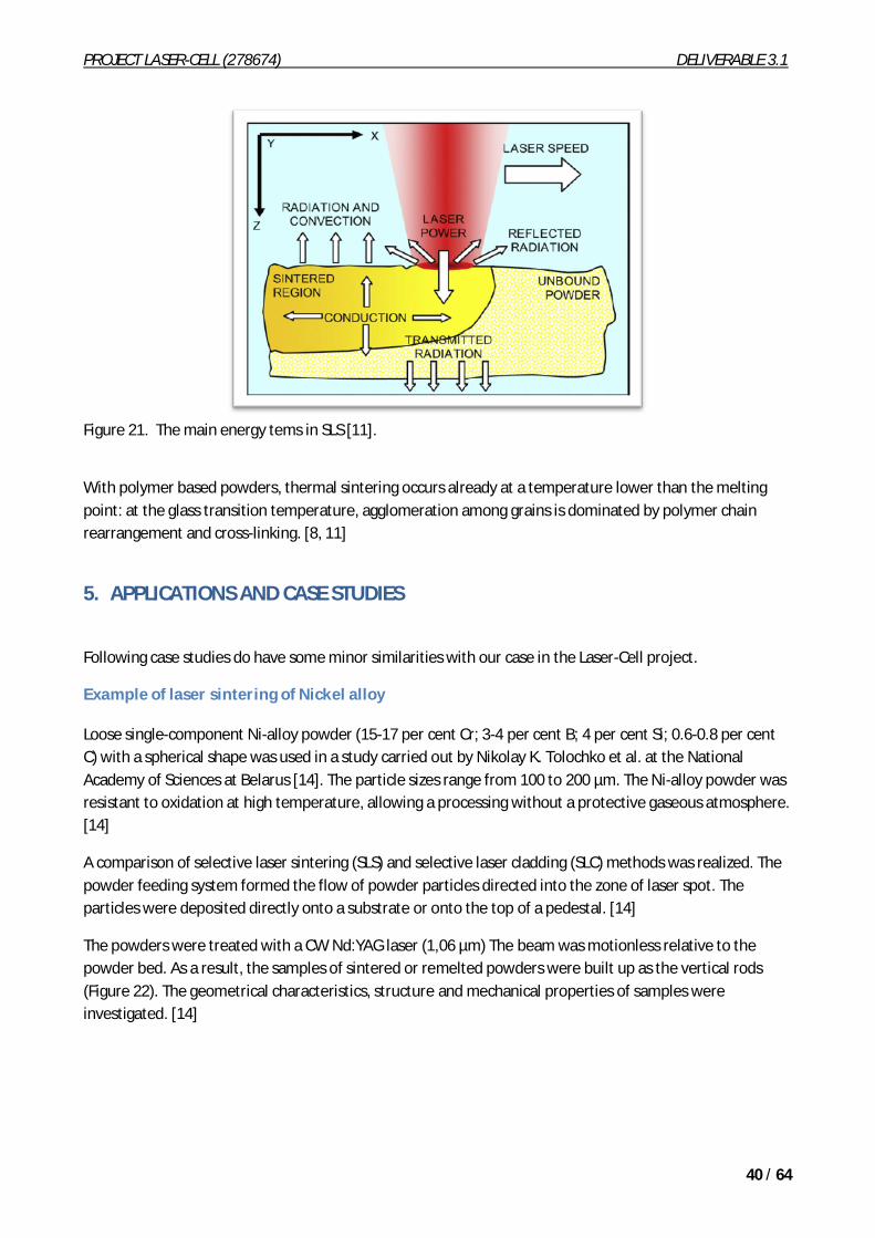
The powders were treated with a CW Nd:YAG laser (1,06 µm) The beam was motionless relative to the powder bed. As a result, the samples of sintered or remelted powders were built up as the vertical rods (Figure 22). The geometrical characteristics, structure and mechanical properties of samples were investigated. [14]
PROJECT LASER-CELL (278674) DELIVERABLE 3.1
41 / 64
Figure 22. Samples obtained in experiments [14]
Usually, powder feeding systems such as a scraper blade, a rolling cylinder or a slot feeder are used in conventional SLS. All these systems form extended powder layers as a result of a layer-by-layer deposition of powder on the substrate. As a consequence, during laser processing the part had contacts with surrounding powder particles which were not subjected to the direct laser influence. On the other hand, the powder feeding systems used in conventional SLC form a flow of powder particles directed into the zone of laser spot by means of a carrier gas. As a consequence, there is no contact between the part built and any surrounding powder. [14]
The beam was directed to the centre of the substrate or to the top of the pedestal. As a result, rods were formed on the substrate or on the pedestal. In the first case the rod during its building was in contact with the surrounding non-sintered powder. In the second case, the rod was free standing in the air. In general, the powder was subjected to a collimated laser beam. In the case of the formation of rods on the substrate by SLC, a focused beam was used to increase the radiation power density Q. [14]
PROJECT LASER-CELL (278674) DELIVERABLE 3.1
42 / 64
Figure 23. Schematic diagram of powder feeding system
The microstructure of the rods obtained by SLS was a sintered structure with high porosity. The rods obtained due to SLC were characterized by a solidification structure with lower porosity. [14]
Table 7. Porosity and pores’ sizes for different types of sample zones
PROJECT LASER-CELL (278674) DELIVERABLE 3.1
43 / 64
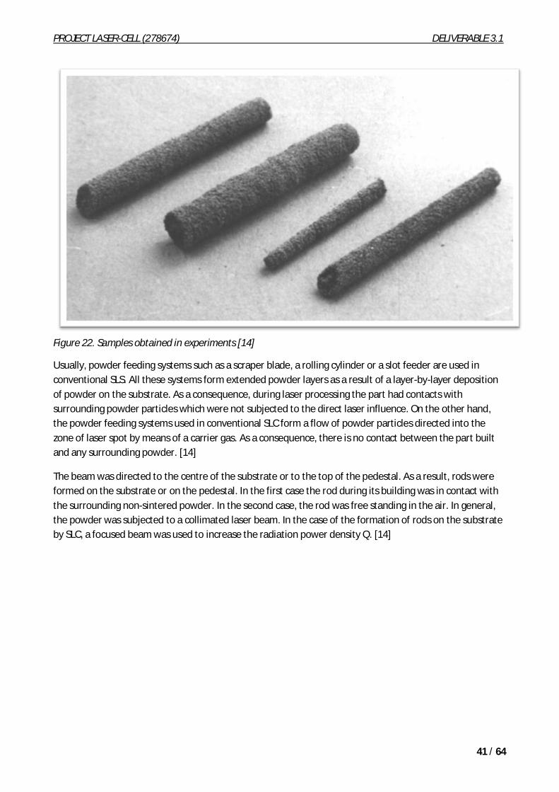
Figure 24. Cross sections of the specimens.
PROJECT LASER-CELL (278674) DELIVERABLE 3.1
44 / 64
The bend strength s of the samples depends on their structure. The value of s increases with the density of the samples, which increases with the radiation power density Q.
Figure 25. Bend strength s of rods as a function of radiation power density Q.
Parameters of both the laser radiation and the powder flow are important. Their values can influence the geometry, structure and mechanical properties of the samples. It is interesting to note that the methods of laser processing considered are similar to the well-known Verneuil method of crystal growth in physical and technological principals.
Fabrication of modified graphite bipolar plates
The purpose of the study was to produce electrically conductive, fluid impermeable graphite bipolar plates for a direct methanol fuel cell, using indirect selective laser sintering (SLS) and suitable post processing techniques. Bipolar plates were made by the indirect SLS of graphite powder and phenolic resin mixture. The phenolic resin binder was then burnt off at a high temperature in a vacuum furnace to produce a 100
PROJECT LASER-CELL (278674) DELIVERABLE 3.1
45 / 64
per cent carbon part. This brown part was then infiltrated using a low-viscosity cyanoacrylate to seal up the open pores, rendering the plates fluid impermeable. [34]
Figure 26. (a) Schematic representation of DMFC working principle; (b) exploded view of a DMFC stack.
The process of producing bipolar plates by indirect SLS as shown in Figure , involves the production of a green part by the indirect SLS of a mixture of graphite (GS-150E, Graftech, Inc.) and phenolic (GP-5546, Georgia Pacific) powders in a 70-30 wt% ratio, in a Sinterstation 2000 (Chen, 2006). The porous green part is then heated in a vacuum furnace to carbonize the phenolic binder, thus producing a “brown” part. Phenolic is a “high ash” polymer, producing significant residual carbon after thermal dissociation. This carbon is effectively a high-temperature binder of the graphite powder. [34]
Figure 27. Flow chart of the experimental process of bipolar plate production by indirect SLS [34]
Post processing of this brown part includes infiltration with low-viscosity cyanoacrylate glue that seals the pores, thereby making the part fluid impermeable, and polishing of the surfaces to expose the underlying electrically conductive graphite matrix. The parameters used for the SLS process are: fill laser power (10-20 W), outline laser power (4 W), powder layer thickness (0.1016 mm), laser scan spacing (0.0762 mm), laser scan speed (1.524 m/s). [34]
PROJECT LASER-CELL (278674) DELIVERABLE 3.1
46 / 64
Figure 28. (a) Exterior surface of porous graphite specimen before deposition of electro-polymerised polyaniline; (b) after deposition lack of interior deposition of polyaniline on porous graphite specimen at; (c) 50 x magnification; (d) 430 x magnification [34]
Table 8. Porosity measurements of SLSed graphite-phenolic parts, before and after phenolic pyrolysation[34]
A process to make bipolar plates that are fluid impermeable and which possess acceptable electrical conductivity has been demonstrated. It has been shown that low-viscosity ethyl cyanoacrylate polymer infiltrates the specimen completely under vacuum, producing a fully dense part whose electrical conductivity is maintained by grinding the surface to remove the cyanoacrylate. The electrical conductivity of the porous graphite matrix was observed as a function of the burnout temperature, and high values of
PROJECT LASER-CELL (278674) DELIVERABLE 3.1
47 / 64
conductivity (> 200 S/cm) have been achieved by varying burnout temperature. Research into the change in materials properties (morphology, electrical conductivity and pore structure) of the phenolic resin is underway to better understand the results observed. Future work also includes the production of bipolar plates based on computational fluid dynamics models aimed at improving fuel distribution across the electrodes and reduction of methanol crossover which is a critical issue in DMFCs. [34]
Critical considerations for LS graphite bipolar plates are the strength of the parts in the green, brown and finished states as well as the final part electrical conductivity. US Department of Energy target values for bipolar plate flexural strength and conductivity are 4.1 MPa and 100 S/cm, respectively. LS finished bipolar plates possess flexural strength in the range of 12–40 MPa, but green parts are particularly weak, 1–2 MPa, which complicates handling during processing. Electrical conductivity of LS bipolar plates is 200–400 S/cm. [35]
Carbon fiber (CF) additions are known to improve the strength and conductivity of polymer matrices. The effect of 0-26 volume percent chopped carbon fiber (CF) on strength and electrical conductivity of LS graphite bipolar plates was evaluated. Fiber additions improved the green and brown strength significantly. Finished part flexural strength increased from 35 MPa to almost 50 MPa with CF additions. The electrical conductivity of finished parts was lowered by CF additions. [35]
Laser sintering of carbon nanotube-reinforced ceramic nanocomposites
The fabrication of carbon nanotube (CNT)-reinforced ceramic nanocomposites through laser sintering has been rarely studied, and the fabrication feasibility has been rarely tested. Laser sintering is a flexible, localized and high-precision process, which can also potentially produce coatings or parts with complicated shapes and/or spatially controlled compositions. Therefore, compared with other technologies laser sintering has its own advantages. [36}
Experimental investigations reported in this paper have confirmed the feasibility of fabricating CNT-reinforced ceramic nanocomposites through laser sintering of ceramic nanoparticles and CNTs. The studies show that laser sintering can induce the agglomeration of ceramic nanoparticles into a relatively more continuous ceramic phase, and during the sintering process CNTs are well preserved without any obvious quality degradation, and they are also bonded with the ceramic phase after laser sintering. [36]
Figure shows a schematic diagram of the nanocomposite fabrication process, which consists of two steps: (i) paper-making to realize a good dispersion of CNTs in ceramic nanoparticles (the produced paper will be called carbon nanotube paper (CNTP)), and (ii) laser sintering of CNTP to produce the composites. The paper-making process involves four stages: (1) dispersing CNTs into water using high energy sonication; (2) dispersing ceramic nanoparticles into water by sonication; (3) mixing the two solutions together to create a uniform suspension of CNTs and ceramic nanoparticles; and (4) infiltrating the suspension through a filter paper to make a hybrid CNT/ceramic nanoparticle paper (called CNTP for simplicity). The paper-making process can realize a good dispersion of the CNTs with a controlled concentration in the composite paper. In this study, TiO2 ceramic nanoparticles with an average size of around 300 nm were used in the papermaking process. Multi-walled carbon nanotubes (MWCNTs) were received from Nanolab,
Inc. (length: 5–20 m) and used as received. [36]
PROJECT LASER-CELL (278674) DELIVERABLE 3.1
48 / 64
Figure 29. Schematic diagram of the ceramic nanocomposite fabrication process: (a) the paper-making process to produce the carbon nanotube paper (CNTP), which consists of ceramic nanoparticles and well dispersed carbon nanotubes; (b) laser sintering of CNTP to fabricate the CNT-reinforced ceramic nanocomposites. [36]
Laser sintering of the CNTP was performed using a SPI G3.0 laser system, which can be operated in both the continuous mode and the pulsed mode with adjustable pulse durations. In this study, it was operated in a mode with full pulse duration of 200 ns. The laser beam has a wavelength of 1064 nm. It is delivered and focused through a laser scan head (ScanLab, HurryScan 14) onto the surface of the CNTP that is positioned by three linear motion stages (Newport ILS 100PP) in X, Y and Z directions. The scan head has a lens with a 100 mm focal length, and the focused laser beam has a spot diameter of 30 m on the CNTP surface. To avoid chemical reactions with the ambient air, argon gas was applied to protect the CNTP surface during laser sintering. [36]
The experimental characterizations combining SEM, TEM, EDS and Raman spectroscopy techniques show that: (1) the laser sintering process has induced the agglomeration of ceramic nanoparticles into relatively more continuous ceramic phase; (2) CNTs have been well preserved during the sintering process without any obvious quality degradation or relative mass loss (as compared to the ceramic phase); (3) CNTs are bonded with the ceramic phase after laser sintering. Therefore, the study has confirmed the feasibility of fabricating CNT-reinforced ceramic nanocomposites through laser sintering. It would be good in the future to fundamentally understand the laser sintering mechanisms and the CNT-ceramic bonding nature, optimize the process conditions and test/improve the mechanical properties of the sintered nanocomposite. [36]
Porous biocompatible implants and tissue scaffolds synthesized by selectivelaser sintering
An investigation of the technical aspects of producing sufficiently high strength porous biocompatible medical implants and tissue scaffolds from nitinol or pure titanium using selective laser sintering/melting (SLS/M) was presented. [37]
PROJECT LASER-CELL (278674) DELIVERABLE 3.1
49 / 64
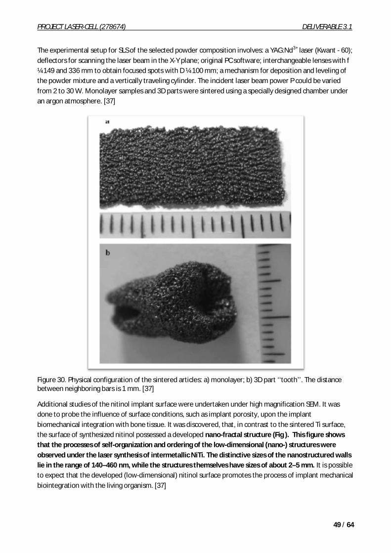
The experimental setup for SLS of the selected powder composition involves: a YAG:Nd3+ laser (Kwant - 60); deflectors for scanning the laser beam in the X-Y plane; original PC software; interchangeable lenses with f ¼ 149 and 336 mm to obtain focused spots with D ¼ 100 mm; a mechanism for deposition and leveling of the powder mixture and a vertically traveling cylinder. The incident laser beam power P could be varied from 2 to 30 W. Monolayer samples and 3D parts were sintered using a specially designed chamber under an argon atmosphere. [37]
Figure 30. Physical configuration of the sintered articles: a) monolayer; b) 3D part ‘‘tooth’’. The distance between neighboring bars is 1 mm. [37]
Additional studies of the nitinol implant surface were undertaken under high magnification SEM. It was done to probe the influence of surface conditions, such as implant porosity, upon the implant biomechanical integration with bone tissue. It was discovered, that, in contrast to the sintered Ti surface, the surface of synthesized nitinol possessed a developed nano-fractal structure (Fig ). This figure shows that the processes of self-organization and ordering of the low-dimensional (nano-) structures were observed under the laser synthesis of intermetallic NiTi. The distinctive sizes of the nanostructured walls lie in the range of 140–460 nm, while the structures themselves have sizes of about 2–5 mm. It is possible to expect that the developed (low-dimensional) nitinol surface promotes the process of implant mechanical biointegration with the living organism. [37]
PROJECT LASER-CELL (278674) DELIVERABLE 3.1
50 / 64
Figure 31. Nanostructure formed after SLS + SHS in the Ni-Ti mixture. [37]
This work has confirmed that three-dimensional NiTi parts can be produced from Ti and Ni powders by using laser control synthesis with a laser energy input of 100–300 J/cm2. It shows that SLS–SHS processes have some advantages over the conventional routes including higher level of control of composition and homogeneity, pore formation as well as the possibility of a near net-shape processing. In addition, the reaction synthesis process using nitinol has some advantages due to the rapid cycle and high temperatures achieved. [37]
Manufacturing of fine-structured 3D porous filter elements by selective lasermelting
Experiments were carried out on SLM machine PM 100 (Phenix Systems) and SLS experimental equipment on the basis of a YAG:Nd3+ laser. PM 100 machine has the typical for SLM equipment design, with 100 mm-diameter manufacturing volume and up to 100 mm workpiece height. Operational temperature of the internal chamber is up to 900 C; this allows manufacturing parts not only from metal powders but also from ceramics. The source of radiation is YLR-50 CW Ytterbium fiber laser manufactured by IPG Photonics with P = 50W maximum power, l = 1075 nm wavelength and d =70 µm laser spot size. For the given laser parameters, the optimum thickness of the powder layer spread by a roller is 20–60 mm. Thicker layers are not desirable, as it leads to formation of droplets and, thus, to considerable deterioration of product
PROJECT LASER-CELL (278674) DELIVERABLE 3.1
51 / 64
quality. After laser scanning of each layer, the manufacturing plate is lowered by the thickness of the layer to be deposited, thus keeping the surface in the focal plane. [38]
Experimental equipment based on the YAG:Nd3+ CW laser with the wavelength 1060 nm and the laser spot size 50 and 100 mm (optical system with the focal length 149 and 336 mm) provides scanning areas of 50 mm x 50 mm and 100 mm x 100 mm, respectively. Laser power was up to 30W. [38]
In the present experiments stainless steel (grades 316L and 904L), Inconel 625 powders and metal–polymer powder compositions (polycarbonate and nickel alloys with composition ratio 1:6, 1:10–22) were employed. The particle size distribution (PSD) was analyzed by a granulo-morphometer ALPAGA 500NANO (OCCHIO s.a.).
Figure 32. Filter from stainless steel grade 316L with micro-sized square channels. Size of the channel is 150 mm x 150 mm, the wall thickness is 120 mm. [38]
Ways of optimization of SLS/SLM technology were considered and assessed through fabrication and characterization of small sized porous objects as filter elements. The influence of the major parameters such as scanning speed, laser power, distance between individual sintered lines and number of the sintered layers was studied. Different strategies of manufacturing thin-walled and functionally graded objects were analyzed. Optimal SLM parameters to produce fine walls with a minimum regular gap between them in order to obtain a narrow wall-pattern with an open pore structure were established. The possibility of manufacturing complex filters directly from CAD data with customized orientation and size of the channels from stainless steels and nickel alloys was studied. Porous functionally graded objects were sintered from a metal–polymer mixture. Influence of the operational parameters on the air permeability of the filter in oil and oil + water media was investigated. The obtained results could be successfully implemented in the manufacture of functional prototypes in chemical and biomedical applications. SLM technology shows considerable progress and makes it now possible to meet the trend for fabrication of complex shape objects with porous or lattice-type inner structure. [38]
Sintering PCL powder to fabricate highly porous scaffold for application incardiac tissue engineering
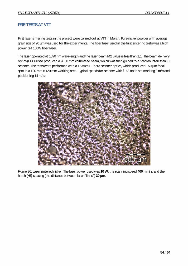
Polycaprolactone (PCL) powder (CAPA 6501, Solvay Interox Pte Ltd., UK) was used as the scaffold material. The melting temperature of the material is 58–60 C. PCL density was measured as 1.15 g cm3 using a mercury porosimeter (AutoPore IV 9500, Micromeritics Instrument Corporation). [7]
The scaffold was fabricated using SLS (Sinterstation 2500). The PCL powder used was relatively uniform, with average size of 100 µm. It was sintered at the following optimized parameters: part bed temperature of 40 C, laser power of 3W and scanning speed of 150 in/s. The sintering pattern on the machine was programmed to follow the design of the scaffold. [7]
PROJECT LASER-CELL (278674) DELIVERABLE 3.1
53 / 64
Sintering of PCL powder at the optimized parameters resulted in a typical sample characteristic of 48% porosity with a surface roughness of 33.7 µm. The tensile stiffness of a sintered rectangular PCL strut was measured as 0.43 ± 0.15 MPa and the tensile yield strength was 2.62 ± 0.96 MPa. The elongation at break of a sintered strut was approximately 89%, showing the high toughness of the sintered strut. [7]
Figure 34. Morphology of PCL particles sintered at 3 W Laser power and in 150 in/s scanning speed. (a) SEM at 35x magnification; (b) SEM at 100x magnification; (c) the macrostructure of the sintered scaffold. [7]
Figure 35. Empirical formula of compressive stiffness as a function of scaffold porosity [7]
PROJECT LASER-CELL (278674) DELIVERABLE 3.1
54 / 64
PRE-TESTS AT VTT
First laser sintering tests in the project were carried out at VTT in March. Pure nickel powder with average grain size of 20 µm was used for the experiments. The fiber laser used in the first sintering tests was a high power SPI 100W fiber laser.
The laser operated at 1090 nm wavelength and the laser beam M2 value is less than 1,1. The beam delivery optics (BDO) used produced a 6,0 mm collimated beam, which was then guided to a Scanlab Intelliscan10 scanner. The tests were performed with a 163mm F-Theta scanner optics, which produced ~50 µm focal spot in a 120 mm x 120 mm working area. Typical speeds for scanner with f163 optic are marking 3 m/s and positioning 14 m/s.
Figure 36. Laser sintered nickel. The laser power used was 10 W, the scanning speed 400 mm/s, and the hatch (HS) spacing (the distance between laser “lines”) 30 µm.
PROJECT LASER-CELL (278674) DELIVERABLE 3.1
55 / 64
Figure 37. Typical laser scan pattern.
Figure 38. Laser sintered nickel. The laser power used was 20 W, the scanning speed 400 mm/s, and the hatch (HS) spacing (the distance between “laser lines”) 30 µm.
PROJECT LASER-CELL (278674) DELIVERABLE 3.1
56 / 64
Figure 39. Laser sintered nickel. The laser power used was 25 W, the scanning speed 400 mm/s, and the hatch (HS) spacing (the distance between ” aser lines”) 10 µm. The size of the specimen is 8 mm x 8 mm.
Figure 40. Laser sintered nickel. The laser power used was 25 W, the scanning speed 400 mm/s, and the hatch (HS) spacing (the distance between “laser lines”) 20 µm. The size of the specimen is 8 mm x 8 mm.
PROJECT LASER-CELL (278674) DELIVERABLE 3.1
57 / 64
Figure 41. Laser sintered nickel. The laser power used was 25 W, the scanning speed 400 mm/s, and the hatch (HS) spacing (the distance between “laser lines”) 30 µm. The size of the specimen is 8 mm x 8 mm.
Figure 42. Laser sintered nickel. The laser power used was 25 W, the scanning speed 400 mm/s, and the hatch (HS) spacing (the distance between “laser lines”) 40 µm. The size of the specimen is 8 mm x 8 mm.
PROJECT LASER-CELL (278674) DELIVERABLE 3.1
58 / 64
Figure 43. Laser sintered nickel. The laser power used was 30 W, the scanning speed 400 mm/s, and the hatch (HS) spacing (the distance between “laser lines”) 30 µm. The size of the specimen is 8 mm x 8 mm.
Figure 44. Laser sintered nickel. The laser power used was 35 W, the scanning speed 400 mm/s, and the hatch (HS) spacing (the distance between” laser lines”) 30 µm. The size of the specimen is 8 mm x 8 mm.
PROJECT LASER-CELL (278674) DELIVERABLE 3.1
59 / 64
Figure 45. Laser sintered nickel. The laser power used was 40 W, the scanning speed 400 mm/s, and the hatch (HS) spacing (the distance between “laser lines”) 30 µm. The size of the specimen is 8 mm x 8 mm.
Figure 46. Laser sintered nickel. The laser power used was 100 W, the scanning speed 1 m/s, and the hatch (HS) spacing (the distance between “laser lines”) 30 µm. The size of the specimen is 20 mm x 20 mm.
PROJECT LASER-CELL (278674) DELIVERABLE 3.1
60 / 64
Figure 47. Laser sintered nickel. The laser power used was 100 W, the scanning speed 1 m/s, and the hatch (HS) spacing (the distance between “laser lines”) 30 µm. The powder has been slightly compressed before sintering.
Figure 48. Laser sintered nickel. The laser power used was 10 W, the scanning speed 400 mm/s, and the hatch (HS) spacing (the distance between “laser lines”) 30 µm.
PROJECT LASER-CELL (278674) DELIVERABLE 3.1
61 / 64
Figure 49. Laser sintered nickel. The laser power used was 30 W, the scanning speed 400 mm/s, and the hatch (HS) spacing (the distance between “laser lines”) 30 µm.
Figure 50. Laser sintered nickel. The laser power used was 40 W, the scanning speed 400 mm/s, and the hatch (HS) spacing (the distance between “laser lines”) 30 µm.
Observations after these early trials may be that because of drop formation (balling) probably lower power density with thinner layers should be used in the next round to achieve smaller size porosity and a little bit stronger structure. Sintered sheet produce from one or two layers felt more or less fragile in the hands of researchers.
CONCLUSION, LASER SELECTION
There are a lot of activities in the area of laser sintering in the world both in industry and in the field of research. For example EOS has installed already more than 1000 system globally. However it’s not easy to find any similar cases with same materials and same kind of components we are looking for in the Laser-Cell project.
In general fiber and disk lasers are the choice at the moment for laser sintering of metals. They have only one major disadvantage, which is the poor absorption to polymers. For the same reason CO2 lasers are still used for laser sintering of plastics. The beam quality of CO2 lasers in not the best possible, but the price/watt is low and they are widely used and reliable industrial tools.
PROJECT LASER-CELL (278674) DELIVERABLE 3.1
62 / 64
Prices for cw fiber and cw CO2 lasers at the power level of 200 W together with a scanner are roughly around 30.000 – 50.000 euros, but it is important to notice that any machine or integrated industrial workstations around the laser costs 3 - 10 times the price of the laser itself.
REFERENCES
[1] Processing and properties of carbon black-filled electrically conductive Nylon-12 nanocomposites produced by selective laser sintering. Athreya, S.; Kalaitzidou, K.; Das, S. (G.W. Woodruff Sch. of Mech. Eng., Georgia Inst. of Technol., Atlanta, GA, USA) Source Solid Freeform Fabrication Proceedings, Aug. 2009, p. 538-46 of xi+877 pp., 13 refs. Published by: University of Texas at Austin, Austin, TX, USA Conference: Solid Freeform Fabrication, Austin, TX, USA, 3-5 Aug. 2009, 2010: 11608419 INSPEC.
[2] Selective Laser Sintering of PEEK M. Schmidt1 (3), D. Pohle, T. Rechtenwald - CIRP Annals - Manufacturing Technology Volume 56, Issue 1, 2007, Pages 205–208.
[3] Comparison between Laser Sintering of PEEK and PA using Design of Experiment Methods, Rechtenwald, T., Eßer, G., Schmidt, M., Pohle, D., 2005, Proceedings of the 3rd International WLT Conference on Lasers in Manufacturing (LIM 2005), 3:263-267.
[4] Rapid Manufacturing and Rapid Tooling with Layer Manufacturing (LM) Technologies, State of the Art and Future Perspectives, Levy, G.N., Schindel, R., Kruth, J.P., 2003, Annals of the CIRP,52/2:589-609.
[5] Selective Laser Sintering of SiC/Polyamide Composites, Hon, K.K.B., Gill, T.J., 2003, Annuals of the CIRP, 52/1:173-176.
[6] On-line temperature monitoring in selective laser sintering/melting Yu. Chivela, I. Smurov. Physics Procedia 5(2010) 515–521 LANE 2010.
[7] Porous polycaprolactone scaffold for cardiac tissue engineering fabricated by selective laser sintering W.Y. Yeong, N. Sudarmadji, H.Y. Yu, C.K. Chua, K.F. Leong, S.S. Venkatraman, Y.C.F. Boey, L.P. Tan, Acta Biomaterialia, Volume 6, Issue 6, June 2010, Pages 2028–2034.
[8] Characterization of laser energy consumption in sintering of polymer based powders Alessandro Franco, Luca Romoli, Journal of Materials Processing Technology 212 (2012) 917– 926.
[9] Characterization of an aluminum-filled polyamide powder for applications in selective laser sintering Alida Mazzoli, Giacomo Moriconi, Marco Giuseppe Pauri, Materials and Design 28 (2007) 993–1000.
[10] Degree of particle melt in Nylon-12 selective laser-sintered parts, Hadi Zarringhalam, Candice Majewski and Neil Hopkinson Rapid Prototyping Journal 15/2 (2009) 126–132 q Emerald Group Publishing Limited [ISSN 1355-2546] [DOI 10.1108/13552540910943423].
PROJECT LASER-CELL (278674) DELIVERABLE 3.1
63 / 64
[11] Experimental analysis of selective laser sintering of polyamide powders: an energy perspective, Alessandro Franco, Michele Lanzetta, Luca Romoli, Journal of Cleaner Production 18 (2010) 1722e1730.
[12] www.eos.info
[13] Johnson, J.A. (1996), “Evaluating processing conditions by optical microscopy”, ANTEC ’96, Conference Proceedings, Indianapolis, IN, USA, 5-10 May, Vol. 111, pp. 3318-23.
[14] Nikolay K. Tolochko, Sergei E. Mozzharov, Igor A. Yadroitsev, Tahar Laoui, Ludo Froyen, Victor I. Titov, Michail B. Ignatiev, (2004), “Selective laser sintering and cladding of single-component metal powders”, Rapid Prototyping. Journal, Vol. 10 Iss: 2 pp. 88 – 97.
[15] Direct selective laser sintering of metals. Mukesh Agarwala; David Bourell; Joseph Beaman; Harris Marcus; Joel Barlow Follow Rapid Prototyping Journal , Volume 1 (1): 11 Emerald Publishing – Mar 1, 1995.
[16] Laser sintering of polyamides and other polymers, R.D. Goodridge, C.J. Tuck, R.J.M. Hague, Progress in Materials Science 57 (2012) 229–267.
[26] DMLS – DEVELOPMENT HISTORY AND STATE OF THE ART. M. Shellabear, O. Nyrhilä, Presented at LANE 2004 conference, Erlangen, Germany, Sept. 21-24, 2004.
[27] www.eos.info EOS emphasizes its market and technology leading role in metal laser-sintering at the Industrie show 2012 in Paris. [A press release]
[28] www.eos.info EOSINT P 800. The first laser-sintering system world-wide processing high performance polymers. [A press release]
PROJECT LASER-CELL (278674) DELIVERABLE 3.1
64 / 64
[29] DMLS Teknologia – Materiaalia lisäävä valmistus. Lasertyö 25 vuotta –juhlaseminaari 8.6.2011 LUT Lappeenranta. Olli Nyrhilä EOS. [ppt]
[31] Nikolay Tolochko, Sregei Mozzharov, Tahar Laoui, Ludo Froyen, (2003),"Selective laser sintering of single and two-component metal powders", Rapid Prototyping Journal, Vol. 9 Iss: 2 pp. 68 – 78.
[32] Laser sintering (SLS) of hard metal powders for abrasion resistant coatings. K. Maeda, T.H.C. Childs. Journal of Materials Processing Technology 149, 2004, 609–615.
[33] Manufacturing of WC–Co moulds using SLS machine. S. Kumar. Journal of materials processing technology 209 (2009 ) 3840–3848.
[34] Fabrication of modified graphite bipolar plates by indirect selective laser sintering (SLS) for direct methanol fuel cells. Kaushik Alayavalli, and David L. Bourell. Rapid Prototyping Journal 16/4 (2010) 268–274.
[36] Laser sintering of carbon nanotube-reinforced ceramic nanocomposites. Yibo Gaoa, Fei Liangb, Gregory Freihoferb, Benxin Wua, Bharathi Mohanb, Seetha Raghavanb, Jihua Goub, Shuyou Lic, Brian Albeea and Sandra Whaley Bishnoia. International Journal of Smart and Nano Materials Vol. 2, No. 4, December 2011, 219–229.
[37] Porous biocompatible implants and tissue scaffolds synthesized by selective laser sintering from Ti and NiTi. I. V. Shishkovsky, L. T. Volova, M. V. Kuznetsov, Yu. G. Morozovc and I. P. Parkind. J. Mater. Chem., 2008, 18, 1309–1317.
[38] Manufacturing of fine-structured 3D porous filter elements by selective laser melting. I. Yadroitsev, I. Shishkovsky, P. Bertrand, I. Smurov. Applied Surface Science 255 (2009) 5523–5527.