17
1 Project Management Guide for Lessees At The Wyoming Integrated Test Center Last update: 9/12/2017

1
Project Management Guide for
Lessees
At The
Wyoming Integrated Test Center
Last update: 9/12/2017
2
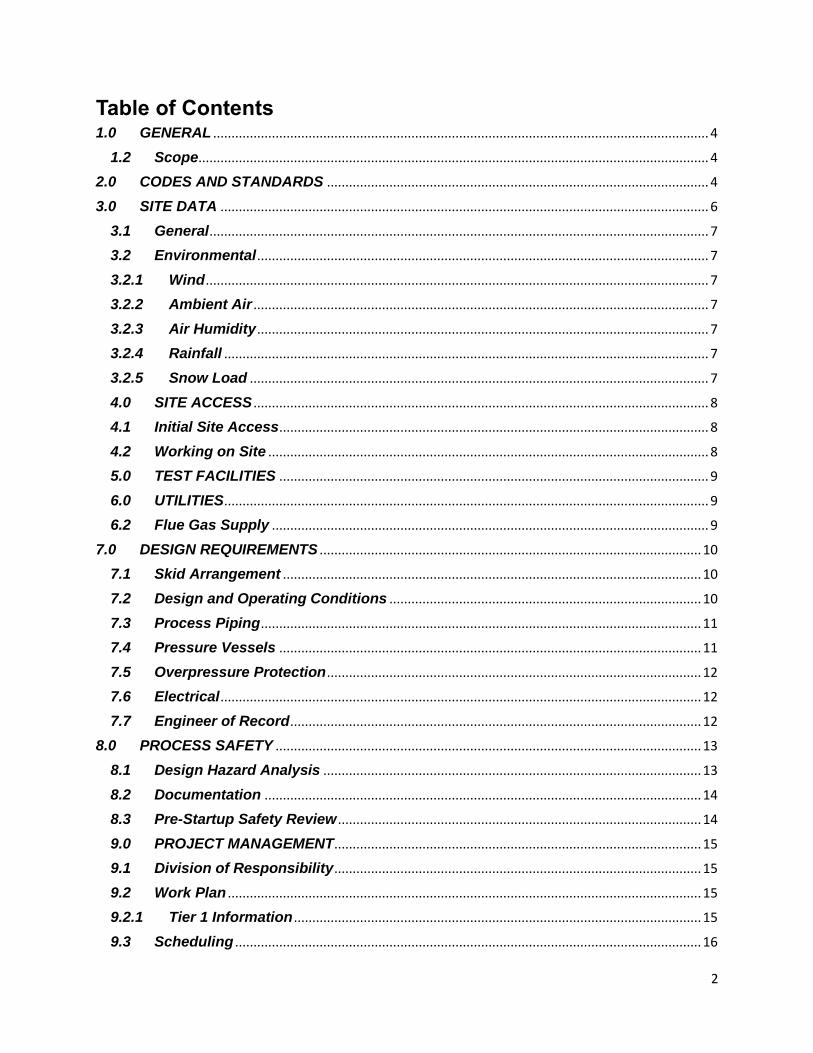
Table of Contents 1.0 GENERAL ....................................................................................................................................... 4
1.2 Scope........................................................................................................................................... 4
2.0 CODES AND STANDARDS ........................................................................................................ 4
3.0 SITE DATA ..................................................................................................................................... 6
3.1 General ........................................................................................................................................ 7
3.2 Environmental ........................................................................................................................... 7
3.2.1 Wind ......................................................................................................................................... 7
3.2.2 Ambient Air ............................................................................................................................ 7
3.2.3 Air Humidity ........................................................................................................................... 7
3.2.4 Rainfall .................................................................................................................................... 7
3.2.5 Snow Load ............................................................................................................................. 7
4.0 SITE ACCESS ............................................................................................................................ 8
4.1 Initial Site Access ..................................................................................................................... 8
4.2 Working on Site ........................................................................................................................ 8
5.0 TEST FACILITIES ..................................................................................................................... 9
6.0 UTILITIES .................................................................................................................................... 9
6.2 Flue Gas Supply ....................................................................................................................... 9
7.0 DESIGN REQUIREMENTS ........................................................................................................ 10
7.1 Skid Arrangement .................................................................................................................. 10
7.2 Design and Operating Conditions ..................................................................................... 10
7.3 Process Piping ........................................................................................................................ 11
7.4 Pressure Vessels ................................................................................................................... 11
7.5 Overpressure Protection ...................................................................................................... 12
7.6 Electrical ................................................................................................................................... 12
7.7 Engineer of Record ................................................................................................................ 12
8.0 PROCESS SAFETY .................................................................................................................... 13
8.1 Design Hazard Analysis ....................................................................................................... 13
8.2 Documentation ....................................................................................................................... 14
8.3 Pre-Startup Safety Review ................................................................................................... 14
9.0 PROJECT MANAGEMENT .................................................................................................... 15
9.1 Division of Responsibility .................................................................................................... 15
9.2 Work Plan ................................................................................................................................. 15
9.2.1 Tier 1 Information ............................................................................................................... 15
9.3 Scheduling ............................................................................................................................... 16
3
9.4 Data Requirements ................................................................................................................ 16
10.0 INSTALLATION/CONSTRUCTION ...................................................................................... 16
11.0 OPERATION ................................................................................................................................. 17
11.1 Operators ................................................................................................................................. 17
11.2 Control Systems ..................................................................................................................... 17
12.0 DISPOSITION OF MATERIALS ............................................................................................ 17
13.0 HOMELAND SECURITY ........................................................................................................ 17

4
1.0 GENERAL The Integrated Test Center (ITC) is a test facility located within the Basin Electric Dry Fork Power Station in Gillette WY. The operations of this facility are currently funded by the State of Wyoming, Tri-State Generation & Transmission, and the National Rural Electric Cooperatives Association. The facility specializes in the testing of technologies associated with post-combustion carbon capture. The ITC has the ability to test multiple third-party technologies simultaneously, 5MWe up to 18MWe of cleaned post combustion flue gas, around the clock, and for extended periods. The post-combustion test facility uses flue gas from a commercially dispatched base-loaded 422-MW coal-fired boiler located at Dry Fork Station, owned by Basin Electric Power Cooperative (Basin Electric) and Wyoming Power Agency (WMPA). Dry Fork Station is operated by Basin Electric Power Cooperative. It is the intent of everyone at the ITC to assist Lessees with the implementation of new technologies. Our primary goal is that project is successfully planned and executed in a manner to ensure the reliable and successful testing of new technologies on proposed: schedule and on budget, while maintaining the proper safety and quality standards. This document will serve as a guide to technology developers on best practices for projects installed at the ITC. It should be used in conjunction with the referenced codes and standards as a guide to assist lessees in understanding the available site resources, applicable design criteria, and safety procedures for the site.
1.2 Scope
This document governs the project criteria for any projects installed, tested, and decommissioned on site at the ITC. This guide should be used as an introductory information source for lessees. After review of this document, questions or clarifications should be referred to the Wyoming Infrastructure Authority (WIA).
2.0 CODES AND STANDARDS
The design and specification of all equipment furnished to the site shall be in accordance with applicable laws and regulations of the federal government and the state where the equipment is to be installed, including all local codes and ordinances. The following codes and standards are applicable to the various components within the scope of the specified equipment and materials. Applicable codes and standards from the following associations and organizations shall be used for design and construction:
AGA American Gas Association
ASCE American Society of Civil Engineers
ASCE 7-02 Minimum Design Loads for Buildings and Other Structures
ASME American Society of Mechanical Engineers
5
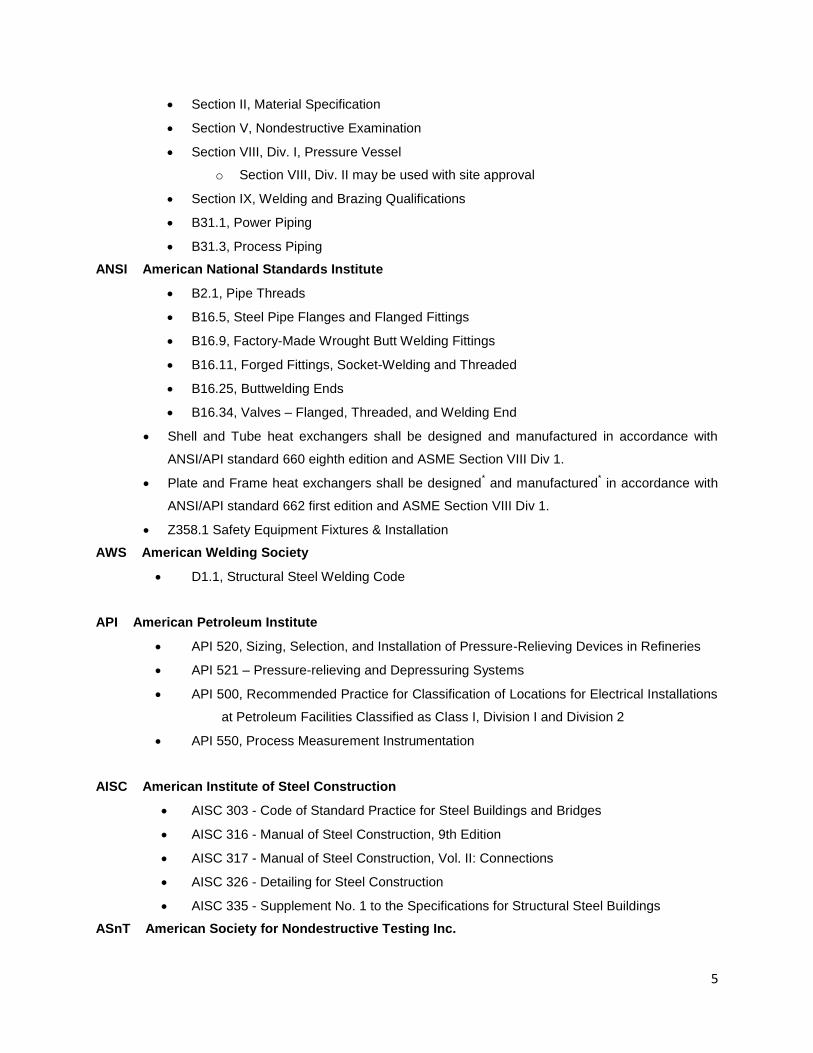
Section II, Material Specification
Section V, Nondestructive Examination
Section VIII, Div. I, Pressure Vessel
o Section VIII, Div. II may be used with site approval
Section IX, Welding and Brazing Qualifications
B31.1, Power Piping
B31.3, Process Piping
ANSI American National Standards Institute
B2.1, Pipe Threads
B16.5, Steel Pipe Flanges and Flanged Fittings
B16.9, Factory-Made Wrought Butt Welding Fittings
B16.11, Forged Fittings, Socket-Welding and Threaded
B16.25, Buttwelding Ends
B16.34, Valves – Flanged, Threaded, and Welding End
Shell and Tube heat exchangers shall be designed and manufactured in accordance with
ANSI/API standard 660 eighth edition and ASME Section VIII Div 1.
Plate and Frame heat exchangers shall be designed* and manufactured
* in accordance with
ANSI/API standard 662 first edition and ASME Section VIII Div 1.
Z358.1 Safety Equipment Fixtures & Installation
AWS American Welding Society
D1.1, Structural Steel Welding Code
API American Petroleum Institute
API 520, Sizing, Selection, and Installation of Pressure-Relieving Devices in Refineries
API 521 – Pressure-relieving and Depressuring Systems
API 500, Recommended Practice for Classification of Locations for Electrical Installations
at Petroleum Facilities Classified as Class I, Division I and Division 2
API 550, Process Measurement Instrumentation
AISC American Institute of Steel Construction
AISC 303 - Code of Standard Practice for Steel Buildings and Bridges
AISC 316 - Manual of Steel Construction, 9th Edition
AISC 317 - Manual of Steel Construction, Vol. II: Connections
AISC 326 - Detailing for Steel Construction
AISC 335 - Supplement No. 1 to the Specifications for Structural Steel Buildings
ASnT American Society for Nondestructive Testing Inc.
6
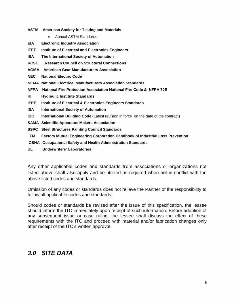
ASTM American Society for Testing and Materials
Annual ASTM Standards
EIA Electronic Industry Association
IEEE Institute of Electrical and Electronics Engineers
ISA The International Society of Automation
RCSC Research Council on Structural Connections
AGMA American Gear Manufacturers Association
NEC National Electric Code
NEMA National Electrical Manufacturers Association Standards
NFPA National Fire Protection Association National Fire Code & NFPA 70E
HI Hydraulic Institute Standards
IEEE Institute of Electrical & Electronics Engineers Standards
ISA International Society of Automation
IBC International Building Code (Latest revision in force on the date of the contract)
SAMA Scientific Apparatus Makers Association
SSPC Steel Structures Painting Council Standards
FM Factory Mutual Engineering Corporation Handbook of Industrial Loss Prevention
OSHA Occupational Safety and Health Administration Standards
UL Underwriters’ Laboratories
Any other applicable codes and standards from associations or organizations not
listed above shall also apply and be utilized as required when not in conflict with the
above listed codes and standards.
Omission of any codes or standards does not relieve the Partner of the responsibility to follow all applicable codes and standards.
Should codes or standards be revised after the issue of this specification, the lessee should inform the ITC immediately upon receipt of such information. Before adoption of any subsequent issue or case ruling, the lessee shall discuss the effect of these requirements with the ITC and proceed with material and/or fabrication changes only after receipt of the ITC’s written approval.
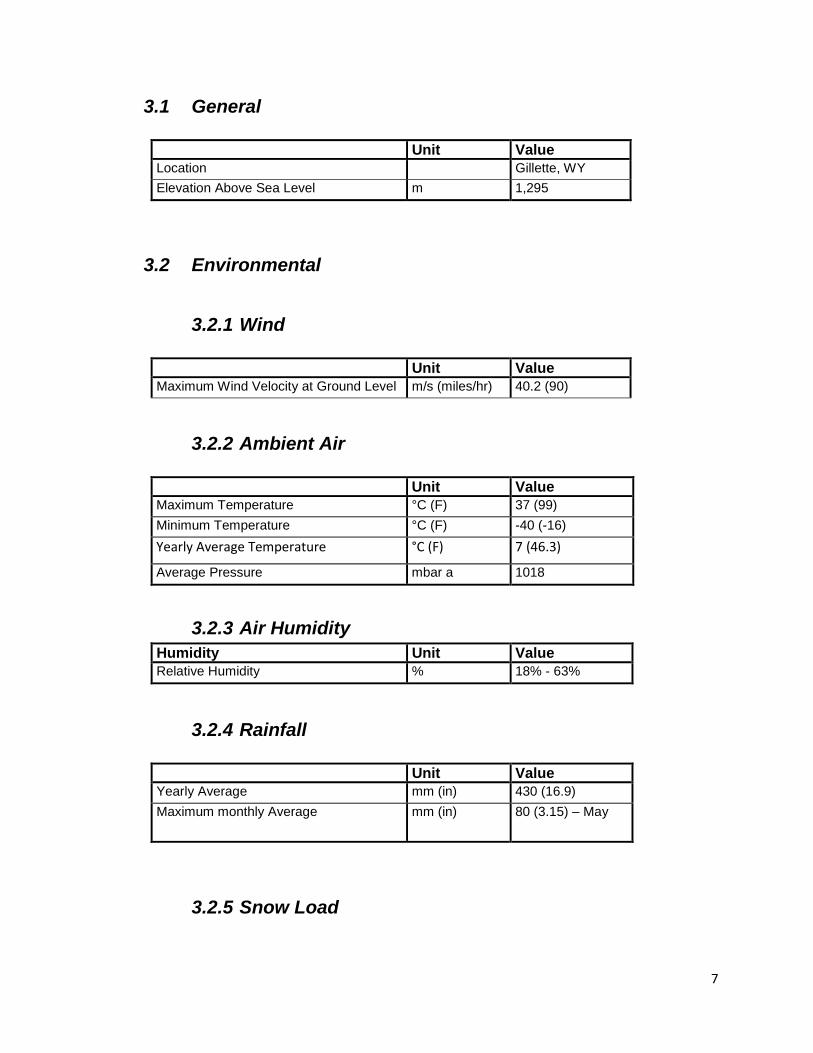
3.0 SITE DATA
7
3.1 General
Unit Value
Location Gillette, WY
Elevation Above Sea Level m 1,295
3.2 Environmental
3.2.1 Wind
Unit Value
Maximum Wind Velocity at Ground Level m/s (miles/hr) 40.2 (90)
3.2.2 Ambient Air
Unit Value
Maximum Temperature °C (F) 37 (99)
Minimum Temperature °C (F) -40 (-16)
Yearly Average Temperature °C (F) 7 (46.3)
Average Pressure mbar a 1018
3.2.3 Air Humidity
Humidity Unit Value
Relative Humidity % 18% - 63%
3.2.4 Rainfall
Unit Value
Yearly Average mm (in) 430 (16.9)
Maximum monthly Average mm (in) 80 (3.15) – May
3.2.5 Snow Load
8
Snowfall is 150 mm (59) from September to May.
Note: 2009 IBC Ground Snow Fall = 10 lb/sqft = 49 kg/m2
4.0 SITE ACCESS
In order to ensure the safety and security of all personnel at the ITC, all visitors must supply the information below before arriving at the plant site.
4.1 Initial Site Access
Prior to an initial visit to the site visitors should supply the following information for each visitor that will be in attendance:
For U.S. Citizens – First and Last Name Company Name For Citizens of other countries – First and Last Name Company Name
Country of Citizenship Name of Home Town
Visitors should provide two forms of identification upon visit to site. Acceptable forms of identification are an unexpired, "official" state or federal identification credential, which includes the individual's picture AND an *original social security card, current employer provided W-4 or W-2 form, or an official document from the Social Security Administration. Additional information is included in the link in section 4.2. Sub-lessors selected by WIA will be required to sign off on DFS entry requirements prior to initial site access.
4.2 Working on Site
For lessees that will have employees or contractors coming to the site to do work in the field, the Dry Fork Station Plant Access Requirements must be followed. A summary of the screening process is:
Prior to a lessee beginning any work on site, the contract between the lessee and the WIA must be finalized.
Provide the ITC with the individual’s information as described in section 3.2.1 (if this has not already been done).
Provide a photo ID and valid SSN document (or passport).
Complete Site Safety orientation.
A background check will be required.
The company must have a drug-screening process.
9
5.0 TEST FACILITIES
The flue-gas slip-stream is taken downstream of the scrubber - providing up to 20 MWe of cleaned flue gas to the ITC. The ITC site has two flue gas induced draft fans. The first provides flue gas to the Large Test Center Bay(s) (LTC), 5MWe to 18MWe of gas. The second supports five pilot bays and has a 0.4MWe capacity per bay.
6.0 UTILITIES
Electricity:
Powder River Energy Corporation (PRECorp) is the provider. It is the responsibility of the lessee to secure the service.
Large Test Center: 25kV-480V, 3000 kVA transformer
Small test Center: 25kV-480V, 750 kVA transformer
Water:
Domestic: 20 gallons per hour (gph)
No charge for water
Water pressure: Domestic at 60 psig and service water at 80 psig.
Drinking water quality meets standards and service water is from deep well
Service/cooling Water: The LTC is supplied with 300 gpm with return
No process cooling water provided above the water limits cited above
The large test center tenant is to provide a pump for wastewater discharge to the sump.
Compressed Air:
Not provided by Dry Fork Station, this is the responsibility of the lessee
No Natural gas nor LPG on site
Flue Gas:
A Guillotine damper for the Large Test Center and butterfly valve for the Small Test Center will allow for gas to flow, both are controlled by the Dry Fork Station Digital Control System (DCS).
After processing, the flue gas discharge procedures and details are the responsibility of the technology developer.
There will be no specific bay flue gas flow rate measurement mechanism, but DFS will have capability to measure the flow rate to the entire LTC and STC as a whole.
6.2 Flue Gas Supply
Flue gas is supplied to the lessee with the following approximate composition for normal coal derived flue gas:
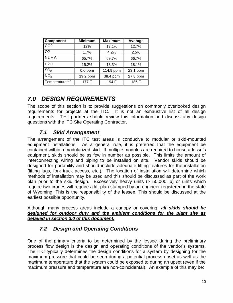
10
Component Minimum Maximum Average
CO2 12% 13.1% 12.7%
O2 1.7% 4.2% 2.5%
N2 + Ar 65.7% 69.7% 66.7%
H2O 15.2% 18.3% 18.1%
SO2 0.0 ppm 114.9 ppm 23.1 ppm
NOx 19.2 ppm 38.4 ppm 27.8 ppm
Temperature (1)
177 F 194 F 185 F
7.0 DESIGN REQUIREMENTS The scope of this section is to provide suggestions on commonly overlooked design requirements for projects at the ITC. It is not an exhaustive list of all design requirements. Test partners should review this information and discuss any design questions with the ITC Site Operating Contractor.
7.1 Skid Arrangement
The arrangement of the ITC test areas is conducive to modular or skid-mounted equipment installations. As a general rule, it is preferred that the equipment be contained within a modularized skid. If multiple modules are required to house a lesse’s equipment, skids should be as few in number as possible. This limits the amount of interconnecting wiring and piping to be installed on site. Vendor skids should be designed for portability and should include adequate lifting features for the installation (lifting lugs, fork truck access, etc.). The location of installation will determine which methods of installation may be used and this should be discussed as part of the work plan prior to the skid design. Excessively heavy units (> 50,000 lb) or units which require two cranes will require a lift plan stamped by an engineer registered in the state of Wyoming. This is the responsibility of the lessee. This should be discussed at the earliest possible opportunity. Although many process areas include a canopy or covering, all skids should be designed for outdoor duty and the ambient conditions for the plant site as detailed in section 3.0 of this document.
7.2 Design and Operating Conditions
One of the primary criteria to be determined by the lessee during the preliminary process flow design is the design and operating conditions of the vendor’s systems. The ITC typically determines the design conditions for a system by designing for the maximum pressure that could be seen during a potential process upset as well as the maximum temperature that the system could be exposed to during an upset (even if the maximum pressure and temperature are non-coincidental). An example of this may be:
11
Normal Operating Conditions: 15’’ H2O @ 185 F High Pressure Upset Condition: 30’’ H2O @ 185 F High Temperature Upset Condition: 15’’ H2O @ 350 F Resulting Design Conditions for all components: 30’’ H2O @350 F In this example above, the values indicate the worst case expected pressure and temperature at non-coincidental conditions. Using these conditions simultaneously yields a more conservative design. It is recommended that lessee use a similar philosophy for determining their design conditions. Once the design conditions of the vendor skid have been determined, the existing ITC over-pressure and over-temperature controls in the area of installation can be evaluated to determine if they provide adequate safeguards for the vendor skid. If not, additional over-pressure and/or over-temperature safeguards may be required. As this can cause substantial design and layout work, it is recommended that this evaluation be conducted as early in the design process as possible. A preliminary Process Hazard Analysis (PHA) is likely the most effective method of evaluating design conditions and system safeguards. This is discussed in further detail in Section 8.0 of this document.
7.3 Process Piping
All piping within vendor skids should be designed, fabricated, installed, tested, and inspected in accordance with ASME B31.1, or B31.3, whichever is applicable.
7.4 Pressure Vessels
Compliance with ASME Section VIII Boiler and Pressure Vessel Code is a site requirement and should be considered in the design and engineering of the vessel. Any pressure vessel not meeting code exemptions as outlined in section U-1 of the code are required to carry an ASME Code Stamp. As best practice, BEPC requests a copy of the vessel code calculations and U-1 report.
For many vendor tests conducted at the ITC, the small scale of testing often allows vendor vessels to meet the small size exemptions of the code as outlined in U-1(c)(2)(i), in which case a code stamp is not required. Even if a vessel is determined to be exempt, the BEPC believes that following the intent and requirements of the code for the design of exempt vessels is an engineering best practice and requests that a full set of code calculations be performed by an engineer who is experienced in pressure vessel design. The drawings, design, and calculations should be submitted to the BEPC for review prior to fabrication of the vessel. The test partner is also required to solicit a fabricator who is experienced in the fabrication of pressure vessels. The fabricator’s name and credentials must be supplied to the BEPC prior to fabrication as well.
12
7.5 Overpressure Protection
System overpressure scenarios for vendor skids should be evaluated during the design phase to determine where additional overpressure protection may be required. This evaluation should be completed by a competent engineer who is familiar with and experienced in the design, sizing, and selection of pressure relief devices. For each system or vessel, an analysis should be completed to identify all potential sources of overpressure as outlined in API 521. Once all valid sources of overpressure have been determined, appropriate overpressure protection should be included in the system design. When designing and selecting pressure relief devices, calculations of the relieving rate and proper valve sizing should be performed by the test partner’s qualified engineer. BEPC requests copies of all PSV sizing calculations performed by the test partner. In some cases, a system can claim to be protected from overpressure “by design,” meaning that the system is designed to withstand a higher pressure than can be introduced. Such a vessel can be exempt from the installation of a mechanical overpressure device, but only if the exemption criteria outlined in UG-140 of the BPVC are followed. However, the minimum recirculation line is designed to relief on pressure. For systems that may be exposed to vacuum (such as vessels potentially exposed to condensing steam) or external pressure (such as jacketed vessels), these conditions should be evaluated as well.
7.6 Electrical
BEPC can provide both 480V power and 208/120V power to developer’s skids. The BEPC will provide a single power feed for each voltage provided. Distribution to the lessee’s skid(s) should be provided by the developer. Hazardous Area classification for the skid is determined by the type of test, and location of the developer’s skid. Designs must meet or exceed requirements by the NEC, NFPA 497 and NFPA 499.
7.7 Engineer of Record
For lessee skids that are designed and constructed at the lessse’s facility, local and national construction codes should be followed. For any work that is to be executed in the field after equipment has been delivered to the ITC, all drawings and calculations must be stamped by an Engineer of Record in the State of Wyoming .
13
8.0 PROCESS SAFETY
8.1 Design Hazard Analysis
For projects to be implemented at the ITC, it is not uncommon to have more than one process hazard analysis or design hazard analysis. Each analysis may be performed as a HAZOP, What-if, or other generally accepted type of PHA. PHA’s typically conducted for projects at the BEPC are: Test Partner Preliminary Hazard Review
This review can be conducted based on process flow diagrams or preliminary P&ID’s. The purpose of this review is to identify any obvious issues that could impact the project scope or design. Understanding the process intent, raw materials, process streams, etc. may allow the Operating Contractor personnel to advise the lessee in determining which types of process safeguards are needed for the vendor system so that they can be incorporated into the initial system design. This is often a good time to identify the highest priority/highest impact process safety parameters. As this hazard review is informal and preliminary, a facilitator is not required. This review can potentially be conducted via video/web/telecon. It is often conducted prior to the “Tier 1” information being completed (see section 9.3.1) Test Partner Formal Hazard Analysis This is the formal hazard analysis for the lessee’s process, and is most typically a HAZOP. The HAZOP should be led by a trained and experienced HAZOP facilitator who may be an employee or contractor for the test partner. Operating Contractor participation in this HAZOP is required. This can typically be arranged to take place at the ITC or at the Test Partner’s facility. At a minimum, the following documentation should be completed prior to the formal hazard analysis:
process design
design and operating conditions for each process flow
frozen piping and instrumentation diagrams (P&ID’s)
major equipment sizing and selection
piping specifications
process description
Startup, shutdown, emergency shutdown, and maintenance sequences
Interlock List and logic diagrams The above documentation should be provided to the Operating Contractor at least one week prior to the HAZOP. The completed HAZOP documentation showing the detailed resolution of all action items generated during the HAZOP must be provided to ITC prior to startup of the lessee’s unit.

14
ITC Design Hazard Review (DHR) This hazard review includes any design changes that the Operating Contractor implements (within ITC process boundaries) in order to facilitate the installation of the test partner. Lessee participation is not required in the DHR. Hazard Review for Design Changes It is desired that the P&ID’s, process, and design be as close to finalized as possible at the time that the Test Partner Hazard Analysis is completed. However, design changes are often made after the HAZOP process has been completed. For any substantial design changes that are implemented after the formal HAZOP has been conducted, a follow-up review for such changes must be conducted and incorporated with the initial HAZOP documentation. The definition of a “substantial design change” would be any change that would require a HAZOP if it were being performed as a stand-alone project. Such changes are typically associated with changes in process flow, process chemistry, overpressure or over-temperature protection, etc. Basin Electric Power Cooperative should receive notification that the HAZOP has been completed prior to delivering flue gas to the lessee.
8.2 Documentation
In addition to the documentation noted in other sections of this document, the BEPC requires that the lessee provide the following information at a minimum:
Safety Data Sheets (SDS) for all materials to be used on site prior to the delivery of the materials.
All operating, startup, shutdown, emergency shutdown, and maintenance procedures for the test partner’s process.
A list of all process interlocks for the test partner’s process.
A function check list that the test partner plans to execute during the commissioning phase of the project after construction is completed.
8.3 Pre-Startup Safety Review
Prior to startup of the lessee’s process, a Pre-Startup Safety Review (PSSR) is required. This review consists of a review meeting as well as a field walk-down of the test partner’s equipment. During the review meeting, the lessee and BEPC will review the project and process documentation to ensure completion of all documentation, verify that all DHR action items have been completed, and verify that all operating and process safety information has been received by BEPC. The field walk-down should evaluate the field construction for completeness and verify that the construction is representative of the design criteria. BEPC PSSR Procedure can be reviewed for additional details.

15
9.0 PROJECT MANAGEMENT
9.1 Division of Responsibility
During the engineering and design phase of the project, the Operating Contractor’s role is to review the lessee’s system and offer guidance on process safety standards. WIA and the Operating Contractor do not accept design responsibility for the lessee’s equipment or design. The following is NOT the responsibility of BEPC nor the WIA, and is solely the responsibility of the lessee:
Installing foundations for equipment
Unloading, installing, and anchoring skid(s)
Routing process gas supply/return, and utility piping to the boundary of the process
Routing a single electrical power supply with disconnect to the test partner’s skid
Commissioning and startup of the skid
9.2 Work Plan
The work plan will serve as an auxiliary to the contract between the ITC and the lessee and will be used to identify all scope to be executed. For example, if installation of the lessee’s equipment requires the use of a rental crane or if specialized bottled gases are required, the lessee is anticipated to assume these costs. The work plan should be negotiated and agreed upon before detailed design of the project installation proceeds.
9.2.1 Tier 1 Information
Tier 1 information is the preliminary, up-front documentation provided by the lessee. The WIA and its ITC Operating Contractor require this information to complete a preliminary process review. This information is to be provided by the lessee to include the following as a minimum:
General project background information and test objectives
Process Flow Diagram
Preliminary P&IDs
Material Safety Data Sheets
Major Equipment Specifications
Design Pressures and Temperatures for each line/component noted on P&ID’s
Process Description
16
Completed Work Plan that has been agreed to by the ITC Operating Contractor and the test partner
Desired pressures and capacities for all process flows (process gases, utilities, vents, waste streams, and electricity)
Estimated Motor Loads
Lessee Project Milestone Schedule
General dimensions of process skid(s)
Lessee’s gas analysis plan (what samples, what analysis and when)
9.3 Scheduling
The ITC will make every effort to accommodate the lessee’s schedule goals for implementation of projects and will keep the lessee advised of open test opportunities at all phases of the project. In order to implement as many successful tests for as many partners as possible, the ITC must focus our operating engineering and technical resources on the projects for which all of the required information has been supplied. Because delay in receiving information from the lessee can greatly impact the schedule of a project, the operating contractor utilizes the tiered information system to assist the lessee in understanding what information is required at each stage of the process.
9.4 Data Requirements
Developers who test at the ITC are required, as part of the facility’s contractual obligations to its lessees, to report certain elements related to testing their technologies. The intent is to provide project partners and the public with the data necessary to make educated decisions on the state of carbon capture technologies and to gauge the readiness level of these technologies for commercialization. Trade secrets or other proprietary information are not required to be made public and every effort to protect them will be made. To protect this information, data is classified into the following general structure based on the types of information that will be requested by the WIA ITC and project partners:
A.) Unlimited Rights Data (public, unrestricted data) B.) Performance technical, Scale up potential and Economic Data C.) Technical Data Not Required to be Delivered, Proprietary Data on process
and methodology. D.) Protected Rights Data
10.0 INSTALLATION/CONSTRUCTION
For any field work to be completed within the boundary of the lessee’s equipment, the lessee shall provide experienced and qualified site designated installation and commissioning personnel who will be active in providing technical direction for equipment installation and mechanical completion, commissioning, performance and
17
acceptance testing of all items under the partner’s scope of supply. Depending on the size and scope of the construction work to be performed, a dedicated safety manager (who is experienced in the field of safety supervision) may be required. If this is deemed necessary, it is the responsibility of the lessee or the lessee’s contractor to provide.
11.0 OPERATION
11.1 Operators
Lessees should provide qualified and experienced field operators for the startup and shutdown of their system. If the lessee determines that operation of the unit requires more frequent or continuous monitoring, the lessee shall provide their own qualified operators. Operators should be experienced in industrial process operations. BEPC may request operator credentials prior to startup.
11.2 Control Systems
Lessee`s skids should be operated and controlled locally.
12.0 DISPOSITION OF MATERIALS
At the conclusion of testing, any raw materials such as catalysts, solvents, or spent sorbents must be removed from the site by the lessee.
13.0 HOMELAND SECURITY
Any chemicals on the plant site must be evaluated to determine if they are considered a “DHS Chemical of Interest.” The lessee must determine if the composition or concentration of a component may trigger a notification or screening as outlined in 6 CFR Part 27 - CHEMICAL FACILITY ANTI-TERRORISM STANDARDS. If so, this should be brought to the attention of BEPC personnel as soon as possible


