Project Manual for the construction of HILLTOP SERVICE CENTER ARCHIVES RENOVATION PHASE II Volume I: Divisions 1 - 10 Site Number: 891 2800 West 7 th Avenue, Denver, CO 80204 Denver Public Schools School District Number 1 Denver, Colorado 80202 August 5, 2014 DESIGN TEAM: ARCHITECT: RTA, Inc. MEP ENGINEER: ME Group PUBLICATION DATE: AUGUST 5, 2014 RTA PROJECT NO.: 12035.02 DPS SITE NO: 891 DPS PROJECT NUMBER: 2240 100% Construction Documents SET NO.
Transcript
Project Manual for the construction of
HILLTOP SERVICE CENTER ARCHIVES RENOVATION PHASE II Volume I: Divisions 1 - 10 Site Number: 891 2800 West 7th Avenue, Denver, CO 80204 Denver Public Schools School District Number 1 Denver, Colorado 80202 August 5, 2014
DESIGN TEAM: ARCHITECT: RTA, Inc. MEP ENGINEER: ME Group PUBLICATION DATE: AUGUST 5, 2014 RTA PROJECT NO.: 12035.02 DPS SITE NO: 891 DPS PROJECT NUMBER: 2240
100
% C
onst
ruct
ion
Doc
umen
ts
SE
T N
O.
Hilltop Service Center Archives Renovation – Phase II August 5, 2014 Denver Public Schools
Requirements for eligibility to bid Bond Requirements Insurance Requirements Subcontractors and Sub-contractors Contractor’s Performance Bond Builder’s Risk Pollution Coverage Certificates of Insurance Additional Insured Endorsements
Other General Requirements Failure to Insure
Waiver of Subrogation Bid Form
DIVISION 01 - GENERAL REQUIREMENTS 011010 Summary of Work 01127 Allowances 012300 Alternates 01270 Unit Prices 013000 Moving and Storage 01310 Project Management and Coordination 01315 Mechanical and Electrical Coordination 01320 Construction Progress Documentation 01330 Submittal Procedures 01400 Quality Requirements 01410 Regulatory Requirements 01420 References 01500 Temporary Facilities and Controls 01600 Product Requirements 01700 Execution Requirements 01731 Cutting and Patching 01732 Selective Demolition 01733 Alteration Project Procedures 017700 Closeout Procedures 017810 Project Record Documents 017820 Operation and Maintenance Data
DIVISION 10 - SPECIALTIES 101400 Interior Signage 102113 Toilet and Shower Compartments 102813 Toilet and Bath Accessories
DIVISION 11 - EQUIPMENT Not Used
DIVISION 12 - FURNISHINGS Not Used
DIVISION 13 - SPECIAL CONSTRUCTION Not Used
DIVISION 14 - CONVEYING EQUIPMENT Not Used
DIVISIONS 15 Not Used
DIVISIONS 16-20 Not Used
Hilltop Service Center Archives Renovation – Phase II August 5, 2014 Denver Public Schools
TABLE OF CONTENTS Page 3 of 4
DIVISION 21 - FIRE SUPPRESSION Not Used
DIVISION 22 – PLUMBING 220500 Common Work Results for Plumbing 220519 Meters and Gages for Plumbing Piping 220523 General-Duty Valves for Plumbing Piping 220529 Hangers and Supports for Plumbing Piping and Equipment 220553 Identification for Plumbing Piping and Equipment 220700 Plumbing Insulation 221116 Domestic Water Piping 221119 Domestic Water Piping Specialties 221316 Sanitary Waste and Vent Piping 221319 Sanitary Waste Piping Specialties 224000 Plumbing Fixtures
Division 23 - Heating, Ventilation, and Air Conditioning (HVAC) 230130.51 HVAC Air-Distribution System Cleaning 230500 Common Work Results for HVAC 230500 Common Work Results for HVAC 230513 Common Motor Requirements for HVAC Equipment 230519 Meters and Gages for HVAC Piping 230523 General-Duty Valves for HVAC Piping 230529 Hangers and Supports for HVAC Piping and Equipment 230593 Testing, Adjusting, and Balancing For HVAC 230700 HVAC Insulation 230900 Instrumentation and Control for HVAC 233300 Air Duct Accessories 233416 Centrifugal HVAC Fans
DIVISIONS 24 - 25 Not Used
DIVISION 26 – ELECTRICAL 260501 Mechanical and Electrical Coordination 260519 Low-Voltage Electrical Power Conductors and Cables 260526 Grounding and Bonding For Electrical Systems 260529 Hangers and Supports for Electrical Systems 260533 Raceways and Boxes for Electrical Systems 260553 Identification for Electrical Systems 260923 Lighting Control Devices 262416 Panelboards 262726 Wiring Devices 262813 Fuses 262816 Enclosed Switches and Circuit Breakers 265100 Interior Lighting
DIVISION 27 - COMMUNICATIONS Not Used
DIVISION 28 - ELECTRONIC SAFETY AND SECURITY 283111 Digital, Addressable Fire-Alarm System
Hilltop Service Center Archives Renovation – Phase II August 5, 2014 Denver Public Schools
Hilltop PP2240 BID #: 14-MC-2240 DATE: August 5, 2014
Architect
RTA Architect 19 S. Tejon St. Suite 300
Denver, CO 80903
Denver Public Schools Construction Services / Strategic Sourcing
1617 S. Acoma St. Denver, Colorado 80223
14-MC-2240
VENDOR ACKNOWLEDGEMENT
Purpose: The purpose of this Solicitation is to provide Denver Public Schools a bid for Hilltop Archives Renovation described in the Scope of Work/Specifications and the Agreement.
Date: August 5, 2014
Proposal number: Bid No.: 14-MC-2240
Proposal title: Hilltop Archives Renovation Mandatory Pre-Bid Conference August 5, 2014, 9:00 am at
Hilltop Service Building front trailer 2800 W. 7
th Ave
Denver, CO 80204 Bids will be received until: August 21, 2014
2:00 PM, Local Denver Time at 1617 S. Acoma St., Denver, CO 80223
For additional information please contact: Michael Craig, Strategic Sourcing Email Address [email protected]
Documents included in this package: Vendor Acknowledgement Instructions to Vendors Bid Form Bid Bond Form Performance and Payment Bond Form Illegal Alien Certification Form Contractor Safety Statement Construction Agreement
Construction Agreement Exhibits General Conditions
Scope of Work/Specifications The undersigned hereby affirms that (1) he/she is a duly authorized agent of the Vendor, (2) he/she has read all terms and conditions, technical specifications and all other Solicitation Documents which were made available in conjunction with this Solicitation and fully understands and accepts them, (3) that the offer is being submitted on behalf of the Vendor in accordance with any terms and conditions set forth in this document, and (4) that the Vendor will accept any awards made to it as a result of the offer submitted herein for a minimum of ninety (90) calendar days following the date of submission.
VENDOR PRINT OR TYPE YOUR INFORMATION
(Include this form in your proposal)
Name of Company: ____________________________________________ Fax: _____________
***ALL PRE-BID MEETINGS WILL START PROMPTLY AT THE TIME STATED, ANY VENDOR ARRIVING AFTER THE SCHEDULED TIME WILL NOT BE PERMITTED TO BID***
In addition to matters appearing in the Base Bid form, all vendors shall pay close attention to the following:
SCHEDULE OF ACTIVITIES: The following activities outline the process to be used to solicit vendor responses and to evaluate each vendor proposal.
July 15, 2014 Distribute Invitation to Bid August 5, 2014 Mandatory pre-bid conference August 14, 2014 Deadline for submitting questions August 21, 2014 Bid due date October 31, 2014 Substantial Completion December 31, 2014 Final Completion
Sealed bids will be received by School District No. 1 in the City and County of Denver and State of Colorado at the Construction Services Offices, 1617 S. Acoma St., Denver, CO 80223. Attn: 14-MC-2240 Until 2:00 PM on August 21, 2014, at which time bids there will be a public bid opening.
Bids received after closing time of 2:00 P.M. will be returned unopened.
The project is to be substantially completed by October 31, 2014. The entire project is to be completed in time to be accepted by the District on or before December 31, 2014, or as otherwise provided for in the specifications.
1 Bid Forms: All forms used must be the forms prepared by the District. They include the following:
Base Bid
Bid Bond (unless the required Bid Guaranty is in the form of a cashier’s or certified check).
“BDOP Participation Report” submitted to BDOP (Business Diversity Outreach Program (formerly HUBS)) Coordinator within three (3) working days of bid date
Proof of Advertisement: For bids of $250,000 and above, the Contractor shall submit as part of bid documentation, a copy of contractor’s advertisement inviting bids from BDOP contractors as specified in the General Conditions
All blank spaces in these forms must be completely and correctly filled in with ink or typewriter. In case of conflict between words and numerals, the words will govern, unless obviously incorrect. A bid must be submitted on all alternates listed.
The Bid Bond (if this type of Bid Guaranty is used) must be accompanied by a duly executed Power of Attorney from the surety company.
NOTE: If Bid is by:
Individual
The person signing the Bid should state below his signature that he is the sole owner of his business.
Partnership
The partner signing the Bid should state that he is a partner of the firm making the bid.
Corporation
The officer signing the Bid must be the president or vice president of the corporation. He must state his title and make certain that the seal of the corporation is affixed and attested by the secretary or assistant secretary of the corporation.
Anyone signing a Bid as agent must submit with the Bid evidence proving that his signature thereto is binding upon his principal.
2 Submitting Bid: Bids must be submitted in duplicate (one original and one copy) in sealed envelopes marked as follows: (Faxed bids are not acceptable)
Name and Address of Vendor Bidding
Denver Public Schools
Construction Services Strategic Sourcing Department
1617 S. Acoma St.
Denver, CO 80223
ATTN: 14-MC-2240
Time of Opening: (Write on envelope the date and time set for the opening of bids.)
If delivered: Denver Public Schools, Construction Services, 1617 S. Acoma St., Denver, CO 80223 – attn: 14-MC-2240 Strategic Sourcing Dept. If bids are delivered on date due, it is suggested that vendors arrive one-half hour early to allow sufficient time for parking and receiving. There is limited parking on the street. Limited visitor parking is available in the paved DPS lot.
If mailed: Denver Public Schools, Attn: 14-MC-2240 Strategic Sourcing Dept., 1617 S. Acoma St., Denver, CO 80223.
If the bid is sent by mail, use registered mail. Enclose the sealed bid (envelope marked as indicated above) in the mailing envelope. No bid will be considered unless received prior to the time and at the place designated in the Advertisement for Bid.
Each bid must be submitted on a form prepared by School District No. 1 and must be accompanied by a Bid Guaranty in an amount not less than five per cent of the total bid price.
3 The Bid Guaranty may be (1) a cashier's check, (2) a certified check, or (3) a bid bond submitted on a form prepared by the School District. The Bid Guaranty must be payable to the School District as a guaranty that the bid submitted will not be withdrawn for ninety days after the opening of the bids, and that, if the bid is accepted, the vendor will, within the prescribed time, enter into the required formal Agreement with the School District and furnish the required Contractor's Performance Bond and Certificates of Insurance, the amount of such Bid Guaranty to be paid to the School District as liquidated damages if such guaranty is not fulfilled.
4 Method of Award: Award of individual contracts will be based upon the total amount of the base bid plus any alternates selected to be included in the contract. Selection of alternates will be based on the availability of funds. Alternates will be selected as judged by the District to provide the best value to the District within the funds available for the project.
5 Inconsistencies and omissions: Any seeming inconsistencies between any plans or specifications or provisions of the contract documents, or any other matter seeming to require explanation, must be inquired into by the prospective vendor at least 72 hours (excluding Sundays and holidays) prior to the time set for the opening of bids. Decisions of major importance on such matters will be issued in the form of addenda. All addenda shall become part of the contract documents and receipt of the same by the vendor must be acknowledged on the Base Bid form.
If any prospective vendor notices that any sheet or page or other portion of the contract documents is missing, it shall be his responsibility to obtain such missing sheet, page or other portion.
6 Approvals: Requests for approval of equal products or materials must be written and must be received by the architect at least seven (7) working days prior to the bid opening. Requirements for the form and content of such requests are included in the contract documents. No request for substitutions will be considered after bid opening.
7 ELIGIBILITY OF VENDORS - MUST BE ENGAGED IN SUPPLYING PRODUCTS OR SERVICES RENDERED: Pre-award inspection of the Vendor's facility may be made prior to award of the contract. Solicitations will only be considered from firms which have been engaged in the business of manufacturing or distributing the goods and/or performing services as described in this solicitation. The Vendors must be able to produce evidence that they have an established satisfactory record of performance for a reasonable period of time and have sufficient financial support, equipment and organization to ensure that they can satisfactorily execute the services if awarded a contract. The term equipment and organization as used herein shall be construed to mean a fully equipped and well established company in line with the best business practices in the industry and as determined by the proper authorities of the District. The District reserves the right, before awarding the contract, to require a Vendor to submit such evidence of its qualifications as it may deem necessary, and may consider any evidence available to it (including, but not limited to, the financial, technical and other qualifications and abilities of the Vendor, including past performance and experience with the District) in making the award in the best interest of the District.
Local office shall be required: Due to the service level required in conjunction with this Solicitation, the Vendor shall maintain an office within the Colorado, area. This office shall be staffed by a competent company representative(s) who can be contacted during normal business hours and who is authorized to discuss matters pertaining to the contract. Withdrawal of bids: Offers may be withdrawn prior to the time and date set for the opening. Such requests must be made in writing on company letterhead. Offers may not be withdrawn after the time and date set for the opening for a period of ninety calendar days. If an Offer is withdrawn by the Vendor during this ninety day period, the District may, at its option, suspend the Vendor from the bid list and may not accept any Offer from the Vendor for a six month period following the withdrawal.
8 Applicable laws and regulations: Each vendor will be assumed to be familiar with all state and local laws, charter provisions, codes, ordinances and regulations which might in any manner affect the work to be done or those to be employed in or about the work. No plea of misunderstanding or ignorance on the part of any successful vendor will in any way excuse such vendor from the necessity of full compliance with every such law, charter provision, code, ordinance and regulation.
i. Corporations and Partnerships: Vendors on public contract for services shall comply with the provisions of CRS §8-17.5-101 et seq., which requires a Contractor to certify that the Vendor and its sub-contractors do not knowingly employ illegal aliens on public contracts for services. Non-compliance with certification requirements may result in penalties including termination of the awarded contract. If so terminated, Contractor shall be liable for all actual and consequential damages; or
ii. Sole Proprietorships and Individuals: Vendors on public contract for services who are sole proprietors and persons eighteen years of age or older shall comply with the provisions of CRS §24-76.5-101 et seq., which requires the submission of a sworn affidavit that you are lawfully present in the United States before signing of the Agreement for any public benefit such as this contract. Any person who knowingly makes a false, fictitious, or fraudulent statement or representation in an affidavit shall be in violation of C.R.S. 18-8-503.
See the bid documents and the contract’s general terms and conditions for additional information.
9 Preference to Colorado Materials: The work shall be done by materials produced or manufactured in Colorado, provided Colorado materials can be obtained in marketable quantities and provided that such preference need not be given to materials of a quality inferior to the quality of the materials offered by competitors outside the state, although a differential of not to exceed 5% may be allowed in cost of Colorado materials of equal quality, all as provided by law.
10 Mandatory Pre-Bid Meeting: All prospective vendors are required to attend a mandatory pre-bid conference commencing at 9:00 AM local time, on August 5, 2014, at Hilltop 2800 W. 7
th Ave.
Denver, CO 80204. Independent inspections of the sites may be conducted by the vendors Monday through Friday from 3:00 p.m. – 5:30 p.m. during the bid period. The vendors must check into the school’s office to obtain a visitor’s pass and must also check out of the office.
11 Equal Opportunity: The District intends and expects that the contracting processes of the school district and its contractors provide equal opportunity without regard to gender, race, ethnicity, religion, age, or disability and that its contractors make available equal opportunities to the extent third parties are engaged to provide goods and services to the school district as subcontractors, vendors, or otherwise. Accordingly, the contractor shall not discriminate on any of the foregoing grounds in the performance of the contract and shall make available equal opportunities to the extent third parties are engaged to provide goods or services in connection with performance of the contract. The Vendor shall disseminate information regarding all subcontracting opportunities under this contract in a manner reasonably calculated to reach all qualified potential subcontractors who may be interested. The contractor shall maintain records demonstrating its compliance with this article and shall make such records available to the Owner upon the Owner’s request.
12 Intent to Award Notice: The recommendation for award shall be posted on the District's Strategic Sourcing Department web page at: (http://purchasing.dpsk12.org/bids/default.asp). It is the sole responsibility of the vendor to check the website periodically for the award recommendation. This shall serve as notice to all Vendors of the District's intent to make award to the lowest responsive/responsible Vendor(s). Vendors may request a copy of the tabulation sheet by emailing the buyer at [email protected]. If it is determined by the District that there are no Vendors that could be grieved by the award of this solicitation, The District reserves the right to waive or shorten the protest period and proceed with award.
13 APPEAL OF AWARD. Vendors may appeal by submitting, in writing, a detailed request for reconsideration to the District's Executive Director of Facility Management within 72 hours after the recommendation of award is posted on the Strategic Sourcing Department's web site at http://purchasing.dpsk12.org/bids/default.asp, provided that the appeal is sought by the Vendor prior to the District finalizing a contract with the selected vendor.
14 Execution of Documents: The vendor to whom the work is awarded will be required to execute three copies of the formal Agreement with the School District, on forms supplied by the District, to furnish, at the vendor's expense, three fully executed copies of the required Contractor's Performance and Payment Bond, and to furnish the requisite Certificates of Insurance and insurance endorsements, all within five (5) business days from the date of the Notice of Award. If such vendor fails to execute said Agreement and to furnish said Bond and Insurance documents within said five (5) day period, the District shall be entitled to collect the amount of such vendor's Bid Guaranty as liquidated damages, to consider all rights arising out of the District's acceptance of such vendor's Bid as abandoned and to award the work covered by such Bid to another, or to re-advertise the work, or otherwise dispose of the work, as the District may see fit.
16 Special Note to All Vendors: Each vendor shall be assumed to be familiar with the complete set of Contract Documents and to have given due consideration to all existing conditions and limitations under which the work is to be performed. The submission of a bid will be construed as conclusive evidence that the vendor has made such examination.
Vendor’s failure to comply with all the requirements for bid including documents to be submitted therewith, the use of proper forms, their proper and complete execution including the filling in of all blank spaces therein, may well result in the rejection of bid.
The School District reserves the right to reject any or all bids, to waive any informalities, and to accept any bid deemed desirable.
17 LIQUIDATED DAMAGES FOR DELAY
The liquidated damages amount to be applied under Section 3.5 of the General Conditions of the Contract for delays in Substantial Completion is $1000.00 per day.
The liquidated damages amount to be applied under Section 3.5 of the General Conditions of the Contract for delays in Final Completion is $500.00 per day.
18 Rejection: Vendor’s failure to comply with all the requirements for the bid including documents to be submitted therewith, the use of proper forms, their proper and complete execution including the filling in of all blank spaces therein, may result in a rejection of bid. This solicitation does not commit the District to award a contract, to pay any costs incurred in the preparation of a bid, or to procure or contract for the articles of goods or service. The District reserves the right to waive insignificant requirements, to accept or reject any or all bids or portions of bids for just cause received as a result of this request or to cancel in part or in its entirety this bid, if it is in the best interest of the District to do so.
DENVER PUBLIC SCHOOLS
SCHOOL DISTRICT NO. 1 IN THE CITY AND COUNTY OF DENVER
AND STATE OF COLORADO
CONTRACT DOCUMENTS
BID FORM
BASE BID TO: SCHOOL DISTRICT NO 1 IN THE
CITY AND COUNTY OF DENVER AND STATE OF COLORADO
PROJECT: Hilltop Service Center Archives Renovation
LOCATION: 2800 W 7th
Ave, Denver CO 80204
14-MC-2240
School Bid Amount
Hilltop Archives Renovations Base Bid $______________________________
Alternate 1 – Lighting Replacement on lower level at Fcombs and Loading Dock areas $
Alternate 2 – Lighting Replacement on lower level in areas identified $
Alternate 3 – Construction of wellness area, chain link fence and relocation of existing shelving and materials on lower level $
Alternate 4 – Construction of wellness shower rooms 116A & 116B $
Alternate 5 – Construction of Ricoh area, lower level restrooms, chain link fence area $
Unit Price 1 – Wall & ceiling repair (Hourly) $
Unit Price 2 – Moving services & supplies (Hourly) $
14-MC-2240 Project Experience Qualifications Sheet Must list 1 project of at least $200,000 and 3 projects of at least $100,000
Project Value Location Owner Reference
Contact Name Reference
Contact phone
DENVER PUBLIC SCHOOLS SUPPLIER PORTAL
Effective July 1, 2013, all new business conducted with DPS will require you to be registered on the DPS Supplier Portal. The Denver Public Schools (DPS) District is modernizing its Financial Management and Strategic Sourcing business processes to include two-way web-based communication with its Suppliers and Vendors. The benefits extended to our supplier/vendor business partners that register with DPS include:
Electronic Bidding Events/Solicitations. o Bids and Proposals sent directly to your personal Supplier Portal account o On-line bid responses, negotiations, awards, and much more
Direct submission of electronic invoices (depending on your contractual relationship).
Complete view of your contracts, purchase orders, invoices and payments online through your “Supplier Portal”.
Ability to maintain your business profile, points of contact, diversity qualifications, list of commodities you wish to provide, W-9s, certifications and insurance documentation, along with optional subcontractor tracking.
Historical record of your interaction and performance with DPS
Access to the supplier portal can be found here: http://purchasing.dpsk12.org/ Supplier Portal User Guides are available at same link (under the ‘Suppliers/Vendors’ link on the right-hand of the page).
IN THE CITY AND COUNTY OF DENVER AND STATE OF COLORADO
PROJECT: LOCATION: KNOW ALL MEN BY THESE PRESENTS: That we [the Contractor] _____________________ [hereinafter called “Principal”], and _________________________ [ hereinafter called “Surety”], a corporation organized and existing under the laws of _______________ and duly authorized to transact such business in Colorado, are held and firmly bound unto School District No. 1 in the City and County of Denver and State of Colorado [hereinafter called “Obligee”], in the sum of five per cent (5%) of the Principal’s total bid price as lawful money of the United States, for the payment of which sum, well and truly to be made to the Obligee, the Principal and Surety bind themselves, their heirs, executors, administrators, successors and assigns, jointly and severally, firmly by these presents. WHEREAS, the Principal is submitting a proposal, or bid, for the above described project for the Obligee, and said Obligee has required as a condition for receiving said proposal that it be accompanied by the specified Proposal Guaranty in an amount not less than five percent (5%) of the Principal’s total bid price, in pursuance of which requirement this Bid Bond is made, executed, and delivered. Now, the condition of this obligation is such that if the Principal shall maintain said proposal or bid in full force and effect for ninety days after the opening of the bids for such project, or, if the Principal’s proposal or bid is accepted, the Principal shall, within the prescribed time, enter into the required formal Agreement with the Obligee, furnish the required Certificates of Insurance and furnish the required Contractor’s Performance Bond, then this obligation shall be null and void, otherwise it shall remain in full force and effect. Signed, sealed, and delivered this __________________day of ____________________, 20___ (SEAL)
PRINCIPAL
Attest: By _____________________________ By _____________________________ Title ____________________________ Title ____________________________ (SEAL) SURETY By _______________________________ Attorney-in-Fact
THIS BOND MUST BE ACCOMPANIED BY A POWER OF ATTORNEY
BID BOND
SCHOOL DISTRICT NO.1 IN THE CITY AND COUNTY OF DENVER
AND STATE OF COLORADO
PERFORMANCE AND PAYMENT BOND Bond No._________ (the “Bond”) KNOW ALL MEN BY THESE PRESENTS that _________________________________________________________ _______________________________________________________________________________________________________________________, as Principal (the “Principal”), and _______________________________________ _______________________________________________________________________________________________________________________________________________, a corporation organized and existing under the laws of the State of _______________________, and authorized to transact business in the State of Colorado, as Surety (the “Surety”), jointly and severally, bind themselves, their heirs, personal representatives, successors, and assigns to the SCHOOL DISTRICT NO.1 IN THE CITY AND COUNTY OF DENVER AND STATE OF COLORADO (the “Owner”), in the principal amount of _________________________________________________________ ($______________) as adjusted by approved change orders (not to exceed ten (10) percent of the principal amount of this Bond unless expressly approved by the Surety, which approval shall not be unreasonably withheld) and interest as provided by law (collectively referred to herein as the “Penal Sum”), for the performance of and payment of all amounts due under the agreement between the Principal and the Owner, dated _______________, 20__, (the “Agreement”) for the following project: _______________________________________________________ (the “Project”), together with the obligations of the Contract Documents, as defined in the Agreement, all of the documents are incorporated by this reference and shall be, collectively, referred to as, the “Contract”. The condition of this obligation is such that, if the Principal shall at all times duly, promptly, and properly perform all the terms and conditions of the Contract and any authorized modifications thereof during the original term of the Contract, any extensions thereof that may be granted by the Owner, and during the term of any guarantee or warranty required under the Contract; and promptly make payment of all amounts, claims, or demands lawfully due to all persons, firms, associations, or corporations supplying or furnishing to the Principal or its subcontractors labor or materials, supplies, or equipment which are used, provided, or performed in the prosecution of the work provided for in the Contract and any and all duly authorized modifications of the Contract that may hereafter be made, then the Principal and Surety shall have no obligation under this Bond, otherwise, it shall remain in full force and effect and the Surety shall pay the full value of all payment amounts, claims or demands lawfully due and shall indemnify and hold the Owner harmless from all payments which the Owner may be required to make under the Contract or applicable law in excess of the Contract price not exceeding the amount of this obligation, together with interest as provided by law, as well as attorneys’ fees and costs incurred by the Owner in the resolution of any claim. Whenever the Owner terminates the Contract in accordance with the terms thereof, the Surety shall, within fifteen (15) calendar days after written notice of such termination, notify the Owner in writing of its election to complete the Contract in accordance with its terms, or notify the Owner that the Surety elects not to complete the Contract. If the Surety fails to give the written notice so required within such time period, then it will be deemed to have elected not to complete the Contract. Should the Surety elect to complete the Contract, it shall, within fifteen (15) additional calendar days following the date of receipt of the written notice of such election and with the Owner’s written approval, obtain a contractor to complete the work in accordance with the original Contract’s terms and conditions and thereafter proceed to work with due diligence and as the work progresses make available sufficient funds to pay the cost of completion less the balance of the Contract price. The Surety may not engage the Principal to complete the Contract, without the prior written consent of the Owner, which consent may be withheld at the sole and absolute discretion of the Owner.
If the Surety elects to complete the Contract, then it shall be entitled to receive the balance of the Contract price, less (i) any amounts paid by the Owner to the Principal; (ii) costs incurred by the Owner in correcting any defective work; (III) any additional legal, design professional, and other costs incurred by the Owner resulting from the Principal’s default; and (iv) liquidated damages caused by delayed performance or nonperformance of the Principal. Any progress payments, less retainage, due but not paid at the date of termination shall be paid to Surety so long as the Surety has agreed to indemnify the Owner for the amount thereof and no other claims have been made to such funds by subcontractors or suppliers in accordance with the Contract or applicable law. In the event the Surety elects not to complete the Contract, the Owner may then have the work completed by such means and in such manner, by contract with or without public bidding, or otherwise, as it may deem advisable. The Surety in such event shall at all times make available, sufficient funds, which at no time shall exceed the Penal Sum, as work progresses under the Contract between the Owner and its new contractor, and will pay the cost of the completion of the Contract pursuant to its terms, together with the other amounts set forth in sections (i) through (iv) above, but in no event shall the Surety be responsible for the payment of any sums to the Owner until the Owner has agreed to pay its total obligation according to the terms of the Contract, plus change orders, less deductions and claims chargeable by law or by the Contract, if any, and less the retainage which will be disbursed as proved by the Contract Documents and applicable law. The procedures set forth herein shall apply should there be a default and termination or a succession of defaults and terminations in fulfilling the terms and conditions of the work under the Contract. Any judgment recovered hereunder by the Owner shall include interest at the legal rate, together with reasonable attorneys’ fees and costs. IN WITNESS WHEREOF said Principal and Surety have executed this Bond, this _______________________ day of _____________________________A.D., 20_______.
WORKER STATUS CERTIFICATION STATEMENT REGARDING ILLEGAL ALIENS
[Reference HB 1343 – Certification]
CERTIFICATION STATEMENT FOR CORPORATIONS & PARTNERSHIPS The Vendor, whose name and signature appear below, certifies and agrees as follows:
1. The Vendor shall comply with the provisions of CRS 8-17.5-101 et seq.
2. The Vendor shall not knowingly employ or contract with an illegal alien to perform work under this
purchase order or enter into a contract with a subcontractor that knowingly employs or contracts with an illegal alien.
3. The Vendor represents, warrants, and agrees that it (i) has verified that it does not employ any
illegal aliens, through participation in the Basic Pilot Employment Verification Program administered by the Social Security Administration and Department of Homeland Security, or (ii) otherwise shall comply with the requirements of CRS 8-17.5-102(2)(b)(I).
4. The Vendor shall comply with all reasonable requests made in the course of an investigation by
the Colorado Department of Labor and Employment If the Vendor fails to comply with any requirement of this provision or CRS 8-17.5-101 et seq., the School District may terminate the above referenced purchase order for breach and the Vendor shall be liable for actual and consequential damages to the School District.
CERTIFIED and AGREED to this ______day of ____________ , 20__
_______________________________________ Name of Firm (print) _______________________________________ Signature of Authorized Representative _______________________________________ Name of Authorized Representative (print) _______________________________________ Denver Public Schools Project Name
DENVER PUBLIC SCHOOLS
WORKER STATUS AFFIDAVIT REGARDING ILLEGAL ALIENS
[Reference HB06:1023 – Certification]
AFFIDAVIT FOR SOLE PROPRIETORS & INDIVIDUALS
I, _______________________________, swear or affirm under penalty of perjury under the laws of the State of Colorado that (check one): ____ I am a United States citizen, or ____ I am a Permanent Resident of the United States, or ____ I am lawfully present in the United States pursuant to Federal law. I understand that this sworn statement is required by law because I applied for a public benefit. I understand that state law requires me to provide proof that I am lawfully present in the United States prior to receipt of this public benefit. I further acknowledge that making a false, fictitious, or fraudulent statement or representation in this sworn affidavit is punishable under the criminal laws of Colorado as perjury in the second degree under Colorado Revised Statute 18-8-503 and it shall constitute a separate criminal offense each time a public benefit is fraudulently received. _______________________________________ _________________ Signature Date _______________________________________ Name (print) _______________________________________ Denver Public Schools Project Name
DENVER PUBLIC SCHOOLS – DEPARTMENT OF FACILITY MANAGEMENT
Construction Safety Standards Acknowledgement Form
I have been informed that the Construction Safety Standards have been made available to me and that it is an OSHA and U.S. Department of Labor requirement that I must provide a safe workplace environment free from safety hazards. The DPS Construction Safety Standards may be found at:
http://bond.dpsk12.org/construction_standards
I am aware that the terms of the Construction Agreement provide that all Contractors shall have a written Safety and Health Program Plan that complies with current laws regarding worker health and safety and the prevention of accidents or injury to persons on or about the site (including the Occupational Safety and Health Act of 1970 as amended, the standards issued by the Secretary of Labor at 29 CFR Part 1926 and 29 CFR Part 1910 as amended, safety laws of the State of Colorado, and other safety laws and regulations). These written plans shall be available for Owner’s review at each worksite. Each Contractor’s employee is responsible for complying with applicable safety and occupational health requirements, wearing prescribed safety and health equipment, reporting unsafe conditions/activities, preventing avoidable accidents, and working in a safe manner. Contractor’s employees are required to wear the following minimum Personal Protective Equipment (PPE) while on Owner’s worksite: A. Hard Hat B. Safety Glasses C. Safety Vest D. Safety Shoes E. Safety Gloves if activity requires hand protection F. Other PPE as appropriate for work activity The Prime Contractor is responsible for ensuring subcontractor and sub‐sub‐contractor compliance with the safety and occupational health requirements as contained within the contractor’s written Safety and Health Program Plan.
The Contractor has been advised that part or all of their work may be performed within an area designated as a “Confined Space” or “Confined Space – Permit Required” zone within a DPS facility.
The Contractor’s responsibility is to perform all work in a safe manner to comply with all the terms of the Construction Agreement including having a written Safety and Health Program Plan that complies with current laws regarding worker health and safety and the prevention of accidents or injury to persons on or about the site (including the Occupational Safety and Health Act of 1970 as amended, the standards issued by the Secretary of Labor at 29 CFR Part 1926 and 29 CFR Part 1910 as amended, safety laws of the State of Colorado, and other safety laws and regulations).
It is the Contractor’s responsibility to comply with 29 CFR 1910.146 of the Occupational Safety and Health Act Regulation Standards pertaining to entering and working in a designated Confined Space area.
By acknowledgement of this provision, Contractor assumes all responsibility in performance of their work according to standard best safety practices.
Contractor acknowledges they have been informed of the hazard(s) found within the designated area, and is aware there may be additional hazards not yet identified.
The Prime Contractor is responsible for ensuring subcontractor and sub-subcontractor compliance with the safety and occupational health requirements as contained within the contractor’s written Safety and Health Program Plan.
DATE: _______
SIGNATURE: _______
PRINTED NAME:
COMPANY AND/OR CONTRACTOR: ______________________________________
DENVER PUBLIC SCHOOLS
SCHOOL DISTRICT NO. 1 IN THE CITY AND COUNTY OF DENVER
AND STATE OF COLORADO
Construction Agreement Construction Agreement Exhibits
General Conditions
DRAFT
Rev. 12/2009 943305.2
CONSTRUCTION AGREEMENT This CONSTRUCTION AGREEMENT (this “Agreement”) is entered into this ____ day of ____________, 20___, by and between School District No. 1 in the City and County of Denver and State of Colorado (the “Owner”) and ________________________________________ [full legal name], a _______________________ [state of formation and type of entity, e.g., “Colorado corporation,” “Colorado limited liability company,” etc.] (“Contractor”). In consideration of the covenants and agreements contained in the Contract Documents, the sufficiency of which is hereby acknowledged by the Contractor and Owner, Contractor and Owner hereby promise and agree as follows: Article 1. KEY TERMS; DESCRIPTION OF THE PROJECT
1.1 The Project. The “Project” consists of the construction of [an addition to] [a remodeling of] [a remodeling of part of] a building [or facility] known as ___________.
The principal function of this [building/facility] is [will be] __________________________.
Owner’s project number for the Project is ______________________.
The Project may be further described on Exhibit A
1.2 The Contract Sum.
.
1.2.1 The “Contract Sum” shall be the amount of $____________________, which shall be full compensation to the Contractor for all of the Work described in the Contract Documents.
1.2.2 General conditions costs shall be identified on the Schedule of Values, but there is no separate General Conditions Fee under this Contract.
1.2.3 There is no separate Contractor Fee under this Agreement. The Contract Sum includes Contractor’s profit and compensation for Contractor’s overhead and administrative expenses.
1.3 The Contract Documents. The “Contract Documents” include:
1.3.1 All written modifications or amendments to this Agreement, including Change Orders;
1.3.2 This Agreement, including all exhibits and attachments;
1.3.3 The General Conditions of the Contract;
1.3.4 Construction Documents prepared and approved in accordance with this Contract;
1.3.5 The following other documents, if any: _______________________________.
The Contract Documents are intended to be complementary, and anything required by any of the Contract Documents shall be as binding as if required by all of the Contract Documents. In the event of inconsistencies in requirements between different parts of the Contract Documents, unless Owner otherwise agrees in writing, Contractor shall provide the better quality or greater quantity. In the event of any irreconcilable difference between different provisions of the Contract Documents, the provision or requirement set forth in the Contract Document first appearing in the list above shall control.
-2-
1.4 Contractor’s Role in General; The Work. Contractor accepts the relationship of trust and confidence established with the Owner by the Contract Documents. Contractor agrees to furnish efficient business administration and superintendence and to use its best efforts to perform the Work in the best and most sound way and in the most expeditious and economical manner consistent with the interests of the Owner, within the time periods provided in the Milestone Schedule.
1.5 Exclusions. The scope of the Work shall not include, and Owner shall be responsible for, any items listed on Exhibit C
Article 2. DEFINITIONS AND INTERPRETATION
.
2.1 Defined Terms.
2.1.1 Terms Defined in the General Conditions of the Contract. Initially capitalized terms used but not defined in this Agreement shall have the meanings given them in the General Conditions of the Contract.
2.1.2 Agreement. This Construction Agreement, including exhibits hereto.
2.1.3 Contract Sum. Defined in Section 1.2.1
2.1.4 Contract Documents. Defined in
above.
Section 1.3
2.1.5 Owner Parties. Defined in
above.
Exhibit A
2.1.6 Project. Defined in
.
Section 1.1 above and Exhibit A
2.1.7 Self-Work. Any of the types of Work described on
.
Exhibit D
Article 3. PROGRESS PAYMENTS
and any other part of the Work as to which Owner consents in writing to performance by Contractor as Self-Work (which consent shall not unreasonably be withheld) to the extent that such work is actually directly performed by Contractor and is not performed through a Subcontractor.
3.1 Applications for Payment. In addition to the documents and information required by the General Conditions of the Contract, Contractor’s Applications for Payment shall include a statement in form approved by Owner setting forth (A) the percentage of the Work completed and the materials stored on the Site for the period ending the last day of the month for which the Progress Payment is requested for each category of the Schedule of Values, (B) the amount previously invoiced under the Contract, (C) the amount previously retained, (D) the net amount to be paid on the current Progress Payment (less applicable Retainage), and (E) the amount of the Contract Sum remaining unpaid if the requested payment is made in full.
3.2 Amount of Progress Payments. The net amount to be paid based on an Application for Payment shall be (a) the total of the amounts obtained by applying the percentage of completion for each line item in the Application for Payment to the price for that item in the Schedule of Values, less (b) the total amount of previous Applications for Payment.
Article 4. MISCELLANEOUS
4.1 Claims for Damages. Should either party suffer injury or damage to persons or property because of any act or omission of the other party or of any of its employees, agents, or others for whose acts it is legally liable, a claim shall be made in writing to such other party, with a copy to the Architect, within the time period required by the express terms of this Agreement and the
-3-
General Conditions of the Contract, or if not specified in this Agreement or the General Conditions of the Contract, within a reasonable time after such injury or damage.
4.2 Assignment; Successors and Assigns. Neither party to the Contract shall assign it or subcontract it as a whole without the written consent of the other. The Contractor shall not assign its interest in any amounts due or to become due to it under the Contract without the written consent of the Owner. Subject to the foregoing provisions of this Section, the Contract shall be binding upon and inure to the benefit of the parties hereto and their respective successors and assigns.
4.3 Entire Agreement. This Agreement, the General Conditions of the Contract, any other Contract Documents, and all exhibits thereto constitute the entire agreement between the parties with respect to the Project and all prior proposals are hereby terminated.
[The remainder of this page is intentionally blank.]
-4-
Signature page to Construction Agreement:
Executed to be effective as of the date first written above.
[Signature block for corporation as contractor:]
Contractor:
(CORPORATE SEAL) ATTEST: By: Print Name:
Date:
Title:
[Fill in full legal name of entity,] a Colorado corporation [if the entity was formed in another state, identify that state instead] By: Print Name:
Date:
Title: [Signature block for other entity:]
Contractor::
[Fill in full legal name of entity,] a Colorado [state type of entity: limited liability company, limited liability partnership, etc.] [if the entity was formed in another state, identify that state instead] By: Print Name:
Date:
Title:
[Owner signatures appear on the following page]
-5-
Signature page to Construction Agreement:
APPROVED AS TO FORM IN BEHALF OF
SCHOOL DISTRICT NO. 1:
James T. Allen
Date:
Interim Senior Director of Facilities
Office of the General Counsel
Date:
Trena Deane
Date:
Executive Director, Facility Management
David Suppes
Date:
Chief Operating Officer
(S E A L)
SCHOOL DISTRICT NO. 1
IN THE CITY AND COUNTY OF DENVER
AND STATE OF COLORADO
ATTEST:
Print Name:
Date:
Secretary, Board of Education
By:
Print Name:
Date:
President, Board of Education
-6-
TABLE OF EXHIBITS
A. Project Information and Certain Key Terms
B. Expenses Included in Cost of Work
B-1. Method of Payment Matrix
C. Schedule of Exclusions
D. Schedule of Permitted Self-Work
E. Arbitration Process
F. Equal Opportunity Construction Contracting Procedures
G. Schedule Requirements
H. General Conditions of the Contract
I. Supplementary General Conditions of the Contract (if any)
J. Federal Funding Provisions (if applicable)
J-1. Wage Determination (if applicable)
DRAFT
-i-
CONSTRUCTION AGREEMENT
TABLE OF CONTENTS
Article 1. KEY TERMS; DESCRIPTION OF THE PROJECT ................................................................ 1 1.1 The Project ..................................................................................................................................... 1 1.2 The Contract Sum ........................................................................................................................... 1 1.3 The Contract Documents ................................................................................................................ 1 1.4 Contractor’s Role in General; The Work......................................................................................... 2 1.5 Exclusions ....................................................................................................................................... 2
Article 2. DEFINITIONS AND INTERPRETATION ................................................................................ 2 2.1 Defined Terms. ............................................................................................................................... 2
Article 3. PROGRESS PAYMENTS ....................................................................................................... 2 3.1 Applications for Payment ................................................................................................................ 2 3.2 Amount of Progress Payments ....................................................................................................... 2
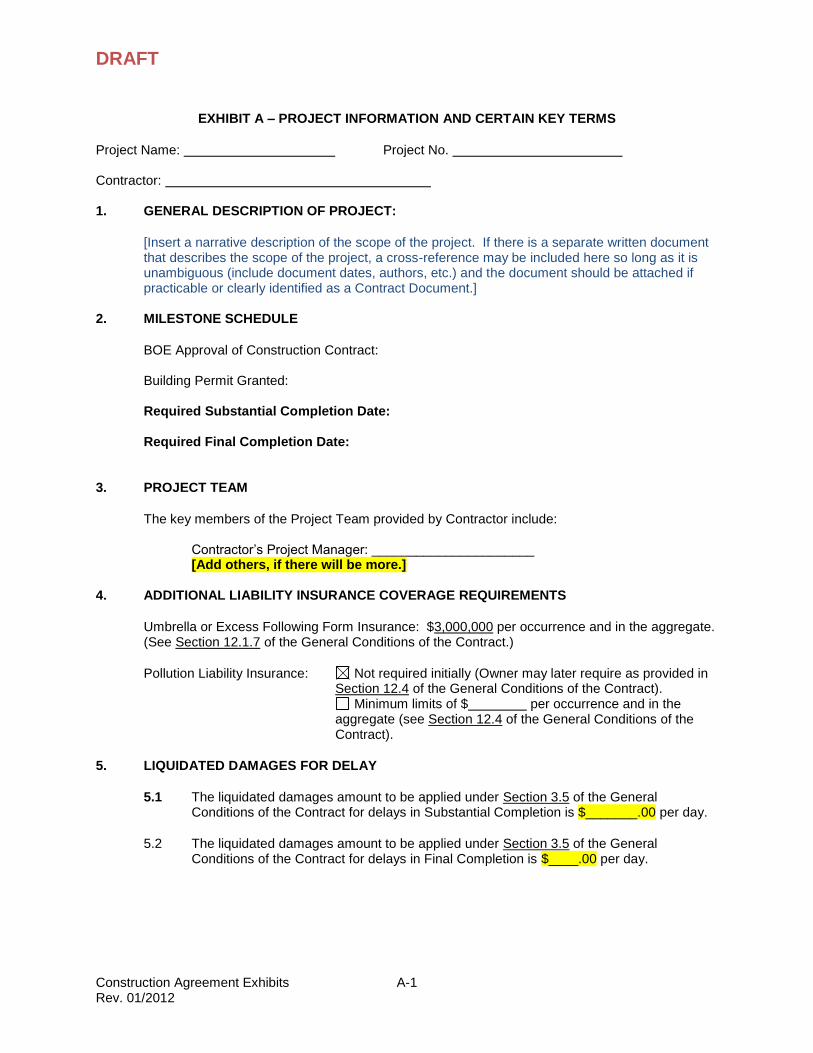
EXHIBIT A – PROJECT INFORMATION AND CERTAIN KEY TERMS
Project Name: Project No. Contractor: 1. GENERAL DESCRIPTION OF PROJECT:
[Insert a narrative description of the scope of the project. If there is a separate written document that describes the scope of the project, a cross-reference may be included here so long as it is unambiguous (include document dates, authors, etc.) and the document should be attached if practicable or clearly identified as a Contract Document.]
2. MILESTONE SCHEDULE
BOE Approval of Construction Contract: Building Permit Granted: Required Substantial Completion Date: Required Final Completion Date:
3. PROJECT TEAM
The key members of the Project Team provided by Contractor include:
Contractor’s Project Manager: ______________________ [Add others, if there will be more.]
Umbrella or Excess Following Form Insurance: $3,000,000 per occurrence and in the aggregate. (See Section 12.1.7 of the General Conditions of the Contract.)
Pollution Liability Insurance: Not required initially (Owner may later require as provided in Section 12.4 of the General Conditions of the Contract).
Minimum limits of $ per occurrence and in the aggregate (see Section 12.4 of the General Conditions of the Contract).
5. LIQUIDATED DAMAGES FOR DELAY
5.1 The liquidated damages amount to be applied under Section 3.5 of the General Conditions of the Contract for delays in Substantial Completion is $_______.00 per day.
5.2 The liquidated damages amount to be applied under Section 3.5 of the General Conditions of the Contract for delays in Final Completion is $____.00 per day.
A-2
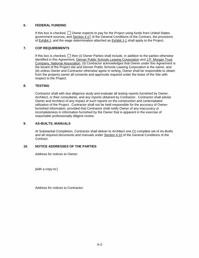
6. FEDERAL FUNDING
If this box is checked, Owner expects to pay for the Project using funds from United States government sources, and Section 4.17 of the General Conditions of the Contract, the provisions of Exhibit J, and the wage determination attached as Exhibit J-1 shall apply to the Project.
7. COP REQUIREMENTS
If this box is checked, then (i) Owner Parties shall include, in addition to the parties otherwise identified in this Agreement, Denver Public Schools Leasing Corporation and J.P. Morgan Trust Company, National Association, (ii) Contractor acknowledges that Owner under this Agreement is the tenant of the Project site and Denver Public Schools Leasing Corporation is the owner, and (iii) unless Owner and Contractor otherwise agree in writing, Owner shall be responsible to obtain from the property owner all consents and approvals required under the lease of the Site with respect to the Project.
8. TESTING
Contractor shall with due diligence study and evaluate all testing reports furnished by Owner, Architect, or their consultants, and any reports obtained by Contractor. Contractor shall advise Owner and Architect of any impact of such reports on the construction and contemplated utilization of the Project. Contractor shall not be held responsible for the accuracy of Owner-furnished information, provided that Contractor shall notify Owner of any inaccuracy or incompleteness in information furnished by the Owner that is apparent in the exercise of reasonable professionally diligent review.
9. AS-BUILTS, MANUALS
At Substantial Completion, Contractor shall deliver to Architect one (1) complete set of As-Builts and all required documents and manuals under Section 4.10 of the General Conditions of the Contract.
10. NOTICE ADDRESSES OF THE PARTIES
Address for notices to Owner: [with a copy to:] Address for notices to Contractor:
DRAFT
B-1
EXHIBIT B – COST OF WORK
The Contract Sum is a stipulated sum and does not vary according to the Cost of Work.
There is no Exhibit B-1.
DRAFT
C-1
EXHIBIT C – SCHEDULE OF EXCLUSIONS
The following items are excluded from the scope of the Work: 1. Architectural services. 2. [List others.]
DRAFT
D-1
EXHIBIT D – SCHEDULE OF PERMITTED SELF-WORK
[None]
DRAFT
E-1
EXHIBIT E – DISPUTE RESOLUTION
Disputes, concerning the interpretation of, the meaning of the construction documents or the performance of any work under this Agreement between Contractor and Owner (the “Parties”), which cannot be resolved by designated representatives of the parties shall be subject to the provisions and procedures of the Dispute Resolution hereof. Except as otherwise provided herein, with respect to any Dispute that may arise under this Agreement, it shall be a condition precedent of the Parties to stay any legal action and before pursuing any litigation in a court of competent jurisdiction, for the Parties to work, in good faith, to resolve all Disputes, including any legal claims, that may arising out of any Dispute under this Agreement and agree to follow the Dispute Resolution process and procedures up to and until a final decision rendered.
All Disputes shall be conducted in accordance with the following provisions unless Owner and
Contractor agree, in writing, that no Dispute which has not then already been submitted to Dispute Resolution, shall be subject to Dispute Resolution hereunder if one hundred eighty (180) days or more have passed since the Final Completion of the Project and one of the Parties has instituted litigation with respect to such Dispute before the time that Dispute Resolution of such Dispute has been demanded in accordance herewith. Capitalized terms not otherwise defined in this Exhibit shall have the same meanings assigned to them in the Agreement. 1. Good Faith Resolution. Any Dispute will initially be resolved informally. The Parties shall
attempt in good faith to resolve promptly any Dispute by negotiation between representatives who have authority to settle the dispute (“Authorized Representatives”). The Authorized Representatives must not be any person with direct responsibility for administration of this Agreement.
2. Executive Director. Any Dispute that is not resolved under Section 1 of this Exhibit E, shall be referred to the Executive Director of Facilities (the Executive Director”) who will render a final determination.
3. Notice of Demand for Dispute Resolution. In order to initiate Dispute Resolution, the Party demanding Dispute Resolution shall give the other Party telephonic notice of the demand and shall give written notice demanding Dispute Resolution to such Parties. Such written notice shall identify the issues in dispute. Any time periods based on the date of notice of the demand for Dispute Resolution shall be measured from the date such written notice is given in accordance with Article 16 of the Agreement.
4. Time and Place for Meeting. Upon written request from either Party to the Executive Director, the Executive Director shall schedule a meeting (the “Meeting”) at the Executive Director’s office within three (3) days of receipt of the request. Owner and Contractor shall both attend the Meeting with the Executive Director and each Party shall be represented as it determines to be appropriate. At or before the Meeting, either Party may, at its option, submit a short written statement describing the matter in dispute and its position in regard to the same. At the Meeting, the Parties shall show the Executive Director the parts of the Work or the drawings, or plans and specifications in dispute and each Party shall make such presentation of its case at the Meeting as its shall determine. The Meeting shall continue (including from day to day if required) until all presentations permitted by the Executive Director have been completed. Unless agreed to at the Meeting by the Executive Director, neither Party shall be entitled to make any submission after the Meeting as to any matter discussed at the Meeting.
5. Executive Director’s Decision. The Executive Director shall deliver a decision as to each issue discussed at a Meeting to the Parties promptly and, in any event, within five (5) business days following the conclusion of the Meeting as to any Dispute discussed at a Meeting. Each decision shall be rendered in a reasoned writing explaining the basis therefor in sufficient detail for a third party to understand the basis for the decision (the “Decision”). The Executive Director’s decision is final.
DRAFT
F-1
EXHIBIT F – EQUAL OPPORTUNITY CONSTRUCTION CONTRACTING PROCEDURES
1 OWNER’S POLICY
a) The policy of the Denver Public Schools with respect to equal opportunity contracting was established by Board of Education Resolution 2621. That policy commits the Owner to the creation and preservation of equal opportunities for all people to participate in the delivery of goods and services through the contracting processes of the Denver Public Schools without regard to gender, race, ethnicity, religion, age, or disability. It is the express expectation of the Board of Education that those who contract with the Owner shall in turn make available equal opportunities to the extent third parties are engaged to provide goods and services to the Owner as subcontractors, vendors, or otherwise.
b) Pursuant to resolution 2621, the contracting policies and practices of the Owner are to conform to the following parameters:
c) No person shall be excluded from participation in, denied the benefits of, or otherwise discriminated against in connection with the award and performance of any contract on the grounds of gender, race, ethnicity, religion, age, or disability.
d) Neither the gender, race, ethnicity, religion, age, nor disability of any contractor or subcontractor shall be a factor in the evaluation of any proposal or award of any contract.
e) Any party contracting with the Owner for the provision of goods or services shall be required to agree as a condition of the contract not to discriminate on any of the foregoing grounds in the performance of the contract.
f) Information regarding contracting opportunities with the Owner shall be disseminated in a manner calculated to reach all persons qualified to provide pertinent goods and services.
g) The criteria used in evaluating contract proposals shall be based on the Owner’s interest in securing cost effective, quality goods and services and shall not exclude or disadvantage parties for reasons that are not closely related to those interests.
h) In determining contract requirements care shall be taken to encourage submission of quotes or proposals from as wide a base of potential vendors as is reasonably possible.
i) Owner contracts for the provision of goods or services shall require that the contracting parties disseminate information regarding any third party contracting opportunities in a manner reasonably calculated to reach all persons qualified and willing to participate.
j) Owner contracts for the provision of goods or services shall require that the contracting party retain and make available to the Owner records regarding dissemination of information regarding third party contracting opportunities, including responses received by the contracting party.
2 DISSEMINATION OF INFORMATION
a) Pursuant to Resolution 2621 contracting opportunities and processes shall be disseminated as follows:
F-2
(1) Dissemination of Information by the Owner
(a) The Owner shall disseminate information regarding construction contracting opportunities by placing advertisements in a local newspaper of general circulation to all potentially interested contractors and subcontractors in the community. In addition, the Owner shall make plans available for construction projects in its Construction Services Office, in the offices of the project architect, and at suitable locations within the community where those plans may be reviewed by interested contractors and subcontractors free of charge.
(2) Dissemination of Information by Contractors
(a) Each contractor shall place advertisements inviting bids or proposals on all work not to be performed by the contractor itself. At minimum, such advertisements shall be placed in a newspaper or trade journal of general circulation within the Denver metropolitan area for at least one (1) day. Such advertising may be excused only with written permission of the Owner’s Construction Services office, under circumstances where such advertisement would be impractical or would not reasonably further the equal opportunity contracting policy of the Owner. A contractor participating in more than one project may consolidate its advertisements to save costs.
3 DATA COLLECTION AND REPORTING
a) Pursuant to Resolution 2621 the Owner’s Purchasing Department is responsible for collecting and maintaining information necessary to permit the Owner to determine the effectiveness of Owner contracting policies and practices in ensuring equal opportunity. Such information will be collected, maintained, and reported as follows:
(1) Subcontractor Bidding Phase
(a) Each Contractor shall promptly provide to the Owner’s Purchasing Director copies of advertisements placed pursuant to these procedures.
(b) The Contractor shall provide to the Owner’s Purchasing and Manager of the Business Diversity Outreach Program a completed Subcontractor Participation Report when the Contractor has collected the bids from which it intends to select Subcontractors. A form of this report is available from the Owner. The Contractor shall provide data on all subcontractors contacted during the bid period and on each bid received from all subcontractors. Such list shall identify which, if any, of the firms on the list are, to the best of the Contractor’s information, certified diverse businesses (“Certified Diverse Businesses”). Certified Diverse Business firms are defined for purposes of this procedure as businesses owned or controlled by Native Americans, Asian Americans, African Americans, Hispanics, or women. A business is deemed owned by whoever holds at least 51% of the equity interest in the enterprise. A business is deemed controlled by its chief executive officer (if the business is a corporation), its managing partner (if business is a partnership), the proprietor (if the business is a sole proprietorship), and in all cases by the person or persons with ultimate decision-making authority in the ongoing, day-to-day operation of the business. For a diverse business to become a Certified Diverse Business, the diverse business must obtain certification from a governmental agency, an industry recognized third party certification organization or the Owner may recognize the diverse business as “certified”.
F-3
(c) The information required by the preceding paragraph shall promptly be supplemented each time a subcontractor is replaced or an additional subcontractor is retained.
(d) To facilitate identification of Certified Diverse Businesses, the Owner will place on its Website the “Denver Public Schools Diverse Business Directory”. Contractors may also utilize the websites of the City & County of Denver, www.denvergov.org, Rocky Mountain Minority Supplier Development Council, www.rmmsdc.org, U.S. Small Business Administration, www.sba.gov, State of Colorado/DBE Certification, www.dot.state.co.us/eeo/certification, and Regional Transportation District, www.rtd-denver.com.
(e) The Owner’s Purchasing Department shall verify and compile all data received from contractors regarding Certified Diverse Business usage and shall report such data to the Board of Education. Each report shall set forth:
(i) The identity of each Certified Diverse Business firm
(ii) The type of work done by each Certified Diverse Business firm
(iii) The dollar amount of the contracts with such firms
(iv) The dollar amount of Certified Diverse Business participation on each specific project
(v) The dollar amount of Certified Diverse Business participation on all projects in total during any reporting period
(vi) The percentage of the dollar volume of Certified Diverse Business participation in each project
(vii) The percentage of the dollar volume of Certified Diverse Business participation on all projects in total
4 RECORDS RETENTION AND INSPECTION
a) Each contractor shall retain and make available to the Owner and its designees records sufficient to permit the Owner to ascertain compliance with the equal opportunity contracting requirements. The following records shall be maintained and made available for inspection by the Owner and its designees:
(1) All records reflecting any invitations to submit bids or proposals regarding subcontracting opportunities on any Owner project, including, but not limited to:
(2) Copies of advertisements placed by the contractor in any newspaper or trade journal
(3) Copies of requests for proposals or bid solicitations sent to any potential subcontractors, including names and addresses of each person or entity to whom such solicitations or proposals were sent
(4) Logs showing persons contacted by telephone or in person regarding bid opportunities
F-4
(5) All responses received to invitations to bid on subcontracting opportunities, including written responses and notes, memoranda, or other records of oral responses.
(6) All correspondence accepting, rejecting, qualifying, revising, or otherwise related to any invitation to bid subcontracting opportunities or responses thereto.
5 CONTRACT REQUIREMENTS
a) Pursuant to Resolution 2621 each Owner contract with any contractor shall contain the following provisions:
b) Denver Public Schools intends that the contracting processes of the Owner and its contractors provide equal opportunity without regard to gender, race, ethnicity, religion, age, or disability, and that its contractors make available equal opportunities to the extent third parties are engaged to provide goods and services to the Owner as subcontractors, vendors, or otherwise. Accordingly, the contractor shall not discriminate on any of the foregoing grounds in the performance of the contract and shall make available equal opportunities to the extent third parties are engaged to provide goods or services in connection with performance of the contract.
c) The contractor shall disseminate information regarding all subcontracting opportunities under this contract in a manner reasonably calculated to reach all qualified potential subcontractors who may be interested. The contractor shall maintain records demonstrating its compliance with this article and shall make such records available to the Owner upon the Owner’s request.
d) In implementing the foregoing provisions the contractor shall comply with and be bound by the Owner’s equal opportunity construction contracting procedures in all respects. Such procedures are hereby incorporated by reference and are made a material part of this contract, violation of which may be deemed grounds for termination of the contract by the Owner.
6 ENFORCEMENT
a) The Owner’s equal employment opportunity construction contracting requirements shall be enforced under the direction of the Owner’s Chief Operating Officer who shall cause to be implemented the following steps:
(1) Compliance Review
(a) Contractor compliance with the advertising and Certified Diverse Business identification requirements of these procedures shall be verified in each instance. In addition, contractor records shall be reviewed and the information contained in those records verified to such extent as the Chief Operating Officer deems appropriate to ensure compliance with these procedures.
(2) Complaints
(a) Any person who believes any person or firm has been subject to discrimination with respect to contracting opportunities, or that any contractor has failed to fulfill the requirements of these procedures, may file a complaint in writing with the Owner’s Purchasing Director, who shall cause a prompt investigation to be undertaken regarding that complaint.
F-5
(3) Reasonable Cause Notice
(a) If an audit, review, or investigation results in a determination of reasonable cause to believe that a contractor is not in compliance with these procedures, the Purchasing Director shall cause notice be given to the contractor in person or by registered mail identifying the area of noncompliance and requiring the contractor to show cause why specified sanctions should not be imposed. The notice shall advise the contractor that he may review the evidence supporting such reasonable cause determination and that he may submit a written response to such determination and request a hearing before the Chief Operating Officer regarding such determination and any sanction to be imposed. The notice shall further set forth the sanction proposed for such noncompliance.
(4) Hearing
(a) If a contractor requests a hearing regarding a reasonable cause determination, the Chief Operating Officer, or his designee shall hold a hearing at which such information and argument relevant to the determination shall be presented. The hearing shall be informal and the rules of evidence shall not be applied.
(5) Decision
(a) Following receipt of the contractor’s response to the reasonable cause notice, or following a hearing, if one is requested, the Chief Operating Officer, or his designee shall issue a decision making finding with respect to the contractor’s compliance or noncompliance with these procedures and imposing such sanctions, if any, as are appropriate. Such decision shall be final and binding.
(6) Contractor’s Cooperation
(a) Each contractor shall cooperate with the Owner in auditing, reviewing compliance, and investigating complaints. Such cooperation shall include maintaining and producing records required by these procedures and making available to the Owner personnel who have such information pertinent to these procedures. No contractor shall retaliate against any person or firm, or attempt to intimidate or coerce any person or firm for registering a complaint or cooperating with an investigation related to these procedures. Nor shall any contractor knowingly provide any false or inaccurate information in connection with any audit, review, or investigation.
(7) Sanctions
(a) Sanctions to be imposed for violations of these procedures may include one or more of the following:
(i) Forfeiture of opportunities to bid on Owner work for a specified time period or for specified projects
(ii) Disqualification from the Owner’s list of approved contractors that are considered for district-wide projects, either permanently, or for a specified time period
(iii) Contract termination
F-6
(iv) Such other sanctions as may be deemed appropriate to effectuate the purposes of these procedures
DRAFT
G-1
EXHIBIT G – SCHEDULE REQUIREMENTS
1. Electronic Data Format. The Project Schedule shall be developed and maintained using MS Project, Suretrack or another electronic system approved in writing by Owner.
2. General Requirements.
2.1 The Project Schedule shall include realistic activity sequences and durations, allocation of labor and materials, processing of shop drawings and samples, normal weather delays in accordance with Section 3.4.2 of the General Condition of the Contract and allowances for lead times in delivery of products. The Project Schedule shall provide for coordination with any separate construction activities by Owner that relate to or affect the Project (including any abatement, moving, or other occupancy requirements) and shall indicate the occupancy priority for different portions of the Site.
2.2 The Project Schedule shall be divided into logical building areas by floor levels, elevations, functional spaces and additions or renovations.
3. Submissions.
3.1 Contractor shall submit an updated Project Schedule with each Application for Payment. Each update shall include a time-scaled summary chart and a narrative report containing a description of the current status of the progress of the Work, current and anticipated delaying factors and their estimated impact on performance of other activities and completion dates, and an explanation of corrective actions taken or proposed to address any delaying factors. Such monthly submittal shall include a time-scaled Gantt chart and mathematical analysis in Portable Document Format (.pdf) and an electronic copy of the MS Project or Suretrack file that can be accessed to review all task relationships and all attached constraints.
3.2 Whenever the current update to the Project Schedule reflects a delay of five (5) or more working days behind schedule, Contractor shall submit, together with the Project Schedule update, a written statement describing the cause of the delay and the actions being taken or considered by the Contractor to recover the time lost.
3.3 Proposed changes to the Project Schedule shall be submitted to Owner’s Project Manager for review. Submissions of the Project Schedule proposing changes shall clearly identify the activities and/or logic affected by the proposed changes and compare such changes to the most recently accepted Project Schedule.
4. Detail Requirements. The Project Schedule shall, at a minimum, include the following detail and account for the following factors:
4.1 Activity durations in working days.
4.2 Long lead time procurement activities.
4.3 Contractor phasing activities.
4.4 Milestone dates for phasing requirements.
4.5 Owner activities (e.g. delivery of Owner-furnished items)
4.6 Resource constraints.
G-2
4.7 Interfaces with work by others (e.g. utility connections)
4.8 Concurrent activities by Owner’s separate contractors, to the extent they may interface with or otherwise affect the Work.
4.9 Inspection, commissioning and testing activities.
4.10 Clean-up and punchlist activities.
4.11 Owner move-in activities.
4.12 Weather constraints.
4.13 Change Directives and Agreed Changes.
4.14 Start, early start, late start, actual start, % complete, finish, early finish, late finish, remaining duration, actual finish, and total float for each activity.
5. Drawing and Analysis Details.
5.1 The CPM logic drawings included in the Construction Schedule shall be 30” x 42” and shall, at a minimum, include:
5.1.1 Activity descriptions.
5.1.2 Activity durations.
5.1.3 Marked critical path.
5.1.4 Marked complete activities.
5.1.5 Highlighted milestone dates.
5.1.6 The update number and date for the logic drawing.
5.2 The CPM computer analysis included in the Construction Schedule shall, at a minimum, include:
5.2.1 The activity designation.
5.2.2 The activity description.
5.2.3 The activity duration (in working days), early start, late start, early finish, and late finish dates, % complete, remaining duration, and total float.
5.2.4 Subcontract or trade designation.
DRAFT
H-1
EXHIBIT H – GENERAL CONDITIONS OF THE CONTRACT
(See Separate Attachment)
DRAFT
I-1
EXHIBIT I – SUPPLEMENTARY GENERAL CONDITIONS OF THE CONTRACT
(none)
General Conditions of the Contract Denver Public Schools 12/2011
School District No. 1 in the City and County of Denver and State of Colorado
General Conditions of the Contract
Article 1. DEFINITIONS AND INTERPRETATION
1.1 Definitions.
1.1.1 Terms Defined in Other Contract Documents. Terms defined in the Agreement or other Contract Documents and not defined herein shall have the meanings given them in the Contract Documents where they are defined.
1.1.2 Agreed Change. Defined in Section 5.1.2 below.
1.1.3 Agreement. The Agreement to which these General Conditions of the Contract are attached.
1.1.4 AHJ. The governmental authority having jurisdiction over the Project selected by Owner for building permits, inspections and approvals.
1.1.5 Application for Payment. Defined in Section 2.2.1.
1.1.6 Dispute Resolution. An Owner administrativeproceeding pursuant to the provisions of Exhibit E to the Agreement.
1.1.7 Dispute. A dispute subject to Dispute Resolution.
1.1.8 Architect. The architect, engineer, or other design consultant engaged by Owner in connection with the Project. If the Owner has not engaged such a person, references to the Architect shall be deemed to refer to the Owner unless otherwise expressly provided.
1.1.9 As-Builts. Defined in Section 2.5.1.4 below.
1.1.10 Change Directive. Defined in Section 5.1.1 below.
1.1.11 Change Order. Defined in Section 5.6 below.
1.1.12 CMGC Agreement. If these General Conditions of the Contract are used with a Construction Manager / General Contractor Agreement, that agreement.
1.1.13 Colorado Labor. “Colorado Labor” means any person who is a resident of the State of Colorado at the time of employment, selected without discrimination as to race, color, creed, sex, age, or religion, except when sex or age is a bona fide occupational qualification; provided that if C.R.S. § 8-17-101 is revised to provide a different definition of the term “Colorado Labor,” such term shall have the meaning provided in C.R.S. § 8-17-101.
1.1.14 Commencement of Construction. Defined in Section 14.7 for the purposes of that Section only.
General Conditions of the Contract 01/2012 2 Denver Public Schools
1.1.15 Construction Documents. The part of the Contract Documents comprised of the plans, specifications and other documents prepared by Architect, subject to Owner’s approval, to be used in the execution of the Work.
1.1.16 Construction Fee. If the Agreement is a CMGC Agreement, the term “Construction Fee” is defined in the Agreement. Otherwise, references in these General Conditions of the Contract to the “Construction Fee” shall mean the Contractor Fee.
1.1.17 Construction Work. The portion of the Work comprised of the physical construction of the Project, including supervision and administration thereof.
1.1.18 Contract. The agreement between Owner and Contractor relating to the Project contained in the Contract Documents.
1.1.19 Contract Documents. The Contract Documents identified in the Agreement.
1.1.20 Contractor. Defined in the Agreement. Where Contract Documents refer to a “Mechanical Contractor,” “Electrical Contractor,” or other specific contractors, those references mean “Contractor” when the work to be performed is part of the scope of Contractor’s Work.
1.1.21 Contractor Fee. If the Agreement is a CMGC Agreement, the term “Contractor Fee” is defined in the Agreement. Otherwise, the term “Contractor Fee” shall mean the part of the Contract Sum allocated in the Schedule of Values to Contractor’s profit, administrative and overhead expenses.
1.1.22 Contract Sum. Defined in the Agreement. If the Agreement is a CMGC Agreement, then adjustments in the Contract Sum to be made under these General Conditions of the Contract shall be applied to the Guaranteed Maximum Price, and prohibitions on adjustments to the Contract Sum contained in these General Conditions of the Contract shall be construed as prohibitions on adjustments to the Guaranteed Maximum Price.
1.1.23 Cost of Work. The sum of Direct Hard Costs, Soft Costs, and (if the Agreement provides for one) the General Conditions Fee, unless a different definition is provided in the Agreement.
1.1.24 CPM. The Critical Path Method of construction scheduling, as described in CPM in Construction – A Manual for General Contractors, published by The Associated General Contractors of America, Inc.
1.1.25 Current Laws. The applicable laws and regulations in effect from time to time on and after the date of this Agreement, including building codes, dimensional aspects of zoning regulations, safety regulations, environmental laws, and other laws and regulations applicable to the Project, as the same have been officially interpreted by published decisions of courts, published regulations, and other official published interpretations which have the force of law.
1.1.26 Direct Hard Costs. The costs of labor and materials for the physical construction of the improvements comprising the Work, including any site and infrastructure work, overlot grading, asphalt paving of parking areas and entry drive, surfacing of entries and loading dock, curb and gutter, sidewalks, site lighting, water and sanitary sewer piping and manholes, telephone conduit, landscaping, irrigation systems, storm sewers, retaining and detention ponds, site amenities, and fiber-optic conduit, manholes, electricity service lines, excavation and placement of foundation systems, concrete slab-on-grade,
General Conditions of the Contract 01/2012 3 Denver Public Schools
structural frame and facades, window systems, roof-top mechanical enclosures, mechanical, plumbing and electrical systems, interior framing and finishes, and other similar elements.
1.1.27 Employee Benefits. Defined in Section 22.2.
1.1.28 Event of Default. Defined in Section 14.1.
1.1.29 Excused Delay. Defined in Section 3.4.
1.1.30 Final Completion. Defined in Section 3.3. “Finally Complete” and “Finally Completed” shall have the correlative meanings.
1.1.31 Final Payment. Defined in Section 2.5.1.
1.1.32 Force Majeure Delay. Defined in Section 3.4.3.1.
1.1.33 General Conditions Fee. May be defined in the Agreement.
1.1.34 General Conditions of the Contract. These General Conditions of the Contract, including without limitation any and all Supplementary General Conditions of the Contract and Addenda to General Conditions of the Contract.
1.1.35 Hazardous Substances. Defined in Section 16.1.
1.1.36 Interim Schedule. Defined in Section 4.2.1.
1.1.37 Lost Weather Day. Defined in Section 3.4.2.2.
1.1.38 Milestone Schedule. The schedule for the design and construction (if construction is contemplated) of the Project set forth in Exhibit A to the Agreement.
1.1.39 Ordinary Course Materials. Defined in Section 16.5.
1.1.40 Owner. School District No. 1 in the City and County of Denver and State of Colorado.
1.1.41 Owner Delay. Defined in Section 3.4.1.
1.1.42 Owner Parties. Owner, its directors, officers, agents and employees, the members of its Board of Education, and such other parties as may be designated as Owner Parties in Exhibit A to the Agreement.
1.1.43 Owner’s Project Manager. The individual employee or agent of Owner designated by Owner from time to time as Owner’s primary representative in connection with the Project.
1.1.44 Owner’s Website. Owner’s Internet World Wide Web page at http://fm.dpsk12.org/ and its subsidiary pages.
1.1.45 Progress Payment. Defined in Section 2.2.
1.1.46 Project Schedule. Defined in Section 4.2.2.
General Conditions of the Contract 01/2012 4 Denver Public Schools
1.1.47 Proposed Change. Defined in Section 5.2.1 below.
1.1.48 Punch List. A punch list prepared by Contractor, Architect and Owner at the time of Substantial Completion, further described in Section 3.2 below, listing items of Work to be completed in order to bring the Work to Final Completion.
1.1.49 Required Substantial Completion Date. The date specified as the Required Substantial Completion Date in the Milestone Schedule.
1.1.50 Required Final Completion Date. The date specified as the Required Final Completion Date in the Milestone Schedule.
1.1.51 Retainage. Defined in Section 2.2.2.
1.1.52 Schedule of Values. Defined in Section 2.1.
1.1.53 Site. The property of Owner where the Project is to be constructed (or a portion of such property reasonably designated by Owner), whether one or more parcels.
1.1.54 Soft Costs. Amounts payable by Contractor to third parties for development approvals and building permits, costs of insurance and bonds (unless Exhibit B-1 to the Agreement allocates such costs to a different category), consulting fees, and other fees, taxes, and assessments related to the Work and payable to governmental authorities for which Contractor is liable
1.1.55 Standards. Denver Public Schools Design and Construction Standards, a copy of which is available on Owner’s Website.
1.1.56 Subcontractor. Any contractor who has contracted directly with Contractor for the performance of part of the Work.
1.1.57 Substantial Completion. Defined in Section 3.2. “Substantially Complete” and “Substantially Completed” shall have the correlative meanings.
1.1.58 Sub-subcontractor. Any contractor who has not contracted directly with Contractor but has contracted directly with or indirectly with a Subcontractor for the performance of part of the Work.
1.1.59 Supplier. Any materialman, or supplier of materials or equipment who has contracted directly or indirectly with Contractor to provide materials and supplies for the Work.
1.1.60 Warranty Period. Defined in Section 11.1.
1.1.61 Weather Delay. Defined in Section 3.4.2.
1.1.62 Work. All construction, construction management, supervision, coordination and other tasks contemplated by or reasonably inferable from the Contract Documents. If the Agreement is a CMGC Agreement, the term “Work” also includes the Pre-Construction Work.
1.1.63 Work Product. All documents, materials, and things, including plans and other drawings, specifications, reports, assessments and models, created or prepared by Architect or Contractor.
General Conditions of the Contract 01/2012 5 Denver Public Schools
1.2 Interpretation.
1.2.1 “Including” shall, unless otherwise specifically stated, mean including, but not limited to.
1.2.2 Words such as “hereby,” “herein,” and “hereunder” and words of similar import shall be construed to refer to the Agreement in its entirety and the General Conditions of the Contract, subject to the provisions of the Agreement relating to resolution of differences between terms of different Contract Documents.
1.2.3 Where otherwise consistent with the context, the singular shall include the plural and the plural shall include the singular.
1.2.4 The titles of articles and sections used in the Agreement and these General Conditions of the Contract are primarily for the convenience of the reader but may be used as aids in interpreting any provision herein. If any of the provisions of the exhibits attached to the Agreement hereto or of any of the Contract Documents are inconsistent with the provisions of the Agreement, the provisions of the Agreement shall control.
1.2.5 Any references to “days” in any Contract Documents refer to calendar days. Any references in any Contract Documents or any communications between Owner and Contractor to “business days” refer to days when Owner’s administrative offices are open for the regular conduct of business. Any such references to the “school year” refer to the period from August to late May or early June when Owner’s school facilities are in regular session, as determined by the official calendar of Denver Public Schools. Any such references to “summer” refer to the period between the end of one school year in late May or early June and the commencement of the next school year in August.
1.2.6 Wherever the Contract Documents contain the words “as directed,” “as required,” “as ordered,” “as designated,” “as indicated,” “as prescribed,” or other words or phrases of like import to refer to elements of the Work, the same shall be construed to refer to the direction, requirement, order, designation, indication, prescription, or other approval of the Architect and Owner, unless otherwise expressly stated. When the words “as approved,” “as accepted” (or “acceptable”), “satisfactory,” or other words or phrases of like import are used to refer to elements of the Work, they shall mean approved or accepted by, or acceptable to, or satisfactory to the Architect and Owner, unless otherwise expressly stated.
Article 2. PAYMENTS
2.1 Schedule of Values. Before beginning Construction Work or at such earlier time as may be required by the Agreement, Contractor shall submit a schedule showing the breakdown of the total cost of the Project into itemized categories for the various parts of the Work, separating material costs, labor costs, general conditions costs and other costs, including as material costs the material costs of all Subcontractors and the costs of all materials to be taken from the Contractor’s or any Subcontractor’s own stocks of material, all in form acceptable to the Owner, and supported by such evidence as the Architect or Owner may request. Such schedule shall be subject to approval by Owner, which approval shall not unreasonably be withheld. If Owner does not approve such schedule, it shall specify the portions thereof that it does not approve and give reasons why Owner is withholding approval, and Contractor shall revise the schedule. Such schedule, or any revision thereof, when approved by Owner is called the “Schedule of Values.”
2.2 Progress Payments. Owner shall make monthly payments (each a “Progress Payment”) on account of the Contract as follows:
General Conditions of the Contract 01/2012 6 Denver Public Schools
2.2.1 Application for Payment.
2.2.1.1 Before Work commences, Owner shall designate a day of the month by which Applications for Payment shall be due. On or before such day of each month after the Construction Work has commenced (but not earlier than the first day of such month), Contractor shall submit to Owner and Architect an “Application for Payment” substantially in the form of the current AIA Documents G702 and G703 (the Application and Certificate for Payment and the Continuation Sheet) based on the Schedule of Values, and such other materials and information as may be required by the Agreement. No Application for Payment except the Application for Final Payment shall be made for an amount less than $1,000.00.
2.2.1.2 Each Application for Payment shall constitute a representation and warranty of Contractor (whether or not specifically stated) that Contractor is not in default hereunder, the amounts requested in the Application for Payment are due hereunder, after payment of the amounts requested in the Application for Payment, the amount remaining to be paid under the Contract is sufficient to pay for the balance of the Work, the Work performed to date is in accordance with that contemplated by the Milestone Schedule (or specifying the portions thereof that are not), Contractor has no claims hereunder and has no request for changes in the Milestone Schedule or the Contract Sum not provided for in the Application for Payment. Each Application for Payment shall further constitute the representation and warranty of Contractor (whether or not specifically stated) that the percentage of the Work represented to have been done in each category provided on the Schedule of Values has, in fact, been completed as of the last day of the period for which such Application for Payment has been submitted. The period covered by an Application for Payment shall end not earlier than ten (10) days before the due date for the Application for Payment, unless Contractor and Owner agree otherwise in writing.
2.2.1.3 Each Application for Payment shall set forth the status of all Proposed Changes, Change Directives, and Change Orders.
2.2.1.4 Contractor shall promptly submit such additional information and documents as Owner or Architect may reasonably request in support of the Application for Payment.
2.2.2 Retainage. Until the Work has been completed and all conditions to Final Payment have been satisfied, Owner shall be entitled to retain from each Progress Payment five percent (5%) of the amount that would otherwise be due to the Contractor (the “Retainage”).
2.2.3 Warranty of Title to Work Completed. Contractor warrants and guarantees that title to all work, materials, and equipment covered by an Application for Payment, whether incorporated in the Work or not, will pass to Owner upon the receipt of such payment by Contractor, free and clear of all liens, claims, security interests, or other encumbrances, including all claims of Subcontractors, Suppliers, and any others providing work or materials for the Project, or who might be entitled to make a claim based thereon. No work, materials, or equipment covered by an Application for Payment shall have been acquired subject to an agreement under which an interest therein or an encumbrance thereon is retained by the seller or otherwise imposed by Contractor or by other persons who perform any work at the Site or furnish any materials or equipment for the Work. Although title to all components and aspects of the Work which are in place and title to all materials on account of which any payment has been made to Contractor shall be granted to Owner in accordance with this Section, Contractor shall continue to provide for
General Conditions of the Contract 01/2012 7 Denver Public Schools
adequate protection of all Work until Substantial Completion. Contractor shall make good any damage, injury, or loss to Work prior to Substantial Completion except to the extent such damage, injury, or loss is caused by Owner, its contractors, suppliers, agents, licensees, guests, or invitees.
2.2.4 Payment of Subcontractors and Suppliers. Contractor shall promptly pay all amounts due to Subcontractors, Suppliers, and any others engaged by Contractor for the Work. Whether or not expressly stated, each Application for Payment to Owner will constitute a warranty and representation from Contractor to Owner that all Work previously paid for by Owner is free and clear of all liens, encumbrances and claims and that all Subcontractors, Suppliers, and others engaged by Contractor for such Work have been paid all amounts due to them on account of payments previously made by Owner to Contractor. Owner may, at its option, pay Subcontractors, Suppliers and other vendors directly or by checks issued to Contractor and such persons jointly.
2.2.5 Payments for Pre-Requisitioned Materials. The costs of materials purchased and stored in accordance with all applicable provisions of the Contract Documents but not yet installed may be included in the applicable category of costs for an Application for Payment when stored, provided that such costs shall not be included again when the materials are installed, and Owner shall be entitled to a credit for the value of any such materials not actually incorporated in the Work. Payments to be made on account of such materials shall be conditioned upon submission of bills of sale or such other documents or procedures satisfactory to Owner to establish Owner’s unencumbered title to such materials or equipment or otherwise to protect Owner’s interest.
2.2.6 Right to Audit; Non-Waiver. Payment of any Progress Payment by Owner shall not foreclose the right of Owner to examine the books and records of Contractor applicable to the Contract to determine the correctness and accuracy of any item and shall not constitute an acceptance by Owner of the Work covered thereby or a waiver of any claim or right which Owner may have with regard to such Work or the Application for Payment.
2.2.7 Certificate for Payment.
2.2.7.1 The Architect shall, within ten (10) days after receipt of the Contractor’s Application for Payment, either certify the same to Owner for payment (with a copy to the Contractor) or notify Contractor and Owner of the reasons for withholding certification, which the Architect may withhold in whole or in part if it determines in its professional judgment that it cannot make the representations required by this Section 2.2.7 with respect thereto or for other good cause (including any of the causes listed in Section 2.4 below except Section 2.4.1).
2.2.7.2 The issuance of a certificate for payment shall constitute a representation by the Architect to the Owner, to the best of the Architect’s knowledge, information and belief based on the observation of the Work required by the Architect’s agreement with the Owner, that the Work has progressed to the point indicated and that the quality of the Work is in accordance with the Contract Documents, subject to minor deviations to be corrected prior to completion and specific qualifications the Architect may set forth in its certificate. The issuance of such a certificate shall not be construed as a representation that the Architect has evaluated construction means, methods, techniques, sequences or procedures. Such a certificate for payment shall not be construed as a determination binding upon Owner of any of the matters described in this Section 2.2.7.2.
General Conditions of the Contract 01/2012 8 Denver Public Schools
2.3 Time for Progress Payment. Subject to the provisions of Section 2.4 below, Owner shall make Progress Payments based on Applications for Payment within thirty (30) days after the date each application is properly submitted; provided, however, that if an Application for Payment is submitted after the day of the month it is due, payment thereon shall be made within thirty (30) days after the due date of the next Application for Payment.
2.4 Owner’s Ability to Withhold Payment. Architect may decline to approve, or Owner may decline to make payment of, any portion of a Progress Payment that is not then payable in accordance herewith and may decline to make payment of any other portion of a Progress Payment which is reasonably necessary to protect Owner from any loss because of any of the following:
2.4.1 Architect’s withholding of certification of the Progress Payment or the applicable portion thereof.
2.4.2 Defective portions of the Work not corrected (for which an Application for Payment has been submitted).
2.4.3 Damage by Contractor to property not included in the Work.
2.4.4 Failure of Contractor to obtain necessary permits or licenses or to comply with Current Laws.
2.4.5 Failure to submit required progress reports.
2.4.6 Failure to keep a superintendent on the Site during Construction Work.
2.4.7 Failure of Contractor to make payments properly to Subcontractors, Suppliers, and others for labor, materials, or equipment, the filing of claims for payment with respect to part of the Work, or a reasonable likelihood exists that a claim will be made.
2.4.8 A reasonable likelihood exists that the Work cannot be completed for the unpaid balance of the Contract Sum.
2.4.9 The Work cannot be Substantially Completed by the Required Substantial Completion Date, as extended, if applicable, pursuant to the terms of the Contract Documents, and the unpaid balance would not be adequate to cover the sum of (i) the unpaid balance of the Contract Sum plus (ii) liquidated damages or other damages for the anticipated delay.
2.4.10 Failure of Contractor to carry out the Work in accordance with the Contract Documents.
2.4.11 The Work has not reached the stage of completion claimed in the Application for Payment or, for any other reason, payment is not then due hereunder.
2.4.12 Claims filed in connection with the Work or reasonable evidence indicating probable filing of claims.
2.4.13 Amounts due and unpaid from Contractor to Owner under the Contract or any other agreement.
2.4.14 Any other cause that reasonably justifies withholding payment either (i) to assure the full and timely performance by Contractor hereunder or (ii) to protect Owner from loss or damage hereunder.
General Conditions of the Contract 01/2012 9 Denver Public Schools
2.4.15 If Owner withholds any portion of a Progress Payment, it shall be obligated to pay the undisputed balance of the Progress Payment, as set forth in the Application for Payment, less the amount reasonably estimated by Owner as necessary to protect Owner from the losses enumerated under this Section 2.4. No such withholding in good faith shall constitute an Event of Default by Owner or entitle Contractor to stop the Work.
2.5 Payment upon Final Completion.
2.5.1 Full payment of the Contract Sum, including all Retainage previously withheld (the “Final Payment”), shall be due and payable within sixty (60) days after (i) Final Completion has been achieved and the Contract has otherwise been fully performed by Contractor except for Contractor’s responsibility to correct defective or nonconforming Work not yet discovered as provided in Article 11, and to satisfy other requirements, if any, which necessarily survive Final Payment; (ii) Contractor has submitted to Owner and Architect Contractor’s Application for Final Payment; (iii) if required by the Agreement, a final accounting for the Cost of Work has been submitted by Contractor and reviewed by Owner and its consultants; (iv) any adjustments in the Final Payment required by such an accounting have been made; (v) Contractor has given Owner written notice that all of the documents and materials required by this Section 2.5.1 have all been delivered; and (vi) all of the following items have been provided to Owner and Architect or otherwise satisfied:
2.5.1.1 Contractor’s affidavit that all payrolls and bills for materials, equipment, and other indebtedness connected with the Work for which Owner has paid Contractor prior to the time of the Application for Payment have been paid or otherwise satisfied.
2.5.1.2 Consent of surety to Final Payment.
2.5.1.3 Reasonable evidence in the form of a “contractor certification” of material compliance with all requirements of the Contract Documents, together with (A) the operation and maintenance manuals required by Section 4.10; (B) keys for any newly keyed doors with a keying schedule (master, sub-master, and special keys); (C) certificates of all tests and inspections; (D) all existing printed or typewritten operating, servicing, maintenance, and cleaning instructions for all Work, including parts lists and special tools for mechanical and electrical Work; and (E) any similar materials reasonably requested by Owner.
2.5.1.4 A complete set of redline Construction Documents, including all plans and specifications, depicting and describing the condition of the Work as constructed (“As-Builts”), sufficient in the Architect’s judgment for the Architect to prepare final and complete as-built drawings and specifications for the Work.
2.5.1.5 A certificate (or, at Owner’s option, endorsements) evidencing that insurance required by the Contract Documents to remain in force, if any, is currently in effect and will not be canceled or allowed to expire without at least thirty (30) days prior notice to Owner.
2.5.1.6 A written statement that Contractor knows of no reason that the insurance will not be renewable to cover the period required by the Contract Documents.
2.5.1.7 Acceptance of the Final Payment by Contractor shall constitute a waiver of claims by Contractor except those previously made in writing and identified by Contractor as unsettled at the time of Application for Final Payment and except
General Conditions of the Contract 01/2012 10 Denver Public Schools
for any disputed amounts that are pending any final cost accounting process required by the Agreement.
2.5.1.8 If, after Substantial Completion, the Final Completion of the Work is prevented through delay in the correction and completion of items on the Punch List by causes beyond the control of the Contractor, the Owner may, in its sole discretion, pay Contractor any of the amounts that would otherwise be due in Final Payment except that Owner shall retain an amount equal to three hundred percent (300%) of the cost of completing and correcting such incomplete or unacceptable Work, as reasonably estimated by Owner.
2.6 Final Settlement – Subcontractor and Supplier Claims
2.6.1 Before Final Payment is made, Owner will advertise the final settlement of the Contract by two (2) publications of notice thereof pursuant to C.R.S. § 38-26-107, the last of which shall be published not less than ten (10) days before the date set for final settlement. If any unpaid claim for labor, materials, rental machinery, tools, equipment, sustenance, or other supplies used or consumed in connection with the Work is filed, Owner shall withhold from the Final Payment amounts sufficient, in Owner’s reasonable determination, to insure the payment of such claim until such claim shall have been paid or withdrawn, such payment or withdrawal to be evidenced by filing with the Owner a receipt in full or an order for withdrawal signed by the claimant or his duly authorized agent or assignee.
2.6.2 Notwithstanding the foregoing paragraph, funds retained for the payment of claims filed with the Owner shall not be withheld longer than ninety (90) days following the date fixed for final settlement as published unless an action is commenced within that time to enforce such unpaid claim and a notice of lis pendens is filed with the Owner.
2.6.3 At the expiration of the ninety-day period, Owner shall pay to the Contractor such amounts as are not the subject of suit and lis pendens notices and shall retain thereafter, subject to the final outcome of such suits, only sufficient funds to insure the payment of judgments that may result from the suit.
2.6.4 If any claim for such labor, materials, supplies or equipment remains unsatisfied after Final Payment, Contractor shall refund to Owner all sums which the Owner may for any reason be obligated to pay to satisfy such claim, including all costs and attorneys' fees incurred by Owner in connection therewith.
2.7 Appropriations.
2.7.1 If the Agreement is a CMGC Agreement, Owner states in accordance with C.R.S. § 24-91-103.6 that the amount of money appropriated by the Owner’s Board of Education for the Work is equal to or in excess of the Guaranteed Maximum Price as it is established upon the execution of the Agreement, or, if no Guaranteed Maximum Price is established upon the execution of the Agreement, the Pre-Construction Fee.
2.7.2 If the Agreement is not a CMGC Agreement, Owner states in accordance with C.R.S. § 24-91-103.6 that the amount of money appropriated by the Owner’s Board of Education for the Work is equal to or in excess of the Contract Sum.
2.7.3 No Change Order or other form of order or directive by Owner requiring additional compensable Work to be performed (including, if the Agreement is a CMGC Agreement, any approval of a First Cost Estimate or Second Cost Estimate that would newly
General Conditions of the Contract 01/2012 11 Denver Public Schools
establish or increase the Guaranteed Maximum Price) shall be effective which causes the amount of compensation to exceed the amount appropriated for the Contract, unless (i) the Contractor is given written assurance by Owner that lawful appropriations to cover the costs of the additional Work have been made or (ii) the Work is performed pursuant to a clause that permits additional compensation in the event of a specific contingency or event.
2.7.4 Except to the extent specifically provided to the contrary by Current Laws, Owner's obligation for payments under the Contract shall extend only to money appropriated for that purpose as required of school districts by law.
2.8 Taxes; Direct Purchase Option.
2.8.1 Contractor shall only include sales and use tax levied by the City and County of Denver on materials from its Schedules of Values, and Subcontractors and Suppliers shall only include such amounts in their bids. Except as provided in Section 2.8.2 below, the Owner will furnish to Contractor, on request by the Contractor, the necessary exemption certificates to aid the Contractor in the recovery or avoidance of any such taxes paid or otherwise due to be paid by Contractor for materials and equipment built into the Project, or to support the Contractor's failure to pay such taxes, as the case may be.
2.8.2 Contractor and its Subcontractors shall be responsible to obtain from the Colorado State Department of Revenue certificates for exemption indicating that the purchase of construction building materials for the Work is for a purpose stated in Colorado Revised Statutes Section 39-26-114(1)(a)(XIX).
2.8.3 At Owner’s option, Contractor and Owner shall cooperate with one another so that Owner may purchase or contract directly for such items or Contractor and Owner shall make other appropriate arrangements as necessary to avoid incurring taxes, fees, and other costs. In such circumstances, Contractor shall act as agent for Owner in effecting such purchasing and contracting, Contractor shall have all the responsibilities as to such portions of the Work as Contractor otherwise has with respect to the Work. Contractor shall be responsible to expedite, arrange for and receive delivery of all such purchases, regardless of whether made by Contractor or Owner, and shall promptly examine deliveries to ascertain whether or not they comply with the requirements of the Contract Documents. Contractor shall promptly notify the Owner and Architect of any delay in the delivery of such purchases, any failure to receive such purchases as needed and any failure of such purchases to comply with the Contract Documents
2.8.4 To the extent that Owner makes any payments directly to Suppliers, such payments shall be credited against the payments due from Owner to Contractor hereunder and shown, as incurred, on all Applications for Payment. Owner shall promptly notify Contractor and Architect, on serially numbered forms, of any amount paid directly for materials, any discounts obtained by Owner, and the amount of the credit due to Owner.
2.8.5 Contractor shall pay all sales, consumer, use, and other similar taxes required by law, all as part of the Contract Sum, except to the extent of the exemptions that may be available to Contractor or Owner as provided above. Contractor shall be entitled to an adjustment (increase) in the Contract Sum to the extent that an increase in the aggregate amount of such taxes payable by Contractor hereunder results from any change in Current Laws creating such taxes or increasing the rate of such taxes enacted after the date of the Agreement.
General Conditions of the Contract 01/2012 12 Denver Public Schools
2.9 Discounts. All discounts for prompt payment obtained by Contractor shall accrue to Owner to the extent they apply to Costs of Work payable by Owner (whether paid directly or reimbursed to Contractor). To the extent that such discounts apply to costs paid by Contractor without reimbursement, such discounts shall accrue to Contractor. All trade discounts, rebates and refunds, and all returns from sale of surplus or salvage materials and equipment, shall accrue to the benefit of Owner, and the Contractor’s agreements with others shall provide for such credits to be applied either through credits from Subcontractors and Suppliers passed through to Owner by Contractor or by payment directly to Owner.
2.10 Adjustments. The Contract Sum (or, if the Agreement is a CMGC Agreement, the Guaranteed Maximum Price) may be adjusted by Agreed Change. Contractor is obligated to pay out of its own funds any overruns of the Contract Sum (or, if the Agreement is a CMGC Agreement, the Guaranteed Maximum Price) not approved by Agreed Change as provided in Section 5.1.2.
Article 3. COMPLETION, TIME, AND DELAYS IN CONSTRUCTION
3.1 Time of the Essence. The Work shall be performed in accordance with the Milestone Schedule and other schedules approved by Owner under the Contract, subject to Excused Delay and adjustment in accordance with the terms of the Agreement and these General Conditions of the Contract.
3.2 Substantial Completion. “Substantial Completion” shall have been achieved when the Work is sufficiently complete in accordance with the Contract Documents so (i) Owner can occupy and utilize the Site for its intended use, (ii) a temporary or permanent certificate of occupancy for the Project (or, if the AHJ does not issue certificates of occupancy for projects like the Project and a certificate of occupancy is not necessary for Owner’s use of the Project for its intended purpose, a certificate of compliance) and all other governmental permits for the occupancy and use of all of the Project have been issued, (iii) all systems to be constructed or installed by Contractor are fully functional, (iv) Contractor has delivered the As-Builts, and (v) the Work is complete except for minor items set forth on the Punch List which are not required to be completed for Owner to occupy and use the Building for its intended purpose, which can reasonably be completed within thirty (30) days, and the completion of which while Owner and its licensees occupy the Site will not interfere with such use and occupancy of the Site (including applicable parking and recreational facilities) for their intended purpose and will not delay or render more expensive in any material way the completion and correction of the Punch List items. Contractor acknowledges that the standard for Substantial Completion of an educational facility is significantly more stringent than the standard customary in the construction industry generally because of the intensive uses to which educational facilities are put. Contractor shall construct the Work and achieve Substantial Completion of all Work on or before the Required Substantial Completion Date.
3.3 Final Completion. “Final Completion” shall have been achieved when (i) all of the Work has been finally completed in accordance with the Contract Documents and all final certificates of occupancy required by Current Laws have been issued, (ii) the walk-through inspection of the Work confirms completion of the Punch List items, and (iii) any other matters required to be completed to finish the Work and render the Project fully complete and ready for use and occupancy shall have been completed. When Contractor has completed the Punch List items for the Work, Contractor shall request a walk-through inspection to confirm the completion of those items, which Owner and Contractor shall schedule at a mutually convenient time, but in no event later than five (5) business days after Contractor notifies Owner of its completion of the Punch List for such portion of the Work. Contractor shall achieve Final Completion of all Work on or before the Required Final Completion Date.
General Conditions of the Contract 01/2012 13 Denver Public Schools
3.4 Excused Delay. If Contractor is delayed at any time in the progress of the Work or the Required Substantial Completion Date is delayed due to the following causes (“Excused Delay”), the Required Substantial Completion Date and Required Final Completion Date shall be extended by a period of time equal to the number of days of Excused Delay (provided that, for any day on which two or more Excused Delays overlap, Contractor shall be allowed only one day of Excused Delay):
3.4.1 Owner Delay.
3.4.1.1 An “Owner Delay” shall be a delay caused (i) by the act or neglect of Owner, (ii) (if the Agreement is a CMGC Agreement) by the failure of Owner during the Design Phases to approve or submit comments on any Submission or other plans in the time required by the Project Schedule approved by Owner, or (iii) by the failure of Owner to execute any documents necessary for the performance of the Work, including the granting of easements across the Site or the disbursal of necessary funds to Contractor for payments of amounts due to Contractor hereunder (not including amounts being disputed); but only to the extent that the act giving rise to the claimed Owner Delay actually delays progress on the critical path to completion of the Work.
3.4.1.2 In order to claim that an Owner Delay has occurred, Contractor shall be required to notify Owner of the claimed Owner Delay promptly, and in any event before the end of the second (2nd) business day, after the start of the claimed Owner Delay. Any such notice shall specify the occurrence of the claimed Owner Delay, the nature of the cause of the claimed Owner Delay, and the Work that is affected by the claimed Owner Delay. An Owner Delay shall be deemed to have commenced on the day that it begins if such notice is timely given, or, if such notice is not timely given, shall be deemed to have commenced on the first business day after such notice is given.
3.4.2 Weather Delay.
3.4.2.1 In order for a weather delay (a “Weather Delay”) to occur, the Lost Weather Days in any calendar month must exceed the normal number of such days for such month set forth below. The Weather Delay, if any, shall be the number of days of such excess; provided that no Weather Delay shall have occurred except to the extent that Work which needs to be performed during the period of time affected by adverse weather is actually delayed in a manner that delays the critical path to completion of the Work. To the extent that the number of Lost Weather Days in any month is smaller than the normal number of Lost Weather Days in such month set forth below, the difference shall be carried forward to the following month (and, to the extent not then consumed, the ensuing months) and used to offset any Lost Weather Days in such following month or months. Contractor and Owner agree that the normal number of such delays for each month is as follows:
January: 6 days February: 6 days March: 5 days April: 5 days May: 5 days June: 4 days July: 4 days August: 4 days
General Conditions of the Contract 01/2012 14 Denver Public Schools
September: 3 day October: 4 days November: 5 days December: 6 days
3.4.2.2 As used herein, a “Lost Weather Day” shall mean a day during which actual
adverse weather prevents work on activities that need to be performed on that day in accordance with the Project Schedule for fifty percent (50%) or more of Contractor’s scheduled Work for such day.
3.4.2.3 Contractor shall report, by facsimile notice, to Owner (i) no later than 10:30 a.m. (in the time zone in which the Site is located) on each day Contractor claims to be a Lost Weather Day or (ii) if Work on the Project has commenced for such day, within one hour of Contractor’s decision to suspend Work because of such adverse weather. Such report shall state that Contractor considers that a Lost Weather Day is occurring and shall describe the weather conditions experienced and how the weather conditions have affected the Scheduled Work for such day. Unless Contractor gives such timely notice as to any day when work is adversely affected by adverse weather, Contractor shall not be entitled to claim such day is a Lost Weather Day.
3.4.3 Force Majeure Delays.
3.4.3.1 A “Force Majeure Delay” shall be a delay which could not reasonably have been anticipated or avoided by Contractor and which is caused by labor disputes (which are not limited in effect to Contractor or the Subcontractor, Sub-Subcontractor, or Supplier but are generally applicable to contractors at least in the area where the portion of the Work affected is being performed); fire; flood; earthquake; riot; war; insurrection; unusual delay in transportation (which is generally applicable in the area where the portion of the Work affected is being performed); fuel, material, or labor shortages (which are generally applicable in the area where the portion of the Work affected is being performed); unavailability, action, or inaction of public authorities (including delay of governmental approvals in excess of that normally to be expected, as shown on the Milestone Schedule) not arising out of the fault of Contractor; or unavoidable casualties; provided that delays caused by adverse weather conditions shall not be Force Majeure Delays. No Force Majeure Delay shall have occurred, however, except to the extent that the critical path to completion of the Work is actually delayed.
3.4.3.2 In order to claim that a Force Majeure Delay has occurred, Contractor shall be required to notify Owner promptly, and in any event within two (2) business days, after the claimed Force Majeure Delay becomes known to Contractor. Any such notice shall specify the occurrence of the claimed Force Majeure Delay, the nature of the cause of the claimed Force Majeure Delay, the Work that is affected by the claimed Force Majeure Delay, and whether such Force Majeure Delay has ended (in which case the date on which it ended shall be stated) or is then continuing. A Force Majeure Delay shall be deemed to have commenced on the day that it begins if such notice is timely given, or, if such notice is not timely given, shall be deemed to have commenced on the day after such notice is given.
3.4.4 Any dispute as to whether an Excused Delay has occurred shall be a Dispute and shall, at the request of either Contractor or Owner, be submitted to Dispute Resolution.
General Conditions of the Contract 01/2012 15 Denver Public Schools
3.5 Guarantee of Required Substantial Completion Date and Required Final Completion Date Date.
3.5.1 Time is of the essence in the Contract with respect to the Required Substantial Completion Date and Required Final Completion Date. As a remedy for Contractor’s failure to meet the Required Substantial Completion Date and Required Final Completion Date (as each may be extended by the terms of the Contract Documents), Contractor shall be liable for liquidated damages for each day after the Required Substantial Completion Date until the Work is Substantially Complete and each day after the Required Final Completion Date until the Work is Finally Complete.
3.5.2 Should Contractor fail to Substantially Complete the Work by the Required Substantial Completion Date, Contractor shall pay to Owner as liquidated damages the amounts set forth on Exhibit A to the Agreement for each day after the Required Substantial Completion Date until the Work is Substantially Complete. Should Contractor fail to Finally Complete the Work by the Required Final Completion Date, Contractor shall pay to Owner as liquidated damages, in addition to any liquidated damages that may be due under the foregoing sentence, the amounts set forth on Exhibit A to the Agreement for each day after the Required Final Completion Date until the Work is Finally Complete.
3.5.3 Contractor shall pay such liquidated damages (without offset or deduction for any amounts Contractor claims Owner then owes or otherwise) by certified or cashier’s check or by wire transfer of immediately available funds to a bank account designated by Owner within thirty (30) days of receipt of invoice from Owner for same, which Owner may issue from time to time until Substantial Completion and/or Final Completion, as applicable, has occurred. Any such amounts not paid on or before thirty (30) days after receipt of invoice shall accrue interest at the default rate of fifteen percent (15%) per annum from the date due until and including the date paid. In the alternative, Owner shall have the right to offset any such amounts owed to Owner as liquidated damages in whole or in part against amounts due to Contractor under the Contract.
3.5.4 Owner’s right to liquidated damages pursuant to this Section 3.5 shall be in lieu of any other damages Owner may be entitled to collect as a result of Contractor’s delay in achieving Substantial Completion of the Work on or before the Required Substantial Completion Date or in achieving Final Completion of the Work on or before the Required Final Completion Date, as applicable; provided that (i) such liquidated damages shall not be in lieu of or prevent Owner from exercising any other right or remedy for delay (other than collection of damages), such as, by way of example and not by way of limitation, remedies to terminate the Contract or to take over the Work, (ii) such liquidated damages are only for the failure of Contractor to achieve the required degree of completion of the Work by the applicable date and are not in lieu of any right or remedy that Owner has for any other breach, default, or failure to perform under the Contract (for example, and not by way of limitation, defective work or the filing or assertion of claims by Subcontractors or Sub-subcontractors), and (iii) in addition to liquidated damages, to the extent that the failure to achieve any scheduled stage of completion (other than Substantial Completion or Final Completion) designated in the Milestone Schedule as a significant milestone (for preparations or installations that Owner will do or for other activities of Owner) on or before the date therefor provided on the Milestone Schedule results in specific out-of-pocket costs or other specific damages to Owner (such as the cost of storing equipment ordered that the Building should have been sufficiently finished to house at that stage according to the Milestone Schedule), Contractor shall pay to Owner the amount thereof.
3.6 Extraordinary Measures.
General Conditions of the Contract 01/2012 16 Denver Public Schools
3.6.1 If the progress of the Work falls behind that required by the Milestone Schedule (as revised to reflect any Excused Delay) in any material way, if requested by Owner, Contractor shall work additional shifts or overtime, supply additional manpower or equipment, or take other similar measures, as specified by Owner, and shall continue such measures until the progress of the Work has reached the stage then required by the Milestone Schedule (as revised to reflect any Excused Delay). Contractor shall not be entitled to an increase in the Contract Sum on account of such measures.
3.6.2 Owner may further direct that Contractor take the measures described in Section 3.6.1 above to make up time lost to Excused Delay, in which event Owner’s directive shall be a Change Directive to the extent of the additional work necessary to recover the time lost to the Excused Delay, Contractor shall perform the requested work in accordance with Section 5.1, and the Contract Sum shall be adjusted as provided in Sections 5.1 and 5.4; provided, however, that only the incremental costs of such acceleration incurred in excess of those costs necessary to bring the progress of the Work into conformance with the Milestone Schedule (as adjusted for Excused Delay) shall be included in any increase to the Contract Sum. Alternatively, Owner may at its option submit a Proposed Change for such work in accordance with Section 5.2.
3.6.3 Contractor shall, within five (5) calendar days after Owner’s written request, provide Owner a recovery schedule setting forth in complete detail the acceleration of the Work in accordance with the provisions of this Section 3.6.
Article 4. PROJECT AND CONSTRUCTION MANAGEMENT
4.1 General Scope. Unless otherwise specifically provided in the Contract Documents, the scope of Contractor’s Work, includes all labor, materials, equipment, tools, construction equipment, machinery, water, heat, utilities, transportation, and other facilities and services necessary for the proper execution and completion of the Work, whether temporary or permanent and whether or not to be incorporated into the Work.
4.2 Project Schedule.
4.2.1 Contractor shall, within five (5) business days after the execution of the Agreement, submit an interim CPM schedule to Owner’s Project Manager (the “Interim Schedule”). The Interim Schedule shall include as many activities as are reasonably necessary to sufficiently detail the work to be performed during the first ninety (90) working days and a summary schedule of the Work for the entire Project. Until the preparation of the Project Schedule in accordance with Section 4.2.2 below, the Interim Schedule shall be used to manage the scheduling and coordination of the Work.
4.2.2 Within sixty (60) calendar days after the date of the Agreement, Contractor shall submit to the Owner’s Project Manager a detailed CPM schedule for the entire Project (the “Project Schedule”) in Primavera P6 format, including all of the items required by Exhibit G to the Agreement. The Project Schedule shall be updated at least monthly and submitted with each Application for Payment. Contractor shall also maintain a ninety (90) day look-ahead schedule showing the activities to be performed within the immediately forthcoming ninety (90) days and shall provide a copy of such schedule to Owner upon request.
4.2.3 The Project Schedule shall be cost-loaded and conform to the Schedule of Values approved by Owner, and Contractor shall keep current the cost information included in the Project Schedule. If the Agreement is a CMGC Agreement, Contractor may defer
General Conditions of the Contract 01/2012 17 Denver Public Schools
cost-loading the Project Schedule until the approval of the Second Cost Estimate but shall submit a fully cost-loaded Project Schedule within ten (10) days after such approval.
4.2.4 The Interim Schedule and Project Schedule shall conform to the Milestone Schedule. In the event of conflict between the Milestone Schedule and the Project Schedule, the Milestone Schedule shall prevail unless otherwise specifically agreed in writing by Owner. No proposed changes in the Project Schedule that would extend the Required Substantial Completion Date or Required Final Completion Date shall be binding on Owner by reason of having been included in the Project Schedule.
4.2.5 Contractor shall record the daily progress of the Project in a daily log available to the Owner and the Architect. Contractor shall submit a weekly written progress report and summaries of project-related meetings to the Owner and the Architect, including information on the subcontractors' work, labor resource levels by trade, safety violations, inspections or tests, and the percentage of completion of items relative to the approved Project Schedule.
4.3 Supervision and Construction Procedure. Contractor shall perform, supervise, direct, and coordinate the Work in accordance with the Contract Documents, and shall be solely responsible for all construction means, methods, techniques, sequences, and procedures. Contractor shall use its best skill and attention in the prosecution of the Work. Contractor shall take reasonable measures to verify that significant Subcontractors and Suppliers have, where appropriate because of the possible unavailability of labor or materials, made reasonable arrangements for alternate sources of labor and materials so that the Project is not delayed by shortages of labor and materials which might reasonably be anticipated. Contractor shall be responsible to Owner for acts and omissions of Contractor’s employees, Subcontractors and Sub-subcontractors and their agents and employees, and other persons performing portions of the Work under a contract with Contractor. Contractor shall be responsible to ensure that the Work is properly sequenced and that each stage of the Work is in proper condition to receive subsequent Work.
4.4 Books and Records. Contractor shall keep and maintain all books and records with respect to the Work including, without limitation, maintaining an accurate record of the Cost of Work. A copy of all such books and records shall be kept at the Site or at Contractor’s office in the Denver, Colorado metropolitan area and shall be open to inspection by Owner and Architect at all reasonable times.
4.5 Site Investigation; Field Verification.
4.5.1 Contractor shall obtain information regarding existing facilities and building systems sufficient to support Contractor’s Work. Such investigation shall include visual examination of actual conditions at the Site and conducting conferences with Owner’s personnel familiar with the existing facilities. Contractor shall confer with Architect and Owner as may be necessary for Contractor to obtain a complete understanding of the Project and Owner’s requirements for the Project insofar as they relate to the Contractor’s Work.
4.5.2 Before ordering any material or doing any Construction Work, Contractor shall verify all measurements shown in the Construction Documents at the Site of the work and shall be responsible for the correctness of the same. Any differences between conditions on the Site and the Contract Documents that Contractor may observe shall be promptly reported in writing to the Architect before proceeding with any affected materials ordering or Work.
General Conditions of the Contract 01/2012 18 Denver Public Schools
4.6 Use of Site.
4.6.1 Contractor shall confine operations at the Site to areas permitted by Current Laws, ordinances, permits, and the Contract Documents and shall not unreasonably encumber the Site with any materials or equipment. Contractor shall maintain the Site in a safe condition. Contractor shall not load any structure or earth, or permit any part thereof to be loaded, with a weight that will endanger safety or stability.
4.6.2 If any portions of an existing building are to be remodeled or repaired, such portions shall be adequately partitioned off with dust-proof partitions. Contractor’s Project Schedule and management of the Site and Work shall be planned and executed to permit the completion of the Work in an orderly fashion during the school vacation periods, if any, during which it is scheduled to occur, or in such manner as to permit full use of the Site by Owner without impairment of any existing facilities.
4.6.3 Owner shall have the right to take possession of and to use any completed or partially completed portions of the Work, even if the time for completing the entire Work or such portions of the Work has not expired and even if the Work has not been finally accepted. Such possession and use shall not constitute an acceptance of such portions of the Work. Architect and Contractor shall conduct an inspection of such portions of the Work before Owner occupancy thereof. A report of items incomplete, damaged or otherwise unacceptable will be prepared by the Architect and delivered to the Contractor and Owner. This report shall be used as a record of the condition of such Work at the time of Owner’s occupancy thereof and shall not be construed to constitute acceptance of such Work by Owner. Any material delays resulting from such occupancy of the Work by Owner shall constitute Owner Delay (but only to the extent that such occupancy causes actual delays in the Work that satisfy all the requirements necessary to be an Owner Delay under Section 3.4.1) unless such occupancy is rendered necessary by Contractor’s failure to complete the Work in accordance with the Milestone Schedule and Project Schedule, as adjusted for Excused Delay.
4.6.4 If the Site is occupied by Owner, Contractor’s access to the Site for Construction Work shall be limited during the school year to times outside normal school business hours and such other days and times as Owner may specifically authorize in writing. Contractor’s access to an occupied Site outside the school year shall be limited to normal business hours and such other days and times as Owner may specifically authorize in writing. Contractor shall have access to an occupied Site during school district holidays only with Owner’s specific written authorization.
4.7 Cleaning Up. Contractor, at all times, shall keep the Work in neat and clean condition and free from waste materials or rubbish caused by its operations. At least weekly, or more often as necessary to comply with the requirements of the previous sentence and maintain a safe and efficient site, Contractor shall clean up the Site and remove all waste and materials that have not previously been removed, remove all equipment not then being used on a regular basis, remove any excess materials, and take all other actions reasonably necessary to maintain the Site in a good, clean, and orderly condition. At the completion of the Work, Contractor shall remove all its waste materials and rubbish from and about the Project as well as all of its tools, construction equipment, machinery, and surplus materials and shall clean all glass surfaces and leave the Site “broom clean” or its equivalent, except as otherwise specified. If Contractor fails to clean up as required hereby, Owner may do so and one hundred fifty percent (150%) of the reasonable cost thereof shall be paid by Contractor or deducted from any amount thereafter becoming payable to Contractor. No such charge by Owner shall be included within the Cost of Work.
General Conditions of the Contract 01/2012 19 Denver Public Schools
4.8 Coordination with Owner’s Consultants. Owner may engage consultants to inspect portions of the Work. Contractor shall cooperate with such inspections, review the inspection and laboratory reports prepared by Owner’s separate consultants and advise and assist Owner in resolving any concerns raised by those reports. Contractor shall promptly notify Owner and Architect when the following work is ready for inspection before enclosing any such work:
4.8.1 Foundation bearing surfaces (where applicable)
4.8.2 Reinforcing steel after placing and prior to pouring concrete or grout.
4.8.3 Concrete placement.
4.8.4 Structural steel prior to being enclosed or covered.
4.8.5 Mechanical work prior to being enclosed or covered.
4.8.6 Electrical work prior to being enclosed or covered.
4.8.7 Each coat of specified waterproofing.
4.9 Drawings and Specifications at Site. Contractor shall maintain at the Site for Owner and Architect one copy of all drawings, specifications, addenda, approved shop drawings, Change Directives, Agreed Changes, Change Orders, and other modifications in good order and marked daily to record all changes made during construction. Contractor shall keep permanent records of all lines and levels required for excavation, grading and foundations. These drawings, specifications, and similar items shall be made available to Owner and Architect at the Site.
4.10 Manufacturers’ and Subcontractors’ Warranties; Manuals. Upon Substantial Completion, Contractor shall compile and deliver to Architect operation and maintenance manuals for each building included in the Project, including a copy of each warranty extending beyond the Warranty Period and a copy of each instruction manual provided to Contractor by manufacturers of equipment, machinery, and similar items, a summary of any warranty time limitations contained in third-party manufacturers’ warranties, and instructions to Owner’s representatives in the operation of mechanical, electrical, plumbing, and other systems constituting part of the Work. Contractor shall provide two (2) copies of each such manual for each building. Contractor shall arrange for manufacturers’ representatives to assist in equipment and system start-up.
4.11 Unsuitable Conditions. The Contractor shall not perform any Work at any time, or permit any Work to be done, under any conditions unsuited to its proper execution, safety, and reliability. Any costs resulting from ill-timed work by Contractor shall be borne by Contractor, except to the extent otherwise specifically provided herein.
4.12 Owner’s Separate Work.
4.12.1 Contractor acknowledges that Owner may enter into separate contracts for work to take place on the Site at the same time as the Construction Work. Contractor shall coordinate its efforts with the other activities of Owner on the Site, and Owner shall require its other contractors to coordinate their activities with Contractor, to enable the work under each contract to proceed without undue interference and to allow each contractor to perform its work that relates to the work of other contractors in a timely manner.
4.12.2 In the event of any alleged damage caused by Contractor to another contractor’s work or vice versa, Contractor shall negotiate in good faith with the other contractor to settle the claim. Contractor shall indemnify, defend and hold harmless Owner from and against
General Conditions of the Contract 01/2012 20 Denver Public Schools
any Claims of damage to another contractor’s work to the extent of the negligence or fault attributable to the acts or omissions of Contractor, a Subcontractor, a Sub-subcontractor, anyone directly or indirectly employed or engaged by them or anyone for whose acts they may be liable.
4.12.3 If any part of the Contractor’s Work depends upon the work of any other contractor, the Contractor shall inspect and promptly (and in any event within two (2) days after discovery) report to the Architect any defects in the other contractor’s work that render it unsuitable for proper execution of the Work. Contractor’s failure so to inspect and report shall constitute an acceptance of the other contractor's work as fit and proper for the reception of the Contractor’s Work, except as to latent defects that may become apparent in the other contractor's work only after the execution of the Contractor’s Work. The Contractor shall measure work already in place and shall immediately report to the Architect any discrepancy between the executed work and the Contract Documents.
4.13 Quality Control. Contractor shall establish and maintain a quality control program specific to the Project. Such program shall include a Project-specific quality control plan, regularly scheduled meetings to discuss quality control issues and objectives, the submittal review and approval processes required by the Contract Documents, appropriate testing and inspections, and documentation and tracking systems appropriate to the Project. A proposed written program shall be submitted to the Owner for review and approval before the commencement of the Construction Work.
4.14 Issue Tracking. Contractor shall implement an effective system for recording and tracking requests for clarification and instructions, submittals, approvals, information and other responses from the Architect, Agreed Changes, Change Directives, Change Requests and other communications that define or raise questions about the Work. At each weekly progress meeting, Contractor shall identify and raise for discussion any open issues that may impact the schedule or cost of the Project.
4.15 Self-Work. The Cost of Work shall, so long as the same conforms to all the requirements and restrictions set forth herein, include the labor costs incurred by Contractor in performing Self-Work. No labor costs for Self-Work shall be permitted to the extent that (i) the same exceed the lowest reasonable cost thereof which would be provided by capable and qualified Subcontractors and/or (ii) such Self-Work fails to meet standards of quality available from capable and qualified Subcontractors.
4.16 Project Manager and Superintendents. The person, if any, designated as the Contractor’s Project Manager and other persons designated as key members of the Project Team on Exhibit A to the Agreement shall be assigned exclusively to the Project until the Project (including the Punch List) has been completed, except to the extent that assignment of such persons to other projects is approved in writing by Owner. Contractor’s Project Manager shall have authority to act on behalf of and bind the Contractor, and directions given to Contractor’s Project Manager shall be as binding as if given to the Contractor. Contractor shall keep Contractor’s Project Manager and necessary assistants, all of whom shall be satisfactory to Owner, on the Site at all times work is being performed. The key members of the Project Team shall not be changed without Owner’s prior written consent, except in the event of termination of such persons’ employment by Contractor.
4.17 Federally Funded Projects. If Exhibit A to the Agreement indicates that any funds from United States government sources are to be used to pay for the Project, Contractor shall be responsible to comply with all Current Laws applicable thereto, including the Davis Bacon and Related Acts, regulations promulgated thereunder, and all other laws applicable to federally-assisted construction projects, including without limitation Title 29, Subtitle A, Part 5 of the Code of Federal
General Conditions of the Contract 01/2012 21 Denver Public Schools
Regulations. Certain provisions required by 29 C.F.R. § 5.5 are attached to the Agreement as Exhibit J.
4.18 Extra Inspections. If Contractor notifies Owner that Substantial Completion, Final Completion, or other milestones in the Milestone Schedule have been achieved but the Architect determines that the required degree of completion has not been achieved, Contractor shall be responsible to reimburse out of its own funds any fees or charges payable by Owner for later re-inspection of the Work.
Article 5. CHANGES IN THE WORK
5.1 Change Directive.
5.1.1 Owner may, without invalidating the Contract, direct a change in the Work and may state a proposed basis for adjustment, if any, in the Contract Sum, Required Substantial Completion Date, or Required Final Completion Date, or any combination of them, by a “Change Directive.” Upon receipt of the Change Directive, Contractor shall promptly proceed with the change in the Work involved and advise Owner of its disagreement, if any, with the proposed adjustment of the Contract Sum, Required Substantial Completion Date and Required Final Completion Date, if any.
5.1.2 A Change Directive signed by Contractor indicates the agreement of Contractor therewith, including adjustment of the Contract Sum, Required Substantial Completion Date or Required Final Completion Date, if such is proposed by Owner. Such agreement shall be effective immediately and shall be an “Agreed Change,” which term, as used herein, shall mean any change in the Work as to which Contractor and Owner have agreed as any changes in the Contract Sum, the Required Substantial Completion Date and the Required Final Completion Date. If no such agreement is reached, Contractor shall give notice to Architect and Owner of its objection to the change, if any, in the Contract Sum, Required Substantial Completion Date and/or Required Final Completion Date proposed in the Change Directive within five (5) business days after receipt of the Change Directive. If Contractor fails to give such notice within such time, Contractor shall be deemed to have agreed to the proposal contained in the Change Directive, and the Change Directive shall become an Agreed Change.
5.1.3 If Contractor timely objects to any adjustment of the Contract Sum, Required Substantial Completion Date or Required Final Completion Date as a result of a Change Directive, then, unless otherwise agreed in writing by the Parties, the disagreement shall be a Dispute and may be submitted to Dispute Resolution.
5.2 Proposed Changes.
5.2.1 Owner may, without issuing a Change Directive, issue a request for the effect of a proposed change by a “Proposed Change.” Any Proposed Change shall be in the form of a Change Directive, except that, instead of setting forth Owner’s proposal for the change, if any, in the Contract Sum, Required Substantial Completion Date or Required Final Completion Date, the same shall request a proposal from Contractor therefor.
5.2.2 Contractor shall, as quickly as is reasonably possible after Contractor’s receipt of the Proposed Change, respond in writing to each Proposed Change with a statement containing Contractor’s proposal for changes in the Contract Sum, Required Substantial Completion Date or Required Final Completion Date on account of the change in the Work proposed in the Proposed Change. Such statement shall set forth specifically the
General Conditions of the Contract 01/2012 22 Denver Public Schools
deadline by which Owner needs to approve such proposal for Contractor to proceed with the Proposed Change without delaying the Work.
5.2.3 Following Contractor’s delivery of its proposal based on a Proposed Change, Owner may:
5.2.3.1 decide not to make the change requested by the Proposed Change, in which case no notice shall be required to be given to Contractor (and if Owner fails to respond on or before the deadline specified in Contractor’s proposal, Owner shall be deemed not to have accepted Contractor’s proposal),
5.2.3.2 agree in writing to Contractor’s proposal by notice given to Contractor on or before the deadline set forth in Contractor’s proposal, in which case, the Proposed Change, with any changes in the Contract Sum, Required Substantial Completion Date or Required Final Completion Date determined in accordance with Contractor’s proposal, shall become an Agreed Change, or
5.2.3.3 issue a Change Directive with respect to any part or all of the changes, in which case the Change Directive shall be processed in the same manner as any other Change Directive without consideration being given to Contractor’s proposal for determining the Contract Sum, Required Substantial Completion Date and Required Final Completion Date.
5.3 Changes not Requiring a Change Order. The Architect may order minor changes in the work, not involving an adjustment in the Contract Sum or an extension of the Required Substantial Completion Date or Required Final Completion Date and not inconsistent with the intent of the Contract Documents, by notice to Owner and Contractor specifying the change proposed and making reference to this Section 5.3. No such proposed change shall adversely affect the quality or the value of the Work described in the Contract Documents, or provide for a substitution of materials of an inferior quality to those specified in the Construction Documents. Owner may object to such proposed change by notice given to Architect and Contractor on or before the end of the fifth (5th) business day after Architect’s notice is received by Owner, in which case the change shall be rejected and not implemented by Contractor. If Owner approves the change or fails to object thereto within such time, such change shall become an Agreed Change.
5.4 Determination of the Cost or Savings Attributable to a Change Directive. Changes in the Contract Sum resulting from a Change Directive shall be determined by agreement of Contractor and Owner, acting reasonably, based on any or all of the following:
5.4.1 reasonable estimates,
5.4.2 unit prices, or
5.4.3 other reasonable method for determining reasonable expenditures and savings.
5.5 Change Pricing. All pricing information provided by Contractor in connection with a Change Directive or Proposed Change shall include itemized amounts for at least the following categories of costs (as applicable):
5.5.1 material quantities and unit prices by division;
5.5.2 labor costs based on stated estimated hours and hourly rates for each classification of labor;
General Conditions of the Contract 01/2012 23 Denver Public Schools
5.5.3 field supervision costs;
5.5.4 costs of construction equipment;
5.5.5 insurance and bond premiums;
5.5.6 Social Security tax and other payroll and unemployment taxes; and
5.5.7 overhead and profit (based on the same percentage of Direct Hard Costs used to compute the Construction Fee, or, if the Construction Fee is an agreed lump sum, based on the same ratio that the originally agreed Construction Fee bears to the originally scheduled Direct Hard Costs).
When both additions and credits are involved in any one change, the change in the Contractor Fee (if the same is a percentage of the Direct Hard Costs) shall be figured on the basis of the net increase or decrease, if any. In no event shall the combined amount of overhead and profit for Subcontractors, Sub-subcontractors, and Contractor with respect to any additive change exceed fifteen percent (15%) of costs of labor and materials associated with the change that are payable under the Contract.
5.6 Change Orders. Each month, as part of the Application for Payment, Contractor shall prepare a “Change Order,” which shall be a summary of all Agreed Changes approved for such month, a summary of the Agreed Changes, if any, in the Contract Sum and Required Substantial Completion Date as a result of such changes. If, at the end of the month, any Change Directives have been issued as to which the changes, if any, in the Contract Sum and Required Substantial Completion Date have not been agreed to, the Application for Payment shall also include a list of all of such Change Directives.
5.7 Tracking. The Architect shall assign tracking numbers to Proposed Changes, Change Directives and Agreed Changes, and the Contractor shall assign tracking numbers to Change Orders, which the parties shall use in all correspondence related thereto for ease of reference.
Article 6. SUBCONTRACTORS, SUPPLIERS AND PERSONNEL.
6.1 Terms of Subcontracts.
6.1.1 Those portions of the Work that are not Self-Work as permitted hereby shall be performed under subcontracts or by other appropriate agreements with Contractor. By appropriate written agreement, Contractor shall require each Subcontractor, to the extent of the Work to be performed by the Subcontractor, to be bound to Contractor by terms of the Contract Documents and to assume toward Contractor all the obligations and responsibilities which Contractor, by the Contract Documents, assumes toward Owner. Each subcontract agreement shall satisfy all requirements therefor contained in the Contract Documents, shall preserve and protect the rights of Owner under the Contract with respect to the Work to be performed by the Subcontractor so that subcontracting thereof will not prejudice such rights, and shall allow to the Subcontractor, unless specifically provided otherwise in the subcontract agreement, the benefit of all rights, remedies and redress against Contractor that Contractor, by the Contract Documents, has against Owner.
6.1.2 Each subcontract agreement shall contain a clause that allows Contractor to terminate a subcontract if the Subcontractor is added to the GSA Excluded Parties List Report during performance of the Work. Where appropriate (for example, for significant Subcontractors), Contractor shall require each Subcontractor to enter into similar
General Conditions of the Contract 01/2012 24 Denver Public Schools
agreements with Sub-subcontractors. Contractor shall make available to each proposed Subcontractor, prior to the execution of the subcontract agreement, copies of the Contract Documents to which the Subcontractor will be bound. Subcontractors shall similarly make copies of applicable portions of such documents available to their respective proposed Sub-subcontractors.
6.1.3 Each contract entered into by Contractor with any Subcontractor shall require that each such Subcontractor include, in its respective contracts with any Sub-subcontractor, for the benefit of Owner, payment documentation requirements substantially similar to those set forth in the Contract Documents (including those providing for retainage, procedures for submitting applications for payment, and payment procedures), as well as any other provisions expressly stated in the Contract Documents to be included in each such Subcontractor’s contracts with their respective Sub-subcontractors. Contractor shall require Subcontractors to submit applications for payment to the Contractor in time for the Contractor to submit its Application for Payment on the basis of such Subcontractors’ Work within the time required by the Contract Documents.
6.1.4 Each subcontract agreement for a portion of the Work and each contract for supplying materials is assigned by Contractor to Owner; provided that the assignment is effective only after termination of the Contract by Owner for cause and only for those agreements which Owner accepts by notifying the Subcontractor or Supplier in writing at or after the time of such termination. Each subcontract agreement with a Subcontractor or each contractor with a supplier shall permit the subcontract agreement to be assigned to Owner and shall obligate the Subcontractor to recognize any such assignment which becomes effective and to render its performances thereunder to Owner after the effectiveness of any such assignment and shall provide that Owner shall be responsible to the Subcontractor only for those obligations of Contractor that accrue subsequent to Owner’s exercise of any rights under this conditional assignment. Except as provided in this paragraph, nothing in the Contract Documents shall be deemed to create any contractual relationship whatsoever between any Subcontractor or Sub-subcontractor and the Owner.
6.2 Equal Opportunity. Owner intends and expects that its contracting processes and the contracting processes of its professional designers and consultants, contractors, and vendors, including professional designers and consultants, shall provide equal opportunity without regard to gender, race, ethnicity, religion, age, or disability, and that its vendors shall make available equal opportunities to the extent third parties are engaged to provide goods and services to Owner as contractors, subcontractors, consultants, vendors, or otherwise. Accordingly, Contractor shall not discriminate on any of the foregoing grounds in the performance of the contract, and shall make available equal opportunities to the extent third parties are engaged to provide services in connection with performance of the contract. Joint ventures, partnerships, or other cooperative relationships between contractors or vendors and MBE, WBE, SBE, and DBE firms may be considered one indication of good faith intention to comply with this requirement. Each contractor and vendor shall disseminate information regarding all subcontracting opportunities under this contract in a manner reasonably calculated to reach all qualified potential subcontractors who may be interested. Contractor shall comply with, and maintain records of its compliance with, the provisions of Exhibit F to the Agreement with respect to equal opportunity contracting and shall make such records available to the District upon the District’s request.
6.3 Discipline; Sufficiency of Skilled Workers; Removal. Contractor shall, at all times, enforce strict discipline and good order among its employees and Subcontractors, and shall not employ or engage any unfit person or anyone not skilled in the task assigned to him for any portion of the Work. Contractor shall require that plumbers, pipefitters, and electricians have sufficient numbers of journeymen workers on the site to maintain on the site a ratio of journeymen to apprentices of
General Conditions of the Contract 01/2012 25 Denver Public Schools
not less than one to two (1:2). Smoking, possession of weapons, possession and/or consumption of alcoholic beverages and any other activities which are deleterious to Owner’s operations are strictly prohibited. Discourteous or aggressive behavior toward staff, students or the general public will not be tolerated. Owner may require by notice to Contractor that any worker that Owner determines to be careless, incompetent, unskilled, or otherwise objectionable be dismissed from work on the Project.
6.4 Colorado Labor. As required by C.R.S. § 8-17-101, Colorado Labor shall be employed to perform the work to the extent of not less than eighty percent at each type or class of labor in the several classifications of skilled and common labor employed on the Project.
Article 7. INSPECTIONS; CORRECTION OF DEFECTS
7.1 Inspections. Owner, Architect and their representatives and consultants shall have reasonable access to the Work during normal business hours and any non-business hours when construction is scheduled to occur, and Contractor shall permit and facilitate inspection of the Work by Owner, Architect, their representatives, and public authorities concerned with such Work.
7.3 Notice of Defect. If prior to Substantial Completion, Owner or Architect determines that the Work is defective or not in accordance with the Contract Documents, Owner or Architect shall give written notice to Contractor promptly (i.e. within five (5) business days) after discovering such defect(s). Architect has authority to stop the Work whenever such stoppage may in Architect’s judgment be necessary to insure the proper execution of the Work.
7.4 Warranty and Correction of Work During Construction.
7.4.1 Contractor warrants that all materials shall be new unless otherwise specified, and specifically approved in writing by Owner in each instance, and all of the Work will be performed in a good and workmanlike manner, free from faults and defects and in conformance with the Contract Documents. All Work not conforming to these standards, including substitutions not allowed by the Contract Documents, will be considered defective.
7.4.2 If required by Architect or Owner, and upon their written request therefor, Contractor shall furnish reasonable evidence as to the kind and quality of materials and equipment supplied by Contractor pursuant to the Contract.
7.4.3 Architect and Owner shall have the authority to reject Work not conforming to the Contract Documents. Contractor shall, upon the directive of the Architect, remove and replace any non-conforming materials, at Contractor’s sole cost, without an adjustment in the Contract Sum or the Required Substantial Completion Date.
7.4.4 Contractor shall remove from the Site portions of the Work which are not in accordance with the requirements of the Contract Documents and are neither corrected by Contractor nor accepted by Owner. Contractor shall, if required by Owner, furnish evidence reasonably satisfactory to Owner as to the kind and quality of materials. No materials shall be substituted for those specified except by Agreed Change. Where standards, publications or other specifications of technical societies or testing organizations are identified in the Contract Documents, the latest revisions of the same as of the date of the Request for Proposals or bid opening shall govern unless indicated otherwise. No materials shall be substituted for those specified except by Agreed Change.
7.4.5 Contractor shall be responsible to correct, at its cost, any damage to other contractors’ work resulting from the uncovering or correction of defects in the Work.
General Conditions of the Contract 01/2012 26 Denver Public Schools
7.5 Uncovering Work. The Work may be covered by Contractor as the Work progresses in accordance with the Milestone Schedule, Contract Documents and the Project Schedule. If a portion of the Work is covered contrary to Architect’s written request delivered to Contractor or contrary to requirements specifically expressed in the Contract Documents, it must, if required in writing by Architect or Owner, be uncovered for Architect’s and/or Owner’s observation and be replaced at Contractor’s expense without change in the Required Substantial Completion Date, Required Final Completion Date or the Contract Sum. If a portion of the Work has been covered in accordance with the Milestone Schedule, Contract Documents and the Project Schedule which Architect and Owner have not specifically requested to observe prior to its being covered, Architect or Owner may request to see such Work and it shall be uncovered by Contractor. If the Work is in accordance with the Contract Documents, costs of uncovering and replacement shall, by appropriate Agreed Change, be charged to Owner, and the time required to uncover and recover such Work shall be an Owner Delay (but only to the extent of that such activities cause actual delay in the Work that satisfies all the requirements necessary to be an Owner Delay under Section 3.4.1). If such Work is not in accordance with the Contract Documents, Contractor shall pay such costs unless the condition was caused by Owner in which event Owner shall be responsible for payment of such costs and the time lost in uncovering and recovering the Work shall not be an Owner Delay, and there shall be no change in the Required Substantial Completion Date.
7.6 Failure to Correct Defect. If Contractor fails to correct defective or nonconforming Work in accordance with the above provisions, Owner may correct it, and an Agreed Change will be issued reducing the Contract Sum by 125% of Owner’s out-of-pocket cost of correcting the Work. In the alternative, Owner may order Contractor to stop the Work, or any portion thereof, or may deduct 125% of the value thereof from Contractor’s Applications for Payment, until Contractor corrects the defective or nonconforming Work as provided above.
7.7 Acceptance of Defective Work. If Owner prefers to accept defective or nonconforming Work, it may do so in writing within ten (10) business days of the date it is discovered by Owner instead of requiring its removal and/or correction. In that event, Contractor and Owner shall execute an Agreed Change providing for an equitable reduction in the Contract Sum; or, if the amount is determined after Final Payment, Contractor shall pay the amount of such equitable reduction to Owner. If Owner and Contractor are unable to agree on the amount of such reduction of the Contract Sum within ten (10) business days after Owner determines not to replace the defective Work, the amount of such reduction shall be a Dispute and may be submitted to Dispute Resolution by either party.
Article 8. PROTECTION OF PERSONS AND PROPERTY
8.1 General Requirement.
8.1.1 Contractor shall take all necessary precautions for the safety of its employees and those of its Subcontractors and Sub-subcontractors (and any personnel of Suppliers or others on the Site) in connection with the Work, and shall comply with Current Laws regarding worker health and safety and the prevention of accidents or injury to persons on or about the Site (including the Occupational Safety and Health Act of 1970 as amended, the standards issued by the Secretary of Labor at 29 CFR Part 1926 and 29 CFR Part 1910 as amended, safety laws of the State of Colorado, and other safety laws and regulations).
8.1.2 Contractor shall take all necessary precautions for safety of and shall provide reasonable protection to prevent damage, injury, or loss to (a) persons on or about the Site, (b) the Work and materials and equipment to be incorporated therein, and (c) other property at the site or adjacent thereto such as, trees, shrubs, lawns, walks, pavements, roadways,
General Conditions of the Contract 01/2012 27 Denver Public Schools
structures, and utilities not designated for removal, relocation or replacement in the course of the performance of the Work.
8.1.3 Contractor shall erect and properly maintain at all times reasonable safeguards and signage for the protection of workers and the public as required by the conditions and progress of the Work. As between Contractor and Owner, Contractor shall be responsible for initiating, maintaining, supervising and enforcing all safety precautions and programs in connection with the performance of the Work. Contractor's office on the Site shall be equipped at all times with articles necessary for giving first aid in the event of injury and illness. Contractor shall have standing arrangements for the immediate removal and hospital treatment of any person who may be injured or who may have become ill on the job.
8.1.4 Contractor shall notify Owner of any work related injuries that result in “loss of work days” or require medical attention suffered by any employees of Contractor and any Subcontractors and Sub-subcontractors (including any personnel of Suppliers or others on the Site) within twenty four (24) hours of the occurrence of such injury, including a written report of how the injury occurred and what, if any, corrective actions have been implemented to prevent similar accidents from occurring on the Site in the future.
8.2 Underground Facilities. Contractor shall physically verify the location of all buried utilities within twenty-five (25) feet of any excavation area before beginning excavation Work. The location of such utilities shall be recorded by a registered professional land surveyor and a map showing the precise locations of such utilities shall be provided to Architect and Owner in electronic (AutoDesk DWG) format. Contractor shall provide such information to its Subcontractors and personnel engaged in excavation work and shall be responsible to protect all such utilities from damage.
8.3 Public Ways. Contractor shall take all appropriate precautions when obstructing or partially obstructing sidewalks, streets or other public ways, shall provide, erect and maintain barricades, temporary walkways, roadways, trench covers, colored lights or danger signals and any other devices necessary to assure the safe passage of pedestrians and automobiles, and shall obtain all required permits for such obstructions and safety structures.
8.4 Safety Equipment. The Contractor shall provide all safety equipment necessary for Owner and Owner’s consultants to inspect the Work in a safe manner, including harnesses, tie-offs and other special equipment that may be necessary for safe access to and observation of the Work.
8.5 Site Security. Contractor shall take all appropriate measures to protect the Site, persons and materials stored thereon from theft, vandalism and other intrusion or harassment and shall comply with any standards, policies or directives of Owner with respect thereto, including:
8.5.1 Contractor shall not utilize any laborer, employee or subcontractor who has been convicted of a violent or sexual crime, crime involving a minor, or any other crime of such nature;
8.5.2 Contractor, its laborers, employees or subcontractors, shall not fraternize or otherwise communicate with students except in cases of safety and/or emergencies;
8.5.3 Contractor shall not allow any laborer, employee or subcontractor to wear clothing that is inappropriate for students to view (“Objectionable Clothing”) and ensure that its laborers, employees and subcontractors maintain professional workmanlike attire. Owner, or its on-site personnel, shall determine, in its sole judgment, whether clothing is Objectionable Clothing;
General Conditions of the Contract 01/2012 28 Denver Public Schools
8.5.4 Contractor shall ensure that its laborers, employees and subcontractors do not use or have in their possession any controlled substances on the Site including tobacco, alcohol, and illegal drugs; and
8.5.5 Contractor shall ensure that its laborers, employees and subcontractors do not possess any weapon.
8.6 Notice Requirements.
8.6.1 Whenever Owner’s personnel becomes aware of any noncompliance with these requirements under this Article 8 or any condition which poses a serious or imminent danger to the health or safety of the public, Owner’s staff or students, or other worksite personnel, Owner’s Project Manager shall notify the Contractor orally, with follow up written confirmation, and request immediate corrective action.
8.6.2 Notice delivered to Contractor or Contractor’s representative at the Site, either orally or in written form, in accordance with Section 8.6.1 shall be deemed sufficient notice of the noncompliance and that corrective action is required. After receiving such notice, Contractor shall immediately take all appropriate corrective action to eliminate the hazard.
8.6.3 If Contractor fails or refuses to promptly take proper corrective action, Owner may issue an order stopping all or part of the Work until satisfactory corrective action has been taken, and Contractor shall immediately comply with any such order. Owner’s failure to issue such an order shall not relieve Contractor of the obligation to stop Work if necessary to properly correct a hazard. Contractor shall not be entitled to any equitable adjustment to the Contract Sum, Required Substantial Completion Date or Required Final Completion Date on account of any order to stop Work issued under this Article. The cure periods provided for Events of Default in Section 14.1 shall not be construed to limit the Owner’s right to stop the Work in accordance with this paragraph.
Article 9. PERMITS AND LICENSES; COMPLIANCE WITH CURRENT LAWS
9.1 Permits. Before commencing Construction Work, Contractor shall obtain and pay for all building permits, applications, licenses and inspections required by the AHJ and any other government agency with jurisdiction for the prosecution of the Work, including any applicable state mechanical and electrical permits and City and County of Denver hotwork permits. Contractor shall pay all applicable State of Colorado Electrical, Plumbing and Boiler Inspection fees. Without limiting the generality of the foregoing sentence, Contractor shall, at its cost, obtain all required permits and pay all building permit fees, water department system development fees, wastewater management fees, sewer availability and metropolitan district fees, mechanical, electrical, plumbing and boiler permit and inspection fees.
9.2 Licensed Trades. All Work shall be performed by licensed workers where such licenses are required by law, including state-licensed plumbing and electrical trades and Denver Fire Department licensed fire safety systems installers. It is the responsibility of the Contractor to investigate whether licensing is required for the performance of a particular part of the Work. Fire safety systems requiring licensing may include Automatic Fire Sprinkler Systems, Fire Alarm and Detection Systems, Special extinguishing systems (wet/dry chemical systems), Portable Fire Extinguishers, Fire Pumps, Emergency Generators, Emergency Communications Systems and Radio Signal Enhancement Systems.
General Conditions of the Contract 01/2012 29 Denver Public Schools
9.3 Licensed Supervision. In the event Current Laws require that the Work or any part thereof be supervised by a licensed supervisor, the Contractor shall provide a licensed on-Site supervisor to supervise the execution of the Work or such part thereof, as applicable.
9.4 Worker Status. The Contractor shall certify the status of its and its Subcontractors’ workers as provided herein.
9.4.1 All Contractors: Contractor agrees to the following terms and shall submit certification thereof from time to time as required by Owner:
9.4.1.1 Contractor certifies that it has complied with and shall during any Work continue to comply with the provisions of C.R.S. § 8-17.5-101, et seq. As further provided in that statute, Contractor shall not knowingly employ or contract with an illegal alien to perform work under the Contract or enter into a contract with a Subcontractor that fails to certify to Contractor that the Subcontractor shall not knowingly employ or contract with an illegal alien to perform work under the Contract.
9.4.1.2 Contractor represents, warrants, and agrees that Contractor:(i) through participation in the “E-Verify” Program administered by the Social Security Administration and Department of Homeland Security, has verified that it does not employ any illegal aliens; and (ii) otherwise will comply with the requirements of C.R.S. § 8-17.5-102(2)(b). Without limiting the generality of the foregoing provisions:
(a) Contractor represents and warrants that it has confirmed the employment eligibility of all employees who are newly hired for employment to perform any part of the Work through either the “E-Verify” program or the Colorado Department of Labor and Employment; and
(b) Contractor shall not use either the “E-Verify” program or the Colorado Department of Labor and Employment program procedures to undertake preemployment screening of job applicants while performing Work.
9.4.1.3 If Contractor obtains actual knowledge that a Subcontractor performing Work knowingly employs or contracts with an illegal alien, Contractor shall:
(a) Notify the Subcontractor and Owner within three (3) days that the Contractor has actual knowledge that the Subcontractor is employing or contracting with an illegal alien; and
(b) Terminate the subcontract with the subcontractor if within three (3) days of receiving such notice the Subcontractor does not stop employing or contracting with the illegal alien; except that the Contractor shall not terminate the contract with the Subcontractor if during such three (3) days the Subcontractor provides information to establish that the Subcontractor has not knowingly employed or contracted with an illegal alien.
9.4.1.4 Contractor shall cause each Subcontractor and all Sub-subcontractors to provide to Contractor the certifications required by Section 9.4.1.1 above and to comply with the provisions of Sections 9.4.1.2 through 9.4.1.5.
9.4.1.5 Contractor shall comply with all reasonable requests made in the course of an investigation under C.R.S. § 8-17.5-102 by the Colorado Department of Labor
General Conditions of the Contract 01/2012 30 Denver Public Schools
and Employment. Contractor shall fully cooperate with any investigation to determine if Contractor is in compliance with the provisions of C.R.S. § 8-17.5-101 et seq., which may include on-site inspections, reviewing proof of citizenship documentation of any person participating in the Work, or any other reasonable and necessary measures to determine the Contractor’s compliance with such law.
9.4.1.6 In the event of a violation of the provisions of this Section 9.4 by Contractor, in addition to any other remedies Owner may have under the Contract, at law or in equity, Owner shall be entitled to terminate the Contract and/or recover from Contractor all of its direct and consequential damages resulting from such violation, including without limitation all costs, attorneys’ fees, fines, penalties, and other losses incurred by Owner in connection with such violation.
9.4.2 Sole Proprietorships: If Contractor is a sole proprietor or individual, Contractor agrees to the following terms and shall execute a sworn or affirmed affidavit thereof from time to time as required by Owner:
I, [Contractor] as a sole proprietor/individual, hereby swear and affirm under penalty of perjury that I am [the Contractor] (i) a citizen of, or otherwise lawfully present in the United States pursuant to federal law, and the provisions of CRS § 24-76.5-101 et seq, (ii) and as proof have submitted one of the required forms of identification before the commencement of any work on this contract; and (iii) have or have attempted to verified that my Subcontractor(s), employee(s), and applicant(s) who is/(are) natural person eighteen years of age or older is/(are) lawfully present in the United States pursuant to CRS § 24-76.5-103(4).
If Contractor is an individual or sole proprietor, Contractor shall also produce for review and copying by Owner one of the following forms of identification before performing any Work: (i) a valid Colorado driver's license or a Colorado identification card; (ii) United States military card; (iii) a United States Coast Guard Merchant Mariner card; or (iv) a Native American tribal identification document.
9.5 General Compliance With Current Laws. Contractor shall comply with, and the Work shall conform to, all Current Laws. If Contractor observes that any of the Contract Documents are at variance with Current Laws in any respect, it shall promptly notify Architect and Owner in writing, and any necessary changes shall be adjusted by appropriate modification of the Contract Documents. If, during the performance of the Contract by Contractor, Contractor becomes aware of any change in Current Laws that are directly applicable to the Work from those in force as of the date hereof, Contractor shall give Architect and Owner written notice of such change promptly after Contractor becomes aware of the promulgation of such new law or regulation or interpretation thereof. Such notice shall include Contractor’s estimate of the impact (if any) of such change on the Contract Sum, Required Substantial Completion Date and Required Final Completion Date. An Agreed Change reflecting any such impact, including an increase or decrease in the Contract Sum, if applicable, shall be made to account therefor. If Contractor performs any Work under any circumstances where it knew or should have known that such Work failed to comply with any Current Laws and failed to give notice thereof to Architect and Owner, Contractor shall correct such Work at its cost or pay Owner for the correction thereof.
Article 10. BONDS
10.1 Required Bond or Bonds. The Contractor shall furnish a contractor's performance and payment bond on forms supplied by the Owner, executed by a corporate bonding company licensed to transact such business in the State of Colorado and acceptable to the Owner, in the full amount of the Contract Sum (or, if the Agreement is a CMGC Agreement, the Guaranteed Maximum
General Conditions of the Contract 01/2012 31 Denver Public Schools
Price). The bond shall contain terms that comply with all the requirements of C.R.S. § 38-26-105 and -106 and any greater requirements imposed by this Contract. If at any time a surety on such a bond becomes irresponsible or loses its right to do business in the State of Colorado, the Owner may require another surety acceptable to the Owner, which the Contractor shall furnish within ten (10) days after receipt of written notice to do so. The term of the performance bond shall commence on the effective date of the Contract and shall not be withdrawn until the end of the Warranty Period as specified herein unless the Owner, in its sole and absolute discretion, approves the substitution of a warranty bond during the Warranty Period.
Article 11. WARRANTY
11.1 Correction of Defective Work on Building and Infrastructure. If, within the Warranty Period, any of the Work is found to be not in accordance with the requirements of the Contract Documents or is found to be defective in workmanship or materials, Contractor shall correct it promptly after receipt of written notice from Architect or Owner to do so unless Owner has previously expressly accepted such condition in writing. Deficiencies which impair the safety or habitability of a building shall be considered emergencies, and work to correct the same shall be commenced immediately upon notification of the deficiency and promptly, continuously and diligently pursued to completion. As used herein, (“Warranty Period”) shall mean the period of twenty-four (24) months after the date of Final Completion of the Work, as extended by terms of any longer applicable special warranty required by the Contract Documents.
11.2 Warranty Inspections. Contractor, Owner and Architect shall make at least three (3) complete inspections of the Work after Final Completion. One such inspection shall be made approximately three (3) months after Final Completion of the Work, the second at twelve (12) months and the third at twenty-three (23) months after Final Completion. Contractor shall be responsible to coordinate such inspections. At each such inspection, Contractor and Architect shall thoroughly examine the Work to confirm that all portions thereof are in accordance with the Construction Documents.
11.3 Public Improvements. If the Work includes any public improvements, Contractor shall correct all such portions of the Work which are found to be defective as required by the applicable governmental authorities for the acceptance into maintenance of such public improvements by such governmental authorities until the same have been accepted into maintenance by the applicable governmental authority and Owner has been released from responsibility for correcting defects or repairing damage to such public improvements; provided, however, that Contractor shall not be responsible for any damage thereto caused by the operations of Owner or its successors.
11.4 Self-Help. If Contractor does not proceed with correction of nonconforming Work within a reasonable time after written notification from Architect or Owner, and in any event within fourteen (14) days (unless Owner in writing approves a longer period of time), Owner may correct it, including the removal and disposition of any portion thereof which Owner replaces in connection with such correction. Owner may dispose of any salvable portion of such removed materials in any manner Owner determines; provided that any proceeds from the disposition thereof shall be credited to Contractor’s obligations under this Section. Contractor shall promptly pay to Owner one hundred twenty-five percent (125%) of Owner’s out-of-pocket costs of correcting such Work.
11.5 Longer Warranties. Extended warranties for such longer period(s) of time as may be prescribed by the terms of any applicable special guarantee(s) required by the Contract Documents shall be provided by the applicable manufacturer, vendor, or Subcontractor as required by the Contract Documents. Owner shall be required to perform routine and appropriate regular maintenance during the Warranty Period.
General Conditions of the Contract 01/2012 32 Denver Public Schools
11.6 No Limitations Created. Nothing contained in this Article 11 shall be construed to establish a period of limitation with respect to other obligations which Contractor might have under the Contract Documents. Establishment of the time periods specifically provided in this Article shall relate only to the obligations of Contractor specifically provided in this Article and shall have no relationship to the time within which the obligation to comply with the Contract Documents may be sought to be enforced, nor to the time within which proceedings may be commenced to establish Contractor’s liability with respect to Contractor’s obligations other than as specifically provided in this Article.
11.7 Survival. The obligations of Contractor under this Article 11 shall survive acceptance of the Work under the Contract and termination of the Contract.
Article 12. INSURANCE; RISK OF LOSS
12.1 Contractor’s Insurance – CGL, Auto, Workers’ Compensation, Property. Contractor shall maintain in force during the performance of all Work and all warranty work under the Contract the following insurance coverages:
12.1.1 Commercial General Liability Insurance, written on an “occurrence” form and not a “modified occurrence” or “claims made” form, covering bodily injury, property damage and personal injury with a limit of liability not less than $1,000,000 combined single limit per occurrence and $2,000,000 general aggregate. The aggregate limit of liability is to apply separately to the Contract. Such insurance coverage shall include (a) premises and operations, (b) products/completed operations, and (c) explosion, collapse and underground (XCU). All such coverage shall extend to all operations by or on behalf of Contractor (including those of any Subcontractor). Such policy shall provide that costs of defense are covered in addition to and not as part of the limits of liability.
12.1.2 Business automobile liability coverage for liability arising from any automobile (including owned, hired, and non-owned automobiles) with minimum limits of $1,000,000 combined single limit each accident.
12.1.3 Workers’ compensation insurance with at least the coverages and limits required by state law and including occupational disease coverage, and employer’s liability insurance with minimum limits of $1,000,000 bodily injury for each accident, $1,000,000 per employee for disease, and $1,000,000 disease aggregate.
12.1.4 Property insurance covering the full replacement cost of any property of Contractor that may be used in connection with the Work, including without limitation any property that may be brought on the Site.
12.1.5 Each Commercial General Liability policy and automobile liability policy shall include an Additional Insured Endorsement issued to all of the Owner Parties, with such additional insured coverage provided on a primary and non-contributory basis. The Additional Insured Endorsement to the Commercial General Liability policy shall include completed operations coverage.
12.1.6 Each policy carried by Contractor and its Subcontractors and Sub-subcontractors shall include a waiver of subrogation endorsement for the benefit of Owner Parties.
12.1.7 Umbrella or Excess Following Form Insurance with limits of liability not less than those provided on Exhibit A to the Agreement, providing excess commercial general liability, auto liability and employer’s liability. Such umbrella or excess policy shall be endorsed to name the Owner Parties as additional insured on a primary and non-contributory basis.
General Conditions of the Contract 01/2012 33 Denver Public Schools
12.2 Subcontractors and Sub-subcontractors. Unless otherwise agreed in writing by Owner, Contractor shall require each Subcontractor to maintain the same insurance coverages to be provided under Section 12.1 above except as to umbrella and excess liability coverage. Each liability policy the Contract Documents require to be carried by Contractor shall include coverage for liability arising out of the activities of Contractor’s Subcontractors in the scope of their engagement as Subcontractors.
12.3 Builder’s Risk.
12.3.1 Unless Owner elects at its sole option to obtain builder’s risk insurance for the Project, Contractor shall purchase and maintain builder’s risk insurance on the entire Work for the full insurable replacement cost of the Work, on a completed value basis, with permissible deduction of the cost of excavations, foundations below the lowest basement floor, underground flues, underground pipes, underground wiring, sidewalk, driveways, curbs and gutters, street improvements, and fences. Such coverage shall be in force before the commencement of Construction Work and shall remain in effect until Final Completion of the Project and include permission to occupy the Site. The builder’s risk policy shall not include a coinsurance clause, and any deductible amounts under such insurance policy shall be the responsibility of Contractor. Such insurance shall insure against “all risk” of physical loss or damage including coverage for theft, vandalism, malicious mischief, collapse, debris removal (including demolition occasioned by enforcement of any applicable legal requirements), loss resulting from faulty workmanship, faulty materials or error in design, and offsite storage and transit exposures, and shall also cover reasonable compensation for any plans and specifications, services, and expenses required because of such insured loss.
12.3.2 The builder’s risk policy shall name the Owner as the Insured, and any loss shall be payable to the Owner, as trustee, except to the extent that it may be necessary to permit payment of all or a portion of such insurance to a lessor or mortgagee as its interests may appear. Insurance for loss caused by flood, surface waters, and earthquake shall not be required unless otherwise provided in the Contract Documents.
12.3.3 Contractor shall provide Owner copies of documents evidencing the cost to Contractor of the insurance required by this Section 12.3. Owner may, at its option, directly obtain the insurance required by this Section 12.3, in which event (i) Contractor shall be named as an additional insured under such policy and (ii) if the Contract Sum included reimbursement of the costs of such coverage, it shall be reduced by the amount the Contractor would have had to pay for such coverage.
12.3.4 If Owner engages separate contractors to perform work in the Building, Owner may require the value of such third-party work to be included in the coverage under the builder’s risk policy; provided, however, that Owner shall be responsible to reimburse Contractor for the incremental costs of such additional coverage and such reimbursement shall not be credited against the Contract Sum.
12.4 Pollution Coverage. If requested by Owner, Contractor shall purchase and maintain contractor’s pollution liability coverage covering third-party injury and property damage claims, including cleanup costs incurred as a result of pollution conditions arising from Contractor’s operations and completed operations. Such completed operations coverage shall remain in effect for no less than three (3) years following Final Completion. Such policy shall be in force and have an effective date before the commencement of Construction Work. The Owner Parties shall be named as an additional insured under such policy. The limits of such pollution liability coverage shall be at least $1,000,000 per occurrence and in the aggregate, unless Exhibit A to the Agreement provides for higher limits. If Owner requests that Contractor carry such insurance, the
General Conditions of the Contract 01/2012 34 Denver Public Schools
costs thereof shall be included in Soft Costs and the Contract Sum shall be increased if necessary to include such costs.
12.5 Certificates of Insurance. A certificate of insurance reasonably satisfactory to Owner evidencing each policy to be maintained by Contractor pursuant to this Article or, at Owner’s request, a copy of each such policy shall be delivered to Owner before the commencement of Work. Such certificates shall provide that such insurance will not be cancelled without thirty (30) days prior written notice to Owner (ten (10) days in the event of non-payment of premiums). Contractor shall provide certificates of insurance evidencing replacement or renewal policies that conform to the requirements of this Section 12.5 at least fifteen (15) days before Contractor’s then existing policies expire and from time to time upon request of Owner. Upon request, Contractor shall provide Owner complete copies of the insurance policies required by the Contract Documents. Contractor shall obtain certificates of insurance and monitor policies of insurance maintained by Subcontractors as is necessary to assure that Subcontractors all carry the insurance required hereby.
12.6 Additional Insured Endorsements. All “additional insured” coverage required under the Contract Documents shall be evidenced by proper endorsements to the respective policies of insurance. Identification of a party as “additional insured” on a certificate of insurance shall not satisfy Contractor’s obligations to obtain such endorsements and furnish the same to Owner.
12.7 Other General Requirements.
12.7.1 Each of the policies of insurance required by the Contract Documents shall, in addition to the provisions specifically required herein, include the minimum coverages, terms and conditions of Insurance Services Office forms of policies and endorsements.
12.7.2 All insurance policies required by this Article 12 shall be written by companies licensed to write insurance in Colorado with an A.M. Best rating of at least A-/VIII and otherwise reasonably satisfactory to Owner.
12.7.3 All insurance coverage carried by Contractor shall be primary, and any insurance coverage carried by Owner Parties shall be only excess coverage.
12.8 Failure to Insure. In the event Contractor or any Subcontractor fails to maintain any insurance required by this Article 7, such failure shall be a default of the Contract, and, in addition to Owner’s other remedies under the Contract, at law or in equity, Owner may procure such additional insurance for the benefit of itself and/or Contractor as Owner reasonably deems necessary to protect its interests and Contractor shall be liable to reimburse Owner for one hundred fifteen percent (115%) of its costs of such insurance.
12.9 Waiver of Subrogation. Owner waives all rights against Contractor and its Subcontractors, agents and employees, and Contractor waives all rights against the Owner Parties, for damages caused by perils covered by property insurance obtained pursuant to the Contract or other applicable property insurance to the extent of such coverage, except such rights as they have to proceeds of such insurance. Contractor shall require all Subcontractors to provide similar waivers in writing each in favor of all other parties identified in this Section 12.9. Owner and Contractor shall cause their respective insurers to waive all rights of subrogation, and the policies shall provide such waivers of subrogation by endorsement if an endorsement is required.
Article 13. INDEMNIFICATION
13.1 Contractor’s Indemnification. Contractor shall indemnify and hold harmless the Owner Parties from and against claims, damages, losses and expenses, including reasonable attorneys’ fees
General Conditions of the Contract 01/2012 35 Denver Public Schools
and costs, arising out of or resulting from performance of the Work (collectively and individually, “Claims”), provided, however, that Contractor shall be obligated to indemnify and defend Owner Parties from and against Claims arising out of death or bodily injury to persons or damage to property only to the extent of the degree or percentage of negligence or fault attributable to the acts or omissions of Contractor, a Subcontractor, a Sub-subcontractor, anyone directly or indirectly employed or engaged by them or anyone for whose acts they may be liable. Such obligation shall not be construed to negate, abridge, or reduce other rights to obligations otherwise undertaken by Contractor pursuant to the terms of this Contract. In the event that any term or provision of this paragraph is void under applicable law, the terms and provisions of this paragraph shall be limited to the extent necessary to render this paragraph valid, and as so limited, the terms and provisions of this paragraph shall be given full force and effect.
13.2 Limitations Not Applicable. In claims against any person or entity indemnified under this Article 13 by an employee of Contractor, a Subcontractor, Sub-subcontractor, Supplier, anyone directly or indirectly employed by them, or anyone for whose acts they may be liable, the indemnification obligation under this Article 13 shall not be limited by a limitation on amount or type of damages, compensation or benefits payable by or for Contractor or a Subcontractor, Sub-subcontractor, or Supplier under worker’s or workmen’s compensation acts, disability benefit acts or other employee benefit acts.
13.3 Employee Benefits. To the fullest extent permitted by law, Contractor shall indemnify, defend (with counsel acceptable to Owner) and hold harmless the Owner Parties from any Claims with respect to any Employee Benefits for the benefit of Contractor and/or any of its employees, Subconsultants, agents, or anyone else acting on behalf of or at the request of the Contractor, that may be asserted against or imposed on the Owner Parties (except to the extent such Claims arise from a separate direct relationship between the claimant and an Owner Party unrelated to the Services or the Contract). Contractor shall reimburse the Owner for any award, judgment or fine against the Owner based on any claim that has as an element the proposition that Contractor or any of its employees, Subconsultants, agents, or anyone else acting on behalf of or at the request of the Contractor became entitled to Employee Benefits by virtue of activities undertaken in connection with the provision of Services under the Contract.
Article 14. DEFAULTS, REMEDIES AND TERMINATION
14.1 Default by Contractor. Time is of the essence of Contractor’s obligations under the Contract. Contractor shall be in default under the Contract upon the occurrence of any of the following:
14.1.1 Contractor fails, except in cases of Excused Delay, to commence the Work in accordance with the Milestone Schedule.
14.1.2 Contractor fails, except in cases of Excused Delay, to make progress on the Work substantially in accordance with the Milestone Schedule.
14.1.3 Contractor fails, except in cases of Excused Delay, to prosecute the Work to Substantial Completion and Final Completion in a diligent, efficient, workmanlike, skillful, and careful manner in accordance with the provisions of the Contract Documents.
14.1.4 Contractor fails, except in cases of Excused Delay, to supply an adequate amount of properly skilled workers, materials, or equipment to complete the Work in accordance with the requirements of the Contract Documents.
14.1.5 Contractor ceases or suspends Work other than in accordance with the express terms of the Contract Documents.
General Conditions of the Contract 01/2012 36 Denver Public Schools
14.1.6 Contractor fails to make payment to Subcontractors, Suppliers, or others in accordance with Contractor’s agreements with such parties or the provisions of the Contract Documents, whichever is more stringent.
14.1.7 Contractor fails to comply with any Current Laws.
14.1.8 Contractor fails to comply with any other material or substantial provision of the Contract Documents.
If a default continues uncured for seventy-two hours (or as otherwise agreed to by Owner in writing) after Owner gives notice of such default to Contractor, such failure to cure shall be deemed an “Event of Default” entitling Owner to exercise its remedies provided in Section 14.2 below. In addition, if Contractor becomes insolvent, makes an assignment for the benefit of creditors, or becomes the subject of a bankruptcy proceeding (unless the same is an involuntary proceeding against Contractor and is dismissed within forty-five (45) days after it has been commenced), the same shall also be an Event of Default.
14.2 Owner’s Remedies.
14.2.1 Upon the occurrence of an Event of Default, Owner may, in addition to any other remedy which may be provided in the Contract Documents or which is otherwise available at law or in equity, terminate the engagement of Contractor made under the Contract and may (i) take possession of the Site and of all materials, equipment, tools, and construction equipment and machinery thereon owned by Contractor; (ii) accept assignment of such subcontracts and contracts with Supplier as Owner may from time to time elect; and (iii) finish the Work by whatever reasonable method Owner may deem expedient. Any such act by Owner shall not be deemed a waiver of any right or remedy of Owner, and Owner shall have all rights and remedies available at law or in equity.
14.2.2 If after exercising any such remedy, the reasonable cost to Owner of the performance of the balance of the Work is in excess of that part of the Contract Sum that has not theretofore been paid to Contractor hereunder, Contractor shall be liable for and shall reimburse Owner for such excess within thirty (30) days of its receipt from Owner of an invoice detailing such excess cost.
14.2.3 If Owner terminates the Contract as permitted by this Section 14.2, Contractor shall not be entitled to receive any further payment hereunder; provided that, if Owner is able to have the Project finished for less than the Contract Sum, Owner shall pay to Contractor the amount, if any, necessary to pay Subcontractors of Contractor for the Work they performed in a satisfactory manner prior to such termination, but only to the extent that such payment will not cause Owner to have expended, for all costs of the Project, an amount in excess of the Contract Sum.
14.2.4 The remedies provided to Owner pursuant to this Article shall be in addition to all other remedies of any kind and nature which Owner may have, either at law or in equity, for any breach hereof or failure to perform by Contractor, including the liquidated damages provided herein. All remedies of Owner shall be cumulative, and the exercise of one or more remedies by Owner hereunder shall not preclude the simultaneous exercise or subsequent exercise of other or additional remedies.
14.3 Default by Owner. Time is of the essence in Owner’s performance of its obligations to Contractor hereunder. Owner shall be in default of its obligations under the Contract upon the occurrence of any of the following:
General Conditions of the Contract 01/2012 37 Denver Public Schools
14.3.1 Failure to pay Contractor any Progress Payment when it is due (not including any payment or portion thereof to which Owner has timely made objection in the manner provided in the Contract Documents).
14.3.2 Failure to perform any other material obligation under the Contract Documents in the time permitted thereby.
Owner’s failure to cure any such default within thirty (30) days after receiving written notice thereof from Contractor with respect to a non-monetary default (or so long thereafter as Owner is using commercially reasonable efforts to cure such default) or within fifteen (15) business days after receiving notice from Contractor of failure to make a Progress Payment (not including any payment or portion thereof to which Owner has timely made objection in the manner provided in the General Conditions of the Contract) shall be an Event of Default by Owner.
14.4 Contractor’s Remedies. In the event that an Event of Default by Owner occurs and is then continuing, (i) Contractor may cease all or any portion of the Work, and Owner shall be responsible for all increased costs arising out of such delay, which delay shall be an Owner Delay, but only to the extent that the Work is actually delayed as is necessary to be an Owner Delay under Section 13.2 of the General Conditions of the Contract or (ii) in the alternative, Contractor may terminate the Contract, remove any materials, equipment, and tools from the Site, and recover from Owner payment for all Work executed and any loss or damage sustained by Contractor by reason of the termination; provided that in no event shall Contractor be entitled to recover from Owner more than the remainder obtained when the (a) sum of (i) the costs of completing the Work Contractor avoids by the termination plus (ii) the amounts already paid by Owner to Contractor hereunder are subtracted from (b) the Contract Sum.
14.5 Attorneys’ Fees. In the event any dispute related to the Contract is made the subject of litigation, the party prevailing on the more substantial part of its claims and defenses in such litigation shall be entitled to recover its attorneys’ fees and costs reasonably incurred in connection with such litigation.
14.6 Suspension by Owner for Convenience. Owner may, without cause, order Contractor in writing to suspend, delay, or interrupt the Work in whole or in part for such period of time as Owner may determine. An equitable adjustment by Agreed Change shall be made for increases in the Contract Sum, Required Substantial Completion Date and Required Final Completion Date on account of any such suspension, delay or interruption. If the suspension of the Work by Owner for convenience exceeds ninety (90) days, Contractor may terminate the Contract, and Owner shall pay Contractor in accordance with the provisions of Section 14.7. During any period of suspension, Contractor shall store all materials to prevent them from becoming damaged in any way or becoming an obstruction, and shall take all appropriate precautions to prevent damage to or deterioration of the Work, provide suitable drainage and erect temporary structures where necessary, provided that Contractor shall first notify the Owner and Architect of the measures the Contractor proposes to take and the anticipated costs thereof.
14.7 Termination by Owner Without Cause. For purposes hereof, “Commencement of Construction” shall be deemed to have occurred on the earliest of (i) date on which Contractor, with the consent of Owner, moves the first equipment onto the Site, (ii) the date on which Contractor, with the consent of Owner, makes an order for materials that cannot be canceled without payment of a cancellation fee, loss or deposit, or similar cost, or (iii) otherwise, with the consent of Owner, takes action to commence construction that cannot be terminated without cost.
14.7.1 Prior to Commencement of Construction. If the Agreement is a CMGC Agreement, Owner may at any time prior to Commencement of Construction, at will and without cause, terminate the Contract by notice to Contractor. In the event of such termination,
General Conditions of the Contract 01/2012 38 Denver Public Schools
Contractor shall immediately stop the Pre-Construction Work, and, to the extent Owner has not already paid such amounts to Contractor, Owner shall pay Contractor the portion of the Pre-Construction Fee applicable to Pre-Construction Work already performed, including an equitable portion of the installment of the Pre-Construction Fee applicable to the then-current Design Phase based on the proportion of the Pre-Construction Work for that Design Phase (including consultations) that has been completed.
14.7.2 After Commencement of Construction.
14.7.2.1 Owner may, at any time on or after Commencement of Construction, at will and without cause, terminate all or any part of the Work and any subcontract or any contract with a Supplier pertaining to the same by giving written notice to Contractor specifying the part of the Work or subcontract or any contract with a supplier to be terminated and the effective date of the termination. In case of a termination of a portion of the Work, Owner will execute an Agreed Change making any required adjustment to the Required Substantial Completion Date, Required Final Completion Date and/or the Contract Sum necessitated by such termination. Contractor shall submit its claim for the amounts of such adjustments in writing within ten (10) days after the first to occur of the resumption of the Work or the termination of the Contract. For the remainder of the Work, if any, the Contract Documents shall remain in full force and effect. Contractor shall continue to prosecute the Work not terminated, if any.
14.7.2.2 If any part or all of the Work is so terminated or if Contractor terminates the Contract pursuant to Section 14.6, Contractor shall be entitled to payment for: (i) Work properly executed in accordance with the Contract Documents; (ii) the full amount of Soft Costs incurred through the date of termination; (iii) the portion of the Contractor Fee applicable to the portion of the Work completed; (iv) costs directly related to the termination of the Contract or to Work thereafter performed by Contractor in terminating such Work, including costs of demobilization; and (v) materials specially fabricated for the Work prior to the time when the Contractor gives or received notice of such termination and not incorporated in the Work prior to termination.
14.7.2.3 If any materials specially fabricated for the Work are not fully prepared when the Contractor gives or receives notice of termination of the Agreement, Contractor shall, immediately upon giving or receiving such notice, (i) notify the applicable Suppliers to stop work and wait for further instructions, and (ii) notify Owner and Architect that such materials are partially fabricated and that the suppliers thereof are awaiting further instructions. The Owner shall, within ten (10) days from the date it receives Contractor’s notice, notify Contractor whether to have the work on such materials or other items completed. Contractor shall cancel all orders for materials or other items which the Owner does not wish to have completed. Contractor shall make a settlement with each such material supplier reasonably satisfactory to Owner, the costs of which shall be reimbursed by the Owner.
14.7.2.4 Owner shall be entitled to purchase from the Contractor any of the materials and other items obtained by the Contractor for the Work, but not incorporated in the work prior to termination, for the cost thereof to the Contractor.
General Conditions of the Contract 01/2012 39 Denver Public Schools
Article 15. CONCEALED CONDITIONS
15.1 Concealed Conditions.
15.1.1 In the event Contractor encounters subsurface or otherwise concealed physical conditions that differ materially from those conditions reasonably inferable from observations of the exposed surfaces of the Site and reports, surveys, assessments, record drawings and other information furnished by Owner or obtained by Contractor, Contractor shall provide Architect and Owner notice thereof within two (2) business days after first discovering the same and shall suspend those portions of the Work that conflict with such conditions until receipt of further directions from Owner.
15.1.2 Contractor and Owner shall inspect and evaluate such conditions, and Owner shall cause the Architect, if necessary, to prepare appropriate supplemental drawings or instructions to address or accommodate the conditions discovered.
15.1.3 Delay resulting from the suspension of Work pending the investigation of unforeseen concealed conditions shall be an Owner Delay, but only to the extent that the same causes actual delay in the critical path to complete the Work that satisfies all the requirements necessary to be an Owner Delay under Section 3.4.1 and all the requirements of Section 15.1.5 below.
15.1.4 If the actions necessary to address such conditions of the Site increase the Cost of Work or adversely impact the critical path to completion of the Work, Contractor may request that an Agreed Change or Change Directive be issued for changes in the Work reflected in the supplemental drawings or instructions prepared to address such conditions, subject to the provisions of Section 15.1.5 below.
15.1.5 Costs.
15.1.5.1 Notwithstanding anything to the contrary provided herein, Contractor shall not be entitled to any increase in the Contract Sum or extension of the Milestone Schedule, nor shall any Owner Delay be deemed to have occurred, on account of any condition of the Site that was indicated in or reasonably inferable from (i) observations of the exposed surfaces of the Site and reports, surveys, assessments, record drawings and other information furnished by Owner or obtained by Contractor, (ii) a thorough inspection of the Site prior to the commencement of the Work (regardless of whether such thorough inspection was actually conducted), or (iii) other information and documents furnished to Contractor by Owner or others.
15.1.5.2 If the Agreement is a GMGC Agreement, increases in the Cost of Work (and any associated Construction Fee and General Conditions fee, if applicable) in connection with any Agreed Change or Change Directive under Section 15.1.4 shall be charged to the Contingency, and an increase in the Guaranteed Maximum Price shall be allowed, if at all, only to the extent that such costs exceed the balance of the Contingency.
15.1.6 Any dispute as to whether Contractor is entitled to receive an increase in the Contract Sum or extension of the Milestone Schedule on account of concealed conditions of the Site shall be a Dispute and shall, at the request of either Contractor or Owner, be submitted to Dispute Resolution.
General Conditions of the Contract 01/2012 40 Denver Public Schools
Article 16. HAZARDOUS SUBSTANCES
16.1 Hazardous Substances. “Hazardous Substances” include any substance identified as a hazardous substance pursuant to any federal, state or local law or regulation regulating substances by reason of threats posed to public health and safety, including the Comprehensive Environmental Response, Compensation and Liability Act, the Resource Conservation and Recovery Act, the Emergency Planning and Community Right-to-Know Act of 1986, the Hazardous Substances Transportation Act, the Solid Waste Disposal Act, the Clean Water Act, the Clean Air Act, the Toxic Substances Control Act, the Safe Drinking Water Act, the Occupational Safety and Health Act, and the Asbestos Hazard Emergency Response Act, all as amended.
16.2 Existing Facilities – Hazardous Substances May Exist. Contractor acknowledges that most existing structures owned or operated by Owner contain asbestos-containing materials, and the Site may also contain other Hazardous Substances. Contractor and any Subcontractors, Sub-subcontractors or other personnel who may come into contact with asbestos-containing materials shall review and become familiar with Owner’s plan under the Asbestos Hazard Emergency Response Act, currently titled the “Denver Public Schools General Asbestos Management Plan” and the AHERA Asbestos Management Plan and Hazardous Materials Information book for each existing facility comprising part of the Project, as each may be revised from time to time. All persons acting for Contractor under the Contract shall be responsible to perform the responsibilities of “Vendors” as defined in those Plans.
16.3 No Introduction of Hazardous Substances. Contractor, its contractors, its Subcontractors, its Sub-subcontractors, its Suppliers, and their respective agents, representatives and employees shall not introduce or cause the introduction of Hazardous Substances to the Project. Except as provided below as to Ordinary Course Materials, in the event that Contractor, its contractors, its Subcontractors, its Suppliers, or their respective agents, representatives and employees introduce or cause the introduction of Hazardous Substances to the Project, Contractor shall pay for removal of all such substances and shall indemnify Owner and its successors as owners of the Property for all liability resulting from the introduction of such Hazardous Substances to the Project.
16.4 Suspected Hazardous Substances. Contractor acknowledges that other Hazardous Substances may exist in building materials, soils, or equipment used on the Site. Contractor shall not be primarily responsible to identify Hazardous Substances existing on the Site; provided that Contractor shall be responsible to comply with all recommendations and requirements of environmental consultants furnished to Contractor in writing. Except as provided above and except for Ordinary Course Materials, if Contractor encounters what Contractor reasonably believes may be Hazardous Substances, Contractor shall immediately stop Work in the area affected and immediately report the condition to Architect and Owner in writing. If, in fact, the materials are Hazardous Substances, the Work in the affected area shall not thereafter be resumed, except by written agreement of Owner and Contractor, until the Hazardous Substances have been removed or rendered safe by Owner in accordance with all applicable laws at Owner’s expense, and Owner has provided reasonable evidence thereof to Contractor. The Work in the affected area shall be resumed in the absence of Hazardous Substances, when any Hazardous Substances have been rendered harmless, or when the conditions in the preceding sentence have been satisfied. Unless such materials were introduced to the Project by Contractor or its contractors, Subcontractors, Sub-subcontractors, Suppliers, or their respective agents, representatives and employees, Owner shall be responsible for all reasonable costs related to any testing, removal, encapsulation, or remediation of any such substances or materials, and any additional cost of the Work arising out of any delay in the Work caused thereby. Except as to such materials introduced to the Project by Contractor or its contractors, Subcontractors, Sub-subcontractors, Suppliers, or their respective agents, representatives and employees, any delays
General Conditions of the Contract 01/2012 41 Denver Public Schools
arising out of such testing, removal, encapsulation, or remediation shall be an Owner Delay, but only to the extent that the same causes actual delay in the Work that satisfies all the requirements necessary to be an Owner Delay under Section 3.4.1; provided, however, that if the Agreement is a GMGC Agreement, any increases in the Cost of Work (and any associated Construction Fee and General Conditions fee, if applicable) in connection with any such Owner Delay shall be charged to the Contingency, and an increase in the Guaranteed Maximum Price shall be allowed, if at all, only to the extent that such amounts exceed the balance of the Contingency.
16.5 Ordinary Course Materials. Nothing contained herein shall be deemed to preclude Contractor from using and bringing onto the Property materials and substances (which are otherwise Hazardous Substances) used in the ordinary course of commercial construction in quantities typically and safely used for such purposes (“Ordinary Course Materials”). Contractor shall use all Ordinary Course Materials in accordance with all Current Laws and shall make sure that none of the Ordinary Course Materials are released or otherwise permitted to contaminate the Property or render the Property contaminated. Contractor shall defend and indemnify Owner against any claim, cost, loss, or damage resulting from the use of the Ordinary Course Materials in connection with the Project or resulting from the introduction of Hazardous Substances onto the Property in a manner not specifically permitted hereby. In the event Contractor recognizes any improper handling or storage of Hazardous Substances on the Site, including Ordinary Course Materials, or observes circumstances which contractor actually knows may result in the release or discharge of Hazardous Substances, whether or not by someone for whose acts Contractor is responsible, Contractor shall immediately notify Owner thereof.
Article 17. ROYALTIES AND PATENTS
17.1 General Requirements. Contractor shall pay all royalties and license fees, and such costs shall be part of the Cost of Work. Contractor shall, at its own cost and not as part of the Cost of Work, defend all suits or claims for infringement of any patent rights relating to equipment or materials incorporated in the Work and shall indemnify and save Owner harmless from loss on account thereof, except that Owner shall be responsible for all such loss when a particular design process or the product of a particular manufacturer or manufacturers is specified by Owner; provided that, if Contractor has been notified or otherwise has reason to know that the use of a required design, process, or product is an infringement of a patent, Contractor shall be responsible for such loss, at its own cost and not as part of the Cost of Work, unless such information is promptly furnished to Architect and Owner.
Article 18. DRAWINGS, DETAIL AND INSTRUCTIONS
18.1 Clarifications and Additional Instructions. In the event Contractor observes that the Construction Documents contain ambiguities or omissions, or are inconsistent with existing conditions on the Site, Contractor shall promptly submit to Architect a written request for clarification or additional instructions. Contractor shall do no Construction Work without adequate drawings and instructions describing the Work in sufficient detail for the proper execution thereof.
18.2 Details Schedule. If detail drawings or other instructions are to be prepared by Architect during the course of the Work, Contractor and Architect shall jointly prepare a schedule for the Architect to provide such Work Product, and Contractor shall incorporate such schedule into the Project Schedule.
18.3 Copies of Construction Documents. Unless otherwise provided in the Contract Documents, Architect will furnish the Contractor with all copies of Construction Documents reasonably necessary for the execution of the Work.
General Conditions of the Contract 01/2012 42 Denver Public Schools
18.4 Ownership of Work Product. Contractor acknowledges that the Work Product and the copyright interest therein are owned either by Architect or by Owner, in accordance with the terms of the agreement between Architect and Owner. Contractor shall not be entitled to use the Work Product in connection with any construction other than the Project, and upon the completion of the Work or the termination of the Contract, Contractor shall return to Architect, at its request, all copies of the Work Product except one (1) signed record set of Construction Documents. Any models shall be the property of the Owner.
Article 19. ROLE OF THE ARCHITECT
19.1 Limited Agent. Architect is the agent of the Owner only to the extent provided in the Contract Documents and Architect’s agreement with Owner. When in special instances the Architect is authorized to act on Owner’s behalf, the Architect shall, upon request, provide the Contractor copies of the documents that establish such authority.
19.2 Primary Interpreter of Construction Documents.
19.2.1 The Architect shall be the primary interpreter of the meaning and intent of the Construction Documents and shall be, in the first instance, the judge of the performance of the Contract. Architect will visit the site at appropriate intervals to become familiar with its progress and quality and to determine in general if the Work is being performed in such a manner that it will, when fully completed, be in accordance with the Contract Documents.
19.2.2 Architect shall, in a timely manner, evaluate and issue written determinations resolving any claims or disputes submitted to the Architect for review under the Contract. Interpretations and decisions of the Architect will be consistent with the intent of, and reasonably inferable from, the Contract Documents. The Architect’s decisions on matters relating to aesthetic effect shall be final if consistent with the intent expressed in the Contract Documents. In exercising its authority to make such determinations, Architect shall exercise independent professional judgment based on the Contract Documents and shall not favor Contractor or Owner. All such determinations shall be subject to judicial review, provided, however, that any matters designated as Disputes under the Contract shall be submitted to Dispute Resolution in accordance with the Agreement before being made the subject of litigation unless the Agreement specifically provides otherwise.
19.3 Communications. Contractor shall furnish both Owner and Architect copies of all notices Contractor gives to either Architect or Owner under the Contract relating to Applications for Payment, Change Directives, Proposed Changes, Change Orders, Progress Payments, or claims for adjustment in the Contract Sum, Required Substantial Completion Date or Required Final Completion Date. Such duplicate notice shall also be given as to other matters requested in writing by Owner or Architect.
Article 20. SUBMITTALS
20.1 Schedule of Submittals. Within thirty (30) days after the date of this Contract, Contractor and Architect shall jointly prepare a schedule for submittals of shop drawings, samples, schedules and other submittals to be made by the Contractor, the review thereof by Architect, and responses and resubmittals by Contractor based on the Architect’s review. Contractor shall incorporate such schedule into the Project Schedule.
20.2 Scope of Architect’s Review. Architect shall review Contractor’s submittals of shop drawings, samples, schedules and other documents related to items to be incorporated in the Work for aesthetic effect. Contractor shall be responsible to ensure that such submittals conform to the
General Conditions of the Contract 01/2012 43 Denver Public Schools
Contract Documents, and the approval of such submittals by Architect shall not relieve the Contractor from responsibility for any deviation of such submittals from the Contract Documents unless the Contractor gives the Architect specific written notice of such deviation together with such submittal, nor shall it relieve the Contractor from responsibility for errors and omissions contained in such submittals.
20.3 Review Process. The review of Contractor’s submittals shall be conducted in accordance with the provisions of the specifications contained in the Construction Documents. Such specifications will be based on the Standards.
Article 21. NOTICES
21.1 How Notice May Be Given. All notices required or permitted to be given under the Contract shall be in writing and shall be delivered by (i) certified or registered mail, postage prepaid, return receipt requested, (ii) commercial courier, (iii) hand delivery, or (iv) successful and confirmed facsimile transmission. All such notices shall be delivered to the parties at the addresses provided in the Agreement or at such other address as Contractor, Owner or Architect may determine for itself by notice given to the other parties. Each notice shall be deemed effective when actually delivered to the address for the party or delivery at such address is tendered and refused or, if the party has multiple addresses, when either actually delivered to, or delivery is tendered and refused at, each of the addresses for the party. Notwithstanding anything to the contrary herein, meeting notes and minutes prepared by Contractor shall not constitute notice of any fact regarding which notice is permitted or required to be given under the Contract, regardless of how such notes and minutes are delivered.
Article 22. INDEPENDENT CONTRACTOR.
22.1 Status. The parties intend that Contractor shall have the status of an independent contractor, and the Contract Documents shall not be construed to render Contractor or any employee, Subcontractor or Sub-subcontractor of Contractor, or any of their employees, officers or agents, an employee or partner of Owner.
22.2 Employee Benefits. Neither Contractor nor any of its employees, officers, agents, Subcontractors, Sub-subcontractors, or other contractors or consultants shall be entitled to any employee benefits from the District, including, but not limited to, any employer withholding or liability for any of the following: taxes; FICA contributions; other Social Security, Medicare or Medicaid contributions or withholding; medical or disability insurance; vacation or leave; pension contributions; unemployment insurance or worker’s compensation insurance (collectively, “Employee Benefits”). Contractor shall be responsible to pay all taxes due on account of any payments to Contractor by Owner under the Contract. Except to the extent, if any, that such a waiver and release may be expressly prohibited by applicable laws, Contractor waives and releases all claims against Owner for any Employee Benefits.
Article 23. NO WAIVER
23.1 No Waiver. No inspection by the Architect or any other person acting on the Owner's behalf, nor any order, measurement, estimate or certificate by the Architect, nor any order by the Owner for the payment of money, nor any payment for or acceptance of any Work, nor any extension of time, nor any possession taken by the Owner, shall operate as a waiver of any right of Owner arising out of or related to the Contract. No waiver of any breach of the Contract shall be construed as a waiver of any other or subsequent breach thereof.
Article 2. PAYMENTS ............................................................................................................................. 5 2.1 Schedule of Values ......................................................................................................................... 5 2.2 Progress Payments ........................................................................................................................ 5 2.3 Time for Progress Payment ............................................................................................................ 8 2.4 Owner’s Ability to Withhold Payment .............................................................................................. 8 2.5 Payment upon Final Completion .................................................................................................... 9 2.6 Final Settlement – Subcontractor and Supplier Claims ................................................................ 10 2.7 Appropriations ............................................................................................................................... 10 2.8 Taxes; Direct Purchase Option ..................................................................................................... 11 2.9 Discounts ...................................................................................................................................... 12 2.10 Adjustments .............................................................................................................................. 12
Article 3. COMPLETION, TIME, AND DELAYS IN CONSTRUCTION ............................................... 12 3.1 Time of the Essence ..................................................................................................................... 12 3.2 Substantial Completion ................................................................................................................. 12 3.3 Final Completion ........................................................................................................................... 12 3.4 Excused Delay .............................................................................................................................. 13 3.5 Guarantee of Required Substantial Completion Date and Required Final Completion Date Date 15 3.6 Extraordinary Measures ............................................................................................................... 16
Article 4. PROJECT AND CONSTRUCTION MANAGEMENT ........................................................... 16 4.1 General Scope .............................................................................................................................. 16 4.2 Project Schedule. .......................................................................................................................... 16 4.3 Supervision and Construction Procedure. .................................................................................... 17 4.4 Books and Records ...................................................................................................................... 17 4.5 Site Investigation; Field Verification. ............................................................................................. 17 4.6 Use of Site .................................................................................................................................... 18 4.7 Cleaning Up .................................................................................................................................. 18 4.8 Coordination with Owner’s Consultants........................................................................................ 19 4.9 Drawings and Specifications at Site ............................................................................................. 19 4.10 Manufacturers’ and Subcontractors’ Warranties; Manuals ....................................................... 19 4.11 Unsuitable Conditions ............................................................................................................... 19 4.12 Owner’s Separate Work ............................................................................................................ 19 4.13 Quality Control .......................................................................................................................... 20 4.14 Issue Tracking ........................................................................................................................... 20 4.15 Self-Work .................................................................................................................................. 20 4.16 Project Manager and Superintendents ..................................................................................... 20 4.17 Federally Funded Projects ........................................................................................................ 20 4.18 Extra Inspections....................................................................................................................... 21
Article 5. CHANGES IN THE WORK ................................................................................................... 21 5.1 Change Directive. ......................................................................................................................... 21 5.2 Proposed Changes. ...................................................................................................................... 21 5.3 Changes not Requiring a Change Order ...................................................................................... 22 5.4 Determination of the Cost or Savings Attributable to a Change Directive .................................... 22 5.5 Change Pricing ............................................................................................................................. 22 5.6 Change Orders ............................................................................................................................. 23
Article 7. INSPECTIONS; CORRECTION OF DEFECTS .................................................................... 25 7.1 Inspections .................................................................................................................................... 25 7.3 Notice of Defect ............................................................................................................................ 25 7.4 Warranty and Correction of Work During Construction ................................................................ 25 7.5 Uncovering Work .......................................................................................................................... 26 7.6 Failure to Correct Defect .............................................................................................................. 26 7.7 Acceptance of Defective Work ..................................................................................................... 26
Article 8. PROTECTION OF PERSONS AND PROPERTY ................................................................ 26 8.1 General Requirement ................................................................................................................... 26 8.2 Underground Facilities .................................................................................................................. 27 8.3 Public Ways .................................................................................................................................. 27 8.4 Safety Equipment ......................................................................................................................... 27 8.5 Site Security .................................................................................................................................. 27 8.6 Notice Requirements. ................................................................................................................... 27
Article 9. PERMITS AND LICENSES; COMPLIANCE WITH CURRENT LAWS ............................... 28 9.1 Permits .......................................................................................................................................... 28 9.2 Licensed Trades ........................................................................................................................... 28 9.3 Licensed Supervision.................................................................................................................... 28 9.4 Worker Status ............................................................................................................................... 28 9.5 General Compliance With Current Laws ...................................................................................... 30
Article 10. BONDS .................................................................................................................................. 30 10.1 Required Bond or Bonds ........................................................................................................... 30
Article 11. WARRANTY .......................................................................................................................... 30 11.1 Correction of Defective Work on Building and Infrastructure .................................................... 30 11.2 Warranty Inspections ................................................................................................................ 31 11.3 Public Improvements ................................................................................................................ 31 11.4 Self-Help ................................................................................................................................... 31 11.5 Longer Warranties .................................................................................................................... 31 11.6 No Limitations Created ............................................................................................................. 31 11.7 Survival ..................................................................................................................................... 31
Article 12. INSURANCE; RISK OF LOSS ............................................................................................. 31 12.1 Contractor’s Insurance – CGL, Auto, Workers’ Compensation, Property................................. 31 12.2 Subcontractors and Sub-subcontractors .................................................................................. 32 12.3 Builder’s Risk ............................................................................................................................ 32 12.4 Pollution Coverage .................................................................................................................... 33 12.5 Certificates of Insurance ........................................................................................................... 33 12.6 Additional Insured Endorsements ............................................................................................. 34 12.7 Other General Requirements .................................................................................................... 34 12.8 Failure to Insure ........................................................................................................................ 34 12.9 Waiver of Subrogation .............................................................................................................. 34
Article 17. ROYALTIES AND PATENTS ............................................................................................... 41 17.1 General Requirements .............................................................................................................. 41
Article 18. DRAWINGS, DETAIL AND INSTRUCTIONS ...................................................................... 41 18.1 Clarifications and Additional Instructions .................................................................................. 41 18.2 Details Schedule ....................................................................................................................... 41 18.3 Copies of Construction Documents .......................................................................................... 41 18.4 Ownership of Work Product ...................................................................................................... 41
Article 19. ROLE OF THE ARCHITECT ................................................................................................ 41 19.1 Limited Agent ............................................................................................................................ 41 19.2 Primary Interpreter of Construction Documents ....................................................................... 41 19.3 Communications ....................................................................................................................... 42
Article 20. SUBMITTALS ....................................................................................................................... 42 20.1 Schedule of Submittals ............................................................................................................. 42 20.2 Scope of Architect’s Review ..................................................................................................... 42 20.3 Review Process ........................................................................................................................ 42
Article 21. NOTICES ............................................................................................................................... 42 21.1 How Notice May Be Given ........................................................................................................ 42
Article 23. NO WAIVER .......................................................................................................................... 43 23.1 No Waiver ................................................................................................................................. 43
DENVER PUBLIC SCHOOLS
SCHOOL DISTRICT NO. 1 IN THE CITY AND COUNTY OF DENVER
AND STATE OF COLORADO
SPECIFICATIONS
Hilltop Service Center Archives Renovation – Phase II August 5, 2014 Denver Public Schools
SUPPLEMENTARY CONDITIONS TO THE GENERAL CONDITIONS 00800-1 of 15
SECTION 00800 – SUPPLEMENTARY CONDITIONS TO THE GENERAL CONDITIONS SUPPLEMENTARY CONDITIONS
The following supplements modify, change, delete from, or add to the “General Conditions of the Contract for Construction”, AIA Document A201, 1997 Edition, Electronic Format. Where any article of the General Conditions is modified or any paragraph, subparagraph, or clause thereof is modified or deleted by these supplements, the unaltered provisions of that article, paragraph, subparagraph, or clause shall remain in effect. All Divisions of the Specifications shall be subject to the General Conditions and Supplementary Conditions.
MODIFICATIONS TO ARTICLES OF THE GENERAL CONDITIONS ARTICLE 1 – CONTRACT DOCUMENTS / 1.2 EXECUTION, CORRELATION, AND INTENT
1.1.1 Add the following to this subparagraph: These General Conditions are modified and amended by supplementary conditions (Document 00800) and Quality Control (Document 01400)
1.2.1 Add the following to this Subparagraph:
Where a conflict occurs between or within standards, specifications, and drawings, the more stringent or higher quality requirements shall apply. The precedence of the Construction Documents is in the following sequence: 1) Addenda and modifications to the Drawings and Specifications take precedence over
the original construction documents. 2) Should there be a conflict within or between the Specifications and the Drawings, the
Architect shall decide which stipulation will provide the best installation and his decision shall be final.
ARTICLE 2 – OWNER / 2.2 INFORMATION AND SERVICES REQUIRED OF THE OWNER 2.2.1 Delete the first sentence and substitute the following::
The Owner, by its Contract, has furnished to the Contractor reasonable evidence that financial arrangements have been made to fulfill the Owner’s obligations under the Contract.
2.2.2 Add the words “if required”, between the words “Owner” and “shall” in the first sentence.
ARTICLE 2 – OWNER /2.4 OWNER’S RIGHT TO CARRY OUT THE WORK
2.4.1 Delete and substitute the following Subparagraph:
If the Contractor defaults or neglects to carry out the work in accordance with the Contract Documents and fails after forty-eight (48) hours verbal notification to an officer of that company and twenty-four (24) hours from receipt of written notification to the Contractor by the Owner, to commence and continue correction of such default or neglect with diligence or promptness, the Owner may, without prejudice to any other remedy he may have, make good such deficiencies.
Hilltop Service Center Archives Renovation – Phase II August 5, 2014 Denver Public Schools
SUPPLEMENTARY CONDITIONS TO THE GENERAL CONDITIONS 00800-2 of 15
In such case an appropriate Change Order shall be issued deducting from payments then or thereafter due the Contractor the cost of correcting such deficiencies, including compensation for the Architect’s additional services and expenses made necessary by such default, neglect or failure. Such action by the Owner and amounts charged to the Contractor are both subject to prior approval of the Architect. If payments then or thereafter due the Contractor are not sufficient to cover such amounts, the Contractor shall pay the difference to the Owner.
ARTICLE 3 – CONTRACTOR / 3.4 LABOR AND MATERIALS Add the following Subparagraph: 3.4.4 Contractor shall have based its bid upon the use of any of the items specifically named in
the Specifications or on the Drawings, or as approved in an Addendum issued by the Architect. No changes or substitutions will be considered after the award of the contract except those which will result in a better job, a savings to the Owner, or both, or due to unavailability of specified product for reasons beyond the Contractor’s control.
ARTICLE 3 – CONTRACTOR / 3.5 WARRANTY Add the following Subparagraph: 3.5.2 In addition warranties called for in the various sections, the Contractor shall provide a
written warranty on all portions of the Work under this Contract for a period of twelve (12) months from date of Substantial Completion. The warranty shall cover defects in workmanship and material and shall include replacement or repair of such defects.
ARTICLE 3 – CONTRACTOR / 3.6 TAXES Add the following Subparagraph: 3.6.2 Colorado State and Arapahoe County and Municipal Taxes: The Owner is exempt from
the collection and payment of state, municipal, RTD and county sales and use taxes on any materials, supplies, or other equipment used or installed in the work. The contract bid amount and any agreed upon variations thereof shall not include the cost of any such state taxes. It shall be the responsibility of the Contractor and all subcontractors to complete and file an “Application for Exemption Certificate” with the Colorado Department of revenue. Copies of tax exemption certificates shall be filed with the Contractor by each subcontractor at a time and in a manner directed by the Contractor and are subject to review by owner upon request.
ARTICLE 3 – CONTRACTOR / 3.7 PERMITS, FEES AND NOTICES 3.7.1 Add the following Subparagraph:
Unless advised by the Owner or Architect to the contrary, building permits shall be taken out by the Contractor from the State of Colorado Division of Labor and paid for by the Owner. Electrical and Mechanical permits shall be taken out from the Colorado Division of Labor, Public Safety Section and paid for by the electrical and mechanical subcontractors. These subcontractors shall also be required to pay for any and all inspections required by the State for Electrical and Mechanical work. The underground utility subcontractor shall pay for any and all inspections required by the State for electrical and mechanical work. The underground utility subcontractor shall pay for any required sewer, water and gas connection fees. The Owner will pay for plant investment fees and tap charges based on the cost of mains serving the site.
Hilltop Service Center Archives Renovation – Phase II August 5, 2014 Denver Public Schools
SUPPLEMENTARY CONDITIONS TO THE GENERAL CONDITIONS 00800-3 of 15
The Contractor shall obtain a fire inspection permit from applicable Fire Department having jurisdiction of the project site. The Contractor shall call for all inspections required by the local and State Building Inspection Authority, including the local Fire Department. Assessments against the property are the obligation of the Owner and will be paid by the Owner as necessary to assure issuance of permits specified above. This includes sewer and water charges for capital improvements and line extensions.
3.7.5 Add the following Subparagraphs:
Nothing contained in the Specifications or on the drawings shall be construed as authority for any Contractor to violate any applicable codes or ordinances in effect at the site. Code and ordinances shall take full and complete precedence over the Contract Documents in this respect, except where the Contract Documents call for work or materials of higher standard than those required by codes and ordinances in which event the higher standard shall control.
3.7.6 The Contractor shall be required to obtain all the necessary and applicable Contractors
licenses from the appropriate governmental authorities and shall not allow any Subcontractor to commence work on this contract until all required licenses of the Subcontractor have been obtained.
ARTICLE 3 – CONTRACTOR / 3.9 SUPERINTENDENT 3.9.1 Delete in its entirety and substitute the following:
The Contractor’s Superintendent or an Assistant Superintendent shall be on site at all times while work is in progress including but not limited to weekends, evenings and nights. No subcontractors shall perform work on the site without the presence of the Superintendent or Assistant Superintendent. The Contractor’s Superintendent shall be on the job site full time during normal working hours until all punch list items have been completed to the satisfaction of the Architect. Communication given to the Superintendent shall be as binding as given to the Contractor. Important communications shall be confirmed in writing.
ARTICLE 3 – CONTRACTOR / 3.10 CONTRACTOR’S CONSTRUCTION SCHEDULE
3.10.1 Add the following Subparagraph:
The schedule shall indicate the start and completion of each of the elements on the Schedule of Values. The schedule shall indicate the major dependencies among elements on the schedule. The completion time shall be as specified in the Agreement. The schedule shall be revised when the completion time is revised by Change Order. See specifications, Division 1, for detailed procedures.
3.11 ARTICLE 3 – CONTRACTOR / 3.11 DOCUMENTS AND SAMPLES AT THE SITE
See Specifications, Division 1 for Record Documents Requirements
Hilltop Service Center Archives Renovation – Phase II August 5, 2014 Denver Public Schools
SUPPLEMENTARY CONDITIONS TO THE GENERAL CONDITIONS 00800-4 of 15
3.12 ARTICLE 3 – CONTRACTOR / 3.12 SHOP DRAWINGS, PRODUCT DATA AND SAMPLES
See Specifications, Division 1 for detailed procedures.
3.14 ARTICLE 3 – CONTRACTOR / 3.14 CUTTING AND PATCHING
See Specifications, Division 1, for additional requirements.
3.15 ARTICLE 3 – CONTRACTOR / 3.15 CLEANING UP
See Specifications, Division 1 for additional requirements.
ARTICLE 4 – ADMINISTATION OF THE CONTRACT / 4.1 ARCHITECT 4.1.3 Change the phrase “Owner shall employ to “Owner may appoint”.
ARTICLE 4 – ADMINISTRATION OF THE CONTRACT / 4.2 ARCHITECT’S ADMINISTRATION OF THE CONTRACT 4.2.2 Delete the first Sentence and substitute the following:
The Architect shall visit the site at intervals appropriate to the stage of construction to become generally familiar with the progress and quality of the completed Work to endeavor to guard the Owner against defects and deficiencies in the Work and to determine in general if the Work is being performed in accordance with the Contract Documents.
4.2.3 Add the following to the Subparagraph:
The architect shall bring any nonconforming work, of which he becomes aware, to the attention of the Owner.
4.2.13 Delete in its entirety
ARTICLE 4 – ADMINISTRATION OF THE CONTRACT / 4.3 CLAIMS AND DISPUTES 4.3.3 Add the following:
During mediation, arbitration or litigation of any claims or dispute the Contractor shall carry on the work and maintain the progress schedule as called for in the Contract Documents and shall do so notwithstanding any dispute, claim or allegation regarding the Work, Contract, Contract Documents or the terms and conditions thereof.
4.3.4 Claims for Concealed or Unknown Conditions.
Replace the number “21” with the number “60” at two locations in this Subparagraph.
4.3.7 Claims for Additional Time. 4.3.7.2 Delete and substitute the following Subparagraphs:
Extensions of the contract completion time will be made for delays due to weather conditions only when such conditions are more severe and extended then those reflected by the ten year average for the month as evidenced by the Climatological Data, U.S.
Hilltop Service Center Archives Renovation – Phase II August 5, 2014 Denver Public Schools
SUPPLEMENTARY CONDITIONS TO THE GENERAL CONDITIONS 00800-5 of 15
Department of Commerce, for the project area and only if a request for such an extension of time is received within ten (10) days of the first date of delay.
ARTICLE 4 – ADMINISTRATION OF THE CONTRACT / 4.5 ARBITRATION
4.6.1 Controversies and Claims Subject to Arbitration. Change the word “shall” to “may” in the first Sentence of this Subparagraph.
4.6.2 Rules and Notices for Arbitration.
Delete the first Sentence and change to the following:
Claims between Owner and Contractor not resolved under Paragraph 4.4 may be decided by arbitration in accordance with the Construction Industry Arbitration Rules of the American Arbitration Association currently in effect.
4.6.2 Add the following:
Contract Performance During Arbitration. During litigation or arbitration proceedings, the Owner and Contractor shall comply with Subparagraph 4.3.3. Add the following:
4.6.7 The Owner may, at his option refuse to arbitrate any claim or demand and judicially
litigate any claim or demand it may assert against Contractor.
ARTICLE 7 – CHANGES IN THE WORK / 7.3 CONSTRUCTION CHANGE DIRECTIVES 7.3.3 Delete 7.3.3.1 and .2 and substitute the following Subparagraph:
The cost or credit to the Owner resulting from a construction change directive shall be determined in one of the following ways: .1 By unit prices named in the bid or subsequently agreed upon. Unit prices shall
include all Contractors’ costs, including materials and labor, and shall be applied directly to the quantities or the differences in quantities for which unit prices are requested.
The Contractor may include a sum up to 15% of the total of 7.3.3.1. above as
compensation to cover the cost of supervision, overhead, bond, insurance, profit and any other general expenses; subcontractor and second level subcontractors may include a sum up to 10% for such expenses. When both additions and credits are involved in any one change, the allowance for mark-up shall be figured on the basis of net increase, if any.
.2 By reasonable estimated cost of: .1 Labor, including foremen (labor costs shall be direct costs). .2 Social Security and old age and unemployment contributions. .3 Materials entering permanently into the work. .4 The ownership or rental cost of construction plant and equipment during
the time of use on the extra work.
The Contractor may include a sum up to 15% of the total of 7.3.3.2 above as compensation to cover the cost of supervision, overhead, bond, insurance, profit and any other general expenses; subcontractor and second level subcontractors
Hilltop Service Center Archives Renovation – Phase II August 5, 2014 Denver Public Schools
SUPPLEMENTARY CONDITIONS TO THE GENERAL CONDITIONS 00800-6 of 15
may include a sum up to 10% for such expenses. When both additions and credits are involved in any one change, the allowance for mark-up shall be figured on the basis of net increase, if any.
The Contractor shall include an itemized breakdown showing quantities, unit costs, hours and rates of labor, and any other costs in such detail as may be required to allow the reasonableness of costs to be established. Similar cost information covering Subcontractor’s work shall be included as part of the Contractor’s proposal. Minimum charges for “handling” will not be acceptable. Request for quotations shall be returned to the Architect within ten (10) calendar days of receipt by the Contractor.
7.3.4 Add the following Subparagraph
If the Architect does not receive response within ten (10) days of the issuance of a Request for Quotation, the Architect will determine the appropriate cost and will issue a Change Order accordingly.
7.3.6 Delete the last sentence 7.3.10 Add the following Subparagraph:
Modification Orders, signed by the Architect, approved by the Owner, and accepted by the Contractor, may be utilized as a written amendment to the Contract. A Modification Order authorizes the Contractor, subject to the provisions of the Contract, to make changes for which the contract sum will be modified in a Change Order to follow. It is intended to expedite changes in the work for which a cost or credit is determined after the Contractor is advised by Modification Order to proceed with such work. The cost or credit for the work shall be determined as required by Supplementary Condition Article 12.19 and, If acceptable, will be included in a future Change Order to the Contract.
ARTICLE 8 – TIME / 8.2 PROGRESS AND COMPLETION
8.2.1 Add the following to the last sentence: It is agreed that time is of the essence and that the Owner will suffer substantial damages if the work is not completed within the time stated in the Agreement.
ARTICLE 8 – TIME / 8.3 DELAYS AND EXTENSIONS OF TIME 8.3.1 Delete and substitute the following Subparagraph:
If the Contractor is delayed at any time in the progress of the work by any act or neglect of the Owner or the Architect, or by any employee of either, or by any separate contractor employed by the Owner, unavoidable casualties, or by any other cause which the Architect determines may justify the delay, then the Contract Time shall be extended by change Order for such reasonable time as the Architect may determine. Extension of Contract Time for minor changes in the work and labor disputes will not be allowed for this project.
Hilltop Service Center Archives Renovation – Phase II August 5, 2014 Denver Public Schools
SUPPLEMENTARY CONDITIONS TO THE GENERAL CONDITIONS 00800-7 of 15
ARTICLE 9 – PAYMENTS AND COMPLETION / 9.2 SCHEDULE OF VALUES
9.2.1 Add the following to this Subparagraph: The Schedule of Values shall be prepared in such a manner that each major item of subcontractor work is shown as a single line item on AIA Document G 703, Application and Certificate for Payment, Continuation Sheet. As a guide, each section of the Project Manual should be shown as a single line item. Upon request by the Architect, the Contractor shall support values given with data that will substantiate their correctness. The Schedule of Values shall be used only as a basis for the Contractor’s application for payment. Each item on the Schedule of Values shall be identified as belonging to the major categories of Sitework, Building Construction, or General Conditions. In general, Sitework shall include all project work beyond five (5) feet outside the building perimeter (to include off-site utilities, if any), and Building Construction shall include all work within five (5) feet of building perimeter. General condition items shall include costs such as supervision and mobilization, which apply to Sitework and Building Construction. Division of the Schedule of Values into these categories may require the Contractor to create additional line items of the Schedule of Values.
Breakdown installed costs into delivered cost of product and total installed cost with overhead and profit. For each line item which has installed value of more than $10,000 breakdown costs to list major products or operations under each item. Round off figures to nearest dollar and make total cost of all items listed to schedule equal to total Contract sum.
If re-submittal is required after review by Architect, revise and resubmit schedule in same manner as required. Schedule must be approved prior to certification of first Application for Payment by Architect.
ARTICLE 9 – PAYMENTS AND COMPLETION / 9.3 APPLICATION FOR PAYMENT 9.3.1 Delete and substitute the following Subparagraphs:
On or before the first day of each month, the Contractor shall submit to the Architect an itemized Application for Payment for all work completed through the date of the application. Application for Payment shall be supported by such data substantiating the Contractor’s right to payment as the Owner or Architect may require and reflecting retainage as provided elsewhere in the Contract Documents.
9.3.2 Add the following to this Subparagraph:
In order to facilitate and better assure prompt deliveries of materials, the Owner will issue payment to the Contractor for the full value of all materials, less the contract retained percentage safely stored within the county where the project is located for delivery as needed to the site of the work. Such stored materials must be properly tagged as to material and job identification, must be available for inspection by the Architect, and such requests for payment must be accompanied by documentary evidence as to quantity and value of materials, including insurance on the materials as evidenced by a Certificate of Insurance.
9.3.4 Add the following Subparagraph:
With each application for payment, the Contractor shall submit monthly Progress Charts comparing the “work-in-place” progress to the Progress Schedule
Hilltop Service Center Archives Renovation – Phase II August 5, 2014 Denver Public Schools
SUPPLEMENTARY CONDITIONS TO THE GENERAL CONDITIONS 00800-8 of 15
9.3.5 Add the following Subparagraph:
Starting with the second pay application and continuing each month through completion of the project, the Contractor shall submit lien waivers for the previous month’s pay application. These lien waivers shall cover all subcontractors and vendors as well as the Contractor’s portion of the work. Pay applications will not be processed until the prior month’s pay application lien waivers are submitted and reviewed. Each lien waiver shall key to a specific line item(s) on the Schedule of Values.
ARTICLE 9 – PAYMENTS AND COMPLETION / 9.5 DECISIONS TO WITHHOLD
CERTIFICATION
9.5.1 Add the following to this Subparagraph: .8 Failure of the Contractor to submit Progress Charts in comparison to Progress
Schedule with application for payment. .9 Failure to comply with any laws, ordinances, regulations or orders of any public
authority governing the performance of the work, including failure to obtain necessary permits or licenses.
The Owner shall make monthly progress payments as described in 9.6 until the scheduled (including time extensions made by change order) time for substantial completion. If the Project is not substantially complete at this time, the Owner will not make further progress payments until the project is substantially compete.
9.5.2 Add the following Subparagraph: Payment of any sums due Contractor may be withheld as security for the faithful performance of this Agreement.
ARTICLE 9 – PAYMENTS AND COMPLETION / 9.6 PROGRESS PAYMENTS
9.6.1 Add the following Subparagraphs: Not later than thirty (30) days following the end of the period covered by the Application for Payment, ninety percent (90%) of the portion of the Contract sum properly allocable to labor, materials and equipment incorporated in the work and materials and equipment suitably stored at the site or some other location agreed upon in writing, where as indicated below, the parties have specifically agreed to progress payments on unincorporated materials and equipment, for the period covered by the Application for Payment, less the aggregate of previous payments made by the Owner, and upon substantial completion of the work, a sum sufficient to increase the total payments to ninety-five percent(95%) of the Contract Sum, less such amounts as the Architect shall determine for all incomplete work and unsettled claims as provided in the Contract Documents. The Contractor specifically waives the right to make application for interest earned on retainage held by the Owner as allowed under the provisions of Sections 24-91-105 through 108, C.R.S. Materials stored off the project site must be of specially fabricated nature and /or in a bonded warehouse to qualify for payment. The Contractor shall provide the Architect with an acceptable Certificate of Insurance with amounts and locations of stored items listed, in the name of Cherry Creek School District No. 5.
Hilltop Service Center Archives Renovation – Phase II August 5, 2014 Denver Public Schools
SUPPLEMENTARY CONDITIONS TO THE GENERAL CONDITIONS 00800-9 of 15
9.6.7 Add the following Subparagraphs: Upon completion of the work for each month and before, or contemporaneously with, payment of any sums due Contractor, which payment may be withheld as security for the faithful performance of this Contract or otherwise, Contractor shall produce and deliver to Owner, full, complete, and properly executed releases from all persons or entities who have furnished materials or labor, including Contractor, in connection with the work. Contractor warrants that it will pay all subcontractors and sub-subcontractors any payment due them arising out of, and pursuant to the terms of, this Contractor.
ARTICLE 9 – PAYMENT AND COMPLETION / 9.8 SUBSTANTIAL COMPLETION
9.8.1 Add the following to the last Sentence of these Subparagraphs: and all major systems are operational and all safety features are completed.
9.8.3 In addition the other requirements of this Agreement, Contractor must have obtained the
written approval and issuance of any occupancy permits required by the laws of the State of Colorado before Contractor shall be deemed to have achieved substantial completion.
ARTICLE 9 – PAYMENTS AND COMPLETION / 9.9 PARTIAL OCCUPANCY OR USE 9.9.1 Delete in it’s entirety and substitute the following Subparagraph:
The Contractor agrees to the use and occupancy of a portion or unit of the project before formal acceptance by the Owner under the following conditions:
1) A Certificate of Substantial Completion shall be prepared and executed as provided
in Subparagraph 9.8.4 of the accompanying General Conditions of the Contract for Construction, except that when, In the opinion of the Owner, the Contractor is chargeable with unwarranted delay in completing work or other contract requirements, the signature of the Contractor will not be required. The Certificate of Substantial Completion shall be accompanied by a written endorsement of the Contractor’s insurance carrier and surety permitting occupancy by the Owner during the remaining period of project work.
2) Occupancy by the Owner shall be construed by the Contractor as being acceptance
of that part of the project to be occupied. 3) The Contractor shall not be held responsible for any damage to the occupied part of
the project resulting from the Owner’s occupancy.
4) Occupancy by the Owner shall not be deemed to constitute a waiver of existing claims on behalf of the Owner or Contractor against each other, nor a waiver of any unknown defects or claims.
Use and occupancy by the Owner prior to project acceptance does not ret relieve the Contractor of his responsibility to maintain all insurance and bonds required of the Contractor under the Contract until the project is completed and accepted by the Owner.
Hilltop Service Center Archives Renovation – Phase II August 5, 2014 Denver Public Schools
SUPPLEMENTARY CONDITIONS TO THE GENERAL CONDITIONS 00800-10 of 15
ARTICLE 9 – PAYMENTS AND COMPLETION / 9.10 FINAL COMPLETION AND FINAL PAYMENT
9.10.1 Delete the last sentence. Add the following:
If the work is completed, but final completion thereof shall be prevented through delay or correction of minor defects or unavailability of materials or other causes beyond the control of the Contractor, the Owner at his discretion may release to the Contractor such amount as may be in excess of three times the cost of completing the unfinished work or the cost of correcting the defective work. Notwithstanding the provisions of this Agreement as to payment to the Contractor, the provisions of Section 38-26-107 C.R.S., shall be applicable under circumstances of a verified statement being filed by a supplier, material man or subcontractor for an amount due and unpaid.
9.10.2 Add the following to this paragraph:
(6) All guarantees, warranties and certificates, (7) operating and maintenance manuals, (8) identification lists of materials and equipment, (9) Inspection Certificates and (10) record documents; and the Contractor has demonstrated to the Owner the proper operation and maintenance of all equipment. Upon completion of the above, the project shall be advertised by “Notice of Contractor’s Settlement,” in accordance with State Statute. On the date of final settlement thus advertised, and after the Contractor has submitted a written notice to the Owner that no claims have been filed, final payment and settlement shall be made in full. If any unpaid claim for labor, materials, supplies or equipment is filed before payment in full of all sums due the Contractor, the Owner shall withhold from the Contractor sufficient funds to insure the payment of such claim, until the same shall have been paid or withdrawn, such payment or withdrawal to be evidenced by filing a receipt in full or an order for withdrawal signed by the claimant or his duly authorized agent or assignee. However, as provided by statute, such funds shall not be withheld longer than ninety (90) days following the date fixed for final settlement with the Contractor, as set forth in the published notice of Contractor’s Settlement unless such action at law shall be commenced within that time to enforce such unpaid claim and notice of such action at law shall have been filed with the Owner. At the expiration of the ninety- (90) day period, the Owner shall release to the Contractor all monies as are not the subject of such action at law.
9.10.3 Delete in its entirety. See revised Subparagraph 9.10.1
ARTICLE 11 – INSURANCE AND BONDS / 11.1 CONTRACTOR’S LIABILITY INSURANCE 11.1.2 Add the following to this paragraph:
The Contractor and all subcontractors shall obtain and maintain throughout the life of the project, the following insurance: 1) Workmen’s Compensation: amounts and coverage as required by law.
Hilltop Service Center Archives Renovation – Phase II August 5, 2014 Denver Public Schools
SUPPLEMENTARY CONDITIONS TO THE GENERAL CONDITIONS 00800-11 of 15
2) Comprehensive General Liability (to include completed operation): a) Bodily injury: $1 million single limit b) Property damage $1 million single limit
3) Comprehensive Automobile Liability (including owned, non-owned, and hired
vehicles): a) Bodily injury: $1 million single limit b) Property damage $1 million single limit
11.1.4 Add the following Subparagraph:
Certificates of Insurance shall include the statement that the hold harmless clause as required under General Conditions Article 3.18 is included in the policy.
11.1.5 Add the following Subparagraph:
The Contractor shall take out and maintain during the life of this Contract the above stated insurance written by Insurance Carriers satisfactory to the Owner. The Comprehensive General Liability and Comprehensive General Automobile Liability coverage’s will insure the Owner for work performed pursuant to this contract and will protect said Owner from and against all claims arising out of this Contract for injury to persons (including death) and/or property of another, whether such operations be by the Contractor or any Subcontractor or anyone directly employed or indirectly employed.
11.1.6 It is a further condition of this Agreement that the Owner shall be named as an Additional
Insured, only for operations arising out of the performance of this Contract, under the following policies of insurance carried by the Contractor. (a) Comprehensive General Liability, (b) Comprehensive General Automobile Liability.
11.1.7 It is also understood and agreed on the part of the Contractor that the Contract will cover
Owner, its officers, agents, employees and servants against contingent liability for any and all claims of any nature whatsoever arising out of said operations and covered by the herein above policies of insurance.
11.1.8 If the Contractor fails to procure and maintain such insurance, or if an aggregate policy
limit has been eroded, the contractor will notify the owner. Owner shall have the right to procure and maintain the said insurance for and in the name of the Contractor and the Contractor shall pay the cost thereof and shall furnish all necessary information to make effective and to maintain such insurance.
ARTICLE 11 – INSURANCE AND BONDS / 11.4 PROPERTY INSURANCE Delete Subparagraphs 11.4.1 through 11.4.10 and substitute the following: 11.4.1 The Owner shall procure and maintain at his own expense, until completion of direct work
and acceptance thereof, a builder’s risk insurance policy insuring against “all risks of physical loss or damage” as the term is commonly construed in the insurance industry, insuring the entire project against such physical loss or damage. If other special insurance not provided for herein is desired by the Contractor, the Contractor shall purchase such insurance at his expense; such coverage contains specific limitations and exclusions. Faulty workmanship and negligence shall be excluded. A copy of the policy will be provided to the contractor upon request.
11.4.2 Such insurance shall be written on forms acceptable to Owner in an amount not less than
the final completed value of the project; less cost of site preparation (including fences
Hilltop Service Center Archives Renovation – Phase II August 5, 2014 Denver Public Schools
SUPPLEMENTARY CONDITIONS TO THE GENERAL CONDITIONS 00800-12 of 15
necessary to secure work area and excavation land, foundations below the lowest basement floor, underground pipes and wiring, sidewalks, curbs and gutters; and shall name as insured the Owner and Contractor. It shall be understood that subcontractors and second level subcontractors are insured as to their interests in the partially completed projects.
11.4.3 Any insured loss is to be adjusted with the Owner and made payable to the Owner as
Trustee for the insured, as their interests may appear.
11.4.4 The insurance policy shall provide for necessary access to the project by Owner as follows: “Permission is hereby granted for the Owner to occupy such portion of the premises completed or suitable for occupancy prior to final acceptance of the entire project, any provision of the policy to the contrary notwithstanding”.
11.4.5 The contractor and his subcontractors and suppliers waive all rights against the owner for
damages caused by fire or other perils to the extent covered by the builder’s risk insurance obtained pursuant to this section or other property insurance applicable to the work, except such rights they have to proceeds of such insurance provided by the owner on their behalf. The contractor shall require similar waivers of his subcontractors and all lower tier subcontractors, agents and employees. In waiving rights of recovery under terms of this sub paragraph, the term “owner” shall be deemed to include his employee, and the architect/engineer and his employees as the owner’s representative as provided in the Contract Documents.
11.4.6 The Contractor, on his written request, shall be named jointly with the Owner in all
policies, all of which shall be open to his inspection.
11.4.7 The following are specific exclusions: This insurance does not cover pollution, land, glass breakage, any tools owned by mechanics, any equipment, scaffolding, staging, towers and forms owned or rented by the Contractor, the capital value of which is not included in the cost of the work, or any temporary structures or trailers used by the Contractor or any subcontractor or material supplier.
11.4.8 The Contractor shall pay any deductible amount up to Twenty-five Thousand and No/100
Dollars ($25,000) when making a claim against the property insurance policy. 11.4.9 The contractor shall indemnify and hold the Owner and the Architect and their agents and
employees harmless from and against all claims, damages, losses and expenses including attorney’s fees arising out of or resulting from the performance of the work, provided that any such claim, damage, loss, or expense (a) is attributable to bodily injury, sickness, disease, or death, or to injury to or destruction of tangible property including the work itself and including the loss of use resulting therefrom, and (b) is caused in whole or in part by any negligent or intentional act or omission or breach of contract of the Contractor, any subcontractor, anyone directly or indirectly employed by any of them or anyone for whose acts any of them may be liable, regardless of whether or not it is caused in part by a party indemnified hereunder. This specific indemnification by the Contractor is in addition to and not in lieu of other remedies which may be available to the Owner.
ARTICLE 11 – INSURANCE AND BONDS / 11.4 PERFORMANCE BOND AND PAYMENT BOND 11.5.1 Delete in its entirety and substitute the following Subparagraph:
Contractor shall furnish prior to beginning work, a performance bond in the amount equal to one hundred percent (100%) of the contract amount as security for the faithful
Hilltop Service Center Archives Renovation – Phase II August 5, 2014 Denver Public Schools
SUPPLEMENTARY CONDITIONS TO THE GENERAL CONDITIONS 00800-13 of 15
performance of this contract and also a labor and material payment bond in an amount not less than one hundred percent (100%) of the contract amount as security for the payment to all persons performing labor on the project under this contract and furnishing materials in connection with this contract. The bonds shall be issued by a surety licensed to contract business in the State of Colorado and approved by the Owner.
ARTICLE 13 – MISCELLANEOUS PROVISIONS / 13.1 GOVERNING LAW 13.1.1 Delete in it’s entirety and substitute the following Subparagraph:
The contract shall be governed by the laws of the State of Colorado.
ARTICLE 13 – MISCELLANEOUS PROVISIONS / 13.3 WRITTEN NOTICE
13.3.1 Add the following to the last sentence: or within three (3) days after depositing the same, addressed to the Party to receive notice, postage prepaid, in the U. S. Mail.
ARTICLE 13 – MISCELLANEOUS PROVISIONS / 13.5 TESTS AND INSPECTIONS
13.5.1 Add the following to this Subparagraph:
The Contractor shall not use any material or equipment represented by samples found to be unacceptable. See Specifications, Division 1 for detailed procedures and cost of testing.
ARTICLE 13 – MISCELLANEOUS PROVISIONS / 13.7 COMMENCEMENT OF STATUTORY LIMITATION PERIOD 13.7.1 Add the following to the last sentence in each Sub paragraph: or the Date of Actual Knowledge of the Cause or Claim by the Owner, whichever is later. ARTICLE 14 – TERMINATION OR SUSPENSION OF THE CONTRACT / 14.1 TERMINATION BY THE CONTRACTOR 14.1.1 Add the following to the last sentence in this Subparagraph before the word “or” at the
end of said paragraph: without prior written notice to Contractor of the reason for withholding payment; or
4.1.2 Delete the words “and damages”.
ARTICLE 14 – TERMINATION OR SUSPENSION OF THE CONTRACT/14.4 TERMINATION BY THE OWNER FOR CONVENIENCE 14.4.3 It is amended to read;
In the event of termination for the owners convenience, and provided Contractor is not in default under the terms of the Contract Documents, Contractor shall be reasonable compensated for the construction work earned to the date of such termination based on the actual cost of work completed as of such date. It is the intent of Owner and Contractor that Owner shall never incur a penalty for any termination of Contractor by Owner.
Hilltop Service Center Archives Renovation – Phase II August 5, 2014 Denver Public Schools
SUPPLEMENTARY CONDITIONS TO THE GENERAL CONDITIONS 00800-14 of 15
ADDITIONS TO ARTICLES OF GENERAL CONDITIONS ARTICLE 15 – MEASUREMENTS
Before ordering any material or doing any work, the Contractor shall verify all measurements at the project and shall be responsible for correctness of same. No extra charge or compensation shall be allowed because of difference between actual dimensions and the measurements indicated on the Drawings. Any difference that may be found shall be submitted to the Owner for consideration before proceeding with the work. The Architect and Owner will not be responsible for the scaling of Drawings. ARTICLE 16 – SURVIVAL Any provision in the contact Documents to the contrary notwithstanding, the obligations of Owner and Contractor, each to the other, under this Contract, shall survive the termination of the Contract and shall continue to be binding upon the parties after such termination and until such time as full performance of such obligations shall have been made. ARTICLE 17 – LEGAL ACTIONS As a condition precedent to and as additional consideration for the award of any contract or subcontract pursuant to these Specifications, the Contractor and all subcontractors, suppliers, and other parties to the performance of the work required by these Specifications, do agree that in the event any party institutes a suit against any other party because of any alleged failure to perform properly hereunder, or any alleged error, omission, breach of warranty, negligence or malpractice hereunder, and if such suit is not successfully prosecuted to a judgment in favor of the party plaintiff, or if it is dismissed, or if a judgment is rendered for any defendant or defendants, the party instituting the suite hereby agrees to pay in full all actual costs of defense, including but not limited to attorney fees, expert witness fees, costs of investigations in the preparation for trial professional time expended by principals and employees of the prevailing party and that the same shall be taxed as cost in said action and judgment entered thereon. ARTICLE 18 – HAZARDOUS SUBSTANCES Contractor shall state, in writing, on or about the date of substantial completion, that to the best of Contractor’s knowledge, information, and belief, no asbestos, or hazardous substances (as defined by Section 29-22-101 (1) C.R.S, were used for, or in the construction of, this Project; provided however, that if a hazardous substance is commonly used in school construction, such substance may be specified by the Architect, and used in the Project by Contractor, provided Contractor has received both Architect’s and Owner’s prior written consent. ARTICLE 19 – LOCAL LABOR Colorado labor shall be employed on the work under this Contract to the extent of not less than eighty (80) percent of each type or class of labor in the several classifications of skilled and common labor employed. The term ‘Colorado Labor”, as used herein means any person who has been a bona fide resident of the State of Colorado for a period of not less than one year, without discrimination based on race, color, creed, national origin, religion, sex or any other statues or condition prohibited by state or federal laws.
ARTICLE 20 – NON-DISCRIMINATION CLAUSE The Contractor agrees to comply with the provisions of the “Colorado Anti-Discrimination Act of 1951” (Chapter 81, Article 10 DRS 1953) as amended.
Hilltop Service Center Archives Renovation – Phase II August 5, 2014 Denver Public Schools
SUPPLEMENTARY CONDITIONS TO THE GENERAL CONDITIONS 00800-15 of 15
ARTICLE 21 – MATERIALS PREFERENCE Preference is hereby given to materials, supplies and provisions, products, manufactured or grown in Colorado, the quality being equal to articles offered by competitors outside the State. ARTICLE 22 – EXPEDITING MATERIALS The Contractor shall immediately after receipt of Notice to Proceed and approval of the list of subcontractors and material suppliers, place orders for all equipment, materials and supplies required for the work, if requested. He shall submit to the Architect evidence that such orders have been placed. The Contractor shall exercise due diligence in seeing that all equipment, material and supplies are delivered well in advance of the time they are needed on the job; and he shall properly store and protect same at his expense either at the site or elsewhere as approved by the Architect. Payment for materials so stored will be made as provided for these in Supplementary Conditions.
END OF DOCUMENT 00800
Hilltop Service Center Archives Renovation – Phase II August 5, 2014 Denver Public Schools
SUMMARY OF WORK 011010 - 1 of 3
SECTION 011010 – SUMMARY OF WORK
PART 1 - GENERAL
1.1 RELATED DOCUMENTS
A. Drawings and general provisions of the Contract, including General and Supplementary Conditions and other Division 1 Specification Sections, apply to this Section.
1.2 WORK COVERED BY CONTRACT DOCUMENTS
A. Work for this project includes demolition materials, labor, transportation, security, temporary construction and other items identified in, or reasonably inferable from the construction drawings and Project Manual for Hilltop Archives Relocation Phase II.
1. Project Location: HILLTOP SERVICE CENTER 2800 West 7th Street, Denver, Colorado 80204
B. Owner: Denver Public School District No. 1
C. Architect for Addition & Alterations: RTA Inc. 19 South Tejon St, Colorado Springs, CO, 80903. 719-471-7566
1.3 TYPE OF CONTRACT
A. The Project will be constructed under a single prime contract between the Owner and the General Contractor as provided by the Owner.
1.4 WORK SEQUENCE
A. The majority of the building will be occupied during the construction. . The Contractor shall coordinate the scheduling of operations with the DPS project manager to ensure no interruption of work by the building occupants during construction. As part of this coordination the following sequence is to be followed: DPS staff furniture and items to be relocated, inspection and report issued by General Contractor regarding the status of existing MEP systems. Specific construction dates as identified in the Instruction to Bidders including: 1. On site construction to commence on September 2, 2014. 2. Substantially complete work on or before November 14, 2014. 3. Three distinct phases of the project are illustrated on the drawings, the general contractor
shall establish a construction schedule for each phase to be reviewed and approved by the DPS project manager prior to commencing construction.
Hilltop Service Center Archives Renovation – Phase II August 5, 2014 Denver Public Schools
SUMMARY OF WORK 011010 - 2 of 3
1.5 WORK UNDER OTHER CONTRACTS
A. General: Cooperate fully with separate contractors so work on those contracts may be carried out smoothly, without interfering with or delaying work under this Contract. Coordinate the Work of this Contract with work performed under separate contracts.
B. Preceding Work: Owner will award a separate contract for the following construction operations at Project site. Those operations are to be coordinated with the DPS project manager and sub-contractor.
1. A separate contract will be awarded to installation of the high density filing system. The scope of this work involves the dis-assembling and re-assembling the high density filing systems as indicated on the drawings.
1.6 CONTRACTORS USE OF PREMISES
A. Operations of Contractor: Limited to areas where work is indicated on the documents.
On-site/mobilization space will be made available as defined by Denver Public Schools project manager.
1.7 SEPARATE CONTRACTS
A. A separate contract will be awarded to installation of the high density filing system. The scope of this work involves the dis-assembling and re-assembling the high density filing systems as indicated on the drawings
1.8 COORDINATION
A. General: Coordinate work of various sections of specifications to assure efficient and orderly sequence of installation of construction elements, with provisions for accommodating items installed later.
B. Equipment: Verify that characteristics of elements of interrelated operating equipment are compatible; coordinate work of various section having interdependent responsibilities for installing, connecting to, and placing in service, such equipment. 1. Electrical Requirement:
a. Comply with NEC b. Provide UL listed and labeled products where applicable
C. Spaces: Coordinate space requirements and installation of mechanical and electrical work which are indicated diagrammatically. Follow routing indicated for pipes, ducts, and conduits as closely as practicable; make runs parallel with lines of building. Utilize spaces efficiently to maximize accessibility for other installations, for maintenance, and for repairs.
D. Finish Areas: In finished areas conceal pipes, ducts, and wiring in the construction. Coordinate locations of fixtures and outlets with finish elements.
E. Coordinate the installation of above ground piping including stratification of plenum spaces. All work installed that interfuse with the work of others was not coordinated with others shall be removed/reinstalled at no extra cost to the Owner.
Hilltop Service Center Archives Renovation – Phase II August 5, 2014 Denver Public Schools
SUMMARY OF WORK 011010 - 3 of 3
F. The existing building is equipped with an automatic electronic security system. The Contractor shall coordinated with the Owner his daily schedule for work inside of the building and shall be responsible for securing all exterior doors and activation of security system at the conclusion of each day’s work.
1.9 PROTECTION
A. The Contractor shall protect from damage during demolition and construction all items to remain in place, to be removed and reinstalled and to be removed and turnover to the Owner.
1.10 SPECIFICATION FORMATS AND CONVENTIONS
A. Specification Format: The Specifications are organized into Divisions and Sections using the 50-division format and CSI/CSC's "Master Format" numbering system.
1. Section Identification: The Specifications use Section numbers and titles to help cross-referencing in the Contract Documents. Sections in the Project Manual are in numeric sequence; however, the sequence is incomplete because all available Section numbers are not used. Consult the table of contents at the beginning of the Project Manual to determine numbers and names of Sections in the Contract Documents.
B. Specification Content: The Specifications use certain conventions for the style of language and the intended meaning of certain terms, words, and phrases when used in particular situations. These conventions are as follows:
1. Abbreviated Language: Language used in the Specifications and other Contract Documents is abbreviated. Words and meanings shall be interpreted as appropriate. Words implied, but not stated, shall be inferred as the sense requires. Singular words shall be interpreted as plural, and plural words shall be interpreted as singular where applicable as the context of the Contract Documents indicates.
2. Imperative mood and streamlined language are generally used in the Specifications. Requirements expressed in the imperative mood are to be performed by Contractor. Occasionally, the indicative or subjunctive mood may be used in the Section Text for clarity to describe responsibilities that must be fulfilled indirectly by Contractor or by others when so noted.
a. The words "shall," "shall be," or "shall comply with," depending on the context, are implied where a colon (:) is used within a sentence or phrase.
PART 2 - PRODUCTS (Not Used)
PART 3 - EXECUTION (Not Used)
END OF SECTION 01100
Hilltop Service Center Archives Renovation – Phase II August 5, 2014 Denver Public Schools
ALTERNATES 012300 - 1 of 2
SECTION 012300 – ALTERNATES
PART 1 - GENERAL
1.1 SUMMARY
A. This Section includes administrative and procedural requirements for alternates.
1.2 DEFINITIONS
A. Alternate: An amount proposed by bidders and stated on the Bid Form for certain work defined in the Bidding Requirements that may be added to or deducted from the Base Bid amount if Owner decides to accept a corresponding change either in the amount of construction to be completed or in the products, materials, equipment, systems, or installation methods described in the Contract Documents.
1. The cost or credit for each alternate is the net addition to or deduction from the Contract Sum to incorporate alternate into the Work. No other adjustments are made to the Contract Sum.
2. Selection may occur prior to contact date or may be deferred for possible selection at subsequent date.
1.3 PROCEDURES
A. General: Description for each alternate is recognized to be incomplete and abbreviated but implies that each change must be complete for scope of work affected. Refer to applicable sections (Divisions 2 through 50) and to applicable drawings for specific requirements of each alternate. Modify surrounding work as required to integrate with work of each alternate.
B. Notification: Immediately following award of the Contract, notify each party involved, in writing, of the status of each alternate. Indicate if alternates have been accepted, rejected, or deferred for later consideration. Include a complete description of negotiated modifications to alternates.
C. Execute accepted alternates under the same conditions as other work of the Contract.
D. Schedule: A Schedule of Alternates is included at the end of this Section. Specification Sections referenced in schedule contain requirements for materials necessary to achieve the work described under each alternate.
Hilltop Service Center Archives Renovation – Phase II August 5, 2014 Denver Public Schools
ALTERNATES 012300 - 2 of 2
PART 2 - PRODUCTS (Not Used)
PART 3 - EXECUTION
3.1 SCHEDULE OF ALTERNATES
3.2
A. Alternate No.1: 1. Lighting Replacement on lower level at Fcombs area and loading dock.
Hilltop Service Center Archives Renovation – Phase II August 5, 2014 Denver Public Schools
UNIT PRICES 01270 - 1 of 1
SECTION 01270 - UNIT PRICES
PART 1 - GENERAL
1.1 RELATED DOCUMENTS
A. Drawings and general provisions of the Contract, including General and Supplementary Conditions and other Division 1 Specification Sections, apply to this Section.
1.2 PROCEDURES
A. Unit prices include all necessary material, plus cost for delivery, installation, insurance, overhead, and profit.
B. Measurement and Payment: Refer to individual Specification Sections for work that requires establishment of unit prices. Methods of measurement and payment for unit prices are specified in those Sections.
C. Owner reserves the right to reject Contractor's measurement of work-in-place that involves use of established unit prices and to have this work measured, at Owner's expense, by an independent surveyor acceptable to Contractor.
D. List of Unit Prices: A list of unit prices is included in Part 3. Specification Sections referenced in the schedule contain requirements for materials described under each unit price.
PART 2 - PRODUCTS (Not Used)
PART 3 - EXECUTION
3.1 LIST OF UNIT PRICES
A. Unit Price No. 1 – Wall and ceiling repair not in the scope of work and unique to the project scope of work. . Work to be performed based on a submitted and agreed upon hourly labor cost and material costs. During construction, walls may be discovered that do not extend and structure which the owner may elect to repair. Provide partition type as directed by Owner & Architect per drawings and Section 092216.
B. Unit Price No. 2 – Moving materials including moving boxes, tape, tape guns, use of hand trucks, plastic bags, moving services by the hour. Submit pricing for each item for review and consent prior to purchase of any materials.
END OF SECTION 01270
Hilltop Service Center Archives Renovation – Phase II August 5, 2014 Denver Public Schools
MOVING AND STORAGE 013000 - 1 of 3
SECTION 013000 – MOVING AND STORAGE
PART 1 - GENERAL GUIDELINES
A. This standard pertains to moving, staging, packing, and protecting building contents as necessary in order to accommodate construction and remodeling activities. Items discussed in this standard included, but are not limited to, the following: 1. Furniture & Equipment 2. Shelving Units, Books, Files, and Cabinets 3. Technology Equipment 4. Personal Items 5. Hallways, Lockers, & Bulletin Boards 6. Loose Floor Rugs, Pets, & Plants 7. Libraries 8. Kitchens 9. Boxes
B. It is the responsibility of the General Contractor to coordinate with the DPS Project Manager to coordinate timelines, deadlines, and project-specific requirements with principals, site-based managers, and building staff.
C. Building staff may not employ the Contractor for moving/staging purposes without permission from DPS Project Manager. The Contractor will assume any risk and liability by performing work in this manner.
PART 2 - PRODUCTS (Not Used)
PART 3 - EXECUTION
A. Furniture & Equipment 1. DPS Staff to remove all contents shall be removed from desks/drawers and either packed
into boxes or taken off site by DPS staff. 2. Contractor shall move furniture or other equipment within rooms may to complete scope
of work.; Contractor to coordinate moving and staging activities with DPS PM and custodial staff. a. Both building staff and Contractor shall document and note any damage to
furniture/equipment prior to commencing construction. 3. Contractor shall label, with appropriate room number, any furniture or equipment staged
outside of classroom. a. If Contractor removes items from any room, Contractor shall return items to their
appropriate location upon completion of work. b. Contractor shall take care so as to not label items in such a manner that damages
the items. 4. Contractor is not responsible or loose items left in or on desks. 5. Copy machines: The DPS PM shall coordinate with IKON, 720-423-3411. 6. Phones: DPS Staff to label and leave plugged in.
B. Shelving Units, Books, Files & Cabinets 1. Building staff to lock/secure any items left inside built-in cabinets, except in cases when
cabinet interiors are to be refinished or reconstructed.
Hilltop Service Center Archives Renovation – Phase II August 5, 2014 Denver Public Schools
MOVING AND STORAGE 013000 - 2 of 3
a. Items/books left inside built-in cabinets (non-lockable) shall be inventoried by DPS staff and protected with plastic by General Contractor.
2. Portable file cabinets: May remain full. 3. Portable standing supply cabinets: Need to be emptied by DPS building staff. 4. Portable shelving units: DPS Building staff shall empty, box contents. Contractor shall
protect units with plastic. 5. DPS Building staff shall remove and box all items from tops of cabinets, and any/all other
work surfaces. 6. Confidential Files: DPS Building staff shall box and label these files and place in pre-
designated storage area determined by DPS PM.
C. Technology Equipment 1. DPS staff shall label with room number and teacher name; as items will likely be
separated. a. Label each device: CPU, monitor, etc. b. Building staff shall place peripheral equipment (keyboard, mouse, cords, etc.) into
labeled plastic bags as supplied by Contractor. 2. DPS Building staff shall dismantle equipment and direct GC to move items to pre-
designated, securable storage area. Custodial staff and Contractors are not to move this equipment with consent and oversight by DPS project manager.
D. Personal Items 1. As a general rule, items that are not securely stored or placed in boxes should be
removed from space by DPS staff. Contractor to survey spaces prior to commencing construction and notify DPS PM and DPS building staff if personal items are accessible in construction areas.
E. Loose Floor Rugs and Plants 1. Without question, DPS building staff must remove plants shall be removed from the build-
ing. 2. Floor rugs may be left in place; the Contractor shall move/protect rugs as necessary.
F. Book Shelves and High Density Storage 1. Books to be removed, boxed, and replaced in locations as designed by the DPS project
manager. 2. Books must be moved, the Contractor shall:
a. Create a map of original book locations. b. Provide large mobile book carts. c. Remove books from shelves. d. Place on carts in the same order taken from shelves.
3. Contractor shall wrap book carts completely in plastic. 4. Book carts shall be placed in a secure location. 5. Contractor shall return books to shelves in the correct order. 6. Under no circumstances shall DPS staff be asked to box up or re-shelve library book
collections. 7. If ANY metal shelving needs to be moved, Contractor shall contract with a qualified
shelving subcontractor to have the shelving dismantled, moved, and re-constructed. Books should be handled per item 2.
G. Boxes 1. Building staff must box everything that will not be safe from flooring work (off of floor)
painting (off of walls and ceilings, exposed work surfaces, and tops of furniture), and other areas of remodeling indicated by the DPS PM.
2. Contractor shall provide moving boxes, labels, and tape in sufficient quantity. DPS PM will assist with coordinating timeline.
Hilltop Service Center Archives Renovation – Phase II August 5, 2014 Denver Public Schools
MOVING AND STORAGE 013000 - 3 of 3
3. DPS PM will direct the contractor to provide a sufficient quantity of boxes, labels, and tape to be delivered to the building.
4. Boxes shall be closed and taped shut. Nothing may protrude from closed boxes. 5. Boxes should be labeled with room number, staff name, and contents of box. 6. DPS Building staff shall place boxes in center of room, unless instructed otherwise by
DPS PM. Contractor shall handle boxes with care in relocating to perform the construction scope of work.
H. General Contractor shall dispose of trash resulting from packing.
I. A limited number of Custodial staff will remain on site during moving, staging, and construction.
J. Custodial staff shall not perform Contractor’s required cleaning, trash disposal, moving, and/or staging activities. 1. Contractor shall not use DPS equipment/supplies for their required cleaning, trash
disposal, moving, and/or staging activities.
K. Emergency egress shall not be blocked in any way.
L. Contractor is responsible for security of construction by Contractor.
END OF SECTION 01300
Hilltop Service Center Archives Renovation – Phase II August 5, 2014 Denver Public Schools
PROJECT MANAGEMENT AND COORDINATION 01310 - 1 of 4
SECTION 01310 - PROJECT MANAGEMENT AND COORDINATION
PART 1 - GENERAL
1.1 RELATED DOCUMENTS
A. Drawings and general provisions of the Contract, including General and Supplementary Conditions and other Division 1 Specification Sections, apply to this Section. 5
1.2 SUMMARY
A. This Section includes administrative provisions for coordinating construction operations on Project including, but not limited to, the following: 1. Administrative and supervisory personnel. 2. Project meetings. 10
B. Each contractor shall participate in coordination requirements. Certain areas of responsibility will be assigned to a specific contractor.
C. Related Sections include the following: 1. Division 1 Section "Construction Progress Documentation" for preparing and submitting
Contractor's Construction Schedule. 15 2. Division 1 Section "Execution Requirements" for procedures for coordinating general
installation and field-engineering services, including establishment of benchmarks and control points.
3. Division 1 Section "Closeout Procedures" for coordinating Contract closeout.
1.3 COORDINATION 20
A. Coordination: Coordinate construction operations included in different Sections of the Specifications to ensure efficient and orderly installation of each part of the Work. Coordinate construction operations, included in different Sections that depend on each other for proper installation, connection, and operation.
B. Administrative Procedures: Coordinate scheduling and timing of required administrative 25 procedures with other construction activities and activities of other contractors to avoid conflicts and to ensure orderly progress of the Work. Such administrative activities include, but are not limited to, the following:
1. Preparation of Contractor's Construction Schedule. 2. Preparation of the Schedule of Values. 30 3. Installation and removal of temporary facilities and controls. 4. Delivery and processing of submittals. 5. Progress meetings. 6. Pre-installation conferences. 7. Project closeout activities. 35 8. Startup and adjustment of systems. 9. Project closeout activities.
Hilltop Service Center Archives Renovation – Phase II August 5, 2014 Denver Public Schools
PROJECT MANAGEMENT AND COORDINATION 01310 - 2 of 4
1.4 SUBMITTALS
A. Key Personnel Names: Within ten (10) days of starting construction operations, submit a list of key personnel assignments, including superintendent and other personnel in attendance at Project site. Identify individuals and their duties and responsibilities; list addresses, e-mail addresses, and telephone numbers including office, facsimile, and cellular telephone numbers. 5 Provide names, addresses, and telephone numbers of individuals assigned as standbys in the absence of individuals assigned to Project.
1. Post copies of list in Project meeting room, in temporary field office, and by each temporary telephone. Keep list current at all times.
1.5 ADMINISTRATIVE AND SUPERVISORY PERSONNEL 10
A. General: In addition to Project superintendent, provide other administrative and supervisory personnel as required for proper performance of the Work.
1. Include special personnel required for coordination of operations with other contractors.
1.6 PROJECT MEETINGS
A. General: Schedule and conduct meetings and conferences at Project site, unless otherwise 15 indicated.
1. Attendees: Inform participants and others involved, and individuals whose presence is required, of date and time of each meeting. Notify Architect, Owner, and project professional consultants of scheduled meeting dates and times.
2. Agenda: Prepare the meeting agenda. Distribute the agenda to all invited attendees. 20 3. Minutes: Record significant discussions and agreements achieved. Distribute the
meeting minutes to everyone concerned, including Owner and Architect, within five days of the meeting.
B. Preconstruction Conference: Schedule a preconstruction conference before starting construction, at a time convenient to Architect, Owner, and Owner’s consultants, but no later 25 than ten (10) days after execution of the Agreement. Hold the conference at Project site or another convenient location. Conduct the meeting to review responsibilities and personnel assignments.
1. Attendees: Authorized representatives of Architect, Owner’s Consultants, and Owner, General Contractor and its superintendent; major subcontractors; suppliers; and other 30 concerned parties shall attend the conference. All participants at the conference shall be familiar with Project and authorized to conclude matters relating to the Work.
2. Agenda: Discuss items of significance that could affect progress, including the following:
a. Tentative construction schedule. b. Phasing. 35 c. Critical work sequencing and long-lead items. d. Designation of key personnel and their duties. e. Procedures for processing field decisions and Change Orders. f. Procedures for requests for interpretations (RFIs). g. Procedures for testing and inspecting. 40 h. Procedures for processing Applications for Payment. i. Distribution of the Contract Documents.
Hilltop Service Center Archives Renovation – Phase II August 5, 2014 Denver Public Schools
PROJECT MANAGEMENT AND COORDINATION 01310 - 3 of 4
j. Submittal procedures. k. Preparation of Record Documents. l. Use of the premises. m. Work restrictions. n. Responsibility for temporary facilities and controls. 5 o. Construction waste management and recycling. p. Parking availability. q. Office, work, and storage areas. r. Equipment deliveries and priorities. s. First aid. 10 t. Security. u. Progress cleaning. v. Working hours.
3. Minutes: Contractor will record and distribute meeting minutes.
C. Progress Meetings: Conduct progress meetings at weekly intervals unless all parties agree to 15 another interval. Coordinate dates of meetings with preparation of payment requests.
1. Attendees: In addition to representatives of Owner, Owner’s consultants, each contractor, subcontractor, supplier, and other entity concerned with current progress or involved in planning, coordination, or performance of future activities shall be represented at these meetings as agreed upon by Owner, Architect, and General Contractor. All 20 participants at the conference shall be familiar with Project and authorized to conclude matters relating to the Work.
2. Agenda: Review and correct or approve minutes of previous progress meeting. Review other items of significance that could affect progress. Include topics for discussion as appropriate to status of Project. 25
a. Contractor's Construction Schedule: Review progress since the last meeting. Determine whether each activity is on time, ahead of schedule, or behind schedule, in relation to Contractor's Construction Schedule. Determine how construction behind schedule will be expedited; secure commitments from parties involved to do so. Discuss whether schedule revisions are required to ensure that 30 current and subsequent activities will be completed within the Contract Time.
1) Review schedule for next period.
b. Review present and future needs of each entity present, including the following:
1) Interface requirements. 2) Sequence of operations. 35 3) Status of submittals. 4) Deliveries. 5) Access. 6) Site utilization. 7) Temporary facilities and controls. 40 8) Work hours. 9) Hazards and risks. 10) Progress cleaning. 11) Quality and work standards. 12) Status of correction of deficient items. 45 13) Field observations. 14) Requests for interpretations (RFIs). 15) Status of proposal requests. 16) Pending changes.
Hilltop Service Center Archives Renovation – Phase II August 5, 2014 Denver Public Schools
PROJECT MANAGEMENT AND COORDINATION 01310 - 4 of 4
17) Status of Change Orders. 18) Pending claims and disputes. 19) Documentation of information for payment requests.
3. Minutes: Contractor will record and distribute to Contractor the meeting minutes. 4. Reporting: Distribute minutes of the meeting to each party present and to parties who 5
should have been present. 5. Amend minutes of previous meeting as discussed at next subsequent project
meetings and agreed upon by parties in attendance. Indicate party requesting amendment of minutes and differentiate from original minutes by the use of italics, bold, or variance in font style. 10
a. Schedule Updating: Revise Contractor's Construction Schedule after every other progress meeting where revisions to the schedule have been made or recognized. Issue revised schedule concurrently with the report of each meeting.
PART 2 - PRODUCTS (Not Used)
PART 3 - EXECUTION (Not Used) 15
END OF SECTION 01310
Hilltop Service Center Archives Renovation – Phase II August 5, 2014 Denver Public Schools
MECHANICAL AND ELECTRICAL COORDINATION 01315 - 1 of 3
SECTION 01315 – MECHANICAL AND ELECTRICAL COORDINATION 1.01 GENERAL
A. Check and review the Electrical and Mechanical Drawings and Specifications to assure coordination with Division 15 and 16. Any errors and/or omissions noted between Division 15 and 16 shall be brought to the attention of the Architect for his decision.
B. It shall be the responsibility of the Mechanical Contractor to transmit to the General Contractor prior
to starting work, all changes of electrical characteristics which result from any substitution of equipment. Any and all charges for such changes shall be the responsibility of the Mechanical Contractor.
C. The Mechanical and Temperature Control Contractors shall refer to Division 16 Specifications for
materials and installation.
D. All low voltage control wiring shall be installed in separate bridle ring system independent of any other systems. Bridle rings shall be attached to structure. Bridle rings shall not be attached to mechanical ductwork, building piping (domestic water, bldg heating water), conduit systems or other support systems. All control wiring installed in environmental air spaces shall be UL listed and labeled for specific use. All cable and installation shall comply with 1999 NEC and NFPA.
1.02 DESCRIPTION
A. Responsibility: All motors and controls shall be furnished, set in place, and wired in accordance with the following schedule.
FURNISHED SET POWER CONTROL ITEM BY BY WIRING WIRING Equipment Motors MC MC EC -- (see Note 9b) Motor Starters & MC EC EC MC Overload Heaters (see Note 1) Fused & Unfused Dis- EC EC EC -- connection Switches, Thermal Overload & Heaters (see Note 5) Manual Operating & MC EC EC EC Speed Switches, (carrying load currents) (see Notes 3 & 4) Control Relays & MC MC EC MC Transformer (see Notes 2 & 6) Thermostats (Line MC EC EC EC Voltage) see Note 6
Hilltop Service Center Archives Renovation – Phase II August 5, 2014 Denver Public Schools
MECHANICAL AND ELECTRICAL COORDINATION 01315 - 2 of 3
FURNISHED SET POWER CONTROL ITEM BY BY WIRING WIRING Temperature Control MC MC EC MC Panels (see Note 9a) Fire & Smoke Detectors, EC EC EC EC including Relays for Fan Shut- down and Smoke Damper Closure (see Notes 7 & 8) Motor & Solenoid Valves, MC MC -- MC EP and PE switches, Damper Motors, Control Valves, Fan Interlocking Wiring, Low Voltage Thermostats (see Note 6) Freezestats, Aquastats MC MC -- MC TC Flow Switches Pushbutton Stations & MC MC -- MC Pilot Lights (manually operated switches not carrying load currents) (see Note 3) Fire Protection Controls MC MC MC EC and Switches (see Note 10) MC = Mechanical Contractor Under Division 15 of the Work EC = Electrical Contractor Under Division 16 of the Work NOTES:
1. All starters, other than those in Motor Control Centers shall be furnished under Division 15. All starters furnished under Division 15 shall be complete with three O.L. heaters and shall conform to NEC and NEMA requirements.
2. Control relays and control transformers shall be furnished under Division 15 except where
furnishing such items are specifically required under Division 16 specifications and/or drawings. 3. Pushbutton stations carrying full load current are to be wired under Division 16 of the work. 4. Exhaust Fans: The Electrical Contractor under Division 16 of the work will furnish and install
circuits, feeders and disconnect switches, and make all connections to motors and controls. Where exhaust fans are switched with lights, a two-pole toggle switch will be provided by the Electrical Contractor under Division 16. Where exhaust fans are controlled by sixty (60) minute time switches, electrical contractor shall provide and install the switch. Where exhaust fans are interlocked with other mechanical equipment, the interlock wiring will be furnished by the Mechanical Contractor under Division 15.
5. If disconnect switches are furnished as part of factory wired equipment, wiring and connections
only by EC.
Hilltop Service Center Archives Renovation – Phase II August 5, 2014 Denver Public Schools
MECHANICAL AND ELECTRICAL COORDINATION 01315 - 3 of 3
6. If float switches, line thermostats, PE switches, time switches, etc., carry the FULL LOAD
CURRENT to any motor, or heating element or other similar item, they shall be furnished by the Mechanical Division, but they shall be set in place and connected under the Electrical Division, except that where such items are an integral part of the mechanical equipment or directly attached to ducts, piping, etc., they shall be set in place under the MC and connected by the EC. If they do not carry the FULL LOAD CURRENT to any motor, they shall be furnished, set in place, and wired under the MC.
7. Wiring from alarm contacts to alarm system by EC; control wiring/wiring for fan shut-down by
MC. a. Smoke dampers and combination fire smoke dampers shall be electric. Electrical
Contractor to wire to damper actuator and fire alarm system. Mechanical Contractor provides damper actuator.
8. Fire and smoke detectors in ductwork on mechanical equipment are mounted under MC. All
others are mounted under EC. Locations to be determined by EC (Fire Alarm Sub).
9. a. Electrical Contractor shall coordinate quantity and location of mechanical control panels with mechanical plans and specifications and with Mechanical Contractor. Provide a 120 Volt, 1-phase dedicated circuit from each control on group of control cabinets to the nearest panelboard of correct voltage characteristics.
b. Connections: Connections to all controls directly attached to ducts, piping and mechanical equipment shall be made with flexible connections.
c. Mechanical subcontractor shall not fabricate ductwork until he has inspected the space in which the ductwork will be installed, coordinated the location of ductwork with the light fixtures to be installed by the Electrical subcontractor, and assured himself that all ductwork will fit the space provided. Electrical Contractor shall transmit final approved shop drawings and product data showing sizes, heights and locations of light fixtures to the General Contractor and Mechanical Contractor to properly allow this coordination to take place. Also transmit for coordination purposes the shop/layout to allow proper installation of mechanical and electrical equipment in mechanical and electrical rooms and other such areas.
10. Wiring from alarm contacts to alarm system by EC, all control function wiring by MC.
11. a. Where installed in walk-in coolers/freezers heat tape shall be furnished and installed by
Mechanical Equipment Contractor. b. Where installed on mechanical equipment piping heat tape shall be furnished and
installed by Mechanical Contractor.
12. If more 120 volt power circuits are required than shown on the drawings due to additional equipment required by the Temperature Control Contractor, the cost of additional power circuits shall be the responsibility of the Temperature Control Contractor.
13. Any wiring required for the proper operation of the Temperature Control System which is not
performed by the EC shall be performed by the Control Contractor under Division 15. END OF SECTION 01315
Hilltop Service Center Archives Renovation – Phase II August 5, 2014 Denver Public Schools
CONSTRUCTION PROGRESS DOCUMENTATION 01320 - 1 of 4
SECTION 01320 – CONSTRUCTION PROGRESS DOCUMENTATION
PART 1 - GENERAL
1.1 SUMMARY
A. This Section includes administrative and procedural requirements for documenting the progress of construction during performance of the Work, including the following: 1. Contractor's Construction Schedule. 2. Submittals Schedule. 3. Daily construction reports.(retained by contractor for review by Owner or Architect) 4. Material location reports. 5. Field condition reports. 6. Special reports.
1.2 COORDINATION
A. Coordinate preparation and processing of schedules and reports with performance of construction activities and with scheduling and reporting of separate contractors.
B. Coordinate Contractor's Construction Schedule with the Schedule of Values, list of subcontracts, Submittals Schedule, progress reports, payment requests, and other required schedules and reports.
1. Secure time commitments for performing critical elements of the Work from parties involved.
2. Coordinate each construction activity in the network with other activities and schedule them in proper sequence.
PART 2 - PRODUCTS
2.1 SUBMITTALS SCHEDULE
A. Preparation: Submit a schedule of submittals, arranged in chronological order by dates required by construction schedule. Include time required for review, resubmittal, ordering, manufacturing, fabrication, and delivery when establishing dates.
1. Coordinate Submittals Schedule with list of subcontracts, the Schedule of Values, and Contractor's Construction Schedule.
2. Initial Submittal: Submit concurrently with preliminary bar-chart schedule. Include
submittals required during the first 60 days of construction. List those required to maintain orderly progress of the Work and those required early because of long lead time for manufacture or fabrication.
3. Final Submittal: Submit concurrently with the first complete submittal of Contractor's Construction Schedule.
Hilltop Service Center Archives Renovation – Phase II August 5, 2014 Denver Public Schools
CONSTRUCTION PROGRESS DOCUMENTATION 01320 - 2 of 4
2.2 CONTRACTOR'S CONSTRUCTION SCHEDULE, GENERAL
A. Time Frame: Extend schedule from date established for the Notice to Proceed to date of Substantial Completion. 1. Contract completion date shall not be changed by submission of a schedule that shows
an early completion date, unless specifically authorized by Change Order.
B. Activities: Treat each story or separate area as a separate numbered activity for each principal element of the Work. Comply with the following: 1. Activity Duration: Define activities so no activity is longer than 20 days, unless
specifically allowed by Architect. 2. Procurement Activities: Include procurement process activities for the following long lead
items and major items, requiring a cycle of more than 60 days, as separate activities in schedule. Procurement cycle activities include, but are not limited to, submittals, approvals, purchasing, fabrication, and delivery. a. Structural Steel b. Major Mechanical Equipment c. Electrical Switchgear d. Other long lead items deemed necessary by the Contractor
3. Submittal Review Time: Include review and resubmittal times indicated in Division 1 Section "Submittal Procedures" in schedule. Coordinate submittal review times in Contractor's Construction Schedule with Submittals Schedule.
4. Startup and Testing Time: Include time for startup and testing. 5. Substantial Completion: Indicate completion in advance of date established for
Substantial Completion, and allow time for Architect's administrative procedures necessary for certification of Substantial Completion.
C. Constraints: Include constraints and work restrictions indicated in the Contract Documents and show how the sequence of the Work is affected.
D. Milestones: Include milestones indicated in the Contract Documents in schedule, including, but not limited to, the Notice to Proceed, Substantial Completion, and Final Completion.
2.3 CONTRACTOR'S CONSTRUCTION SCHEDULE (CPM SCHEDULE)
A. General: Prepare network diagrams using AON (activity-on-node) format.
B. CPM Schedule: Prepare Contractor's Construction Schedule using a computerized time-scaled CPM network analysis diagram for the Work.
1. Develop network diagram in sufficient time to submit CPM schedule so it can be accepted for use no later than twenty (20) days after date established for commencement of the Work.
a. Failure to include any work item required for performance of this Contract shall not excuse Contractor from completing all work within applicable completion dates, regardless of Architect's approval of the schedule.
2. Establish procedures for monitoring and updating CPM schedule and for reporting progress. Coordinate procedures with progress meeting and payment request dates.
3. Use "one workday" as the unit of time. Include list of nonworking days and holidays incorporated into the schedule.
C. CPM Schedule Preparation: Prepare a list of all activities required to complete the Work. Using the preliminary network diagram, prepare a skeleton network to identify probable critical paths.
Hilltop Service Center Archives Renovation – Phase II August 5, 2014 Denver Public Schools
CONSTRUCTION PROGRESS DOCUMENTATION 01320 - 3 of 4
1. Activities: Indicate the estimated time duration, sequence requirements, and relationship of each activity in relation to other activities. Include estimated time frames for the following activities:
a. Preparation and processing of submittals. b. Mobilization and demobilization. c. Purchase of materials. d. Delivery. e. Fabrication. f. Utility interruptions. g. Installation. h. Work by Owner that may affect or be affected by Contractor's activities. i. Testing
2. Critical Path Activities: Identify critical path activities, including those for interim completion dates. Scheduled start and completion dates shall be consistent with Contract milestone dates.
3. Processing: Process data to produce output data on a computer-drawn, time-scaled network. Revise data, reorganize activity sequences, and reproduce as often as necessary to produce the CPM schedule within the limitations of the Contract Time.
D. Initial Issue of Schedule: Prepare initial network diagram from a list of straight "early start-total float" sort. Identify critical activities. Prepare tabulated reports showing the following:
1. Contractor or subcontractor and the Work or activity. 2. Description of activity. 3. Principal events of activity. 4. Immediate preceding and succeeding activities. 5. Early and late start dates. 6. Early and late finish dates. 7. Activity duration in workdays. 8. Total float or slack time. 9. Average size of workforce. 10. Dollar value of activity (coordinated with the Schedule of Values).
E. Schedule Updating: Concurrent with making revisions to schedule, prepare tabulated reports showing the following:
1. Identification of activities that have changed. 2. Changes in early and late start dates. 3. Changes in early and late finish dates. 4. Changes in activity durations in workdays. 5. Changes in the critical path. 6. Changes in total float or slack time. 7. Changes in the Contract Time.
2.4 REPORTS
A. Daily Construction Reports: Prepare a daily construction report recording the following information concerning events at Project site:
1. List of subcontractors at Project site. 2. List of separate contractors at Project site. 3. Approximate count of personnel at Project site. 4. Equipment at Project site.
Hilltop Service Center Archives Renovation – Phase II August 5, 2014 Denver Public Schools
CONSTRUCTION PROGRESS DOCUMENTATION 01320 - 4 of 4
5. Material deliveries. 6. High and low temperatures and general weather conditions. 7. Accidents. 8. Meetings and significant decisions. 9. Unusual events (refer to special reports). 10. Stoppages, delays, shortages, and losses. 11. Meter readings and similar recordings. 12. Emergency procedures. 13. Orders and requests of authorities having jurisdiction. 14. Change Orders received and implemented. 15. Change Directives received and implemented. 16. Services connected and disconnected. 17. Equipment or system tests and startups. 18. Partial Completions and occupancies. 19. Substantial Completions authorized.
B. Material Location Reports: At weekly meeting, prepare and submit a comprehensive list of materials delivered to and stored at Project site. List shall be cumulative, showing materials previously reported plus items recently delivered. Include with list a statement of progress on and delivery dates for materials or items of equipment fabricated or stored away from Project site.
C. Field Condition Reports: Immediately on discovery of a difference between field conditions and the Contract Documents, prepare and submit a detailed report. Submit with a request for interpretation. Include a detailed description of the differing conditions, together with recommendations for changing the Contract Documents.
PART 3 - EXECUTION
3.1 CONTRACTOR'S CONSTRUCTION SCHEDULE
A. Contractor's Construction Schedule Updating: At monthly intervals, update schedule to reflect actual construction progress and activities. Issue schedule one week before submitting monthly Pay Application.
1. Revise schedule immediately each month where revisions have been recognized or made.
2. Include a report with updated schedule that indicates every change, including, but not limited to, changes in logic, durations, actual starts and finishes, and activity durations.
3. As the Work progresses, indicate Actual Completion percentage for each activity.
B. Distribution: Distribute copies of approved schedule to Architect, Owner, separate contractors, testing and inspecting agencies, and other parties identified by Contractor with a need-to-know schedule responsibility.
1. Post copies in Project meeting rooms and temporary field offices. 2. When revisions are made, distribute updated schedules to the same parties and post in
the same locations. Delete parties from distribution when they have completed their assigned portion of the Work and are no longer involved in performance of construction activities.
END OF SECTION 01320
Hilltop Service Center Archives Renovation – Phase II August 5, 2014 Denver Public Schools
SUBMITTAL PROCEDURES 01330 - 1 of 9
SECTION 01330 - SUBMITTAL PROCEDURES
PART 1 - GENERAL
1.1 RELATED DOCUMENTS
A. Drawings and general provisions of the Contract, including General and Supplementary Conditions and other Division 1 Specification Sections, apply to this Section.
1.2 SUMMARY
A. This Section includes administrative and procedural requirements for submitting Shop Drawings, Product Data, Samples, and other submittals.
B. Related Sections include the following:
1. Division 1 Section "Payment Procedures" for submitting Applications for Payment and the Schedule of Values.
2. Division 1 Section "Project Management and Coordination" for submitting and distributing meeting and conference minutes and for submitting Coordination Drawings.
3. Division 1 Section "Construction Progress Documentation" for submitting schedules and reports, including Contractor's Construction Schedule and the Submittals Schedule.
4. Division 1 Section "Quality Requirements" for submitting test and inspection reports 5. Division 1 Section "Closeout Procedures" for submitting warranties. 6. Division 1 Section "Project Record Documents" for submitting Record Drawings, Record
Specifications, and Record Product Data. 7. Division 1 Section "Operation and Maintenance Data" for submitting operation and
maintenance manuals. 8. Divisions 2 through 16 Sections for specific requirements for submittals in those Sections.
1.3 DEFINITIONS
A. Action Submittals: Written and graphic information that requires Owner’s Consultants, responsive action.
B. Informational Submittals: Written information that does not require Owner’s Consultants, responsive action. Submittals may be rejected for not complying with requirements.
1.4 SUBMITTAL PROCEDURES
A. General: Electronic copies of CAD Drawings of the Contract Drawings may be provided by the Owner’s consultant for Contractor's use in preparing submittals if requested by Contractor. The Contractor shall complete the Consultants CAD/Electronic File Release and, Owner’s consultants, reserve all rights to deny requests and provide only information deemed appropriate by author of such material.
B. Coordination: Coordinate preparation and processing of submittals with performance of construction activities.
Hilltop Service Center Archives Renovation – Phase II August 5, 2014 Denver Public Schools
SUBMITTAL PROCEDURES 01330 - 2 of 9
1. Coordinate each submittal with fabrication, purchasing, testing, delivery, other submittals, and related activities that require sequential activity.
2. Coordinate transmittal of different types of submittals for related parts of the Work so processing will not be delayed because of need to review submittals concurrently for coordination.
a. Owner’s consultants and the Architect reserve the right to withhold action on a submittal requiring coordination with other submittals until related submittals are received.
C. Submittals Schedule: Comply with requirements in Division 1 Section "Construction Progress Documentation" for list of submittals and time requirements for scheduled performance of related construction activities.
D. Processing Time: Allow enough time for submittal review, including time for re-submittals, as follows. Time for review shall commence on Architect's or Owner’s Consultant receipt of submittal. No extension of the Contract Time will be authorized because of failure to transmit submittals enough in advance of the Work to permit processing, including re-submittals.
1. Initial Review: Allow ten business (10) days for initial review of each submittal. Allow additional time if coordination with subsequent submittals is required. Architect or Owner’s Consultant will advise Contractor at weekly meetings when a submittal being processed must be delayed for coordination.
2. Intermediate Review: If intermediate submittal is necessary, process it in same manner as initial submittal.
3. Re-submittal Review: Allow seven (7) days for review of each re-submittal. 4. Sequential Review: Where sequential review of submittals by Architect's consultants,
Owner’s Consultant, or other parties as indicated, allow fifteen (15) days for initial review of each submittal.
5. Concurrent Consultant Review: Where the Contract Documents indicate that submittals may be transmitted simultaneously to the Owner’s consultants, allow ten (10) days for review of each submittal. Submittal will be returned to the General Contractor before being returned to Contractor.
E. Identification: Place a permanent label or title block on each submittal for identification.
1. Indicate name of firm or entity that prepared each submittal on label or title block. 2. Provide a space approximately 6 x 8 inches on label or beside title block to record
Contractor's review and approval markings and action taken by Architect, Architect’s Consultant, or Owner’s Consultant.
3. Include the following information on label for processing and recording action taken:
a. Project name. b. Date. c. Name and address of Owner’s consultant. d. Name and address of Contractor. e. Name and address of subcontractor. f. Name and address of supplier. g. Name of manufacturer. h. Submittal number or other unique identifier, including revision identifier.
1) Submittal number shall use Specification Section number followed by a decimal point and then a sequential number (e.g., 06100.01). Re-submittals
Hilltop Service Center Archives Renovation – Phase II August 5, 2014 Denver Public Schools
SUBMITTAL PROCEDURES 01330 - 3 of 9
shall include an alphabetic suffix after another decimal point (e.g., 06100.01.A).
i. Number and title of appropriate Specification Section. j. Drawing number and detail references, as appropriate. k. Location(s) where product is to be installed, as appropriate. l. Other necessary identification.
F. Deviations: Highlight, encircle, or otherwise specifically identify deviations from the Contract Documents on submittals.
G. Additional Copies: Unless additional copies are required for final submittal, and unless Owner’s consultant observes noncompliance with provisions in the Contract Documents, initial submittal may serve as final submittal.
1. Submit one copy of submittal to concurrent reviewer in addition to specified number of copies to Owner’s consultant.
2. Additional copies submitted for maintenance manuals will be marked with action taken and will be returned.
H. Transmittal: Package each submittal individually and appropriately for transmittal and handling. Transmit each submittal using a transmittal form. Owner’s consultant will discard submittals received from sources other than General Contractor, or Architect.
1. Transmittal Form: Provide locations on form for the following information:
a. Project name. b. Date. c. Destination (To:). d. Source (From:). e. Names of subcontractor, manufacturer, and supplier. f. Category and type of submittal. g. Submittal purpose and description. h. Specification Section number and title. i. Drawing number and detail references, as appropriate. j. Transmittal number, numbered consecutively. k. Submittal and transmittal distribution record. l. Remarks. m. Signature of transmitter.
2. On an attached separate sheet, prepared on Contractor's letterhead, record relevant information, requests for data, revisions other than those requested by the Owner’s consultant on previous submittals, and deviations from requirements in the Contract Documents, including minor variations and limitations. Include same label information as related submittal.
I. Re-submittals: Make re-submittals in same form and number of copies as initial submittal.
1. Note date and content of previous submittal. 2. Note date and content of revision in label or title block and clearly indicate extent of
revision. 3. Resubmit submittals until they are marked “No Exception Taken,” or “Make Corrections
As Noted.”
Hilltop Service Center Archives Renovation – Phase II August 5, 2014 Denver Public Schools
SUBMITTAL PROCEDURES 01330 - 4 of 9
J. Distribution: Furnish copies of final submittals to manufacturers, subcontractors, suppliers, fabricators, installers, authorities having jurisdiction, and others as necessary for performance of construction activities. Show distribution on transmittal forms.
K. Use for Construction: Use only final submittals with mark indicating “No Exception Taken,” or Make Corrections As Noted,” taken by Architect.
1.5 CONTRACTOR'S USE OF OWNER’S CONSULTANT’S CAD FILES
A. General: At Contractor's written request, copies of CAD files may be provided to Contractor for Contractor's use in connection with Project, subject to the following conditions:
1. Submit written request to Owner’s Consultant or Architect listing specific files the Contractor wishes to use. Provide specific list of submittals that the files will be used for and the name of the subcontractor or supplier. These documents SHALL NOT be submitted for any approval but may be used in preparation of submittals.
2. The Contractor shall also request an electronic file transfer agreement from the Owner’s consultant. This agreement must be executed by the Contractor and returned to the Owner’s consultant before any files will be released.
3. Upon acceptance of the request and receipt of the agreement the Owner’s consultant will provide an AutoCAD v. 2004 file to the Contractor.
PART 2 - PRODUCTS
2.1 ACTION SUBMITTALS
A. General: Prepare and submit Action Submittals required by individual Specification Sections.
B. Product Data: Collect information into a single submittal for each element of construction and type of product or equipment.
1. If information must be specially prepared for submittal because standard printed data are not suitable for use, submit as Shop Drawings, not as Product Data.
2. Mark each copy of each submittal to show which products and options are applicable. 3. Include the following information, as applicable:
a. Manufacturer's written recommendations. b. Manufacturer's product specifications. c. Manufacturer's installation instructions. d. Standard color charts. e. Manufacturer's catalog cuts. f. Wiring diagrams showing factory-installed wiring. g. Printed performance curves. h. Operational range diagrams. i. Mill reports. j. Standard product operation and maintenance manuals. k. Compliance with specified referenced standards. l. Testing by recognized testing agency. m. Application of testing agency labels and seals. n. Notation of coordination requirements.
Hilltop Service Center Archives Renovation – Phase II August 5, 2014 Denver Public Schools
SUBMITTAL PROCEDURES 01330 - 5 of 9
4. Submit Product Data before or concurrent with Samples. 5. Number of Copies: Submit four (4) copies of Product Data, unless otherwise indicated.
Owner’s consultant will return two (2) copies. Mark up and retain one returned copy as a Project Record Document. Electronic submittals will be accepted for letter size documents please coordinate with the General Contractor.
C. Shop Drawings: Prepare Project-specific information, drawn accurately to scale. Do not base Shop Drawings on reproductions of the Contract Documents or standard printed data.
1. Preparation: Fully illustrate requirements in the Contract Documents. Include the following information, as applicable:
a. Dimensions. b. Identification of products. c. Fabrication and installation drawings. d. Roughing-in and setting diagrams. e. Wiring diagrams showing field-installed wiring, including power, signal, and control
wiring. f. Shopwork manufacturing instructions. g. Templates and patterns. h. Schedules. i. Design calculations. j. Compliance with specified standards. k. Notation of coordination requirements. l. Notation of dimensions established by field measurement. m. Relationship to adjoining construction clearly indicated. n. Seal and signature of professional engineer if specified. o. Wiring Diagrams: Differentiate between manufacturer-installed and field-installed
wiring.
2. Sheet Size: Except for templates, patterns, and similar full-size drawings, submit Shop Drawings on sheets at least 8 ½ x 11 inches but no larger than 30 x 40 inches.
3. Number of Copies: Submit four opaque (bond) [or may submit one (1) transparent and two (2) opaque] copies of each submittal. Architect will return two (2) copies [ or one (1) transparent copy]. Mark up and retain one returned copy as a Project Record Drawing.
D. Samples: Submit Samples for review of kind, color, pattern, and texture for a check of these characteristics with other elements and for a comparison of these characteristics between submittal and actual component as delivered and installed.
1. Transmit Samples that contain multiple, related components such as accessories together in one submittal package.
2. Identification: Attach label on unexposed side of Samples that includes the following:
a. Generic description of Sample. b. Product name and name of manufacturer. c. Sample source. d. Number and title of appropriate Specification Section.
3. Disposition: Maintain sets of approved Samples at Project site, available for quality-control comparisons throughout the course of construction activity. Sample sets may be used to determine final acceptance of construction associated with each set.
Hilltop Service Center Archives Renovation – Phase II August 5, 2014 Denver Public Schools
SUBMITTAL PROCEDURES 01330 - 6 of 9
a. Samples that may be incorporated into the Work are indicated in individual Specification Sections. Such Samples must be in an undamaged condition at time of use.
E. Contractor's Construction Schedule: Comply with requirements specified in Division 1 Section "Construction Progress Documentation" for Construction Manager's action.
F. Application for Payment: Comply with requirements specified in Division 1 Section "Payment Procedures."
G. Schedule of Values: Comply with requirements specified in Division 1 Section "Payment Procedures."
H. Subcontract List: Prepare a written summary identifying individuals or firms proposed for each portion of the Work, including those who are to furnish products or equipment fabricated to a special design. Include the following information in tabular form:
1. Name, address, and telephone number of entity performing subcontract or supplying products.
2.2 INFORMATIONAL SUBMITTALS
A. General: Prepare and submit Informational Submittals required by other Specification Sections.
1. Number of Copies: Submit three (3) copies of each submittal, unless otherwise indicated. Owner’s consultant will not return copies.
2. Certificates and Certifications: Provide a notarized statement that includes signature of entity responsible for preparing certification. Certificates and certifications shall be signed by an officer or other individual authorized to sign documents on behalf of that entity.
3. Test and Inspection Reports: Comply with requirements specified in Division 1 Section "Quality Requirements."
B. Coordination Drawings: Comply with requirements specified in Division 1 Section "Project Management and Coordination."
C. Contractor's Construction Schedule: Comply with requirements specified in Division 1 Section "Construction Progress Documentation."
D. Welding Certificates: Prepare written certification that welding procedures and personnel comply with requirements in the Contract Documents. Submit record of Welding Procedure Specification (WPS) and Procedure Qualification Record (PQR) on AWS forms. Include names of firms and personnel certified.
E. Installer Certificates: Prepare written statements on manufacturer's letterhead certifying that Installer complies with requirements in the Contract Documents and, where required, is authorized by manufacturer for this specific Project.
F. Material Test Reports: Prepare reports written by a qualified testing agency, on testing agency's standard form, indicating and interpreting test results of material for compliance with requirements in the Contract Documents.
G. Product Test Reports: Prepare written reports indicating current product produced by manufacturer complies with requirements in the Contract Documents. Base reports on
Hilltop Service Center Archives Renovation – Phase II August 5, 2014 Denver Public Schools
SUBMITTAL PROCEDURES 01330 - 7 of 9
evaluation of tests performed by manufacturer and witnessed by a qualified testing agency, or on comprehensive tests performed by a qualified testing agency.
H. Schedule of Tests and Inspections: Comply with requirements specified in Division 1 Section "Quality Requirements."
I. Preconstruction Test Reports: Prepare reports written by a qualified testing agency, on testing agency's standard form, indicating and interpreting results of tests performed before installation of product, for compliance with performance requirements in the Contract Documents.
J. Compatibility Test Reports: Prepare reports written by a qualified testing agency, on testing agency's standard form, indicating and interpreting results of compatibility tests performed before installation of product. Include written recommendations for primers and substrate preparation needed for adhesion.
K. Field Test Reports: Prepare reports written by a qualified testing agency, on testing agency's standard form, indicating and interpreting results of field tests performed either during installation of product or after product is installed in its final location, for compliance with requirements in the Contract Documents.
L. Maintenance Data: Prepare written and graphic instructions and procedures for operation and normal maintenance of products and equipment. Comply with requirements specified in Division 1 Section "Operation and Maintenance Data."
M. Design Data: Prepare written and graphic information, including, but not limited to, performance and design criteria, list of applicable codes and regulations, and calculations. Include list of assumptions and other performance and design criteria and a summary of loads. Include load diagrams if applicable. Provide name and version of software, if any, used for calculations. Include page numbers.
N. Insurance Certificates and Bonds: Prepare written information indicating current status of insurance or bonding coverage. Include name of entity covered by insurance or bond, limits of coverage, amounts of deductibles, if any, and term of the coverage.
1. Material Safety Data Sheets (MSDSs): Submit information directly to Owner consultant.
2.3 DELEGATED DESIGN
A. Performance and Design Criteria: Where professional design services or certifications by a design professional are specifically required of Contractor by the Contract Documents, provide products and systems complying with specific performance and design criteria indicated.
1. If criteria indicated are not sufficient to perform services or certification required, submit a written request for additional information to Architect.
B. Delegated-Design Submittal: In addition to Shop Drawings, Product Data, and other required submittals, submit three (3) copies of a statement, signed and sealed by the responsible design professional, for each product and system specifically assigned to Contractor to be designed or certified by a design professional.
1. Indicate that products and systems comply with performance and design criteria in the Contract Documents. Include list of codes, loads, and other factors used in performing these services.
Hilltop Service Center Archives Renovation – Phase II August 5, 2014 Denver Public Schools
SUBMITTAL PROCEDURES 01330 - 8 of 9
PART 3 - EXECUTION
3.1 CONTRACTOR'S REVIEW
A. Review each submittal and check for coordination with other Work of the Contract and for compliance with the Contract Documents. Note corrections and field dimensions. Mark with approval stamp before submitting to Architect or Owner’s Consultant.
B. Approval Stamp: Stamp each submittal with a uniform, approval stamp. Include Project name and location, submittal number, Specification Section title and number, name of reviewer, date of Contractor's approval, and statement certifying that submittal has been reviewed, checked, and approved for compliance with the Contract Documents.
3.2 OWNER'S ACTION
A. General: Architect or Owner’s consultant will not review submittals that do not bear Contractor's approval stamp and will return them without action.
B. Action Submittals: Architect or Owner’s consultant will review each submittal, make marks to indicate corrections or modifications required, and return it. Owner’s consultant will stamp each submittal with an action stamp and will mark stamp appropriately to indicate action taken, as follows:
1. Final Unrestricted Release: Work may proceed, provided it complies with contract documents, when submittal is returned with the following:
Marking: NO EXCEPTION TAKEN
2. Final-But Restricted Release: Work may proceed, provided it complies with contract
documents and notations and corrections have been made, when submittal is returned with the following:
Marking: MAKE CORRECTIONS AS NOTED 3. Returned for Re-submittal: Do not proceed with work. Revise submittal in accordance
with notations teheron, and resubmit without delay to obtain a different action marking. Do not allow submittal with the following marking to be used in connection with or performance of the work:
Marking: REVISE AND RESUBMIT 4. Rejected: These do meet contract requirements or are incorrectly submitted and were not
reviewed. Submit specified products or submit under the correct procedure:
Marking: REJECTED
C. Informational Submittals: Architect or Owner’s consultant will review each submittal and will not return it, or will return it if it does not comply with requirements. Architect or Owner’s consultant will forward each submittal to appropriate party.
Hilltop Service Center Archives Renovation – Phase II August 5, 2014 Denver Public Schools
SUBMITTAL PROCEDURES 01330 - 9 of 9
D. Partial submittals are not acceptable, will be considered non-responsive, and will be returned without review.
E. Submittals not required by the Contract Documents may not be reviewed and may be discarded.
END OF SECTION 01330
Hilltop Service Center Archives Renovation – Phase II August 5, 2014 Denver Public Schools
QUALITY REQUIREMENTS 01400 - 1 of 6
SECTION 01400 - QUALITY REQUIREMENTS
PART 1 - GENERAL
1.1 SUMMARY
A. This Section includes administrative and procedural requirements for quality assurance and quality control.
B. Testing and inspecting services are required to verify compliance with requirements specified or indicated and are provided by the Owner. These services do not relieve Contractor of responsibility for compliance with the Contract Document requirements. 1. Specified tests, inspections, and related actions do not limit Contractor's other quality-
assurance and -control procedures that facilitate compliance with the Contract Document requirements.
2. Requirements for Contractor to provide quality-assurance and -control services required by Architect, Owner, or authorities having jurisdiction are not limited by provisions of this Section.
C. See Divisions 2 through 16 Sections for specific test and inspection requirements.
1.2 DEFINITIONS
A. Quality-Assurance Services: Activities, actions, and procedures performed before and during execution of the Work to guard against defects and deficiencies and substantiate that proposed construction will comply with requirements.
B. Quality-Control Services: Tests, inspections, procedures, and related actions during and after execution of the Work to evaluate that actual products incorporated into the Work and completed construction comply with requirements. Services do not include contract enforcement activities performed by Architect.
C. Mockups: Full-size, physical assemblies that are constructed on-site. Mockups are used to verify selections made under sample submittals, to demonstrate aesthetic effects and, where indicated, qualities of materials and execution, and to review construction, coordination, testing, or operation; they are not Samples. When required, approved mockups establish the standard by which the Work will be judged.
D. Field Quality-Control Testing: Tests and inspections that are performed on-site for installation of the Work and for completed Work.
E. Testing Agency: An entity engaged to perform specific tests, inspections, or both. Testing laboratory shall mean the same as testing agency.
F. Installer/Applicator/Erector: Contractor or another entity engaged by Contractor as an employee, Subcontractor, or Sub-subcontractor, to perform a particular construction operation, including installation, erection, application, and similar operations.
1. Using a term such as "carpentry" does not imply that certain construction activities must be performed by accredited or unionized individuals of a corresponding generic name,
Hilltop Service Center Archives Renovation – Phase II August 5, 2014 Denver Public Schools
QUALITY REQUIREMENTS 01400 - 2 of 6
such as "carpenter." It also does not imply that requirements specified apply exclusively to trades people of the corresponding generic name.
G. Experienced: When used with an entity, "experienced" means having successfully completed a minimum of five previous projects similar in size and scope to this Project; being familiar with special requirements indicated; and having complied with requirements of authorities having jurisdiction.
1.3 CONFLICTING REQUIREMENTS
A. General: If compliance with two or more standards is specified and the standards establish different or conflicting requirements for minimum quantities or quality levels, comply with the most stringent requirement, which in general is the more costly of the requirements. Uncertainties and requirements that are different, but apparently equal, shall be immediately referred to Architect for a decision before proceeding.
B. Minimum Quantity or Quality Levels: The quantity or quality level shown or specified shall be the minimum provided or performed. The actual installation may comply exactly with the minimum quantity or quality specified, or it may exceed the minimum within reasonable limits. To comply with these requirements, indicated numeric values are minimum or maximum, as appropriate, for the context of requirements. Uncertainties shall be immediately referred to Architect for a decision before proceeding.
1.4 SUBMITTALS
A. Qualification Data: For testing agencies specified in "Quality Assurance" Article to demonstrate their capabilities and experience. Include proof of qualifications in the form of a recent report on the inspection of the testing agency by a recognized authority.
B. Reports: Prepare and submit certified written reports that include the following:
1. Date of issue. 2. Project title and number. 3. Name, address, and telephone number of testing agency. 4. Dates and locations of samples and tests or inspections. 5. Names of individuals making tests and inspections. 6. Description of the Work and test and inspection method. 7. Identification of product and Specification Section. 8. Complete test or inspection data. 9. Test and inspection results and an interpretation of test results. 10. Record of temperature and weather conditions at time of sample taking and testing and
inspecting. 11. Comments or professional opinion on whether tested or inspected Work complies with
the Contract Document requirements. 12. Name and signature of laboratory inspector. 13. Recommendations on retesting and reinspecting.
C. Permits, Licenses, and Certificates: For Owner's records, submit copies of permits, licenses, certifications, inspection reports, releases, jurisdictional settlements, notices, receipts for fee payments, judgments, correspondence, records, and similar documents, established for compliance with standards and regulations bearing on performance of the Work.
Hilltop Service Center Archives Renovation – Phase II August 5, 2014 Denver Public Schools
QUALITY REQUIREMENTS 01400 - 3 of 6
1.5 QUALITY ASSURANCE
A. General: Qualifications paragraphs in this Article establish the minimum qualification levels required; individual Specification Sections specify additional requirements.
B. Installer Qualifications: A firm or individual experienced in installing, erecting, or assembling work similar in material, design, and extent to that indicated for this Project, whose work has resulted in construction with a record of successful in-service performance.
C. Manufacturer Qualifications: A firm experienced in manufacturing products or systems similar to those indicated for this Project and with a record of successful in-service performance, as well as sufficient production capacity to produce required units.
D. Fabricator Qualifications: A firm experienced in producing products similar to those indicated for this Project and with a record of successful in-service performance, as well as sufficient production capacity to produce required units.
E. Professional Engineer Qualifications: A professional engineer who is legally qualified to practice in jurisdiction where Project is located and who is experienced in providing engineering services of the kind indicated. Engineering services are defined as those performed for installations of the system, assembly, or product that are similar to those indicated for this Project in material, design, and extent.
F. Specialists: Certain sections of the Specifications require that specific construction activities shall be performed by entities who are recognized experts in those operations. Specialists shall satisfy qualification requirements indicated and shall be engaged for the activities indicated. 1. Requirement for specialists shall not supersede building codes and regulations governing
the Work.
G. Factory-Authorized Service Representative Qualifications: An authorized representative of manufacturer who is trained and approved by manufacturer to inspect installation of manufacturer's products that are similar in material, design, and extent to those indicated for this Project.
H. Mockups: Before installing portions of the Work requiring mockups, build mockups for each form of construction and finish required to comply with the following requirements, using materials indicated for the completed Work: 1. Build mockups in location and of size indicated or, if not indicated, as directed by
Architect. 2. Notify Architect seven days in advance of dates and times when mockups will be
constructed. 3. Demonstrate the proposed range of aesthetic effects and workmanship. 4. Obtain Architect's approval of mockups before starting work, fabrication, or construction. 5. Maintain mockups during construction in an undisturbed condition as a standard for
judging the completed Work. 6. Demolish and remove mockups when directed, unless otherwise indicated.
1.6 QUALITY CONTROL
A. Owner Responsibilities: Where quality-control services are indicated as Owner's responsibility, Owner will engage a qualified testing agency to perform these services.
Hilltop Service Center Archives Renovation – Phase II August 5, 2014 Denver Public Schools
QUALITY REQUIREMENTS 01400 - 4 of 6
1. Owner will furnish Contractor with names, addresses, and telephone numbers of testing agencies engaged and a description of types of testing and inspecting they are engaged to perform.
2. Costs for retesting and reinspecting construction that replaces or is necessitated by work that failed to comply with the Contract Documents will be charged to Contractor.
3. Owner will provide for testing of the following:
Welding Tests for structural steel, steel joists, steel deck, and cold-formed metal framing, see Sections 05120, 05210, 05310, 05400
B. Tests and inspections not explicitly assigned to Owner are Contractor's responsibility. Unless otherwise indicated, provide quality-control services specified and those required by authorities having jurisdiction. Perform quality-control services required of Contractor by authorities having jurisdiction, whether specified or not. 1. Where services are indicated as Contractor's responsibility, engage a qualified testing
agency to perform these quality-control services. a. Contractor shall not employ same entity engaged by Owner, unless agreed to in
writing by Owner. 2. Notify testing agencies at least 24 hours in advance of time when Work that requires
testing or inspecting will be performed. 3. Where quality-control services are indicated as Contractor's responsibility, submit a
certified written report, in duplicate, of each quality-control service. 4. Testing and inspecting requested by Contractor and not required by the Contract
Documents are Contractor's responsibility. 5. Submit additional copies of each written report directly to authorities having jurisdiction,
when they so direct.
C. Manufacturer's Field Services: Where indicated, engage a factory-authorized service representative to inspect field-assembled components and equipment installation, including service connections. Report results in writing as specified in Division 1 Section "Submittal Procedures."
D. Retesting/Reinspecting: Regardless of whether original tests or inspections were Contractor's responsibility, provide quality-control services, including retesting and reinspecting, for construction that replaced Work that failed to comply with the Contract Documents.
E. Testing Agency Responsibilities: Cooperate with Architect and Contractor in performance of duties. Provide qualified personnel to perform required tests and inspections. 1. Notify Architect and Contractor promptly of irregularities or deficiencies observed in the
Work during performance of its services. 2. Determine the location from which test samples will be taken and in which in-situ tests
are conducted. 3. Conduct and interpret tests and inspections and state in each report whether tested and
inspected work complies with or deviates from requirements. 4. Submit a certified written report, in duplicate, of each test, inspection, and similar quality-
control service through Contractor. 5. Do not release, revoke, alter, or increase the Contract Document requirements or
approve or accept any portion of the Work. 6. Do not perform any duties of Contractor.
F. Associated Services: Cooperate with agencies performing required tests, inspections, and similar quality-control services, and provide reasonable auxiliary services as requested. Notify agency sufficiently in advance of operations to permit assignment of personnel. Provide the following: 1. Access to the Work. 2. Incidental labor and facilities necessary to facilitate tests and inspections.
Hilltop Service Center Archives Renovation – Phase II August 5, 2014 Denver Public Schools
QUALITY REQUIREMENTS 01400 - 5 of 6
3. Adequate quantities of representative samples of materials that require testing and inspecting. Assist agency in obtaining samples.
4. Facilities for storage and field curing of test samples. 5. Preliminary design mix proposed for use for material mixes that require control by testing
agency. 6. Security and protection for samples and for testing and inspecting equipment at Project
site.
G. Coordination: Coordinate sequence of activities to accommodate required quality-assurance and -control services with a minimum of delay and to avoid necessity of removing and replacing construction to accommodate testing and inspecting. 1. Schedule times for tests, inspections, obtaining samples, and similar activities.
1.7 SPECIAL TESTS AND INSPECTIONS
A. Special Tests and Inspections: Owner will engage a qualified special inspector to conduct special tests and inspections required by authorities having jurisdiction as the responsibility of Owner, and as follows: 1. Verifying that manufacturer maintains detailed fabrication and quality-control procedures
and reviewing the completeness and adequacy of those procedures to perform the Work. 2. Notifying Architect and Contractor promptly of irregularities and deficiencies observed in
the Work during performance of its services. 3. Submitting a certified written report of each test, inspection, and similar quality-control
service to Architect with copy to Contractor and to authorities having jurisdiction. 4. Submitting a final report of special tests and inspections at Substantial Completion, which
includes a list of unresolved deficiencies. 5. Interpreting tests and inspections and stating in each report whether tested and inspected
work complies with or deviates from the Contract Documents. 6. Retesting and reinspecting corrected work.
PART 2 - PRODUCTS (Not Used)
PART 3 - EXECUTION
3.1 TEST AND INSPECTION LOG
A. Prepare a record of tests and inspections. Include the following: 1. Date test or inspection was conducted. 2. Description of the Work tested or inspected. 3. Date test or inspection results were transmitted to Architect. 4. Identification of testing agency or special inspector conducting test or inspection.
B. Maintain log at Project site. Post changes and modifications as they occur. Provide access to test and inspection log for Architect's reference during normal working hours.
C. Reports of tests made by testing laboratories shall be distributed by testing laboratory as follows: 1 copy – Contractor 1 copy – Applicable Supplier or Subcontractor 1 copy – Owner 1 copy – Applicable Engineer
Hilltop Service Center Archives Renovation – Phase II August 5, 2014 Denver Public Schools
QUALITY REQUIREMENTS 01400 - 6 of 6
1 copy – Architect Other copies – as directed
3.2 SPECIAL INSPECTION
A. Regulatory Requirements: If required by the Building Official, special inspections will be provided in accordance with the 2003 IBC.
B. Special inspection services will be paid by the Owner.
C. Special Inspector: Qualified person acceptable to Building Official with jurisdiction over this project to inspect particular type of construction or operation requiring special inspection.
D. Special Inspection Reports: 1. Distribution:
a. Building Official: One b. Architect: One c. Structural Engineer: One d. Contractor: One
3.3 Final Report: Special Inspector will submit and distribute signed report stating whether the work
requiring special inspection was, to the best of the inspector’s knowledge, in conformance with the approved drawings and specifications and the applicable workmanship provisions of the IBC as adopted by the local building code jurisdiction.
3.4 REPAIR AND PROTECTION
A. General: On completion of testing, inspecting, sample taking, and similar services, repair damaged construction and restore substrates and finishes. 1. Provide materials and comply with installation requirements specified in other
Specification Sections. Restore patched areas and extend restoration into adjoining areas with durable seams that are as invisible as possible.
2. Comply with the Contract Document requirements for Division 1 Section "Cutting and Patching."
B. Protect construction exposed by or for quality-control service activities.
C. Repair and protection are Contractor's responsibility, regardless of the assignment of responsibility for quality-control services.
END OF SECTION 01400
Hilltop Service Center Archives Renovation – Phase II August 5, 2014 Denver Public Schools
REGULATORY REQUIREMENTS 01410 - Page 1 of 2
SECTION 01410 - REGULATORY REQUIREMENTS PART 1 - GENERAL 1.1 LAWS AND REGULATIONS
A. The Contractor shall inform himself, and comply with all Federal and State laws, City ordinances, other rules and regulations, and building construction codes bearing on the conduct of this work.
B. The contractor shall produce and indemnify the Owner and Architect and its officers and
agents against any claim or liability arising from or based on the violations of such laws, ordinances or regulations, caused by the negligent actions of the contractor or his subcontractors, agents, or employees.
C. Applicable codes and regulations per the State of Colorado and City of Boulder include but
are not limited to the following:
Environmental Regulations International Conference of Building Officials including: International Building Code (IBC) 2006 edition International Mechanical Code (IMC) 2006 edition
International Plumbing Code (UPC) 2006 edition International Fire Code (IFC) 2006 edition
Local Modifications to Building Codes Local Fire Department Requirements
National Electrical Code (NEC) 2006 edition Williams-Steiger Occupational Safety and Health Act (OSHA) Federal, State, and Local Construction Safety and Health Laws and Regulations Utilities Department or Company requirements National Energy Code 2005 edition State Labor Codes and Standards ANSI 117.1, 2003 Edition ASHRAE 90-1, 1989 Edition
D. Other requirements include but are not limited to the following: Underwriters Laboratories Inc. Fire Resistance Directory, Volumes 1 and 2 where referenced on the drawings and in these specifications. City Department of Utilities and/or Local Utility Company Requirements.
E. In case of a conflict between referenced applicable codes or other requirements, the one
having the more stringent requirements shall govern. Where governing codes or requirements indicate that the drawings or specifications do not comply with the minimum requirements of the codes or requirements, the Contractor shall be responsible for providing an installation that will comply with code requirements. Drawings and specifications shall be followed where they are superior to code requirements.
1.2 LICENSE
A. It shall be the responsibility of the Contractor to obtain the necessary licenses and permits for the project in accordance with the applicable laws, prior to the start of work. Time extensions will not be allowed for the obtaining of the necessary licenses and permits.
Hilltop Service Center Archives Renovation – Phase II August 5, 2014 Denver Public Schools
REGULATORY REQUIREMENTS 01410 - Page 2 of 2
1.3 OSHA AND EEO COMPLIANCE A. The Contractor shall have sole responsibility for compliance on the job site to all applicable
portions of the Occupational Safety and Health Act and compliance with the Equal Employment Opportunity Act.
B. Protection of life, health, and public welfare as it relates to the execution of the construction
contract is the responsibility of the Contractor. The Owner will not provide observation, inspection, supervisor or any comment on plans, procedures, or actions employed at the project as they relate to safety of life, health, or public welfare. If conditions are imposed by the Owner that interfere with or imply actions detrimental to safety, written notice shall be provided by the Contractor for action prior to affecting any unsafe conditions.
PART 2 - PRODUCTS (Not Used) PART 3 - EXECUTION (Not Used) END OF SECTION 01410
Hilltop Service Center Archives Renovation – Phase II August 5, 2014 Denver Public Schools
REFERENCE 01420 - 1 of 2
SECTION 01420 – REFERENCES
PART 1 - GENERAL
1.1 DEFINITIONS
A. General: Basic Contract definitions are included in the Conditions of the Contract.
B. "Approved": When used to convey Architect's action on Contractor's submittals, applications, and requests, "approved" is limited to Architect's duties and responsibilities as stated in the Conditions of the Contract.
C. "Directed": A command or instruction by Architect. Other terms including "requested," "authorized," "selected," "approved," "required," and "permitted" have the same meaning as "directed."
D. "Indicated": Requirements expressed by graphic representations or in written form on Drawings, in Specifications, and in other Contract Documents. Other terms including "shown," "noted," "scheduled," and "specified" have the same meaning as "indicated."
E. "Regulations": Laws, ordinances, statutes, and lawful orders issued by authorities having jurisdiction, and rules, conventions, and agreements within the construction industry that control performance of the Work.
F. "Furnish": Supply and deliver to Project site, ready for unloading, unpacking, assembly, installation, and similar operations.
G. "Install": Operations at Project site including unloading, temporarily storing, unpacking, assembling, erecting, placing, anchoring, applying, working to dimension, finishing, curing, protecting, cleaning, and similar operations.
H. "Provide": Furnish and install, complete and ready for the intended use.
I. "Project Site": Space available for performing construction activities. The extent of Project site is shown on Drawings and may or may not be identical with the description of the land on which Project is to be built.
1.2 INDUSTRY STANDARDS
A. Applicability of Standards: Unless the Contract Documents include more stringent requirements, applicable construction industry standards have the same force and effect as if bound or copied directly into the Contract Documents to the extent referenced. Such standards are made a part of the Contract Documents by reference.
B. Publication Dates: Comply with standards in effect as of date of the Contract Documents, unless otherwise indicated.
C. Copies of Standards: Each entity engaged in construction on Project should be familiar with industry standards applicable to its construction activity. Copies of applicable standards are not bound with the Contract Documents.
Hilltop Service Center Archives Renovation – Phase II August 5, 2014 Denver Public Schools
REFERENCE 01420 - 2 of 2
1. Where copies of standards are needed to perform a required construction activity, obtain copies directly from publication source.
1.3 ABBREVIATIONS AND ACRONYMS
A. Industry Organizations: Where abbreviations and acronyms are used in Specifications or other Contract Documents, they shall mean the recognized name of the entities indicated in Gale Research's "Encyclopedia of Associations" or in Columbia Books' "National Trade & Professional Associations of the U.S."
B. Code Agencies: Where abbreviations and acronyms are used in Specifications or other Contract Documents, they shall mean the recognized name of the entities thereby referenced.
C. Federal Government Agencies: Where abbreviations and acronyms are used in Specifications or other Contract Documents, they shall mean the recognized name of the entities thereby referenced..
PART 2 - PRODUCTS (Not Used)
PART 3 - EXECUTION (Not Used)
END OF SECTION 01420
Hilltop Service Center Archives Renovation – Phase II August 5, 2014 Denver Public Schools
TEMPORARY FACILITIES AND CONTROLS 01500 - 1 of 5
SECTION 01500 - TEMPORARY FACILITIES AND CONTROLS
PART 1 - GENERAL
1.1 SUMMARY
A. This Section includes requirements for temporary utilities, support facilities, and security and protection facilities.
B. See Division 1 Section "Execution Requirements" for progress cleaning requirements.
C. See Divisions 2 through 16 Sections for temporary heat, ventilation, and humidity requirements for products in those Sections.
1.2 DEFINITIONS
A. Permanent Enclosure: As determined by Architect, permanent or temporary roofing is complete, insulated, and weathertight; exterior walls are insulated and weathertight; and all openings are closed with permanent construction or substantial temporary closures.
1.3 USE CHARGES
A. General: Cost or use charges for temporary facilities shall be included in the Contract Sum. Allow other entities to use temporary services and facilities without cost, including, but not limited to, Owner's construction forces, Owner’s Consultants, Architect’s Consultants, testing agencies, and authorities having jurisdiction.
B. Water Service: Water from Owner's existing water system is available for use without metering and without payment of use charges. Provide connections and extensions of services as required for construction operations. General Contractor shall monitor water usage and efficiently use water to minimize cost to Owner without comprising construction of compliance with applicable regulations. Limit use of water to adequately complete construction in compliance with all applicable codes and regulations.
C. Electric Power Service: Electric power from Owner's existing system is available for use without metering and without payment of use charges. Provide connections and extensions of services as required for construction operations. . General Contractor shall monitor water usage and efficiently use water to minimize cost to Owner without comprising construction of compliance with applicable regulations. Limit use of electricity to adequately complete construction and comply with all applicable codes and regulations.
1.4 SUBMITTALS
A. Site Plan: Show temporary facilities, staging areas, and parking areas for construction personnel.
Hilltop Service Center Archives Renovation – Phase II August 5, 2014 Denver Public Schools
TEMPORARY FACILITIES AND CONTROLS 01500 - 2 of 5
1.5 QUALITY ASSURANCE
A. Electric Service: Comply with NECA, NEMA, and UL standards and regulations for temporary electric service. Install service to comply with NFPA 70.
B. Tests and Inspections: Arrange for authorities having jurisdiction to test and inspect each temporary utility before use. Obtain required certifications and permits.
1.6 PROJECT CONDITIONS
A. Temporary Use of Permanent Facilities: Installer of each permanent service shall assume responsibility for operation, maintenance, and protection of each permanent service during its use as a construction facility before Owner's acceptance, regardless of previously assigned responsibilities.
PART 2 - PRODUCTS
2.1 MATERIALS
A. Portable Chain-Link Fencing: Minimum 2-inch, 9-gage, galvanized steel, chain-link fabric fencing, fabric knuckled on top edge; minimum 6 feet high with galvanized steel pipe posts; minimum 2-3/8-inch- OD line posts and 2-7/8-inch- OD corner and pull posts. Provide concrete or galvanized steel bases for supporting posts.
2.2 TEMPORARY FACILITIES
A. Common-Use Field Office (As provided by GH Phipps): Of sufficient size to accommodate needs of construction personnel. Keep office clean and orderly. Furnish and equip offices as follows: 1. Conference room of sufficient size to accommodate meetings of ten individuals. Furnish
room with conference table, chairs, and four foot square tack board. 2. Drinking water and toilet. 3. Coffee machine and supplies. 4. Heating and cooling equipment necessary to maintain a uniform indoor temperature of 68
to 72 deg F. 5. Lighting fixtures capable of maintaining average illumination of 20 fc at desk height. 6. Provide temporary sanitary facilities such as toilets, wash facilities, and drinking water for
use of construction personnel. Comply with authorities having jurisdiction for type, number, location, operation, and maintenance of fixtures and facilities.
B. Storage and Fabrication Sheds: Provide sheds sized, furnished, and equipped to accommodate materials and equipment for construction operations.
1. Store combustible materials apart from building.
2.3 EQUIPMENT
A. Fire Extinguishers: Portable, UL rated; with class and extinguishing agent as required by locations and classes of fire exposures.
Hilltop Service Center Archives Renovation – Phase II August 5, 2014 Denver Public Schools
TEMPORARY FACILITIES AND CONTROLS 01500 - 3 of 5
PART 3 - EXECUTION
3.1 INSTALLATION, GENERAL
A. Locate facilities where they will serve Project adequately and result in minimum interference with performance of the Work. Relocate and modify facilities as required by progress of the Work.
B. Provide each facility ready for use when needed to avoid delay. Do not remove until facilities are no longer needed or are replaced by authorized use of completed permanent facilities.
3.2 TEMPORARY UTILITY INSTALLATION
A. General: Install temporary service as necessary or connect to existing service.
1. Arrange with utility company, Owner, and existing users for time when service can be interrupted, if necessary, to make connections for temporary services.
B. Sewage and Drainage: Provide temporary means to remove effluent lawfully.
C. Water Service: Use of Owner's existing water service facilities will be permitted, as long as facilities are cleaned and maintained in a condition acceptable to Owner. At Substantial Completion, restore these facilities to condition existing before initial use.
D. Sanitary Facilities: Provide temporary toilets, wash facilities, and drinking water for use of construction personnel. Comply with authorities having jurisdiction for type, number, location, operation, and maintenance of fixtures and facilities.
1. Toilets: Use of Owner's existing toilet facilities will be permitted, as long as facilities are cleaned and maintained in a condition acceptable to Owner. At Substantial Completion, restore these facilities to condition existing before initial use.
E. Heating: Provide temporary heating required by construction activities for curing or drying of completed installations or for protecting installed construction from adverse effects of low temperatures. Select equipment that will not have a harmful effect on completed installations, building occupants, or elements being installed.
F. Ventilation and Humidity Control: Provide temporary ventilation required by construction activities for curing or drying of completed installations or for protecting installed construction from adverse effects of high humidity. Select equipment that will not have a harmful effect on completed installations or elements being installed or adversely affect building occupants. Coordinate ventilation requirements to produce ambient condition required and minimize energy consumption.
G. Electric Power Service: Use of Owner's existing electric power service will be permitted, as long as equipment is maintained in a condition acceptable to Owner.
H. Lighting: Provide temporary lighting with local switching that provides adequate illumination for construction operations, observations, inspections, and traffic conditions.
1. Install and operate temporary lighting that fulfills security and protection requirements without operating entire system.
Hilltop Service Center Archives Renovation – Phase II August 5, 2014 Denver Public Schools
TEMPORARY FACILITIES AND CONTROLS 01500 - 4 of 5
I. Telephone Service: Provide temporary telephone service in common-use facilities for use by all construction personnel. Install a minimum of one telephone line for each field office.
3.3 SUPPORT FACILITIES INSTALLATION
A. General: Comply with the following: 1. Maintain support facilities until near Substantial Completion. Remove before Substantial
Completion. Personnel remaining after Substantial Completion will be permitted to use permanent facilities, under conditions acceptable to Owner.
B. Traffic Controls: Comply with requirements of authorities having jurisdiction.
1. Protect existing site improvements to remain including curbs, pavement, and utilities. 2. Maintain access for fire-fighting equipment and access to fire hydrants.
C. Parking: Provide temporary parking areas for construction personnel.
D. Waste Disposal Facilities: Provide waste-collection containers in sizes adequate to handle waste from construction operations. Comply with requirements of authorities having jurisdiction. Comply with Division 1 Section "Execution Requirements" for progress cleaning requirements.
E. Lifts and Hoists: Provide facilities necessary for hoisting materials and personnel.
1. Truck cranes and similar devices used for hoisting materials are considered "tools and equipment" and not temporary facilities.
F. Miscellaneous: Provide all other construction aids, scaffolds, platforms, ramps, sheeting, shoring, and other such facilities as may be required for construction.
3.4 SECURITY AND PROTECTION FACILITIES INSTALLATION
A. Environmental Protection: Provide protection, operate temporary facilities, and conduct construction in ways and by methods that comply with environmental regulations and that minimize possible air, waterway, and subsoil contamination or pollution or other undesirable effects.
B. Barricades, Warning Signs, and Lights: Comply with requirements of authorities having jurisdiction for erecting structurally adequate barricades, including warning signs and lighting.
C. Temporary Enclosures: Provide temporary enclosures for protection of construction, in progress and completed, from exposure, foul weather, other construction operations, and similar activities. Provide temporary weathertight enclosure for building exterior.
D. Temporary Partitions: Provide floor-to-ceiling dustproof partitions to limit dust and dirt migration and to separate areas occupied by Owner from fumes and noise.
E. Temporary Fire Protection: Install and maintain temporary fire-protection facilities of types needed to protect against reasonably predictable and controllable fire losses. Comply with NFPA 241.
1. Prohibit smoking anywhere on site. 2. Supervise welding operations, combustion-type temporary heating units, and similar
sources of fire ignition according to requirements of authorities having jurisdiction.
Hilltop Service Center Archives Renovation – Phase II August 5, 2014 Denver Public Schools
TEMPORARY FACILITIES AND CONTROLS 01500 - 5 of 5
3. Develop and supervise an overall fire-prevention and -protection program for personnel at Project site. Review needs with local fire department and establish procedures to be followed. Instruct personnel in methods and procedures. Post warnings and information.
3.5 OPERATION, TERMINATION, AND REMOVAL
A. Supervision: Enforce strict discipline in use of temporary facilities. To minimize waste and abuse, limit availability of temporary facilities to essential and intended uses.
B. Maintenance: Maintain facilities in good operating condition until removal.
1. Maintain operation of temporary enclosures, heating, humidity control, ventilation, and similar facilities on a 24-hour basis where required to achieve indicated results and to avoid possibility of damage.
C. Temporary Facility Changeover: Do not change over from using temporary security and protection facilities to permanent facilities until Substantial Completion.
D. Termination and Removal: Remove each temporary facility when need for its service has ended, when it has been replaced by authorized use of a permanent facility, or no later than Substantial Completion. Complete or, if necessary, restore permanent construction that may have been delayed because of interference with temporary facility. Repair damaged Work, clean exposed surfaces, and replace construction that cannot be satisfactorily repaired.
1. Materials and facilities that constitute temporary facilities are property of Contractor. Owner reserves right to take possession of Project Identification signs.
2. At Substantial Completion, clean and renovate permanent facilities used during construction period. Comply with final cleaning requirements specified in Division 1 Section "Closeout Procedures."
END OF SECTION 01500
Hilltop Service Center Archives Renovation – Phase II August 5, 2014 Denver Public Schools
PRODUCT REQUIREMENTS 01600 - 1 of 6
SECTION 01600 - PRODUCT REQUIREMENTS
PART 1 - GENERAL
1.1 RELATED DOCUMENTS
A. Drawings and general provisions of the Contract, including General and Supplementary Conditions and other Division 1 Specification Sections, apply to this Section. 5
1.2 SUMMARY
A. This Section includes administrative and procedural requirements for selection of products for use in Project; product delivery, storage, and handling; manufacturers' standard warranties on products; special warranties; product substitutions; and comparable products.
B. Related Sections include the following: 10 1. Division 1 Section "References" for applicable industry standards for products specified. 2. Division 1 Section "Closeout Procedures" for submitting warranties for Contract closeout. 3. Divisions 2 through 16 Sections for specific requirements for warranties on products and
installations specified to be warranted.
1.3 DEFINITIONS 15
A. Products: Items purchased for incorporating into the Work, whether purchased for Project or taken from previously purchased stock. The term "product" includes the terms "material," "equipment," "system," and terms of similar intent.
1. Named Products: Items identified by manufacturer's product name, including make or model number or other designation shown or listed in manufacturer's published product 20 literature, that is current as of date of the Contract Documents.
2. New Products: Items that have not previously been incorporated into another project or facility, except that products consisting of recycled-content materials are allowed, unless explicitly stated otherwise. Products salvaged or recycled from other projects are not considered new products. 25
3. Comparable Product: Product that is demonstrated and approved through submittal process, or where indicated as a product substitution, to have the indicated qualities related to type, function, dimension, in-service performance, physical properties, appearance, and other characteristics that equal or exceed those of specified product.
B. Substitutions: Changes in products, materials, equipment, and methods of construction from 30 those required by the Contract Documents and proposed by Contractor.
C. Basis-of-Design Product Specification: Where a specific manufacturer's product is named and accompanied by the words "basis of design," including make or model number or other designation, to establish the significant qualities related to type, function, dimension, in-service performance, physical properties, appearance, and other characteristics for purposes of 35 evaluating comparable products of other named manufacturers.
Hilltop Service Center Archives Renovation – Phase II August 5, 2014 Denver Public Schools
PRODUCT REQUIREMENTS 01600 - 2 of 6
1.4 SUBMITTALS
A. Substitution Requests: Submit three (3) copies of each request for consideration. Identify product or fabrication or installation method to be replaced. Include Specification Section number and title and Drawing numbers and titles.
1. Substitution Request Form: Contractor to submit written request for Substitution that 5 varies from the Contract Documents.
2. Documentation: Show compliance with requirements for substitutions and the following, as applicable:
a. Statement indicating why specified material or product cannot be provided. b. Coordination information, including a list of changes or modifications needed to 10
other parts of the Work and to construction performed by Owner and separate contractors, that will be necessary to accommodate proposed substitution.
c. Detailed comparison of significant qualities of proposed substitution with those of the Work specified. Significant qualities may include attributes such as performance, weight, size, durability, visual effect, and specific features and 15 requirements indicated.
d. Product Data, including drawings and descriptions of products and fabrication and installation procedures.
e. Samples, where applicable or requested. f. List of similar installations for completed projects with project names and 20
addresses and names and addresses of owners. g. Material test reports from a qualified testing agency indicating and interpreting test
results for compliance with requirements indicated. h. Research/evaluation reports evidencing compliance with building code in effect for
Project, from a model code organization acceptable to authorities having 25 jurisdiction.
i. Detailed comparison of Contractor's Construction Schedule using proposed substitution with products specified for the Work, including effect on the overall Contract Time. If specified product or method of construction cannot be provided within the Contract Time, include letter from manufacturer, on manufacturer's 30 letterhead, stating lack of availability or delays in delivery.
j. Cost information, including a proposal of change, if any, in the Contract Sum. k. Contractor's certification that proposed substitution complies with requirements in
the Contract Documents and is appropriate for applications indicated. l. Contractor's waiver of rights to additional payment or time that may subsequently 35
become necessary because of failure of proposed substitution to produce indicated results.
3. Architect's Action: If necessary, Architect, Architect’s Consultant’s or Owner’s consultant will request additional information or documentation for evaluation within seven (7) days of receipt of a request for substitution. Architect will notify Contractor of acceptance or 40 rejection of proposed substitution within fifteen (15) days of receipt of request, or seven (7) days of receipt of additional information or documentation, whichever is later.
B. Comparable Product Requests: Submit three copies of each request for consideration. Identify product or fabrication or installation method to be replaced. Include Specification Section number and title and Drawing numbers and titles. 45
1. Owner’s consultant Action: If necessary, Owner’s consultant will request additional information or documentation for evaluation within one week of receipt of a comparable product request. Owner’s consultant will notify Contractor of approval or rejection of proposed comparable product request within fifteen (15) days of receipt of request, or seven (7) days of receipt of additional information or documentation, whichever is later. 50
Hilltop Service Center Archives Renovation – Phase II August 5, 2014 Denver Public Schools
PRODUCT REQUIREMENTS 01600 - 3 of 6
a. Form of Approval: As specified in Division 1 Section "Submittal Procedures." b. Use product specified if Architect cannot make a decision on use of a comparable
product request within time allocated.
C. Basis-of-Design Product Specification Submittal: Comply with requirements in Division 1 Section "Submittal Procedures." Show compliance with requirements. 5
1.5 QUALITY ASSURANCE
A. Compatibility of Options: If Contractor is given option of selecting between two or more products for use on Project, product selected shall be compatible with products previously selected, even if previously selected products were also options.
1. Each contractor is responsible for providing products and construction methods 10 compatible with products and construction methods of other contractors.
2. If a dispute arises between contractors over concurrently selectable but incompatible products, Owner’s consultant will determine which products shall be used.
1.6 PRODUCT DELIVERY, STORAGE, AND HANDLING
A. Deliver, store, and handle products using means and methods that will prevent damage, 15 deterioration, and loss, including theft. Comply with manufacturer's written instructions.
B. Delivery and Handling:
1. Schedule delivery to minimize long-term storage at Project site and to prevent overcrowding of construction spaces.
2. Coordinate delivery with installation time to ensure minimum holding time for items that 20 are flammable, hazardous, easily damaged, or sensitive to deterioration, theft, and other losses.
3. Deliver products to Project site in an undamaged condition in manufacturer's original sealed container or other packaging system, complete with labels and instructions for handling, storing, unpacking, protecting, and installing. 25
4. Inspect products on delivery to ensure compliance with the Contract Documents and to ensure that products are undamaged and properly protected.
C. Storage:
1. Store products to allow for inspection and measurement of quantity or counting of units. 2. Store materials in a manner that will not endanger Project structure. 30 3. Store products that are subject to damage by the elements, under cover in a weathertight
enclosure above ground, with ventilation adequate to prevent condensation. 4. Store cementitious products and materials on elevated platforms. 5. Store foam plastic from exposure to sunlight, except to extent necessary for period of
installation and concealment. 35 6. Comply with product manufacturer's written instructions for temperature, humidity,
ventilation, and weather-protection requirements for storage. 7. Protect stored products from damage and liquids from freezing. 8. Provide a secure location and enclosure at Project site for storage of materials and
equipment by Owner's construction forces. Coordinate location with Owner. 40
Hilltop Service Center Archives Renovation – Phase II August 5, 2014 Denver Public Schools
PRODUCT REQUIREMENTS 01600 - 4 of 6
1.7 PRODUCT WARRANTIES
A. Warranties specified in other Sections shall be in addition to, and run concurrent with, other warranties required by the Contract Documents. Manufacturer's disclaimers and limitations on product warranties do not relieve Contractor of obligations under requirements of the Contract Documents. 5
1. Manufacturer's Warranty: Preprinted written warranty published by individual manufacturer for a particular product and specifically endorsed by manufacturer to Owner.
2. Special Warranty: Written warranty required by or incorporated into the Contract Documents, either to extend time limit provided by manufacturer's warranty or to provide 10 more rights for Owner.
B. Special Warranties: Prepare a written document that contains appropriate terms and identification, ready for execution. Submit a draft for approval before final execution.
1. Manufacturer's Standard Form: Modified to include Project-specific information and properly executed. 15
2. Specified Form: When specified forms are included with the Specifications, prepare a written document using appropriate form properly executed.
3. Refer to Divisions 2 through 16 Sections for specific content requirements and particular requirements for submitting special warranties.
C. Submittal Time: Comply with requirements in Division 1 Section "Closeout Procedures." 20
PART 2 - PRODUCTS
2.1 PRODUCT SELECTION PROCEDURES
A. General Product Requirements: Provide products that comply with the Contract Documents, that are undamaged and, unless otherwise indicated, that are new at time of installation.
1. Provide products complete with accessories, trim, finish, fasteners, and other items 25 needed for a complete installation and indicated use and effect.
2. Standard Products: If available, and unless custom products or nonstandard options are specified, provide standard products of types that have been produced and used successfully in similar situations on other projects.
3. Owner reserves the right to limit selection to products with warranties not in conflict with 30 requirements of the Contract Documents.
4. Where products are accompanied by the term "as selected," Owner’s consultant will make selection.
5. Descriptive, performance, and reference standard requirements in the Specifications establish "salient characteristics" of products. 35
6. Or Equal: Where products are specified by name and accompanied by the term "or equal" or "or approved equal" or "or approved," comply with provisions in Part 2 "Comparable Products" Article to obtain approval for use of an unnamed product.
B. Product Selection Procedures:
1. Product: Where Specifications name a single product and manufacturer, provide the 40 named product that complies with requirements.
Hilltop Service Center Archives Renovation – Phase II August 5, 2014 Denver Public Schools
PRODUCT REQUIREMENTS 01600 - 5 of 6
2. Manufacturer/Source: Where Specifications name a single manufacturer or source, provide a product by the named manufacturer or source that complies with requirements.
3. Products: Where Specifications include a list of names of both products and manufacturers, provide one of the products listed that complies with requirements.
4. Manufacturers: Where Specifications include a list of manufacturers' names, provide a 5 product by one of the manufacturers listed that complies with requirements.
5. Available Products: Where Specifications include a list of names of both products and manufacturers, provide one of the products listed, or an unnamed product, that complies with requirements. Comply with provisions in Part 2 "Comparable Products" Article for consideration of an unnamed product. 10
6. Available Manufacturers: Where Specifications include a list of manufacturers, provide a product by one of the manufacturers listed, or an unnamed manufacturer, that complies with requirements. Comply with provisions in Part 2 "Comparable Products" Article for consideration of an unnamed product.
7. Product Options: Where Specifications indicate that sizes, profiles, and dimensional 15 requirements on Drawings are based on a specific product or system, provide the specified product or system. Comply with provisions in Part 2 "Product Substitutions" Article for consideration of an unnamed product or system.
8. Basis-of-Design Product: Where Specifications name a product and include a list of manufacturers, provide the specified product or a comparable product by one of the other 20 named manufacturers. Drawings and Specifications indicate sizes, profiles, dimensions, and other characteristics that are based on the product named. Comply with provisions in Part 2 "Comparable Products" Article for consideration of an unnamed product by the other named manufacturers.
2.2 PRODUCT SUBSTITUTIONS 25
A. Timing: Architect, Architect’s Consultants or Owner’s consultant will consider requests for substitution if received within twenty-one (21) days after commencement of the Work. Requests received after that time may be considered or rejected at discretion of reviewer.
B. Conditions: Architect or Owner’s consultant will consider Contractor's request for substitution when the following conditions are satisfied. If the following conditions are not satisfied, Owner’s 30 consultant will return requests without action, except to record noncompliance with these requirements:
1. Requested substitution offers Owner a substantial advantage in cost, time, energy conservation, or other considerations, after deducting additional responsibilities Owner must assume. Owner's additional responsibilities may include compensation to Owner’s 35 consultant for redesign and evaluation services, increased cost of other construction by Owner, and similar considerations.
2. Requested substitution does not require extensive revisions to the Contract Documents. 3. Requested substitution is consistent with the Contract Documents and will produce
indicated results. 40 4. Substitution request is fully documented and properly submitted. 5. Requested substitution will not adversely affect Contractor's Construction Schedule. 6. Requested substitution has received necessary approvals of authorities having
jurisdiction. 7. Requested substitution is compatible with other portions of the Work. 45 8. Requested substitution has been coordinated with other portions of the Work. 9. Requested substitution provides specified warranty. 10. If requested substitution involves more than one contractor, requested substitution has
been coordinated with other portions of the Work, is uniform and consistent, is compatible with other products, and is acceptable to all contractors involved. 50
Hilltop Service Center Archives Renovation – Phase II August 5, 2014 Denver Public Schools
PRODUCT REQUIREMENTS 01600 - 6 of 6
2.3 COMPARABLE PRODUCTS
A. Conditions: Architect, Architect’s Consultant’s, or Owner’s consultant will consider Contractor's request for comparable product when the following conditions are satisfied. If the following conditions are not satisfied, Architect will return requests without action, except to record noncompliance with these requirements: 5
1. Evidence that the proposed product does not require extensive revisions to the Contract Documents that it is consistent with the Contract Documents and will produce the indicated results, and that it is compatible with other portions of the Work.
2. Detailed comparison of significant qualities of proposed product with those named in the Specifications. Significant qualities include attributes such as performance, weight, size, 10 durability, visual effect, and specific features and requirements indicated.
3. Evidence that proposed product provides specified warranty. 4. List of similar installations for completed projects with project names and addresses and
names and addresses of architects and owners, if requested. 5. Samples, if requested. 15
PART 3 - EXECUTION (Not Used)
END OF SECTION 01600
Hilltop Service Center Archives Renovation – Phase II August 5, 2014 Denver Public Schools
EXECUTION REQUIREMENTS 01700 - 1 of 5
SECTION 01700 - EXECUTION REQUIREMENTS
PART 1 - GENERAL
1.1 SUMMARY
A. This Section includes general procedural requirements governing execution of the Work including, but not limited to, the following:
1. Construction layout. 2. General installation of products. 3. Coordination of Owner-installed products. 4. Progress cleaning. 5. Starting and adjusting. 6. Protection of installed construction. 7. Correction of the Work.
PART 2 - PRODUCTS (Not Used)
PART 3 - EXECUTION
3.1 EXAMINATION
A. Existing Conditions: The existence and location of site improvements, utilities, and other construction indicated as existing are not guaranteed. Before beginning work, investigate and verify the existence and location of mechanical and electrical systems and other construction affecting the Work.
1. Before construction, verify the location and points of connection of utility services.
B. Existing Utilities: The existence and location of underground and other utilities and construction indicated as existing are not guaranteed. Before beginning sitework, investigate and verify the existence and location of underground utilities and other construction affecting the Work.
C. Acceptance of Conditions: Examine substrates, areas, and conditions, with Installer or Applicator present where indicated, for compliance with requirements for installation tolerances and other conditions affecting performance. Record observations. 1. Verify compatibility with and suitability of substrates, including compatibility with existing
finishes or primers. 2. Examine roughing-in for mechanical and electrical systems to verify actual locations of
connections before equipment and fixture installation. 3. Examine walls, floors, and roofs for suitable conditions where products and systems are
to be installed. 4. Proceed with installation only after unsatisfactory conditions have been corrected.
Proceeding with the Work indicates acceptance of surfaces and conditions.
Hilltop Service Center Archives Renovation – Phase II August 5, 2014 Denver Public Schools
EXECUTION REQUIREMENTS 01700 - 2 of 5
3.2 PREPARATION
A. Field Measurements: Take field measurements as required to fit the Work properly. Recheck measurements before installing each product. Where portions of the Work are indicated to fit to other construction, verify dimensions of other construction by field measurements before fabrication. Coordinate fabrication schedule with construction progress to avoid delaying the Work.
B. Space Requirements: Verify space requirements and dimensions of items shown diagrammatically on Drawings.
C. Review of Contract Documents and Field Conditions: Immediately on discovery of the need for clarification of the Contract Documents, submit a request for information to Architect. Include a detailed description of problem encountered, together with recommendations for changing the Contract Documents.
3.3 INSTALLATION
A. General: Locate the Work and components of the Work accurately, in correct alignment and elevation, as indicated. 1. Make vertical work plumb and make horizontal work level. 2. Where space is limited, install components to maximize space available for maintenance
and ease of removal for replacement. 3. Conceal pipes, ducts, and wiring in finished areas, unless otherwise indicated.
B. Comply with manufacturer's written instructions and recommendations for installing products in applications indicated.
C. Install products at the time and under conditions that will ensure the best possible results. Maintain conditions required for product performance until Substantial Completion.
D. Conduct construction operations so no part of the Work is subjected to damaging operations or loading in excess of that expected during normal conditions of occupancy.
E. Tools and Equipment: Do not use tools or equipment that produce harmful noise levels.
F. Templates: Obtain and distribute to the parties involved templates for work specified to be factory prepared and field installed. Check Shop Drawings of other work to confirm that adequate provisions are made for locating and installing products to comply with indicated requirements.
G. Anchors and Fasteners: Provide anchors and fasteners as required to anchor each component securely in place, accurately located and aligned with other portions of the Work. 1. Mounting Heights: Where mounting heights are not indicated, mount components at
heights directed by Architect. 2. Allow for building movement, including thermal expansion and contraction. 3. Coordinate installation of anchorages. Furnish setting drawings, templates, and
directions for installing anchorages, including sleeves, concrete inserts, anchor bolts, and items with integral anchors, that are to be embedded in concrete or masonry. Deliver such items to Project site in time for installation.
H. Joints: Make joints of uniform width. Where joint locations in exposed work are not indicated, arrange joints for the best visual effect. Fit exposed connections together to form hairline joints.
Hilltop Service Center Archives Renovation – Phase II August 5, 2014 Denver Public Schools
EXECUTION REQUIREMENTS 01700 - 3 of 5
I. Hazardous Materials: Use products, cleaners, and installation materials that are not considered hazardous.
3.4 OWNER-INSTALLED PRODUCTS
A. Site Access: Provide access to Project site for Owner's construction forces.
B. Coordination: Coordinate construction and operations of the Work with work performed by Owner's construction forces.
1. Construction Schedule: Inform Owner of Contractor's preferred construction schedule for Owner's portion of the Work. Adjust construction schedule based on a mutually agreeable timetable. Notify Owner if changes to schedule are required due to differences in actual construction progress.
2. Preinstallation Conferences: Include Owner's construction forces at preinstallation conferences covering portions of the Work that are to receive Owner's work. Attend preinstallation conferences conducted by Owner's construction forces if portions of the Work depend on Owner's construction.
3.5 PROGRESS CLEANING
A. General: Clean Project site and work areas daily, including common areas. Coordinate progress cleaning for joint-use areas where more than one installer has worked. Enforce requirements strictly. Dispose of materials lawfully. 1. Comply with requirements in NFPA 241 for removal of combustible waste materials and
debris. 2. Do not hold materials more than 7 days during normal weather or 3 days if the
temperature is expected to rise above 90 deg F. 3. Containerize hazardous and unsanitary waste materials separately from other waste.
Mark containers appropriately and dispose of legally, according to regulations.
B. Site: Maintain Project site free of waste materials and debris.
C. Work Areas: Clean areas where work is in progress to the level of cleanliness necessary for proper execution of the Work. 1. Remove liquid spills promptly. 2. Where dust would impair proper execution of the Work, broom-clean or vacuum the
entire work area, as appropriate.
D. Installed Work: Keep installed work clean. Clean installed surfaces according to written instructions of manufacturer or fabricator of product installed, using only cleaning materials specifically recommended. If specific cleaning materials are not recommended, use cleaning materials that are not hazardous to health or property and that will not damage exposed surfaces.
E. Concealed Spaces: Remove debris from concealed spaces before enclosing the space.
F. Exposed Surfaces in Finished Areas: Clean exposed surfaces and protect as necessary to ensure freedom from damage and deterioration at time of Substantial Completion.
G. Waste Disposal: Burying or burning waste materials on-site will not be permitted. Washing waste materials down sewers or into waterways will not be permitted.
Hilltop Service Center Archives Renovation – Phase II August 5, 2014 Denver Public Schools
EXECUTION REQUIREMENTS 01700 - 4 of 5
H. During handling and installation, clean and protect construction in progress and adjoining materials already in place. Apply protective covering where required to ensure protection from damage or deterioration at Substantial Completion.
I. Clean and provide maintenance on completed construction as frequently as necessary through the remainder of the construction period. Adjust and lubricate operable components to ensure operability without damaging effects.
J. Limiting Exposures: Supervise construction operations to assure that no part of the construction, completed or in progress, is subject to harmful, dangerous, damaging, or otherwise deleterious exposure during the construction period.
3.6 STARTING AND ADJUSTING
A. Start equipment and operating components to confirm proper operation. Remove malfunctioning units, replace with new units, and retest.
B. Adjust operating components for proper operation without binding. Adjust equipment for proper operation.
C. Test each piece of equipment to verify proper operation. Test and adjust controls and safeties. Replace damaged and malfunctioning controls and equipment.
D. Manufacturer's Field Service: If a factory-authorized service representative is required to inspect field-assembled components and equipment installation, comply with qualification requirements in Division 1 Section "Quality Requirements."
3.7 PROTECTION OF INSTALLED CONSTRUCTION
A. Provide final protection and maintain conditions that ensure installed Work is without damage or deterioration at time of Substantial Completion.
B. Comply with manufacturer's written instructions for temperature and relative humidity.
3.8 CORRECTION OF THE WORK
A. Repair or remove and replace defective construction. Restore damaged substrates and finishes. Comply with requirements in Division 1 Section "Cutting and Patching."
1. Repairing includes replacing defective parts, refinishing damaged surfaces, touching up with matching materials, and properly adjusting operating equipment.
B. Restore permanent facilities used during construction to their specified condition.
C. Remove and replace damaged surfaces that are exposed to view if surfaces cannot be repaired without visible evidence of repair.
D. Repair components that do not operate properly. Remove and replace operating components that cannot be repaired.
E. Remove and replace chipped, scratched, and broken glass or reflective surfaces.
Hilltop Service Center Archives Renovation – Phase II August 5, 2014 Denver Public Schools
EXECUTION REQUIREMENTS 01700 - 5 of 5
END OF SECTION 01700
Hilltop Service Center Archives Renovation – Phase II August 5, 2014 Denver Public Schools
CUTTING AND PATCHING 01731 - 1 of 4
SECTION 01731 – CUTTING AND PATCHING
PART 1 - GENERAL
1.1 SUMMARY
A. This Section includes procedural requirements for cutting and patching.
1.2 DEFINITIONS
A. Cutting: Removal of in-place construction necessary to permit installation or performance of other Work.
B. Patching: Fitting and repair work required to restore surfaces to original conditions after installation of other Work.
1.3 QUALITY ASSURANCE
A. Structural Elements: Do not cut and patch structural elements in a manner that could change their load-carrying capacity or load-deflection ratio.
B. Operational Elements: Do not cut and patch operating elements and related components in a manner that results in reducing their capacity to perform as intended or that results in increased maintenance or decreased operational life or safety. Operating elements include the following:
1. Primary operational systems and equipment. 2. Air or smoke barriers. 3. Fire-suppression systems. 4. Mechanical systems piping and ducts. 5. Control systems. 6. Communication systems. 7. Electrical wiring systems.
C. Miscellaneous Elements: Do not cut and patch miscellaneous elements or related components in a manner that could change their load-carrying capacity, that results in reducing their capacity to perform as intended, or that results in increased maintenance or decreased operational life or safety. Miscellaneous elements include the following:
1. Water, moisture, or vapor barriers. 2. Membranes and flashings. 3. Equipment supports. 4. Piping, ductwork, vessels, and equipment. 5. Noise- and vibration-control elements and systems.
D. Visual Requirements: Do not cut and patch construction in a manner that results in visual evidence of cutting and patching. Do not cut and patch construction exposed on the exterior or in occupied spaces in a manner that would, in Architect's opinion, reduce the building's aesthetic qualities. Remove and replace construction that has been cut and patched in a visually unsatisfactory manner.
Hilltop Service Center Archives Renovation – Phase II August 5, 2014 Denver Public Schools
CUTTING AND PATCHING 01731 - 2 of 4
E. Cutting and Patching Conference: Before proceeding, meet at Project site with parties involved in cutting and patching, including mechanical and electrical trades. Review areas of potential interference and conflict. Coordinate procedures and resolve potential conflicts before proceeding.
1.4 WARRANTY
A. Existing Warranties: Remove, replace, patch, and repair materials and surfaces cut or damaged during cutting and patching operations, by methods and with materials so as not to void existing warranties.
PART 2 - PRODUCTS
2.1 MATERIALS
A. General: Comply with requirements specified in other Sections.
B. In-Place Materials: Use materials identical to in-place materials. For exposed surfaces, use materials that visually match in-place adjacent surfaces to the fullest extent possible. 1. If identical materials are unavailable or cannot be used, use materials that, when
installed, will match the visual and functional performance of in-place materials.
PART 3 - EXECUTION
3.1 EXAMINATION
A. Examine surfaces to be cut and patched and conditions under which cutting and patching are to be performed. 1. Compatibility: Before patching, verify compatibility with and suitability of substrates,
including compatibility with in-place finishes or primers. 2. Proceed with installation only after unsafe or unsatisfactory conditions have been
corrected.
3.2 PREPARATION
A. Temporary Support: Provide temporary support of Work to be cut.
B. Protection: Protect in-place construction during cutting and patching to prevent damage. Provide protection from adverse weather conditions for portions of Project that might be exposed during cutting and patching operations.
C. Adjoining Areas: Avoid interference with use of adjoining areas or interruption of free passage to adjoining areas.
D. Existing Utility Services and Mechanical/Electrical Systems: Where existing services/systems are required to be removed, relocated, or abandoned, bypass such services/systems before cutting to minimize interruption to occupied areas.
Hilltop Service Center Archives Renovation – Phase II August 5, 2014 Denver Public Schools
CUTTING AND PATCHING 01731 - 3 of 4
3.3 PERFORMANCE
A. General: Employ skilled workers to perform cutting and patching. Proceed with cutting and patching at the earliest feasible time, and complete without delay. 1. Cut in-place construction to provide for installation of other components or performance
of other construction, and subsequently patch as required to restore surfaces to their original condition.
B. Cutting: Cut in-place construction by sawing, drilling, breaking, chipping, grinding, and similar operations, including excavation, using methods least likely to damage elements retained or adjoining construction. If possible, review proposed procedures with original Installer; comply with original Installer's written recommendations. 1. In general, use hand or small power tools designed for sawing and grinding, not
hammering and chopping. Cut holes and slots as small as possible, neatly to size required, and with minimum disturbance of adjacent surfaces. Temporarily cover openings when not in use.
2. Finished Surfaces: Cut or drill from the exposed or finished side into concealed surfaces. 3. Concrete Masonry: Cut using a cutting machine, such as an abrasive saw or a diamond-
core drill. 4. Excavating and Backfilling: Comply with requirements in applicable Division 2 Sections
where required by cutting and patching operations. 5. Mechanical and Electrical Services: Cut off pipe or conduit in walls or partitions to be
removed. Cap, valve, or plug and seal remaining portion of pipe or conduit to prevent entrance of moisture or other foreign matter after cutting.
6. Proceed with patching after construction operations requiring cutting are complete.
C. Patching: Patch construction by filling, repairing, refinishing, closing up, and similar operations following performance of other Work. Patch with durable seams that are as invisible as possible. Provide materials and comply with installation requirements specified in other Sections. 1. Inspection: Where feasible, test and inspect patched areas after completion to
demonstrate integrity of installation. 2. Exposed Finishes: Restore exposed finishes of patched areas and extend finish
restoration into retained adjoining construction in a manner that will eliminate evidence of patching and refinishing. a. Clean piping, conduit, and similar features before applying paint or other finishing
materials. b. Restore damaged pipe covering to its original condition.
3. Floors and Walls: Where walls or partitions that are removed extend one finished area into another, patch and repair floor and wall surfaces in the new space. Provide an even surface of uniform finish, color, texture, and appearance. Remove in-place floor and wall coverings and replace with new materials, if necessary, to achieve uniform color and appearance. a. Where patching occurs in a painted surface, apply primer and intermediate paint
coats over the patch and apply final paint coat over entire unbroken surface containing the patch. Provide additional coats until patch blends with adjacent surfaces.
4. Ceilings: Patch, repair, or rehang in-place ceilings as necessary to provide an even-plane surface of uniform appearance.
5. Exterior Building Enclosure: Patch components in a manner that restores enclosure to a weathertight condition.
D. Contractor shall be responsible for cutting, fitting, and patching, to complete the following work:
Hilltop Service Center Archives Renovation – Phase II August 5, 2014 Denver Public Schools
CUTTING AND PATCHING 01731 - 4 of 4
1. Make its parts fit together properly. 2. Uncover portions of the work to provide for installation of ill-timed work. 3. Remove and replace defective work. 4. Remove and replace work not conforming to requirements of Contract Documents. 5. Remove samples of installed work as specified for testing. 6. Provide routine penetrations of non-structural surfaces for installation of piping and
electrical conduit. 7. Install piping or conduit under existing concrete floors on grade or in existing walls. 8. Remove and replace undesignated areas of partitions, walls, ceilings, etc., necessary for
installation of new mechanical and/or electrical work.
E. Cleaning: Clean areas and spaces where cutting and patching are performed. Completely remove paint, mortar, oils, putty, and similar materials.
END OF SECTION 01731
Hilltop Service Center Archives Renovation – Phase II August 5, 2014 Denver Public Schools
SELECTIVE DEMOLITION 01732 - 1 of 6
SECTION 01732 – SELECTIVE DEMOLITION
PART 1 - GENERAL
1.1 SUMMARY
A. This Section includes the following: 1. Demolition and removal of selected portions of building or structure. 2. Demolition and removal of selected building elements. 3. Salvage of existing items to be reused.
B. Related Sections include but are not limited to the following: 1. Division 1 Section "Summary" for use of premises, and phasing, and Owner-occupancy
requirements. 2. Division 1 Section "Temporary Facilities and Controls" for temporary construction and
environmental-protection measures for selective demolition operations. 3. Division 1 Section "Cutting and Patching" for cutting and patching procedures.
1.2 DEFINITIONS
A. Remove: Detach items from existing construction and legally dispose of them off-site, unless indicated to be removed and salvaged or removed and reinstalled.
B. Remove and Salvage: Detach items from existing construction and deliver them to Owner ready for reuse.
C. Remove and Reinstall: Detach items from existing construction, prepare them for reuse, and reinstall them where indicated.
D. Existing to Remain: Existing items of construction that are not to be removed and that are not otherwise indicated to be removed, removed and salvaged, or removed and reinstalled.
1.3 MATERIALS OWNERSHIP
A. Historic items, relics, and similar objects including, but not limited to, cornerstones and their contents, commemorative plaques and tablets, antiques, and other items of interest or value to Owner that may be encountered during selective demolition remain Owner's property. Carefully remove and salvage each item or object in a manner to prevent damage and deliver promptly to Owner.
1.4 SUBMITTALS
A. Schedule of Selective Demolition Activities: Indicate the following: 1. Detailed sequence of selective demolition and removal work, with starting and ending
dates for each activity. Ensure Owner's on-site operations are uninterrupted. 2. Interruption of utility services. Indicate how long utility services will be interrupted. 3. Coordination for shutoff, capping, and continuation of utility services. 4. Locations of proposed dust- and noise-control temporary partitions and means of egress. 5. Coordination of Owner's continuing occupancy of portions of existing building and of
Owner's partial occupancy of completed Work. 6. Means of protection for items to remain and items in path of waste removal from building.
B. Inventory: After selective demolition is complete, submit a list of items that have been removed and salvaged.
Hilltop Service Center Archives Renovation – Phase II August 5, 2014 Denver Public Schools
SELECTIVE DEMOLITION 01732 - 2 of 6
C. Pre-demolition Photographs: Show existing conditions of adjoining construction and site improvements, including finish surfaces, that might be misconstrued as damage caused by selective demolition operations.
1.5 QUALITY ASSURANCE
A. Demolition Firm Qualifications: An experienced firm that has specialized in demolition work similar in material and extent to that indicated for this Project.
B. Refrigerant Recovery Technician Qualifications: Certified by an EPA-approved certification program.
C. Regulatory Requirements: Comply with governing EPA notification regulations before beginning selective demolition. Comply with hauling and disposal regulations of authorities having jurisdiction.
D. Standards: Comply with ANSI A10.6 and NFPA 241.
E. Predemolition Conference: Conduct conference at Project site to comply with requirements in Division 1 Section "Project Management and Coordination." Review methods and procedures related to selective demolition including, but not limited to, the following: 1. Inspect and discuss condition of construction to be selectively demolished. 2. Review structural load limitations of existing structure. 3. Review and finalize selective demolition schedule and verify availability of materials,
demolition personnel, equipment, and facilities needed to make progress and avoid delays.
4. Review requirements of work performed by other trades that rely on substrates exposed by selective demolition operations.
5. Review areas where existing construction is to remain and requires protection.
1.6 PROJECT CONDITIONS
A. Owner will occupy portions of building immediately adjacent to selective demolition area. Conduct selective demolition so Owner's operations will not be disrupted. 1. Comply with requirements specified in Division 1 Section "Summary."
B. Conditions existing at time of inspection for bidding purpose will be maintained by Owner as far as practical.
C. Notify Architect of discrepancies between existing conditions and Drawings before proceeding with selective demolition.
D. Hazardous Materials: It is not expected that hazardous materials will be encountered in the Work. 1. If materials suspected of containing hazardous materials are encountered, do not disturb;
immediately notify Architect and Owner. Owner will remove hazardous materials under a separate contract.
E. Storage or sale of removed items or materials on-site is not permitted.
F. Utility Service: Maintain existing utilities indicated to remain in service and protect them against damage during selective demolition operations. 1. Maintain fire-protection facilities in service during selective demolition operations.
Hilltop Service Center Archives Renovation – Phase II August 5, 2014 Denver Public Schools
SELECTIVE DEMOLITION 01732 - 3 of 6
1.7 WARRANTY
A. Existing Warranties: Remove, replace, patch, and repair materials and surfaces cut or damaged during selective demolition, by methods and with materials so as not to void existing warranties.
PART 2 - PRODUCTS (Not Used)
PART 3 - EXECUTION
3.1 EXAMINATION
A. Verify that utilities have been disconnected and capped.
B. Survey existing conditions and correlate with requirements indicated to determine extent of selective demolition required.
C. Inventory and record the condition of items to be removed and reinstalled and items to be removed and salvaged.
D. When unanticipated mechanical, electrical, or structural elements that conflict with intended function or design are encountered, investigate and measure the nature and extent of conflict. Promptly submit a written report to Architect.
3.2 UTILITY SERVICES AND MECHANICAL/ELECTRICAL SYSTEMS
A. Existing Services/Systems: Maintain services/systems indicated to remain and protect them against damage during selective demolition operations. 1. Comply with requirements for existing services/systems interruptions specified in
Division 1 Section "Summary."
B. Service/System Requirements: Locate, identify, disconnect, and seal or cap off indicated utility services and mechanical/electrical systems serving areas to be selectively demolished. 1. Arrange to shut off indicated utilities with utility companies. 2. If services/systems are required to be removed, relocated, or abandoned, before
proceeding with selective demolition provide temporary services/systems that bypass area of selective demolition and that maintain continuity of services/systems to other parts of building.
3. Cut off pipe or conduit in walls or partitions to be removed. Cap, valve, or plug and seal remaining portion of pipe or conduit after bypassing. a. Where entire wall is to be removed, existing services/systems may be removed
with removal of the wall.
3.3 PREPARATION
A. Site Access and Temporary Controls: Conduct selective demolition and debris-removal operations to ensure minimum interference with roads, streets, walks, walkways, and other adjacent occupied and used facilities. 1. Comply with requirements for access and protection specified in Division 1 Section
"Temporary Facilities and Controls."
B. Temporary Facilities: Provide temporary barricades and other protection required to prevent injury to people and damage to adjacent buildings and facilities to remain. 1. Provide protection to ensure safe passage of people around selective demolition area
and to and from occupied portions of building.
Hilltop Service Center Archives Renovation – Phase II August 5, 2014 Denver Public Schools
SELECTIVE DEMOLITION 01732 - 4 of 6
2. Provide temporary weather protection, during interval between selective demolition of existing construction on exterior surfaces and new construction, to prevent water leakage and damage to structure and interior areas.
3. Protect walls, ceilings, floors, and other existing finish work that are to remain or that are exposed during selective demolition operations.
4. Cover and protect furniture, furnishings, and equipment that have not been removed. 5. Comply with requirements for temporary enclosures, dust control, heating, and cooling
specified in Division 1 Section "Temporary Facilities and Controls."
C. Temporary Shoring: Provide and maintain shoring, bracing, and structural supports as required to preserve stability and prevent movement, settlement, or collapse of construction and finishes to remain, and to prevent unexpected or uncontrolled movement or collapse of construction being demolished. 1. Strengthen or add new supports when required during progress of selective demolition.
3.4 SELECTIVE DEMOLITION, GENERAL
A. General: Demolish and remove existing construction only to the extent required by new construction and as indicated. Use methods required to complete the Work within limitations of governing regulations and as follows: 1. Proceed with selective demolition systematically, from higher to lower level. Complete
selective demolition operations above each floor or tier before disturbing supporting members on the next lower level.
2. Neatly cut openings and holes plumb, square, and true to dimensions required. Use cutting methods least likely to damage construction to remain or adjoining construction. Use hand tools or small power tools designed for sawing or grinding, not hammering and chopping, to minimize disturbance of adjacent surfaces. Temporarily cover openings to remain.
3. Cut or drill from the exposed or finished side into concealed surfaces to avoid marring existing finished surfaces.
4. Do not use cutting torches until work area is cleared of flammable materials. At concealed spaces, such as duct and pipe interiors, verify condition and contents of hidden space before starting flame-cutting operations. Maintain fire watch and portable fire-suppression devices during flame-cutting operations.
5. Maintain adequate ventilation when using cutting torches. 6. Remove decayed, vermin-infested, or otherwise dangerous or unsuitable materials and
promptly dispose of off-site. 7. Remove structural framing members and lower to ground by method suitable to avoid
free fall and to prevent ground impact or dust generation. 8. Locate selective demolition equipment and remove debris and materials so as not to
impose excessive loads on supporting walls, floors, or framing. 9. Dispose of demolished items and materials promptly.
B. Removed and Salvaged Items: 1. Clean salvaged items. 2. Pack or crate items after cleaning. Identify contents of containers. 3. Store items in a secure area until delivery to Owner. 4. Transport items to Owner's storage area designated by Owner or as indicated on
Drawings. 5. Protect items from damage during transport and storage.
C. Removed and Reinstalled Items: 1. Clean and repair items to functional condition adequate for intended reuse. Paint
equipment to match new equipment. 2. Pack or crate items after cleaning and repairing. Identify contents of containers. 3. Protect items from damage during transport and storage.
Hilltop Service Center Archives Renovation – Phase II August 5, 2014 Denver Public Schools
SELECTIVE DEMOLITION 01732 - 5 of 6
4. Reinstall items in locations indicated. Comply with installation requirements for new materials and equipment. Provide connections, supports, and miscellaneous materials necessary to make item functional for use indicated.
D. Existing Items to Remain: Protect construction indicated to remain against damage and soiling during selective demolition. When permitted by Architect, items may be removed to a suitable, protected storage location during selective demolition and cleaned and reinstalled in their original locations after selective demolition operations are complete.
3.5 SELECTIVE DEMOLITION PROCEDURES FOR SPECIFIC MATERIALS
A. Concrete: Demolish in small sections. Cut concrete to a depth of at least 1 inch at junctures with construction to remain, using power-driven saw. Dislodge concrete from reinforcement at perimeter of areas being demolished, cut reinforcement, and then remove remainder of concrete indicated for selective demolition. Neatly trim openings to dimensions indicated. Make cuts full depth of concrete where required for neat finish or as may be indicated.
B. Masonry: Demolish in small sections. Cut masonry at junctures with construction to remain, using power-driven saw, then remove masonry between saw cuts.
C. Resilient Floor Coverings: Remove floor coverings and adhesive according to recommendations in RFCI-WP and its Addendum.
D. Roofing: Remove no more existing roofing than can be covered in one day by new roofing and so that building interior remains watertight and weathertight. Refer to Division 7 for new roofing requirements. 1. Remove existing roof membrane, flashings, copings, and roof accessories. 2. Remove existing roofing system down to substrate or as otherwise indicated..
3.6 DISPOSAL OF DEMOLISHED MATERIALS
A. General: Except for items or materials indicated to be reused, salvaged, reinstalled, or otherwise indicated to remain Owner's property, remove demolished materials from Project site and legally dispose of them in an EPA-approved landfill. 1. Do not allow demolished materials to accumulate on-site. 2. Remove and transport debris in a manner that will prevent spillage on adjacent surfaces
and areas. 3. Remove debris from elevated portions of building by chute, hoist, or other device that will
convey debris to grade level in a controlled descent. 4. Recycling Criteria:
B. Disposal: Transport demolished materials off Owner's property and legally dispose of them.
3.7 DISPOSITION OF REMOVED ITEMS
A. Items indicated to be removed and not indicated to be reused shall become the property of the Contractor unless indicated below:
Hilltop Service Center Archives Renovation – Phase II August 5, 2014 Denver Public Schools
SELECTIVE DEMOLITION 01732 - 6 of 6
Lockers Contractor
The Owner reserves the right to reject items that are designated to be salvaged and turned over to the Owner. In that event, Contractor shall dispose of items rejected by Owner.
3.8 CLEANING
A. Clean adjacent structures and improvements of dust, dirt, and debris caused by selective demolition operations. Return adjacent areas to condition existing before selective demolition operations began.
END OF SECTION 01732
Hilltop Service Center Archives Renovation – Phase II August 5, 2014 Denver Public Schools
ALTERATION PROJECT PROCEDURES 01733 - 1 of 3
SECTION 01733 – ALTERATION PROJECT PROCEDURES PART 1 - GENERAL 1.1 GENERAL REQUIREMENTS
A. Coordinate work of trades and schedule elements of alterations and renovation work by procedures and methods to expedite completion of the work with-in the time frame specified.
B. In addition to demolition specified in Section 017320, and cutting and patching procedures
in section 17310, and that shown on the drawings, cut, move and remove items as necessary to provide access or to allow alterations and new work to proceed. Include such item as the following:
1. Repair, removal and dispose of hazardous or unsanitary conditions as indicated
and or required as a normal part of the work. Should any other hazardous or unsanitary condition be discovered during the course of the work, the Contractor shall take necessary safety measures and notify the owner’s Hazardous Materials Consultant before work is continued.
2. Removal of abandoned items and items serving no useful purpose, such as
abandoned piping, ductwork, conduit and wiring. 3. Removal of unsuitable or extraneous materials not marked for salvage, such as
abandoned equipment, and debris such as wood, rusted metals and deteriorated concrete.
4. Cleaning of surfaces, and removal of surface finishes as needed to install new
work and finishes.
C. Patch, repair and refinish existing items to remain, to the specified conditions for each material, with a workmanlike transition to adjacent new items.
D. Coordinate any utility outages and major interruptions of progress of work with the Owner.
1.2 RELATED REQUIREMENTS
A. Materials for renovation shall be as specified in the following sections. Where not specified the work shall be completed to match existing conditions.
1.3 CUTTING AND PROTECTION
A. Work of moving, removal, cutting and patching shall be completed by trades qualified and performed in a manner to cause the least damage to the work and allow the final surfaces to match the existing work to remain.
B. Perform cutting and removal work to remove a minimum necessary and in a manner to
avoid damage to adjacent work. Cut finish surfaces such as masonry, tile, stone, plaster and metals by methods to terminate surfaces in a straight line at a natural point of division.
C. Protect existing finishes, equipment and adjacent work that is to remain. Protect all work
from weather damage.
1. Provide temporary dust-proof and fireproof enclosures to protect all occupied areas.
Hilltop Service Center Archives Renovation – Phase II August 5, 2014 Denver Public Schools
ALTERATION PROJECT PROCEDURES 01733 - 2 of 3
2. Provide weather-proof partitions at all locations which are exposed to weather.
1.4 COORDINATION WITH OWNERS USE OF FACILITY
A. Coordinate construction phasing with operation of the facility by the Owner. The Owner will occupy portions of the building throughout the construction. Establish schedule with the owner’s representative prior to start of work.
B. Schedule interruption of building utilities for hours when building is closed to normal
operations. Notify the owner a minimum of seven (7) days in advance of any interruption. In general, no construction operations shall disrupt the academic schedule. Any work with the possibility of interrupting the academic schedule shall be completed before or after school operations at no additional cost to the Owner.
PART 2 - PRODUCTS 2.1 PATCHING, EXTENDING AND MATCHING
A. Provide the same products or types of construction as that in the existing structure, unless stated otherwise. Generally the Contract Documents will not define products or standards of workmanship present in existing construction. The Contractor shall determine products by inspection.
B. It is intended that all work match existing, and that the presence of a product, finish, or type
of construction requires that patching, extending or matching be performed as necessary to make the work complete and consistent with the existing.
PART 3 - EXECUTION 3.1 LAYOUT OF WORK
A. Verify dimensions and elevations indicated and refer any discrepancies between drawings, specification and actual existing conditions to the architect for adjustment before starting work.
B. The drawings show the location of equipment, piping, ductwork, and other items in a
diagrammatic way. The actual job condition may differ from these, and therefore must be verified in the field by the contractor. Adjustments in the work shall be made as required to complete the work per the construction documents and complying with all applicable all applicable and regulations. Any substantial modifications to construction documents requires notification of the design team.
3.2 PATCHING EXISTING
A. Existing structures, materials and facilities that are damaged or removed due to the work shall be patched, repaired or replaced and left in their original condition as called for in these documents.
B. Where new work is connected to existing work care shall be exercised not to disturb or
damage the existing work. Any existing damaged shall be replaced, repaired and restored to its original condition.
3.3 ADJUSTMENTS
A. Where partitions, ceilings, or equipment is removed the remaining surfaces shall be repaired with materials and finishes to match the original condition.
Hilltop Service Center Archives Renovation – Phase II August 5, 2014 Denver Public Schools
ALTERATION PROJECT PROCEDURES 01733 - 3 of 3
1. Where the removal results in adjacent space becoming one, rework all surfaces to provide a smooth plane without breaks, steps or bulkheads.
2. Trim and refinish existing doors as necessary to clear new floor finishes.
3.4 DAMAGED SURFACES
A. Patch and repair any portion of an existing finish surface that is found to be damaged, lifted, discolored, or shows other imperfections with matching materials.
1. Provide adequate support for substrate prior to patching. 2. Refinish patched surfaces in a manner to produce a uniform color and texture over
the entire existing and new surface. 3. When existing surface finish cannot be matched, refinish entire surface to
nearest intersections.. 3.6 FIRE PROTECTION
A. Safety on the job is the Contractors responsibility. He shall maintain fire extinguishers and other equipment as required for proper fire protection.
1. The job site shall be kept clean at all times. 2. All flammable liquids shall be properly stored at all times. 3. A fire extinguisher shall be available at each location where cutting or welding is
being performed. Where electric or gas welding or cutting work is done, interposed shields of incombustible material shall be used to protect against fire damage due to sparks and hot metal. When temporary heating are used, a watchman shall be present to cover periods when other workmen are not on the premises.
END OF SECTION 01733
Hilltop Service Center Archives Renovation – Phase II August 5, 2014 Denver Public Schools
CLOSEOUT PROCEDURES 017700 - 1 of 7
SECTION 017700 – CLOSEOUT PROCEDURES
PART 1 - GENERAL
1.1 SUMMARY
A. This Section includes administrative and procedural requirements for contract closeout, including, but not limited to, the following:
1. Project Record Documents 2. Substantial Completion 3. Final Observations and Acceptance 4. Close out Submittals 5. Final Completion and Final Payments 6. Demonstrations 7. Mechanical Services and Maintenance 8. Post Construction Inspection
B. Related Sections include but are not limited to the following: 1. Division 1 Section "Execution Requirements" for progress cleaning of Project site. 2. Division 1 Section "Project Record Documents" for submitting Record Drawings, Record
Specifications, and Record Product Data. 3. Division 1 Section "Operation and Maintenance Data" for operation and maintenance
manual requirements including on-site demonstration and training. 4. Divisions 2 through 16 Sections for specific closeout and special cleaning requirements
for the Work in those Sections.
C. Submittal Required (contract close-out) 1. Evidence of Payments and Release of Liens.
a. Affidavit of Payments of Debts and Claims AIA G706 b. Affidavit of Release of Liens: AIA G706A c. Consent of Surely to Final Payment: AIA G707.
1.2 SUBSTANTIAL COMPLETION
A. Preliminary Procedures: Before requesting inspection for determining date of Substantial Completion, complete the following. List items below that are incomplete in request.
1. Prepare a list of items to be completed and corrected (punch list), the value of items on the list, and reasons why the Work is not complete.
2. Advise Owner of pending insurance changeover requirements. 3. Submit specific warranties, workmanship bonds, maintenance service agreements, final
certifications, and similar documents. 4. Obtain and submit releases permitting Owner unrestricted use of the Work and access to
services and utilities. Include occupancy permits, operating certificates, and similar releases.
5. Prepare and submit Project Record Documents, operation and maintenance manuals, damage or settlement surveys, property surveys, and similar final record information.
Hilltop Service Center Archives Renovation – Phase II August 5, 2014 Denver Public Schools
CLOSEOUT PROCEDURES 017700 - 2 of 7
6. Deliver tools, spare parts, extra materials, and similar items to location designated by Owner. Label with manufacturer's name and model number where applicable. Obtain signed receipt from Owner. Submit copy of receipt to Architect with closeout documents.
7. Make final changeover of permanent locks and deliver keys to Owner. Advise Owner's personnel of changeover in security provisions.
8. Complete startup testing of systems. 9. Terminate and remove temporary facilities from Project site, along with mockups,
construction tools, and similar elements. 10. Submit changeover information related to Owner's occupancy, use, operation, and
maintenance. 11. Complete final cleaning requirements, including touchup painting. 12. Touch up and otherwise repair and restore marred exposed finishes to eliminate visual
defects.
B. Inspection: Submit a written request for inspection for Substantial Completion. On receipt of request, Architect will either proceed with inspection or notify Contractor of unfulfilled requirements. Architect will prepare the Certificate of Substantial Completion after inspection or will notify Contractor of items, either on Contractor's list or additional items identified by Architect, that must be completed or corrected before certificate will be issued.
1. Re-inspection: Request re-inspection when the Work identified in previous inspections as incomplete is completed or corrected.
2. Results of completed inspection will form the basis of requirements for Final Completion. 3. Should additional re-inspections be required the Architect will bill the Owner for time
spent on completing the re-inspection at his standard hourly rate plus expenses. This amount will be deducted from the Contract amount by change order.
1.3 FINAL COMPLETION
A. Preliminary Procedures: Before requesting final inspection for determining date of Final Completion and final payment, complete the following:
1. Record documents/maintenance manuals. 2. Submit certified copy of Architect's Substantial Completion inspection list of items to be
completed or corrected (punch list), endorsed and dated by Architect. The certified copy of the list shall state that each item has been completed or otherwise resolved for acceptance.
3. Submit evidence of final, continuing insurance coverage complying with insurance requirements.
4. Inspection certificates. 5. Instruct Owner's personnel in operation, adjustment, and maintenance of products,
equipment, and systems. Submit demonstration and training videotapes. 6. Consent of Surety to Final Payment (AIA Form G707). 7. Contractor Affidavit of Payment of Debts and Claims and Affidavit of Release of Lien (AIA
Forms G706 and G706A). 8. Sales and Use Tax Certificates. 9. Miscellaneous Keys and Equipment Tools. 10. Contractor’s and Subcontractors’ Warranties. 11. Spare parts and materials. 12. No asbestos material certification. 13. Site field engineering certification.
B. Inspection: Submit a written request for final inspection for acceptance. On receipt of request, Architect will either proceed with inspection or notify Contractor of unfulfilled requirements.
Hilltop Service Center Archives Renovation – Phase II August 5, 2014 Denver Public Schools
CLOSEOUT PROCEDURES 017700 - 3 of 7
Architect will prepare a final Certificate for Payment after inspection or will notify Contractor of construction that must be completed or corrected before certificate will be issued.
1. Re-inspection: Request re-inspection when the Work identified in previous inspections as incomplete is completed or corrected.
1.4 LIST OF INCOMPLETE ITEMS (PUNCH LIST)
A. Preparation: Contractor shall submit three (3) copies of list. Include name and identification of each space and area affected by construction operations for incomplete items and items needing correction including, if necessary, areas disturbed by Contractor that are outside the limits of construction.
1. Organize list of spaces in sequential order listing numbers from documents, starting with exterior areas first and proceeding from lowest floor to highest floor.
2. Organize items applying to each space by major element, including categories for ceiling, individual walls, floors, equipment, and building systems.
3. Combine Architectural, Mechanical, and Electrical on one list. 4. Include the following information at the top of each page:
a. Project name. b. Date. c. Name of Architect and person making inspection d. Name of Contractor and person making inspection e. Page number.
1.5 WARRANTIES
A. Warranties: The Contractor shall deliver to the Architect in duplicate, a written warranty addressed to the Owner, properly signed and notarized, warranting that the Contractor and each Subcontractor shall remedy any defects due to faulty materials or workmanship and pay for consequential damage resulting therefrom, which appear in his work within a period of one (1) year from the date of Substantial Completion and in accordance with the terms of any special warranties as specified in individual sections of the specification. Submit separate warranties as specified in individual sections of the specifications. All warranties shall include the name and address of the Contractor, Subcontractor, or Supplier, the project name, and the item(s) being warranted. Warranties specified under individual sections of the specification for periods longer than specified above shall also be submitted.
B. Submittal Time: Submit written warranties for designated portions of the Work where commencement of warranties other than date of Substantial Completion is indicated.
C. Partial Occupancy: Submit properly executed warranties within fifteen (15) days of completion of designated portions of the Work that are completed and occupied or used by Owner during construction period by separate agreement with Contractor.
D. Organize warranty documents into an orderly sequence based on the table of contents of the Project Manual.
1. Bind warranties and bonds in heavy-duty, 3-ring, vinyl-covered, loose-leaf binders, thickness as necessary to accommodate contents, and sized to receive 8 ½ x 11 inches paper.
Hilltop Service Center Archives Renovation – Phase II August 5, 2014 Denver Public Schools
CLOSEOUT PROCEDURES 017700 - 4 of 7
2. Provide heavy paper dividers with plastic-covered tabs for each separate warranty. Mark tab to identify the product or installation. Provide a typed description of the product or installation, including the name of the product and the name, address, and telephone number of Installer.
3. Identify each binder on the front and spine with the typed or printed title "WARRANTIES," Project name, and name of Contractor.
E. Provide additional copies of each warranty to include in operation and maintenance manuals.
1.6 INSPECTION CERTIFICATES
A. Each Subcontractor shall, upon completion of the work, secure in triplicate all certificates from any state or local governing body having jurisdiction in dictating that the work is in strict accordance with applicable codes and deliver same to the Contractor for transmittal to the Architect.
1.7 SPARE PARTS AND MATERIALS
A. As specified in individual sections. Deliver to Owner stating amounts of materials delivered (number of gallons, cases, etc.). Provide evidence of delivery to Owner by signed receipt.
1.8 MISCELLANEOUS KEYS, SWITCHES, ETC.
A. At the completion of the project, all loose keys for hose bibs, adjustment keys and wrenches for door closers and panic hardware, keys for electric switches, electrical panels, etc., shall be accounted for, labeled, and turned over to the Owner. Provide evidence of delivery to Owner by signed receipt.
1.9 ASBESTOS-CONTAINING MATERIALS
A. Provide a letter certifying that to the best of Contractor’s knowledge and belief, no asbestos-containing materials have been incorporated into this project.
1.10 COMPLETION CERTIFICATE
A. Submit signed Certificate of Compliance as described in Section 01700 Execution Requirements.
1.11 FINAL COMPLETION AND FINAL PAYMENT
A. Submit final Application for Payment to the Architect in accordance with the requirements of the General and Supplementary Conditions. Application shall not be submitted until all contract closeout requirements have been met.
B. Submit Sales and Use Tax Certificates.
Hilltop Service Center Archives Renovation – Phase II August 5, 2014 Denver Public Schools
CLOSEOUT PROCEDURES 017700 - 5 of 7
1.12 POST-CONSTRUCTION INSPECTION
A. Prior to the expiration of one (1) year from the date of Substantial Completion, the Owner, Architect, and Contractor will inspect project to determine whether corrective work is required. Contractor will be notified in writing of all deficiencies. Contractor must correct noted deficiencies within ten (10) days of receipt of notification.
1.13 MECHANICAL SERVICE AND MAINTENANCE
A. Maintenance Manuals: Furnish, in three (3) copies, indexed, in hand cover 3 ring binder and 1 CD with complete literature, complete operating instructions and technical data on all products or equipment requiring the same.
B. Contractor shall include four (4) complete service and maintenance calls plus emergency calls spaced at reasonable intervals throughout one (1) year warranty period. During each service and maintenance call, check the following:
Safety devices on each piece of equipment
Lubrication of moving parts and lubricate where required
Adjust V belt drives
In addition to service calls, the Contractor shall meet with the Owner’s representative and Mechanical Engineer at the building at three (3) and eleven (11) months following the date of Substantial Completion to review warranty items and performance of HVAC systems.
1.14. Demonstrations: Add Demonstration Sections from Pages 1.18 & 1.19 from Cherry Creek Education Specification pertaining to Item 7 Demonstrations.
PART 2 - PRODUCTS
2.1 MATERIALS
A. Cleaning Agents: Use cleaning materials and agents recommended by manufacturer or fabricator of the surface to be cleaned. Do not use cleaning agents that are potentially hazardous to health or property or that might damage finished surfaces.
PART 3 - EXECUTION
3.1 FINAL CLEANING
A. General: Provide final cleaning. Conduct cleaning and waste-removal operations to comply with local laws and ordinances and Federal and local environmental and antipollution regulations.
B. Cleaning: Employ experienced workers or professional cleaners for final cleaning. Clean each surface or unit to condition expected in an average commercial building cleaning and maintenance program. Comply with manufacturer's written instructions.
Hilltop Service Center Archives Renovation – Phase II August 5, 2014 Denver Public Schools
CLOSEOUT PROCEDURES 017700 - 6 of 7
1. Complete the following cleaning operations before requesting inspection for certification of Substantial Completion for entire Project or for a portion of Project:
a. Clean Project site, yard, and grounds, in areas disturbed by construction activities, including landscape development areas, of rubbish, waste material, litter, and other foreign substances.
b. Sweep paved areas broom clean. Remove petrochemical spills, stains, and other foreign deposits.
c. Rake grounds that are neither planted nor paved to a smooth, even-textured surface.
d. Remove tools, construction equipment, machinery, and surplus material from Project site.
e. Remove snow and ice to provide safe access to building. f. Clean exposed exterior and interior hard-surfaced finishes to a dirt-free condition,
free of stains, films, and similar foreign substances. Avoid disturbing natural weathering of exterior surfaces. Restore reflective surfaces to their original condition.
g. Remove debris and surface dust from limited access spaces, including roofs, plenums, shafts, trenches, equipment vaults, manholes, attics, and similar spaces.
h. Sweep concrete floors broom clean in unoccupied spaces. i. Vacuum carpet and similar soft surfaces, removing debris and excess nap;
shampoo if visible soil or stains remain. j. Clean transparent materials, including mirrors and glass in doors and windows.
Remove glazing compounds and other noticeable, vision-obscuring materials. Replace chipped or broken glass and other damaged transparent materials. Polish mirrors and glass, taking care not to scratch surfaces.
k. Tile, remove grout haze, rinse work thoroughly with clean water l. Remove labels that are not permanent. m. Touch up and otherwise repair and restore marred, exposed finishes and surfaces.
Replace finishes and surfaces that cannot be satisfactorily repaired or restored or that already show evidence of repair or restoration.
1) Do not paint over "UL" and similar labels, including mechanical and electrical nameplates.
n. Wipe surfaces of mechanical and electrical equipment, elevator equipment, and similar equipment. Remove excess lubrication, paint and mortar droppings, and other foreign substances.
o. Replace parts subject to unusual operating conditions. p. Clean plumbing fixtures to a sanitary condition, free of stains, including stains
resulting from water exposure. q. Replace disposable air filters and clean permanent air filters. Clean exposed
surfaces of diffusers, registers, and grills. r. Clean ducts, blowers, and coils if units were operated without filters during
construction. s. Clean light fixtures, lamps, globes, and reflectors to function with full efficiency.
Replace burned-out bulbs, and those noticeably dimmed by hours of use, and defective and noisy starters in fluorescent and mercury vapor fixtures to comply with requirements for new fixtures.
t. Leave Project clean and ready for occupancy.
C. Comply with safety standards for cleaning. Do not burn waste materials. Do not bury debris or excess materials on Owner's property. Do not discharge volatile, harmful, or dangerous materials into drainage systems. Remove waste materials from Project site and dispose of lawfully.
Hilltop Service Center Archives Renovation – Phase II August 5, 2014 Denver Public Schools
CLOSEOUT PROCEDURES 017700 - 7 of 7
END OF SECTION 017700
Hilltop Service Center Archives Renovation – Phase II August 5, 2014 Denver Public Schools
PROJECT RECORD DOCUMENTS 017810- 1 of 4
SECTION 017810– PROJECT RECORD DOCUMENTS
PART 1 - GENERAL
1.1 SUMMARY
A. This Section includes administrative and procedural requirements for Project Record Documents, including the following:
1. Record Drawings. 2. Record Specifications. 3. Record Product Data and Shop Drawings. 4. Addenda 5. Reviewed and Accepted Shop Drawings and Product Data. 6. Change Orders 7. Other modifications to the context 8. Field test records
B. Related Sections include but are not limited to the following:
1. Division 1 Section "Closeout Procedures" for general closeout procedures. 2. Division 1 Section "Operation and Maintenance Data" for operation and maintenance
manual requirements. 3. Divisions 2 through 16 Sections for specific requirements for Project Record Documents
of the Work in those Sections.
1.2 SUBMITTALS
A. Record Drawings: Comply with the following:
1. Number of Copies: Submit one (1) set of marked-up Record Prints.
a. Initial Submittal: Submit one (1) set of marked-up Record Prints. Architect will return prints for organizing into sets, binding conversion to PDF, and final submittal.
b. Final Submittal: Submit one (1) set(s) of marked-up Record Prints include all Contract Drawings, and 1 compact disc or DVD containing PDF’s of each print individually labeled.
B. Record Specifications: Submit one (1) of marked-up Project's Specifications, including addenda and contract modifications and (1) compact disk or DVD of the same information.
C. Record Product Data and Shop Drawings: Submit one (1) of each Product Data or Shop Drawing submittal and (1) compact disk or DVD of the same information.
1. Where Record Product Data is required as part of operation and maintenance manuals, submit marked-up Product Data as an insert in manual in addition to submittal as Record Product Data.
Hilltop Service Center Archives Renovation – Phase II August 5, 2014 Denver Public Schools
PROJECT RECORD DOCUMENTS 017810- 2 of 4
PART 2 - PRODUCTS
2.1 RECORD DRAWINGS
A. Record Prints: Maintain one set of blue- or black-line white prints of the Contract Drawings and Shop Drawings at the construction site at all times, except for final preparation.
1. Preparation: Mark Record Prints to show the actual installation where installation varies from that shown originally. Require individual or entity who obtained record data, whether individual or entity is Installer, subcontractor, or similar entity, to prepare the marked-up Record Prints.
a. Give particular attention to information on concealed elements that would be difficult to identify or measure and record later.
b. Accurately record information in an understandable drawing technique. c. Record data as soon as possible after obtaining it. Record and check the markup
before enclosing concealed installations.
2. Content: Types of items requiring marking include, but are not limited to, the following:
a. Dimensional changes to Drawings. b. Revisions to details shown on Drawings. c. Locations and depths of underground utilities. d. Revisions to routing of piping and conduits. e. Revisions to electrical circuitry. f. Actual equipment locations. g. Duct size and routing. h. Locations of concealed internal utilities. i. Changes made by Change Order or Construction and/or Work Change Directive. j. Changes made following Architect's written orders. k. Details not on the original Contract Drawings. l. Field records for variable and concealed conditions. m. Record information on the Work that is shown only schematically.
3. Mark the Contract Drawings or Shop Drawings, whichever is most capable of showing actual physical conditions, completely and accurately. If Shop Drawings are marked, show cross-reference on the Contract Drawings.
4. Mark record sets with erasable, red-colored pencil. Use other colors to distinguish between changes for different categories of the Work at same location.
5. Mark important additional information that was either shown schematically or omitted from original Drawings.
6. Note Construction Change Directive numbers, alternate numbers, Change Order numbers, and similar identification, where applicable.
B. Format: Identify and date each Record Drawing; include the designation "PROJECT RECORD DRAWING" in a prominent location.
1. Record Prints: Organize Record Prints and newly prepared Record Drawings into manageable sets. Bind each set with durable paper cover sheets. Include identification on cover sheets.
2. Identification: As follows:
a. Project name. b. Date.
Hilltop Service Center Archives Renovation – Phase II August 5, 2014 Denver Public Schools
PROJECT RECORD DOCUMENTS 017810- 3 of 4
c. Designation "PROJECT RECORD DRAWINGS." d. Name of Architect. e. Name of Contractor.
2.2 RECORD SPECIFICATIONS
A. Preparation: Mark Specifications to indicate the actual product installation where installation varies from that indicated in Specifications, addenda, and contract modifications.
1. Give particular attention to information on concealed products and installations that cannot be readily identified and recorded later.
2. Mark copy with the proprietary name and model number of products, materials, and equipment furnished, including substitutions and product options selected.
3. Record the name of manufacturer, supplier, Installer, and other information necessary to provide a record of selections made.
4. For each principal product, indicate whether Record Product Data has been submitted in operation and maintenance manuals instead of submitted as Record Product Data.
5. Note related Change Orders, and Record Drawings where applicable.
2.3 RECORD PRODUCT DATA AND SHOP DRAWINGS
A. Preparation: Mark Product Data and Shop Drawings to indicate the actual product installation where installation varies substantially from that indicated in Product Data or Shop Drawing submittal.
1. Give particular attention to information on concealed products and installations that cannot be readily identified and recorded later.
2. Include significant changes in the product delivered to Project site and changes in manufacturer's written instructions for installation.
3. Note related Change Orders, Record Specifications, and Record Drawings where applicable.
4. Submit CD disks.
2.4 MISCELLANEOUS RECORD SUBMITTALS
A. Assemble miscellaneous records required by other Specification Sections for miscellaneous record keeping and submittal in connection with actual performance of the Work. Bind or file miscellaneous records and identify each, ready for continued use and reference.
PART 3 - EXECUTION
3.1 RECORDING AND MAINTENANCE
A. Recording: Maintain one copy of each submittal during the construction period for Project Record Document purposes. Post changes and modifications to Project Record Documents as they occur; do not wait until the end of Project.
B. Maintenance of Record Documents and Samples: Store Record Documents and Samples in the field office apart from the Contract Documents used for construction. Do not use Project Record Documents for construction purposes. Maintain Record Documents in good order and
Hilltop Service Center Archives Renovation – Phase II August 5, 2014 Denver Public Schools
PROJECT RECORD DOCUMENTS 017810- 4 of 4
in a clean, dry, legible condition, protected from deterioration and loss. Provide access to Project Record Documents for Architect's reference during normal working hours.
END OF SECTION 01781
Hilltop Service Center Archives Renovation – Phase II August 5, 2014 Denver Public Schools
OPERATION AND MAINTENANCE DATA 017820 - 1 of 7
SECTION 017820 - OPERATION AND MAINTENANCE DATA
PART 1 - GENERAL
1.1 SUMMARY
A. This Section includes administrative and procedural requirements for preparing operation and maintenance manuals, including the following:
1. Operation and maintenance documentation directory. 2. Emergency manuals. 3. Operation manuals for systems, subsystems, and equipment. 4. Maintenance manuals for the care and maintenance of products, materials, finishes,
systems and equipment. 5. Demonstration and training.
B. Related Sections include but are not limited to the following: 1. Division 1 Section "Submittal Procedures" for submitting copies of submittals for
operation and maintenance manuals. 2. Division 1 Section "Closeout Procedures" for submitting operation and maintenance
manuals. 3. Division 1 Section "Project Record Documents" for preparing Record Drawings for
operation and maintenance manuals. 4. Divisions 2 through 16 Sections for specific operation and maintenance manual
requirements for the Work in those Sections.
1.2 DEFINITIONS
A. System: An organized collection of parts, equipment, or subsystems united by regular interaction.
B. Subsystem: A portion of a system with characteristics similar to a system.
1.3 SUBMITTALS
A. Initial Submittal: Submit one (1) draft copy of each manual at least fifteen (15) days before requesting inspection for Substantial Completion. Include a complete operation and maintenance directory. Architect will return draft and mark whether general scope and content of manual are acceptable.
B. Final Submittal: Submit three (3) copies of each manual in final form at least fifteen (15) days before final inspection. Architect will return copy with comments within ten (10) days.
1. Correct or modify each manual to comply with Architect's comments. Submit three (3) final copies of each corrected manual prior to Substantial Completion.
Hilltop Service Center Archives Renovation – Phase II August 5, 2014 Denver Public Schools
OPERATION AND MAINTENANCE DATA 017820 - 2 of 7
1.4 COORDINATION
A. Where operation and maintenance documentation includes information on installations by more than one factory-authorized service representative, assemble and coordinate information furnished by representatives and prepare manuals.
PART 2 - PRODUCTS
2.1 OPERATION AND MAINTENANCE DOCUMENTATION DIRECTORY
A. Organization: Include a section in the directory for each of the following:
1. List of documents. 2. List of systems. 3. List of equipment. 4. Table of contents.
B. List of Systems and Subsystems: List systems alphabetically. Include references to operation and maintenance manuals that contain information about each system.
C. List of Equipment: List equipment for each system, organized alphabetically by system. For pieces of equipment not part of system, list alphabetically in separate list.
D. Tables of Contents: Include a table of contents for each emergency, operation, and maintenance manual.
E. Identification: In the documentation directory and in each operation and maintenance manual, identify each system, subsystem, and piece of equipment with same designation used in the Contract Documents.
2.2 MANUALS, GENERAL
A. Organization: Unless otherwise indicated, organize each manual into a separate section for each system and subsystem, and a separate section for each piece of equipment not part of a system. Each manual shall contain the following materials, in the order listed:
1. Title page. 2. Table of contents. 3. Manual contents.
B. Title Page: Enclose title page in transparent plastic sleeve. Include the following information:
1. Subject matter included in manual. 2. Name and address of Project. 3. Name and address of Owner. 4. Date of submittal. 5. Name, address, and telephone number of Contractor. 6. Name and address of Architect. 7. Cross-reference to related systems in other operation and maintenance manuals.
Hilltop Service Center Archives Renovation – Phase II August 5, 2014 Denver Public Schools
OPERATION AND MAINTENANCE DATA 017820 - 3 of 7
C. Table of Contents: List each product included in manual, identified by product name, indexed to the content of the volume, and cross-referenced to Specification Section number in Project Manual.
1. If operation or maintenance documentation requires more than one volume to accommodate data, include comprehensive table of contents for all volumes in each volume of the set.
D. Manual Contents: Organize into sets of manageable size. Arrange contents alphabetically by system, subsystem, and equipment. If possible, assemble instructions for subsystems, equipment, and components of one system into a single binder.
1. Binders: Heavy-duty, 3-ring, vinyl-covered, loose-leaf binders, in thickness necessary to accommodate contents, sized to hold8 ½ x 11 inch paper; with clear plastic sleeve on spine to hold label describing contents and with pockets inside covers to hold folded oversize sheets.
a. If two or more binders are necessary to accommodate data of a system, organize data in each binder into groupings by subsystem and related components. Cross-reference other binders if necessary to provide essential information for proper operation or maintenance of equipment or system.
b. Identify each binder on front and spine, with printed title "OPERATION AND MAINTENANCE MANUAL," Project title or name, and subject matter of contents. Indicate volume number for multiple-volume sets.
2. Dividers: Heavy-paper dividers with plastic-covered tabs for each section. Mark each tab to indicate contents. Include typed list of products and major components of equipment included in the section on each divider, cross-referenced to Specification Section number and title of Project Manual.
3. Protective Plastic Sleeves: Transparent plastic sleeves designed to enclose diagnostic software diskettes for computerized electronic equipment.
4. Supplementary Text: Prepared on 8 ½ x 11 inch white bond paper. 5. Drawings: Attach reinforced, punched binder tabs on drawings and bind with text.
a. If oversize drawings are necessary, fold drawings to same size as text pages and use as foldouts.
b. If drawings are too large to be used as foldouts, fold and place drawings in labeled envelopes and bind envelopes in rear of manual. At appropriate locations in manual, insert typewritten pages indicating drawing titles, descriptions of contents, and drawing locations.
2.3 OPERATION MANUALS
A. Content: In addition to requirements in this Section, include operation data for individual Specification Sections and the following information:
1. System, subsystem, and equipment descriptions. 2. Performance and design criteria if Contractor is delegated design responsibility. 3. Operating standards. 4. Operating procedures. 5. Operating logs. 6. Wiring diagrams. 7. Control diagrams. 8. Piped system diagrams.
Hilltop Service Center Archives Renovation – Phase II August 5, 2014 Denver Public Schools
OPERATION AND MAINTENANCE DATA 017820 - 4 of 7
9. Precautions against improper use. 10. License requirements including inspection and renewal dates.
B. Descriptions: Include the following:
1. Product name and model number. 2. Manufacturer's name. 3. Equipment identification with serial number of each component. 4. Equipment function. 5. Operating characteristics. 6. Limiting conditions. 7. Performance curves. 8. Engineering data and tests. 9. Complete nomenclature and number of replacement parts.
C. Operating Procedures: Include the following, as applicable:
1. Startup procedures. 2. Equipment or system break-in procedures. 3. Routine and normal operating instructions. 4. Regulation and control procedures. 5. Instructions on stopping. 6. Normal shutdown instructions. 7. Seasonal and weekend operating instructions. 8. Required sequences for electric or electronic systems. 9. Special operating instructions and procedures.
D. Systems and Equipment Controls: Describe the sequence of operation and complete wiring diagram controls as installed.
E. Piped Systems: Diagram piping as installed and identify color-coding where required for identification.
F. Schematic flow diagram showing all component parts including valves of the system. Number the valves in accordance with the valve schedule as required under another section of these specifications.
2.4 PRODUCT MAINTENANCE MANUAL
A. Content: Organize manual into a separate section for each product, material, and finish. Include source information, product information, maintenance procedures, repair materials and sources, and warranties and bonds, as described below.
B. Source Information: List each product included in manual, identified by product name and arranged to match manual's table of contents. For each product, list name, address, and telephone number of Installer or supplier and maintenance service agent, and cross-reference Specification Section number and title in Project Manual.
C. Product Information: Include the following, as applicable:
1. Product name and model number. 2. Manufacturer's name. 3. Color, pattern, and texture. 4. Material and chemical composition.
Hilltop Service Center Archives Renovation – Phase II August 5, 2014 Denver Public Schools
OPERATION AND MAINTENANCE DATA 017820 - 5 of 7
5. Reordering information for specially manufactured products.
D. Maintenance Procedures: Include manufacturer's written recommendations and the following:
1. Inspection procedures. 2. Types of cleaning agents to be used and methods of cleaning. 3. List of cleaning agents and methods of cleaning detrimental to product. 4. Schedule for routine cleaning and maintenance. 5. Repair instructions. 6. Proper lubricants and lubricating instructions.
E. Repair Materials and Sources: Include lists of materials and local sources of materials and related services.
F. Warranties and Bonds: Include copies of warranties and bonds and lists of circumstances and conditions that would affect validity of warranties or bonds.
1. Include procedures to follow and required notifications for warranty claims.
2.5 SYSTEMS AND EQUIPMENT MAINTENANCE MANUAL
A. Content: For each system, subsystem, and piece of equipment not part of a system, include source information, manufacturers' maintenance documentation, maintenance procedures, maintenance and service schedules, spare parts list and source information, maintenance service contracts, and warranty and bond information, as described below.
B. Source Information: List each system, subsystem, and piece of equipment included in manual, identified by product name and arranged to match manual's table of contents. For each product, list name, address, and telephone number of Installer or supplier and maintenance service agent, and cross-reference Specification Section number and title in Project Manual.
C. Manufacturers' Maintenance Documentation: Manufacturers' maintenance documentation including the following information for each component part or piece of equipment:
1. Standard printed maintenance instructions and bulletins. 2. Drawings, diagrams, and instructions required for maintenance, including disassembly
and component removal, replacement, and assembly. 3. Identification and nomenclature of parts and components. 4. List of items recommended to be stocked as spare parts.
D. Maintenance Procedures: Include the following information and items that detail essential maintenance procedures:
1. Test and inspection instructions. 2. Troubleshooting guide. 3. Precautions against improper maintenance. 4. Disassembly; component removal, repair, and replacement; and reassembly instructions. 5. Aligning, adjusting, and checking instructions. 6. Demonstration and training videotape, if available.
E. Maintenance and Service Schedules: Include service and lubrication requirements, list of required lubricants for equipment, and separate schedules for preventive and routine maintenance and service with standard time allotment.
Hilltop Service Center Archives Renovation – Phase II August 5, 2014 Denver Public Schools
OPERATION AND MAINTENANCE DATA 017820 - 6 of 7
1. Scheduled Maintenance and Service: Tabulate actions for daily, weekly, monthly, quarterly, semiannual, and annual frequencies.
2. Maintenance and Service Record: Include manufacturers' forms for recording maintenance.
F. Spare Parts List and Source Information: Include lists of replacement and repair parts, with parts identified and cross-referenced to manufacturers' maintenance documentation and local sources of maintenance materials and related services.
G. Maintenance Service Contracts: Include copies of maintenance agreements with name and telephone number of service agent.
H. Warranties and Bonds: Include copies of warranties and bonds and lists of circumstances and conditions that would affect validity of warranties or bonds.
1. Include procedures to follow and required notifications for warranty claims.
PART 3 - EXECUTION
3.1 MANUAL PREPARATION
A. Operation and Maintenance Documentation Directory: Prepare a separate manual that provides an organized reference to emergency, operation, and maintenance manuals.
B. Product Maintenance Manual: Assemble a complete set of maintenance data indicating care and maintenance of each product, material, and finish incorporated into the Work.
C. Operation and Maintenance Manuals: Assemble a complete set of operation and maintenance data indicating operation and maintenance of each system, subsystem, and piece of equipment not part of a system.
1. Engage a factory-authorized service representative to assemble and prepare information for each system, subsystem, and piece of equipment not part of a system.
2. Prepare a separate manual for each system and subsystem, in the form of an instructional manual for use by Owner's operating personnel.
D. Manufacturers' Data: Where manuals contain manufacturers' standard printed data, include only sheets pertinent to product or component installed. Mark each sheet to identify each product or component incorporated into the Work. If data include more than one item in a tabular format, identify each item using appropriate references from the Contract Documents. Identify data applicable to the Work and delete references to information not applicable.
1. Prepare supplementary text if manufacturers' standard printed data are not available and where the information is necessary for proper operation and maintenance of equipment or systems.
E. Drawings: Prepare drawings supplementing manufacturers' printed data to illustrate the relationship of component parts of equipment and systems and to illustrate control sequence and flow diagrams. Coordinate these drawings with information contained in Record Drawings to ensure correct illustration of completed installation.
1. Do not use original Project Record Documents as part of operation and maintenance manuals.
Hilltop Service Center Archives Renovation – Phase II August 5, 2014 Denver Public Schools
OPERATION AND MAINTENANCE DATA 017820 - 7 of 7
2. Comply with requirements of newly prepared Record Drawings in Division 1 Section "Project Record Documents."
F. Comply with Division 1 Section "Closeout Procedures" for schedule for submitting operation and maintenance documentation.
3.2 DEMONSTRATION AND TRAINING
A. Mechanical Systems Start-Up: Refer to Division 15 for requirements.
B. Mechanical Systems – By Mechanical Contractor: Instruct the Owners representative(s) once on the proper operation and maintenance of the mechanical and fire protection systems. As a minimum, presenting participants shall include Mechanical Contractor, Controls Subcontractor, and major equipment manufacturer’s representative. The Design Engineer or Architect may attend this demonstration. These instructions shall be videotaped by the Contractor. At the completion of the instructional periods, the video tapes shall be turned over to the Owner for future reference.
Contractor and equipment representative shall have a thorough knowledge of the particular installation and equipment. Refer to Division 15 for additional requirements.
C. Electrical Systems – By Electrical Contractor: Instruct the Owner’s representative(s) once on the proper operation of the entire electrical installation, including any and all special systems provided under this contract. The demonstration sessions to building users shall be videotaped by the Contractor. The videotape of these sessions shall be turned over to the Owner for future reference.
END OF SECTION 017820
Hilltop Service Center Archives Renovation – Phase II August 5, 2014 Denver Public Schools
SELECTIVE DEMOLITION 024119 - Page 1 of 6
SECTION 024119 - SELECTIVE STRUCTURE DEMOLITION
PART 1 - GENERAL
1.1 SUMMARY
A. This Section includes the following:
1. Demolition and removal of selected portions of building or structure. 2. Salvage of existing items to be reused or recycled.
B. Related Sections include the following:
1. Division 01 Section "Summary" for use of premises, and phasing, and Owner-occupancy requirements.
2. Division 01 Section "Temporary Facilities and Controls" for temporary construction and environmental-protection measures for selective demolition operations.
3. Division 01 Section "Cutting and Patching" for cutting and patching procedures.
1.2 DEFINITIONS
A. Remove: Detach items from existing construction and legally dispose of them off-site, unless indicated to be removed and salvaged or removed and reinstalled.
B. Remove and Salvage: Detach items from existing construction and deliver them to Owner ready for reuse.
C. Remove and Reinstall: Detach items from existing construction, prepare them for reuse, and reinstall them where indicated.
D. Existing to Remain: Existing items of construction that are not to be removed and that are not otherwise indicated to be removed, removed and salvaged, or removed and reinstalled.
1.3 MATERIALS OWNERSHIP
A. Historic items, relics, and similar objects including, but not limited to, cornerstones and their contents, commemorative plaques and tablets, antiques, and other items of interest or value to Owner that may be encountered during selective demolition remain Owner's property. Carefully remove and salvage each item or object in a manner to prevent damage and deliver promptly to Owner.
1.4 SUBMITTALS
A. Schedule of Selective Demolition Activities: Indicate the following:
1. Detailed sequence of selective demolition and removal work, with starting and ending dates for each activity. Ensure Owner's on-site operations are uninterrupted.
2. Interruption of utility services. Indicate how long utility services will be interrupted. 3. Coordination for shutoff, capping, and continuation of utility services.
Hilltop Service Center Archives Renovation – Phase II August 5, 2014 Denver Public Schools
SELECTIVE DEMOLITION 024119 - Page 2 of 6
4. Locations of proposed dust- and noise-control temporary partitions and means of egress. 5. Coordination of Owner's continuing occupancy of portions of existing building and of
Owner's partial occupancy of completed Work. 6. Means of protection for items to remain and items in path of waste removal from building.
B. Inventory: After selective demolition is complete, submit a list of items that have been removed and salvaged.
C. Predemolition Photographs: Show existing conditions of adjoining construction and site improvements, including finish surfaces that might be misconstrued as damage caused by selective demolition operations.
1.5 QUALITY ASSURANCE
A. Demolition Firm Qualifications: An experienced firm that has specialized in demolition work similar in material and extent to that indicated for this Project.
B. Refrigerant Recovery Technician Qualifications: Certified by an EPA-approved certification program.
C. Regulatory Requirements: Comply with governing EPA notification regulations before beginning selective demolition. Comply with hauling and disposal regulations of authorities having jurisdiction.
D. Standards: Comply with ANSI A10.6 and NFPA 241.
E. Predemolition Conference: Conduct conference at Project site to comply with requirements in Division 1 Section "Project Management and Coordination." Review methods and procedures related to selective demolition including, but not limited to, the following:
1. Inspect and discuss condition of construction to be selectively demolished. 2. Review structural load limitations of existing structure. 3. Review and finalize selective demolition schedule and verify availability of materials,
demolition personnel, equipment, and facilities needed to make progress and avoid delays.
4. Review requirements of work performed by other trades that rely on substrates exposed by selective demolition operations.
5. Review areas where existing construction is to remain and requires protection.
1.6 PROJECT CONDITIONS
A. Owner will occupy portions of building immediately adjacent to selective demolition area. Conduct selective demolition so Owner's operations will not be disrupted. Comply with requirements specified in Division 1 Section "Summary".
B. Conditions existing at time of inspection for bidding purpose will be maintained by Owner as far as practical.
C. Notify Architect of discrepancies between existing conditions and Drawings before proceeding with selective demolition.
D. Hazardous Materials: It is not expected that hazardous materials will be encountered in the Work.
Hilltop Service Center Archives Renovation – Phase II August 5, 2014 Denver Public Schools
SELECTIVE DEMOLITION 024119 - Page 3 of 6
1. If materials suspected of containing hazardous materials are encountered, do not disturb; immediately notify Architect and Owner. Owner will remove hazardous materials under a separate contract.
E. Storage or sale of removed items or materials on-site is not permitted.
F. Utility Service: Maintain existing utilities indicated to remain in service and protect them against damage during selective demolition operations. Maintain fire-protection facilities in service during selective demolition operations.
1.7 WARRANTY
A. Existing Warranties: Remove, replace, patch, and repair materials and surfaces cut or damaged during selective demolition, by methods and with materials so as not to void existing warranties.
PART 2 - PRODUCTS (Not Used)
PART 3 - EXECUTION
3.1 EXAMINATION
A. Verify that utilities have been disconnected and capped.
B. Survey existing conditions and correlate with requirements indicated to determine extent of selective demolition required.
C. Inventory and record the condition of items to be removed and reinstalled and items to be removed and salvaged.
D. When unanticipated mechanical, electrical, or structural elements that conflict with intended function or design are encountered, investigate and measure the nature and extent of conflict. Promptly submit a written report to Architect.
3.2 UTILITY SERVICES AND MECHANICAL/ELECTRICAL SYSTEMS
A. Existing Services/Systems: Maintain services/systems indicated to remain and protect them against damage during selective demolition operations.
1. Comply with requirements for existing services/systems interruptions specified in Division 01 Section "Summary".
B. Service/System Requirements: Locate, identify, disconnect, and seal or cap off indicated utility services and mechanical/electrical systems serving areas to be selectively demolished. 1. Arrange to shut off indicated utilities with utility companies. 2. If services/systems are required to be removed, relocated, or abandoned, before
proceeding with selective demolition provide temporary services/systems that bypass area of selective demolition and that maintain continuity of services/systems to other parts of building.
Hilltop Service Center Archives Renovation – Phase II August 5, 2014 Denver Public Schools
SELECTIVE DEMOLITION 024119 - Page 4 of 6
3. Cut off pipe or conduit in walls or partitions to be removed. Cap, valve, or plug and seal remaining portion of pipe or conduit after bypassing.
a. Where entire wall is to be removed, existing services/systems may be removed with removal of the wall.
3.3 PREPARATION
A. Site Access and Temporary Controls: Conduct selective demolition and debris-removal operations to ensure minimum interference with roads, streets, walks, walkways, and other adjacent occupied and used facilities.
1. Comply with requirements for access and protection specified in Division 01 Section "Temporary Facilities and Controls".
B. Temporary Facilities: Provide temporary barricades and other protection required to prevent injury to people and damage to adjacent buildings and facilities to remain.
1. Provide protection to ensure safe passage of people around selective demolition area and to and from occupied portions of building.
2. Provide temporary weather protection, during interval between selective demolition of existing construction on exterior surfaces and new construction, to prevent water leakage and damage to structure and interior areas.
3. Protect walls, ceilings, floors, and other existing finish work that are to remain or that are exposed during selective demolition operations.
4. Cover and protect furniture, furnishings, and equipment that have not been removed. 5. Comply with requirements for temporary enclosures, dust control, heating, and cooling
specified in Division 01 Section "Temporary Facilities and Controls".
C. Temporary Shoring: Provide and maintain shoring, bracing, and structural supports as required to preserve stability and prevent movement, settlement, or collapse of construction and finishes to remain, and to prevent unexpected or uncontrolled movement or collapse of construction being demolished. Strengthen or add new supports when required during progress of selective demolition.
3.4 SELECTIVE DEMOLITION, GENERAL
A. General: Demolish and remove existing construction only to the extent required by new construction and as indicated. Use methods required to complete the Work within limitations of governing regulations and as follows:
1. Proceed with selective demolition systematically, from higher to lower level. Complete selective demolition operations above each floor or tier before disturbing supporting members on the next lower level.
2. Neatly cut openings and holes plumb, square, and true to dimensions required. Use cutting methods least likely to damage construction to remain or adjoining construction. Use hand tools or small power tools designed for sawing or grinding, not hammering and chopping, to minimize disturbance of adjacent surfaces. Temporarily cover openings to remain.
3. Cut or drill from the exposed or finished side into concealed surfaces to avoid marring existing finished surfaces.
4. Do not use cutting torches until work area is cleared of flammable materials. At concealed spaces, such as duct and pipe interiors, verify condition and contents of
Hilltop Service Center Archives Renovation – Phase II August 5, 2014 Denver Public Schools
SELECTIVE DEMOLITION 024119 - Page 5 of 6
hidden space before starting flame-cutting operations. Maintain fire watch and portable fire-suppression devices during flame-cutting operations.
5. Maintain adequate ventilation when using cutting torches. 6. Remove decayed, vermin-infested, or otherwise dangerous or unsuitable materials and
promptly dispose of off-site. 7. Locate selective demolition equipment and remove debris and materials so as not to
impose excessive loads on supporting walls, floors, or framing. 8. Dispose of demolished items and materials promptly.
B. Removed and Salvaged Items:
1. Clean salvaged items. 2. Pack or crate items after cleaning. Identify contents of containers. 3. Store items in a secure area until delivery to Owner. 4. Transport items to Owner's storage area designated by Owner or as indicated on
Drawings. 5. Protect items from damage during transport and storage.
C. Removed and Reinstalled Items:
1. Clean and repair items to functional condition adequate for intended reuse. Paint equipment to match new equipment.
2. Pack or crate items after cleaning and repairing. Identify contents of containers. 3. Protect items from damage during transport and storage. 4. Reinstall items in locations indicated. Comply with installation requirements for new
materials and equipment. Provide connections, supports, and miscellaneous materials necessary to make item functional for use indicated.
D. Existing Items to Remain: Protect construction indicated to remain against damage and soiling during selective demolition. When permitted by Architect, items may be removed to a suitable, protected storage location during selective demolition and cleaned and reinstalled in their original locations after selective demolition operations are complete.
3.5 SELECTIVE DEMOLITION PROCEDURES FOR SPECIFIC MATERIALS
A. Concrete: Demolish in small sections. Cut concrete to a depth of at least 1 inch at junctures with construction to remain, using power-driven saw. Dislodge concrete from reinforcement at perimeter of areas being demolished, cut reinforcement, and then remove remainder of concrete indicated for selective demolition. Neatly trim openings to dimensions indicated.
B. Masonry: Demolish in small sections. Cut masonry at junctures with construction to remain, using power-driven saw, then remove masonry between saw cuts.
C. Resilient Floor Coverings: Remove floor coverings and adhesive according to recommendations in RFCI-WP and its Addendum.
1. Remove residual adhesive and prepare substrate for new floor coverings by one of the methods recommended by RFCI.
D. Roofing: Remove no more existing roofing than can be covered in one day by new roofing and so that building interior remains watertight and weathertight. Refer to Division 7 Section "Roof Patching" for new roofing requirements.
1. Remove existing roof membrane, flashings, copings, and roof accessories.
Hilltop Service Center Archives Renovation – Phase II August 5, 2014 Denver Public Schools
SELECTIVE DEMOLITION 024119 - Page 6 of 6
2. Remove existing roofing system down to substrate.
3.6 DISPOSAL OF DEMOLISHED MATERIALS
A. General: Except for items or materials indicated to be reused, salvaged, reinstalled, or otherwise indicated to remain Owner's property, remove demolished materials from Project site and legally dispose of them in an EPA-approved landfill.
1. Do not allow demolished materials to accumulate on-site. 2. Remove and transport debris in a manner that will prevent spillage on adjacent surfaces
and areas. 3. Remove debris from elevated portions of building by chute, hoist, or other device that will
convey debris to grade level in a controlled descent. 4. Comply with requirements specified in Division 1 Section "Construction Waste
Management."
B. Burning: Do not burn demolished materials.
C. Burning: Burning of demolished materials will not be permitted.
D. Disposal: Transport demolished materials off Owner's property and legally dispose of them.
3.7 DISPOSITION OF REMOVED ITEMS
A. Items indicated to be removed and not indicated to be reused shall become the property of the Contractor unless indicated below:
The Owner reserves the right to reject items that are designated to be salvaged and turned over to the Owner. In that event, Contractor shall dispose of items rejected by Owner.
3.8 CLEANING
A. Clean adjacent structures and improvements of dust, dirt, and debris caused by selective demolition operations. Return adjacent areas to condition existing before selective demolition operations began.
END OF SECTION 017320
Hilltop Service Center Archives Renovation – Phase II August 5, 2014 Denver Public Schools
UNIT MASONRY ASSEMBLIES 04 8100 - Page 1 of 8
SECTION 04 8100 - UNIT MASONRY ASSEMBLIES
PART 1 - GENERAL
1.1 SUMMARY
A. Section Includes: Unit masonry assemblies consisting of the following:
1. Concrete masonry units (CMU). 5 2. Mortar and grout. 3. Reinforcing steel. 4. Masonry joint reinforcement. 5. Ties and anchors. 6. Miscellaneous masonry accessories. 10
B. Related Sections include the following:
1. Division 07 Section "Through-Penetration Firestop Systems" for firestopping at openings in masonry walls.
2. Division 07 Section "Joint Sealants" for sealing control and expansion joints in unit masonry. 15
C. Products installed, but not furnished, under this Section include the following: Steel lintels and shelf angles for unit masonry, furnished under Division 05 Section "Metal Fabrications".
1.2 DEFINITIONS
A. Reinforced Masonry: Masonry containing reinforcing steel in grouted cells.
1.3 PERFORMANCE REQUIREMENTS 20
A. Provide structural unit masonry that develops indicated net-area compressive strengths (f'm) at 28 days.
B. Determine net-area compressive strength (f'm) of masonry by testing masonry prisms according to ASTM C 1314.
1.4 SUBMITTALS 25
A. Product Data: For each type of product indicated.
B. Shop Drawings: For the following:
1. Masonry Units: Show sizes, profiles, coursing, and locations of special shapes. 2. Reinforcing Steel: Detail bending and placement of unit masonry reinforcing bars.
Comply with ACI 315, "Details and Detailing of Concrete Reinforcement". 30
C. Samples for Initial Selection: Weep holes/vents.
D. Material Certificates: Include statements of material properties indicating compliance with requirements including compliance with standards and type designations within standards. Provide for each type and size of the following:
Hilltop Service Center Archives Renovation – Phase II August 5, 2014 Denver Public Schools
UNIT MASONRY ASSEMBLIES 04 8100 - Page 2 of 8
1. Masonry units. 35
a. Include material test reports substantiating compliance with requirements. b. For masonry units used in structural masonry, include data and calculations
establishing average net-area compressive strength of units.
2. Cementitious materials. Include brand, type, and name of manufacturer. 3. Grout mixes. Include description of type and proportions of ingredients. 40 4. Reinforcing bars. 5. Joint reinforcement. 6. Anchors, ties, and metal accessories.
E. Mix Designs: For each type of mortar and grout. Include description of type and proportions of ingredients. 45
F. Statement of Compressive Strength of Masonry: For each combination of masonry unit type and mortar type, provide statement of average net-area compressive strength of masonry units, mortar type, and resulting net-area compressive strength of masonry determined according to Table 2105.2.2.1.2 in the International Building Code.
1.5 QUALITY ASSURANCE 50
A. Testing Agency Qualifications: An independent agency qualified according to ASTM C 1093 for testing indicated, as documented according to ASTM E 548.
B. Source Limitations for Masonry Units: Obtain exposed masonry units of a uniform texture and color, or a uniform blend within the ranges accepted for these characteristics, through one source from a single manufacturer for each product required. Manufacturer located within 500 55 miles of project site is encouraged.
C. Source Limitations for Mortar Materials: Obtain mortar ingredients of a uniform quality, including color for exposed masonry, from a single manufacturer for each cementitious component and from one source or producer for each aggregate.
D. Preconstruction Testing Service: Owner will engage a qualified independent testing agency to 60 perform preconstruction testing indicated below. Retesting of materials that fail to meet specified requirements shall be done at Contractor's expense.
1. Concrete Masonry Unit Test: For each type of unit required, per ASTM C 140. 2. Prism Test: For each type of construction required, per ASTM C 1314. 3. Mortar Test: For mortar composition and hardened properties per ASTM C 780. 65 4. Grout Test: For compressive strength per ASTM C 1019.
E. Fire-Resistance Ratings: Where indicated, provide materials and construction identical to those of assemblies with fire-resistance ratings determined per ASTM E 119 by a testing and inspecting agency, by equivalent concrete masonry thickness, or by other means, as acceptable to authorities having jurisdiction. 70
F. Preinstallation Conference: Conduct conference at Project site to comply with requirements in Division 01 Section "Project Management and Coordination".
Hilltop Service Center Archives Renovation – Phase II August 5, 2014 Denver Public Schools
UNIT MASONRY ASSEMBLIES 04 8100 - Page 3 of 8
1.6 DELIVERY, STORAGE, AND HANDLING
A. Store masonry units on elevated platforms in a dry location. If units are not stored in an enclosed location, cover tops and sides of stacks with waterproof sheeting, securely tied. If 75 units become wet, do not install until they are dry.
B. Store cementitious materials on elevated platforms, under cover, and in a dry location. Do not use cementitious materials that have become damp.
C. Store masonry accessories, including metal items, to prevent corrosion and accumulation of dirt and oil. 80
1.7 PROJECT CONDITIONS
A. Protection of Masonry: During construction, cover tops of walls, projections, and sills with waterproof sheeting at end of each day's work. Cover partially completed masonry when construction is not in progress. Extend cover a minimum of 24 inches down both sides and hold cover securely in place. 85
B. Stain Prevention: Prevent grout, mortar, and soil from staining the face of masonry to be left exposed or painted. Immediately remove grout, mortar, and soil that come in contact with such masonry.
PART 2 - PRODUCTS
2.1 MASONRY UNITS, GENERAL 90
A. Defective Units: Referenced masonry unit standards may allow a certain percentage of units to exceed tolerances and to contain chips, cracks, or other defects exceeding limits stated in the standard. Do not uses units where such defects, including dimensions that vary from specified dimensions by more than stated tolerances, will be exposed in the completed Work or will impair the quality of completed masonry. 95
2.2 CONCRETE MASONRY UNITS (CMU)
A. Shapes: Provide shapes indicated and as follows:
1. Provide special shapes for, corners, jambs, sashes, movement joints, headers, bonding, and other special conditions.
2. Provide bullnose-edged units for all exposed outside corners, unless otherwise indicated. 100
B. Concrete Masonry Units: ASTM C 90.
1. Unit Compressive Strength: Provide units with minimum average net-area compressive strength of 1900 psi for individual unit.
2. Weight Classification: Lightweight.
C. Concrete Masonry Units: 3-5/8 inch, 7-5/8 inch, 9-5/8 inch or 11-5/8 inch wide (see plan) by 7-105 5/8 inch or 3 5/8” high by 15-5/8 inch long, manufacturer’s standard gray and integral color in multiple textures as indicated in the drawings. Summary of materials is listed on Sheet I001.
Hilltop Service Center Archives Renovation – Phase II August 5, 2014 Denver Public Schools
UNIT MASONRY ASSEMBLIES 04 8100 - Page 4 of 8
2.3 MORTAR AND GROUT MATERIALS
A. Portland Cement: ASTM C 150, Type I or II, except Type III may be used for cold-weather construction. Provide natural color or white cement as required to produce mortar color 110 indicated.
B. Hydrated Lime: ASTM C 207 Type S.
C. Aggregate for Mortar: ASTM C 144.
D. Aggregate for Grout: ASTM C 404.
E. Water: Potable. 115
2.4 REINFORCEMENT
A. Uncoated Steel Reinforcing Bars: ASTM A 615/A 615M or ASTM A 996/A 996M, Grade 60. 1. Minimum 60% recycled content by weight of total product
B. Masonry Joint Reinforcement, General: ASTM A 951.
1. Interior Walls: Mill- galvanized, carbon steel. 120 2. Wire Size for Side Rods: W2.8 or 0.188 inch diameter. 3. Wire Size for Cross Rods: W1.7 or 0.148 inch diameter. 4. Spacing of Cross Rods, Tabs, and Cross Ties: Not more than 16 inches on center. 5. Provide in lengths of not less than 10 feet. 6. Locate joint reinforcement not more than 16 inches on center, vertically. 125
C. Masonry Joint Reinforcement for Single-Wythe Masonry: Either ladder or truss type with single pair of side rods.
2.5 TIES AND ANCHORS
A. Materials: Provide ties and anchors specified in subsequent paragraphs that are made from materials that comply with eight subparagraphs below, unless otherwise indicated. 130
1. Mill-Galvanized interior, Carbon-Steel Wire: ASTM A 82; with ASTM A 641, Class 1 coating.
B. Manufacturers:
1. Dur-O-Wal, Inc. 2. Hohmann & Barnard, Inc. 135 3. Wire-Bond
2.6 MISCELLANEOUS ANCHORS
A. Postinstalled Anchors: Provide chemical or torque-controlled expansion] anchors, with capability to sustain, without failure, a load equal to six times the load imposed when installed in solid or grouted unit masonry and equal to four times the load imposed when installed in 140 concrete, as determined by testing per ASTM E 488 conducted by a qualified independent testing agency.
Hilltop Service Center Archives Renovation – Phase II August 5, 2014 Denver Public Schools
UNIT MASONRY ASSEMBLIES 04 8100 - Page 5 of 8
B. Compressible Filler: Premolded filler strips complying with ASTM D 1056, Grade 2A1; compressible up to 35 percent; of width and thickness indicated; formulated from neoprene urethane or PVC. 145
C. Preformed Control-Joint Gaskets: Made from styrene-butadiene-rubber compound, complying with ASTM D 2000, Designation M2AA-805 and designed to fit standard sash block and to maintain lateral stability in masonry wall; size and configuration as indicated.
D. Bond-Breaker Strips: Asphalt-saturated, organic roofing felt complying with ASTM D 226, Type I (No. 15 asphalt felt). 150
2.7 MORTAR AND GROUT MIXES
A. General: Do not use admixtures, including pigments, air-entraining agents, accelerators, retarders, antifreeze compounds, or other admixtures, unless otherwise indicated.
1. Do not use calcium chloride in mortar or grout. 2. Include water repellent admixture for exterior block masonry mortar mix in accordance 155
with manufacturer’s written instructions.
B. Mortar for Unit Masonry: Comply with ASTM C 270 Property Specification, Type S.
C. Grout for Unit Masonry: Comply with ASTM C 476.
1. Use grout of type indicated or, if not otherwise indicated, of type (fine or coarse) that will comply with Table 1.15.1 in ACI 530.1/ASCE 6/TMS 602 for dimensions of grout spaces 160 and pour height. Minimum compressive strength 2000 psi
2. Provide grout with a slump of 8 inch minimum, 10 inch maximum as measured according to ASTM C 143.
PART 3 - EXECUTION
3.1 EXAMINATION 165
A. Examine conditions, with Installer present, for compliance with requirements for installation tolerances and other conditions affecting performance of work.
1. For the record, prepare written report, endorsed by Installer, listing conditions detrimental to performance of work.
2. Verify that foundations are within tolerances specified. 170 3. Verify that reinforcing dowels are properly placed.
B. Before installation, examine rough-in and built-in construction for piping systems to verify actual locations of piping connections.
C. Proceed with installation only after unsatisfactory conditions have been corrected.
3.2 INSTALLATION, GENERAL 175
A. Thickness: Build single-wythe walls to actual widths of masonry units, using units of widths indicated.
B. Build chases and recesses to accommodate items specified in this and other Sections.
Hilltop Service Center Archives Renovation – Phase II August 5, 2014 Denver Public Schools
UNIT MASONRY ASSEMBLIES 04 8100 - Page 6 of 8
C. Leave openings for equipment to be installed before completing masonry. After installing equipment, complete masonry to match the construction immediately adjacent to opening. 180
D. Use full-size units without cutting if possible. If cutting is required to provide a continuous pattern or to fit adjoining construction, cut units with motor-driven saws; provide clean, sharp, unchipped edges. Allow units to dry before laying unless wetting of units is specified. Install cut units with cut surfaces and, where possible, cut edges concealed.
E. Select and arrange units for exposed unit masonry to produce a uniform blend of colors and 185 textures. Mix units from several pallets or cubes as they are placed. Locations were masonry shall be painted or concealed may be standard gray block, all other locations shall be integral color units in smooth face unless otherwise noted.
F. Comply with construction tolerances in ACI 530.1/ASCE 6/TMS 602 and with the following:
1. For conspicuous vertical lines, such as external corners, door jambs, reveals, and 190 expansion and control joints, do not vary from plumb by more than 1/8 inch in 10 feet, or 1/2 inch maximum.
2. For vertical alignment of exposed head joints, do not vary from plumb by more than 1/4 inch in 10 feet or 1/2 inch maximum.
3. For conspicuous horizontal lines, such as lintels, sills, parapets, and reveals, do not vary 195 from level by more than 1/8 inch in 10 feet, or 1/2 inch maximum.
4. For exposed bed joints, do not vary from thickness indicated by more than plus or minus 1/8 inch, with a maximum thickness limited to 1/2 inch. Do not vary from bed-joint thickness of adjacent courses by more than 1/8 inch.
5. For exposed head joints, do not vary from thickness indicated by more than plus or minus 200 1/8 inch. Do not vary from adjacent bed-joint and head-joint thicknesses by more than 1/8 inch.
6. For faces of adjacent exposed masonry units, do not vary from flush alignment by more than 1/16 inch except due to warpage of masonry units within tolerances specified for warpage of units. 205
3.3 LAYING MASONRY WALLS
A. Lay out walls in advance for accurate spacing of surface bond patterns with uniform joint thicknesses and for accurate location of openings, movement-type joints, returns, and offsets. Avoid using less-than-half-size units, particularly at corners, jambs, and, where possible, at other locations. 210
B. Bond Pattern for Exposed Masonry: Lay exposed masonry in running bond unless indicated otherwise on Drawings; do not use units with less than nominal 8 inch horizontal face dimensions at corners or jambs.
C. Lay concealed masonry with all units in a wythe in running bond or bonded by lapping not less than 4 inches. Bond and interlock each course of each wythe at corners. Do not use units with 215 less than nominal 4 inch horizontal face dimensions at corners or jambs.
D. Stopping and Resuming Work: Stop work by racking back units in each course from those in course below; do not tooth. When resuming work, clean masonry surfaces that are to receive mortar, remove loose masonry units and mortar, and wet brick if required before laying fresh masonry. 220
E. Built-in Work: As construction progresses, build in items specified in this and other Sections. Fill in solidly with masonry around built-in items.
Hilltop Service Center Archives Renovation – Phase II August 5, 2014 Denver Public Schools
UNIT MASONRY ASSEMBLIES 04 8100 - Page 7 of 8
F. Fill space between steel frames and masonry solidly with mortar, unless otherwise indicated.
G. Where built-in items are to be embedded in cores of hollow masonry units, place a layer of metal lath, wire mesh, or plastic mesh in the joint below and rod mortar or grout into core. 225
H. Fill cores in hollow concrete masonry units with grout 24 inches under bearing plates, beams, lintels, posts, and similar items, unless otherwise indicated.
I. Build non-load-bearing interior partitions to minimum of 4 inches about ceiling and brace to solid floor or roof structure above, unless otherwise indicated.
3.4 MORTAR BEDDING AND JOINTING 230
A. Lay hollow concrete masonry units as follows:
1. With face shells fully bedded in mortar and with head joints of depth equal to bed joints. 2. With webs fully bedded in mortar in all courses of piers, columns, and pilasters. 3. With entire units, including areas under cells, fully bedded in mortar at starting course on
footings where cells are not grouted. 235
B. Tool exposed joints slightly concave when thumbprint hard, using a jointer larger than joint thickness, unless otherwise indicated.
3.5 MASONRY JOINT REINFORCEMENT
A. General: Install entire length of longitudinal side rods in mortar with a minimum cover of 5/8 inch on exterior side of walls, 1/2 inch elsewhere. Lap reinforcement a minimum of 6 inches 240
1. Space reinforcement as noted on structural drawings
3.6 CONTROL AND EXPANSION JOINTS
A. General: Install control and expansion joint materials in unit masonry as masonry progresses. Do not allow materials to span control and expansion joints without provision to allow for in-plane wall or partition movement. 245
3.7 LINTELS
A. Install steel lintels and masonry bond beam lintels as indicated.
B. Provide minimum bearing of 8 inches at each jamb, unless otherwise indicated.
3.8 FIELD QUALITY CONTROL
A. Testing: 250
1. Compressive Strength of Masonry (f'm): 1500 psi at 28 days, verified by masonry prism testing in accordance with ASTM E447-84, Method B.
2. Prior to the start of construction, eight (8) prisms shall be constructed in one continuous operation by single mason from single batch of materials and under the observation of a representative of the Testing Agency. Testing Agency shall divide prisms into one (1) set 255 of five (5) prisms and one (1) set of three (3) prisms.
3. Materials, workmanship, mortar bedding, joint thickness and tooling for prisms shall con-form to this Specification and shall be those proposed for use on this project. Prisms shall contain no masonry grout.
Hilltop Service Center Archives Renovation – Phase II August 5, 2014 Denver Public Schools
UNIT MASONRY ASSEMBLIES 04 8100 - Page 8 of 8
4. Prism thickness shall be same as the thickness of concrete block to be used most com-260 monly for exterior walls, bearing walls and shear walls in the structure. Height of prisms shall be at least twice the thickness, contain at least two mortar joints and be minimum 15 inches. If directed by Testing Agency, top and bottom courses of eight (8) inch thick prisms shall be cut block to limit prism height to 15 inches.
5. Testing Agency shall cure and test prisms in accordance with ASTM E447-84, Method B. 265 The set of three (3) prisms shall be tested at the age of 7 days. The set of five (5) prisms shall be tested at the age of 28 days. Testing Agency's report, prepared in accordance with ASTM E447-84, shall include relationship between average 7 day strength and av-erage 28 day strength of the prism sets, which is to be used for evaluating prism tests during construction. 270
6. If average strength of prisms tested at 28 days is less than specified compressive strength of masonry (f'm), the masonry materials proposed for use in the structure will be rejected, and the Contractor shall submit alternate materials for approval by the Architect that the Contractor believes will achieve specified f'm strength. If accepted by the Archi-tect, new prism sets shall be constructed using the alternate materials, and prism testing 275 process shall be repeated at the Contractor's expense.
7. Masonry construction shall not begin before prism test results verifying the specified compressive strength of masonry are reported by the Testing Agency.
B. Testing Frequency: One set of tests for each 5000 sq.ft. of wall area or portion thereof.
C. Mortar Test (Property Specification): For each mix provided, per ASTM C 780. Test mortar for 280 compressive strength.
D. Grout Test (Compressive Strength): For each mix provided, per ASTM C 1019.
E. Prism Test: For each type of construction provided, per ASTM C 1314
F Special Inspection: Special Inspection of masonry operations shall be performed in accordance with the Statement of Special Inspections as submitted to the Building Official. This inspection 285 shall be performed by an approved special inspector selected and paid for by the Owner.
3.9 REPAIRING, POINTING, AND CLEANING
A. Remove and replace masonry units that are loose, chipped, broken, stained, or otherwise damaged or that do not match adjoining units. Install new units to match adjoining units; install in fresh mortar, pointed to eliminate evidence of replacement. 290
B. Pointing: During the tooling of joints, enlarge voids and holes, except weep holes, and completely fill with mortar. Point up joints, including corners, openings, and adjacent construction, to provide a neat, uniform appearance. Prepare joints for sealant application, where indicated.
C. In-Progress Cleaning: Clean unit masonry as work progresses by dry brushing to remove 295 mortar fins and smears before tooling joints.
END OF SECTION 04 8100
Hilltop Service Center Archives Renovation – Phase II August 5, 2014 Denver Public Schools
COLD-FORMED METAL FRAMING 054100 - 1 of 3
SECTION 054100 - COLD-FORMED METAL FRAMING PART 1 - GENERAL 1.1 SUMMARY A. Work Includes Steel stud exterior walls and other locations where "structural studs" are noted
on the drawings. All other studs shall be gypsum board partition studs as specified under Section 092116.
1.2 REFERENCE STANDARDS A. AISI Specification for the Design of Cold-Formed Steel Structural Members, latest edition. 1.3 QUALITY ASSURANCE
A. Welders shall be qualified in accordance with AWS D.1.1. 1.4 SUBMITTALS A. Product Data: Submit copies of manufacturer's product data and specifications for materials to
be used, with materials and accessories clearly identified.
B. Shop Drawings: Shop drawings shall clearly indicate the following:
Profiles, sizes, spacing, and locations of members. Connections, attachments, and anchorages. Framed openings. Size and type of fasteners. Shop painting.
1.5 DELIVERY, STORAGE AND HANDLING A. Deliver materials in original, unopened bundles or containers, and store in a clean dry area until
ready for use.
PART 2 - PRODUCTS 2.1 MATERIALS
B. Manufacturers - Structural Studs:
Dale / Incor Industries. Western Metal Lath Company. Unimast Inc. CEMCO. Allied Studco, Inc. Clark Steel Framing. Dietrich.
Hilltop Service Center Archives Renovation – Phase II August 5, 2014 Denver Public Schools
COLD-FORMED METAL FRAMING 054100 - 2 of 3
Approved substitute.
A. Studs and Related Metal:
1. General: Type, size, and spacing of all metal structural stud and joist framing members, track, bridging, fasteners and non-loadbearing studs as shown on the drawings and required by these Specifications. Studs and joists shall be 16 gauge (Imin = 2.86 in4, Smin = .954 in3), unless noted otherwise.
2. Studs, Joists and Track: Stud and joist widths as called for on drawings. Head and sill track and header members to be unpunched track, same gauge as studs or one gauge heavier.
3. Finish: All framing components to receive coat of rust-resisting paint. 4. Steel: Form from steel conforming to ASTM A570, Grade D, except that the minimum
yield point shall be 50 ksi for 16 gauge and heavier. 5. Bridging: Bridging may be either 20 gauge or heavier channel studs of the same nominal
width as the studs, staggered not more than 16"; or continuous minimum 1-1/2" cold-rolled channels positioned through stud punch-outs. The ratio of unbraced length to least radius of gyration (l/r) of the bridging members shall not exceed 300. Channel stud bridging shall be formed from steel conforming to ASTM A611, Grade C. Continuous channels used for bridging shall conform with ASTM A645.
C. Fasteners: HILTI X-DNI or approved substitute.
PART 3 - EXECUTION 3.1 ERECTION
A. All erection of framing to comply with manufacturer's approved methods. Framing may be prefabricated into panels at the Contractor's option. The following typical connections and details shall be utilized unless otherwise indicated.
1. Space studs not more than 16" on center, unless noted otherwise. 2. Typical stud to track connection; Welded connections (1/8” fillet weld, 1” long, each
flange) are required at all locations. 3. All welding with AWS A5.1 or A5.5 E60XX electrodes. Touch-up welds with rust-resisting
paint.
B. Splices in studs or joists are not permitted.
C. Seat studs squarely in the track with the stud web and flanges abutting the track web, plumbed or aligned, and securely attach to flanges or web of upper and lower tracks by welded joints.
D. Attach bridging by connection capable of resisting a horizontal force of not less than 500 lb.
Locate bridging at mid-span of studs less than or equal to 10'-0" to length. Locate bridging at 4'-0" o.c. maximum at other lengths of studs or joists.
E. Stud track:
1. Fasten to substrate as shown on drawings but not less than 3/16” x 1-1/8” powder
driven fasteners, 16” o.c. 2. At cantilevered parapets, plug or fillet weld to steel beam or metal deck, as indicated.
Hilltop Service Center Archives Renovation – Phase II August 5, 2014 Denver Public Schools
COLD-FORMED METAL FRAMING 054100 - 3 of 3
3.2 MISCELLANEOUS FRAMING AND FURRING
A. Provide necessary framing, furring, fitting, and alignment for framing at recesses, offsets and as otherwise necessary for complete job.
3.3 FIELD QUALITY CONTROL
A. Special Inspection: Special Inspection of structural steel shall be performed in accordance with
the Statement of Special Inspections as submitted to the Building Official. This inspection shall be performed by an approved special inspector selected and paid for by the Owner.
END OF SECTION 054100
Hilltop Service Center Archives Renovation – Phase II August 5, 2014 Denver Public Schools
MISCELLANEOUS CARPENTRY 061050 - Page 1 of 6
SECTION 061050 - MISCELLANEOUS CARPENTRY
PART 1 - GENERAL
1.1 SUMMARY
A. This Section includes the following:
1. Wood blocking, caps and nailers. 2. Wood shelving and clothes rods. 3. Plywood backing panels.
1.2 DEFINITIONS
A. Dimension Lumber: Lumber of 2 inches nominal or greater but less than 5 inches nominal in least dimension.
B. Lumber grading agencies, and the abbreviations used to reference them, include the following:
1. NeLMA: Northeastern Lumber Manufacturers' Association. 2. NHLA: National Hardwood Lumber Association. 3. NLGA: National Lumber Grades Authority. 4. SPIB: The Southern Pine Inspection Bureau. 5. WCLIB: West Coast Lumber Inspection Bureau. 6. WWPA: Western Wood Products Association.
1.3 SUBMITTALS
A. Product Data: For each type of process and factory-fabricated product. Indicate component materials and dimensions and include construction and application details.
1. Include data for wood-preservative treatment from chemical treatment manufacturer and certification by treating plant that treated materials comply with requirements. Indicate type of preservative used and net amount of preservative retained.
2. Include data for fire-retardant treatment from chemical treatment manufacturer and certification by treating plant that treated materials comply with requirements. Include physical properties of treated materials based on testing by a qualified independent testing agency.
3. For fire-retardant treatments specified to be High-Temperature (HT) type include physical properties of treated lumber both before and after exposure to elevated temperatures, based on testing by a qualified independent testing agency according to ASTM D 5664.
4. For products receiving a waterborne treatment, include statement that moisture content of treated materials was reduced to levels specified before shipment to Project site.
5. Include copies of warranties from chemical treatment manufacturers for each type of treatment.
Hilltop Service Center Archives Renovation – Phase II August 5, 2014 Denver Public Schools
MISCELLANEOUS CARPENTRY 061050 - Page 2 of 6
1.4 DELIVERY, STORAGE, AND HANDLING
A. Stack lumber flat with spacers between each bundle to provide air circulation. Provide for air circulation around stacks and under coverings.
B. Deliver interior wood materials that are to be exposed to view only after building is enclosed and weatherproof, wet work other than painting is dry, and HVAC system is operating and maintaining temperature and humidity at occupancy levels.
PART 2 - PRODUCTS
2.1 WOOD PRODUCTS, GENERAL
A. Lumber: DOC PS 20 and applicable rules of grading agencies indicated. If no grading agency is indicated, provide lumber that complies with the applicable rules of any rules-writing agency certified by the ALSC Board of Review. Provide lumber graded by an agency certified by the ALSC Board of Review to inspect and grade lumber under the rules indicated.
1. Factory mark each piece of lumber with grade stamp of grading agency. 2. Where nominal sizes are indicated, provide actual sizes required by DOC PS 20 for
moisture content specified. Where actual sizes are indicated, they are minimum dressed sizes for dry lumber.
3. Provide dressed lumber for all exposed applications, S4S, unless otherwise indicated.
2.2 WOOD-PRESERVATIVE-TREATED MATERIALS (PT)
A. Preservative Treatment by Pressure Process: AWPA C2
1. Preservative Chemicals: Acceptable to authorities having jurisdiction and containing no arsenic or chromium.
2. For exposed items indicated to receive a stained or natural finish, use chemical formulations that do not require incising, contain colorants, bleed through, or otherwise adversely affect finishes.
B. Kiln-dry lumber after treatment to a maximum moisture content of 19 percent. Do not use material that is warped or does not comply with requirements for untreated material.
C. Mark lumber with treatment quality mark of an inspection agency approved by the ALSC Board of Review.
1. For exposed lumber indicated to receive a stained or natural finish, mark end or back of each piece or omit marking and provide certificates of treatment compliance issued by inspection agency.
D. Application: Treat items indicated on Drawings, and the following:
1. Wood cants, nailers, curbs, equipment support bases, blocking, stripping, rooftop blocking, and similar members in connection with roofing, flashing, vapor barriers, and waterproofing.
2. Wood sills, sleepers, blocking, and similar concealed members in contact with masonry or concrete.
Hilltop Service Center Archives Renovation – Phase II August 5, 2014 Denver Public Schools
MISCELLANEOUS CARPENTRY 061050 - Page 3 of 6
3. Wood framing and furring attached directly to the interior of below-grade exterior masonry or concrete walls.
4. Wood framing members that are less than 18 inches above the ground in crawl spaces or unexcavated areas.
A. General: Comply with performance requirements in AWPA C20 (lumber) and AWPA C27 (plywood).
1. Framing lumber and plywood sheathing on the interior of the building, not required to be preservative treated shall be fire retardant treated class A fire rated with a flame spread of 25 or less.
2. Use treatment that does not promote corrosion of metal fasteners. 3. Use Exterior type for exterior locations and where indicated
A) Manufacturers: 1. Fire-X by Hoover Treated Wood Products or Approved Equal.
4. Use Interior Type A, High Temperature (HT) for enclosed roof framing, and where
indicated. 5. Use Interior Type A, unless otherwise indicated. 6. A) Manufacturer (lumber and wood products): 1. Pre-Guard by Hoover Treated Wood Products 2. Dricon by Hickson Corp. 3. Flame Proof LHC – HTT by Osmose Wood Preserving Co. 4. Approved Equal
B. Identify fire-retardant-treated wood with appropriate classification marking of testing and inspecting agency acceptable to authorities having jurisdiction. For exposed lumber indicated to receive a stained or natural finish, mark end or back of each piece or omit marking and provide certificates of treatment compliance issued by inspection agency.
C. For exposed items indicated to receive a stained or natural finish, use chemical formulations that do not bleed through, contain colorants, or otherwise adversely affect finishes.
D. Application: Treat items indicated on Drawings or where fire rating required, including the following:
1. Concealed blocking in rated walls, or ceiling. 2. Roof construction where rating required. 3. Plywood backing panels in electrical or data/com spaces.
2.4 DIMENSION LUMBER FRAMING
A. Maximum Moisture Content: 15 percent
B. Non-Load-Bearing Interior Partitions: Construction or No. 2, Hem-Fir.
C. Other Framing: Construction or No. 2 grade of any species:
Hilltop Service Center Archives Renovation – Phase II August 5, 2014 Denver Public Schools
MISCELLANEOUS CARPENTRY 061050 - Page 4 of 6
2.5 MISCELLANEOUS LUMBER
A. General: Provide miscellaneous lumber indicated and lumber for support or attachment of other construction, including the following:
B. For items of dimension lumber size, provide Construction or No. 2 grade Hen-Fir with 15 percent maximum moisture content of any species.
C. For exposed boards, provide lumber with 15 percent maximum moisture content.
1. Hem-fir or hem-fir (north), Construction or No. 2 Common grade; NLGA, WCLIB, or WWPA.
D. For concealed boards, provide lumber with 15 percent maximum moisture content.
1. Hem-fir or hem-fir (north), Construction or 2 Common grade; NLGA, WCLIB, or WWPA.
E. For blocking not used for attachment of other construction Utility, Stud, or No. 3 grade lumber of any species may be used provided that it is cut and selected to eliminate defects that will interfere with its attachment and purpose.
F. For blocking and nailers used for attachment of other construction, select and cut lumber to eliminate knots and other defects that will interfere with attachment of other work.
2.6 PLYWOOD BACKING PANELS
A. Telephone and Electrical Equipment Backing Panels: DOC PS 1, Exposure 1, C-D Plugged, fire-retardant treated, in thickness indicated or, if not indicated, not less than 1/2 inch nominal thickness.
2.7 FASTENERS
A. General: Provide fasteners of size and type indicated that comply with requirements specified in this Article for material and manufacture.
1. Where carpentry is exposed to weather, in ground contact, pressure-preservative treated, or in area of high relative humidity, provide fasteners with hot-dip zinc coating complying with ASTM A 153.
B. Nails, Brads, and Staples: ASTM F 1667.
C. Power-Driven Fasteners: NES NER-272.
D. Wood Screws: ASME B18.6.1.
E. Screws for Fastening to Cold-Formed Metal Framing: ASTM C 954, except with wafer heads and reamer wings, length as recommended by screw manufacturer for material being fastened.
Hilltop Service Center Archives Renovation – Phase II August 5, 2014 Denver Public Schools
MISCELLANEOUS CARPENTRY 061050 - Page 5 of 6
F. Lag Bolts: ASTM B 18.2.1.
G. Bolts: Steel bolts complying with ASTM A307, Grade A, with ASTM A563 hex nuts and, where indicated, flat washers.
H. Expansion Anchors: Anchor bolt and sleeve assembly of material indicated below with capability to sustain, without failure, a load equal to 6 times the load imposed when installed in unit masonry assemblies and equal to 4 times the load imposed when installed in concrete as determined by testing per ASTM E 488 conducted by a qualified independent testing and inspecting agency.
1. Material: Carbon-steel components, zinc plated to comply with ASTM B 633, Class Fe/Zn 5.
2.8 MISCELLANEOUS MATERIALS
A. Adhesives for Gluing to Concrete or Masonry: Formulation complying with ASTM D 3498 that is approved for use indicated by adhesive manufacturer.
1. Use adhesives that have a VOC content of 70 g/L or less when calculated according to 40 CFR 59, Subpart D (EPA Method 24).
PART 3 - EXECUTION
3.1 INSTALLATION, GENERAL
A. Set carpentry to required levels and lines, with members plumb, true to line, cut, and fitted. Fit carpentry to other construction; scribe and cope as needed for accurate fit. Locate nailers, blocking, and similar supports to comply with requirements for attaching other construction.
B. Metal Framing Anchors: Install metal framing to comply with manufacturer's written instructions.
C. Do not splice structural members between supports, unless otherwise indicated.
D. Provide blocking and framing as indicated and as required to support facing materials, fixtures, specialty items, and trim.
1. Provide metal clips for fastening gypsum board or lath at corners and intersections where framing or blocking does not provide a surface for fastening edges of panels. Space clips not more than 16 inches o.c.
E. Sort and select lumber so that natural characteristics will not interfere with installation or with fastening other materials to lumber. Do not use materials with defects that interfere with function of member or pieces that are too small to use with minimum number of joints or optimum joint arrangement.
F. Comply with AWPA M4 for applying field treatment to cut surfaces of preservative-treated lumber.
G. Securely attach carpentry work to substrate by anchoring and fastening as indicated, complying with the following:
Hilltop Service Center Archives Renovation – Phase II August 5, 2014 Denver Public Schools
MISCELLANEOUS CARPENTRY 061050 - Page 6 of 6
1. NES NER-272 for power-driven fasteners. 2. Table 2304.9.1, "Fastening Schedule," in ICC International Building Code.
3.2 WOOD BLOCKING, AND NAILER INSTALLATION
A. Install where indicated and where required for attaching other work. Form to shapes indicated and cut as required for true line and level of attached work. Coordinate locations with other work involved.
B. Attach items to substrates to support applied loading. Recess bolts and nuts flush with surfaces, unless otherwise indicated.
3.3 PROTECTION
A. Protect wood that has been treated with inorganic boron (SBX) from weather. If, despite protection, inorganic boron-treated wood becomes wet, apply EPA-registered borate treatment. Apply borate solution by spraying to comply with EPA-registered label.
END OF SECTION 061050
INTERIOR ARCHITECTURAL WOODWORK 064020- Page 1 of 11
Hilltop Service Center Archives Renovation – Phase II August 5, 2014 Denver Public Schools
SECTION 064020 - INTERIOR ARCHITECTURAL WOODWORK
PART 1 - GENERAL
1.1 SUMMARY
A. This Section includes the following:
1. Plastic-laminate or wood with transparent finish cabinets. 2. Plastic-laminate countertops. 3. Epoxy Resin: Countertops in Science Classrooms and Science Prep Room.
B. Related Sections include the following:
1. Division 6 Section "Miscellaneous Carpentry" for wood, blocking, shims, and hanging strips required for installing woodwork and concealed within other construction before woodwork installation.
2. Division 12 Section “Institutional Casework” for additional cabinet work
C. Standards:
1. Trim material shall be free of all defects to the extent required by AWI custom grade
allowanced for the spicies used. 2. Conform to the Audit, Architectural Woodwork Quality Standards latest edition as
published by the Architectural Woodwork Association. 3. Conform to requirements of the National Particle Board Association. (NPA).
1.2 DEFINITIONS
A. Interior architectural woodwork includes wood furring, blocking, shims, and hanging strips for
installing woodwork items unless concealed within other construction before woodwork installation.
1.3 SUBMITTALS
A. Product Data: For each type of product indicated, including cabinet hardware and accessories
and finishing materials and processes.
B. Shop Drawings: Show location of each item, dimensioned plans and elevations, large-scale details, attachment devices, and other components.
1. Show details full size. 2. Show locations and sizes of furring, blocking, and hanging strips, including concealed
blocking and reinforcement specified in other Sections. 3. Show locations and sizes of cutouts and holes for plumbing fixtures, faucets and other
items installed in architectural woodwork.
INTERIOR ARCHITECTURAL WOODWORK 064020- Page 2 of 11
Hilltop Service Center Archives Renovation – Phase II August 5, 2014 Denver Public Schools
4. Show veneer leaves with dimensions, grain direction, exposed face, and identification numbers indicating the flitch and sequence within the flitch for each leaf.
C. Samples for Verification:
1. Plastic laminates, 8 by 10 inches, for each type, color, pattern, and surface finish, and
specified edge material applied to 1 edge. 2. Shop finish for transparent cabinets, 8 by 10 inch, for each finish 3. Thermoset decorative-panels, 8 by 10 inches, for each type, color, pattern, and surface
finish, with edge banding on 1 edge.
1.4 QUALITY ASSURANCE
A. Quality Standard: Unless otherwise indicated, comply with current AWI's "Architectural
Woodwork Quality Standards" for grades of interior architectural woodwork indicated for construction, finishes, installation, and other requirements. In addition, conform to the requirements of the National Particle Board Association (NPA).
B. Preinstallation Conference: Conduct conference at Project site to comply with requirements in
Division 1 Section "Project Management and Coordination".
1.5 DELIVERY, STORAGE, AND HANDLING
A. Do not deliver woodwork until painting and similar operations that could damage woodwork
have been completed in installation areas. If woodwork must be stored in other than installation areas, store only in areas where environmental conditions comply with requirements specified in "Project Conditions" Article.
1.6 PROJECT CONDITIONS
A. Environmental Limitations: Do not deliver or install woodwork until building is enclosed, wet
work is complete, and HVAC system is operating and maintaining temperature and relative humidity at occupancy levels during the remainder of the construction period.
B. Field Measurements: Where woodwork is indicated to fit to other construction, verify
dimensions of other construction by field measurements before fabrication, and indicate measurements on Shop Drawings. Coordinate fabrication schedule with construction progress to avoid delaying the Work.
1. Locate concealed framing, blocking, and reinforcements that support woodwork by field
measurements before being enclosed, and indicate measurements on Shop Drawings. 2. Established Dimensions: Where field measurements cannot be made without delaying
the Work, establish dimensions and proceed with fabricating woodwork without field measurements. Provide allowance for trimming at site, and coordinate construction to ensure that actual dimensions correspond to established dimensions.
INTERIOR ARCHITECTURAL WOODWORK 064020- Page 3 of 11
Hilltop Service Center Archives Renovation – Phase II August 5, 2014 Denver Public Schools
1.7 COORDINATION
A. Coordinate sizes and locations of framing, blocking, furring, reinforcements, and other related units of Work specified in other Sections to ensure that interior architectural woodwork can be supported and installed as indicated.
PART 2 - PRODUCTS
2.1 MATERIALS
A. General: Provide materials that comply with requirements of AWI quality standard for each type of woodwork and quality grade specified, unless otherwise indicated.
B. Wood Species and Cut for Transparent Finish: Maple, plain sawn or sliced unless otherwise
noted.
C. Hardwood Plywood: HPVA HP-1 maple, plain sawn or sliced, unless otherwise noted.
D. Wood Species for Opaque Finish: Red or white birch.
F. Thermoset Decorative Panels: Particleboard finished with thermally fused, melamine-
impregnated decorative paper complying with LMA SAT-1.
1. Provide 3 mm PVC edge banding complying with LMA EDG-1 on components with exposed or semi-exposed edges, including but not limited to the following: door and drawer front edges, front edge of windowsills, all front and backsplash edges of countertops use 1mm PVC edging for cabinet body edges and coat box edges.
G. High-Pressure Decorative Laminate (HPDL): NEMA LD 3, grades as indicated or, if not
indicated, as required by woodwork quality standard.
1. Acceptable Manufacturers: Subject to compliance with requirements, provide high- pressure decorative laminates by one of the following:
a. Formica Corporation. b. Nevamar Company, LLC; Decorative Products Div. c. Wilsonart International; Div. of Premark International, Inc. d. Nevamar e. Laminate f. Approved Substitute
INTERIOR ARCHITECTURAL WOODWORK 064020- Page 4 of 11
Hilltop Service Center Archives Renovation – Phase II August 5, 2014 Denver Public Schools
2. Acceptable Materials: a. Exposed surfaces (including inside surfaces of open shelving units) Vertical
Grade, HPDL – 030” thick. b. Semi – Exposed (back of doors inside surfaces of cabinets with doors): Melamine
Laminate - .020” thick, cabinet liner type. Painted surfaces not acceptable. c. Concealed Surfaces: Melamine Laminate, .020” thick, liner or backer type.
H. Chemical-Resistant, High-Pressure Decorative Laminate: NEMA LD 3, Grade HGP, 0.039 inch
thick.
1. Acceptable Manufacturers: Subject to compliance with requirements, provide high- pressure decorative laminates by one of the following:
a. Formica Corporation, “Lab Grade 840 Black”. b. Pioneer Plastics Corp., “Pionite Chemguard”. c. Wilsonart International, “Chemsurf”.
2.2 CABINET HARDWARE AND ACCESSORIES
A. General: Provide cabinet hardware and accessory materials associated with architectural
cabinets.
B. Butt Hinges: 2 ¾ inch 5-knuckle steel hinges made from 0.095 inch thick metal, with standard color epoxy power coat or metallic finish as selected by Architect and as follows:
1. Eight edge and leaf fastenings. 2. Doors over 48 inches in any dimension shall have 3 butts per door
C. Pulls: Semi-Recessed PVC pull to match existing casework profiles, color selected from full line
of colors available by Architect.
D. Catches: Magnetic catches, with minimum 10 lbs. pull. Provide thumb latch on inactive leaf on pair of doors.
E. Adjustable Shelf Standards and Supports: Knape and Vogt, Zinc, see drawings for type
F. Shelf Rests: Knape and Vogt , Zinc see drawings for type
G. Drawer Slides: BHMA A156.9, B05091; side mounted and extending under bottom edge of
drawer; full-extension type; epoxy-coated-steel with steel ball-bearings, with 2 stops; of the following grades:
H. Chain Bolts: three inches long with 18 inch pull chain with angle strike to secure inactive door
on cabinets over 72 inches tall. Elbow catches shall be used on inactive doors up to and 72 inches.
INTERIOR ARCHITECTURAL WOODWORK 064020- Page 5 of 11
Hilltop Service Center Archives Renovation – Phase II August 5, 2014 Denver Public Schools
I. Door and Drawer Locks: Five disc tumbler, cam type, keyed alike or differently and master keyed as directed by owner. Eash different lock shall be furnished with two keys. 50 lock changes available. Provide locks on all doors and drawers, unless otherwise noted.
J. Coat Rod: 1 ¼ inch diameter, 14 gauge chrome plated steel rod with supports. Provide in tall
cabinets and with closet rod and shelves where indicated.
K. Index Followers: Steel plate and rod file followers recessed in bottom of file drawers.
L. Mirrors:: ¼ thick polished plate mirror attached with plastic clips and metal screws at each wardrobe cabinet and as indicated
M. File Drawer: Provide pendaflex file suspension rails
N. Keyboard Tray: Articulated keyboard tray with sliding mouse tray. Workrite 2170-17 TG (or
2170-28TG as required) with Model 2180S tray.
O. Chain Bolts: three inches long with 18 inch pull chain with angle strike to secure inactive door on cabinets over 72 inches tall. Elbow catches shall be used on inactive doors up to and 72 inches.
P. Grommets for Cable Passage through Countertops: 2 inch OD, molded-plastic grommets and
matching plastic caps with slot for wire passage. Provide at 4’-0” O.C. at all countertop locations, unless otherwise noted.
1. Product: Subject to compliance with requirements, provide "OG series" by Doug Mockett
& Company, Inc.
Q. Exposed Hardware Finishes: For exposed hardware, provide finish that complies with BHMA A156.18 for BHMA finish number indicated.
1. Satin Chromium Plated: BHMA 626 for brass or bronze base; BHMA 652 for steel base.
R. For concealed hardware, provide manufacturer's standard finish that complies with product class requirements in BHMA A156.9.
2.3 MISCELLANEOUS MATERIALS
A. Furring, Blocking, Shims, and Hanging Strips: Softwood or hardwood lumber, kiln dried to less
than 15 percent moisture content.
B. Furnish and install steel supports and angles as indicated and required and specified in Section “Metal Fabrications”.
C. Anchors: Select material, type, size, and finish required for each substrate for secure
anchorage. Provide nonferrous-metal or hot-dip galvanized anchors and inserts on inside face of exterior walls and elsewhere as required for corrosion resistance. Provide toothed-steel or lead expansion sleeves for drilled-in-place anchors.
D. Adhesives, General: Do not use adhesives that contain urea formaldehyde.
INTERIOR ARCHITECTURAL WOODWORK 064020- Page 6 of 11
Hilltop Service Center Archives Renovation – Phase II August 5, 2014 Denver Public Schools
E. VOC Limits for Installation Adhesives and Glues: Use installation adhesives that comply with the following limits for VOC content when calculated according to 40 CFR 59, Subpart D (EPA Method 24):
A. Complete fabrication, including assembly, finishing, and hardware application, to maximum
extent possible before shipment to Project site. Disassemble components only as necessary for shipment and installation. Where necessary for fitting at site, provide ample allowance for scribing, trimming, and fitting.
1. Notify Architect seven days in advance of the dates and times woodwork fabrication will
be complete. 2. Trial fit assemblies at fabrication shop that cannot be shipped completely assembled.
Install dowels, screws, bolted connectors, and other fastening devices that can be removed after trial fitting. Verify that various parts fit as intended and check measurements of assemblies against field measurements indicated on Shop Drawings before disassembling for shipment.
B. Shop-cut openings to maximum extent possible to receive hardware, appliances, plumbing
fixtures, electrical work, and similar items. Locate openings accurately and use templates or roughing-in diagrams to produce accurately sized and shaped openings. Sand edges of cutouts to remove splinters and burrs.
1. Seal edges of openings in countertops with a coat of varnish.
2.5 PLASTIC-LAMINATE CABINETS
A. Acceptable Casework Manufacturers:
1. TMI Systems Design Corporation 2. LSI Corporation 3. North American Caseline 4. Sidney Millwork Company 5. Salina Planing Mill, Inc. 6. Or Prior Approved Equal.
B. Grade: Custom.
C. AWI Type of Cabinet Construction: Reveal overlay with 1/8 inch reveal
D. Laminate Cladding for Exposed Surfaces: High-pressure decorative laminate complying with the following requirements:
1. Horizontal Surfaces Other Than Tops: Grade HGS. 2. Vertical Surfaces: Grade HGS. 3. Edges including drawers and doors: 3 mm PVC edging applied with hot glue
INTERIOR ARCHITECTURAL WOODWORK 064020- Page 7 of 11
Hilltop Service Center Archives Renovation – Phase II August 5, 2014 Denver Public Schools
E. Materials for Semiexposed Surfaces:
1. Surfaces Other Than Drawer Bodies: Thermoset decorative panels.
a. Edges of Plastic-Laminate Shelves: 3 mm PVC edging applied with hot glue b. For semiexposed backs of panels with exposed plastic-laminate surfaces, provide
F. Concealed Backs of Panels with Exposed Plastic Laminate Surfaces: High-pressure decorative
laminate add items A & B from Item 2, Sub-Section G, Section 2.1
G. Colors, Patterns, and Finishes: Provide materials and products that result in colors and textures of exposed laminate surfaces as selected by Architect, from manufacturer’s full line of colors, unless otherwise noted .
H. Provide dust panels of ¼ inch plywood or tempered hardboard above compartments and
drawers, unless located directly under tops.
2.6 PLASTIC-LAMINATE COUNTERTOPS
A. Grade: Custom.
B. High-Pressure Decorative Laminate: For use at typical countertops throughout building, except as noted below.
C. Colors, Patterns, and Finishes: Provide materials and products that result in colors and textures
of exposed laminate surfaces as selected by the Architect.
D. Edge Treatment: 3 mm PVC edging applied with hot glue.
E. Core Material: 1 1/8 inch Particleboard made with exterior glue
F. Backer Sheet: Provide plastic-laminate backer sheet, Grade BKL, on underside of countertop substrate.
2.6A Plastic Laminate Designations
i. Designations: 1. PL1 – As selected from full line of laminate colors 2. PL2 - As selected from full line of laminate colors 3. PL3 - As selected from full line of laminate colors 4. PL4 – As selected from full line of laminate colors to match existing Mauve plastic
laminate. 5. PL5 - As selected from full line of laminate colors to match existing Mauve plastic laminate
counter. 6. PL6 – As selected from full line of laminate colors to match existing blue plastic laminate. 5. PL5 - As selected from full line of laminate colors to match existing blue plastic laminate
counter.
INTERIOR ARCHITECTURAL WOODWORK 064020- Page 8 of 11
Hilltop Service Center Archives Renovation – Phase II August 5, 2014 Denver Public Schools
2.7 Epoxy Resin Tops (provide at all science rooms) Filled epoxy resin molded into homogenous, non-porous sheets; no surface coating and color and pattern consistent throughout thickness; with integral or adhesively seamed components: 1. Flat Surface Thickness: 1 inch, normal 2. Chemical Resistance: Provide products that resist the following chemicals with not more
than Moderate Effect when tested in the same manner as specified in NEMA LD 3: 3. Flammability: Self-extinguishing, when tested in accordance with ASTM D 635. 4. Surface Finish: Smooth, non-glare. 5. Color: Black 6. Exposed Edge Shape: 3/16 inch radius corner. 7. Back and End Splashes: Same material, same thickness; separate for field attachment. 8. Sinks: Same material, same color; integrally molded with counter; bottom sloped to
outlet; molded outlets; drain outlet located in back corner. a. Size: 15 by 15 inches, 7.125 inches deep. b. Sides and Ends: ½ inch minimum thickness c. Bottoms: 5/8 inch minimum radius. d. Interior Corners: 1 inch minimum radius. e. Clamping collars for 1-1/2 or 2 inch diameter waste pipe, for sealed but not
permanent connection. f. Steel channel supports front to back on each side, fastened to underside of top to
support twice-full sink weight. 9. Acceptable Manufacturer:
a. Durcon, Inc.: www.durcon.com b. Epoxyn Products: www.epoxyn.com c. Prime Industries, Inc.: www.primeindustriesinc.com d. Substitutions: See Section 01600 – Product Requirements
2.7A. SOLID SURFACING COUNTERTOPS
Solid surfacing sheet or plastic resin casting over continuous substrate. 1. Flat Sheet Thickness: 3/4 inch, minimum. 2. Solid Surfacing Sheet and Plastic Resin Castings: Complying with ISSFA-2 and NEMA
LD 3; acrylic or polyester resin, mineral filler, and pigments; homogenous, non-porous and capable of being worked and repaired using standard woodworking tools; no surface coating; color and pattern consistent throughout thickness. a. Surface Burning Characteristics: Flame spread 25, maximum: smoke developed
450. maximum; when tested in accordance with ASTM E 84. b. Finish on Exposed Surfaces: Matte, gloss rating of 5 to 20. c. Color and Pattern: Corian price range “C”, more than one color to be selected from
manufacturer's full range of colors.. d. Acceptable Manufacturers:
3. Other Components Thickness: 1/2 inch, minimum. 4. Exposed Edge Treatment: Built up to minimum 1-1/4 inch thick; square edge; use marine
edge at sinks. 5. Back and End Splashes: Same sheet material, square top; minimum 4 inches high. 6. Skirts: As indicated on Drawings.
INTERIOR ARCHITECTURAL WOODWORK 064020- Page 9 of 11
Hilltop Service Center Archives Renovation – Phase II August 5, 2014 Denver Public Schools
2.8 Filler/Scribe Panels
A. Provide all necessary filler or scribe panels require for installation of casework and limit gabs recesses, openings over 1/8” in width. Indicate all locations where filler or scribe panels are to be installed on casework shop drawings.
1. Provide 1 ½” minimum width filler/scribe panels at all locations where casework abuts an
adjacent wall condition, unless otherwise noted.
2.9 SHOP FINISHING
A. Grade: Provide finishes of same grades as items to be finished.
B. General: Finish architectural woodwork at fabrication shop as specified in this Section. Defer
only final touchup, cleaning, and polishing until after installation.
C. Preparation for Finishing: Comply with referenced quality standard for sanding, filling countersunk fasteners, sealing concealed surfaces, and similar preparations for finishing architectural woodwork, as applicable to each unit of work.
1. Backpriming: Apply one coat of sealer or primer, compatible with finish coats, to
concealed surfaces of woodwork. Apply two coats to back of paneling and to end-grain surfaces. Concealed surfaces of plastic-laminate-clad woodwork do not require backpriming when surfaced with plastic laminate, backing paper, or thermoset decorative panels.
D. Transparent Finish: Comply with requirements indicated below for grade, finish system,
staining, and sheen with sheen measured on 60-degree gloss meter per ASTM D 523:
1. Grade: Custom 2. AWI Finish System TR-6: Catalyzed polyurethane. 3. Staining: Match approved sample for color. 4. Wash Coat for Stained Finish: Apply wash-coat sealer to woodwork made from closed-
grain wood before staining and finishing. 5. Open Finish for Open-Grain Woods: Do not apply filler to open-grain woods. 6. Sheen: Satin, 30-50 or Semigloss, 55-75 as selected by Architect.
PART 3 - EXECUTION
3.1 PREPARATION
A. Before installation, condition woodwork to average prevailing humidity conditions in installation areas.
B. Before installing architectural woodwork, examine shop-fabricated work for completion and
complete work as required, including removal of packing and backpriming.
INTERIOR ARCHITECTURAL WOODWORK 064020- Page 10 of 11
Hilltop Service Center Archives Renovation – Phase II August 5, 2014 Denver Public Schools
3.2 INSTALLATION
A. Grade: Install woodwork to comply with requirements for the same grade specified in Part 2 for fabrication of type of woodwork involved.
B. Assemble woodwork and complete fabrication at Project site to comply with requirements for
fabrication in Part 2, to extent that it was not completed in the shop.
C. Install woodwork level, plumb, true, and straight. Shim as required with concealed shims. Install level and plumb (including tops).
D. Scribe and cut woodwork to fit adjoining work, refinish cut surfaces, and repair damaged finish
at cuts.
E. Fire-Retardant-Treated Wood: Handle, store, and install fire-retardant-treated wood to comply with chemical treatment manufacturer's written instructions, including those for adhesives used to install woodwork.
F. Anchor woodwork to anchors or blocking built in or directly attached to substrates. Secure with
countersunk, concealed fasteners and blind nailing as required for complete installation. Use fine finishing nails or finishing screws for exposed fastening, countersunk and filled flush with woodwork and matching final finish if transparent finish is indicated.
G. Cabinets: Install without distortion so doors and drawers fit openings properly and are
accurately aligned. Adjust hardware to center doors and drawers in openings and to provide unencumbered operation. Complete installation of hardware and accessory items as indicated.
H. Countertops: Anchor securely by screwing through corner blocks of base cabinets or other
supports into underside of countertop.
1. Align adjacent solid-surfacing-material countertops and form seams to comply with manufacturer's written recommendations using adhesive in color to match countertop. Carefully dress joints smooth, remove surface scratches, and clean entire surface.
2. Secure backsplashes to tops with concealed metal brackets at 16 inches o.c. 3. Calk space between backsplash and wall with sealant specified in Division 7 Section
"Joint Sealants".
I. Touch up finishing work specified in this Section after installation of woodwork. Fill nail holes with matching filler where exposed.
J. Refer to Division 9 Sections for final finishing of installed architectural woodwork not indicated to
be shop finished.
3.3 ADJUSTING AND CLEANING
A. Repair damaged and defective woodwork, where possible, to eliminate functional and visual
defects; where not possible to repair, replace woodwork. Adjust joinery for uniform appearance.
B. Clean, lubricate, and adjust hardware.
C. Clean woodwork on exposed and semiexposed surfaces. Touch up shop-applied finishes to restore damaged or soiled areas.
INTERIOR ARCHITECTURAL WOODWORK 064020- Page 11 of 11
Hilltop Service Center Archives Renovation – Phase II August 5, 2014 Denver Public Schools
END OF SECTION 064020
Hilltop Service Center Archives Renovation – Phase II August 5, 2014 Denver Public Schools
SHEET METAL FLASHING AND TRIM 076200 - Page 1 of 8
SECTION 076200 - SHEET METAL FLASHING AND TRIM
PART 1 - GENERAL
1.1 SUMMARY
A. This Section includes the following sheet metal flashing and trim:
1. Manufactured reglets. 2. Formed coping and wall flashing. 3. Formed gutter and downspout. 4. Formed thru-wall scupper with factory finish on exposed surfaces 5. Formed base and cap flashing 6. Formed equipment support flashing and trim. 7. Formed thru-roof pipe and duct flashing and trim
B. Related Sections include the following:
1. Division 04 Section "Unit Masonry Assemblies" for installing through-wall flashing, reglets, and other sheet metal flashing and trim.
2. Division 07 Section "Architectural Joint Systems" for manufactured sheet metal expansion-joint covers.
3. Division 06 Section "Miscellaneous Carpentry" for wood nailers, and blocking. 4. Division 07 Section "Joint Sealants" for field-applied sheet metal flashing and trim
sealants.
1.2 PERFORMANCE REQUIREMENTS
A. General: Install sheet metal flashing and trim to withstand wind loads, structural movement, thermally induced movement, and exposure to weather without failing, rattling, leaking, and fastener disengagement.
B. Fabricate and install roof edge flashing and copings capable of resisting requirements for wind design loads for area of work.
C. Thermal Movements: Provide sheet metal flashing and trim that allow for thermal movements resulting from the following maximum change (range) in ambient and surface temperatures by preventing buckling, opening of joints, hole elongation, overstressing of components, failure of joint sealants, failure of connections, and other detrimental effects. Provide clips that resist rotation and avoid shear stress as a result of sheet metal and trim thermal movements. Base engineering calculation on surface temperatures of materials due to both solar heat gain and nighttime-sky heat loss.
1. Temperature Change (Range): 120 deg F, ambient; 180 deg F, material surfaces.
D. Water Infiltration: Provide sheet metal flashing and trim that do not allow water infiltration to building interior.
Hilltop Service Center Archives Renovation – Phase II August 5, 2014 Denver Public Schools
SHEET METAL FLASHING AND TRIM 076200 - Page 2 of 8
1.3 SUBMITTALS
A. Product Data: For each type of product indicated. Include construction details, material descriptions, dimensions of individual components and profiles, and finishes.
B. Shop Drawings: Show layouts of sheet metal flashing and trim, including plans and elevations. Distinguish between shop- and field-assembled work. Include the following:
1. Identify material, thickness, weight, and finish for each item and location in Project. 2. Details for forming sheet metal flashing and trim, including profiles, shapes, seams, and
dimensions. 3. Details for fastening, joining, supporting, and anchoring sheet metal flashing and trim,
including fasteners, clips, cleats, and attachments to adjoining work. 4. Details of expansion-joint covers, including showing direction of expansion and
contraction.
C. Samples for Initial Selection: Submit full line of material colors for sheet metal flashing and trim indicated with factory-applied color finishes.
1.4 QUALITY ASSURANCE
A. Sheet Metal Flashing and Trim Standard: Comply with SMACNA's "Architectural Sheet Metal Manual." Conform to dimensions and profiles shown unless more stringent requirements are indicated.
B. Preinstallation Conference: Conduct conference at Project site to comply with requirements in Division 01 Section "Project Management and Coordination".
1. Review methods and procedures related to sheet metal flashing and trim. 2. Examine substrate conditions for compliance with requirements, including flatness and
attachment to structural members. 3. Document proceedings, including corrective measures and actions required, and furnish
copy of record to each participant.
1.5 DELIVERY, STORAGE, AND HANDLING
A. Deliver sheet metal flashing materials and fabrications undamaged. Protect sheet metal flashing and trim materials and fabrications during transportation and handling.
B. Unload, store, and install sheet metal flashing materials and fabrications in a manner to prevent bending, warping, twisting, and surface damage.
C. Stack materials on platforms or pallets, covered with suitable weathertight and ventilated covering. Do not store sheet metal flashing and trim materials in contact with other materials that might cause staining, denting, or other surface damage.
1.6 COORDINATION
A. Coordinate installation of sheet metal flashing and trim with interfacing and adjoining construction to provide a leakproof, secure, and noncorrosive installation.
Hilltop Service Center Archives Renovation – Phase II August 5, 2014 Denver Public Schools
SHEET METAL FLASHING AND TRIM 076200 - Page 3 of 8
1.7 WARRANTY
A. Warranty: Twenty-year warranty agreeing to replace any paint material and installation fails of paint film on pre-finished sheet metal within specified warranty period.
PART 2 - PRODUCTS
2.1 SHEET METALS
A. Zinc-Coated (Galvanized) Steel Sheet: ASTM A 653, G90 coating designation; structural quali-ty, mill phosphatized for field painting, not less than 0.028 inch thick (24 gage) nominal unless otherwise indicated.
B. Prefinished, Metallic-Coated Steel Sheet: Steel sheet metallic coated by one of the following hot-dip process and prefinished by the coil-coating process to comply with ASTM A 755, not less than 0.028 inch thick (24 gage) nominal unless otherwise indicated.
2. Aluminum-Zinc Alloy-Coated Steel Sheet: ASTM A 792, Class AZ50 coating designation, Grade 40; structural quality.
3. Exposed Finishes: Apply high-performance organic coil coating finish to exposed metal surfaces to comply with coating and resin manufacturers' written instructions.
a. Fluoropolymer 2-Coat System: Manufacturer's standard 2-coat, thermocured sys-tem consisting of specially formulated inhibitive primer and fluoropolymer color topcoat containing not less than 70 percent polyvinylidene fluoride resin by weight; complying with physical properties and coating performance requirements of AAMA 2605.
b. Color: As selected by Architect from manufacturer's full range of standard colors, unless otherwise noted.
2.2 MISCELLANEOUS MATERIALS
A. General: Provide materials and types of fasteners, solder, welding rods, protective coatings, separators, sealants, and other miscellaneous items as required for complete sheet metal flashing and trim installation.
B. Fasteners: Wood screws, annular threaded nails, self-tapping screws, self-locking rivets and bolts, and other suitable fasteners designed to withstand design loads.
1. Exposed Fasteners: Heads matching color of sheet metal by means of plastic caps or factory-applied coating.
2. Fasteners for Flashing and Trim: Blind fasteners or self-drilling screws, gasketed, with hex washer head.
3. Blind Fasteners: High-strength aluminum or stainless-steel rivets. 4. Spikes and Ferrules: Same material as gutter; with spike with ferrule matching internal
gutter width.
C. Solder for Zinc: ASTM B 32, 60 percent lead and 40 percent tin with low antimony, as recommended by manufacturer.
Hilltop Service Center Archives Renovation – Phase II August 5, 2014 Denver Public Schools
SHEET METAL FLASHING AND TRIM 076200 - Page 4 of 8
D. Sealing Tape: Pressure-sensitive, 100 percent solids, polyisobutylene compound sealing tape with release-paper backing. Provide permanently elastic, nonsag, nontoxic, nonstaining tape.
E. Elastomeric Sealant: ASTM C 920, elastomeric polymer sealant; of type, grade, class, and use classifications required to seal joints in sheet metal flashing and trim and remain watertight.
F. Bituminous Coating: Cold-applied asphalt mastic, SSPC-Paint 12, compounded for 15-mil dry film thickness per coat. Provide inert-type noncorrosive compound free of asbestos fibers, sulfur components, and other deleterious impurities.
G. Reglets: Units of type, material, and profile indicated, formed to provide secure interlocking of separate reglet and counterflashing pieces, and compatible with flashing indicated.
1. Manufacturers:
a. Cheney Flashing Company, Inc. b. Fry Reglet Corporation. c. Heckmann Building Products Inc. d. Hickman, W. P. Company. e. Keystone Flashing Company, Inc. f. Sandell Manufacturing Company, Inc.
2. Material: Galvanized steel, 0.0217 inch thick. 3. Surface-Mounted Type: Provide with slotted holes for fastening to substrate, with
neoprene or other suitable weatherproofing washers, and with channel for sealant at top edge.
4. Masonry Type: Provide with offset top flange for embedment in masonry mortar joint. 5. Flexible Flashing Retainer: Provide resilient plastic or rubber accessory to secure flexible
flashing in reglet where clearance does not permit use of standard metal counterflashing or where Drawings show reglet without metal counterflashing.
6. Counterflashing Wind-Restraint Clips: Provide clips to be installed before counterflashing to prevent wind uplift of counterflashing lower edge.
2.3 FABRICATION, GENERAL
A. General: Custom fabricate sheet metal flashing and trim to comply with recommendations in SMACNA "Architectural Sheet Metal Manual" that apply to design, dimensions, metal, and other characteristics of item indicated. Shop fabricate items where practicable. Obtain field measurements for accurate fit before shop fabrication.
B. Fabricate sheet metal flashing and trim in thickness or weight needed to comply with performance requirements, but not less than that specified for each application and metal.
C. Fabricate sheet metal flashing and trim without excessive oil canning, buckling, and tool marks and true to line and levels indicated, with exposed edges folded back to form hems.
1. Seams for Other Than Aluminum: Fabricate nonmoving seams in accessories with flat-lock seams. Tin edges to be seamed, form seams, and solder.
D. Sealed Joints: Form nonexpansion but movable joints in metal to accommodate elastomeric sealant to comply with SMACNA recommendations.
Hilltop Service Center Archives Renovation – Phase II August 5, 2014 Denver Public Schools
SHEET METAL FLASHING AND TRIM 076200 - Page 5 of 8
E. Expansion Provisions: Where lapped or bayonet-type expansion provisions in the Work cannot be used, form expansion joints of intermeshing hooked flanges, not less than 1 inch deep, filled with elastomeric sealant concealed within joints.
F. Conceal fasteners and expansion provisions where possible on exposed-to-view sheet metal flashing and trim, unless otherwise indicated.
G. Fabricate cleats and attachment devices from same material as accessory being anchored or from compatible, noncorrosive metal.
1. Thickness: As recommended by SMACNA's "Architectural Sheet Metal Manual" for application but not less than thickness of metal being secured.
H. Downspouts: Fabricate open-face downspouts complete with mitered elbows. Furnish with metal hangers, from same material as downspouts, and anchors.
1. Material: Prefinished steel sheet.
I. Parapet Scuppers: Fabricate scuppers of dimensions required with closure flange trim to exte-rior, 4-inch- wide wall flanges to interior, and base extending 4 inches beyond cant or tapered strip into field of roof. Fasten gravel guard angles to base of scupper.
1. Material: Prefinished steel sheet.
J. Conductor Heads: Fabricate conductor heads with flanged back and stiffened top edge and of dimensions and shape indicated complete with outlet tubes, exterior flange trim, and built-in overflows.
1. Material: Prepainted steel sheet.
K. Parapet Overflow Scuppers: Fabricate scuppers of dimensions required with closure flange trim to exterior, 4 inch wide wall flanges to interior, and base extending 4 inches beyond cant or tapered strip into field of roof. Fasten gravel guard angles to base of scupper.
1. Material: Prefinished steel sheet.
L. Cap Flashings: Fabricate in minimum 96 inch long, but not exceeding 10 foot long, sections. Fabricate joint plates of same thickness as copings. Furnish with continuous cleats to support edge of external leg and drill elongated holes for fasteners on interior leg. Miter corners, seal, and solder or weld watertight.
1. Joint Style: Butt, with 12 inch wide concealed backup plate and 6 inch wide exposed cover plates.
2. Material: Prefinished steel sheet.
M. Base Flashing: Fabricate from the following material:
1. Galvanized Steel: 24 gauge
N. Counterflashing: Fabricate from the following material:
1. Galvanized Steel: 24 gauge
O. Flashing Receivers: Fabricate from the following material:
Hilltop Service Center Archives Renovation – Phase II August 5, 2014 Denver Public Schools
SHEET METAL FLASHING AND TRIM 076200 - Page 6 of 8
1. Galvanized Steel: 24 gauge
P. Roof-Penetration Flashing: Fabricate from the following material:
1. Galvanized Steel: 24 gauge
PART 3 - EXECUTION
3.1 EXAMINATION
A. Examine substrates, areas, and conditions, with Installer present, to verify actual locations, dimensions and other conditions affecting performance of work.
1. Verify that substrate is sound, dry, smooth, clean, sloped for drainage, and securely anchored.
2. Proceed with installation only after unsatisfactory conditions have been corrected.
3.2 INSTALLATION, GENERAL
A. General: Anchor sheet metal flashing and trim and other components of the Work securely in place, with provisions for thermal and structural movement. Use fasteners, solder, welding rods, protective coatings, separators, sealants, and other miscellaneous items as required to complete sheet metal flashing and trim system.
1. Torch cutting of sheet metal flashing and trim is not permitted.
B. Metal Protection: Where dissimilar metals will contact each other or corrosive substrates, protect against galvanic action by painting contact surfaces with bituminous coating or by other permanent separation as recommended by fabricator or manufacturers of dissimilar metals.
1. Underlayment: Where installing metal flashing directly on cementitious or wood substrates, install a course of felt underlayment and cover with a slip sheet or install a course of polyethylene underlayment.
2. Bed flanges in thick coat of asphalt roofing cement where required for waterproof performance.
C. Install exposed sheet metal flashing and trim without excessive oil canning, buckling, and tool marks.
D. Install sheet metal flashing and trim true to line and levels indicated. Provide uniform, neat seams with minimum exposure of solder, welds, and elastomeric sealant.
E. Install sheet metal flashing and trim to fit substrates and to result in watertight performance. Verify shapes and dimensions of surfaces to be covered before fabricating sheet metal.
1. Space cleats not more than 12 inches apart. Anchor each cleat with two fasteners. Bend tabs over fasteners.
F. Expansion Provisions: Provide for thermal expansion of exposed flashing and trim. Space movement joints at a maximum of 10 feet with no joints allowed within 24 inches of corner or intersection. Where lapped or bayonet-type expansion provisions cannot be used or would not
Hilltop Service Center Archives Renovation – Phase II August 5, 2014 Denver Public Schools
SHEET METAL FLASHING AND TRIM 076200 - Page 7 of 8
be sufficiently watertight, form expansion joints of intermeshing hooked flanges, not less than 1 inch deep, filled with elastomeric sealant concealed within joints.
G. Fasteners: Use fasteners of sizes that will penetrate substrate not less than 1 ¼ inches for nails and not less than ¾ inch for wood screws.
1. Galvanized or Metallic-Coated Steel: Use stainless-steel fasteners.
H. Seal joints with elastomeric sealant as required for watertight construction.
1. Where sealant-filled joints are used, embed hooked flanges of joint members not less than 1 inch into sealant. Form joints to completely conceal sealant. When ambient temperature at time of installation is moderate, between 40 and 70 deg F, set joint members for 50 percent movement either way. Adjust setting proportionately for installation at higher ambient temperatures. Do not install sealant-type joints at temperatures below 40 deg F
2. Prepare joints and apply sealants to comply with requirements in Division 7 Section "Joint Sealants."
3.3 ROOF DRAINAGE SYSTEM INSTALLATION
A. General: Install sheet metal roof drainage items to produce complete roof drainage system according to SMACNA recommendations and as indicated. Coordinate installation of roof perimeter flashing with installation of roof drainage system.
B. Downspouts: Join sections with 1 ½ inch telescoping joints. Provide fasteners designed to hold downspouts securely to walls; locate fasteners at top and bottom and at approximately 60 inches o.c. in between.
1. Provide PVC elbows at base of downspout to tie into storm drainage system below grade.
C. Parapet Scuppers: Install scuppers where indicated through parapet. Continuously support scupper, set to correct elevation, and seal flanges to interior wall face, over cants or tapered edge strips, and under roofing membrane.
1. Anchor scupper closure trim flange to exterior wall and seal to scupper. 2. Seal exterior wall scupper flanges into back of conductor head.
D. Conductor Heads: Anchor securely to wall with elevation of conductor head rim 1 inch below scupper discharge.
3.4 ROOF FLASHING INSTALLATION
A. General: Install sheet metal roof flashing and trim to comply with performance requirements, sheet metal manufacturer's written installation instructions, and SMACNA's "Architectural Sheet Metal Manual." Provide concealed fasteners where possible, set units true to line, and level as indicated. Install work with laps, joints, and seams that will be permanently watertight.
B. Roof Edge Flashing: Anchor to resist uplift and outward forces according to recommendations in FMG Loss Prevention Data Sheet 1-49 for specified wind zone and as indicated.
Hilltop Service Center Archives Renovation – Phase II August 5, 2014 Denver Public Schools
SHEET METAL FLASHING AND TRIM 076200 - Page 8 of 8
1. Interlock bottom edge of roof edge flashing with continuous cleats anchored to substrate at 16 inch centers.
C. Cap Flashings: Anchor to resist uplift and outward forces according to recommendations in FMG Loss Prevention Data Sheet 1-49 for specified wind zone and as indicated.
1. Interlock exterior bottom edge of cap flashing with continuous cleats anchored to substrate at 16 inch centers.
D. Pipe or Post Counterflashing: Install counterflashing umbrella with close-fitting collar with top edge flared for elastomeric sealant, extending a minimum of 4 inches over base flashing. Install stainless-steel draw band and tighten.
E. Counterflashing: Coordinate installation of counterflashing with installation of base flashing. Insert counterflashing in reglets or receivers and fit tightly to base flashing. Extend counterflashing 6 inches over base flashing. Lap counterflashing joints a minimum of 4 inches4 and bed with elastomeric sealant.
F. Roof-Penetration Flashing: Coordinate installation of roof-penetration flashing with installation of roofing and other items penetrating roof. Install flashing as follows:
1. Turn lead flashing down inside vent piping, being careful not to block vent piping with flashing.
2. Seal with elastomeric sealant and clamp flashing to pipes penetrating roof except for lead flashing on vent piping.
3.5 WALL FLASHING INSTALLATION
A. General: Install sheet metal wall flashing to intercept and exclude penetrating moisture according to SMACNA recommendations and as indicated. Coordinate installation of wall flashing with installation of wall-opening components such as windows, doors, and louvers.
3.6 CLEANING AND PROTECTION
A. Clean exposed metal surfaces of substances that interfere with uniform oxidation and weathering.
B. Clean and neutralize flux materials. Clean off excess solder and sealants.
C. Remove temporary protective coverings and strippable films as sheet metal flashing and trim are installed. On completion of installation, clean finished surfaces, including removing unused fasteners, metal filings, pop rivet stems, and pieces of flashing. Maintain in a clean condition during construction.
D. Replace sheet metal flashing and trim that have been damaged or that have deteriorated beyond successful repair by finish touchup or similar minor repair procedures.
END OF SECTION 076200
Hilltop Service Center Archives Renovation – Phase II August 5, 2014 Denver Public Schools
JOINT SEALANTS 079200 - Page 1 of 9
SECTION 079200 - JOINT SEALANTS
PART 1 - GENERAL
1.1 SUMMARY
A. This Section includes joint sealants for the following applications, including those specified by reference to this Section:
1. Exterior joints include the following vertical surfaces and horizontal nontraffic surfaces:
a. Construction joints in cast-in-place concrete. b. Control and expansion joints in unit masonry. c. Joints between metal panels. d. Joints between different materials listed above. e. Perimeter joints between materials listed above and frames of doors, windows,
and louvers. f. Other joints as indicated.
2. Exterior joints include the following horizontal traffic surfaces: a. Isolation and contraction joints in cast-in-place concrete slabs. b. Joints between different materials. c. Other joints as indicated.
3. Interior joints include the following vertical surfaces and horizontal nontraffic surfaces:
a. Control and expansion joints on exposed interior surfaces of exterior walls. b. Perimeter joints of exterior openings where indicated. c. Tile control and expansion joints. d. Vertical joints on exposed surfaces of walls and partitions. e. Perimeter joints between interior wall surfaces and frames of interior doors and
windows. f. Joints between plumbing fixtures and adjoining walls, floors, and counters. g. Other joints as indicated.
4. Interior joints include the following horizontal traffic surfaces:
a. Isolation joints in cast-in-place concrete slabs. b. Other joints as indicated.
B. Related Sections include the following:
1. Division 04 Section "Unit Masonry Assemblies" for masonry control and expansion joint fillers and gaskets.
2. Division 07 Section "Fire-Resistive Joint Systems" for sealing joints in fire-resistance-rated construction.
3. Division 08 Section "Glazing" for glazing sealants. 4. Division 09 Section "Gypsum Board Assemblies" for sealing perimeter joints of gypsum
board partitions to reduce sound transmission. 5. Division 09 Section "Acoustical Panel Ceilings" for sealing edge moldings at perimeters
of acoustical ceilings.
Hilltop Service Center Archives Renovation – Phase II August 5, 2014 Denver Public Schools
JOINT SEALANTS 079200 - Page 2 of 9
1.2 PERFORMANCE REQUIREMENTS
A. Provide elastomeric joint sealants that establish and maintain watertight and airtight continuous joint seals without staining or deteriorating joint substrates.
B. Provide joint sealants for interior applications that establish and maintain airtight and water-resistant continuous joint seals without staining or deteriorating joint substrates.
1.3 SUBMITTALS
A. Product Data: For each joint-sealant product indicated.
B. Samples for Verification: For each type and color of joint sealant required, provide Samples with joint sealants in 1/2 inch wide joints formed between two 6 inch long strips of material matching the appearance of exposed surfaces adjacent to joint sealants.
C. Product Certificates: For each type of joint sealant and accessory, signed by product manufacturer.
D. Qualification Data: For Installer.
E. Preconstruction Field Test Reports: Indicate which sealants and joint preparation methods resulted in optimum adhesion to joint substrates based on preconstruction testing specified in "Quality Assurance" Article.
F. Product Test Reports: Based on comprehensive testing of product formulations performed by a qualified testing agency, indicating that sealants comply with requirements.
G. Warranties: Special warranties specified in this Section.
1.4 QUALITY ASSURANCE
A. Installer Qualifications: Manufacturer's authorized Installer who is approved or licensed for installation of elastomeric sealants required for this Project.
B. Preinstallation Conference: Conduct conference at Project site to comply with requirements in Division 01 Section "Project Management and Coordination".
1.5 PROJECT CONDITIONS
A. Do not proceed with installation of joint sealants under the following conditions:
1. When ambient and substrate temperature conditions are outside limits permitted by joint-sealant manufacturer or below 40 deg F
2. When joint substrates are wet. 3. Where joint widths are less than those allowed by joint-sealant manufacturer for
applications indicated. 4. Contaminants capable of interfering with adhesion have not yet been removed from joint
substrates.
Hilltop Service Center Archives Renovation – Phase II August 5, 2014 Denver Public Schools
JOINT SEALANTS 079200 - Page 3 of 9
1.6 WARRANTY
A. Special Installer's Warranty: Installer's standard form in which Installer agrees to repair or replace elastomeric joint sealants that do not comply with performance and other requirements specified in this Section within specified warranty period.
1. Warranty Period: Two years from date of Substantial Completion.
B. Special Manufacturer's Warranty: Manufacturer's standard form in which elastomeric sealant manufacturer agrees to furnish elastomeric joint sealants to repair or replace those that do not comply with performance and other requirements specified in this Section within specified warranty period.
1. Warranty Period: Two years from date of Substantial Completion.
C. Special warranties specified in this Article exclude deterioration or failure of elastomeric joint sealants from the following:
1. Movement of the structure resulting in stresses on the sealant exceeding sealant manufacturer's written specifications for sealant elongation and compression caused by structural settlement or errors attributable to design or construction.
2. Disintegration of joint substrates from natural causes exceeding design specifications. 3. Mechanical damage caused by individuals, tools, or other outside agents. 4. Changes in sealant appearance caused by accumulation of dirt or other atmospheric
contaminants.
PART 2 - PRODUCTS
2.1 MANUFACTURERS
A. Products: Subject to compliance with requirements, provide one of the products listed in other Part 2 articles.
2.2 MATERIALS, GENERAL
A. Compatibility: Provide joint sealants, backings, and other related materials that are compatible with one another and with joint substrates under conditions of service and application, as demonstrated by sealant manufacturer, based on testing and field experience.
B. VOC Content of Interior Sealants: Provide interior sealants and sealant primers that comply with the following limits for VOC content when calculated according to 40 CFR 59, Subpart D (EPA Method 24):
1. Sealants: 250 g/L. 2. Sealant Primers for Nonporous Substrates: 250 g/L. 3. Sealant Primers for Porous Substrates: 775 g/L.
C. Colors of Exposed Joint Sealants: As selected by Architect from manufacturer's full range.
Hilltop Service Center Archives Renovation – Phase II August 5, 2014 Denver Public Schools
JOINT SEALANTS 079200 - Page 4 of 9
2.3 ELASTOMERIC JOINT SEALANTS
A. Elastomeric Sealants: Comply with ASTM C 920 and other requirements indicated for each liquid-applied chemically curing sealant specified, including those referencing ASTM C 920 classifications for type, grade, class, and uses related to exposure and joint substrates.
B. Stain-Test-Response Characteristics: Where elastomeric sealants are specified to be nonstaining to porous substrates, provide products that have undergone testing according to ASTM C 1248 and have not stained porous joint substrates indicated for Project.
C. Suitability for Contact with Food: Where elastomeric sealants are indicated for joints that will come in repeated contact with food, provide products that comply with 21 CFR 177.2600.
D. Single-Component Neutral- and Basic-Curing Silicone Sealant:
1. Products:
a. Dow Corning Corporation; 790. b. GE Silicones; SilPruf LM SCS2700. c. Tremco; Spectrem 1 (Basic). d. GE Silicones; SilPruf SCS2000. e. Pecora Corporation; 864. f. Pecora Corporation; 890. g. Polymeric Systems Inc.; PSI-641. h. Sonneborn, Division of ChemRex Inc.; Omniseal. i. Tremco; Spectrem 3. j. Dow Corning Corporation; 791. k. Dow Corning Corporation; 795 l. GE Silicones; SilPruf NB SCS9000. m. GE Silicones; UltraPruf II SCS2900. n. Pecora Corporation; 865. o. Pecora Corporation; 895. p. Pecora Corporation; 898.
2. Type and Grade: S (single component) and NS (nonsag). 3. Class: 25, 50 or 100/50 as required 4. Use Related to Exposure: NT (nontraffic). 5. Uses Related to Joint Substrates: M, G, A, and, as applicable to joint substrates
indicated, O.
a. Joint Substrates include: Interior and Exterior for mortar joints in glass masonry, metal panels, doors, and windows or others where large movement is expected.
6. Stain-Test-Response Characteristics: Nonstaining to porous substrates per ASTM C 1248.
E. Single-Component Mildew-Resistant Neutral-Curing Silicone Sealant for use in wet areas
1. Products:
a. Pecora Corporation; 898. b. Tremco; Tremsil 600 White.
2. Type and Grade: S (single component) and NS (nonsag). 3. Class: 25.
Hilltop Service Center Archives Renovation – Phase II August 5, 2014 Denver Public Schools
JOINT SEALANTS 079200 - Page 5 of 9
4. Use Related to Exposure: NT (nontraffic). 5. Uses Related to Joint Substrates: M, G, A, and, as applicable to joint substrates
indicated, O.
a. Joint Substrates include: ceramic tile and plumbing fixtures.
F. Multicomponent Nonsag Urethane Sealant:
1. Products:
a. Pecora Corporation; Dynatrol II. b. Tremco; Dymeric 511. c. Tremco; Vulkem 922.
2. Type and Grade: M (multicomponent) and NS (nonsag). 3. Class: 50. 4. Use[s] Related to Exposure: NT (nontraffic). 5. Uses Related to Joint Substrates: M, G, A, and, as applicable to joint substrates
indicated, O.
a. Joint Substrates include: Exterior and Interior Concrete, unit masonry, stone, EFIS, metal panels, ceilings and overhead surfaces, control and expansion joints, and ceramic tile
G. Multicomponent Nonsag Urethane Sealant:
1. Products:
a. Schnee-Morehead, Inc.; Permathane SM 7200. b. Sika Corporation, Inc.; Sikaflex - 2c NS TG. c. Sonneborn, Division of ChemRex Inc.; NP 2. d. Tremco; Vulkem 227. e. Tremco; Vulkem 322 DS.
2. Type and Grade: M (multicomponent) and NS (nonsag). 3. Class: 25. 4. Uses Related to Exposure: T (traffic) and NT (nontraffic). 5. Uses Related to Joint Substrates: M, G, A, and, as applicable to joint substrates
indicated, O.
a. Joint Substrates include: Same as above but with less movement and may be used in areas of minor traffic.
H. Multicomponent Nonsag Immersible Urethane Sealant:
1. Products:
a. Pacific Polymers, Inc.; Elasto-Thane 227 R Type II (Gun Grade). b. Pecora Corporation; Dynatred. c. Tremco; Vulkem 227. d. Tremco; Vulkem 322 DS.
2. Type and Grade: M (multicomponent) and NS (nonsag). 3. Class: 25. 4. Use[s] Related to Exposure: T (Traffic), NT (nontraffic), and I (immersible), Class 1 or 2.
Hilltop Service Center Archives Renovation – Phase II August 5, 2014 Denver Public Schools
JOINT SEALANTS 079200 - Page 6 of 9
5. Uses Related to Joint Substrates: M, A, and, as applicable to joint substrates indicated, O.
a. Joint Substrates include: Same as above but used only in pools or tanks
I. Multicomponent Pourable Urethane Sealant:
1. Products:
a. Bostik Findley; Chem-Calk 550. b. Meadows, W. R., Inc.; POURTHANE. c. Pacific Polymers, Inc.; Elasto-Thane 227 High Shore Type I (Self Leveling). d. Pacific Polymers, Inc.; Elasto-Thane 227 Type I (Self Leveling). e. Pecora Corporation; Urexpan NR-200. f. Polymeric Systems Inc.; PSI-270SL. g. Schnee-Morehead, Inc.; Permathane SM 7201. h. Tremco; THC-901. i. Tremco; THC-900. j. Tremco; Vulkem 245. k. Pecora Corporation; Urexpan NR 300, Type H. l. Pecora Corporation; Urexpan NR 300, Type M.
2. Type and Grade: M (multicomponent) and P (pourable). 3. Class: 25: 4. Use Related to Exposure: T (traffic). 5. Joint Substrates include: M, A, and, as applicable to joint substrates in traffic areas.
2.4 LATEX JOINT SEALANTS
A. Latex Sealant: Comply with ASTM C 834, Type P, Grade NF.
C. Joint Substrates include: Interior M, A, and, as applicable to joint substrates including walls, doors, windows, and includes through penetrations that are not fire rated.
2.5 ACOUSTICAL JOINT SEALANTS
A. Acoustical Sealant for Exposed and Concealed Joints: Manufacturer's standard nonsag, paintable, nonstaining latex sealant complying with ASTM C 834 and the following:
1. Product effectively reduces airborne sound transmission through perimeter joints and openings in building construction as demonstrated by testing representative assemblies according to ASTM E 90.
2. Products:
a. Pecora Corporation; AC-20 FTR Acoustical and Insulation Sealant.
Hilltop Service Center Archives Renovation – Phase II August 5, 2014 Denver Public Schools
JOINT SEALANTS 079200 - Page 7 of 9
b. United States Gypsum Co.; SHEETROCK Acoustical Sealant.
2.6 JOINT-SEALANT BACKING
A. General: Provide sealant backings of material and type that are nonstaining; are compatible with joint substrates, sealants, primers, and other joint fillers; and are approved for applications indicated by sealant manufacturer based on field experience and laboratory testing.
B. Cylindrical Sealant Backings: ASTM C 1330, Type C, and of size and density to control sealant depth and otherwise contribute to producing optimum sealant performance:
C. Elastomeric Tubing Sealant Backings: Neoprene, butyl, EPDM, or silicone tubing complying with ASTM D 1056, nonabsorbent to water and gas, and capable of remaining resilient at temperatures down to minus 30 deg F. Provide products with low compression set and of size and shape to provide a secondary seal, to control sealant depth, and to otherwise contribute to optimum sealant performance.
D. Bond-Breaker Tape: Polyethylene tape or other plastic tape recommended by sealant manufacturer for preventing sealant from adhering to rigid, inflexible joint-filler materials or joint surfaces at back of joint where such adhesion would result in sealant failure. Provide self-adhesive tape where applicable.
2.7 MISCELLANEOUS MATERIALS
A. Primer: Material recommended by joint-sealant manufacturer where required for adhesion of sealant to joint substrates indicated, as determined from preconstruction joint-sealant-substrate tests and field tests.
B. Cleaners for Nonporous Surfaces: Chemical cleaners acceptable to manufacturers of sealants and sealant backing materials, free of oily residues or other substances capable of staining or harming joint substrates and adjacent nonporous surfaces in any way, and formulated to promote optimum adhesion of sealants to joint substrates.
C. Masking Tape: Nonstaining, nonabsorbent material compatible with joint sealants and surfaces adjacent to joints.
PART 3 - EXECUTION
3.1 EXAMINATION
A. Examine joints indicated to receive joint sealants, with Installer present, for compliance with requirements for joint configuration, installation tolerances, and other conditions affecting joint-sealant performance.
B. Proceed with installation only after unsatisfactory conditions have been corrected.
3.2 PREPARATION
A. Surface Cleaning of Joints: Clean out joints immediately before installing joint sealants to comply with joint-sealant manufacturer's written instructions and the following requirements:
Hilltop Service Center Archives Renovation – Phase II August 5, 2014 Denver Public Schools
JOINT SEALANTS 079200 - Page 8 of 9
1. Remove all foreign material from joint substrates that could interfere with adhesion of joint sealant, including dust, paints (except for permanent, protective coatings tested and approved for sealant adhesion and compatibility by sealant manufacturer), old joint sealants, oil, grease, waterproofing, water repellents, water, surface dirt, and frost.
2. Clean porous joint substrate surfaces by brushing, grinding, blast cleaning, mechanical abrading, or a combination of these methods to produce a clean, sound substrate capable of developing optimum bond with joint sealants. Remove loose particles remaining after cleaning operations above by vacuuming or blowing out joints with oil-free compressed air. Porous joint substrates include the following:
a. Concrete. b. Masonry. c. Unglazed surfaces of ceramic tile.
3. Remove laitance and form-release agents from concrete. 4. Clean nonporous surfaces with chemical cleaners or other means that do not stain, harm
substrates, or leave residues capable of interfering with adhesion of joint sealants. Nonporous joint substrates include the following:
a. Metal. b. Glass. c. Porcelain enamel.
B. Joint Priming: Prime joint substrates, where recommended in writing by joint-sealant manufacturer, based on preconstruction joint-sealant-substrate tests or prior experience. Apply primer to comply with joint-sealant manufacturer's written instructions. Confine primers to areas of joint-sealant bond; do not allow spillage or migration onto adjoining surfaces.
C. Masking Tape: Use masking tape where required to prevent contact of sealant with adjoining surfaces that otherwise would be permanently stained or damaged by such contact or by cleaning methods required to remove sealant smears. Remove tape immediately after tooling without disturbing joint seal.
3.3 INSTALLATION OF JOINT SEALANTS
A. General: Comply with joint-sealant manufacturer's written installation instructions for products and applications indicated, unless more stringent requirements apply.
B. Sealant Installation Standard: Comply with recommendations in ASTM C 1193 for use of joint sealants as applicable to materials, applications, and conditions indicated.
C. Acoustical Sealant Application Standard: Comply with recommendations in ASTM C 919 for use of joint sealants in acoustical applications as applicable to materials, applications, and conditions indicated.
D. Install sealant backings of type indicated to support sealants during application and at position required to produce cross-sectional shapes and depths of installed sealants relative to joint widths that allow optimum sealant movement capability.
1. Do not leave gaps between ends of sealant backings. 2. Do not stretch, twist, puncture, or tear sealant backings. 3. Remove absorbent sealant backings that have become wet before sealant application
and replace them with dry materials.
Hilltop Service Center Archives Renovation – Phase II August 5, 2014 Denver Public Schools
JOINT SEALANTS 079200 - Page 9 of 9
E. Install bond-breaker tape behind sealants where sealant backings are not used between sealants and backs of joints.
F. Install sealants using proven techniques that comply with the following and at the same time backings are installed:
1. Place sealants so they directly contact and fully wet joint substrates. 2. Completely fill recesses in each joint configuration. 3. Produce uniform, cross-sectional shapes and depths relative to joint widths that allow
optimum sealant movement capability.
G. Tooling of Nonsag Sealants: Immediately after sealant application and before skinning or curing begins, tool sealants according to requirements specified below to form smooth, uniform beads of configuration indicated; to eliminate air pockets; and to ensure contact and adhesion of sealant with sides of joint.
1. Remove excess sealant from surfaces adjacent to joints. 2. Use tooling agents that are approved in writing by sealant manufacturer and that do not
discolor sealants or adjacent surfaces. 3. Provide concave joint configuration per Figure 5A in ASTM C 1193, unless otherwise
indicated. 4. Provide flush joint configuration where indicated per Figure 5B in ASTM C 1193. 5. Provide recessed joint configuration of recess depth and at locations indicated per
Figure 5C in ASTM C 1193.
a. Use masking tape to protect surfaces adjacent to recessed tooled joints.
3.4 CLEANING
A. Clean off excess sealant or sealant smears adjacent to joints as the Work progresses by methods and with cleaning materials approved in writing by manufacturers of joint sealants and of products in which joints occur.
3.5 PROTECTION
A. Protect joint sealants during and after curing period from contact with contaminating substances and from damage resulting from construction operations or other causes so sealants are without deterioration or damage at time of Substantial Completion. If, despite such protection, damage or deterioration occurs, cut out and remove damaged or deteriorated joint sealants immediately so installations with repaired areas are indistinguishable from original work.
END OF SECTION 079200
Hilltop Service Center Archives Renovation – Phase II August 5, 2014 Denver Public Schools
STANDARD STEEL DOORS AND FRAMES 081113 - Page 1 of 12
SECTION 081113 - STANDARD STEEL DOORS AND FRAMES
PART 1 - GENERAL
1.1 SUMMARY
A. This Section includes the following:
1. Standard hollow-metal steel doors. 2. Standard hollow-metal steel frames. 3. Standard hollow-metal steel window frames.
B. Related Sections include the following:
1. Division 08 Section "Glazing" for glazed lites in standard steel doors and frames. 2. Division 08 Sections for door hardware for standard steel doors. 3. Division 09 painting Sections for field painting standard steel doors and frames.
1.2 DEFINITIONS
A. Minimum Thickness: Minimum thickness of base metal without coatings.
1.3 SUBMITTALS
A. Product Data: Include construction details, material descriptions, core descriptions, label compliance, fire-resistance rating, and finishes for each type of steel door and frame specified.
B. Shop Drawings: In addition to requirements below, provide a schedule of standard steel doors and frames using same reference numbers for details and openings as those on Drawings:
1. Elevations of each door design. 2. Details of doors, including vertical and horizontal edge details. 3. Frame details for each frame type, including dimensioned profiles. 4. Details and locations of reinforcement and preparations for hardware. 5. Details of each different wall opening condition. 6. Details of anchorages, accessories, joints, and connections. 7. Details of glazing frames and stops showing glazing. 8. Details of conduit and preparations for electrified door hardware and controls. 9. Colors and finishes for factory finished doors and frames.
C. Product Test Reports: Based on evaluation of comprehensive fire tests performed by a qualified testing agency, for each type of standard steel door and frame.
1.4 QUALITY ASSURANCE
A. Source Limitations: Obtain standard steel doors and frames conform to SDI-100 and ADSI A 151.1, with door hardware preparation ANSI 115, through one source from a single manufacturer.
Hilltop Service Center Archives Renovation – Phase II August 5, 2014 Denver Public Schools
STANDARD STEEL DOORS AND FRAMES 081113 - Page 2 of 12
B. Fire-Rated Doors will require “Positive Pressure” labeling for compliance with local and state requirements
C. Fire-Rated Door Sidelight and Transom Frame Assemblies: Assemblies complying with NFPA 80 and 252 that are listed and labeled by a testing and inspecting agency acceptable to authorities having jurisdiction, for fire-protection ratings indicated.
D. Smoke-Control Door Assemblies: Comply with NFPA 105 or UL 1784 and IBC Standard 7-2.
E. Pre-installation Conference: Conduct conference at Project site to comply with requirements in Division 01 Section "Project Management and Coordination".
1.5 DELIVERY, STORAGE, AND HANDLING
A. Deliver doors and frames palletized, wrapped, or crated to provide protection during transit and Project-site storage. Do not use non-vented plastic.
B. Deliver welded frames with two removable spreader bars across bottom of frames, tack welded to jambs and mullions.
C. Store doors and frames under cover at Project site. Place units in a vertical position with heads up, spaced by blocking, on minimum 3 inch high wood blocking. Avoid using non-vented plastic or canvas shelters that could create a humidity chamber.
1.6 PROJECT CONDITIONS
A. Field Measurements: Verify openings by field measurements before fabrication and indicate measurements on Shop Drawings.
1. Established Dimensions: Where field measurements cannot be made without delaying the Work, establish opening dimensions and proceed with fabricating standard steel frames without field measurements. Coordinate wall construction to ensure that actual opening dimensions correspond to established dimensions.
1.7 COORDINATION
A. Coordinate installation of anchorages for standard steel frames. Furnish setting drawings, templates, and directions for installing anchorages, including sleeves, inserts, and anchor bolts. Deliver such items to Project site in time for installation.
PART 2 - PRODUCTS
2.1 MANUFACTURERS
A. Manufacturers: Subject to compliance with requirements, provide products by one of the following:
1. Ceco Door Products; an ASSA ABLOY Group Company. 2. Curries Company; an ASSA ABLOY Group Company. 3. Steelcraft; an Ingersoll-Rand Company.
Hilltop Service Center Archives Renovation – Phase II August 5, 2014 Denver Public Schools
STANDARD STEEL DOORS AND FRAMES 081113 - Page 3 of 12
4. Mesker Door 5. Metal Fusion Doors 6. Southwestern Hollow Metal
B. Exterior doors and frames: Shall be certified to exceed 2,000,000 full load operation cycles by independent testing, and be hot-dipped galvanized conforming with ASTM A 924.
C. Interior doors and frames: Shall be certified to exceed 2,000,000 full load operation cycles by independent testing, and cold-rolled steel conforming with ASTM A 366.
2.2 MATERIALS
A. Cold-Rolled Steel Sheet: ASTM A 1008, Commercial Steel (CS), Type B; suitable for exposed applications.
B. Hot-Rolled Steel Sheet: ASTM A 1011, Com//mercial Steel (CS), Type B; free of scale, pitting, buckles or surface defects; pickled and oiled.
C. Hot-Dipped Galvanized: ASTM A 924, Grade 60 zinc, and treated to receive field painting.
D. Supports and Anchors: After fabricating, galvanize units to be built into exterior walls according to ASTM A 153, Class B.
E. Inserts, Bolts, and Fasteners: Provide items to be built into exterior walls, hot-dip galvanized according to ASTM A 153.
F. Powder-Actuated Fasteners in Concrete: Fastener system of type suitable for application indicated, fabricated from corrosion-resistant materials, with clips or other accessory devices for attaching standard steel door frames of type indicated.
G. Grout: Comply with ASTM C 476, with a slump of 4 inches for standard steel door frames built into concrete or masonry, as measured according to ASTM C 143.
H. Glazing: Comply with requirements in Division 8 Section "Glazing".
I. Bituminous Coating: Cold-applied asphalt mastic, SSPC-Paint 12, compounded for 15 mil dry film thickness per coat. Provide inert-type non-corrosive compound free of asbestos fibers, sulfur components, and other deleterious impurities.
2.3 STANDARD STEEL DOORS
A. General: Provide doors of design indicated, not less than thickness indicated; fabricated with smooth surfaces, without visible joints or seams on exposed faces, unless otherwise indicated. Comply with ANSI A250.8.
1. Design: Flush panel, 16 gauge , 1 ¾” overall thickness 2. Core Construction: Manufacturer's standard honeycomb or polystyrene core that
produces doors complying with ANSI A250.8. 16 gauge face sheets, 16 gauge channel at the top and bottom, 20 gauge internal stiffeners at 6” on center, and 8 gauge continuous edge strip offset at hinges.
a. Fire Door Core: As required to provide fire-protection ratings indicated. Temperature rise 450 deg F unless required higher by rating
Hilltop Service Center Archives Renovation – Phase II August 5, 2014 Denver Public Schools
STANDARD STEEL DOORS AND FRAMES 081113 - Page 4 of 12
b. Thermal-Rated (Insulated) Doors: Where indicated, provide doors fabricated with polystyrene core.
1) Locations: Exterior doors and interior doors where indicated.
3. Vertical Edges for Doors: Beveled edge – 1/8 inch in 2 inches 4. Door rails and stiles shall be continuous welded and ground smooth, with no visible
seams on the vertical edges. 5. Tolerances: Comply with SDI 117, "Manufacturing Tolerances for Standard Steel Doors
and Frames". 6. Pre-finished doors with baked on or bonderized primer.
B. Exterior Doors: Face sheets fabricated from 16 gauge (0.0747 inch) metallic-coated steel sheet.
C. Interior Doors: Face sheets fabricated from 16 gauge (0.0747 inch) cold-rolled steel sheet.
D. Hardware Reinforcement: Fabricate reinforcement plates from same material as door face sheets to comply with the following minimum sizes:
1. Hinges and Pivots: Minimum 7 gauge (0.1793 inch) x 12 inches long, secured by not less than 6 spot welds.
2. Lock, Latch, Bolts, Cl osers, and Concealed Holders: 10 gauge (0.1345 inch) x 20 inches long.
3. All Other Surface-Mounted Hardware: Minimum 10 gauge (0.1345 inch).
E. Fabricate concealed stiffeners and hardware reinforcement from either cold- or hot-rolled steel sheet.
2.4 STANDARD STEEL FRAMES
A. General: Comply with ANSI A250.8/ANSI/SD 1100 and with details indicated for type and profile.
B. Exterior and stairwell frames: Fabricated from 14 gauge cold rolled steel.
C. All other frames shall be fabricated from 16-gauge cold rolled steel.
D. Frames are to continuously electric-welded at all exposed joints, miters and stops. Miter and weld corners the full length of all exposed joint surface’s full width and depth, and grind smooth.
E. Interior Frames: The lock side of the jamb of the interior frames that are not scheduled to receive weather stripping or smoke seals shall be prepared for rubber silencers.
F. Glazing stops shall be located on the occupied (room) side of frames, unless otherwise noted. 1. Unless otherwise indicated by DPS, glazing stops shall be either ¾” x 5/8”, 20 gauge
standard glazing beads, continuous single piece for each length, and butted at corner joints. Secure glazing beads to frame with countersunk cadmium or counter sunk zinc-plated screws. Stops to be fabricated for installation on the inside (occupied side) of frames.
A. Reinforcing Frame: 1. Hinge reinforcement for metal frames with wood doors:
a. Thickness: 3/16” b. Length: 12”
Hilltop Service Center Archives Renovation – Phase II August 5, 2014 Denver Public Schools
STANDARD STEEL DOORS AND FRAMES 081113 - Page 5 of 12
c. Width: full width of frame (frame face to frame face) d. Number of spot welds above and below each cutout: 6, and shall be 3/16” in diameter
2. Hinge reinforcement for metal frames” a. Thickness: 1/4" b. Length: 18” c. Width: fill width frame (frame face to frame face) d. Number of spot welds above and below each cutout: 8, and shall be 3/16” in diameter
3. For continuous hinged door, reinforcement shall be full width and full length of frame. Rein-forcement shall have minimum thickness of 1/8”, welds shall be 1” long located on 8” centers at each face of frame.
4. Strike, flush bolt, hold-open and all surface-mounted hardware: 12 gauge 5. Closer and brackets: 3/16’ on frame. 12 gauge angle on door. 6. For door openings wider than 42” and for multiple openings, head members shall be rein-
forced full-length with 12 gauge angle or channel stiffeners. 7. Reinforcing plates shall be one-piece integral units, bent for flush mounting of hinges
a. Provide cover boxes in back of all hardware cutouts b. Provide metal adjustable clip angles spot-welded to bottom of each door jamb member;
provide holes until frames are secured in place. c. After Fabrication, frames shall be cleaned and given a shop coat of red oxide primer,
baked on or bonded, or a coat of gray zinc chromate rust-inhibitive flow-coat baked on primer
G. Frame Anchors: 1. Concrete or masonry walls: UL welded-on 16 gauge adjustable strap anchors at
least 2 ½” x 10”. Stirrup straps shall be appropriately corrugated and/or perforated.
as appropriate for permanence. 4. Provide (3) masonry anchors for frames up to 7’6” in height, and four (4) anchors
for frames up to 8’-0” in height. For masonry and frame openings over 8’-0” in height, add one (1) anchor for each 2’-0” in height or fraction thereof.
H. Jamb Anchors:
1. Masonry Type: Adjustable as noted below 2. Stud-Wall Type: Designed to engage stud, welded to back of frames; as noted above.
I. Floor Anchors: Formed from same material as frames, not less than 0.042 inch thick, and as follows:
1. Monolithic Concrete Slabs: Clip-type anchors, with two holes to receive fasteners. 2. Separate Topping Concrete Slabs: Adjustable-type anchors with extension clips,
allowing not less than 2 inch height adjustment. Terminate bottom of frames at finish floor surface.
J. Fabricate concealed stiffeners and hardware reinforcement from either cold- or hot-rolled steel sheet.
K. Ceiling Struts: Minimum 3/8” x 2 inch wide steel.
Hilltop Service Center Archives Renovation – Phase II August 5, 2014 Denver Public Schools
STANDARD STEEL DOORS AND FRAMES 081113 - Page 6 of 12
2.5 STOPS AND MOLDINGS
A. Moldings for Glazed Lites in Doors: 3/4 by 5/8 inch by 20 gauge cold rolled channel, fabricated from same material as door face sheet in which they are installed. Secure glazing beads to frame with countersunk cadmium or counter sunk zinc-plated screws. Stops to be fabricated for installation on the inside (occupied side) of frames
B. Fixed Frame Moldings: Formed integral with standard steel frames, minimum 5/8 inch high, unless otherwise indicated standard glazing beads, continuous single piece for each length, and butted at corner joints.
C. Loose Stops for Glazed Lites in Frames: 3/4 by 5/8 inch by 20 gauge, fabricated from same material as frames in which they are installed. Secure glazing beads to frame with countersunk cadmium or counter sunk zinc-plated screws. Stops to be fabricated for installation on the inside (occupied side) of frames
D. Glazing stops shall be located on the occupied (room) side of frames, unless otherwise noted. 1. Stops to be fabricated for installation on the inside (occupied side) of frames.
2.6 FABRICATION
A. General: Fabricate standard steel doors and frames to be rigid and free of defects, warp, or buckle. Accurately form metal to required sizes and profiles, with minimum radius for thickness of metal. Where practical, fit and assemble units in manufacturer's plant. To ensure proper assembly at Project site, clearly identify work that cannot be permanently factory assembled before shipment.
B. Standard Steel Doors:
1. Exterior Doors: Provide weep-hole openings in bottom of exterior doors to permit moisture to escape. Seal joints in top edges of doors against water penetration.
2. Glazed Lites: Factory cut openings in doors. 3. Steel Doors: Provide 1-3/4-inch-thick doors of materials and ANSI/SDI 100 grades and
models specified below, or as indicated on Drawings or schedules: 4. Interior 16 gage doors: Grade III, heavy-duty, Model 1, full flush, minimum 0.0598-
inchthick cold-rolled steel sheet faces. 5. Exterior 14 gage doors: Grade III, heavy-duty, Model 1, full flush, minimum 0.06-
inch thick galvanized steel sheet faces. 6. Doors shall have continuous vertical mechanical interlocking joints at lock and hinge
edges with visible edge seams or with edge seam filled and ground smooth. The internal portion of the seam shall be sealed with epoxy. An intermittent fastening along the seam is not permitted.
7. Reinforcements as indicated above. 8. Doors shall be beveled 1/8 inch in 2 inch hinge and lock edges. 9. Top and bottom steel reinforcement shall be as noted above. 10. Hinge reinforcements for metal frames:
a. Thickness: ¼” b. Length: 18” c. Width: full width of frame (frame face to frame face). d. Number of spot welds above and below each cutout: 6, and shall be 3/16”
diameter.
Hilltop Service Center Archives Renovation – Phase II August 5, 2014 Denver Public Schools
STANDARD STEEL DOORS AND FRAMES 081113 - Page 7 of 12
e. For continuous hinged door, reinforcing shall be full width and full length of frame. Reinforcing shall have minimum thickness of 1/8”, welds shall be 1” long located on 8” centers at each face of frame.
f. Strike, flush bolt, hold-open and all surface-mounted hardware: 12-gauge. g. Closer and brackets: 3/16” on frame. 12 gauge angle on door. h. For door openings wider than 42” and for multiple openings, head members shall
be reinforced full length with 12-gauge angle or channel stiffeners. i. Reinforcing plates shall be one-piece integral units, bent for flush mounting of
hinges. 11. Provide cover boxes in back of all hardware cutouts. 12. Provide metal adjustable clip angles spot-welded to bottom of each door jamb member;
provide holes in angles to receive floor anchorage. 13. Before shipment, install a temporary spreader at bottom of door frames. Do not remove
spreader until frames are secured in place. • Glass trim for doors with cutouts shall be 20 gage steel conforming to ASTM
A 366 cold rolled steel. The trim shall be installed into the door as a four sid-ed welded assembly. The trim shall fit into a formed area of the door face, shall not extend beyond the door face and shall interlock into the recessed area cap of the cutout but shall not extend more than1/16” from the door face. The corners of the assembly shall be mitered, all be reinforced and welded. The trim shall be the same on both sides of the door.
Exposed fasteners shall not be permitted. Label and non-label doors shall use the same trim.
• Exterior out-swinging doors shall have tops closed to eliminate moisture pen-etration.
Door tops shall have no holes or openings. Top caps are permitted. 4. Fabrication
a. Fabricate steel door and frame units to be rigid, neat in appearance, and free from
defects, warp, or buckle. Where practical, fit and assemble units in manufacturer’s plant.
Clearly identify work that cannot be permanently factory assembled before shipment, to assure proper assembly at Project site. Comply with ASNI/SDI 100 requirements.
• Internal Construction: Follow manufacturer’s standard core materials accord-
ing to SDI standards: Steel stiffened Temperature rise
• Clearances: Not more than 1/8 inch at jambs and heads, except not more
than 1/4 inch between non-fire rated pairs of doors. Not more than 3/4 inch at bottom.
Fire Doors: Provide clearances according to NFPA 80. b. Fabricate exposed faces of doors and panels, including stiles and rails of nonflush
units, from only cold-rolled steel sheet.
Hilltop Service Center Archives Renovation – Phase II August 5, 2014 Denver Public Schools
STANDARD STEEL DOORS AND FRAMES 081113 - Page 8 of 12
c. Tolerances: Comply with SDI 117 “Manufacturing Tolerances Standard Steel Doors and frames.”
d. Fabricate concealed stiffeners, reinforcement, edge channels, louvers, and moldings from either cold-or hot-rolled steel sheet.
e. Fabricate the door with steel stiffeners and deadened with fiberglass. The stiffeners shall be fabricated from 20 gauge steel located 6” on center and shall be welded to the inside of the face sheet 4” on center. The stiffeners shall be welded together at the top and bottom. The areas between the stiffeners shall be filled with fiberglass.
f. Exposed Fasteners: Unless otherwise indicated, provide countersunk flat or oval heads for exposed screws and bolts.
g. Hardware Preparation: Prepare doors and frames to receive mortised and concealed hardware according to final door hardware schedule and templates provided by hardware supplier. Comply with applicable requirements of SDI 107 and ASNI A115 Series specifications for door and frame preparation for hardware.
h. Reinforce doors and frames to receive surface applied hardware. Drilling and tapping for surface-applied hardware may be done at Project site.
i. Locate hardware as indicated on Shop Drawings or, if not indicated, according to the Door and Hardware Institute’s (DHI) “Recommended Locations for Architectural Hardware for Standard Steel Doors and Frames.”
j. Glazing Stops: Minimum 0.0359-inch-thick steel or 0.040-inch-thick aluminum.
• Provide nonremovable stops on outside of exterior doors and on secure side of interior doors for glass, louvers, and other panels in doors.
• Provide screw-applied, removable, glazing beads on inside of glass, louvers, and other
C. Standard Steel Frames: Knocked down for field assembly is not acceptable.
1. Welded Frames: Weld flush face joints continuously; grind, fill, dress, and make smooth, flush, and invisible.
2. Sidelight Frames: Provide closed tubular members with no visible face seams or joints; fabricated from same material as door frame. Fasten members at crossings and to jambs by butt welding.
3. Provide countersunk, flat- or oval-head exposed screws and bolts for exposed fasteners, unless otherwise indicated.
4. Where installed in masonry, leave vertical mullions in frames open at top for grouting. 5. Floor Anchors: Weld anchors to bottom of jambs and mullions with at least four spot
welds per anchor. 6. Jamb Anchors: Provide number and spacing of anchors as follows:
a. Masonry Type: 16 gauge adjustable steel strap 2-1/2 by 10 inch minimum. Locate anchors not more than 18 inches from top and bottom of frame. Space anchors as indicated for masonry;
1) Three anchors per jamb up to 90 inches in height. 2) More than 96 inches: Four anchors per jamb plus 1 additional anchor per
jamb for each 24 inches or fraction thereof.
b. Stud-Wall Type: 18 gauge “Z” anchors welded to frame and attach to studs. Locate anchors not more than 18 inches from top and bottom of frame. Space anchors not more than 32 inches o.c. and as follows:
1) Three anchors per jamb up to 60 inches in height.
Hilltop Service Center Archives Renovation – Phase II August 5, 2014 Denver Public Schools
STANDARD STEEL DOORS AND FRAMES 081113 - Page 9 of 12
2) Four anchors per jamb from to 90 inches in height. 3) Five anchors per jamb to 96 inches in height. 4) Five anchors per jamb plus 1 additional anchor per jamb for each 24 inches
or fraction thereof more than 96 inches in height. 5) Two anchors per head for frames more than 42 inches wide and mounted in
metal-stud partitions.
7. Door Silencers: Except on weather-stripped doors, drill stops to receive door silencers as follows. Provide plastic plugs to keep holes clear during construction.
a. Single-Door Frames: Drill stop in strike jamb to receive three door silencers. b. Double-Door Frames: Drill stop in head jamb to receive two door silencers.
D. Hardware Preparation: Factory prepare standard steel doors and frames to receive templated mortised hardware; include cutouts, reinforcement, mortising, drilling, and tapping, according to the Door Hardware Schedule and templates furnished as specified in Division 08 Section "Door Hardware".
1. Reinforce doors and frames to receive non-templated mortised and surface-mounted door hardware.
2. Comply with applicable requirements in ANSI A250.6 and ANSI/DHI A115 Series specifications for door and frame preparation for hardware. Locate hardware as indicated on Shop Drawings or, if not indicated, according to ANSI A250.8.
E. Stops and Moldings: Provide stops and moldings around glazed lites where indicated. Form corners of stops and moldings with butted or mitered hairline joints.
1. Single Glazed Lites: Provide fixed stops and moldings welded on secure side of door or frame.
2. Provide loose stops and moldings on inside of doors and frames. 3. Coordinate rabbet width between fixed and removable stops with type of glazing and type
of installation indicated.
2.7 STEEL FINISHES
A. General: Comply with NAAMM "Metal Finishes Manual for Architectural and Metal Products" for recommendations for applying and designating finishes.
1. Finish standard steel door and frames after assembly.
B. Galvanized Steel Surface Preparation: Clean surfaces with non-petroleum solvent so surfaces are free of oil and other contaminants. After cleaning, apply a conversion coating suited to the organic coating to be applied over it. Clean welds, mechanical connections, and abraded areas, and apply galvanizing repair paint specified below to comply with ASTM A 780.
1. Galvanizing Repair Paint: High-zinc-dust-content paint for regalvanizing welds in steel, complying with SSPC-Paint 20.
C. Steel Surface Preparation: Clean surfaces to comply with SSPC-SP 1, "Solvent Cleaning"; remove dirt, oil, grease, or other contaminants that could impair paint bond. Remove mill scale and rust, if present, from uncoated steel; comply with SSPC-SP 3, "Power Tool Cleaning," or SSPC-SP 6/NACE No. 3, "Commercial Blast Cleaning".
Hilltop Service Center Archives Renovation – Phase II August 5, 2014 Denver Public Schools
STANDARD STEEL DOORS AND FRAMES 081113 - Page 10 of 12
D. Factory Priming for Field-Painted Finish: Apply red oxide shop primer specified below immediately after surface preparation and pretreatment. Apply a smooth coat of even consistency to provide a uniform dry film thickness of not less than 0.7 mils.
1. Shop Primer: Manufacturer's standard, fast-curing, lead- and chromate-free primer complying with ANSI A250.10 acceptance criteria; recommended by primer manufacturer for substrate; compatible with substrate and field-applied finish paint system indicated; and providing a sound foundation for field-applied topcoats despite prolonged exposure.
E. Baked-Enamel Finish: Immediately after cleaning and pretreating, apply manufacturer’s standard 2-coat, baked-enamel finish consisting of prime coat and thermosetting top-coat, with a minimum dry film thickness of 1 mil for topcoat. Comply with paint manufac-turer’s instructions for applying and baking to achieve a minimum dry film thickness of 2 mils.
• Color and Gloss: As selected by Architect from manufacturer’s color and gloss
designations.
PART 3 - EXECUTION
3.1 EXAMINATION
A. Examine substrates, areas, and conditions, with Installer present, for compliance with requirements for installation tolerances and other conditions affecting performance of standard steel doors and frames.
1. Examine roughing-in for embedded and built-in anchors to verify actual locations of standard steel frame connections before frame installation.
2. Proceed with installation only after unsatisfactory conditions have been corrected.
3.2 PREPARATION
A. Remove welded-in shipping spreaders installed at factory.
B. Prior to installation and with installation spreaders in place, adjust and securely brace standard steel door frames for squareness, alignment, twist, and plumb to the following tolerances:
1. Squareness: Plus or minus 1/16 inch, measured at door rabbet on a line 90 degrees from jamb perpendicular to frame head.
2. Alignment: Plus or minus 1/16 inch, measured at jambs on a horizontal line parallel to plane of wall.
3. Twist: Plus or minus 1/16 inch, measured at opposite face corners of jambs on parallel lines, and perpendicular to plane of wall.
4. Plumbness: Plus or minus 1/16 inch, measured at jambs on a perpendicular line from head to floor.
C. Drill and tap doors and frames to receive non-templated mortised and surface-mounted door hardware.
Hilltop Service Center Archives Renovation – Phase II August 5, 2014 Denver Public Schools
STANDARD STEEL DOORS AND FRAMES 081113 - Page 11 of 12
3.3 INSTALLATION
A. General: Provide doors and frames of sizes, thicknesses, and designs indicated. Install standard steel doors and frames plumb, rigid, properly aligned, and securely fastened in place; comply with Drawings and manufacturer's written instructions.
B. Standard Steel Frames: Install standard steel frames for doors, sidelight, and window units and other openings, of size and profile indicated. Comply with provision of SDI 105.
1. Set frames accurately in position; plumbed, aligned, and braced securely until permanent anchors are set. After wall construction is complete, remove temporary braces, leaving surfaces smooth and undamaged.
a. At fire-protection-rated openings, install frames according to NFPA 80. b. Where frames are fabricated in sections due to shipping or handling limitations,
field splice at approved locations by welding face joint continuously; grind, fill, dress, and make splice smooth, flush, and invisible on exposed faces.
c. Install frames with removable glazing stops located on non-secure side of opening. d. Install door silencers in frames before grouting. e. Remove temporary braces necessary for installation only after frames have been
properly set and secured. f. Check plumb, squareness, and twist of frames as walls are constructed. Shim as
necessary to comply with installation tolerances. g. Apply bituminous coating to backs of frames that are filled with mortar, grout, and
plaster containing anti freezing agents.
2. Floor Anchors: Provide floor anchors for each jamb and mullion that extends to floor and secure with post-installed expansion anchors.
3. Metal-Stud Partitions: Solidly pack mineral-fiber insulation behind frames. 4. Masonry Walls: Coordinate installation of frames to allow for solidly filling space between
frames and masonry with mortar as specified in Division 4 Section "Unit Masonry Assemblies."
5. In-Place Gypsum Board Partitions: Secure frames in place with post installed expansion anchors through floor anchors at each jamb. Countersink anchors, and fill and make smooth, flush, and invisible on exposed faces.
6. Ceiling Struts: Extend struts vertically from top of frame at each jamb to supporting construction above, unless frame is anchored to masonry or to other structural support at each jamb. Bend top of struts to provide flush contact for securing to supporting construction above. Provide adjustable wedged or bolted anchorage to frame jamb members.
7. Installation Tolerances: Adjust standard steel door frames for squareness, alignment, twist, and plumb to the following tolerances:
a. Squareness: Plus or minus 1/16 inch, measured at door rabbet on a line 90 degrees from jamb perpendicular to frame head.
b. Alignment: Plus or minus 1/16 inch, measured at jambs on a horizontal line parallel to plane of wall.
c. Twist: Plus or minus 1/16 inch, measured at opposite face corners of jambs on parallel lines, and perpendicular to plane of wall.
d. Plumbness: Plus or minus 1/16 inch, measured at jambs at floor. e. Sill without threshold: 1/2 inch maximum f. Sill with threshold: 1/4 inch maximum
C. Standard Steel Doors: Fit hollow-metal doors accurately in frames, within clearances specified. Shim as necessary.
Hilltop Service Center Archives Renovation – Phase II August 5, 2014 Denver Public Schools
STANDARD STEEL DOORS AND FRAMES 081113 - Page 12 of 12
1. Fire-Rated Doors: Install doors with clearances according to NFPA 80. 2. Smoke-Control Doors: Install doors according to NFPA 105 and IBC Standard 7-2.
D. Glazing: Comply with installation requirements in Division 08 Section "Glazing" and with standard steel door and frame manufacturer's written instructions.
1. Secure stops with countersunk flat- or oval-head machine screws spaced uniformly not more than 9 inches o.c., and not more than 2 inches from each corner.
3.4 ADJUSTING AND CLEANING
A. Final Adjustments: Check and readjust operating hardware items immediately before final inspection. Leave work in complete and proper operating condition. Remove and replace defective work, including standard steel doors or frames that are warped, bowed, or otherwise unacceptable.
B. Clean grout and other bonding material off standard steel doors and frames immediately after installation.
C. Prime-Coat Touchup: Immediately after erection, sand smooth rusted or damaged areas of prime coat and apply touchup of compatible air-drying primer.
END OF SECTION 081113
Hilltop Service Center Archives Renovation – Phase II August 5, 2014 Denver Public Schools
PREFINISHED FLUSH WOOD DOORS 081429 - Page 1 of 6
SECTION 081429 - PREFINISHED FLUSH WOOD DOORS
PART 1 - GENERAL
1.1 SUMMARY
A. This Section includes the following:
1. Solid-core doors with wood-veneer faces. 2. Factory finishing flush wood doors. 3. Factory fitting flush wood doors to frames and factory machining for hardware.
B. Related Sections include the following:
1. Division 08 Section "Glazing" for glass view panels in flush wood doors. C. Referenced Standards/Minimum Criteria:
1. Architectural Woodwork Quality Standards, latest edition, as published by the
Architectural Woodwork Institute (AWI). 2. National Fire Protection Association (NFPA) 80 and (NFPA) 252 Standard for Fire
Doors. 3. National Wood Window and Door Association (NWWDA) Industry Standards IS-1A
Series. 4. Fire rated doors shall meet requirements of ASTM E152 and shall bear UL label or
other certifying label acceptable to local building official. Metal glazing frames shall also have UL label (i.e., “B” label for 90 min. fire protection).
5. Wood doors shall be custom grade per AWI Quality Standard. 6. Installation of doors and tolerances per AWI Section 1300.
1.2 SUBMITTALS
A. Product Data: For each type of door. Include details of core and edge construction and trim for openings.
B. Shop Drawings: Indicate location, size, and hand of each door; elevation of each kind of door; construction details not covered in Product Data; location and extent of hardware blocking; and other pertinent data.
1. Indicate dimensions and locations of mortises and holes for hardware. 2. Indicate dimensions and locations of cutouts. 3. Indicate requirements for veneer matching. 4. Indicate doors to be factory finished and finish requirements. 5. Indicate fire ratings for fire doors.
C. Samples for Initial Selection: Color charts consisting of actual materials in small sections for the following:
1. Faces of Factory-Finished Doors: Show the full range of colors available for stained finishes.
Hilltop Service Center Archives Renovation – Phase II August 5, 2014 Denver Public Schools
PREFINISHED FLUSH WOOD DOORS 081429 - Page 2 of 6
2. Submit Sample color of door with face veneer, edge and core construction of door to match existing door finish and wood type (birch).
D. Samples for Verification:
1. Factory finishes applied to actual door face materials, approximately 8 by 10 inches for each material and finish. For each wood species and transparent finish, provide set of three samples showing typical range of color and grain to be expected in the finished work.
2. Frames for light openings, 6 inches long, for each material, type, and finish required.
1.3 QUALITY ASSURANCE
A. Source Limitations: Obtain flush wood doors through one source from a single manufacturer.
B. Quality Standard: Comply with "Architectural Woodwork Institute” (AWI) Quality Standards “Custom Grade” and “National Wood Window and Door Association” Industry Standard IS-1 A Series
C. Fire-Rated Wood Doors: Doors complying with NFPA 80 that are listed and labeled by a testing and inspecting agency acceptable to authorities having jurisdiction, for fire ratings indicated, based on testing according to NFPA 252 and IBC Standard 7-2. Provide “Positive Pressure” test certification as required by local and state Codes.
D. Preinstallation Conference: Conduct conference at Project site to comply with requirements in Division 01 Section "Project Management and Coordination".
1.4 DELIVERY, STORAGE, AND HANDLING
A. Comply with requirements of referenced standard and manufacturer's written instructions.
B. Package doors individually in cardboard cartons and wrap bundles of doors in plastic sheeting.
C. Mark each door on top and bottom rail with opening number used on Shop Drawings.
1.5 PROJECT CONDITIONS
A. Environmental Limitations: Do not deliver or install doors until building is enclosed, wet work is complete, and HVAC system is operating and will maintain temperature and relative humidity at occupancy levels during the remainder of the construction period.
1.6 WARRANTY
A. Special Warranty: Manufacturer's standard form, signed by manufacturer, Installer, and Contractor, in which manufacturer agrees to repair or replace doors that are defective in materials or workmanship, have warped (bow, cup, or twist) more than 1/4 inch in a 42 by 84 inches section, or show telegraphing of core construction in face veneers exceeding 0.01 inch in a 3 inch span.
1. Warranty shall also include installation and finishing that may be required due to repair or replacement of defective doors.
Hilltop Service Center Archives Renovation – Phase II August 5, 2014 Denver Public Schools
PREFINISHED FLUSH WOOD DOORS 081429 - Page 3 of 6
2. Warranty shall be in effect during the following period of time from date of Substantial Completion:
a. Solid-Core Interior Doors: Life of installation.
PART 2 - PRODUCTS
2.1 MANUFACTURERS
A. Available Manufacturers: Subject to compliance with requirements, manufacturers offering products that may be incorporated into the Work include, but are not limited to, the following:
1. Flush Wood Doors:
a. Algoma Hardwoods Inc. b. Eggers Industries; Architectural Door Division. c. Weyerhauser d. V.T. Industries, Inc. e. Graham
2.2 DOOR CONSTRUCTION, GENERAL
A. Doors for Transparent Finish:
1. Grade: AWI “Custom” Grade A faces. 2. Species and Cut: Plain Sliced Birch to match existing. 3. Match between Veneer Leaves: book match. 4. Edges: Match door face
2.3 SOLID-CORE DOORS
A. Particleboard Cores: Comply with the following requirements:
1. Particleboard: ANSI A208.1, Grade LD-2, Density C, Class I Commercial Standard 236-66.
2. Blocking: Provide wood blocking in particleboard-core doors as needed to eliminate through-bolting hardware, and as follows:
a. 5 inch top-rail blocking, in doors indicated to have closers. b. 5 inch bottom-rail blocking, in doors indicated to have kick, mop, or armor plates. c. 5 inch midrail blocking, in doors indicated to have exit devices. d. Construction: Five plies with stiles and rails bonded to core, then entire unit
abrasive planed before veneering.
B. Interior Veneer-Faced Doors:
1. Core: Particleboard. 2. Construction: Five plies with stiles and rails bonded to core, then entire unit abrasive
planed before veneering.
Hilltop Service Center Archives Renovation – Phase II August 5, 2014 Denver Public Schools
PREFINISHED FLUSH WOOD DOORS 081429 - Page 4 of 6
C. Fire-Rated Doors:
1. Construction: Construction and core specified above for type of face indicated or manufacturer's standard mineral-core construction as needed to provide fire rating indicated.
2. Blocking: For mineral-core doors, provide composite blocking with improved screw-holding capability approved for use in doors of fire ratings indicated as needed to eliminate through-bolting hardware, and as follows:
a. 5 inch top-rail blocking. b. 5 inch bottom-rail blocking, in doors indicated to have protection plates. c. 5 inch midrail blocking, in doors indicated to have armor plates and in doors
indicated to have exit devices.
3. Edge Construction: At hinge stiles, provide manufacturer's standard laminated-edge construction with improved screw-holding capability and split resistance and with outer stile matching face veneer.
4. Pairs: Furnish formed-steel edges and astragals with intumescent seals for pairs of fire-rated doors, unless otherwise indicated.
a. Finish steel edges and astragals to match door hardware (locksets or exit devices).
2.4 LIGHT FRAMES
A. Wood Beads for Light Openings in Wood Doors:
1. Wood Species: Same species as door faces. 2. Profile: Flush rectangular beads. 3. At 20-minute, fire-rated, wood-core doors, provide wood beads and metal glazing clips
approved for such use.
B. Wood-Veneered Beads for Light Openings in Fire Doors: Manufacturer's standard wood-veneered noncombustible beads matching veneer species of door faces and approved for use in doors of fire rating indicated. Include concealed metal glazing clips where required for opening size and fire rating indicated.
C. Positive Pressure, “S” rated fire doors requiring labeling for 1997 IBC compliance: Provide doors that have been tested and approved for positive pressure labeling. Special seal-ing system, if required for “S” labeling, to be supplied by door supplier.
2.5 FABRICATION
A. Factory fit doors to suit frame-opening sizes indicated, with the following uniform clearances and bevels, unless otherwise indicated:
1. Comply with clearance requirements of referenced quality standard for fitting. Comply with requirements in NFPA 80 for fire-rated doors.
B. Factory machine doors for hardware that is not surface applied. Locate hardware to comply with DHI-WDHS-3. Comply with final hardware schedules, door frame Shop Drawings, DHI A115-W series standards, and hardware templates.
Hilltop Service Center Archives Renovation – Phase II August 5, 2014 Denver Public Schools
PREFINISHED FLUSH WOOD DOORS 081429 - Page 5 of 6
1. Coordinate measurements of hardware mortises in metal frames to verify dimensions and alignment before factory machining.
2. Metal Astragals: Premachine astragals and formed-steel edges for hardware for pairs of fire-rated doors.
C. Openings: Cut and trim openings through doors to comply with applicable requirements of referenced standards for kind(s) of door(s) required.
1. Light Openings: Trim openings with moldings of material and profile indicated.
2.6 FACTORY FINISHING
A. General: Comply with AWI "Architectural Woodwork Quality Standards Illustrated" for factory finishing.
B. Finish doors at factory.
C. Finish doors at factory that are indicated to receive transparent finish. Field finish doors indicated to receive opaque finish.
D. Finish doors at factory where indicated in schedules or on Drawings as factory finished.
E. Transparent Finish:
1. Grade: Custom. 2. Finish: Manufacturer's standard finish with performance comparable to AWI System TR-
6 catalyzed polyurethane. 3. Staining: As selected by Architect from full range of manufacturer’s colors to match
existing. 4. Sheen: As selected by Architect to match existing.
PART 3 - EXECUTION
3.1 EXAMINATION
A. Examine doors and installed door frames before hanging doors.
1. Verify that frames comply with indicated requirements for type, size, location, and swing characteristics and have been installed with level heads and plumb jambs.
2. Reject doors with defects.
B. Proceed with installation only after unsatisfactory conditions have been corrected.
3.2 INSTALLATION
A. Hardware: For installation, see Division 08 Section "Door Hardware".
B. Manufacturer's Written Instructions: Install doors to comply with manufacturer's written instructions, referenced quality standard, and as indicated.
1. Install fire-rated doors in corresponding fire-rated frames according to NFPA 80.
Hilltop Service Center Archives Renovation – Phase II August 5, 2014 Denver Public Schools
PREFINISHED FLUSH WOOD DOORS 081429 - Page 6 of 6
C. Factory-Fitted Doors: Align in frames for uniform clearance at each edge.
D. Factory-Finished Doors: Restore finish before installation if fitting or machining is required at Project site.
E. Align doors to frame for uniform clearances as follows: 1. Head and jamb 2. 1/8”.Bottom: 3. 3/8” (maximum) to finish floor, 1/8” to threshold. 4. Meeting stile: 1/8”.
3.3 ADJUSTING
A. Operation: Rehang or replace doors that do not swing or operate freely.
B. Finished Doors: Replace doors that are damaged or do not comply with requirements. Doors may be repaired or refinished if work complies with requirements and shows no evidence of repair or refinishing.
END OF SECTION 081429
Hilltop Service Center Archives Renovation – Phase II August 5, 2014 Denver Public Schools
ACCESS DOORS AND FRAMES 083113 - Page 1 of 5
SECTION 083113 - ACCESS DOORS AND FRAMES
PART 1 - GENERAL
1.1 SUMMARY
A. This Section includes the following:
1. Wall access doors and frames. 2. Fire-rated wall access doors and frames. 3. Ceiling access doors and frames. 4. Mechanical and plumbing access doors at all gypsum board assemblies.
B. Related Sections include the following:
1. Division 03 Section "Cast-in-Place Concrete" for blocking out openings for access doors and frames in concrete.
2. Division 04 Section "Unit Masonry Assemblies" for anchoring and grouting access door frames set in masonry construction.
3. Division 07 Section "Roof Accessories" for roof hatches. 4. Division 08 Section "Door Hardware" for mortise or rim cylinder locks and master keying. 5. Division 23 Section "Duct Accessories" for heating and air-conditioning duct access
doors.
1.2 SUBMITTALS
A. Product Data: For each type of door and frame indicated. Include construction details relative to materials, individual components and profiles, finishes, and fire ratings (if required) for access doors and frames.
B. Shop Drawings: Show fabrication and installation details of customized doors and frames. Include plans, elevations, sections, details, and attachments to other Work.
C. Schedule: Provide complete door and frame schedule, including types, general locations, sizes, construction details, latching or locking provisions, and other data pertinent to installation.
D. Coordination Drawings: Reflected ceiling plans drawn to scale and coordinating penetrations and ceiling-mounted items with concealed framing, suspension systems, piping, ductwork, and other construction. Show the following:
1. Method of attaching door frames to surrounding construction. 2. Ceiling-mounted items including access doors and frames, lighting fixtures, diffusers,
grilles, speakers, sprinklers, and special trim.
1.3 QUALITY ASSURANCE
A. Source Limitations: Obtain doors and frames through one source from a single manufacturer.
B. Fire-Rated Access Doors and Frames: Units complying with NFPA 80 that are identical to access door and frame assemblies tested for fire-test-response characteristics per the following
Hilltop Service Center Archives Renovation – Phase II August 5, 2014 Denver Public Schools
ACCESS DOORS AND FRAMES 083113 - Page 2 of 5
test method and that are labeled and listed by UL, ITS, or another testing and inspecting agency acceptable to authorities having jurisdiction:
1. NFPA 252 or UL 10B for vertical access doors. 2. ASTM E 119, IBC Standard 7.1 or UL 263 for horizontal access doors and frames.
C. Size Variations: Obtain Architect's acceptance of manufacturer's standard-size units, which may vary slightly from sizes indicated.
1.4 COORDINATION
A. Verification: Determine specific locations and sizes for access doors needed to gain access to concealed equipment, and indicate on schedule specified in "Submittals" Article.
PART 2 - PRODUCTS
2.1 MANUFACTURERS
A. Available Manufacturers: Subject to compliance with requirements, manufacturers offering products that may be incorporated into the Work include, but are not limited to, the following:
1. Access Doors: a. Bilco. b. Karp . c. J. L. Industries, Inc. d. Larsen's Manufacturing Company. e. Milcor Limited Partnership. f. Nystrom Building Products Co.
2.2 MATERIALS
A. Steel Plates, Shapes, and Bars: ASTM A 36.
B. Hot-Rolled Steel Sheets: ASTM A 569, Commercial Steel (CS), Type B; free of scale, pitting, and surface defects; pickled and oiled; with minimum thickness indicated representing specified nominal thickness according to ASTM A 568.
C. Cold-Rolled Steel Sheets: ASTM A 366, Commercial Steel (CS), or ASTM A 620, Drawing Steel (DS), Type B; stretcher-leveled standard of flatness; with minimum thickness indicated representing specified nominal thickness according to ASTM A 568. Electrolytic zinc-coated steel sheet, complying with ASTM A 591, Class C coating, may be substituted at fabricator's option.
D. Electrolytic Zinc-Coated Steel Sheet: ASTM A 591, Commercial Steel (CS), with Class C coating and phosphate treatment to prepare surface for painting; with minimum thickness indicated representing specified nominal thickness according to ASTM A 568 for uncoated base metal.
E. Metallic-Coated Steel Sheet: ASTM A 653, Commercial Steel (CS), Type B, with A60 zinc-iron-alloy (galvannealed) coating or G60 mill-phosphatized zinc coating; stretcher-leveled standard
Hilltop Service Center Archives Renovation – Phase II August 5, 2014 Denver Public Schools
ACCESS DOORS AND FRAMES 083113 - Page 3 of 5
of flatness; with minimum thickness indicated representing specified thickness according to ASTM A 924.
F. Drywall Beads: Edge trim formed from zinc-coated steel sheet formed to receive joint compound and in size to suit thickness of gypsum board.
2.3 PAINT
A. Shop Primers: Provide primers that comply with Division 09 Section "Painting".
B. Shop Primer for Ferrous Metal: Fast-curing, lead- and chromate-free, universal modified-alkyd primer complying with performance requirements in FS TT-P-664; selected for good resistance to normal atmospheric corrosion, compatibility with finish paint systems indicated, and capability to provide a sound foundation for field-applied topcoats despite prolonged exposure.
C. Shop Primer for Metallic-Coated Steel: Organic zinc-rich primer complying with SSPC-Paint 20 and compatible with topcoat.
D. Galvanizing Repair Paint: High-zinc-dust-content paint for regalvanizing welds in steel, complying with SSPC-Paint 20.
2.4 ACCESS DOORS AND FRAMES
A. Flush, Uninsulated, Fire-Rated Access Doors and Frames with Exposed Trim: Fabricated from metallic-coated steel sheet.
1. Locations: Masonry and Ceramic-tile wall surfaces. 2. Fire-Resistance Rating: As required by wall 3. Door: Minimum 0.060 inch thick sheet metal, flush construction. 4. Frame: Minimum 0.060 inch thick sheet metal with 1 inch wide, surface-mounted trim. 5. Hinges: Continuous piano hinge. 6. Automatic Closer: Spring type. 7. Latch: Self-latching bolt operated by flush key with interior release.
B. Flush Access Doors and Frames with Exposed Trim: Fabricated from metallic-coated steel sheet.
1. Locations: Masonry and Ceramic-tile wall surfaces. 2. Door: Minimum 0.060 inch thick sheet metal, set flush with exposed face flange of frame. 3. Frame: Minimum 0.060 inch thick sheet metal with 1 inch wide, surface-mounted trim. 4. Hinges: Continuous piano hinge. 5. Latch: Self-latching bolt operated by flush key with interior release.
2.5 FABRICATION
A. General: Provide access door assemblies manufactured as integral units ready for installation.
B. Metal Surfaces: For metal surfaces exposed to view in the completed Work, provide materials with smooth, flat surfaces without blemishes. Do not use materials with exposed pitting, seam marks, roller marks, rolled trade names, or roughness.
Hilltop Service Center Archives Renovation – Phase II August 5, 2014 Denver Public Schools
ACCESS DOORS AND FRAMES 083113 - Page 4 of 5
C. Steel Doors and Frames: Grind exposed welds smooth and flush with adjacent surfaces. Furnish attachment devices and fasteners of type required to secure access panels to types of supports indicated.
D. Latching Mechanisms: Furnish number required to hold doors in flush, smooth plane when closed.
2.6 FINISHES, GENERAL
A. Comply with NAAMM "Metal Finishes Manual for Architectural and Metal Products" for recommendations for applying and designating finishes.
B. Finish metal fabrications after assembly.
2.7 METALLIC-COATED STEEL FINISHES
A. Galvanizing of Steel Shapes and Plates: Hot-dip galvanize items indicated to comply with applicable standard listed below:
1. ASTM A 123, for galvanizing steel and iron products. 2. ASTM A 153, for galvanizing steel and iron hardware.
B. Surface Preparation: Clean surfaces with nonpetroleum solvent so surfaces are free of oil and other contaminants. For galvanized surfaces, apply, after cleaning, a conversion coating suited to the organic coating to be applied over it. For metallic-coated surfaces, clean welds, mechanical connections, and abraded areas, and apply galvanizing repair paint specified below to comply with ASTM A 780.
1. Galvanizing Repair Paint: High-zinc-dust-content paint for regalvanizing welds in steel, complying with SSPC-Paint 20.
C. Factory Priming for Field-Painted Finish: Apply shop primer immediately after cleaning and pretreating.
2.8 STEEL FINISHES
A. Surface Preparation: Prepare uncoated ferrous-metal surfaces to comply with minimum requirements indicated below for SSPC surface-preparation specifications and environmental exposure conditions of installed metal fabrications:
1. Interiors (SSPC Zone 1A): SSPC-SP 3, "Power Tool Cleaning."
B. Apply shop primer to uncoated surfaces of metal fabrications.
Hilltop Service Center Archives Renovation – Phase II August 5, 2014 Denver Public Schools
ACCESS DOORS AND FRAMES 083113 - Page 5 of 5
PART 3 - EXECUTION
3.1 PREPARATION
A. Advise installers of other work about specific requirements relating to access door and floor door installation, including sizes of openings to receive access door and frame, as well as locations of supports, inserts, and anchoring devices.
3.2 INSTALLATION
A. Comply with manufacturer's written instructions for installing access doors and frames.
B. Set frames accurately in position and attach securely to supports with plane of face panels aligned with adjacent finish surfaces.
3.3 ADJUSTING AND CLEANING
A. Adjust doors and hardware after installation for proper operation.
B. Remove and replace doors and frames that are warped, bowed, or otherwise damaged.
END OF SECTION 083113
Denver Public Schools RTA Architects Hilltop Service Center Colorado Springs, CO
07/24/2014 Door Hardware 08 7100 - 1
SECTION 08 7100 - DOOR HARDWARE
1.1 RELATED DOCUMENTS
A. Drawings and general provisions of the Contract, including General and Supplementary Conditions and Division 01 Specification Sections, apply to this Section.
1.2 SUMMARY
A. This Section includes the following:
1. Commercial door hardware for the following:
a. Swinging doors.
b. Other doors to the extent indicated.
c. Cylinders for doors specified in other Sections.
B. Related Sections include the following:
1. Division 08 Section "Hollow Metal Doors and Frames" for astragals provided as part of fire-rated labeled assemblies.
2. Division 08 Section "Flush Wood Doors" for astragals and integral intumescent seals provided as part of fire-rated labeled assemblies.
3. Permanent cores to be installed by General Contractor.
1.3 SUBMITTALS
A. Product Data: Include construction and installation details, material descriptions, dimensions of individual components and profiles, and finishes.
B. Qualification Data: For Installer Architectural Hardware Consultant.
C. Product Test Reports: Based on evaluation of comprehensive tests performed by manufacturer and witnessed by a qualified testing agency, for locks, latches and closers.
D. Maintenance Data: For each type of door hardware to include in maintenance manuals. Include final hardware and keying schedule.
E. Warranty: Special warranty specified in this Section.
F. Other Action Submittals:
1. Door Hardware Sets: Prepared by or under the supervision of Architectural Hardware Consultant, detailing fabrication and assembly of door hardware, as well as procedures and diagrams. Coordinate the final door hardware sets with doors, frames, and related work to ensure proper size, thickness, hand, function, and finish of door hardware.
Denver Public Schools RTA Architects Hilltop Service Center Colorado Springs, CO
07/24/2014 Door Hardware 08 7100 - 2
2. Format: Use same scheduling sequence and format and use same door numbers as in the Contract Documents.
3. Content: Include the following information:
a. Identification number, location, hand, fire rating, and material of each door and frame.
b. Type, style, function, size, quantity, and finish of each door hardware item. Include description and function of each lockset and exit device.
c. Complete designations of every item required for each door or opening including name and manufacturer.
d. Fastenings and other pertinent information.
e. Location of each door hardware set, cross-referenced to Drawings, both on floor plans and in door and frame schedule.
f. Explanation of abbreviations, symbols, and codes contained in schedule.
g. Mounting locations for door hardware.
h. Door and frame sizes and materials.
i. Sequence of Operation: Include description of component functions that occur in the following situations: authorized person wants to enter; authorized person wants to exit; unauthorized person wants to enter; unauthorized person wants to exit.
j. List of related door devices specified in other Sections for each door and frame.
k. Submittal Sequence: Submit initial draft of final schedule along with essential Product Data to facilitate the fabrication of other work that is critical in Project construction schedule. Submit the final door hardware sets after Samples, Product Data, coordination with Shop Drawings of other work, delivery schedules, and similar information has been completed and accepted.
4. Keying Schedule: Prepared by or under the supervision of an Architectural Hardware Consultant, detailing Owner's final keying instructions for locks. Include schematic keying diagram and index each key set to unique door designations.
1.4 QUALITY ASSURANCE
A. Installer Qualifications: An employer of workers trained and approved by lock manufacturer.
1. Installer's responsibilities include supplying and installing door hardware and providing a qualified Architectural Hardware Consultant available during the course of the Work to consult with Contractor, Architect, and Owner about door hardware and keying.
2. Installer shall have warehousing facilities in Project's vicinity.
3. Scheduling Responsibility: Preparation of door hardware and keying schedules.
Denver Public Schools RTA Architects Hilltop Service Center Colorado Springs, CO
07/24/2014 Door Hardware 08 7100 - 3
4. Engineering Responsibility: Preparation of data for electrified door hardware, including Shop Drawings, based on testing and engineering analysis of manufacturer's standard units in assemblies similar to those indicated for this Project.
B. Architectural Hardware Consultant Qualifications: A person who is currently certified by DHI as an Architectural Hardware Consultant and who is experienced in providing consulting services for door hardware installations that are comparable in material, design, and extent to that indicated for this Project.
C. Source Limitations: Obtain each type and variety of door hardware from a single manufacturer, unless otherwise indicated.
D. Fire-Rated Door Assemblies: Assemblies complying with NFPA 80 that are listed and labeled by a testing and inspecting agency acceptable to authorities having jurisdiction, for fire ratings indicated, based on testing according to NFPA 252, UBC Standard 7-2.
E. Keying Conference: Conduct conference at Project site to comply with requirements in Division 01 Section "Project Management and Coordination." In addition to Owner, Contractor, and Architect, conference participants shall also include Owner's security consultant. Incorporate keying conference decisions into final keying schedule after reviewing door hardware keying system including, but not limited to, the following:
1. Function of building, flow of traffic, purpose of each area, degree of security required, and plans for future expansion.
2. Preliminary key system schematic diagram.
3. Requirements for key control system.
4. Address for delivery of keys.
5. Keying shall be as directed by Owner’s Project Manager.
F. Preinstallation Conference: Conduct conference at Project site to comply with requirements in Division 01 Section "Project Management and Coordination."
1.5 DELIVERY, STORAGE, AND HANDLING
A. Inventory door hardware on receipt and provide secure lock-up for door hardware delivered to Project site.
B. Tag each item or package separately with identification related to the final door hardware sets, and include basic installation instructions, templates, and necessary fasteners with each item or package.
C. Deliver keys to manufacturer of key control system for subsequent delivery to Owner.
D. Deliver construction keys to General Contractor.
E. Deliver permanent keys to Owner’s Project Manager by registered mail or overnight package service.
Denver Public Schools RTA Architects Hilltop Service Center Colorado Springs, CO
07/24/2014 Door Hardware 08 7100 - 4
F. Master keying pin combinations will be provided to the hardware supplier by the Owner’s lock shop through Owner’s Project Manager.
<Insert name and address of Owner's representative.>
1.6 COORDINATION
A. Templates: Distribute door hardware templates for doors, frames, and other work specified to be factory prepared for installing door hardware. Check Shop Drawings of other work to confirm that adequate provisions are made for locating and installing door hardware to comply with indicated requirements.
B. Electrical System Roughing-in: Coordinate layout and installation of electrified door hardware with connections to power supplies, ire alarm system and detection devices, access control system, security system, and building control system.
1.7 WARRANTY
A. Special Warranty: Manufacturer's standard form in which manufacturer agrees to repair or replace components of door hardware that fail in materials or workmanship within specified warranty period.
B. Failures include, but are not limited to, the following:
1. Structural failures including excessive deflection, cracking, or breakage.
2. Faulty operation of operators and door hardware.
3. Deterioration of metals, metal finishes, and other materials beyond normal weathering and use.
C. Warranty Period: Two years from date of Substantial Completion, except as follows:
1. Manual Closers: Thirty years from date of Substantial Completion.
2. Mechanical Locksets: Seven years from date of Substantial Completion.
1.8 MAINTENANCE SERVICE
A. Maintenance Tools and Instructions: Furnish a complete set of specialized tools and maintenance instructions as needed for Owner's continued adjustment, maintenance, and removal and replacement of door hardware.
Denver Public Schools RTA Architects Hilltop Service Center Colorado Springs, CO
07/24/2014 Door Hardware 08 7100 - 5
PRODUCTS
1.9 SCHEDULED DOOR HARDWARE
A. General: Provide door hardware for each door to comply with requirements in this Section and door hardware sets indicated in door and frame schedule and door hardware sets indicated in Part 3 "Door Hardware Sets" Article.
B. Door Hardware Sets: Provide quantity, item, size, finish or color indicated, and named manufacturers' products.
C. Designations: Requirements for design, grade, function, finish, size, and other distinctive qualities of each type of door hardware are indicated in Part 3 "Door Hardware Sets" Article. Products are identified by using door hardware designations, as follows:
1. Named Manufacturers' Products: Manufacturer and product designation are listed for each door hardware type required for the purpose of establishing minimum requirements. Manufacturers' names are abbreviated in Part 3 "Door Hardware Sets" Article.
1.10 HINGES, GENERAL
A. Quantity: Provide the following, unless otherwise indicated:
1. Two Hinges: For doors with heights up to 60 inches (1524 mm).
2. Three Hinges: For doors with heights 61 to 90 inches (1549 to 2286 mm).
3. Four Hinges: For doors with heights 91 to 120 inches (2311 to 3048 mm).
4. For doors with heights more than 120 inches (3048 mm), provide 4 hinges, plus 1 hinge for every 30 inches (750 mm) of door height greater than 120 inches (3048 mm).
B. Template Requirements: Except for hinges to be installed entirely (both leaves) into wood doors and frames, provide only template-produced units.
C. Hinge Weight: Unless otherwise indicated, provide the following:
1. Entrance Doors: Heavy-weight hinges.
2. Doors with Closers: Antifriction-bearing hinges.
3. Interior Doors: Standard-weight hinges.
D. Hinge Base Metal: Unless otherwise indicated, provide the following:
1. Exterior Hinges: Stainless steel, with stainless-steel pin protruding heads.
2. Interior Hinges: Steel, with steel pin.
3. Hinges for Fire-Rated Assemblies: Steel, with steel pin.
E. Hinge Options: Where indicated in door hardware sets or on Drawings.
Denver Public Schools RTA Architects Hilltop Service Center Colorado Springs, CO
07/24/2014 Door Hardware 08 7100 - 6
F. Nonremovable Pins: Provide set screw in hinge barrel that, when tightened into a groove in hinge pin, prevents removal of pin while door is closed; for all doors with locks.
G. Fasteners: Comply with the following:
1. Machine Screws: For metal doors and frames. Install into drilled and tapped holes.
2. Wood Screws: For wood doors and frames.
3. Threaded-to-the-Head Wood Screws: For fire-rated wood doors.
4. Screws: Phillips flat-head; machine screws (drilled and tapped holes) for metal doors, wood screws for wood doors. Finish screw heads to match surface of hinges.
H. Available Manufacturers:
1. Bommer Industries, Inc. (BI).
2. Hager Companies (HAG).
3. Ives; an Allegion, PLC Company (IVE)
4. McKinney Hinge Co. (MCK).
5. Stanley Hinge (STA).
1.11 LOCKS AND LATCHES, GENERAL
A. Accessibility Requirements: Where indicated to comply with accessibility requirements, comply with the U.S. Architectural & Transportation Barriers Compliance Board's "Americans with Disabilities Act (ADA), Accessibility Guidelines for Buildings and Facilities (ADAAG).", ANSI A117.1. FED-STD-795, "Uniform Federal Accessibility Standards."
B. Provide operating devices that do not require tight grasping, pinching, or twisting of the wrist and that operate with a force of not more than 5 lbf (22 N).
C. Latches and Locks for Means of Egress Doors: Comply with NFPA 101. Latches shall not require more than 15 lbf (67 N) to release the latch. Locks shall not require use of a key, tool, or special knowledge for operation.
D. Lock Trim:
1. Levers: Wrought.
2. Rhodes Lever Design.
3. Escutcheons (Roses): Wrought.
4. Lockset Designs: Provide design indicated on Drawings.
E. Lock Throw: Comply with testing requirements for length of bolts required for labeled fire doors, and as follows:
Denver Public Schools RTA Architects Hilltop Service Center Colorado Springs, CO
F. Backset: 2-3/4 inches (70 mm), unless otherwise indicated.
G. Strikes: Manufacturer's standard strike with strike box for each latchbolt or lock bolt, with curved lip extended to protect frame, finished to match door hardware set, and as follows: Extra-Long-Lip Strikes: For locks used on frames with applied wood casing trim. Aluminum-Frame Strike Box: Manufacturer's special strike box fabricated for aluminum framing.
H. MECHANICAL LOCKS AND LATCHES
1. Lock Functions: Furnish lockset and cylinders to accept specified permanent cores. Function numbers and descriptions indicated in door hardware sets comply with the following:
I. Available Manufacturers:
1. Marks USA (MAR)
1.12 LOCK CYLINDERS
A. Cylinders: Manufacturer's pin tumbler type, constructed from brass or bronze, stainless steel, or nickel silver, and complying with the following:
B. Mortise Type: Threaded cylinders with rings and straight- or clover-type cam.
C. Rim Type: Cylinders with back plate, flat-type vertical or horizontal tailpiece, and raised trim ring.
D. Permanent Cores: Finish face to match lockset; complying with the following:
E. Large Format Interchangeable Cores: Core insert, removable by use of a special key; usable with other manufacturers' cylinders.
F. Construction Keying: Comply with the following:
1. Construction Cores: Provide construction cores that are replaceable by permanent cores. Provide 20 construction master keys.
2. Replace construction cores with permanent cores as directed by Owner.
3. Furnish permanent cores to Owner for installation by General Contractor.
G. Available Manufacturers:
1. Corbin-Russwin, USA; an ASSA ABLOY Group company.
a. Restricted keyway H07 (LFIC).
Denver Public Schools RTA Architects Hilltop Service Center Colorado Springs, CO
07/24/2014 Door Hardware 08 7100 - 8
1.13 KEYING
A. Meet with the Architect and Owner to finalize keying requirements and obtain keying instructions in writing. Incorporate keying system with Owner’s existing keying system. Keying System: Factory registered, complying with guidelines in BHMA A156.28, Appendix A. Incorporate decisions made in keying conference, and as follows:
1. Great-Grand Master Key System: Cylinders are operated by a change key, a master key, a grand master key, and a great-grand master key.
B. Keys: Nickel silver.
1. Stamping: Permanently inscribe each key with a visual key control number and include the following notation:
2. Notation: "DO NOT DUPLICATE." Key stamping information to be furnished by Owner. Stamp keys with serialized numbering; numbering to be approved by Architect and Owner.
3. Quantity: As required.
4. Deliver construction cores to General Contractor shall install and remove temporary interchangeable cores.
5. General Contractor shall install permanent keyed cores and return temporary interchangeable construction cores to hardware supplier.
6. Owner shall provide master keying pin combinations.
1.14 CLOSERS
A. Accessibility Requirements: Where handles, pulls, latches, locks, and other operating devices are indicated to comply with accessibility requirements, comply with [the U.S. Architectural & Transportation Barriers Compliance Board's "Americans with Disabilities Act (ADA), Accessibility Guidelines for Buildings and Facilities (ADAAG)." ANSI A117.1. FED-STD-795, "Uniform Federal Accessibility Standards."
B. Comply with the following maximum opening-force requirements:
2. Sliding or Folding Doors: 5 lbf (22.2 N) applied parallel to door at latch.
3. Fire Doors: Minimum opening force allowable by authorities having jurisdiction.
C. Door Closers for Means of Egress Doors: Comply with NFPA 101. Door closers shall not require more than 30 lbf (133 N) to set door in motion and not more than 15 lbf (67 N) to open door to minimum required width.
D. Hold-Open Closers/Detectors: Coordinate and interface integral smoke detector and closer device with fire alarm system.
E. Power-Assist Closers: As specified in hardware sets for access doors for people with disabilities or where listed in the door hardware sets.
Denver Public Schools RTA Architects Hilltop Service Center Colorado Springs, CO
07/24/2014 Door Hardware 08 7100 - 9
F. Size of Units: Unless otherwise indicated, comply with manufacturer's written recommendations for size of door closers depending on size of door, exposure to weather, and anticipated frequency of use. Provide factory-sized closers, adjustable to meet field conditions and requirements for opening force.
G. Available Manufacturers:
1. LCN Closers; an Allegion, PLC Company (LCN).
1.15 PROTECTIVE TRIM UNITS
A. Size: 1-1/2 inches (38 mm) less than door width on push side and 1/2 inch (13 mm) less than door width on pull side, by height specified in door hardware sets.
B. Fasteners: Manufacturer's standard machine or self-tapping screws.
C. Metal Protective Trim Units: BHMA A156.6; beveled top and 2 sides; fabricated from the following material:
1. Material: 0.064-gage stainless steel.
D. Available Manufacturers:
1. Baldwin Hardware Corporation (BAL).
2. Hager Companies (HAG).
3. IVES Hardware; an Allegion, PLC Company (IVE).
4. Rockwood Manufacturing Company (ROC).
5. Trimco (TRI).
1.16 STOPS AND HOLDERS
A. Provide floor stops for doors unless wall or other type stops are scheduled or indicated. Do not mount floor stops where they will impede traffic. Where floor or wall stops are not appropriate, provide overhead holders.
B. Combination Floor and Wall Stops and Holders: BHMA A156.8, Grade 1 unless indicated.
C. Electromagnetic Door Holders: BHMA A156.15.Listed under Category C in BHMA's "Certified Product Directory."
D. Coordinate with fire detectors and interface with fire alarm system for labeled fire door assemblies.
E. Silencers for Metal Door Frames: BHMA A156.16, Grade 1; neoprene or rubber, minimum diameter 1/2 inch (13 mm); fabricated for drilled-in application to frame.
F. Available Manufacturers:
Denver Public Schools RTA Architects Hilltop Service Center Colorado Springs, CO
07/24/2014 Door Hardware 08 7100 - 10
1. Hager Companies (HAG).
2. IVES Hardware; an Allegion, PLC Company (IVE).
3. LCN; an Allegion, PLC Company (LCN)
4. Rockwood Manufacturing Company (ROC).
5. Trimco (TRI).
6. Master Manufacturing. (MAS)
1.17 DOOR GASKETING
A. Standard: BHMA A156.22. Listed under Category J in BHMA's "Certified Product Directory."
B. General: Provide continuous weather-strip gasketing on exterior doors and provide smoke, light, or sound gasketing on interior doors where indicated or scheduled. Provide noncorrosive fasteners for exterior applications and elsewhere as indicated.
C. Perimeter Gasketing: Apply to head and jamb, forming seal between door and frame.
D. Meeting Stile Gasketing: Fasten to meeting stiles, forming seal when doors are closed.
E. Door Bottoms: Apply to bottom of door, forming seal with threshold when door is closed.
F. Air Leakage: Not to exceed 0.50 cfm per foot (0.000774 cu. m/s per m) of crack length for gasketing other than for smoke control, as tested according to ASTM E 283.
G. Smoke-Labeled Gasketing: Assemblies complying with NFPA 105 that are listed and labeled by a testing and inspecting agency acceptable to authorities having jurisdiction, for smoke-control ratings indicated, based on testing according to UL 1784.
H. Provide smoke-labeled gasketing on 20-minute-rated doors and on smoke-labeled doors.
I. Fire-Labeled Gasketing: Assemblies complying with NFPA 80 that are listed and labeled by a testing and inspecting agency acceptable to authorities having jurisdiction, for fire ratings indicated, based on testing according to NFPA 252, UBC Standard 7-2.
J. Test Pressure: Test at atmospheric pressure. After 5 minutes into the test, neutral pressure level in furnace shall be established at 40 inches (1016 mm) or less above the sill.
K. Sound-Rated Gasketing: Assemblies that are listed and labeled by a testing and inspecting agency, for sound ratings indicated, based on testing according to ASTM E 1408.
L. Replaceable Seal Strips: Provide only those units where resilient or flexible seal strips are easily replaceable and readily available from stocks maintained by manufacturer.
M. Gasketing Materials: ASTM D 2000 and AAMA 701/702.
N. Available Manufacturers:
1. Hager Companies (HAG).
Denver Public Schools RTA Architects Hilltop Service Center Colorado Springs, CO
07/24/2014 Door Hardware 08 7100 - 11
2. National Guard Products (NGP).
3. Pemko Manufacturing Co. (PEM).
1.18 FABRICATION
A. Manufacturer's Nameplate: Do not provide products that have manufacturer's name or trade name displayed in a visible location except in conjunction with required fire-rated labels and as otherwise approved by Architect.
B. Manufacturer's identification is permitted on rim of lock cylinders only.
C. Base Metals: Produce door hardware units of base metal, fabricated by forming method indicated, using manufacturer's standard metal alloy, composition, temper, and hardness. Furnish metals of a quality equal to or greater than that of specified door hardware units and BHMA A156.18. Do not furnish manufacturer's standard materials or forming methods if different from specified standard.
D. Fasteners: Provide door hardware manufactured to comply with published templates generally prepared for machine, wood, and sheet metal screws. Provide screws according to commercially recognized industry standards for application intended, except aluminum fasteners are not permitted. Provide Phillips flat-head screws with finished heads to match surface of door hardware, unless otherwise indicated. Steel Machine or Wood Screws: For the following fire-rated applications:
1. Mortise hinges to doors.
2. Strike plates to frames.
3. Closers to doors and frames.
E. Steel Through Bolts: For the following fire-rated applications unless door blocking is provided:
1. Surface hinges to doors.
2. Closers to doors and frames.
F. Spacers or Sex Bolts: For through bolting of hollow-metal doors.
G. Fasteners for Wood Doors: Comply with requirements in DHI WDHS.2, "Recommended Fasteners for Wood Doors."
1.19 FINISHES
A. Standard: BHMA A156.18, as indicated in door hardware sets.
B. Protect mechanical finishes on exposed surfaces from damage by applying a strippable, temporary protective covering before shipping.
C. Appearance of Finished Work: Variations in appearance of abutting or adjacent pieces are acceptable if they are within one-half of the range of approved Samples. Noticeable variations in the same piece are not acceptable. Variations in appearance of other components are acceptable
Denver Public Schools RTA Architects Hilltop Service Center Colorado Springs, CO
07/24/2014 Door Hardware 08 7100 - 12
if they are within the range of approved Samples and are assembled or installed to minimize contrast.
EXECUTION
1.20 EXAMINATION
A. Examine doors and frames, with Installer present, for compliance with requirements for installation tolerances, labeled fire door assembly construction, wall and floor construction, and other conditions affecting performance.
B. Examine roughing-in for electrical power systems to verify actual locations of wiring connections before electrified door hardware installation.
C. Proceed with installation only after unsatisfactory conditions have been corrected.
1.21 PREPARATION
A. Steel Doors and Frames: Comply with DHI A115 Series.
B. Surface-Applied Door Hardware: Drill and tap doors and frames according to ANSI A250.6.
C. Wood Doors: Comply with DHI A115-W Series.
1.22 INSTALLATION
A. Mounting Heights: Mount door hardware units at heights indicated [on Drawings] [as follows] unless otherwise indicated or required to comply with governing regulations.
B. Standard Steel Doors and Frames: DHI's "Recommended Locations for Architectural Hardware for Standard Steel Doors and Frames."
C. Custom Steel Doors and Frames: DHI's "Recommended Locations for Builders' Hardware for Custom Steel Doors and Frames."
D. Wood Doors: DHI WDHS.3, "Recommended Locations for Architectural Hardware for Wood Flush Doors."
E. Install each door hardware item to comply with manufacturer's written instructions. Where cutting and fitting are required to install door hardware onto or into surfaces that are later to be painted or finished in another way, coordinate removal, storage, and reinstallation of surface protective trim units with finishing work specified in Division 09 Sections. Do not install surface-mounted items until finishes have been completed on substrates involved.
F. Set units level, plumb, and true to line and location. Adjust and reinforce attachment substrates as necessary for proper installation and operation.
G. Drill and countersink units that are not factory prepared for anchorage fasteners. Space fasteners and anchors according to industry standards.
Denver Public Schools RTA Architects Hilltop Service Center Colorado Springs, CO
07/24/2014 Door Hardware 08 7100 - 13
1.23 FIELD QUALITY CONTROL
A. Architectural Hardware Consultant: Owner will engage a qualified independent Architectural Hardware Consultant to perform inspections and to prepare inspection reports.
B. Architectural Hardware Consultant will inspect door hardware and state in each report whether installed work complies with or deviates from requirements, including whether door hardware is properly installed and adjusted.
1.24 ADJUSTING
A. Initial Adjustment: Adjust and check each operating item of door hardware and each door to ensure proper operation or function of every unit. Replace units that cannot be adjusted to operate as intended. Adjust door control devices to compensate for final operation of heating and ventilating equipment and to comply with referenced accessibility requirements.
B. Door Closers: Unless otherwise required by authorities having jurisdiction, adjust sweep period so that, from an open position of 70 degrees, the door will take at least 3 seconds to move to a point 3 inches (75 mm) from the latch, measured to the leading edge of the door.
1.25 CLEANING AND PROTECTION
A. Clean adjacent surfaces soiled by door hardware installation.
B. Clean operating items as necessary to restore proper function and finish.
C. Provide final protection and maintain conditions that ensure that door hardware is without damage or deterioration at time of Substantial Completion.
1.26 DOOR HARDWARE SETS
Denver Public Schools RTA Architects Hilltop Service Center Colorado Springs, CO
07/24/2014 Door Hardware 08 7100 - 14
SpeXtra: 128900 HW SET: 005 DOOR NUMBER(S): 112
Each To Have:
A) RE-USE BALANCE OF HARDWARE.
HW SET: 500 DOOR NUMBER(S): 114C 122F1 122F3
Each To Have:
HW SET: 505 DOOR NUMBER(S): 116A 116B
Each To Have:
1 EA PERMANENT CORE 8000-6 "H07" KWY (GC TO INSTALL)
626 COR
3 EA HINGE 5BB1 4.5 X 4.5 652 IVE 1 EA OFFICE LOCK 195-RAB S3 (W/ TEMP CORE) 626 MKS 1 EA PERMANENT CORE 8000-6 "H07" KWY
(GC TO INSTALL) 626 COR
1 EA WALL STOP WS401CCV 626 IVE 3 EA SILENCER SR64 GRY IVE
3 EA HINGE 5BB1 4.5 X 4.5 630 IVE 1 EA PRIVACY LATCH 195-L S3 626 MKS 1 EA SURFACE CLOSER 4040XP EDA TBWMS ST3796 689 LCN 1 EA KICK PLATE 8400 10" X 2" LDW B4E 630 IVE 1 EA WALL STOP WS401CCV 626 IVE 3 EA SILENCER SR64 GRY IVE
Denver Public Schools RTA Architects Hilltop Service Center Colorado Springs, CO
07/24/2014 Door Hardware 08 7100 - 15
HW SET: 600 DOOR NUMBER(S): 122F2
Each To Have:
END OF SECTION
3 EA HINGE 5BB1 4.5 X 4.5 652 IVE 1 EA STOREROOM LOCK 195-RF S3 (W/ TEMP CORE) 626 MKS 1 EA PERMANENT CORE 8000-6 "H07" KWY
(GC TO INSTALL) 626 COR
1 EA WALL STOP WS401CCV 626 IVE 3 EA SILENCER SR64 GRY IVE
Hilltop Service Center Archives Renovation – Phase II August 5, 2014 Denver Public Schools
Door Hardware 08 7100 - 1
SECTION 087100 - DOOR HARDWARE
1.1 RELATED DOCUMENTS
A. Drawings and general provisions of the Contract, including General and Supplementary Conditions and Division 01 Specification Sections, apply to this Section.
1.2 SUMMARY
A. This Section includes the following:
1. Commercial door hardware for the following:
a. Swinging doors.
b. Other doors to the extent indicated.
c. Cylinders for doors specified in other Sections.
B. Related Sections include the following:
1. Division 08 Section "Hollow Metal Doors and Frames" for astragals provided as part of fire-rated labeled assemblies.
2. Division 08 Section "Flush Wood Doors" for astragals and integral intumescent seals provided as part of fire-rated labeled assemblies.
3. Permanent cores to be installed by General Contractor.
1.3 SUBMITTALS
A. Product Data: Include construction and installation details, material descriptions, dimensions of individual components and profiles, and finishes.
B. Qualification Data: For Installer Architectural Hardware Consultant.
C. Product Test Reports: Based on evaluation of comprehensive tests performed by manufacturer and witnessed by a qualified testing agency, for locks, latches and closers.
D. Maintenance Data: For each type of door hardware to include in maintenance manuals. Include final hardware and keying schedule.
E. Warranty: Special warranty specified in this Section.
F. Other Action Submittals:
1. Door Hardware Sets: Prepared by or under the supervision of Architectural Hardware Consultant, detailing fabrication and assembly of door hardware, as well as procedures
Hilltop Service Center Archives Renovation – Phase II August 5, 2014 Denver Public Schools
Door Hardware 08 7100 - 2
and diagrams. Coordinate the final door hardware sets with doors, frames, and related work to ensure proper size, thickness, hand, function, and finish of door hardware.
2. Format: Use same scheduling sequence and format and use same door numbers as in the Contract Documents.
3. Content: Include the following information:
a. Identification number, location, hand, fire rating, and material of each door and frame.
b. Type, style, function, size, quantity, and finish of each door hardware item. Include description and function of each lockset and exit device.
c. Complete designations of every item required for each door or opening including name and manufacturer.
d. Fastenings and other pertinent information.
e. Location of each door hardware set, cross-referenced to Drawings, both on floor plans and in door and frame schedule.
f. Explanation of abbreviations, symbols, and codes contained in schedule.
g. Mounting locations for door hardware.
h. Door and frame sizes and materials.
i. Sequence of Operation: Include description of component functions that occur in the following situations: authorized person wants to enter; authorized person wants to exit; unauthorized person wants to enter; unauthorized person wants to exit.
j. List of related door devices specified in other Sections for each door and frame.
k. Submittal Sequence: Submit initial draft of final schedule along with essential Product Data to facilitate the fabrication of other work that is critical in Project construction schedule. Submit the final door hardware sets after Samples, Product Data, coordination with Shop Drawings of other work, delivery schedules, and similar information has been completed and accepted.
4. Keying Schedule: Prepared by or under the supervision of an Architectural Hardware Consultant, detailing Owner's final keying instructions for locks. Include schematic keying diagram and index each key set to unique door designations. BEST cores.
1.4 QUALITY ASSURANCE
A. Installer Qualifications: An employer of workers trained and approved by lock manufacturer.
1. Installer's responsibilities include supplying and installing door hardware and providing a qualified Architectural Hardware Consultant available during the course of the Work to consult with Contractor, Architect, and Owner about door hardware and keying.
Hilltop Service Center Archives Renovation – Phase II August 5, 2014 Denver Public Schools
Door Hardware 08 7100 - 3
2. Installer shall have warehousing facilities in Project's vicinity.
3. Scheduling Responsibility: Preparation of door hardware and keying schedules.
4. Engineering Responsibility: Preparation of data for electrified door hardware, including Shop Drawings, based on testing and engineering analysis of manufacturer's standard units in assemblies similar to those indicated for this Project.
B. Architectural Hardware Consultant Qualifications: A person who is currently certified by DHI as an Architectural Hardware Consultant and who is experienced in providing consulting services for door hardware installations that are comparable in material, design, and extent to that indicated for this Project.
C. Source Limitations: Obtain each type and variety of door hardware from a single manufacturer, unless otherwise indicated.
D. Fire-Rated Door Assemblies: Assemblies complying with NFPA 80 that are listed and labeled by a testing and inspecting agency acceptable to authorities having jurisdiction, for fire ratings indicated, based on testing according to NFPA 252, UBC Standard 7-2.
E. Keying Conference: Conduct conference at Project site to comply with requirements in Division 01 Section "Project Management and Coordination." In addition to Owner, Contractor, and Architect, conference participants shall also include Owner's security consultant. Incorporate keying conference decisions into final keying schedule after reviewing door hardware keying system including, but not limited to, the following:
1. Function of building, flow of traffic, purpose of each area, degree of security required, and plans for future expansion.
2. Preliminary key system schematic diagram.
3. Requirements for key control system.
4. Address for delivery of keys.
5. Keying shall be as directed by Owner’s Project Manager.
F. Preinstallation Conference: Conduct conference at Project site to comply with requirements in Division 01 Section "Project Management and Coordination."
1.5 DELIVERY, STORAGE, AND HANDLING
A. Inventory door hardware on receipt and provide secure lock-up for door hardware delivered to Project site.
B. Tag each item or package separately with identification related to the final door hardware sets, and include basic installation instructions, templates, and necessary fasteners with each item or package.
C. Deliver keys to manufacturer of key control system for subsequent delivery to Owner.
D. Deliver construction keys to General Contractor.
Hilltop Service Center Archives Renovation – Phase II August 5, 2014 Denver Public Schools
Door Hardware 08 7100 - 4
E. Deliver permanent keys to Owner’s Project Manager by registered mail or overnight package service.
F. Master keying pin combinations will be provided to the hardware supplier by the Owner’s lock shop through Owner’s Project Manager.
<Insert name and address of Owner's representative.>
1.6 COORDINATION
A. Templates: Distribute door hardware templates for doors, frames, and other work specified to be factory prepared for installing door hardware. Check Shop Drawings of other work to confirm that adequate provisions are made for locating and installing door hardware to comply with indicated requirements.
B. Electrical System Roughing-in: Coordinate layout and installation of electrified door hardware with connections to power supplies, ire alarm system and detection devices, access control system, security system, and building control system.
1.7 WARRANTY
A. Special Warranty: Manufacturer's standard form in which manufacturer agrees to repair or replace components of door hardware that fail in materials or workmanship within specified warranty period.
B. Failures include, but are not limited to, the following:
1. Structural failures including excessive deflection, cracking, or breakage.
2. Faulty operation of operators and door hardware.
3. Deterioration of metals, metal finishes, and other materials beyond normal weathering and use.
C. Warranty Period: Two years from date of Substantial Completion, except as follows:
1. Manual Closers: Thirty years from date of Substantial Completion.
2. Mechanical Locksets: Seven years from date of Substantial Completion.
1.8 MAINTENANCE SERVICE
A. Maintenance Tools and Instructions: Furnish a complete set of specialized tools and maintenance instructions as needed for Owner's continued adjustment, maintenance, and removal and replacement of door hardware.
Hilltop Service Center Archives Renovation – Phase II August 5, 2014 Denver Public Schools
Door Hardware 08 7100 - 5
PRODUCTS
1.9 SCHEDULED DOOR HARDWARE
A. General: Provide door hardware for each door to comply with requirements in this Section and door hardware sets indicated in door and frame schedule and door hardware sets indicated in Part 3 "Door Hardware Sets" Article.
B. Door Hardware Sets: Provide quantity, item, size, finish or color indicated, and named manufacturers' products.
C. Designations: Requirements for design, grade, function, finish, size, and other distinctive qualities of each type of door hardware are indicated in Part 3 "Door Hardware Sets" Article. Products are identified by using door hardware designations, as follows:
1. Named Manufacturers' Products: Manufacturer and product designation are listed for each door hardware type required for the purpose of establishing minimum requirements. Manufacturers' names are abbreviated in Part 3 "Door Hardware Sets" Article.
1.10 HINGES, GENERAL
A. Quantity: Provide the following, unless otherwise indicated:
1. Two Hinges: For doors with heights up to 60 inches (1524 mm).
2. Three Hinges: For doors with heights 61 to 90 inches (1549 to 2286 mm).
3. Four Hinges: For doors with heights 91 to 120 inches (2311 to 3048 mm).
4. For doors with heights more than 120 inches (3048 mm), provide 4 hinges, plus 1 hinge for every 30 inches (750 mm) of door height greater than 120 inches (3048 mm).
B. Template Requirements: Except for hinges to be installed entirely (both leaves) into wood doors and frames, provide only template-produced units.
C. Hinge Weight: Unless otherwise indicated, provide the following:
1. Entrance Doors: Heavy-weight hinges.
2. Doors with Closers: Antifriction-bearing hinges.
3. Interior Doors: Standard-weight hinges.
D. Hinge Base Metal: Unless otherwise indicated, provide the following:
1. Exterior Hinges: Stainless steel, with stainless-steel pin protruding heads.
2. Interior Hinges: Steel, with steel pin.
3. Hinges for Fire-Rated Assemblies: Steel, with steel pin.
Hilltop Service Center Archives Renovation – Phase II August 5, 2014 Denver Public Schools
Door Hardware 08 7100 - 6
E. Hinge Options: Where indicated in door hardware sets or on Drawings.
F. Nonremovable Pins: Provide set screw in hinge barrel that, when tightened into a groove in hinge pin, prevents removal of pin while door is closed; for all doors with locks.
G. Fasteners: Comply with the following:
1. Machine Screws: For metal doors and frames. Install into drilled and tapped holes.
2. Wood Screws: For wood doors and frames.
3. Threaded-to-the-Head Wood Screws: For fire-rated wood doors.
4. Screws: Phillips flat-head; machine screws (drilled and tapped holes) for metal doors, wood screws for wood doors. Finish screw heads to match surface of hinges.
H. Available Manufacturers:
1. Bommer Industries, Inc. (BI).
2. Hager Companies (HAG).
3. Ives; an Allegion, PLC Company (IVE)
4. McKinney Hinge Co. (MCK).
5. Stanley Hinge (STA).
1.11 LOCKS AND LATCHES, GENERAL
A. Accessibility Requirements: Where indicated to comply with accessibility requirements, comply with the U.S. Architectural & Transportation Barriers Compliance Board's "Americans with Disabilities Act (ADA), Accessibility Guidelines for Buildings and Facilities (ADAAG).", ANSI A117.1. FED-STD-795, "Uniform Federal Accessibility Standards."
B. Provide operating devices that do not require tight grasping, pinching, or twisting of the wrist and that operate with a force of not more than 5 lbf (22 N).
C. Latches and Locks for Means of Egress Doors: Comply with NFPA 101. Latches shall not require more than 15 lbf (67 N) to release the latch. Locks shall not require use of a key, tool, or special knowledge for operation.
D. Lock Trim:
1. Levers: Wrought.
2. Rhodes Lever Design.
3. Escutcheons (Roses): Wrought.
4. Lockset Designs: Provide design indicated on Drawings.
Hilltop Service Center Archives Renovation – Phase II August 5, 2014 Denver Public Schools
Door Hardware 08 7100 - 7
E. Lock Throw: Comply with testing requirements for length of bolts required for labeled fire doors, and as follows:
F. Backset: 2-3/4 inches (70 mm), unless otherwise indicated.
G. Strikes: Manufacturer's standard strike with strike box for each latchbolt or lock bolt, with curved lip extended to protect frame, finished to match door hardware set, and as follows: Extra-Long-Lip Strikes: For locks used on frames with applied wood casing trim. Aluminum-Frame Strike Box: Manufacturer's special strike box fabricated for aluminum framing.
H. MECHANICAL LOCKS AND LATCHES
1. Lock Functions: Furnish lockset and cylinders to accept specified permanent cores. Function numbers and descriptions indicated in door hardware sets comply with the following:
I. Available Manufacturers:
1. Marks USA (MAR)
1.12 LOCK CYLINDERS
A. Cylinders: Manufacturer's pin tumbler type, constructed from brass or bronze, stainless steel, or nickel silver, and complying with the following:
B. Mortise Type: Threaded cylinders with rings and straight- or clover-type cam.
C. Rim Type: Cylinders with back plate, flat-type vertical or horizontal tailpiece, and raised trim ring.
D. Permanent Cores: Finish face to match lockset; complying with the following:
E. Large Format Interchangeable Cores: Core insert, removable by use of a special key; usable with other manufacturers' cylinders.
F. Construction Keying: Comply with the following:
1. Construction Cores: Provide construction cores that are replaceable by permanent cores. Provide 20 construction master keys.
2. Replace construction cores with permanent cores as directed by Owner.
3. Furnish permanent cores to Owner for installation by General Contractor.
G. Available Manufacturers:
1. BEST
a. Restricted keyway
Hilltop Service Center Archives Renovation – Phase II August 5, 2014 Denver Public Schools
Door Hardware 08 7100 - 8
1.13 KEYING
A. Meet with the Architect and Owner to finalize keying requirements and obtain keying instructions in writing. Incorporate keying system with Owner’s existing keying system. Keying System: Factory registered, complying with guidelines in BHMA A156.28, Appendix A. Incorporate decisions made in keying conference, and as follows:
1. Great-Grand Master Key System: Cylinders are operated by a change key, a master key, a grand master key, and a great-grand master key.
B. Keys: Nickel silver.
1. Stamping: Permanently inscribe each key with a visual key control number and include the following notation:
2. Notation: "DO NOT DUPLICATE." Key stamping information to be furnished by Owner. Stamp keys with serialized numbering; numbering to be approved by Architect and Owner.
3. Quantity: As required.
4. Deliver construction cores to General Contractor shall install and remove temporary interchangeable cores.
5. General Contractor shall install permanent keyed cores and return temporary interchangeable construction cores to hardware supplier.
6. Owner shall provide master keying pin combinations.
1.14 CLOSERS
A. Accessibility Requirements: Where handles, pulls, latches, locks, and other operating devices are indicated to comply with accessibility requirements, comply with [the U.S. Architectural & Transportation Barriers Compliance Board's "Americans with Disabilities Act (ADA), Accessibility Guidelines for Buildings and Facilities (ADAAG)." ANSI A117.1. FED-STD-795, "Uniform Federal Accessibility Standards."
B. Comply with the following maximum opening-force requirements:
2. Sliding or Folding Doors: 5 lbf (22.2 N) applied parallel to door at latch.
3. Fire Doors: Minimum opening force allowable by authorities having jurisdiction.
C. Door Closers for Means of Egress Doors: Comply with NFPA 101. Door closers shall not require more than 30 lbf (133 N) to set door in motion and not more than 15 lbf (67 N) to open door to minimum required width.
D. Hold-Open Closers/Detectors: Coordinate and interface integral smoke detector and closer device with fire alarm system.
Hilltop Service Center Archives Renovation – Phase II August 5, 2014 Denver Public Schools
Door Hardware 08 7100 - 9
E. Power-Assist Closers: As specified in hardware sets for access doors for people with disabilities or where listed in the door hardware sets.
F. Size of Units: Unless otherwise indicated, comply with manufacturer's written recommendations for size of door closers depending on size of door, exposure to weather, and anticipated frequency of use. Provide factory-sized closers, adjustable to meet field conditions and requirements for opening force.
G. Available Manufacturers:
1. LCN Closers; an Allegion, PLC Company (LCN).
1.15 PROTECTIVE TRIM UNITS
A. Size: 1-1/2 inches (38 mm) less than door width on push side and 1/2 inch (13 mm) less than door width on pull side, by height specified in door hardware sets.
B. Fasteners: Manufacturer's standard machine or self-tapping screws.
C. Metal Protective Trim Units: BHMA A156.6; beveled top and 2 sides; fabricated from the following material:
1. Material: 0.064-gage stainless steel.
D. Available Manufacturers:
1. Baldwin Hardware Corporation (BAL).
2. Hager Companies (HAG).
3. IVES Hardware; an Allegion, PLC Company (IVE).
4. Rockwood Manufacturing Company (ROC).
5. Trimco (TRI).
1.16 STOPS AND HOLDERS
A. Provide floor stops for doors unless wall or other type stops are scheduled or indicated. Do not mount floor stops where they will impede traffic. Where floor or wall stops are not appropriate, provide overhead holders.
B. Combination Floor and Wall Stops and Holders: BHMA A156.8, Grade 1 unless indicated.
C. Electromagnetic Door Holders: BHMA A156.15.Listed under Category C in BHMA's "Certified Product Directory."
D. Coordinate with fire detectors and interface with fire alarm system for labeled fire door assemblies.
Hilltop Service Center Archives Renovation – Phase II August 5, 2014 Denver Public Schools
Door Hardware 08 7100 - 10
E. Silencers for Metal Door Frames: BHMA A156.16, Grade 1; neoprene or rubber, minimum diameter 1/2 inch (13 mm); fabricated for drilled-in application to frame.
F. Available Manufacturers:
1. Hager Companies (HAG).
2. IVES Hardware; an Allegion, PLC Company (IVE).
3. LCN; an Allegion, PLC Company (LCN)
4. Rockwood Manufacturing Company (ROC).
5. Trimco (TRI).
6. Master Manufacturing. (MAS)
1.17 DOOR GASKETING
A. Standard: BHMA A156.22. Listed under Category J in BHMA's "Certified Product Directory."
B. General: Provide continuous weather-strip gasketing on exterior doors and provide smoke, light, or sound gasketing on interior doors where indicated or scheduled. Provide noncorrosive fasteners for exterior applications and elsewhere as indicated.
C. Perimeter Gasketing: Apply to head and jamb, forming seal between door and frame.
D. Meeting Stile Gasketing: Fasten to meeting stiles, forming seal when doors are closed.
E. Door Bottoms: Apply to bottom of door, forming seal with threshold when door is closed.
F. Air Leakage: Not to exceed 0.50 cfm per foot (0.000774 cu. m/s per m) of crack length for gasketing other than for smoke control, as tested according to ASTM E 283.
G. Smoke-Labeled Gasketing: Assemblies complying with NFPA 105 that are listed and labeled by a testing and inspecting agency acceptable to authorities having jurisdiction, for smoke-control ratings indicated, based on testing according to UL 1784.
H. Provide smoke-labeled gasketing on 20-minute-rated doors and on smoke-labeled doors.
I. Fire-Labeled Gasketing: Assemblies complying with NFPA 80 that are listed and labeled by a testing and inspecting agency acceptable to authorities having jurisdiction, for fire ratings indicated, based on testing according to NFPA 252, UBC Standard 7-2.
J. Test Pressure: Test at atmospheric pressure. After 5 minutes into the test, neutral pressure level in furnace shall be established at 40 inches (1016 mm) or less above the sill.
K. Sound-Rated Gasketing: Assemblies that are listed and labeled by a testing and inspecting agency, for sound ratings indicated, based on testing according to ASTM E 1408.
L. Replaceable Seal Strips: Provide only those units where resilient or flexible seal strips are easily replaceable and readily available from stocks maintained by manufacturer.
Hilltop Service Center Archives Renovation – Phase II August 5, 2014 Denver Public Schools
Door Hardware 08 7100 - 11
M. Gasketing Materials: ASTM D 2000 and AAMA 701/702.
N. Available Manufacturers:
1. Hager Companies (HAG).
2. National Guard Products (NGP).
3. Pemko Manufacturing Co. (PEM).
1.18 FABRICATION
A. Manufacturer's Nameplate: Do not provide products that have manufacturer's name or trade name displayed in a visible location except in conjunction with required fire-rated labels and as otherwise approved by Architect.
B. Manufacturer's identification is permitted on rim of lock cylinders only.
C. Base Metals: Produce door hardware units of base metal, fabricated by forming method indicated, using manufacturer's standard metal alloy, composition, temper, and hardness. Furnish metals of a quality equal to or greater than that of specified door hardware units and BHMA A156.18. Do not furnish manufacturer's standard materials or forming methods if different from specified standard.
D. Fasteners: Provide door hardware manufactured to comply with published templates generally prepared for machine, wood, and sheet metal screws. Provide screws according to commercially recognized industry standards for application intended, except aluminum fasteners are not permitted. Provide Phillips flat-head screws with finished heads to match surface of door hardware, unless otherwise indicated. Steel Machine or Wood Screws: For the following fire-rated applications:
1. Mortise hinges to doors.
2. Strike plates to frames.
3. Closers to doors and frames.
E. Steel Through Bolts: For the following fire-rated applications unless door blocking is provided:
1. Surface hinges to doors.
2. Closers to doors and frames.
F. Spacers or Sex Bolts: For through bolting of hollow-metal doors.
G. Fasteners for Wood Doors: Comply with requirements in DHI WDHS.2, "Recommended Fasteners for Wood Doors."
1.19 FINISHES
A. Standard: BHMA A156.18, as indicated in door hardware sets.
Hilltop Service Center Archives Renovation – Phase II August 5, 2014 Denver Public Schools
Door Hardware 08 7100 - 12
B. Protect mechanical finishes on exposed surfaces from damage by applying a strippable, temporary protective covering before shipping.
C. Appearance of Finished Work: Variations in appearance of abutting or adjacent pieces are acceptable if they are within one-half of the range of approved Samples. Noticeable variations in the same piece are not acceptable. Variations in appearance of other components are acceptable if they are within the range of approved Samples and are assembled or installed to minimize contrast.
EXECUTION
1.20 EXAMINATION
A. Examine doors and frames, with Installer present, for compliance with requirements for installation tolerances, labeled fire door assembly construction, wall and floor construction, and other conditions affecting performance.
B. Examine roughing-in for electrical power systems to verify actual locations of wiring connections before electrified door hardware installation.
C. Proceed with installation only after unsatisfactory conditions have been corrected.
1.21 PREPARATION
A. Steel Doors and Frames: Comply with DHI A115 Series.
B. Surface-Applied Door Hardware: Drill and tap doors and frames according to ANSI A250.6.
C. Wood Doors: Comply with DHI A115-W Series.
1.22 INSTALLATION
A. Mounting Heights: Mount door hardware units at heights indicated [on Drawings] [as follows] unless otherwise indicated or required to comply with governing regulations.
B. Standard Steel Doors and Frames: DHI's "Recommended Locations for Architectural Hardware for Standard Steel Doors and Frames."
C. Custom Steel Doors and Frames: DHI's "Recommended Locations for Builders' Hardware for Custom Steel Doors and Frames."
D. Wood Doors: DHI WDHS.3, "Recommended Locations for Architectural Hardware for Wood Flush Doors."
E. Install each door hardware item to comply with manufacturer's written instructions. Where cutting and fitting are required to install door hardware onto or into surfaces that are later to be painted or finished in another way, coordinate removal, storage, and reinstallation of surface protective trim units with finishing work specified in Division 09 Sections. Do not install surface-mounted items until finishes have been completed on substrates involved.
Hilltop Service Center Archives Renovation – Phase II August 5, 2014 Denver Public Schools
Door Hardware 08 7100 - 13
F. Set units level, plumb, and true to line and location. Adjust and reinforce attachment substrates as necessary for proper installation and operation.
G. Drill and countersink units that are not factory prepared for anchorage fasteners. Space fasteners and anchors according to industry standards.
1.23 FIELD QUALITY CONTROL
A. Architectural Hardware Consultant: Owner will engage a qualified independent Architectural Hardware Consultant to perform inspections and to prepare inspection reports.
B. Architectural Hardware Consultant will inspect door hardware and state in each report whether installed work complies with or deviates from requirements, including whether door hardware is properly installed and adjusted.
1.24 ADJUSTING
A. Initial Adjustment: Adjust and check each operating item of door hardware and each door to ensure proper operation or function of every unit. Replace units that cannot be adjusted to operate as intended. Adjust door control devices to compensate for final operation of heating and ventilating equipment and to comply with referenced accessibility requirements.
B. Door Closers: Unless otherwise required by authorities having jurisdiction, adjust sweep period so that, from an open position of 70 degrees, the door will take at least 3 seconds to move to a point 3 inches (75 mm) from the latch, measured to the leading edge of the door.
1.25 CLEANING AND PROTECTION
A. Clean adjacent surfaces soiled by door hardware installation.
B. Clean operating items as necessary to restore proper function and finish.
C. Provide final protection and maintain conditions that ensure that door hardware is without damage or deterioration at time of Substantial Completion.
1.26 DOOR HARDWARE SETS
Hilltop Service Center Archives Renovation – Phase II August 5, 2014 Denver Public Schools
Door Hardware 08 7100 - 14
SpeXtra: 128900 HW SET: 005 DOOR NUMBER(S): 112
Each To Have:
A) RE-USE BALANCE OF HARDWARE.
HW SET: 500 DOOR NUMBER(S): 114C 122F1 122F3
Each To Have:
HW SET: 505 – Alternate 4 DOOR NUMBER(S): 116A 116B
Each To Have:
1 EA PERMANENT CORE 8000-6 "H07" KWY (GC TO INSTALL)
626 COR
3 EA HINGE 5BB1 4.5 X 4.5 652 IVE 1 EA OFFICE LOCK 195-RAB S3 (W/ TEMP CORE) 626 MKS 1 EA PERMANENT CORE 8000-6 "H07" KWY
(GC TO INSTALL)626 COR
1 EA WALL STOP WS401CCV 626 IVE 3 EA SILENCER SR64 GRY IVE
3 EA HINGE 5BB1 4.5 X 4.5 630 IVE 1 EA PRIVACY LATCH 195-L S3 626 MKS 1 EA SURFACE CLOSER 4040XP EDA TBWMS ST3796 689 LCN 1 EA KICK PLATE 8400 10" X 2" LDW B4E 630 IVE 1 EA WALL STOP WS401CCV 626 IVE 3 EA SILENCER SR64 GRY IVE
Hilltop Service Center Archives Renovation – Phase II August 5, 2014 Denver Public Schools
Door Hardware 08 7100 - 15
HW SET: 600 DOOR NUMBER(S): 122F2
Each To Have:
HW SET: 700 DOOR NUMBER: (Alternate 5) 10 11
EACH TO HAVE:
3 EA HINGE 5BB1 4.5 X 4.5-NRP 652 IVE 1 EA CLASSRM DEADBOLT B663T 626 SCH 1 EA LFIC PERMANENT
CORE 23-030 (MATCH EXISTING D125) 626 SCH
1 EA PUSH PLATE 8200 4" X 16" 630 IVE 1 EA PULL PLATE 8303-0 4" X 16" 630 IVE 1 EA SURFACE CLOSER 4041 HEDA TBWMS (ST3596) (HOLD
OPEN) 689 LCN
2 EA KICK PLATE 8000 8" X 2" LDW 16 GA (0.064) 630 IVE 1 EA REUSE EXISTING KICKPLATE REUSE EXISTING EXI 1 EA WALL STOP WS406CVX 630 IVE 1 SET SEALS S88D BRN PEM
END OF SECTION
3 EA HINGE 5BB1 4.5 X 4.5 652 IVE 1 EA STOREROOM LOCK 195-RF S3 (W/ TEMP CORE) 626 MKS 1 EA PERMANENT CORE 8000-6 "H07" KWY
(GC TO INSTALL)626 COR
1 EA WALL STOP WS401CCV 626 IVE 3 EA SILENCER SR64 GRY IVE
Hilltop Service Center Archives Renovation – Phase II August 5, 2014 Denver Public Schools
GLAZING 088000 - Page 1 of 8
SECTION 088000 - GLAZING
PART 1 - GENERAL
1.1 SUMMARY
A. This Section includes glazing for the following products and applications, including those specified in other Sections where glazing requirements are specified by reference to this Section: 1. Interior Windows. 2. .
1.2 DEFINITIONS
A. Manufacturers of Glass Products: Firms that produce primary glass, fabricated glass, or both, as defined in referenced glazing publications.
B. Glass Thicknesses: Indicated by thickness designations in millimeters according to ASTM C 1036.
C. Interspace: Space between lites of an insulating-glass unit that contains dehydrated air or a specified gas.
D. Deterioration of Insulating Glass: Failure of hermetic seal under normal use that is attributed to the manufacturing process and not to causes other than glass breakage and practices for maintaining and cleaning insulating glass contrary to manufacturer's written instructions. Evidence of failure is the obstruction of vision by dust, moisture, or film on interior surfaces of glass.
1.3 PERFORMANCE REQUIREMENTS
A. General: Provide glazing systems capable of withstanding normal thermal movement and wind and impact loads (where applicable) without failure, including loss or glass breakage attributable to the following: defective manufacture, fabrication, and installation; failure of sealants or gaskets to remain watertight and airtight; deterioration of glazing materials; or other defects in construction.
B. Glass Design: Glass thickness designations indicated are minimums and are for detailing only. Confirm glass thicknesses by analyzing Project loads and in-service conditions. Provide glass lites in the thickness designations indicated for various size openings, but not less than thicknesses and in strengths (annealed or heat treated) required to meet or exceed the following criteria:
1. Glass Thicknesses: Select minimum glass thicknesses to comply with ASTM E 1300, according to the following requirements:
a. Maximum Lateral Deflection: For the following types of glass supported on all 4 edges, provide thickness required that limits center deflection at design wind pressure to 1/50 times the short side length or 3/4 inch whichever is less.
Hilltop Service Center Archives Renovation – Phase II August 5, 2014 Denver Public Schools
GLAZING 088000 - Page 2 of 8
1) For monolithic-glass lites heat treated to resist wind loads. 2) For insulating glass.
b. Minimum Glass Thickness for Exterior Lites: Not less than 6.0 mm (nominal 1/4”). c. Thickness of Tinted Glass: Provide the same thickness for each tint color
indicated throughout Project.
C. Thermal Movements: Provide glazing that allows for thermal movements resulting from the following maximum change (range) in ambient and surface temperatures acting on glass framing members and glazing components. Base engineering calculation on surface temperatures of materials due to both solar heat gain and nighttime-sky heat loss.
1. Temperature Change (Range): 120 deg F, ambient; 180 deg F, material surfaces.
1.4 SUBMITTALS
A. Product Data: For each glass product and glazing material indicated.
B. Samples: For the following products, in the form of 12 inch square Samples for glass and of 12 inch long Samples for sealants. Install sealant Samples between two strips of material representative in color of the adjoining framing system.
1. Each color of tinted float glass. 2. Insulating glass for each designation indicated. 3. For each color (except black) of exposed glazing sealant indicated. 4. Location of tempered glazing and laminated units to comply with all applicable codes and
regulations governing the project.
C. Glazing Schedule: Use same designations indicated on Drawings and Article 1.1, Paragraph B. for glazed openings in preparing a schedule listing glass types and thicknesses for each size opening and location.
D. Product Certificates: Signed by manufacturers of glass and glazing products certifying that products furnished comply with requirements.
E. Qualification Data: For installers.
F. Warranties: Special warranties specified in this Section.
1.5 QUALITY ASSURANCE
A. Installer Qualifications: An experienced installer who has completed glazing similar in material, design, and extent to that indicated for this Project; whose work has resulted in glass installations with a record of successful in-service performance; and who employs glass installers for this Project who are certified under the National Glass Association's Certified Glass Installer Program.
B. Source Limitations for Glass: Obtain glass through one source from a single manufacturer for each glass type.
C. Glass Product Testing: Obtain glass test results for product test reports in "Submittals" Article from a qualified testing agency based on testing glass products.
Hilltop Service Center Archives Renovation – Phase II August 5, 2014 Denver Public Schools
GLAZING 088000 - Page 3 of 8
1. Glass Testing Agency Qualifications: An independent testing agency with the experience and capability to conduct the testing indicated, as documented according to ASTM E 548.
D. Elastomeric Glazing Sealant Product Testing: Obtain sealant test results for product test reports in "Submittals" Article from a qualified testing agency based on testing current sealant formulations within a 36-month period.
E. Safety Glazing Products: Comply with testing requirements in 16 CFR 1201.
1. Subject to compliance with requirements, obtain safety glazing products permanently marked with certification label of the Safety Glazing Certification Council or another certification agency or manufacturer acceptable to authorities having jurisdiction.
2. Where glazing units, including Kind FT glass, are specified in Part 2 articles for glazing lites more than 9 sq.ft. in exposed surface area of one side, provide glazing products that comply with Category II materials, for lites 9 sq.ft. or less in exposed surface area of one side, provide glazing products that comply with Category I or II materials, except for hazardous locations where Category II materials are required by 16 CFR 1201 and regulations of authorities having jurisdiction.
F. Glazing Publications: Comply with published recommendations of glass product manufacturers and organizations below, unless more stringent requirements are indicated. Refer to these publications for glazing terms not otherwise defined in this Section or in referenced standards.
1. SIGMA Publication for Insulating Glass: SIGMA TM-3000, "Glazing Guidelines for Sealed Insulating Glass Units".
G. Insulating-Glass Certification Program: Permanently marked either on spacers or on at least one component lite of units with appropriate certification label of the following testing and inspecting agency:
1. Insulating Glass Certification Council. 2. Associated Laboratories, Inc.
H. Preinstallation Conference: Conduct conference at Project site to comply with requirements in Division 01 Section "Project Management and Coordination".
1.6 DELIVERY, STORAGE, AND HANDLING
A. Protect glazing materials according to manufacturer's written instructions and as needed to prevent damage to glass and glazing materials from condensation, temperature changes, direct exposure to sun, or other causes.
B. For insulating-glass units that will be exposed to substantial altitude changes, comply with insulating-glass manufacturer's written recommendations for venting and sealing to avoid hermetic seal ruptures.
1.7 PROJECT CONDITIONS
A. Environmental Limitations: Do not proceed with glazing when ambient and substrate temperature conditions are outside limits permitted by glazing material manufacturers and when glazing channel substrates are wet from rain, frost, condensation, or other causes. Do not install liquid glazing sealants when ambient and substrate temperature conditions are outside limits permitted by glazing sealant manufacturer or below 40 deg F
Hilltop Service Center Archives Renovation – Phase II August 5, 2014 Denver Public Schools
GLAZING 088000 - Page 4 of 8
1.8 WARRANTY
A. Manufacturer's Special Warranty on Insulating Glass: Manufacturer's standard form, made out to Owner and signed by insulating-glass manufacturer agreeing to replace insulating-glass units that deteriorate as defined in "Definitions" Article, f.o.b. the nearest shipping point to Project site, within specified warranty period indicated below.
1. Warranty Period: 10 years from date of Substantial Completion.
PART 2 - PRODUCTS
2.1 MANUFACTURERS
A. In other Part 2 articles where titles below introduce lists, the following requirements apply to product selection:
1. Products: Subject to compliance with requirements, provide one of the products specified.
2.2 GLASS PRODUCTS
A. Annealed Float Glass: ASTM C 1036, Type I (transparent flat glass), Quality-Q3; of class indicated.
1. Acceptable Manufacturers / Fabricators:
a. AFG Industries Inc. b. Pilkington Building Products North America c. PPG Industries, Inc.. d. General Glass Corporation e. Viracon, Inc. f. Libby-Owens-Ford Co. g. HGP Industries, Inc.. h. Thermoglas
B. Heat-Treated Float Glass: ASTM C 1048; Type I (transparent flat glass); Quality-Q3; of class, kind, and condition indicated.
1. Fabrication Process: By horizontal (roller-hearth) process with roll-wave distortion parallel to bottom edge of glass as installed, unless otherwise indicated.
2. Provide Kind HS (heat-strengthened) float glass in place of annealed float glass where needed to resist thermal stresses induced by differential shading of individual glass lites and to comply with glass design requirements specified in Part 1 "Performance Requirements" Article.
3. For uncoated glass, comply with requirements for Condition A. 4. For coated vision glass, comply with requirements for Condition C (other uncoated glass). 5. Provide Kind FT (fully tempered) float glass in place of annealed or Kind HS (heat-
strengthened) float glass where safety glass is indicated.
C. Insulating-Glass Units, General: Factory-assembled units consisting of sealed lites of glass separated by a dehydrated interspace, and complying with ASTM E 774 for Class CBA units and with requirements specified in this Article and in Part 2 "Insulating-Glass Units" Article.
Hilltop Service Center Archives Renovation – Phase II August 5, 2014 Denver Public Schools
GLAZING 088000 - Page 5 of 8
1. Provide Kind HS (heat-strengthened) float glass in place of annealed glass where needed to resist thermal stresses induced by differential shading of individual glass lites and to comply with glass design requirements specified in Part 1 "Performance Requirements" Article.
2. Provide Kind FT (fully tempered) glass lites where safety glass is indicated. 3. Overall Unit Thickness and Thickness of Each Lite: Dimensions indicated for insulating-
glass units are nominal and the overall thicknesses of units are measured perpendicularly from outer surfaces of glass lites at unit's edge.
4. Sealing System: Dual seal, with primary and secondary sealants as follows:
a. Manufacturer's standard sealants.
5. Spacer Specifications: Manufacturer's standard spacer material and construction.
2.3 GLAZING GASKETS
A. Dense Compression Gaskets: Molded or extruded gaskets of material indicated below, complying with standards referenced with name of elastomer indicated below, and of profile and hardness required to maintain watertight seal:
B. Soft Compression Gaskets: Extruded or molded, closed-cell, integral-skinned gaskets of material indicated below; complying with ASTM C 509, Type II, black; and of profile and hardness required to maintain watertight seal:
2.4 GLAZING SEALANTS
A. General: Provide products of type indicated, complying with the following requirements:
1. Compatibility: Select glazing sealants that are compatible with one another and with other materials they will contact, including glass products, seals of insulating-glass units, and glazing channel substrates, under conditions of service and application, as demonstrated by sealant manufacturer based on testing and field experience.
2. Suitability: Comply with sealant and glass manufacturers' written instructions for selecting glazing sealants suitable for applications indicated and for conditions existing at time of installation.
3. Colors of Exposed Glazing Sealants: As selected by Architect from manufacturer's full range.
B. Elastomeric Glazing Sealants: Comply with ASTM C 920 and other requirements indicated for each liquid-applied chemically curing sealant specified, including those referencing ASTM C 920 classifications for type, grade, class, and uses related to exposure and joint substrates.
2.5 MISCELLANEOUS GLAZING MATERIALS
A. General: Provide products of material, size, and shape complying with referenced glazing standard, requirements of manufacturers of glass and other glazing materials for application indicated, and with a proven record of compatibility with surfaces contacted in installation.
B. Cleaners, Primers, and Sealers: Types recommended by sealant or gasket manufacturer.
Hilltop Service Center Archives Renovation – Phase II August 5, 2014 Denver Public Schools
GLAZING 088000 - Page 6 of 8
C. Setting Blocks: Elastomeric material with a Shore, Type A durometer hardness of 85, plus or minus 5.
D. Spacers: Elastomeric blocks or continuous extrusions with a Shore, Type A durometer hardness required by glass manufacturer to maintain glass lites in place for installation indicated.
E. Edge Blocks: Elastomeric material of hardness needed to limit glass lateral movement (side walking).
F. Cylindrical Glazing Sealant Backing: ASTM C 1330, Type O (open-cell material), of size and density to control glazing sealant depth and otherwise produce optimum glazing sealant performance.
2.6 FABRICATION OF GLAZING UNITS
A. Fabricate glazing units in sizes required to glaze openings indicated for Project, with edge and face clearances, edge and surface conditions, and bite complying with written instructions of product manufacturer and referenced glazing publications, to comply with system performance requirements.
2.7 GLASS UNITS
A. Interior Applications:
1. Overall Thickness: 1/4”, Class 1 clear glass (supply tempered glass where required by applicable codes and requirements).
PART 3 - EXECUTION
3.1 EXAMINATION
A. Examine framing glazing, with Installer present, for compliance with the following:
1. Manufacturing and installation tolerances, including those for size, squareness, and offsets at corners.
2. Presence and functioning of weep system. 3. Minimum required face or edge clearances. 4. Effective sealing between joints of glass-framing members.
B. Proceed with installation only after unsatisfactory conditions have been corrected.
3.2 PREPARATION
A. Clean glazing channels and other framing members receiving glass immediately before glazing. Remove coatings not firmly bonded to substrates.
Hilltop Service Center Archives Renovation – Phase II August 5, 2014 Denver Public Schools
GLAZING 088000 - Page 7 of 8
3.3 GLAZING, GENERAL
A. Comply with combined written instructions of manufacturers of glass, sealants, gaskets, and other glazing materials, unless more stringent requirements are indicated, including those in referenced glazing publications.
B. Glazing channel dimensions, as indicated on Drawings, provide necessary bite on glass, minimum edge and face clearances, and adequate sealant thicknesses, with reasonable tolerances. Adjust as required by Project conditions during installation.
C. Protect glass edges from damage during handling and installation. Remove damaged glass from Project site and legally dispose of off Project site. Damaged glass is glass with edge damage or other imperfections that, when installed, could weaken glass and impair performance and appearance.
D. Apply primers to joint surfaces where required for adhesion of sealants, as determined by preconstruction sealant-substrate testing.
E. Install setting blocks in sill rabbets, sized and located to comply with referenced glazing publications, unless otherwise required by glass manufacturer. Set blocks in thin course of compatible sealant suitable for heel bead.
F. Do not exceed edge pressures stipulated by glass manufacturers for installing glass lites.
G. Provide edge blocking where needed to prevent glass lites from moving sideways in glazing channel, as recommended in writing by glass manufacturer and according to requirements in referenced glazing publications.
H. Set glass lites in each series with uniform pattern, draw, bow, and similar characteristics.
I. Glazing in Hollow Metal Frames (exterior and interior): The opening to be glazed must first be taped to prevent the glass from touching the metal in any direction. Center glass in glazing rabbet to maintain recommended clearances at perimeter on all four sides, inside and outside. Rest glass panes on setting blocks as recommended by the glass manufacturer. Install shims or use shim tape to maintain clearance between stops and face of glass. Install glazing tape and stop in with metal stops. Cover top of tape with joint sealant on exterior side of exterior windows in accordance with Section “Joint Sealants”. Leave sealant smooth and clean, and remove excess from adjoining surfaces without damaging the finish.
3.4 CLEANING AND PROTECTION
A. Protect exterior glass from damage immediately after installation by attaching crossed streamers to framing held away from glass. Do not apply markers to glass surface. Remove nonpermanent labels, and clean surfaces.
B. Protect glass from contact with contaminating substances resulting from construction operations, including weld splatter. If, despite such protection, contaminating substances do come into contact with glass, remove substances immediately as recommended by glass manufacturer.
C. Examine glass surfaces adjacent to or below exterior concrete and other masonry surfaces at frequent intervals during construction, but not less than once a month, for buildup of dirt, scum, alkaline deposits, or stains; remove as recommended in writing by glass manufacturer.
Hilltop Service Center Archives Renovation – Phase II August 5, 2014 Denver Public Schools
GLAZING 088000 - Page 8 of 8
D. Remove and replace glass that is broken, chipped, cracked, or abraded or that is damaged from natural causes, accidents, and vandalism, during construction period.
E. Wash glass on both exposed surfaces in each area of Project not more than four days before date scheduled for inspections that establish date of Substantial Completion. Wash glass as recommended in writing by glass manufacturer.
END OF SECTION 088000
Hilltop Service Center Archives Renovation – Phase II August 5, 2014 Denver Public Schools
GYPSUM BOARD ASSEMBLIES 092116 - Page 1 of 12
SECTION 092116 - GYPSUM BOARD ASSEMBLIES
PART 1 - GENERAL
1.1 SUMMARY
A. This Section includes the following:
1. Interior gypsum wallboard. 2. Impact resistant gypsum fiber wallboard 3. Suspended Tee Grid and gypsum board panels 4. Non-load-bearing steel framing, and deflection channels 5. Sound insulation.
B. Related Sections include the following:
1. Division 05 Section "Cold-Formed Metal Framing” for load-bearing steel framing. 2. Division 07 Section "Building Insulation” for insulation and vapor retarders installed in
gypsum board assemblies. 3. Division 08 Section “Access Doors”. 4. Division 09 Section "Gypsum Sheathing” for installations over steel framing.
1.2 DEFINITIONS
A. Gypsum Board Terminology: Refer to ASTM C 11 for definitions of terms for gypsum board assemblies not defined in this Section or in other referenced standards.
1.3 SUBMITTALS
A. Product Data: For each type of product indicated.
B. Shop Drawings: Show locations, fabrication, and installation of control and expansion joints including plans, elevations, sections, details of components, and attachments to other units of Work.
1.4 QUALITY ASSURANCE
A. Fire-Test-Response Characteristics: For gypsum board assemblies with fire-resistance ratings, provide materials and construction identical to those tested in assembly indicated according to ASTM E 119 by an independent testing and inspecting agency acceptable to authorities having jurisdiction.
1. Fire-Resistance-Rated Assemblies: Indicated by design designations from UL's "Fire Resistance Directory".
Hilltop Service Center Archives Renovation – Phase II August 5, 2014 Denver Public Schools
GYPSUM BOARD ASSEMBLIES 092116 - Page 2 of 12
1.5 DELIVERY, STORAGE, AND HANDLING
A. Deliver materials in original packages, containers, or bundles bearing brand name and identification of manufacturer or supplier.
B. Store materials inside under cover and keep them dry and protected against damage from weather, direct sunlight, surface contamination, corrosion, construction traffic, and other causes. Stack gypsum panels flat to prevent sagging.
1.6 PROJECT CONDITIONS
A. Environmental Limitations: Comply with ASTM C 840 requirements or gypsum board manufacturer's written recommendations, whichever are more stringent.
PART 2 - PRODUCTS
2.1 MANUFACTURERS
A. Manufacturers: Subject to compliance with requirements, provide products by one of the following:
1. Steel Framing and Furring:
a. Clark Steel Framing Systems. b. Consolidated Systems, Inc. c. Dale Industries, Inc. - Dale/Incor. d. Dietrich Industries, Inc. e. MarinoWare; Division of Ware Ind. f. National Gypsum Company. g. Scafco Corporation. h. Unimast, Inc. i. Western Metal Lath & Steel Framing Systems.
2. Gypsum Board and Related Products:
a. American Gypsum Co. b. G-P Gypsum Corp. c. National Gypsum Company. d. United States Gypsum Co.
B. Grid Suspension System for Interior Ceilings: ASTM C 645, direct-hung system composed of main beams and cross-furring members that interlock.
1. Products: Subject to compliance with requirements, provide one of the following:
a. Chicago Metallic Corporation; Fire Front 670 System. b. USG Interiors, Inc.; Drywall Suspension System; Rigid X.
2.2 STEEL SUSPENDED CEILING AND SOFFIT FRAMING
A. Components, General: Comply with ASTM C 754 for conditions indicated.
Hilltop Service Center Archives Renovation – Phase II August 5, 2014 Denver Public Schools
GYPSUM BOARD ASSEMBLIES 092116 - Page 3 of 12
B. Tie Wire: ASTM A 641/A 641M, Class 1 zinc coating, soft temper, 0.0625 inch diameter wire, or double strand of 0.0475 inch diameter wire.
1. Powder-Actuated Fasteners: Suitable for application indicated, fabricated from corrosion-resistant materials, with clips or other devices for attaching hangers of type indicated, and capable of sustaining, without failure, a load equal to 10 times that imposed by construction as determined by testing according to ASTM E 1190 by a qualified independent testing agency.
C. Hangers: As follows:
1. Wire Hangers: ASTM A 641/A 641M, Class 1 zinc coating, soft temper, 0.162 inch diameter.
2. Rod Hangers:ASTM A 510, mild carbon steel.
a. Protective Coating: ASTM A 153/A 153M, hot-dip galvanized or Corrosion-resistant paint.
14 Sq Ft 10-gauge hanger wire 16 Sq Ft 9-gauge hanger wire 18 Sq Ft 8-gauge hanger wire 20 Sq Ft 3/16 inch diameter mild steel rod 22.5 Sq Ft 7/32 inch diameter mild steel rod 25 Sq Ft 1/4 inch diameter mild steel rod For Supporting Main Runners to Structure 9 Sq Ft 12- gauge hanger wire 14 Sq Ft 10-guage hanger wire 18 Sq Ft 8-gauge hanger wire
D. Carrying Channels: Cold-rolled, commercial-steel sheet with a base metal thickness of 0.0538 inch, a minimum 1/2 inch wide flange, with manufacturer's standard corrosion-resistant zinc coating.
1. Depth: 1-1/2 inches
E. Furring Channels (Furring Members): Commercial-steel sheet with manufacturer's standard corrosion-resistant zinc coating.
1. Cold Rolled Channels: 0.0538 inch bare steel thickness, with minimum 1/2 inch wide flange, 3/4 inch deep.
2. Steel Studs: ASTM C 645. 3. Hat-Shaped, Rigid Furring Channels: ASTM C 645, 7/8 inch deep.
H. Studs used as Ceiling Joist: Studs shall be limited as follows for a load of 7# DL and LL of 10#:
For 25 gauge studs: 2-1/2" at 16" OC Max Span 5'-6"; at 24" OC Max span 4'-0". 3-5/8" at 16" OC Max Span 6'-9"; at 24" OC Max span 4'-9". For 20 gauge studs: 1-5/8" at 16" OC Max Span 6'-1"; at 24" OC Max span 5'-4". 2-1/2" at 16" OC Max Span 7'-9"; at 24" OC Max span 6'-11". 3-5/8" at 16" OC Max Span 8'-6"; at 24" OC Max Span 7'-8".
Hilltop Service Center Archives Renovation – Phase II August 5, 2014 Denver Public Schools
GYPSUM BOARD ASSEMBLIES 092116 - Page 4 of 12
4" at 16" OC Max Span 8'-9"; at 24" OC Max Span 7'-11".
For 18 gauge joists: 4" at 16" OC Max Span 11'-10"; at 24" OC Max span 9'-11". 6" at 16" OC Max Span 15'-11"; at 24" OC Max span 13'-0". For 16 gauge joists: 6" at 16" OC Max Span 17'-6"; at 24" OC Max span 15'-4".
F. Grid Suspension System for Interior Ceilings: ASTM C 645, direct-hung system composed of main beams and cross-furring members that interlock.
1. Products: Subject to compliance with requirements, provide the following:
a. Chicago Metallic Corporation; Fire Front 670 System. b. USG Interiors, Inc.; Drywall Suspension System; Rigid X
2. Tees: Mains at 48 inches o.c. 1 ½ by 1 inch; Cross Tees 1 ½ by 1 inch 3. Gypsum Board Panels: 5/8 inch type X (Type C if batt insulation above), Tape, Sand, No
Finish.
2.3 STEEL PARTITION AND SOFFIT FRAMING
A. Components, General: As follows:
1. Comply with ASTM C 754 for conditions indicated. 2. Steel Sheet Components: Complying with ASTM C 645 requirements for metal and with
manufacturer's standard corrosion-resistant zinc coating.
B. Steel Studs and Runners: ASTM C 645.
1. Minimum Base Metal Thickness: As required. 2. Depth: As indicated:
1-5/8" 25 gauge -- Def L/240 at 16" OC Max Ht 9'-9" 2-1/2" 25 gauge -- Def L/240 at 16" OC Max Ht 12'-7" 3-5/8" 25 gauge -- Def L/240 at 16" OC Max Ht 15'-5" 6" 25 gauge -- Def L/240 at 16" OC Max Ht 16'-10" 2-1/2" 20 gauge -- Def L/240 at 16" OC Max Ht 13'-6" 3-5/8" 20 gauge -- Def L240 at 16" OC Max Ht 20'-6" 6" 20 gauge -- Def L/240 at 16" OC Max Ht 27'-6"
C. Deep-Leg Deflection Track: ASTM C 645 top runner with 2 inch deep flanges.
D. Proprietary Firestop Track: Top runner manufactured to allow partition heads to expand and contract with movement of the structure while maintaining continuity of fire-resistance-rated assembly indicated; in thickness not less than indicated for studs and in width to accommodate depth of studs.
1. Product: Subject to compliance with requirements, provide one of the following:
a. Fire Trak Corp.; Fire Trak attached to studs with Fire Trak Slip Clip. b. Metal-Lite, Inc.; The System.
Hilltop Service Center Archives Renovation – Phase II August 5, 2014 Denver Public Schools
GYPSUM BOARD ASSEMBLIES 092116 - Page 5 of 12
E. Flat Strap and Backing Plate: Steel sheet for blocking and bracing in length and width indicated.
1. Minimum Base Metal Thickness: 0.027 inch
F. Cold-Rolled Channel Bridging: 0.0538 inch bare steel thickness, with minimum ½ inch flange.
1. Depth: 1-1/2 inches
G. Z-Shaped Furring: With slotted or nonslotted web, face flange of 1-1/4 inches, wall attachment flange of 7/8 inch, minimum bare metal thickness of 0.0179 inch, and depth required to fit insulation thickness indicated.
H. Fasteners for Metal Framing: Of type, material, size, corrosion resistance, holding power, and other properties required to fasten steel members to substrates.
2.4 INTERIOR GYPSUM WALLBOARD
A. Panel Size: Provide in maximum lengths and widths available that will minimize joints in each area and correspond with support system indicated.
B. Gypsum Wallboard: ASTM C 36.
1. Type X:
a. Thickness: 5/8 inch b. Long Edges: Tapered. c. Location: All locations unless noted otherwise.
2. Type C:
a. Thickness: 5/8 inch. b. Long Edges: Tapered. c. Location: Where required for fire-resistance-rated assembly
C. Impact-Resistant Gypsum Fiber Wallboard (moisture and mold resistant): ASTM C 136, manufactured to produce greater resistance to surface abrasion, indentation, and through-penetration than standard gypsum panels. Provide to 8’-0” AFF at all corridor and classrooms.
1. Products: Subject to compliance with requirements, provide the following:
a. National Gypsum Co.; Hi-Abuse XP, (in lieu of Hi-Impact XP)
2. Core: 5/8 inch Type X. 3. Long Edges: Tapered. 4. Location: As indicated on drawings.
2.5 TRIM ACCESSORIES
A. Interior Trim: ASTM C 1047.
1. Material: Galvanized or aluminum-coated steel sheet or rolled zinc. 2. Shapes:
Hilltop Service Center Archives Renovation – Phase II August 5, 2014 Denver Public Schools
GYPSUM BOARD ASSEMBLIES 092116 - Page 6 of 12
a. Cornerbead: Use at outside corners. b. LC-Bead: J-shaped; exposed long flange receives joint compound. c. L-Bead: L-shaped; exposed long leg receives joint compound. d. Expansion (Control) Joint. e. Reveals: Fry-Regelt, model: DCS-625-50 (5/8 “deep by ½”) or approved equal.
2.6 JOINT TREATMENT MATERIALS
A. General: Comply with ASTM C 475.
B. Joint Tape:
1. Interior Gypsum Wallboard: Fiber mesh
C. Joint Compound for Interior Gypsum Wallboard: For each coat use formulation that is compatible with other compounds applied on previous or for successive coats.
1. Prefilling: At open joints and damaged surface areas, use setting-type taping compound. 2. Embedding and First Coat: For embedding tape and first coat on joints, fasteners, and
trim flanges. 3. Fill Coat: For second coat. 4. Finish Coat: For third coat and additional coats were required.
2.7 ACOUSTICAL SEALANT
A. Available Products: Subject to compliance with requirements, products that may be incorporated into the Work include, but are not limited to, the following:
B. Products: Subject to compliance with requirements, provide one of the following:
1. Acoustical Sealant for Exposed and Concealed Joints:
a. Pecora Corp.; AC-20 FTR Acoustical and Insulation Sealant. b. United States Gypsum Co.; SHEETROCK Acoustical Sealant.
2. Acoustical Sealant for Concealed Joints:
a. Ohio Sealants, Inc.; Pro-Series SC-170 Rubber Base Sound Sealant. b. Pecora Corp.; BA-98. c. Tremco, Inc.; Tremco Acoustical Sealant.
2.8 LIGHT COVE
A. Light Cove: Light coves manufactured from polymer modified glass fiber reinforced concrete by “Casting Designs, Inc” in profile shown on drawings. Provide embeds and inserts as required to support system.
B. Support Bracket: Fabricate support brackets from 16 gauge sheet metal 1 ½” wide in profile as shown on drawings.
Hilltop Service Center Archives Renovation – Phase II August 5, 2014 Denver Public Schools
GYPSUM BOARD ASSEMBLIES 092116 - Page 7 of 12
2.9 AUXILIARY MATERIALS
A. General: Provide auxiliary materials that comply with referenced installation standards and manufacturer's written recommendations.
B. Laminating Adhesive: Adhesive or joint compound recommended for directly adhering gypsum panels to continuous substrate.
1. Use adhesives that have a VOC content of 50 g/L or less when calculated according to 40 CFR 59, Subpart D (EPA Method 24).
C. Steel Drill Screws: ASTM C 1002, unless otherwise indicated.
1. Use screws complying with ASTM C 954 for fastening panels to steel members from 0.033 to 0.112 inch thick.
D. Isolation Strip at Exterior Walls:
1. Foam Gasket: Adhesive-backed, closed-cell vinyl foam strips that allow fastener penetration without foam displacement, 1/8 inch thick, in width to suit steel stud size.
E. Sound Attenuation Blankets: ASTM C 665, Type I (blankets without membrane facing) produced by combining thermosetting resins with mineral fibers manufactured from glass, slag wool, or rock wool.
1. Fire-Resistance-Rated Assemblies: Comply with mineral-fiber requirements of assembly.
F. Thermal Insulation: As specified in Division 7 Section "Building Insulation".
G. Polyethylene Vapor Retarder: As specified in Division 7 Section "Building Insulation".
2.10 TEXTURE FINISHES
A. Products: Subject to compliance with requirements, provide one of the following:
1. Finish:
a. Walls: Smooth, Level 4 finish. b. Walls: Smooth at wall covering. c. Ceilings: Smooth.
B. Primer: As recommended by textured finish manufacturer.
PART 3 - EXECUTION
3.1 EXAMINATION
A. Examine areas and substrates, with Installer present, and including welded hollow-metal frames, cast-in anchors, and structural framing, for compliance with requirements and other conditions affecting performance. Proceed with installation only after unsatisfactory conditions have been corrected.
Hilltop Service Center Archives Renovation – Phase II August 5, 2014 Denver Public Schools
GYPSUM BOARD ASSEMBLIES 092116 - Page 8 of 12
3.2 PREPARATION
A. Suspended Ceilings: Coordinate installation of ceiling suspension systems with installation of overhead structure to ensure that inserts and other provisions for anchorages to building structure have been installed to receive ceiling hangers at spacing required to support ceilings and that hangers will develop their full strength.
3.3 INSTALLING STEEL FRAMING, GENERAL
A. Installation Standards: ASTM C 754, and ASTM C 840 requirements that apply to framing installation.
B. Install supplementary framing, blocking, and bracing at terminations in gypsum board assemblies to support fixtures, equipment services, heavy trim, grab bars, toilet accessories, furnishings, or similar construction. Comply with details indicated and with gypsum board manufacturer's written recommendations or, if none available, with United States Gypsum's "Gypsum Construction Handbook".
C. Isolate steel framing from building structure at locations indicated to prevent transfer of loading imposed by structural movement.
1. Isolate ceiling assemblies where they abut or are penetrated by building structure. 2. Isolate partition framing and wall furring where it abuts structure, except at floor. Install
slip-type joints at head of assemblies that avoid axial loading of assembly and laterally support assembly.
a. Use deep-leg deflection track at structure. b. Use proprietary firestop track where required.
D. Do not bridge building control and expansion joints with steel framing or furring members. Frame both sides of joints independently.
3.4 INSTALLING STEEL SUSPENDED CEILING AND SOFFIT FRAMING
A. Suspend ceiling hangers from building structure as follows:
1. Install hangers plumb and free from contact with insulation or other objects within ceiling plenum that are not part of supporting structural or ceiling suspension system. Splay hangers only where required to miss obstructions and offset resulting horizontal forces by bracing, countersplaying, or other equally effective means.
2. Where width of ducts and other construction within ceiling plenum produces hanger spacing that interfere with the location of hangers required to support standard suspension system members, install supplemental suspension members and hangers in form of trapezes or equivalent devices. Size supplemental suspension members and hangers to support ceiling loads within performance limits established by referenced standards.
3. Secure wire hangers by looping and wire-tying, either directly to structures or to inserts, eyescrews, or other devices and fasteners that are secure and appropriate for substrate, and in a manner that will not cause them to deteriorate or otherwise fail.
4. Secure hangers to structure, including intermediate framing members, by attaching to inserts, eyescrews, or other devices and fasteners that are secure and appropriate for structure and hanger, and in a manner that will not cause hangers to deteriorate or otherwise fail.
Hilltop Service Center Archives Renovation – Phase II August 5, 2014 Denver Public Schools
GYPSUM BOARD ASSEMBLIES 092116 - Page 9 of 12
5. Do not support ceilings directly from permanent metal forms. Furnish cast-in-place hanger inserts that extend through forms.
6. Do not attach hangers to steel deck tabs. 7. Do not attach hangers to steel roof deck. Attach hangers to structural members. 8. Do not connect or suspend steel framing from ducts, pipes, or conduit.
B. Installation Tolerances: Install steel framing components for suspended ceilings so members for panel attachment are level to within 1/8 inch in 12 feet measured lengthwise on each member and transversely between parallel members.
C. Sway-brace suspended steel framing
D. Install suspended steel framing components in sizes and spacings indicated, but not less than that required by the referenced steel framing and installation standards.
3.5 INSTALLING STEEL PARTITION AND SOFFIT FRAMING
A. Install tracks (runners) at floors, ceilings, and structural walls and columns where gypsum board assemblies abut other construction.
1. Where studs are installed directly against exterior walls, install foam-gasket isolation strip between studs and wall.
B. Extend partition framing full height to structural supports or substrates above suspended ceilings, except where partitions are indicated to terminate at suspended ceilings. Continue framing over frames for doors and openings and frame around ducts penetrating partitions above ceiling to provide support for gypsum board.
1. Cut studs 1/2 inch short of full height to provide perimeter relief. 2. For partitions that extend to the underside of floor/roof slabs and decks or other
continuous solid-structure surfaces to obtain ratings, install framing around structural and other members extending below floor/roof slabs and decks, as needed to support gypsum board closures and to make partitions continuous from floor to underside of solid structure.
a. Terminate partition framing at suspended ceilings where indicated.
C. Install steel studs and furring at 16 inches o.c. spacing:
D. Install steel studs so flanges point in the same direction and leading edge or end of each panel can be attached to open (unsupported) edges of stud flanges first.
E. Frame door openings to comply with GA-600 and with gypsum board manufacturer's applicable written recommendations, unless otherwise indicated. Screw vertical studs at jambs to jamb anchor clips on door frames; install runner track section (for cripple studs) at head and secure to jamb studs.
1. Install two studs at each jamb, unless otherwise indicated. 2. Install cripple studs at head adjacent to each jamb stud, with a minimum ½ inch
clearance from jamb stud to allow for installation of control joint. 3. Extend jamb studs through suspended ceilings and attach to underside of floor or roof
structure above.
Hilltop Service Center Archives Renovation – Phase II August 5, 2014 Denver Public Schools
GYPSUM BOARD ASSEMBLIES 092116 - Page 10 of 12
F. Frame openings other than door openings the same as required for door openings, unless otherwise indicated. Install framing below sills of openings to match framing required above door heads.
G. Z-Furring Members:
1. Erect insulation vertically and hold in place with Z-furring members spaced 16 inches o.c. 2. Except at exterior corners, securely attach narrow flanges of furring members to wall with
concrete stub nails, screws designed for masonry attachment, or powder-driven fasteners spaced 16 inches o.c.
3.6 APPLYING AND FINISHING PANELS, GENERAL
A. Gypsum Board Application and Finishing Standards: ASTM C 840 and GA-216.
B. Install sound attenuation blankets before installing gypsum panels, unless blankets are readily installed after panels have been installed on one side.
C. Install ceiling board panels across framing to minimize the number of abutting end joints and to avoid abutting end joints in the central area of each ceiling. Stagger abutting end joints of adjacent panels not less than one framing member.
D. Locate edge and end joints over supports, except in ceiling applications where intermediate supports or gypsum board back-blocking is provided behind end joints. Do not place tapered edges against cut edges or ends. Stagger vertical joints on opposite sides of partitions. Do not make joints other than control joints at corners of framed openings.
E. Attach gypsum panels to steel studs so leading edge or end of each panel is attached to open (unsupported) edges of stud flanges first.
F. Attach gypsum panels to framing provided at openings and cutouts.
G. Do not attach gypsum panels across the flat grain of wide-dimension lumber, including floor joists and headers. Float gypsum panels over these members using resilient channels, or provide control joints to counteract wood shrinkage.
H. Form control and expansion joints with space between edges of adjoining gypsum panels.
I. Cover both faces of steel stud partition framing with gypsum panels in concealed spaces (above ceilings, etc.), except in chases braced internally.
J. Isolate perimeter of non-load-bearing gypsum board partitions at structural abutments, except floors. Provide ¼ to ½ inch wide spaces at these locations, and trim edges with U-bead edge trim where edges of gypsum panels are exposed. Seal joints between edges and abutting structural surfaces with acoustical sealant.
K. Floating Construction: Where feasible, including where recommended in writing by manufacturer, install gypsum panels over wood framing, with floating internal corner construction.
L. STC-Rated Assemblies: Seal construction at perimeters, behind control and expansion joints, and at openings and penetrations with a continuous bead of acoustical sealant. Install acoustical sealant at both faces of partitions at perimeters and through penetrations. Comply with ASTM C 919 and manufacturer's written recommendations for locating edge trim and
Hilltop Service Center Archives Renovation – Phase II August 5, 2014 Denver Public Schools
GYPSUM BOARD ASSEMBLIES 092116 - Page 11 of 12
closing off sound-flanking paths around or through gypsum board assemblies, including sealing partitions above acoustical ceilings.
M. Space fasteners in gypsum panels according to referenced gypsum board application and finishing standard and manufacturer's written recommendations.
N. Space fasteners in panels that are tile substrates a maximum of 8 inches o.c.
3.7 PANEL APPLICATION METHODS
A. Single-Layer Application:
1. On ceilings, apply gypsum panels before wall/partition board application to the greatest extent possible and at right angles to framing, unless otherwise indicated.
B. Multilayer Application on Partitions/Walls: Apply gypsum board indicated for base layers and face layers vertically (parallel to framing) with joints of base layers located over stud or furring member and face-layer joints offset at least one stud or furring member with base-layer joints, unless otherwise indicated or required by fire-resistance-rated assembly. Stagger joints on opposite sides of partitions.
C. Single-Layer Fastening Methods: Apply gypsum panels to supports with steel drill screws.
D. Multilayer Fastening Methods: Fasten base layers and face layers separately to supports with screws.
E. Laminating to Substrate: Where gypsum panels are indicated as directly adhered to a substrate (other than studs, joists, furring members, or base layer of gypsum board), comply with gypsum board manufacturer's written recommendations and temporarily brace or fasten gypsum panels until fastening adhesive has set.
3.8 INSTALLING TRIM ACCESSORIES
A. General: For trim with back flanges intended for fasteners, attach to framing with same fasteners used for panels. Otherwise, attach trim according to manufacturer's written instructions.
B. Control Joints: Install control joints according to ASTM C 840 and in specific locations approved by Architect for visual effect.
3.9 INSTALLING FABRICATED LIGHT COVE
A. General: Layout and align as shown on drawings. If spacing requires adjustment coordinate with Architect before start of any installation
B. Anchor support brackets through gypsum board into blocking at spacing required by cove manufacturer. Install fabricated light cove and finish any joints to match existing finish without any noticeable joint showing.
Hilltop Service Center Archives Renovation – Phase II August 5, 2014 Denver Public Schools
GYPSUM BOARD ASSEMBLIES 092116 - Page 12 of 12
3.10 FINISHING GYPSUM BOARD ASSEMBLIES
A. General: Treat gypsum board joints, interior angles, edge trim, control joints, penetrations, fastener heads, surface defects, and elsewhere as required to prepare gypsum board surfaces for decoration. Promptly remove residual joint compound from adjacent surfaces.
B. Apply joint tape over gypsum board joints, except those with trim having flanges not intended for tape.
C. Gypsum Board Finish Levels: Finish panels to levels indicated below, according to ASTM C 840, for locations indicated:
1. Level 1: Embed tape at joints in ceiling plenum areas, concealed areas, and where indicated.
2. Level 4: Embed tape and apply separate first, fill, and finish coats of joint compound to tape, fasteners, and trim flanges in all areas to receive paint finish. (omit reference to vinyl wall covering and textured surfaces)
3.11 APPLYING TEXTURE FINISHES
A. Surface Preparation and Primer: Prepare and apply primer to gypsum panels and other surfaces receiving texture finishes. Apply primer to surfaces that are clean, dry, and smooth.
B. Texture Finish Application: Mix and apply finish using powered spray equipment, to produce a uniform texture as selected by Architect free of starved spots or other evidence of thin application or of application patterns.
C. Prevent texture finishes from coming into contact with surfaces not indicated to receive texture finish by covering them with masking agents, polyethylene film, or other means. If, despite these precautions, texture finishes contact these surfaces, immediately remove droppings and overspray to prevent damage according to texture finish manufacturer's written recommendations.
END OF SECTION 092116
Hilltop Service Center Archives Renovation – Phase II August 5, 2014 Denver Public Schools
CERAMIC TILE 093100 - 1 of 6
SECTION 093100 - CERAMIC TILE
PART 1 - GENERAL
1.1 RELATED DOCUMENTS
A. Drawings and general provisions of the Contract, including General and Supplementary Conditions and Division 1 Specification Sections, apply to this Section.
1.2 SUMMARY
A. This Section includes the following:
1. Ceramic wall tile.
B. Related Sections include the following:
1. Division 7 Section "Joint Sealants" for sealing of expansion, contraction, control, and
isolation joints in tile surfaces. 2. Division 9 Section "Gypsum Board Assemblies" for glass-mat, water-resistant backer
board.
1.3 SUBMITTALS
A. Product Data: For each type of product indicated.
B. Shop Drawings: Show locations of each type of tile and tile pattern. Show widths, details, and locations of expansion, contraction, control, and isolation joints in tile substrates and finished tile surfaces.
C. Samples for Selection: For each type of tile and grout indicated. Include Samples of accessories involving color selection.
1.4 QUALITY ASSURANCE
A. Preinstallation Conference: Conduct conference at Project site to comply with requirements in Division 1 Section "Project Management and Coordination."
1.5 DELIVERY, STORAGE, AND HANDLING
A. Deliver and store packaged materials in original containers with seals unbroken and labels intact until time of use. Comply with requirement in ANSI A137.1 for labeling sealed tile packages.
B. Store tile and cementitious materials on elevated platforms, under cover, and in a dry location.
Hilltop Service Center Archives Renovation – Phase II August 5, 2014 Denver Public Schools
CERAMIC TILE 093100 - 2 of 6
C. Handle tile that has temporary protective coating on exposed surfaces to prevent coated surfaces from contacting backs or edges of other units. If coating does contact bonding surfaces of tile, remove coating from bonding surfaces before setting tile.
1.6 PROJECT CONDITIONS
A. Environmental Limitations: Do not install tile until construction in spaces is complete and ambient temperature and humidity conditions are maintained at the levels indicated in referenced standards and manufacturer's written instructions.
PART 2 - PRODUCTS
2.1 MANUFACTURERS
A. In other Part 2 articles where titles below introduce lists, the following requirements apply for product selection: 1. Products: Subject to compliance with requirements, provide one of the products
specified.
2.2 PRODUCTS, GENERAL
A. ANSI Ceramic Tile Standard: Provide tile that complies with ANSI A137.1, "Specifications for Ceramic Tile," for types, compositions, and other characteristics indicated.
1. Provide tile complying with Standard grade requirements, unless otherwise indicated. 2. For facial dimensions of tile, comply with requirements relating to tile sizes specified in
Part 1 "Definitions" Article.
B. ANSI Standards for Tile Installation Materials: Provide materials complying with ANSI standards referenced in "Setting and Grouting Materials" Article.
C. Colors, Textures, and Patterns: Where manufacturer's standard products are indicated for tile, grout, and other products requiring selection of colors, surface textures, patterns, and other appearance characteristics, provide specific products or materials complying with the following requirements:
1. As selected by Architect from manufacturer's full range.
2.3 TILE PRODUCTS
A. Manufacturers: 1. American Olean; Div. of Dal-Tile International Corp. 2. Buchtal Corporation USA. 3. Daltile; Div. of Dal-Tile International Inc. 4. Summitville Tiles, Inc. 5. Capco
B. Glazed Wall Tile: Flat tile as follows:
1. Module Size: 4 ¼ by 4 ¼ inches, Matte Finish
Hilltop Service Center Archives Renovation – Phase II August 5, 2014 Denver Public Schools
CERAMIC TILE 093100 - 3 of 6
2. Thickness: 5/16 inch. 3. Field 80% 4. Accent #1 solid color 10% 5. Accent #2 solid color 10%
C. Glazed Wall Tile Trim Units: Matching characteristics of adjoining flat tile and coordinated with sizes and coursing of adjoining flat tile where applicable.
D. Quarry Tile Floors: Restrooms and Kitchen (QT-1 and QT-2) 1. General Contractor to provide cleavage membrane and 2” leveling bed meeting tile mfg
requirements for installation of quarry tile in kitchen and restrooms . 2. Restrooms:
a. Provide 6” x 6” (or other size approved by DPS Project Manager) or quarry tile unglazed floor tile in student restrooms.
b. Provide a minimum of 6” butt cove base at all quarry tile flooring locations. 3. Kitchen
a. Provide 6” x 6” (or other size approved by DPS Project Manager) or quarry tile unglazed floor tile in student restrooms.
b. Epoxy grout shall be used for all tile grout in kitchens, restrooms or other applications. Other grout systems are prohibited. 1) All grout must meet ANSI A118.3 Standard. 2) Follow manufacturer’s instructions for allowable cure time for epoxy grout. 3) For kitchens that are “Hig Volume” kitchens which prepare food for multiple
schools the epoxy grout shall meet ANSI A118.5 c. Floor Leveling
2.4 SETTING AND GROUTING MATERIALS
A. Manufacturers:
1. Atlas Minerals & Chemicals, Inc. 2. Boiardi Products Corporation. 3. Bonsal, W. R., Company. 4. Bostik. 5. C-Cure. 6. Custom Building Products. 7. DAP, Inc. 8. Jamo Inc. 9. LATICRETE International Inc. 10. MAPEI Corporation. 11. Southern Grouts & Mortars, Inc. 12. Summitville Tiles, Inc. 13. TEC Specialty Products Inc.
B. Latex-Portland Cement Mortar (Thin Set): ANSI A118.4, consisting of the following: 1. Prepackaged dry-mortar mix combined with acrylic resin or styrene-butadiene-rubber
liquid-latex additive.
a. For wall applications, provide nonsagging mortar that complies with Paragraph F-4.6.1 in addition to the other requirements in ANSI A118.4.
b. Wall tile will be applied over cmu, glazed masonry units, cementious board, and existing plaster. Submit mfg recommended systems for review and approval for each application.
Hilltop Service Center Archives Renovation – Phase II August 5, 2014 Denver Public Schools
CERAMIC TILE 093100 - 4 of 6
C. Polymer-Modified Tile Grout: ANSI A118.7, color as indicated.
1. Polymer Type: Ethylene vinyl acetate, in dry, redispersible form, prepackaged with other dry ingredients.
D. Waterproofing For Thinset Tile: One-part liquid-applied urethane in a consistency suitable for trowel application and intended for use as both waterproofing and tile-setting adhesive in a two-step process.
E. Floor Leveling Compound: Multi-purpose acrylic latex admixture with a maximum depth of ¾” and aminimum compressive strength of 3700 psi. Complying with ASTM-C190, ASTM D-3931, ASTM C-109.
2.5 ELASTOMERIC SEALANTS
A. General: Provide manufacturer's standard chemically curing, elastomeric sealants of base polymer and characteristics indicated that comply with applicable requirements in Division 7 Section "Joint Sealants."
B. Colors: Provide colors of exposed sealants to match colors of grout in tile adjoining sealed joints, unless otherwise indicated.
2.6 MIXING MORTARS AND GROUT
A. Mix mortars and grouts to comply with referenced standards and mortar and grout manufacturers' written instructions.
B. Add materials, water, and additives in accurate proportions.
C. Obtain and use type of mixing equipment, mixer speeds, mixing containers, mixing time, and other procedures to produce mortars and grouts of uniform quality with optimum performance characteristics for installations indicated.
PART 3 - EXECUTION
3.1 EXAMINATION
A. Examine substrates, areas, and conditions where tile will be installed, with Installer present, for compliance with requirements for installation tolerances and other conditions affecting performance of installed tile.
1. Verify that substrates for setting tile are firm; dry; clean; free of oil, waxy films, and curing compounds; and within flatness tolerances required by referenced ANSI A108 Series of tile installation standards for installations indicated.
2. Verify that installation of grounds, anchors, recessed frames, electrical and mechanical units of work, and similar items located in or behind tile has been completed before installing tile.
3. Verify that joints and cracks in tile substrates are coordinated with tile joint locations; if not coordinated, adjust joint locations in consultation with Architect.
B. Proceed with installation only after unsatisfactory conditions have been corrected.
Hilltop Service Center Archives Renovation – Phase II August 5, 2014 Denver Public Schools
CERAMIC TILE 093100 - 5 of 6
3.2 PREPARATION
A. Remove coatings, including curing compounds and other substances that contain soap, wax, oil, or silicone, that are incompatible with tile-setting materials.
B. Blending: For tile exhibiting color variations within ranges selected during Sample submittals, verify that tile has been factory blended and packaged so tile units taken from one package show same range of colors as those taken from other packages and match approved Samples. If not factory blended, either return to manufacturer or blend tiles at Project site before installing.
3.3 INSTALLATION, GENERAL
A. TCA Installation Guidelines: TCA's "Handbook for Ceramic Tile Installation." Comply with TCA installation methods indicated in ceramic tile installation schedules.
B. Maintain minimum temperature limits and installation practices as recommended by propietary mortar and grout materials manufacturer.
C. Unless otherwise noted, lay tile in grid pattern. Align joints when adjoining tiles on floor, base, walls and trim are the same size.
D. Provide joint width of 1/16" to 0.125" for ceramic tile, ¼” for quarry tile.
E. Extend tile work into recesses and under or behind equipment and fixtures to form complete covering without interruptions, unless otherwise indicated. Terminate work neatly at obstructions, edges, and corners without disrupting pattern or joint alignments.
F. Accurately form intersections and returns. Perform cutting and drilling of tile without marring visible surfaces. Carefully grind cut edges of tile abutting trim, finish, or built-in items for straight aligned joints. Fit tile closely to electrical outlets, piping, fixtures, and other penetrations so plates, collars, or covers overlap tile.
G. Jointing Pattern: Lay tile in grid pattern, unless otherwise indicated. Align joints when adjoining tiles on floor, base, walls, and trim are same size. Lay out tile work and center tile fields in both directions in each space or on each wall area. Adjust to minimize tile cutting. Provide uniform joint widths, unless otherwise indicated.
H. Provide expanison and control joints per Tile Council of America EJ171 and A3.4 of ANSI A1008 series.- use one-part pourable urethane sealants for expansion and control joints.
1. For tile mounted in sheets, make joints between tile sheets same width as joints within tile sheets so joints between sheets are not apparent in finished work.
I. Lay out tile wainscots to next full tile beyond dimensions indicated.
J. Expansion Joints: Locate expansion joints and other sealant-filled joints, including control, contraction, and isolation joints, where indicated during installation of setting materials, mortar beds, and tile. Do not saw-cut joints after installing tiles.
1. Locate joints in tile surfaces directly above joints in concrete substrates. 2. Prepare joints and apply sealants to comply with requirements in Division 7 Section "Joint
Sealants."
K. Grout tile to comply with requirements of the following tile installation standards:
Hilltop Service Center Archives Renovation – Phase II August 5, 2014 Denver Public Schools
CERAMIC TILE 093100 - 6 of 6
1. For ceramic tile grouts (sand-portland cement; dry-set, commercial portland cement; and latex-portland cement grouts), comply with ANSI A108.10.
3.4 WALL TILE INSTALLATION
A. Install types of tile designated for wall installations to comply with requirements in the Wall Tile Installation Schedule, including those referencing TCA installation methods and ANSI setting-bed standards.
3.5 CLEANING AND PROTECTING
A. Cleaning: On completion of placement and grouting, clean all ceramic tile surfaces so they are free of foreign matter.
1. Remove grout residue from tile as soon as possible. 2. Clean grout smears and haze from tile according to tile and grout manufacturer's written
instructions, but no sooner than 10 days after installation. Use only cleaners recommended by tile and grout manufacturers and only after determining that cleaners are safe to use by testing on samples of tile and other surfaces to be cleaned. Protect metal surfaces and plumbing fixtures from effects of cleaning. Flush surfaces with clean water before and after cleaning.
B. When recommended by tile manufacturer, apply coat of neutral protective cleaner to completed tile walls and floors. Protect installed tile work with kraft paper or other heavy covering during construction period to prevent staining, damage, and wear.
C. Prohibit foot and wheel traffic from tiled floors for at least seven days after grouting is completed.
D. Before final inspection, remove protective coverings and rinse neutral cleaner from tile surfaces.
3.6 MAINTENANCE STOCK
A. Furnish 2% each type, color and size of tile used on the project, with a minimum of 20 square feet provided. Supply in boxes clearly marked as to contents and coordination with designation on specifications and drawings.
B. Furnish 12 extra pieces of each special shape tile type and color used.
END OF SECTION 093100
Hilltop Service Center Archives Renovation – Phase II August 5, 2014 Denver Public Schools
A. Product Data: For each type of product indicated.
B. Samples for Initial Selection: For each type of product indicated.
C. Maintenance Data: For resilient products to include in maintenance manuals.
1.3 QUALITY ASSURANCE
A. Fire-Test-Response Characteristics: Provide products identical to those tested for fire-exposure behavior per test method indicated by a testing and inspecting agency acceptable to authorities having jurisdiction.
1.4 DELIVERY, STORAGE, AND HANDLING
A. Store resilient products and installation materials in dry spaces protected from the weather, with ambient temperatures maintained within range recommended by manufacturer, but not less than 50 deg F or more than 90 deg F. Store tiles on flat surfaces.
1.5 PROJECT CONDITIONS
A. Verification of Conditions: Test Substrate for moisture content using Standard Test Method for Measuring Vapor Emission Rate of Concrete Subfloor using Anhydrous Calcium Chloride per ASTM F 1869. Follow manufacturers recommendation regarding level required for installation.
B. Maintain temperatures within range recommended by manufacturer, but not less than 70 deg F or more than95 deg F in spaces to receive floor tile during the following time periods:
1. 48 hours before installation. 2. During installation. 3. 48 hours after installation.
C. Close spaces to traffic during floor covering installation.
D. Install resilient products after other finishing operations, including painting, have been completed.
Hilltop Service Center Archives Renovation – Phase II August 5, 2014 Denver Public Schools
RESILIENT FLOORING 096519 - Page 2 of 6
1.6 EXTRA MATERIALS
A. Provide the Owner the following items.
1. Resilient flooring in the amount of 3% of each color and type used. 2. Two cases of rubber base of each color and type used. 3. One gallon of each type of adhesive used.
1.7 WARRANTY
A. General Warranty: Special warranty specified in this Article shall not deprive Owner of other rights Owner may have under other provisions of the Contract Documents and shall be in addition to, and run concurrent with, other warranties made by Contractor under requirements of the Contract Documents.
1. Warranty Period: Two years from each flooring product manufacturer, commencing from the date of Substantial Completion, agreeing to repair or replace the resilient flooring systems used on the project (including finish materials and adhesives). If systems fail to perform (i.e. loss of adhesion, cupping, cracking, separation of joints, or displacement) due to failure of materials including without limitation, failure of adhesives. Specifically, the adhesives shall be warranted against failure when used on a substrate exhibiting a maximum moisture content up to and including 5.0 lbs/1000s.f. in a 24 hour period for vinyl composition and rubber tile and including 3.0 lbs/1000s.f. in a 24 hour period for sheet vinyl flooring when tested at any time during the warranty period, using the Standard Test Method for Measuring Vapor Emission Rate of Concrete Subfloor Using Anhydrous Calcium Chloride (ASTM F 1869).
PART 2 - PRODUCTS
2.1 VINYL COMPOSITION TILE
A. The Contract Documents are based on the following products to establish a standard of quality. Other acceptable manufacturers with products having equivalent characteristics may be considered provided deviations are minor and do not change the intended aesthetic, functional, and performance requirements as judged by the Architect.
B. Manufacturer: 1. Armstrong 2. Tarkett 3. Mannington 4. Burke
C. Size: 12” x 12”
D. Minimum tile thickness: 1/8”.
E. Colors and Patterns: As indicated on the Drawings.
2.2 RUBBER WALL BASE
A. Acceptable Manufacturer: 1. Armstrong
Hilltop Service Center Archives Renovation – Phase II August 5, 2014 Denver Public Schools
A. Trowelable Leveling and Patching Compounds: Latex-modified, portland cement based or blended hydraulic cement based formulation provided or approved by resilient product manufacturer for applications indicated.
B. Adhesives: Water-resistant type recommended by manufacturer to suit resilient products and substrate conditions indicated.
1. Use adhesives that comply with the following limits for VOC content when calculated according to 40 CFR 59, Subpart D (EPA Method 24):
a. VCT, Resilient Sheet Flooring, and Resilient Stair Accessories Adhesives: 50 g/L. b. Cove Base Adhesives: 50 g/L.
C. Concrete Slab on Grade Sealer: Water-resistant type recommended by manufacturer to suit resilient products and substrate conditions indicated.
Hilltop Service Center Archives Renovation – Phase II August 5, 2014 Denver Public Schools
RESILIENT FLOORING 096519 - Page 4 of 6
1. Products:
a. Concure Vapor Barrier System by Concure USA b. VaprStop Concrete Water Vapor Sealer System by DuPont c. Para-Seal by Parabond Flooring Installation Products
2. Materials: When required material must by approved as compatible with flooring adhesive in writing. Type of product applied must be in accord with the tested level of water vapor transmission, maximum level of water vapor transmission allowed by manufacturer of adhesive, and requirements of the warranty.
D. Latex Underlayment Compound: As approved by resilient floor manufacturer, and compatible with adhesive to be used for installation of flooring materials.
PART 3 - EXECUTION
3.1 EXAMINATION
A. Examine substrates, with Installer present, for compliance with requirements for installation tolerances, moisture content, and other conditions affecting performance. Verify that finishes of substrates comply with tolerances and other requirements specified in other Sections and that substrates are free of cracks, ridges, depressions, scale, and foreign deposits that might interfere with adhesion of resilient products. Proceed with installation only after unsatisfactory conditions have been corrected.
3.2 PREPARATION
A. Prepare substrates according to manufacturer's written recommendations to ensure adhesion of resilient products.
B. Concrete Substrates: Prepare according to ASTM F 710.
1. Verify that substrates are dry and free of curing compounds, sealers, and hardeners. 2. Alkalinity and Adhesion Testing: Perform tests recommended by manufacturer. Proceed
with installation only after substrates pass testing. 3. Moisture Testing:
a. Perform anhydrous calcium chloride test, ASTM F 1869. Proceed with installation only after substrates have maximum moisture-vapor-emission rate required by manufacturer in 24 hours.
b. Perform tests recommended by manufacturer. Proceed with installation only after substrates pass testing.
4. Concrete slabs that exceed water vapor-emission-rate shall be treated with application of approved concrete sealer
5. Owner to Pay for Sealer: If Owner approves of sealing the concrete the Contractor will be paid on a time and material basis by Change Order
C. Remove substrate coatings and other substances that are incompatible with adhesives and that contain soap, wax, oil, or silicone, using mechanical methods recommended by manufacturer. Do not use solvents.
D. Any grinding or chipping of concrete will be by the Concrete Slab Contractor.
Hilltop Service Center Archives Renovation – Phase II August 5, 2014 Denver Public Schools
RESILIENT FLOORING 096519 - Page 5 of 6
E. Use trowelable leveling and patching compound to fill cracks, holes, and depressions in substrates of 1/4 inch deep and greater. Sand level as required.
F. Move resilient products and installation materials into spaces where they will be installed at least 48 hours in advance of installation.
1. Do not install resilient products until they are same temperature as space where they are to be installed.
G. Sweep and vacuum clean substrates to be covered by resilient products immediately before installation. After cleaning, examine substrates for moisture, alkaline salts, carbonation, and dust. Proceed with installation only after unsatisfactory conditions have been corrected.
3.3 RESILIENT TILE INSTALLATION
A. Lay out tiles from center marks established with principal walls, discounting minor offsets, so tiles at opposite edges of room are of equal width. Adjust as necessary to avoid using cut widths that equal less than one-half tile at perimeter.
B. Match tiles for color and pattern by selecting tiles from cartons in the same sequence as manufactured and packaged, if so numbered. Discard broken, cracked, chipped, or deformed tiles.
C. Scribe, cut, and fit tiles to butt neatly and tightly to vertical surfaces and permanent fixtures including built-in furniture, cabinets, pipes, outlets, edgings, door frames, and thresholds.
D. Extend tiles into toe spaces, door reveals, closets, and similar openings.
E. Maintain reference markers, holes, and openings that are in place or marked for future cutting by repeating on floor tiles as marked on substrates. Use chalk or other nonpermanent, nonstaining marking device.
F. Adhere tiles to flooring substrates using a full spread of adhesive applied to substrate to produce a completed installation without open cracks, voids, raising and puckering at joints, telegraphing of adhesive spreader marks, and other surface imperfections. Roll floor with 75lb weight same day as installation.
G.
3.4 RESILIENT WALL BASE INSTALLATION
A. Apply wall base to walls, columns, pilasters, casework and cabinets in toe spaces, and other permanent fixtures in rooms and areas where base is required.
B. Install wall base in lengths as long as practicable without gaps at seams and with tops of adjacent pieces aligned.
C. Tightly adhere wall base to substrate throughout length of each piece, with base in continuous contact with horizontal and vertical substrates.
D. Do not stretch wall base during installation.
E. On masonry surfaces or other similar irregular substrates, fill voids along top edge of wall base with manufacturer's recommended adhesive filler material.
Hilltop Service Center Archives Renovation – Phase II August 5, 2014 Denver Public Schools
RESILIENT FLOORING 096519 - Page 6 of 6
F. Minimum linear dimension of any section of base is 2’-0”.
G. At exposed ends of cove base, cut bottom of exposed toe back at 45 degrees.
3.5 CLEANING AND PROTECTION
A. Perform the following operations immediately after completing resilient product installation:
1. Remove adhesive and other blemishes from exposed surfaces. 2. Sweep and vacuum surfaces thoroughly. 3. Damp-mop surfaces to remove marks and soil. 4. Do not wash surfaces until after time period recommended by manufacturer.
B. Protect resilient products from mars, marks, indentations, and other damage from construction operations and placement of equipment and fixtures during remainder of construction period. Use protection methods recommended in writing by manufacturer.
1. Apply protective floor polish to horizontal surfaces that are free from soil, visible adhesive, and surface blemishes if recommended in writing by manufacturer.
a. Use commercially available product acceptable to manufacturer. b. Coordinate selection of floor polish with Owner's maintenance service.
2. Cover products installed on horizontal surfaces with undyed, untreated building paper until Substantial Completion.
3. Do not move heavy and sharp objects directly over surfaces. Place hardboard or plywood panels over flooring and under objects while they are being moved. Slide or roll objects over panels without moving panels.
END OF SECTION 096519
Hilltop Service Center Archives Renovation – Phase II August 5, 2014 Denver Public Schools
SHEET CARPETING 096816 - Page 1 of 6
SECTION 096816 - CARPETING
PART 1 - GENERAL
1.1 SUMMARY
A. This Section includes the following: 1. Carpet with RS backing (sheet goods) 2. Carpet accessories and adhesives
B. Related Sections: Division 09 Section "Resilient Tile Flooring" for resilient wall base and accessories installed with carpet.
1.2 SUBMITTALS
A. Product Data: For each type of product indicated. Include manufacturer's written data on physical characteristics, durability, and fade resistance. Include installation recommendations for each type of substrate required.
B. Samples: For each of the following products and for each color and texture required. Label each Sample with manufacturer's name, material description, color, pattern, and designation indicated on Drawings and in schedules. 1. Carpet: (3 ea) 12 inch square samples of each carpet type and color. 2. Carpet Seam: 6 inch Sample. 3. Mitered Carpet Border Seam: 12 inch square Sample. Show carpet pattern alignment.
C. Seaming Diagram, indicating locations of all roll good carpet seems and transitions to carpet tile not at door thresholds.
D. Product Schedule: Use same room and product designations indicated on Drawings and in schedules.
E. Maintenance Data: For carpet to include in maintenance manuals specified in Division 01. Include the following:
1. Methods for maintaining carpet, including cleaning and stain-removal products and procedures and manufacturer's recommended maintenance schedule.
2. Precautions for cleaning materials and methods that could be detrimental to carpet.
1.3 QUALITY ASSURANCE
A. Installer Qualifications: An experienced installer who is certified by the Floor Covering Installation Board or who can demonstrate compliance with its certification program requirements.
1.4 DELIVERY, STORAGE, AND HANDLING
A. General: Comply with CRI 104, Section 5, "Storage and Handling".
Hilltop Service Center Archives Renovation – Phase II August 5, 2014 Denver Public Schools
SHEET CARPETING 096816 - Page 2 of 6
1.5 PROJECT CONDITIONS
A. General: Comply with CRI 104, Section 6.1, "Site Conditions; Temperature and Humidity".
B. Environmental Limitations: Do not install carpet until wet work in spaces is complete and dry, and ambient temperature and humidity conditions are maintained at the levels indicated for Project when occupied for its intended use.
C. Do not install carpet over concrete slabs until slabs have cured and are sufficiently dry to bond with adhesive and concrete slabs have pH range recommended by carpet manufacturer.
D. Where demountable partitions or other items are indicated for installation on top of carpet, install carpet before installing these items.
1.6 EXTRA MATERIALS
A. Furnish Owner with all usable scrap. Usable scrap is defined as any scrap piece over 2 sq. ft. in area and wider than 8 inches.
B. Furnish Owner with 5% overrun of each color and type used. Overrun is defined as continuous, full-with rolled goods or complete box of carpet tile exceeding the overrun requirement..
C. Furnish Owner with one gallon of each type of adhesive used in un-opened container.
1.7 WARRANTY
A. Provide an extended warranty underwritten by the carpet manufacturer for a minimum period of 15 years.
B. Coverage limits shall not be pro-rated at any time during the warranty period.
C. Coverage shall not be restricted to any amount less than the cost of material and labor forcomplete replacement of carpet.
D. Warranty coverage shall include, at minimum, surface wear exceeding 15% of pile fiber, edge ravel, loss of seam integrity, delamination, loss of adhesion to the floor, yarn pulls, zippering, and moisture penetration.
E. Installation Contractor shall provide a written warranty for a period of two (2) years. Warranty shall guarantee the completed installation to be free from defects in materials and workmanship.
1.8 CARPET PRODUCTS
A. Product: Subject to compliance with requirements and shown on drawings, provide the following styles:
1. Tandus (CPT1): with Powerbond Mark 1-RS backing – Carpet Squares
2. Mannington. – Carpet Squares
3.
Hilltop Service Center Archives Renovation – Phase II August 5, 2014 Denver Public Schools
SHEET CARPETING 096816 - Page 3 of 6
Architect to approve manufacturer and style to match the existing carpet tile in the office area.
B. Mannington b) Acceptable backing: Integra HP RE
C. Material and Construction Face Yarn 1. Yarn: 100% Antron Lumena or Legacy 2. Minimum face yarn weight: 17 oz/sy 3. Weave: Tufted level loop, tufted multi-level loop, or textured loop 4. Gauge: 1/10 inch minimum 5. Average pile density: 5,000 oz/sy minimum per ASTM D418-82 6.. Backing
1. Primary backing and bonding agent: 100% synthetic (no SBR latex) 7.. Secondary backing (cushion or solid vinyl)
a) Polyvinyl cushion, 18 lb/cu.ft. density, 1/10 inch thickness b) Solid closed cell non-aqueous polymeric vinyl composite
8. Dimensions: 6’ or 12’ width roll goods
D. Carpet Adhesives and Accessories 8. Sub-floor fillers and underlayments shall be materials approved by the carpet
manufacturer. 9. Fillers and underlayments containing gypsum are not acceptable. 10. Adhesives shall be CRI “Green Label” approved. 11. Adhesives shall be non-toxic, low VOC, non-flammable, waterproof, release-type
cements as recommended and warranted by the carpet manufacturer for each substrate and installation condition.
12. Mill-applied adhesives are acceptable. 13. Seam welding materials
a. Other accessory items recommended by the carpet manufacturer for each intended application
1.9 INSTALLATION ACCESSORIES
A. Trowelable Leveling and Patching Compounds: Latex-modified, hydraulic-cement-based formulation provided by or recommended by the carpet manufacturer.
B. Adhesives: Water-resistant, mildew-resistant, nonstaining type to suit products and subfloor conditions indicated, that complies with flammability requirements for installed carpet and that is recommended by carpet manufacturer.
1. VOC Limits: Provide adhesives that comply with the following limits for VOC content when tested according to ASTM D 5116:
a. Total VOCs: 10.00 mg/sq. m x h. b. Formaldehyde: 0.05 mg/sq. m x h. c. 2-Ethyl-1-Hexanol: 3.00 mg/sq. m x h.
2. Water Vapor Limits: See Section “Resilient Floor Tile” for Water-Vapor test and Sealants. Adhesive recommended by carpet manufacturer capable of withstanding 5.0 lbs/1000 sq.ft. during a 24 hour period.
Hilltop Service Center Archives Renovation – Phase II August 5, 2014 Denver Public Schools
SHEET CARPETING 096816 - Page 4 of 6
C. Seaming Cement: Hot-melt adhesive tape or similar product recommended by carpet manufacturer for taping seams and butting cut edges at backing to form secure seams and to prevent pile loss at seams.
D. Latex Underlayment Compound: As approved by resilient floor manufacturer, and compatible with adhesive to be used for installation of flooring materials.
E. EXTRA MATERIALS 1. Contractor shall deliver extra stock of carpet to Owner’s designated storage space. 2. Extra stock shall include carpet scraps larger than 3’-0” in minimum dimension and uncut
full-roll-width pieces equal to two (2) percent of the total area of each type of carpet installed, but not less than the equivalent of eight (8) square yards of each type of carpet installed.
3. Extra stock of roll goods shall be 6’ width only. (If 12’ wide carpet is provided in the initial installation,
F. cut carpet to 6’ width before delivering to Owner.)
PART 2 - EXECUTION
2.1 EXAMINATION
A. Examine substrates, areas, and conditions for compliance with requirements for maximum moisture content, alkalinity range, installation tolerances, and other conditions affecting carpet performance. Verify that substrates and conditions are satisfactory for carpet installation and comply with requirements specified.
B. Concrete Substrates: Prepare according to ASTM F 710.
1. Verify that substrates are dry and free of curing compounds, sealers, and hardeners. 2. Alkalinity and Adhesion Testing: Perform tests recommended by manufacturer. Proceed
with installation only after substrates pass testing. 3. Moisture Testing:
a. Perform anhydrous calcium chloride test, ASTM F 1869. Proceed with installation only after substrates have maximum moisture-vapor-emission rate required by manufacturer in 24 hours.
b. Perform tests recommended by manufacturer. Proceed with installation only after substrates pass testing.
4. Concrete slabs that exceed water vapor-emission-rate shall be treated with application of approved concrete sealer
5. Owner to Pay for Sealer: If Owner approves of sealing the concrete the Contractor will be paid on a time and material basis by Change Order
C. Remove substrate coatings and other substances that are incompatible with adhesives and that contain soap, wax, oil, or silicone, using mechanical methods recommended by manufacturer. Do not use solvents.
D. Any grinding or chipping of concrete will be by the Concrete Slab Contractor.
Hilltop Service Center Archives Renovation – Phase II August 5, 2014 Denver Public Schools
SHEET CARPETING 096816 - Page 5 of 6
E. Prepare substrates according to manufacturer's written recommendations to ensure adhesion of resilient products.
F. Use trowelable leveling and patching compound to fill cracks, holes, and depressions in substrates. Sand level as required.
2.2 PREPARATION
A. General: Comply with CRI 104, Section 6.2, "Site Conditions; Floor Preparation," and carpet manufacturer's written installation instructions for preparing substrates indicated to receive carpet installation.
B. Broom and vacuum clean substrates to be covered immediately before installing carpet. After cleaning, examine substrates for moisture, alkaline salts, carbonation, or dust. Proceed with installation only after unsatisfactory conditions have been corrected.
2.3 INSTALLATION
A. Comply with carpet manufacturer's written recommendations for seam locations and direction of carpet; maintain uniformity of carpet direction and lay of pile. At doorways, center seams under the door in closed position.
1. Level adjoining border edges.
B. Do not bridge building expansion joints with carpet.
C. Cut and fit carpet to butt tightly to vertical surfaces, permanent fixtures, and built-in furniture including cabinets, pipes, outlets, edgings, thresholds, and nosings. Bind or seal cut edges as recommended by carpet manufacturer.
D. Extend carpet into toe spaces, door reveals, closets, open-bottomed obstructions, removable flanges, alcoves, and similar openings.
E. Maintain reference markers, holes, and openings that are in place or marked for future cutting by repeating on finish flooring as marked on subfloor. Use nonpermanent, nonstaining marking device.
F. Installation 1. Install pattern parallel to walls and borders. 2. Install carpet wall-to-wall, using continuous lengths and broadest widths possible to
minimize the placement of seams in traffic lanes. 3. Cut edges shall be trued and appropriately treated to form invisible and non-raveling
joints where exposed. 4. Provide carpet edge guard at every location where edge of carpet is exposed to traffic,
except where another device, such as an expansion joint cover system or threshold, is provided with an integral carpet binder bar.
5. Chemically weld seams. 6. No pieces of less than 2' in any dimension shall be installed in corridors and hallways.
Pieces of less han 2' in any dimension shall not be used at any location except where such a width is required to complete flooring in excess of full roll widths.
Hilltop Service Center Archives Renovation – Phase II August 5, 2014 Denver Public Schools
SHEET CARPETING 096816 - Page 6 of 6
7. Carpet shall be applied by direct glued-down method. Adhesive shall be applied over the entire field area with a clean, notched trowel. Random adhesive application is not acceptable.
8. Roll entire field with a 75-lb. steel roller. Roll carpet slowly and carefully in both directions to assure good adhesive transfer. Roll a second time to eliminate bubbles.
G. Field Quality Control\ 1. Installed carpet shall be free of spots, dirt or soil, shall be without tears and frayed or
pulled tufts, and shall be free of obvious color variations at seams. 2. Carpet shall be smooth and free of humps or air bubbles between carpet and substrate. 3. Such defects that cannot be remedied to the satisfaction of the Architect shall be removed
and replaced with new materials by the Contractor.
2.4 CLEANING AND PROTECTION
A. Perform the following operations immediately after installing carpet:
1. Remove excess adhesive, seam sealer, and other surface blemishes using cleaner recommended by carpet manufacturer.
2. Remove yarns that protrude from carpet surface. 3. Vacuum carpet using commercial machine with face-beater element.
B. Protect installed carpet to comply with CRI 104, Section 15, "Protection of Indoor Installations".
C. Protect carpet against damage from construction operations and placement of equipment and fixtures during the remainder of construction period. Use protection methods indicated or recommended in writing by carpet manufacturer.
END OF SECTION 096816
Hilltop Service Center Archives Renovation – Phase II August 5, 2014 Denver Public Schools
PAINTING 099100 - Page 1 of 13
SECTION 099100 - PAINTING
PART 1 - GENERAL
1.1 SUMMARY
A. This Section includes surface preparation and field painting of exposed exterior and interior items and surfaces.
1. Surface preparation, priming, and finish coats specified in this Section are in addition to shop priming and surface treatment specified in other Sections.
B. Paint all exposed surfaces, except where these Specifications indicate that the surface or material is not to be painted or is to remain natural. If an item or a surface is not specifically mentioned, paint the item or surface the same as similar adjacent materials or surfaces. If a color of finish is not indicated, Architect will select from standard colors and finishes available.
1. Painting includes field painting of exposed bare and covered pipes and ducts (including color coding), hangers, exposed steel and iron supports, and surfaces of mechanical and electrical equipment.
2. Painting also includes field painting of all existing painted surfaces and existing wood doors including but not limited to the following: a. Plaster and Gypsum wall surfaces including wire molding. b. CMU wall surfaces c. Existing HM doors and frames (all interior frames unless noted) d. Existing wood doors designated for refinishing. e. Existing interior HVAC units, grilles, piping, diffusers, grilles. f. Existing metal lockers faces including inside jamb of all lockers.
1) Locker Rooms paint all surfaces including interior of lockers. g. All ceilings throughout the facility (except gymnasium or as specifically noted, any
omission of a designation the General Contractor shall assume the surface is painted with “DRY FALL” latex paint. 1) Do not paint plastic wire mold or trim at ceilings.
h. Auditorium floor where no VCT or carpet occurs. i. Auditorium stage floor. j. Stair risers and metal stringers. k. Exposed piping to be painted to match adjacent wall or ceiling surfaces.
C. Accent Paint Locations (accent color tag): Denotes locations where accent paint to be applied to surfaces designated. Accent paint to be applied from corner to corner (inside or outside corners) and from floor to ceiling. Accent paint shall comply with all other applicable criteria described within the specifications. Specifically at ceiling locations accent paint shall be applied to both the horizontal and vertical surfaces associated with the soffit, cloud or architectural feature unless otherwise noted.
D. Do not paint concealed surfaces unless specifically noted. or anodized aluminum surfaces, operating mechanical parts, and labels.
1. Items not to be painted include the following items:
Hilltop Service Center Archives Renovation – Phase II August 5, 2014 Denver Public Schools
PAINTING 099100 - Page 2 of 13
a. Architectural woodwork (except for wood doors as indicated).
b. Fire alarm devices, WAP devices, security cameras, and devices.
c. Murals as identified by Denver Public Schools Staff. d. Unit kitchens. e. Equipment such as Kitchen equipment, spray booths, kilns, concealed HVAC
units, and similar items. f. Light fixtures. g. Operating mechanical parts, and labels. h. Fire Alarm Devices i. Electrical Devices j. Instructional Technology Devices k. Door hardware.
2. Concealed surfaces include walls or ceilings in the following generally inaccessible spaces:
a. Foundation spaces. b. Furred areas. c. Ceiling plenums. d. Utility tunnels. e. Pipe spaces. f. Duct shafts.
3. Finished metal surfaces include the following:
a. Anodized aluminum. b. Stainless steel.
4. Operating parts include moving parts of operating equipment and the following:
a. Valve and damper operators. b. Linkages. c. Sensing devices. d. Motor and fan shafts. e. Boilers, pumps, Mechanical Controls
5. Labels: Do not paint over UL, FMG, or other code-required labels or equipment name, identification, performance rating, or nomenclature plates.
E. Related Sections include the following: .. 1. Division 05 Section "Structural Steel" for shop priming structural steel. 2. Division 05 Section "Metal Fabrications" for shop priming ferrous metal. 3. Division 08 Section "Steel Doors and Frames" for factory priming steel doors and frames. 4. Division 09 Section "Gypsum Board Assemblies" for surface preparation of gypsum
board.
1.2 DEFINITIONS
A. General: Standard coating terms defined in ASTM D 16 apply to this Section.
Hilltop Service Center Archives Renovation – Phase II August 5, 2014 Denver Public Schools
PAINTING 099100 - Page 3 of 13
1. Eggshell refers to low-sheen finish with a gloss range between 20 and 35 when measured at a 60-degree meter.
2. Semi gloss refers to medium-sheen finish with a gloss range between 35 and 70 when measured at a 60-degree meter.
1.3 SUBMITTALS
A. Product Data: For each paint system indicated. Including primers.
1. Material List: An inclusive list of required coating materials. Indicate each material and cross-reference specific coating, finish system, and application. Identify each material by manufacturer's catalog number and general classification.
2. Manufacturer's Information: Manufacturer's technical information, including label analysis and instructions for handling, storing, and applying each coating material.
3. Color formula for each color used on the project.
B. Samples for Initial Selection: For each type of finish-coat material indicated.
1. The Architect will make initial selection from manufacturer’s standard Color Deck or from other Color Decks, or request a match for a specific color.
C. Samples for Verification: For each Initial paint selection provide three full size samples on sealed drawdown cards (Leneta Drawdown Charts) which have been allowed to dry for at least one week (7days). This step not required for stains or clear finishes
1. The Architect will review these submittals. Colors which do not meet the design intent will be returned for modification. Re-submit until acceptable
2. Provide a list of materials and applications on each Sample. Label each Sample for location and application.
D. Final Samples: For each paint and stain color and material to be applied, with texture to simulate actual conditions, on representative Samples of the actual substrate. Samples shall be a minimum of 6 by 8 inches.
1. Provide stepped Samples, defining each separate coat, including block fillers and primers. Use representative colors when preparing Samples for review. Resubmit until required sheen, color, and texture are achieved.
2. Provide a list of materials and applications for each coat of each Sample. Label each Sample for location and application.
3. Submit Three Samples on substrates for Architect's review of color and texture only:
1.4 QUALITY ASSURANCE
A. Applicator Qualifications: A firm or individual experienced in applying paints and coatings similar in material, design, and extent to those indicated for this Project, whose work has resulted in applications with a record of successful in-service performance.
B. Source Limitations: Obtain block fillers and primers for each coating system from the same manufacturer as the finish coats.
Hilltop Service Center Archives Renovation – Phase II August 5, 2014 Denver Public Schools
PAINTING 099100 - Page 4 of 13
1.5 DELIVERY, STORAGE, AND HANDLING
A. Deliver materials to Project site in manufacturer's original, unopened packages and containers bearing manufacturer's name and label and the following information:
1. Product name or title of material. 2. Product description (generic classification or binder type). 3. Manufacturer's stock number and date of manufacture. 4. Contents by volume, for pigment and vehicle constituents. 5. Thinning instructions. 6. Application instructions. 7. Color name and number. 8. VOC content.
B. Store materials not in use in tightly covered containers in a well-ventilated area at a minimum ambient temperature of 45 deg F. Maintain storage containers in a clean condition, free of foreign materials and residue.
1. Protect from freezing. Keep storage area neat and orderly. Remove oily rags and waste daily.
1.6 PROJECT CONDITIONS
A. Apply waterborne paints only when temperatures of surfaces to be painted and surrounding air are between 50 and 90 deg F.
B. Apply solvent-thinned paints only when temperatures of surfaces to be painted and surrounding air are between 45 and 95 deg F.
C. Do not apply paint in snow, rain, fog, or mist; or when relative humidity exceeds 85 percent; or at temperatures less than 5 deg F above the dew point; or to damp or wet surfaces.
1. Painting may continue during inclement weather if surfaces and areas to be painted are enclosed and heated within temperature limits specified by manufacturer during application and drying periods.
1.7 WARRANTY
A. Warranty: Written warranty, Two year signed by paint Manufacturer and Installer agreeing to replace any paint material and installation fails within specified warranty period.
PART 2 - PRODUCTS
2.1 MANUFACTURERS
A. Available Products: Subject to compliance with requirements, products that may be incorporated into the Work include, but are not limited to, products listed in other Part 2 articles.
B. The best quality materials (“best grade” or “first line”) as manufactured by any of the following manufacturers will be acceptable for use on the work:
Hilltop Service Center Archives Renovation – Phase II August 5, 2014 Denver Public Schools
PAINTING 099100 - Page 5 of 13
C. Manufacturers' Names: Shortened versions (shown in parentheses) of the following manufacturers' names are used in other Part 2 articles:
1. Benjamin Moore & Co. (Benjamin Moore). 2. Devoe Paint 3. Sherwin-Williams Co. (Sherwin-Williams); 4. Kwal Paint / Comex Group 5. Old Western. 6. Block Fillers
a. Benjamin Moore & Co. (Benjamin Moore). b. Devoe Paint c. Sherwin-Williams Co. (Sherwin-Williams); d. Kwal Paint / Comex Group e. Old Western
7. Gypsum Board PVA Primer a. Benjamin Moore & Co. (Benjamin Moore). b. Devoe Paint c. Sherwin-Williams Co. (Sherwin-Williams); d. Kwal Paint / Comex Group e. Old Western
2.2 PAINT MATERIALS, GENERAL
A. Material Compatibility: Provide block fillers, primers, and finish-coat materials that are compatible with one another and with the substrates indicated under conditions of service and application, as demonstrated by manufacturer based on testing and field experience.
B. Material Quality: Provide manufacturer's best-quality paint material of the various coating types specified that are factory formulated and recommended by manufacturer for application indicated. Paint-material containers not displaying manufacturer's product identification will not be acceptable.
1. Proprietary Names: Use of manufacturer's proprietary product names to designate colors or materials is not intended to imply that products named are required to be used to the exclusion of equivalent products of other manufacturers. Furnish manufacturer's material data and certificates of performance for proposed substitutions.
C. Chemical Components of Interior Paints and Coatings: Provide products that comply with the following limits for VOC content when calculated according to 40 CFR 59, Subpart D (EPA Method 24).
D. Paint Material Requirements: 1. All interior paints shall be alkyd enamel products. 2. Ceiling areas will be highest quality “DRY FALL” latex. 3. Exterior paints shall be alkyd enamel products. 4. Unfinished CMU and painted brick shall receive block filler prior to paint. 5. Galvanized metals shall receive a prep primer. 6. Stains shall have a clear urethane varnish overcoat finish. 7. Sheen
a. 1. Interior and exterior painted surfaces shall be finished with a semi-gloss finish.
b. Sheen for ceiling paints:
Hilltop Service Center Archives Renovation – Phase II August 5, 2014 Denver Public Schools
PAINTING 099100 - Page 6 of 13
1) Interior ceiling areas shall be painted with semi-gloss sheen on all hard lid (non-acoustic), ceilings such as gypsum board and plaster.
2) Flat sheen is acceptable for painting acoustic ceiling materials.
E. G. Material for repainting lockers and metal toilet partitions: Electrostatic finish or industrial enamel
F. Colors and Sheens: As selected by Architect. P-1: As selected by Architect, (primary wall color) P-2: As selected by Architect, (primary ceiling color) P-3: As selected by Architect (primary accent paint color) P-4: As selected by Architect (Match School Navy Blue) P-5: As selected by Architect (primary locker color) P-6: As selected by Architect (primary HM color) P-7 As selected by Architect (Match School Green) P-8 As selected by Architect (primary concrete floor color) P-9 As selected by Architect P-10 As selected by Architect
2.3 EXTERIOR PAINT REQUIREMENTS
A. Ferrous Metal: Provide the following finish systems over exterior ferrous metal. Primer is not required on shop-primed items.
1. Alkyd Enamel Finish: Two finish coats over a rust-inhibitive primer.
a. Primer: Exterior ferrous-metal primer, unless factory primed. b. Finish Coat: Exterior Alkyd Enamel paint.
B. Zinc-Coated Metal: Provide the following finish systems over exterior zinc-coated metal surfaces:
1. Alkyd Enamel Finish: Two finish coats over a galvanized metal primer.
a. Primer: Exterior galvanized metal primer, unless factory primed. b. Finish Coats: Exterior Alkyd enamel.
2.4 INTERIOR PAINT REQUIREMENTS
A. Concrete Unit Masonry: Provide the following finish systems over interior concrete masonry:
1. Interior alkyd enamel finish: Two finish coats over a primer where wall is patched or repaired..
a. Primer: Interior concrete and masonry primer. b. Finish Coats: Interior alkyd enamel paint.
B. Gypsum Board: Provide the following finish systems over interior gypsum board surfaces:
Hilltop Service Center Archives Renovation – Phase II August 5, 2014 Denver Public Schools
PAINTING 099100 - Page 7 of 13
1. Finish: Two finish coats over mfg recommended primer where existing wall is patched or repaired. a. Finish Coats: alkyd enamel finish, semi-gloss
C. Wood Doors and Refinished Wood Doors - Stained:: Provide the following finish systems over new and refinished interior wood surfaces:
1. Acrylic-Enamel Finish: Three finish coats over a primer / wood conditioner.
a. Primer: Interior wood primer for acrylic-enamel finishes. b. Finish Coats: Interior acrylic enamel, two coats. c. Existing wood doors shall be sanded to remove imperfections, patch holes and
imperfections prior to refinishing doors. GC to submit sample of refinished existing door for approval and to set the project standard. Holes from existing door hardware shall be plugged, sanded, and finished to match existing door grain or install sex bolt at approved locations.
D. Ferrous Metal (Interior): Provide the following finish systems over ferrous metal:
1. Alkyd Finish: Two finish coats over a primer.
a. Primer: Interior ferrous-metal primer, unless factory primed. b. Finish Coats: Interior alkyd enamel paint.
E. Zinc-Coated Metal (Interior): Provide the following finish systems over interior zinc-coated metal surfaces:
1. Alkyd Finish: Two finish coats over a primer.
a. Primer: Interior zinc-coated metal primer, unless factory primed. b. Finish Coats: Interior alkyd enamel paint.
F. Exposed Exterior Steel, Metal Doors, Miscellaneous Steel, Hollow Metal Door and Window Frames and Metal Stairs. High performance coating-
1. Alkyd Finish: Two finish coats over a primer.
a. Primer: Interior zinc-coated metal primer, unless factory primed. b. Finish Coats: Interior alkyd enamel paint.
G. Ceilings –Acoustical Ceiling Tile and Suspended Acoustical Grid – Contractor shall assume none of the existing ceiling tiles have been previously painted and will require four coats of paint. 1. Acrylic Latex – (Dry Fall) Two or Four Coats either of the following two products
depending on the ceiling type. a. Latex Dry Fall: MPI #118. b. Waterborne Dry Fall: MPI #133.
2. Gypsum board soffits of less than 8’-0” AFF shall be painted per gypsum board requirements.
H. All-Service Jacket over Insulation: Provide the following finish system on cotton or canvas insulation covering if exposed:
1. Flat Acrylic Finish: Two finish coats. Add fungicidal agent to render fabric mildew proof.
Hilltop Service Center Archives Renovation – Phase II August 5, 2014 Denver Public Schools
PAINTING 099100 - Page 8 of 13
a. Finish Coats: Interior latex-emulsion size.
PART 3 - EXECUTION
3.1 EXAMINATION
A. Examine substrates, areas, and conditions, with Applicator present, for compliance with requirements for paint application.
1. Proceed with paint application only after unsatisfactory conditions have been corrected and surfaces receiving paint are thoroughly dry.
2. Start of painting will be construed as Applicator's acceptance of surfaces and conditions within a particular area.
B. Coordination of Work: Review other Sections in which primers are provided to ensure compatibility of the total system for various substrates. On request, furnish information on characteristics of finish materials to ensure use of compatible primers.
1. Notify Architect about anticipated problems when using the materials specified over substrates primed by others.
3.2 PREPARATION
A. General: Remove hardware and hardware accessories, plates, machined surfaces, lighting fixtures, and similar items already installed that are not to be painted. If removal is impractical or impossible because of size or weight of the item, provide surface-applied protection before surface preparation and painting.
1. After completing painting operations in each space or area, reinstall items removed using workers skilled in the trades involved.
B. Cleaning: Before applying paint or other surface treatments, clean substrates of substances that could impair bond of the various coatings. Remove oil and grease before cleaning.
1. Schedule cleaning and painting so dust and other contaminants from the cleaning process will not fall on wet, newly painted surfaces.
C. Surface Preparation: Clean and prepare surfaces to be painted according to manufacturer's written instructions for each particular substrate condition and as specified.
1. Provide barrier coats over incompatible primers or remove and reprime. 2. Cementitious Materials: Prepare concrete, concrete unit masonry, cement plaster, and
mineral-fiber-reinforced cement panel surfaces to be painted. Remove efflorescence, chalk, dust, dirt, grease, oils, and release agents. Roughen as required to remove glaze. If hardeners or sealers have been used to improve curing, use mechanical methods of surface preparation.
a. Use abrasive blast-cleaning methods if recommended by paint manufacturer. b. Determine alkalinity and moisture content of surfaces by performing appropriate
tests. If surfaces are sufficiently alkaline to cause the finish paint to blister and burn, correct this condition before application. Do not paint surfaces if moisture content exceeds that permitted in manufacturer's written instructions.
Hilltop Service Center Archives Renovation – Phase II August 5, 2014 Denver Public Schools
PAINTING 099100 - Page 9 of 13
c. Clean concrete floors to be painted with a 5 percent solution of muriatic acid or other etching cleaner. Flush the floor with clean water to remove acid, neutralize with ammonia, rinse, allow to dry, and vacuum before painting.
3. Wood: Clean surfaces of dirt, oil, and other foreign substances with scrapers, mineral spirits, and sandpaper, as required. Sand surfaces exposed to view smooth and dust off.
a. Scrape and clean small, dry, seasoned knots, and apply a thin coat of white shellac or other recommended knot sealer before applying primer. After priming, fill holes and imperfections in finish surfaces with putty or plastic wood filler. Sand smooth when dried.
b. Prime, stain, or seal wood to be painted immediately on delivery. Prime edges, ends, faces, undersides, and back sides of wood, including cabinets, counters, cases, and paneling.
c. If transparent finish is required, backprime with spar varnish. d. Backprime paneling on interior partitions where masonry, plaster, or other wet wall
construction occurs on back side. e. Seal tops, bottoms, and cutouts of unprimed wood doors with a heavy coat of
varnish or sealer immediately on delivery.
4. Ferrous Metals: Clean ungalvanized ferrous-metal surfaces that have not been shop coated; remove oil, grease, dirt, loose mill scale, and other foreign substances. Use solvent or mechanical cleaning methods that comply with SSPC's recommendations.
a. Blast steel surfaces clean as recommended by paint system manufacturer. b. Treat bare and sandblasted or pickled clean metal with a metal treatment wash
coat before priming. c. Touch up bare areas and shop-applied prime coats that have been damaged.
Wire-brush, clean with solvents recommended by paint manufacturer, and touch up with same primer as the shop coat.
d. Remove all rust, prime. e. Bondo 1/8” or greater depressions, holes, or cracks greater than 1/16” in width. f. HM Doors cracked or separating shall be welded to restore original door integrity.
5. Galvanized Surfaces: Clean galvanized surfaces with nonpetroleum-based solvents so surface is free of oil, rust, or other surface contaminants. Remove pretreatment from galvanized sheet metal fabricated from coil stock by mechanical methods.
6. Gypsum or Plaster Wall Surfaces: Clean all surfaces; remove oil, grease, dirt, loose scale, and other foreign substances. Use solvent or mechanical cleaning methods that comply with paint manufacturer’s recommendations. a. Remove tape, staples, and loose paint. b. Remove all vinyl graphics, skim coat to remove all telegraphing and prime per
mfgs requirements. c. Fill nail holes, staple holes, holes of any size, cracks, and voids. d. Fill, sand, finish and prime to provide uniform substrate and to match existing
surfaces and preventing “paint flashing” of finished walls. e. Texture or skim coat as necessary to prevent telegraphing through finished
surfaces.
7. Gypsum or Plaster Ceiling Surfaces: Clean all surfaces; remove oil, grease, dirt, loose scale, and other foreign substances. Use solvent or mechanical cleaning methods that comply with paint manufacturer’s recommendations. a. Remove tape, staples, and loose paint.
Hilltop Service Center Archives Renovation – Phase II August 5, 2014 Denver Public Schools
PAINTING 099100 - Page 10 of 13
b. Remove all vinyl graphics, skim coat to remove all telegraphing and prime per mfgs requirements.
c. Fill nail holes, staple holes, holes of any size, cracks, and voids.. d. Fill, sand, finish and prime to provide uniform substrate and to match existing
surfaces and preventing “paint flashing”. e. Texture or skim coat as necessary to prevent telegraphing through finished
surfaces.
8. Acoustical ceilings including Suspended Acoustical Grid Systems: Clean all surfaces; remove oil, grease, dirt, and other foreign substances. Use solvent or mechanical cleaning methods that comply with paint manufacturer’s recommendations. a. Remove tape, staples, and loose paint. b. Replace acoustical ceiling tiles broken, missing, or with ½” or greater holes,
gauges, or broken corners to match existing ceilings. c. Replace Suspended Acoustical Ceiling tiles broken, missing, or with ½” or larger
holes or gauges to match existing ceiling tiles.
9. Acoustical Wall Panels: Clean all surfaces; remove oil, grease, dirt, and other foreign substances. Use solvent or mechanical cleaning methods that comply with paint manufacturer’s recommendations. a. Remove tape, staples, and loose paint. b. Remove Acoustical panel from wall and separate insulation from acoustical wall
panel. Paint the perforated acoustical panel separate from insulation. Re-assemble acoustical panel and re-install.
c. Rooms d. Replace Suspended Acoustical Ceiling tiles broken, missing, or with ½” or larger
holes or gauges to match existing ceiling tiles.
D. Material Preparation: Mix and prepare paint materials according to manufacturer's written instructions.
1. Maintain containers used in mixing and applying paint in a clean condition, free of foreign materials and residue.
2. Stir material before application to produce a mixture of uniform density. Stir as required during application. Do not stir surface film into material. If necessary, remove surface film and strain material before using.
3. Use only thinners approved by paint manufacturer and only within recommended limits.
E. Tinting: Tint each undercoat a lighter shade to simplify identification of each coat when multiple coats of same material are applied. Tint undercoats to match the color of the finish coat, but provide sufficient differences in shade of undercoats to distinguish each separate coat.
3.3 APPLICATION
A. General: Apply paint according to manufacturer's written instructions. Use applicators and techniques best suited for substrate and type of material being applied.
1. Paint colors, surface treatments, and finishes are indicated in the paint schedules. 2. Do not paint over dirt, rust, scale, grease, moisture, scuffed surfaces, or conditions
detrimental to formation of a durable paint film. 3. Provide finish coats that are compatible with primers used. 4. The term "exposed surfaces" includes areas visible when permanent or built-in fixtures,
grilles, convector covers, covers for finned-tube radiation, and similar components are in
Hilltop Service Center Archives Renovation – Phase II August 5, 2014 Denver Public Schools
PAINTING 099100 - Page 11 of 13
place. Extend coatings in these areas, as required, to maintain system integrity and provide desired protection.
5. Paint surfaces behind movable equipment and furniture the same as similar exposed surfaces. Before final installation of equipment, paint surfaces behind permanently fixed equipment or furniture with prime coat only.
6. Paint interior surfaces of ducts with a flat, non-specular black paint where visible through registers or grilles.
7. Paint back sides of access panels and removable or hinged covers to match exposed surfaces.
8. Finish exterior doors on tops, bottoms, and side edges the same as exterior faces. 9. Sand lightly between each succeeding enamel or varnish coat.
B. Scheduling Painting: Apply first coat to surfaces that have been cleaned, pretreated, or otherwise prepared for painting as soon as practicable after preparation and before subsequent surface deterioration.
1. The number of coats and film thickness required are the same regardless of application method. Do not apply succeeding coats until previous coat has cured as recommended by manufacturer. If sanding is required to produce a smooth, even surface according to manufacturer's written instructions, sand between applications.
2. Omit primer over metal surfaces that have been shop primed and touchup painted. 3. If undercoats, stains, or other conditions show through final coat of paint, apply additional
coats until paint film is of uniform finish, color, and appearance. Give special attention to ensure that edges, corners, crevices, welds, and exposed fasteners receive a dry film thickness equivalent to that of flat surfaces.
4. Allow sufficient time between successive coats to permit proper drying. Do not recoat surfaces until paint has dried to where it feels firm, and does not deform or feel sticky under moderate thumb pressure, and until application of another coat of paint does not cause undercoat to lift or lose adhesion.
C. Application Procedures: Apply paints and coatings by brush, roller, spray with back rolling at wall and ceiling surfaces, or other applicators according to manufacturer's written instructions.
D. Minimum Coating Thickness: Apply paint materials no thinner than manufacturer's recommended spreading rate to achieve dry film thickness indicated. Provide total dry film thickness of the entire system as recommended by manufacturer.
E. Mechanical and Electrical Work: Painting of mechanical and electrical work is limited to items exposed in occupied spaces.
F. Mechanical items to be painted include, but are not limited to, the following:
1. Uninsulated metal piping. 2. Uninsulated plastic piping. 3. Pipe hangers and supports. 4. Tanks that do not have factory-applied final finishes. 5. Visible portions of internal surfaces of metal ducts, without liner, behind air inlets and
outlets. 6. Duct, equipment, and pipe insulation having "all-service jacket" or other paintable jacket
material. 7. Mechanical equipment that is indicated to have a factory-primed finish for field painting. 8. Wall grilles and registers
G. Electrical items to be painted include, but are not limited to, the following:
Hilltop Service Center Archives Renovation – Phase II August 5, 2014 Denver Public Schools
PAINTING 099100 - Page 12 of 13
1. Switchgear in public areas. 2. Panelboards in public areas. 3. Electrical equipment that is indicated to have a factory-primed finish for field painting. 4. Exposed conduits and wire molds.
H. Block Fillers: Apply block fillers to concrete masonry block at a rate to ensure complete coverage with pores filled.
I. Prime Coats: Before applying finish coats, apply a prime coat, as recommended by manufacturer, to material that is required to be painted or finished and that has not been prime coated by others. Recoat primed and sealed surfaces where evidence of suction spots or unsealed areas in first coat appears, to ensure a finish coat with no burn-through or other defects due to insufficient sealing.
J. Pigmented (Opaque) Finishes: Completely cover surfaces as necessary to provide a smooth, opaque surface of uniform finish, color, appearance, and coverage. Cloudiness, spotting, holidays, laps, brush marks, runs, sags, ropiness, or other surface imperfections will not be acceptable.
K. Completed Work: Match approved samples for color, texture, and coverage. Remove, refinish, or repaint work not complying with requirements.
L. EXTRA MATERIAL 1. One gallon or a minimum of a 3/4 draw down of finish paint of each color and type used. 2. Furnish from same production run as materials applied. 3. Containers shall be clearly labeled describing contents, color, and formula. 4. Identify using the same designation as found on the finish schedule in the operations an
maintenance manual. 5. Two gallons of each color used to be stored at each school where paint color was
applied.\ 6. Two new boxes of each type of acoustical tile, to be painted by contractor, to match
newly painted tile o be stored at school.
3.4 CLEANING
A. Cleanup: At the end of each workday, remove empty cans, rags, rubbish, and other discarded paint materials from Project site.
1. After completing painting, clean glass and paint-spattered surfaces. Remove spattered paint by washing and scraping without scratching or damaging adjacent finished surfaces.
3.5 PROTECTION
A. Protect work of other trades, whether being painted or not, against damage from painting. Correct damage by cleaning, repairing or replacing, and repainting, as approved by Architect.
B. Provide "Wet Paint" signs to protect newly painted finishes. After completing painting operations, remove temporary protective wrappings provided by others to protect their work.
1. After work of other trades is complete, touch up and restore damaged or defaced painted surfaces. Comply with procedures specified in PDCA P1.
Hilltop Service Center Archives Renovation – Phase II August 5, 2014 Denver Public Schools
PAINTING 099100 - Page 13 of 13
END OF SECTION 099100
Hilltop Service Center Archives Renovation – Phase II August 5, 2014 Denver Public Schools
INTERIOR SIGNAGE 101400 - Page 1 of 5
SECTION 101400 - INTERIOR SIGNAGE
PART 1 - GENERAL
1.1 SUMMARY
A. This Section includes the following:
1. Panel signs. 2. Changeable signs 3. Symbol signs
B. Related Sections include the following:
1. Division 01 Section "Temporary Facilities and Controls" for temporary project identification signs.
1.2 SUBMITTALS
A. Product Data: Include construction details, material descriptions, dimensions of individual components and profiles, and finishes for each type of sign.
B. Shop Drawings: Include plans and schedule locating all signs and identifying each sign type, text, and room number, elevations, and large-scale sections of typical members and other components. Show mounting methods, grounds, mounting heights, layout, spacing, reinforcement, accessories, and installation details.
1. Provide message list for each sign, including large-scale details of wording, lettering, symbols, and Braille layout.
C. Samples for Initial Selection: For each type of sign material indicated that involves color selection.
D. Maintenance Data: For signage cleaning and maintenance requirements to include in maintenance manuals.
1.3 QUALITY ASSURANCE
A. Source Limitations: Obtain each sign type through one source from a single manufacturer.
B. Regulatory Requirements: Comply with the Americans with Disabilities Act (ADA) and with code provisions as adopted by authorities having jurisdiction.
1. Interior Code Signage: Provide signage as required by accessibility regulations and requirements of authorities having jurisdiction.
Hilltop Service Center Archives Renovation – Phase II August 5, 2014 Denver Public Schools
INTERIOR SIGNAGE 101400 - Page 2 of 5
1.4 PROJECT CONDITIONS
A. Field Measurements: Where sizes of signs are determined by dimensions of surfaces on which they are installed, verify dimensions by field measurement before fabrication and indicate measurements on Shop Drawings.
PART 2 - PRODUCTS
2.1 MANUFACTURERS
A. In other Part 2 articles where titles below introduce lists, the following requirements apply for product selection:
1. Available Manufacturers: Subject to compliance with requirements, manufacturers offering products that may be incorporated into the Work include the following:
Signage Inc. Signs Now Division 10 Signage Corporation
2.2 GENERAL DESCRIPTION
A. General: Provide panel signs at all interior rooms that comply with requirements indicated for materials, thicknesses, finishes, colors, designs, shapes, sizes, and details of construction.
1. Raised numbers, letters, pictograms, and Braille shall be precision “Routed Time-Bond System”, utilizing manufacturer’s standard solid color material. Surface painted will not be allowed.
2. Changeable message signs shall have acrylic backplate mounted on clear Plexiglas cover plate over changeable message slot. Message slots shall be formed by solid color spacers on back plate
3. Exposed surfaces of all sign types shall have solid color as selected by Architect. Text and background shall be contrasting colors, matte finish with 70% contrast between letters and background color.
B. Interior Way Finding Signs: 1. The intent of the signage system is to direct visitors from the main building entrance to
their destinations with the building. 2. Directional:
a. Room Ranges: Signs will be placed at each corridor junction in each building, indicating which direction to go for ranges of room numbers (i.e. 101-120). The system shall focus upon room numbers and symbols, and avoids the use of unit names to minimize sign system maintenance over time. The signs shall direct major spaces such as Libraries, Cafeteria, Gymnasium and Auditoriums.
b. Compass Direction: As each building dictates, a direction sign will be placed at the main passenger elevators on each floor providing a north, south, east, and west direction. This may be substituted with a floor directory with graphic floor plan as outlined above.
Hilltop Service Center Archives Renovation – Phase II August 5, 2014 Denver Public Schools
INTERIOR SIGNAGE 101400 - Page 3 of 5
c. Room Identification or Title: 1) Room titles shall be limited to those rooms which have specialized uses
which are not likelyto change. 2) Rooms which shall have room titles include, but not limited to: Library
(LMC), Cafeteria, 3) Locker Room, Gymansium. 4) Room titles such as “Principal’s Office” shall not be used. Office rooms
shall contain only room number and insert slots for names and titles. 5) Room titles are in addition to room numbers. All signage shall include the
room number. 6) Classrooms shall not have room titles, but shall contain two insert slots for
further identification, such as grade level and teacher’s name. 7) Room Number: The room number signs will be required only on the side of
the door frame that faces the entrance from the corridor or room it is accessed from. The purpose of this sign is to identify specific facility locations for recording information on uses and function, as well as for locating by the Denver Fire Department and Building Security. Center sign on head of hollow metal frame.
8) Restroom Identification: Signs will be installed on the corridor side and will designate room use for men, women (staff areas only) boys, girls or unisex. Sign Information will show ADA accessible graphic designation.
d. Safety/Code Compliance/Regulatory Signs: 1) Elevators: Each building elevator is designated with a number. Signage
shall be provided indicating the number for each elevator. 2) Signage instructing occupants to use stairways in the event of fire, both
written and in graphics,shall be posted at each elevator, on each floor.
C. Cast-Acrylic Sheet: Manufacturer's standard and as follows:
1. Backplate: 0.125 inch thick.
2. Faceplate: 0.080 inch thick.
3. Corners: 1/2 inch machine radius.
4. Paint: Sign faceplate painted subsurface shall be a custom matte color selected by Architect.
5. Raised Text: Routed time-bond system using standard solid color letter material as selected by Architect. Grade II Braille to be machine routed into faceplate. Raised items to be 1/32 inch minimum with letters a minimum of 5/8 inches high Helvetica Medium, upper case.
6. Subsurface Lettering: Machine cut vinyl die cut Helvetica Medium test, applied subsurface to faceplate and back painted.
7. Changeable Message Strips: Printed on heavy stock paper in color selected, by laser printer. Letters to be Helvetica Medium to match sign lettering.
2.3 SIGN TYPE
A. Interior signs
Hilltop Service Center Archives Renovation – Phase II August 5, 2014 Denver Public Schools
INTERIOR SIGNAGE 101400 - Page 4 of 5
B. Directional signs - generally 12” x 12” with Tactile and Braille room numbers and raised directional arrows. 1” Helvetica Medium.Room Identification Signs - generally 7” wide x 7” high with beveled edges, depending on text information, but not to exceed 9” wide x 7” high.
C. Room number information will be printed in 1 ½” Helvetica Medium. All letters with room text will be upper case only. Raised Tactile and Braille room numbers, in Photopolymer layout and Braille size is Grade II.
D. Raised lettering shall be one piece integral with the back panel of the sign.Room title will be printed in 1” Helvetica Medium.
E. Where signage already exists, the signage will match the DPS standard or closely resemble the existing signage in color, size and material. Coordinate with DPS Project Manager.
F. Room Number Sign - generally shall be 1 1/2” high x 3” wide with square corners. Room Number information will be printed in 1” Helvetica medium font. Room Number text will be upper case only. All letters shall be engraved white letters with black background. Room Number sign shall be placed on upper door frame and centered.
G. Restroom Signs - generally 7” wide x 9” high.
H. Tactile Number and Braille Number and 4” Boys/Girls raised symbol Plates. Text will be in 1” Helvetica medium, upper case, with 5” pictorials.
2.4 ACCESSORIES
A. Mounting Methods: Use double-sided tamper resistant vinyl tape fabricated from materials that are not corrosive to sign material and mounting surface.
PART 3 - EXECUTION
3.1 EXAMINATION
A. Examine substrates, areas, and conditions, with Installer present, for compliance with requirements for installation tolerances and other conditions affecting performance of work.
B. Proceed with installation only after unsatisfactory conditions have been corrected.
3.2 INSTALLATION
A. General: Locate signs and accessories where indicated, using mounting methods of types described and in compliance with manufacturer's written instructions.
1. Install signs level, plumb, and at heights indicated, with sign surfaces free from distortion and other defects in appearance.
2. Interior Wall Signs: Install signs on walls adjacent to latch side of door where applicable. Where not indicated or possible, such as double doors, install signs on nearest adjacent walls. Locate 60 inches above finish floor and 3 inches from latch side of frame. And to allow approach within 3 inches of sign without encountering protruding objects or standing within swing of door.
Hilltop Service Center Archives Renovation – Phase II August 5, 2014 Denver Public Schools
INTERIOR SIGNAGE 101400 - Page 5 of 5
B. Wall-Mounted Signs: Attach panel signs to wall surfaces using methods indicated below:
1. Shim Plate Mounting: If approve by Architect provide 1/8 inch thick, concealed aluminum shim plates with predrilled and countersunk holes, at locations indicated, and where other mounting methods are not practicable. Attach plate with fasteners and anchors suitable for secure attachment to substrate. Attach panel signs to plate using method specified above.
3.3 CLEANING AND PROTECTION
A. After installation, clean soiled sign surfaces according to manufacturer's written instructions. Protect signs from damage until acceptance by Owner.
END OF SECTION 101400
Hilltop Service Center Archives Renovation – Phase II August 5, 2014 Denver Public Schools
TOILET AND SHOWER COMPARTMENTS 102113 - Page 1 of 4
SECTION 102113 - TOILET AND SHOWER COMPARTMENTS
PART 1 - GENERAL
1.1 SUMMARY
A. This Section includes: Solid Color Reinforced Composite Toilet Enclosure and Shower Enclosure units.
B. Related Sections: Division 10 Section "Toilet and Bath Accessories".
1.2 SUBMITTALS
A. Product Data: For each type of product indicated. Include construction details, material descriptions, dimensions of individual components and profiles, and finishes.
B. Shop Drawings: Include plans, elevations, sections, details, and attachments to other work.
1. Show locations of cutouts for compartment-mounted toilet accessories. 2. Show locations of reinforcements for compartment-mounted grab bars.
C. Samples for Initial Selection: For each type of unit indicated.
1.3 QUALITY ASSURANCE
A. Comply with requirements in CID-A-A-60003, "Partitions, Toilets, Complete".
B. Graffiti Resistance: Partition material shall have the following graffiti removal characteristics when tested in accordance with ASTM D6578-00 Standard Practice for Determination of Graffiti Resistance in accordance with Section 9, “Graffiti Removal Procedure Using Manual Solvent Rubs”:
1. Cleanability: Five (5) required staining agents shall be cleaned off material.
C. Scratch Resistance: Partition material shall have the following characteristics when tested in accordance with ASTM D2197-98(2002) Standard Test Method for Adhesion of Organic Coating by Scrape Adhesion, using Gardner Stock #PA-2197/ST pointed stylus attachment on scrape tester:
1. Scratch Resistance: Maximum Load Value shall exceed 10 kilograms.
D. Impact Resistance: Partition material shall have the following characteristics when tested in accordance with ASTM D2794-93(1999)e1 Standard Test Method for Resistance of Organic Coating to the Effects of Rapid Deformation (Impact), using .625” hemispherical indenter with 2-lb impact weight:
1. Impact Resistance: Maximum Impact Force value shall exceed 30 inch-lbs.
E. Fire Resistance: Partition material shall comply with the following requirements, when tested in accordance with ASTM E 84: Standard Test Method for Surface Burning Characteristics of Building Materials:
Hilltop Service Center Archives Renovation – Phase II August 5, 2014 Denver Public Schools
TOILET AND SHOWER COMPARTMENTS 102113 - Page 2 of 4
1. Smoke Developed Index: Not to exceed 450. 2. Flame Spread Index: Not to exceed 75. 3. Material Fire Ratings:
a. National Fire Protection Association (NFPA): Class B. b. International Code Council (ICC): Class B.
1.4 PROJECT CONDITIONS
A. Field Measurements: Verify actual locations of walls, columns, ceilings, and other construction contiguous with toilet compartments by field measurements before fabrication and indicate measurements on Shop Drawings.
PART 2 - PRODUCTS
2.1 PRODUCT STANDARD
A. The Contract Documents are based on the following product to establish a standard of quality. Other acceptable manufacturers with products having equivalent characteristics may be considered provided deviations are minor and do not change the intended aesthetic, functional, and performance requirements as judged by the Architect.
1. Manufacturer: Bobrick Washroom Equipment, Inc. 2. Product: Sierra Series 1092.67 (includes Vandal-Resistant Option) 3. Color: As selected by Architect from full range of manufacturer’s colors.
B. For consideration of manufacturers other than the named product standard, submit as a substitution according to the Conditions of the Contract and Division 1 Specification Sections.
2.2 PARTITION MATERIALS
A. Partitions shall be constructed of solid color reinforced composite material, which is composed of dyes, organic fibrous material, and polycarbonate/phenolic resins. Material shall have a non-ghosting, graffiti resistant surface integrally bonded to core through a series of manufacturing steps requiring thermal and mechanical pressure. Edges of material shall be the same color as the surface.
1. Thicknesses: Minimum thicknesses as follows:
a. Pilasters and Doors: Manufacturer's standard thickness, but not less than 3/4 inch. b. Panels: Manufacturer's standard thickness, but not less than 1/2 inch.
B. Pilaster Shoes: Stainless steel, ASTM A 666, Type 304, not less than 22 gauge thickness and 4 inches high, finished to match hardware.
C. Brackets (Fittings):
1. Stirrup Type: Ear or U-brackets, stainless steel. 2. Full-Height (Continuous) Type: Manufacturer's standard design; stainless steel.
D. Hardware and Accessories: Manufacturer's standard 18-8, Type 304 stainless steel, heavy-duty and vandal-resistant operating hardware and accessories.
Hilltop Service Center Archives Renovation – Phase II August 5, 2014 Denver Public Schools
TOILET AND SHOWER COMPARTMENTS 102113 - Page 3 of 4
2.3 ACCESSORIES
A. Overhead Bracing: Manufacturer's standard continuous, extruded-aluminum head rail with anti-grip profile and in manufacturer's standard clear anodized finish.
B. Anchorages and Fasteners: Manufacturer's heavy-duty and vandal-resistant exposed fasteners of stainless steel, finished to match hardware, with theft-resistant-type heads. Provide sex-type bolts for through-bolt applications. For concealed anchors, use hot-dip galvanized or other rust-resistant, protective-coated steel.
2.4 FABRICATION
A. Overhead-Braced Units: Provide manufacturer's standard corrosion-resistant supports, leveling mechanism, fasteners, and anchors at pilasters to suit floor conditions. Make provisions for setting and securing continuous head rail at top of each pilaster. Provide shoes at pilasters to conceal supports and leveling mechanism.
B. Floor-Anchored Units: Provide manufacturer's standard corrosion-resistant anchoring assemblies complete with threaded rods, lock washers, and leveling adjustment nuts at pilasters for structural connection to floor. Provide shoes at pilasters to conceal anchorage.
C. Doors: Unless otherwise indicated, provide 24 inch wide in-swinging doors for standard toilet compartments and 36 inch wide out-swinging doors with a minimum 32 inch wide clear opening for compartments indicated to be accessible to people with disabilities.
1. Hinges: Manufacturer's standard self-closing type that can be adjusted to hold doors open at any angle up to 90 degrees.
2. Latch and Keeper: Manufacturer's standard surface-mounted latch unit designed for emergency access and with combination rubber-faced door strike and keeper. Provide units that comply with accessibility requirements of authorities having jurisdiction at compartments indicated to be accessible to people with disabilities.
3. Coat Hook: Manufacturer's standard combination hook and rubber-tipped bumper, sized to prevent door from hitting compartment-mounted accessories.
4. Door Bumper: Manufacturer's standard rubber-tipped bumper at out-swinging doors 5. Door Pull: Manufacturer's standard unit at out-swinging doors that complies with
accessibility requirements of authorities having jurisdiction. Provide units on both sides of doors at compartments indicated to be accessible to people with disabilities.
PART 3 - EXECUTION
3.1 INSTALLATION
A. General: Comply with manufacturer's written installation instructions. Install units rigid, straight, level, and plumb. Secure units in position with manufacturer's recommended anchoring devices.
1. Maximum Clearances:
a. Pilasters and Panels: 1/2 inch. b. Panels and Walls: 1 inch.
2. Stirrup Brackets: Secure panels to walls and to pilasters with not less than three brackets attached at midpoint and near top and bottom of panel. Locate wall brackets so
Hilltop Service Center Archives Renovation – Phase II August 5, 2014 Denver Public Schools
TOILET AND SHOWER COMPARTMENTS 102113 - Page 4 of 4
holes for wall anchors occur in masonry or tile joints. Align brackets at pilasters with brackets at walls.
B. Overhead-Braced Units: Secure pilasters to floor and level, plumb, and tighten. Secure continuous head rail to each pilaster with not less than two fasteners. Hang doors to align tops of doors with tops of panels and adjust so tops of doors are parallel with overhead brace when doors are in closed position. 1. Provide full height pilasters at “end” of all urinal screens. 2. Provide full height pilasters securing to the ceiling at toilet compartment
locations.
3.2 ADJUSTING
A. Hardware Adjustment: Adjust and lubricate hardware according to manufacturer's written instructions for proper operation. Set hinges on in-swinging doors to hold doors open approximately 30 degrees from closed position when unlatched. Set hinges on out-swinging doors to return doors to fully closed position.
END OF SECTION 102113
Hilltop Service Center Archives Renovation – Phase II August 5, 2014 Denver Public Schools
TOILET AND BATH ACCESSORIES 102813 - Page 1 of 2
SECTION 102813 - TOILET AND BATH ACCESSORIES
PART 1 - GENERAL
1.1 SUMMARY
A. This Section includes toilet and bath accessories as indicated in the Accessory Schedule on the Drawings.
1.2 SUBMITTALS
A. Product Data: For each type of product indicated. Include the following:
1. Construction details and dimensions. 2. Anchoring and mounting requirements, including requirements for cutouts in other work
and substrate preparation. 3. Material and finish descriptions. 4. Features that will be included for Project. 5. Manufacturer's warranty.
B. Product Schedule: Indicating types, quantities, sizes, and installation locations by room of each accessory required.
1. Identify locations using room designations indicated on Drawings. 2. Identify products using designations indicated on Drawings.
C. Maintenance Data: For toilet and bath accessories to include in maintenance manuals.
1.3 QUALITY ASSURANCE
A. Source Limitations: For products listed together in the same articles in Part 2, provide products of same manufacturer unless otherwise approved by Architect.
B. Electrical Components, Devices, and Accessories: Listed and labeled as defined in NFPA 70, Article 100, by a testing agency acceptable to authorities having jurisdiction, and marked for intended use.
1.4 COORDINATION
A. Coordinate accessory locations with other work to prevent interference with clearances required for access by people with disabilities, and for proper installation, adjustment, operation, cleaning, and servicing of accessories.
B. Deliver inserts and anchoring devices set into concrete or masonry as required to prevent delaying the Work.
Hilltop Service Center Archives Renovation – Phase II August 5, 2014 Denver Public Schools
TOILET AND BATH ACCESSORIES 102813 - Page 2 of 2
1.5 WARRANTY
A. Special Mirror Warranty: Manufacturer's standard form in which manufacturer agrees to replace mirrors that develop visible silver spoilage defects and that fail in materials or workmanship within specified warranty period. Warranty Period: Fifteen years from date of Substantial Completion.
PART 2 - PRODUCTS
2.1 TOILET AND BATH ACCESSORIES
A. Manufacturers: Subject to compliance with requirements, provide products by one of the following:
1. A & J Washroom Accessories, Inc. 2. American Specialties, Inc. 3. Bobrick Washroom Equipment, Inc. used on drawing schedule 4. Bradley Corporation. 5. General Accessory Manufacturing Co. (GAMCO). 6. A & J Washroom Accessories
2.2 FABRICATION
A. General: Fabricate units with tight seams and joints, and exposed edges rolled. Hang doors and access panels with full-length, continuous hinges. Equip units for concealed anchorage and with corrosion-resistant backing plates.
B. Keys: Provide universal keys for internal access to accessories for servicing and resupplying. Provide minimum of six keys to Owner's representative.
PART 3 - EXECUTION
3.1 INSTALLATION
A. Install accessories according to manufacturers' written instructions, using fasteners appropriate to substrate indicated and recommended by unit manufacturer. Install units level, plumb, and firmly anchored in locations and at heights indicated.
B. Grab Bars: Install to withstand minimum downward load of 250 lbf, tested per ASTM F 446.
3.2 ADJUSTING AND CLEANING
A. Adjust accessories for unencumbered, smooth operation. Replace damaged or defective items. Remove temporary labels and protective coatings. Clean and polish exposed surfaces according to manufacturer's written recommendations.