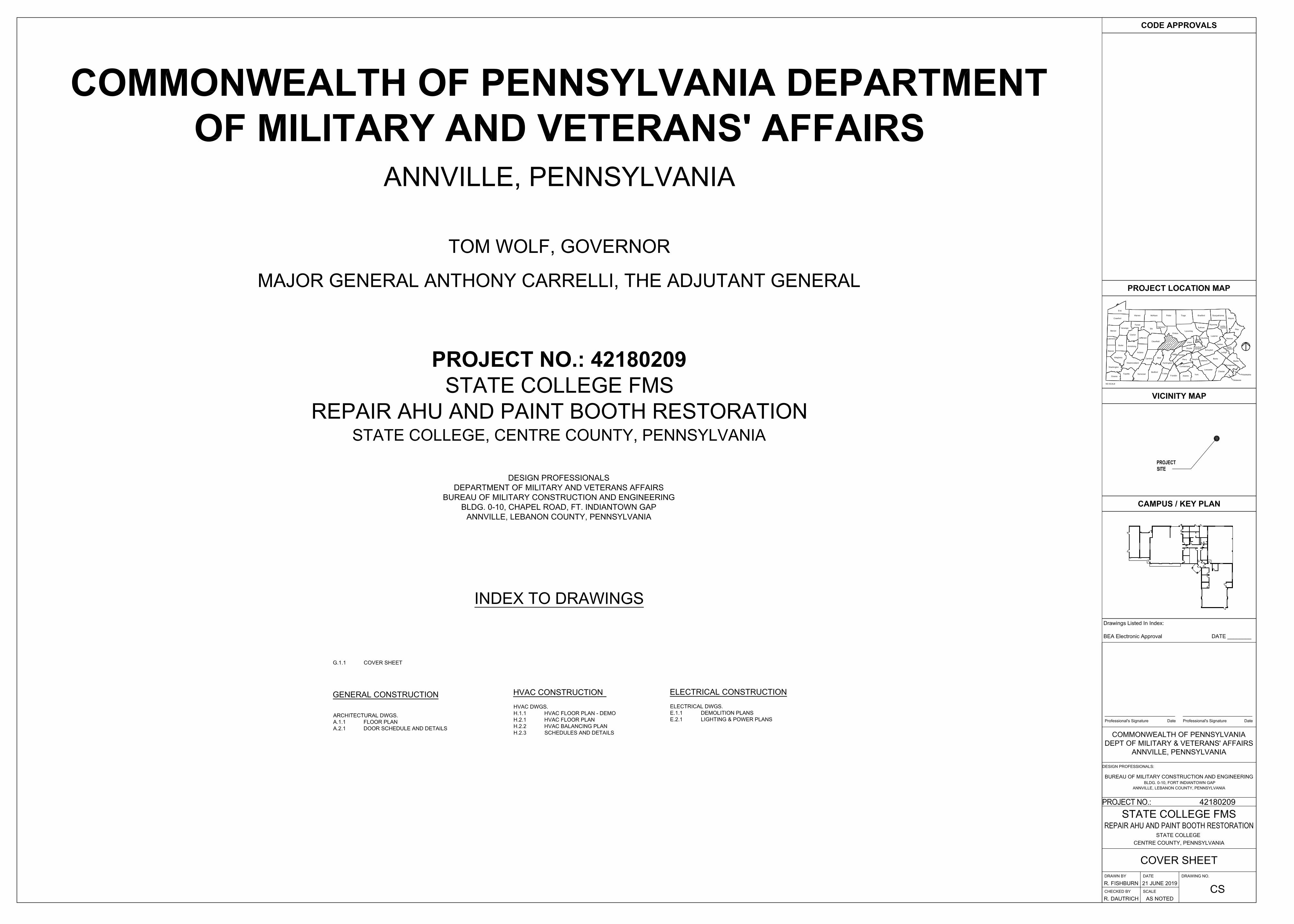
PROJECT MANUAL DMVA PROJECT NO.: 42180209 For REPLACE AHU AND PAINT BOOTH RENOVATION STATE COLLEGE FMS CENTRE COUNTY – STATE COLLEGE – PENNSYLVANIA Tom Wolf, GOVERNOR Date: 21 JUNE, 2019 DEPARTMENT OF MILITARY AND VETERANS AFFAIRS Office of Facilities and Engineering Bureau of Military Construction and Engineering Bldg. 0-10, Chapel Road, Ft. Indiantown Gap Annville, Lebanon County, PA 17003 Phone: (717) 861-2345 FAX: (717) 861-8583
Transcript
PROJECT MANUAL
DMVA PROJECT NO.: 42180209
For
REPLACE AHU AND PAINT BOOTH RENOVATION
STATE COLLEGE FMS CENTRE COUNTY – STATE COLLEGE – PENNSYLVANIA
Tom Wolf, GOVERNOR
Date: 21 JUNE, 2019
DEPARTMENT OF MILITARY AND VETERANS AFFAIRS
Office of Facilities and Engineering Bureau of Military Construction and Engineering
Bldg. 0-10, Chapel Road, Ft. Indiantown Gap Annville, Lebanon County, PA 17003
Phone: (717) 861-2345 FAX: (717) 861-8583
DMVA Project No. 42180209 010100 - 1
SECTION 010100
SUMMARY OF WORK
PART 1 – GENERAL
1.1 STIPULATIONS
A. The specifications sections “General Conditions of the Construction Contract”, “Special
Conditions”, and “Division 1 – General Requirements” form a part of this Section by this
reference thereto and shall have the same force and effect as if printed herewith in full.
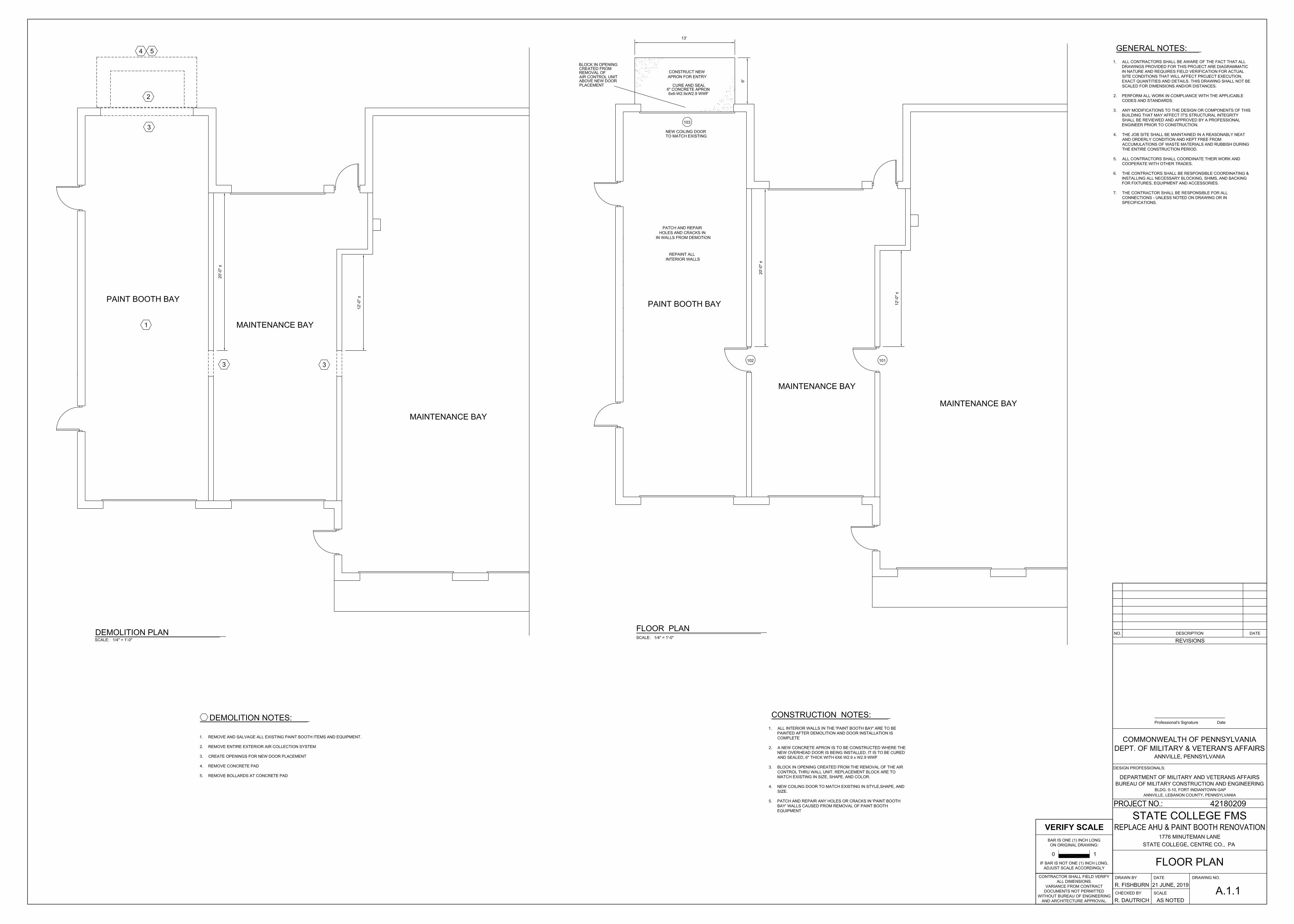
1.2 SCOPE OF WORK, GENERAL
A. The work under this Contract shall generally consist of, but not necessarily limited to,
providing all labor, material, devices, tools and equipment required for the repair of the
AHU system in the FMS and restoration of the Paint Booth, located at State College
FMS, Centre County, Pennsylvania and shall be in total accordance with the
specifications and drawings and subject to the terms and conditions of all other Contract
Documents.
1.3 PERFORMANCE PERIOD
A. Two Hundred Seventy (270) calendar days from Government granted Notice to Proceed.
1.4 WAGE SCALES
A. Wage Scales ARE REQUIRED to be paid on this Project.
1.5 QUESTIONS DURING BID PROCESS
A. Direct all questions pertaining to the project as shown and described in the contract
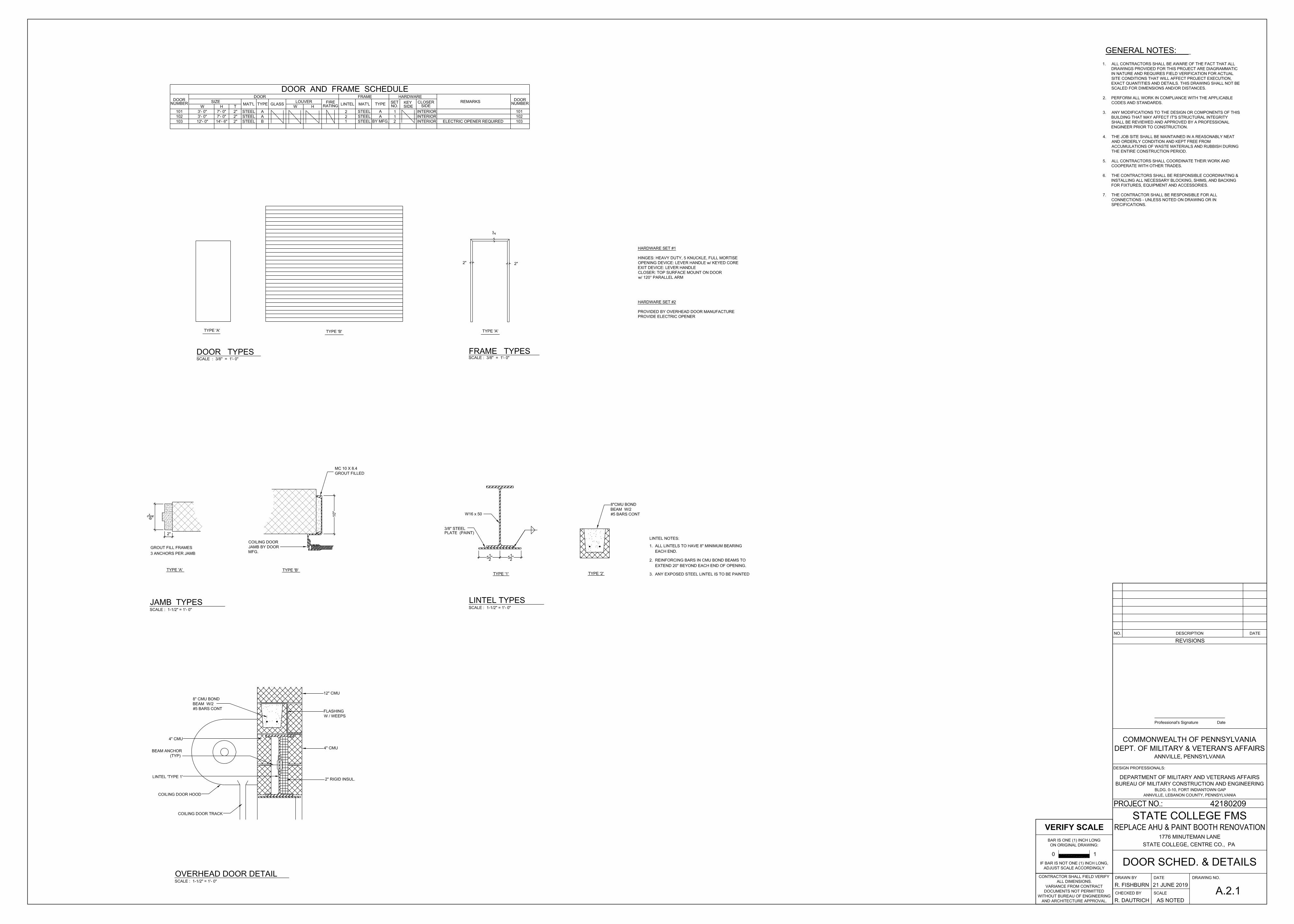
A. Manufacturer's Nameplate: Do not provide manufacturers' products that have manufacturer's
name or trade name displayed in a visible location (omit removable nameplates) except in
conjunction with required fire-rated labels and as otherwise approved by Architect.
1. Manufacturer's identification will be permitted on rim of lock cylinders only.
B. Base Metals: Produce door hardware units of base metal, fabricated by forming method
indicated, using manufacturer's standard metal alloy, composition, temper, and hardness.
Furnish metals of a quality equal to or greater than that of specified door hardware units and
BHMA A156.18 for finishes. Do not furnish manufacturer's standard materials or forming
methods if different from specified standard.
C. Fasteners: Provide door hardware manufactured to comply with published templates generally
prepared for machine, wood, and sheet metal screws. Provide screws according to
commercially recognized industry standards for application intended. Provide Phillips flat-head
screws with finished heads to match surface of door hardware, unless otherwise indicated.
1. Concealed Fasteners: For door hardware units that are exposed when door is closed,
except for units already specified with concealed fasteners. Do not use through bolts for
installation where bolt head or nut on opposite face is exposed unless it is the only means
of securely attaching the door hardware. Where through bolts are used on hollow door
and frame construction, provide sleeves for each through bolt.
2. Steel Machine or Wood Screws: For the following fire-rated applications:
a. Mortise hinges to doors.
b. Strike plates to frames.
c. Closers to doors and frames.
3. Steel Through Bolts: For the following fire-rated applications, unless door blocking is
provided:
a. Closers to doors and frames.
4. Spacers or Sex Bolts: For through bolting of hollow metal doors.
2.27 FINISHES
A. Standard: Comply with BHMA A156.18.
B. Protect mechanical finishes on exposed surfaces from damage by applying a strippable,
temporary protective covering before shipping.
C. Appearance of Finished Work: Variations in appearance of abutting or adjacent pieces are
acceptable if they are within one-half of the range of approved Samples. Noticeable variations
in the same piece are not acceptable. Variations in appearance of other components are
acceptable if they are within the range of approved Samples and are assembled or installed to
minimize contrast.
D. BHMA Designations: Comply with base material and finish requirements indicated by the
following:
DMVA Project No.: 42180209 087111- 15
1. BHMA 600: Primed for painting, over steel base metal.
2. BHMA 605: Bright brass, clear coated, over brass base metal.
3. BHMA 606: Satin brass, clear coated, over brass base metal.
4. BHMA 609: Satin brass, blackened, satin relieved, clear coated, over brass base metal.
5. BHMA 611: Bright bronze, clear coated, over bronze base metal.
6. BHMA 612: Satin bronze, clear coated, over bronze base metal.
7. BHMA 613: Dark-oxidized satin bronze, oil rubbed, over bronze base metal.
8. BHMA 618: Bright nickel plated, clear coated, over brass or bronze base metal.
9. BHMA 619: Satin nickel plated, clear coated, over brass or bronze base metal.
10. BHMA 622: Flat black coated, over brass or bronze base metal.
11. BHMA 623: Light-oxidized statuary bronze, clear coated, over bronze base metal.
12. BHMA 624: Dark-oxidized statuary bronze, clear coated, over bronze base metal.
13. BHMA 625: Bright chromium plated over nickel, over brass or bronze base metal.
14. BHMA 626: Satin chromium plated over nickel, over brass or bronze base metal.
15. BHMA 627: Satin aluminum, clear coated, over aluminum base metal.
16. BHMA 628: Satin aluminum, clear anodized, over aluminum base metal.
17. BHMA 629: Bright stainless steel, over stainless-steel base metal.
18. BHMA 630: Satin stainless steel, over stainless-steel base metal.
19. BHMA 651: Bright chromium plated over nickel, over steel base metal.
20. BHMA 652: Satin chromium plated over nickel, over steel base metal.
21. BHMA 689: Aluminum painted, over any base metal.
22. BHMA 690: Dark bronze painted, over any base metal.
23. BHMA 691: Light bronze painted, over any base metal.
24. BHMA 717: Bright aluminum, uncoated; aluminum base metal.
25. BHMA 718: Satin aluminum, uncoated; aluminum base metal.
26. BHMA 722: Dark-oxidized bronze, oil rubbed, over architectural bronze base metal.
PART 3 - EXECUTION
3.1 EXAMINATION
A. Examine doors and frames, with Installer present, for compliance with requirements for
installation tolerances, labeled fire door assembly construction, wall and floor construction, and
other conditions affecting performance of door hardware.
B. Proceed with installation only after unsatisfactory conditions have been corrected.
3.2 INSTALLATION
A. Mounting Heights: Mount door hardware units at heights indicated in following applicable
publications, unless specifically indicated or required to comply with governing regulations:
B. Install each door hardware item to comply with manufacturer's written instructions. Where
cutting and fitting are required to install door hardware onto or into surfaces that are later to be
painted or finished in another way, coordinate removal, storage, and reinstallation of surface
protective trim units with finishing work specified in Division 9 Sections. Do not install
surface-mounted items until finishes have been completed on substrates involved.
DMVA Project No.: 42180209 087111- 16
1. Set units level, plumb, and true to line and location. Adjust and reinforce attachment
substrates as necessary for proper installation and operation.
2. Drill and countersink units that are not factory prepared for anchorage fasteners. Space
fasteners and anchors according to industry standards.
C. Thresholds: Set thresholds for exterior and acoustical doors in full bed of sealant complying
with requirements specified in Division 7 Section "Joint Sealants."
3.3 FIELD QUALITY CONTROL
A. Independent Architectural Hardware Consultant: Owner will engage a qualified independent
Architectural Hardware Consultant to perform inspections and to prepare inspection reports.
1. Independent Architectural Hardware Consultant will inspect door hardware and state in
each report whether installed work complies with or deviates from requirements,
including whether door hardware is properly installed and adjusted.
3.4 ADJUSTING
A. Initial Adjustment: Adjust and check each operating item of door hardware and each door to
ensure proper operation or function of every unit. Replace units that cannot be adjusted to
operate as intended. Adjust door control devices to compensate for final operation of heating
and ventilating equipment and to comply with referenced accessibility requirements.
1. Door Closers: Adjust sweep period so that, from an open position of 70 degrees, the door
will take at least 3 seconds to move to a point 3 inches from the latch, measured to the
leading edge of the door.
B. Six-Month Adjustment: Approximately six months after date of Substantial Completion,
Installer shall perform the following:
1. Examine and readjust each item of door hardware as necessary to ensure function of
doors, door hardware, and electrified door hardware.
2. Consult with and instruct Owner's personnel on recommended maintenance procedures.
3. Replace door hardware items that have deteriorated or failed due to faulty design,
materials, or installation of door hardware units.
3.5 CLEANING AND PROTECTION
A. Clean adjacent surfaces soiled by door hardware installation.
B. Clean operating items as necessary to restore proper function and finish.
C. Provide final protection and maintain conditions that ensure door hardware is without damage
or deterioration at time of Substantial Completion.
3.6 DEMONSTRATION
DMVA Project No.: 42180209 087111- 17
A. Engage a factory-authorized service representative to train Owner's maintenance personnel to
adjust, operate, and maintain door hardware and door hardware finishes.
END OF SECTION
DMVA Project No.: 42180209 099113-1
SECTION 099113
EXTERIOR PAINTING
PART 1 - GENERAL
1.1 STIPULATIONS
A. The specifications sections “General Conditions of the Construction Contract,” “Special
Conditions,” and “Division 1 – General Requirements” form a part of this Section by this
reference thereto and shall have the same force and effect as if printed herewith in full.
1.2 SUMMARY
A. This Section includes surface preparation and the application of paint systems on the following
exterior substrates:
1. Steel.
2. Hollow Metal Doors / Frames
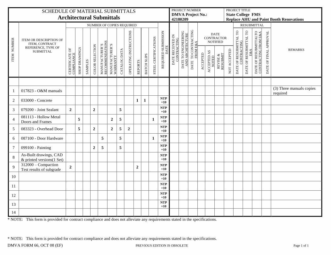
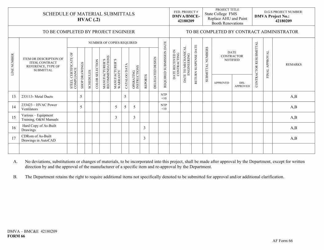
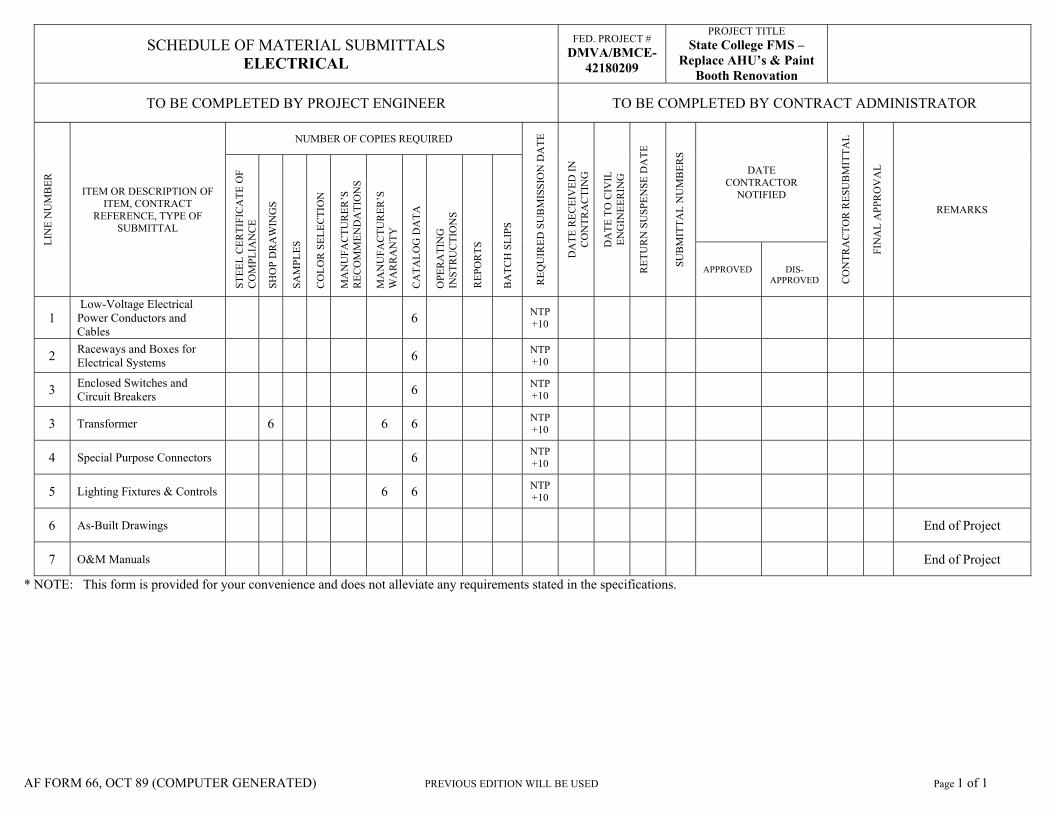
1.3 SUBMITTALS
A. Make submissions in accordance with Division 1 Specifications and ‘SCHEDULE OF
MATERIAL SUBMITTALS’, attached at the end of the Specifications.
B. No deviations, substitutions or changes of materials, to be incorporated into this project, shall be
made after approval by the Department, except for written direction by and the approval of the
manufacturer of a specific item and re-approval by the Department.
C. The Department retains the right to require additional items not specifically denoted to be
submitted for approval and/or additional clarification.
1.4 QUALITY ASSURANCE
A. MPI Standards:
1. Products: Complying with MPI standards indicated and listed in "MPI Approved
Products List."
2. Preparation and Workmanship: Comply with requirements in "MPI Architectural
Painting Specification Manual" for products and paint systems indicated.
1.5 DELIVERY, STORAGE, AND HANDLING
A. Store materials not in use in tightly covered containers in well-ventilated areas with ambient
temperatures continuously maintained at not less than 45 deg F.
1. Maintain containers in clean condition, free of foreign materials and residue.
DMVA Project No.: 42180209 099113-2
2. Remove rags and waste from storage areas daily.
1.6 PROJECT CONDITIONS
A. Apply paints only when temperature of surfaces to be painted and ambient air temperatures are
between 50 and 95 deg F.
B. Do not apply paints when relative humidity exceeds 85 percent; at temperatures less than 5 deg
F above the dew point; or to damp or wet surfaces.
1.7 EXTRA MATERIALS
A. Furnish extra materials described below that are from same production run (batch mix) as
materials applied and that are packaged for storage and identified with labels describing
contents.
1. Quantity: Furnish an additional 5 percent, but not less than 1 gal. of each material and
color applied.
PART 2 - PRODUCTS
2.1 MANUFACTURERS
A. Available Manufacturers: Subject to compliance with requirements, manufacturers offering
products that may be incorporated into the Work include, but are not limited to, the following:
1. M.A.B. Paints.
2. Sherwin-Williams Company (The).
3. Or “Approved Equal.”
2.2 PAINT, GENERAL
A. Material Compatibility:
1. Provide materials for use within each paint system that are compatible with one another
and substrates indicated, under conditions of service and application as demonstrated by
manufacturer, based on testing and field experience.
2. For each coat in a paint system, provide products recommended in writing by
manufacturers of topcoat for use in paint system and on substrate indicated.
B. Colors: As selected by Government Design Professional from manufacturer's full range.
2.3 METAL PRIMERS
A. Alkyd Anticorrosive Metal Primer: MPI #79.
1. VOC Content: E Range of E2.
DMVA Project No.: 42180209 099113-3
B. Quick-Drying Alkyd Metal Primer: MPI #76.
1. VOC Content: E Range of E2.
2.4 EXTERIOR LATEX PAINTS
A. Exterior Latex (Semigloss): MPI #11 (Gloss Level 5).
1. VOC Content: E Range of E2.
PART 3 - EXECUTION
3.1 EXAMINATION
A. Examine substrates and conditions, with Applicator present, for compliance with requirements
for maximum moisture content and other conditions affecting performance of work.
B. Maximum Moisture Content of Substrates: When measured with an electronic moisture meter
as follows:
1. Concrete: 12 percent.
2. Masonry (Clay and CMU): 12 percent.
3. Wood: 15 percent.
4. Plaster: 12 percent.
5. Gypsum Board: 12 percent.
C. Verify suitability of substrates, including surface conditions and compatibility with existing
finishes and primers.
D. Begin coating application only after unsatisfactory conditions have been corrected and surfaces
are dry.
1. Beginning coating application constitutes Contractor's acceptance of substrates and
conditions.
3.2 PREPARATION AND APPLICATION
A. Comply with manufacturer's written instructions and recommendations in "MPI Architectural
Painting Specification Manual" applicable to substrates and paint systems indicated.
B. Clean substrates of substances that could impair bond of paints, including dirt, oil, grease, and
incompatible paints and encapsulants.
1. Remove incompatible primers and reprime substrate with compatible primers as required
to produce paint systems indicated.
C. Apply paints to produce surface films without cloudiness, spotting, holidays, laps, brush marks,
roller tracking, runs, sags, ropiness, or other surface imperfections. Cut in sharp lines and color
breaks.
DMVA Project No.: 42180209 099113-4
D. Protect work of other trades against damage from paint application. Correct damage to work of
other trades by cleaning, repairing, replacing, and refinishing, as approved by Architect, and
leave in an undamaged condition.
E. At completion of construction activities of other trades, touch up and restore damaged or
defaced painted surfaces.
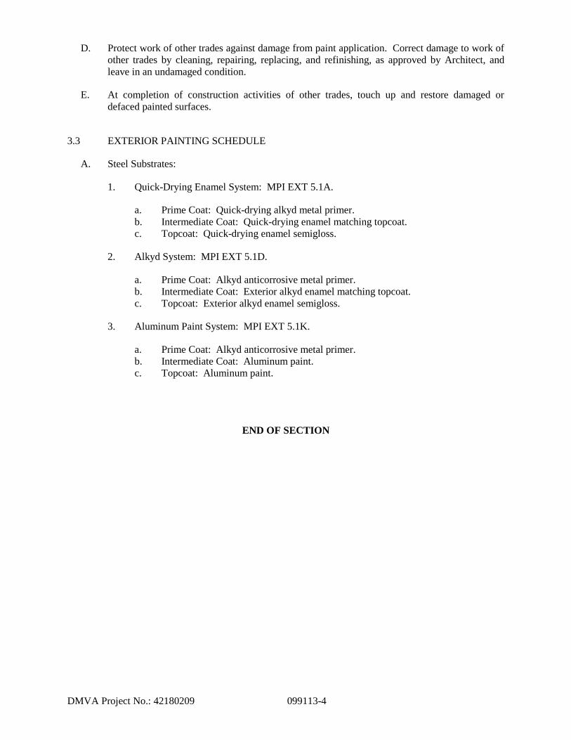
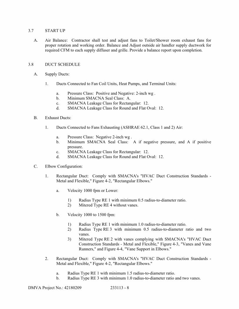
3.3 EXTERIOR PAINTING SCHEDULE
A. Steel Substrates:
1. Quick-Drying Enamel System: MPI EXT 5.1A.
a. Prime Coat: Quick-drying alkyd metal primer.
b. Intermediate Coat: Quick-drying enamel matching topcoat.
c. Topcoat: Quick-drying enamel semigloss.
2. Alkyd System: MPI EXT 5.1D.
a. Prime Coat: Alkyd anticorrosive metal primer.
b. Intermediate Coat: Exterior alkyd enamel matching topcoat.
c. Topcoat: Exterior alkyd enamel semigloss.
3. Aluminum Paint System: MPI EXT 5.1K.
a. Prime Coat: Alkyd anticorrosive metal primer.
b. Intermediate Coat: Aluminum paint.
c. Topcoat: Aluminum paint.
END OF SECTION
DMVA Project No.: 42180209 230130 - 1
SECTION 230130
HVAC AIR-DISTRIBUTION SYSTEM CLEANING
PART 1 - GENERAL
1.1 RELATED DOCUMENTS
A. Drawings and general provisions of the Contract, including General and Supplementary Conditions and Division 01 Specification Sections, apply to this Section.
1.2 SUMMARY
A. Section includes cleaning HVAC air-distribution equipment, ducts, plenums, and system components.
1.3 DEFINITIONS
A. ASCS: Air systems cleaning specialist.
B. NADCA: National Air Duct Cleaners Association.
1.4 INFORMATIONAL SUBMITTALS
A. Qualification Data: For an ASCS.
B. Strategies and procedures plan.
C. Cleanliness verification report.
1.5 QUALITY ASSURANCE
A. ASCS Qualifications: A certified member of NADCA.
1. Certification: Employ an ASCS certified by NADCA on a full-time basis.
B. UL Compliance: Comply with UL 181 and UL 181A for fibrous-glass ducts.
C. Cleaning Conference: Conduct conference at Project site.
1. Review methods and procedures related to HVAC air-distribution system cleaning including, but not limited to, review of the cleaning strategies and procedures plan.
DMVA Project No.: 42180209 230130 - 2
PART 2 - PRODUCTS (Not Used)
PART 3 - EXECUTION
3.1 EXAMINATION
A. Examine HVAC air-distribution equipment, ducts, plenums, and system components to determine appropriate methods, tools, and equipment required for performance of the Work.
B. Perform "Project Evaluation and Recommendation" according to NADCA ACR 2006.
C. Prepare written report listing conditions detrimental to performance of the Work.
D. Proceed with work only after unsatisfactory conditions have been corrected.
3.2 PREPARATION
A. Prepare a written plan that includes strategies and step-by-step procedures. At a minimum, include the following:
1. Supervisor contact information. 2. Work schedule including location, times, and impact on occupied areas. 3. Methods and materials planned for each HVAC component type. 4. Required support from other trades. 5. Equipment and material storage requirements. 6. Exhaust equipment setup locations.
B. Use the existing service openings, as required for proper cleaning, at various points of the HVAC system for physical and mechanical entry and for inspection.
C. Comply with NADCA ACR 2006, "Guidelines for Constructing Service Openings in HVAC Systems" Section.
3.3 CLEANING
A. Comply with NADCA ACR 2006.
B. Remove visible surface contaminants and deposits from within the HVAC system.
C. Systems and Components to Be Cleaned:
1. Air devices for supply and return air. 2. Air-terminal units. 3. Ductwork:
a. Supply-air ducts, including turning vanes, to the air-handling unit. b. Return-air ducts to the air-handling unit. c. Exhaust-air ducts.
DMVA Project No.: 42180209 230130 - 3
4. Air-Handling Units: a. N/A
D. Collect debris removed during cleaning. Ensure that debris is not dispersed outside the HVAC system during the cleaning process.
E. Particulate Collection:
1. For particulate collection equipment, include adequate filtration to contain debris removed. Locate equipment downwind and away from all air intakes and other points of entry into the building.
2. HEPA filtration with 99.97 percent collection efficiency for particles sized 0.3 micrometer or larger shall be used where the particulate collection equipment is exhausting inside the building,
F. Control odors and mist vapors during the cleaning and restoration process.
G. Mark the position of manual volume dampers and air-directional mechanical devices inside the system prior to cleaning. Restore them to their marked position on completion of cleaning.
H. System components shall be cleaned so that all HVAC system components are visibly clean. On completion, all components must be returned to those settings recorded just prior to cleaning operations.
I. Clean all air-distribution devices, registers, grilles, and diffusers.
J. Clean visible surface contamination deposits according to NADCA ACR 2006 and the following:
2. Ensure that a suitable operative drainage system is in place prior to beginning wash-down procedures.
3. Clean evaporator coils, reheat coils, and other airstream components.
K. Duct Systems:
1. Create service openings in the HVAC system as necessary to accommodate cleaning. 2. Mechanically clean duct systems specified to remove all visible contaminants so that the
systems are capable of passing the HVAC System Cleanliness Tests (see NADCA ACR 2006).
L. Debris removed from the HVAC system shall be disposed of according to applicable Federal, state, and local requirements.
M. Mechanical Cleaning Methodology:
1. Source-Removal Cleaning Methods: The HVAC system shall be cleaned using source-removal mechanical cleaning methods designed to extract contaminants from within the HVAC system and to safely remove these contaminants from the facility. No cleaning
DMVA Project No.: 42180209 230130 - 4
method, or combination of methods, shall be used that could potentially damage components of the HVAC system or negatively alter the integrity of the system.
a. Use continuously operating vacuum-collection devices to keep each section being cleaned under negative pressure.
b. Cleaning methods that require mechanical agitation devices to dislodge debris that is adhered to interior surfaces of HVAC system components shall be equipped to safely remove these devices. Cleaning methods shall not damage the integrity of HVAC system components or damage porous surface materials such as duct and plenum liners.
2. Cleaning Mineral-Fiber Insulation Components:
a. Fibrous-glass thermal or acoustical insulation elements present in equipment or ductwork shall be thoroughly cleaned with HEPA vacuuming equipment while the HVAC system is under constant negative pressure and shall not be permitted to get wet according to NADCA ACR 2006.
b. Cleaning methods used shall not cause damage to fibrous-glass components and will render the system capable of passing the HVAC System Cleanliness Test.
c. Fibrous materials that become wet shall be discarded and replaced.
N. Antimicrobial Agents and Coatings:
1. Apply antimicrobial agents and coatings if active fungal growth is reasonably suspected or where unacceptable levels of fungal contamination have been verified. Apply antimicrobial agents and coatings according to manufacturer's written recommendations and EPA registration listing after the removal of surface deposits and debris.
2. When used, antimicrobial treatments and coatings shall be applied after the system is rendered clean.
3. Apply antimicrobial agents and coatings directly onto surfaces of interior ductwork. 4. Sanitizing agent products shall be registered by the EPA as specifically intended for use
in HVAC systems and ductwork.
3.4 CLEANLINESS VERIFICATION
A. Verify cleanliness according to NADCA ACR 2006, "Verification of HVAC System Cleanliness" Section.
B. Verify HVAC system cleanliness after mechanical cleaning and before applying any treatment or introducing any treatment-related substance to the HVAC system, including biocidal agents and coatings.
C. Perform visual inspection for cleanliness. If no contaminants are evident through visual inspection, the HVAC system shall be considered clean. If visible contaminants are evident through visual inspection, those portions of the system where contaminants are visible shall be re-cleaned and subjected to re-inspection for cleanliness.
D. Additional Verification:
1. Perform surface comparison testing or NADCA vacuum test.
DMVA Project No.: 42180209 230130 - 5
2. Conduct NADCA vacuum gravimetric test analysis for nonporous surfaces.
E. Verification of Coil Cleaning: 1. N/A.
F. Prepare a written cleanliness verification report. At a minimum, include the following:
1. Written documentation of the success of the cleaning. 2. Site inspection reports, initialed by supervisor, including notation on areas of inspection,
as verified through visual inspection. 3. Surface comparison test results if required. 4. Gravimetric analysis (nonporous surfaces only). 5. System areas found to be damaged.
3.5 RESTORATION
A. Restore and repair HVAC air-distribution equipment, ducts, plenums, and components.
B. Restore service openings capable of future reopening.
C. Replace fibrous-glass materials that cannot be restored by cleaning or resurfacing.
D. Replace damaged insulation.
E. Ensure that closures do not hinder or alter airflow.
F. New closure materials, including insulation, shall match opened materials and shall have removable closure panels fitted with gaskets and fasteners.
G. Reseal fibrous-glass ducts.
END OF SECTION
DMVA Project No.: 42180209 230500 - 1
SECTION 230500
COMMON WORK RESULTS FOR HVAC
PART 1 - GENERAL
1.1 STIPULATIONS
A. The specifications sections “General Conditions of the Construction Contract”, “Special Conditions”, and “Division 1 – General Requirements” form a part of this Section by this reference thereto, and shall have the same force and effect as if printed herewith in full.
1.2 RELATED DOCUMENTS
A. Drawings and general provisions of the Contract, including General and Supplementary Conditions and Division 01 Specification Sections, apply to this Section.
1.3 SUMMARY
A. This Section includes the following:
1. Piping materials and installation instructions common to most piping systems. 2. Dielectric fittings. 3. Sleeves. 4. Escutcheons. 5. Equipment installation requirements common to equipment sections. 6. Painting and finishing. 7. Supports and anchorages. 8. Cast-in-Place Concrete. 9. Mechanical Demolition.
1.4 DEFINITIONS
A. Finished Spaces: Spaces other than mechanical and electrical equipment rooms, furred spaces, pipe and duct chases, unheated spaces immediately below roof, spaces above ceilings, unexcavated spaces, crawlspaces, and tunnels.
B. Exposed, Interior Installations: Exposed to view indoors. Examples include finished occupied spaces and mechanical equipment rooms.
C. Exposed, Exterior Installations: Exposed to view outdoors or subject to outdoor ambient temperatures and weather conditions. Examples include rooftop locations.
D. Concealed, Interior Installations: Concealed from view and protected from physical contact by building occupants. Examples include above ceilings and chases.
DMVA Project No.: 42180209 230500 - 2
E. Concealed, Exterior Installations: Concealed from view and protected from weather conditions and physical contact by building occupants but subject to outdoor ambient temperatures. Examples include installations within unheated shelters.
F. The following are industry abbreviations for plastic materials:
A. Steel Support Welding: Qualify processes and operators according to AWS D1.1, "Structural Welding Code--Steel."
B. Steel Pipe Welding: Qualify processes and operators according to ASME Boiler and Pressure Vessel Code: Section IX, "Welding and Brazing Qualifications."
1. Comply with provisions in ASME B31 Series, "Code for Pressure Piping." 2. Certify that each welder has passed AWS qualification tests for welding processes
involved and that certification is current.
C. Electrical Characteristics for HVAC Equipment: Equipment of higher electrical characteristics may be furnished provided such proposed equipment is approved in writing and connecting electrical services, circuit breakers, and conduit sizes are appropriately modified. If minimum energy ratings or efficiencies are specified, equipment shall comply with requirements.
1.7 DELIVERY, STORAGE, AND HANDLING
A. Deliver pipes and tubes with factory-applied end caps. Maintain end caps through shipping, storage, and handling to prevent pipe end damage and to prevent entrance of dirt, debris, and moisture.
B. Store plastic pipes protected from direct sunlight. Support to prevent sagging and bending.
DMVA Project No.: 42180209 230500 - 3
1.8 COORDINATION
A. Arrange for pipe spaces, chases, slots, and openings in building structure during progress of construction, to allow for HVAC installations.
B. Coordinate installation of required supporting devices and set sleeves in poured-in-place concrete and other structural components as they are constructed.
PART 2 - PRODUCTS
2.1 MANUFACTURERS
A. In other Part 2 articles where subparagraph titles below introduce lists, the following requirements apply for product selection:
1. Available Manufacturers: Subject to compliance with requirements, manufacturers offering products that may be incorporated into the Work include, but are not limited to, the manufacturers specified.
2.2 PIPE, TUBE, AND FITTINGS
A. Refer to individual Division 23 piping Sections for pipe, tube, and fitting materials and joining methods.
B. Pipe Threads: ASME B1.20.1 for factory-threaded pipe and pipe fittings.
2.3 JOINING MATERIALS
A. Refer to individual Division 23 piping Sections for special joining materials not listed below.
B. Pipe-Flange Gasket Materials: Suitable for chemical and thermal conditions of piping system contents.
1. ASME B16.21, nonmetallic, flat, asbestos-free, 1/8-inch maximum thickness unless thickness or specific material is indicated.
a. Full-Face Type: For flat-face, Class 125, cast-iron and cast-bronze flanges. b. Narrow-Face Type: For raised-face, Class 250, cast-iron and steel flanges.
2. AWWA C110, rubber, flat face, 1/8 inch thick, unless otherwise indicated; and full-face or ring type, unless otherwise indicated.
C. Flange Bolts and Nuts: ASME B18.2.1, carbon steel, unless otherwise indicated.
D. Solder Filler Metals: ASTM B 32, lead-free alloys. Include water-flushable flux according to ASTM B 813.
DMVA Project No.: 42180209 230500 - 4
E. Welding Filler Metals: Comply with AWS D10.12 for welding materials appropriate for wall thickness and chemical analysis of steel pipe being welded.
2.4 DIELECTRIC FITTINGS
A. Description: Combination fitting of copper alloy and ferrous materials with threaded, solder-joint, plain, or weld-neck end connections that match piping system materials.
B. Insulating Material: Suitable for system fluid, pressure, and temperature.
C. Dielectric Unions: Factory-fabricated, union assembly, for 250-psig minimum working pressure at 180 deg F.
1. Manufacturers:
a. Eclipse, Inc. b. Epco Sales, Inc. c. Hart Industries, International, Inc. d. Watts Industries, Inc.; Water Products Div. e. Zurn Industries, Inc.; Wilkins Div. f. Or approved equal.
D. Dielectric Flanges: Factory-fabricated, companion-flange assembly, for 150- or 300-psig minimum working pressure as required to suit system pressures.
1. Manufacturers:
a. Capitol Manufacturing Co. b. Epco Sales, Inc. c. Watts Industries, Inc.; Water Products Div. d. Or approved equal.
E. Dielectric-Flange Kits: Companion-flange assembly for field assembly. Include flanges, full-face- or ring-type neoprene or phenolic gasket, phenolic or polyethylene bolt sleeves, phenolic washers, and steel backing washers.
1. Manufacturers:
a. Advance Products & Systems, Inc. b. Calpico, Inc. c. Pipeline Seal and Insulator, Inc. d. Or approved equal.
2. Separate companion flanges and steel bolts and nuts shall have 150- or 300-psig minimum working pressure where required to suit system pressures.
F. Dielectric Couplings: Galvanized-steel coupling with inert and noncorrosive, thermoplastic lining; threaded ends; and 300-psig minimum working pressure at 225 deg F.
1. Manufacturers:
DMVA Project No.: 42180209 230500 - 5
a. Calpico, Inc. b. Lochinvar Corp. c. Or approved equal.
G. Dielectric Nipples: Electroplated steel nipple with inert and noncorrosive, thermoplastic lining; plain, threaded, or grooved ends; and 300-psig minimum working pressure at 225 deg F.
1. Manufacturers:
a. Perfection Corp. b. Precision Plumbing Products, Inc. c. Victaulic Co. of America. d. Or approved equal.
2.5 SLEEVES
A. Galvanized-Steel Sheet: 0.0239-inch minimum thickness; round tube closed with welded longitudinal joint.
B. Steel Pipe: ASTM A 53, Type E, Grade B, Schedule 40, galvanized, plain ends.
C. Molded PVC: Permanent, with nailing flange for attaching to wooden forms.
D. PVC Pipe: ASTM D 1785, Schedule 40.
2.6 ESCUTCHEONS
A. Description: Manufactured wall and ceiling escutcheons and floor plates, with an ID to closely fit around pipe, tube, and insulation of insulated piping and an OD that completely covers opening.
B. One-Piece, Deep-Pattern Type: Deep-drawn, box-shaped brass with polished chrome-plated finish.
C. One-Piece, Cast-Brass Type: With set screw.
1. Finish: Rough brass.
D. One-Piece, Stamped-Steel Type: With set screw or spring clips and chrome-plated finish.
2.7 GROUT
A. Description: ASTM C 1107, Grade B, nonshrink and nonmetallic, dry hydraulic-cement grout.
1. Characteristics: Post-hardening, volume-adjusting, nonstaining, noncorrosive, nongaseous, and recommended for interior and exterior applications.
A. Normal-Weight Concrete: Prepare design mixes, proportioned according to ACI 301, as follows:
1. Minimum Compressive Strength: 3000 psi at 28 days. 2. Maximum Water-Cementitious Materials Ratio: 0.45. 3. Cementitious Materials: Use fly ash, pozzolan, ground granulated blast-furnace slag, and
silica fume as needed to reduce the total amount of portland cement, which would otherwise be used, by not less than 40 percent.
4. Slump Limit: 4 inches, plus or minus 1 inch. 5. Air Content: Maintain within range permitted by ACI 301 (ACI 301M). Do not allow
air content of trowel-finished floor slabs to exceed 3 percent.
PART 3 - EXECUTION
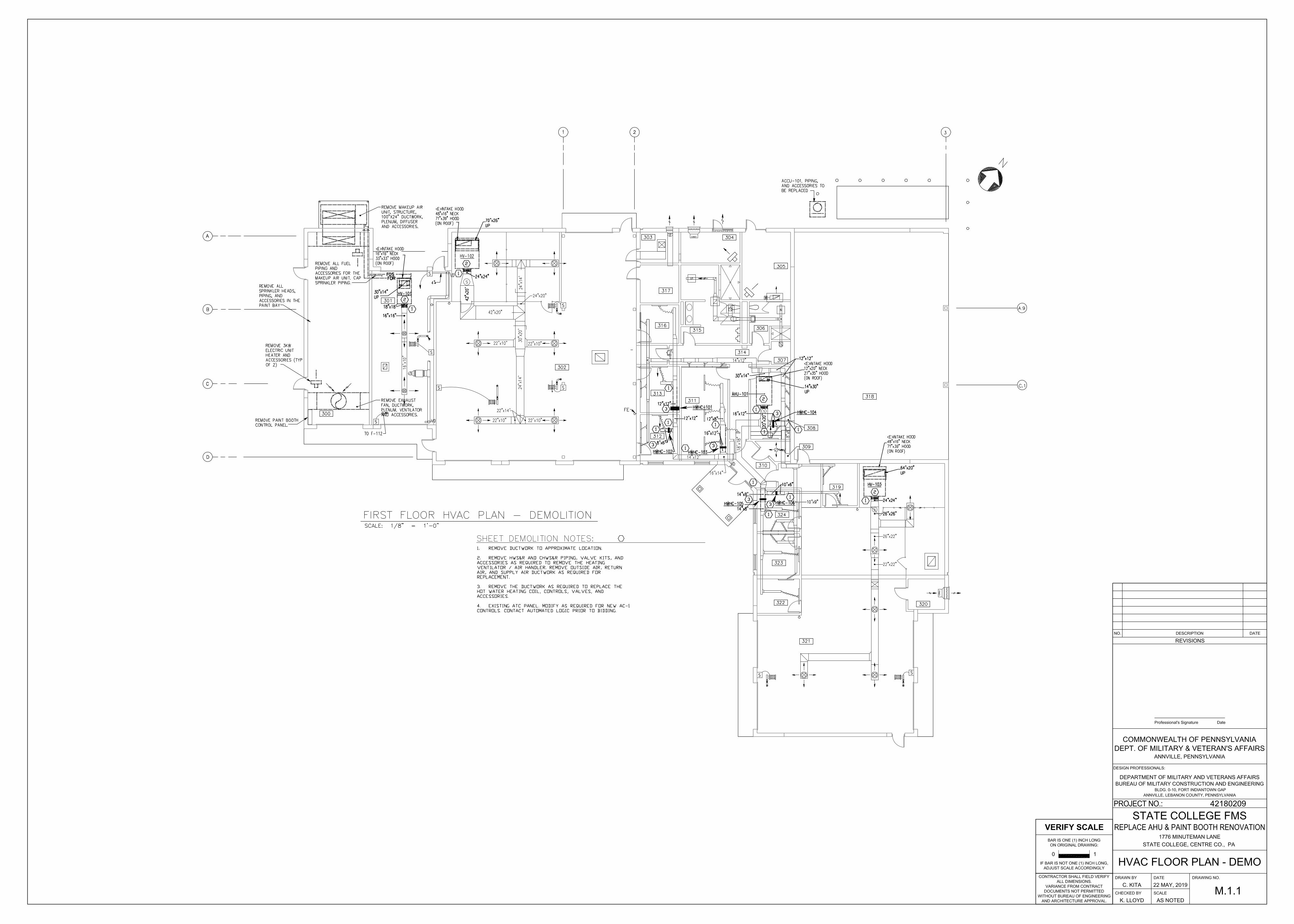
3.1 MECHANICAL DEMOLITION A. Refer to Division 1 Sections “Cutting and Patching” and "Selective Demolition & Restoration"
for general demolition requirements and procedures. B. Disconnect, demolish, and remove mechanical systems, equipment, and components indicated
to be removed. 1. Equipment to Be Removed: Disconnect and cap services and remove equipment. 2. Equipment to Be Removed and Reinstalled: Disconnect and cap services and remove,
clean, and store equipment; when appropriate, reinstall, reconnect, and make equipment operational.
3. Equipment to Be Removed and Salvaged: Disconnect and cap services and remove equipment and deliver to Owner.
C. If pipe, insulation, or equipment to remain is damaged in appearance or is unserviceable,
remove damaged or unserviceable portions and replace with new products of equal capacity and quality.
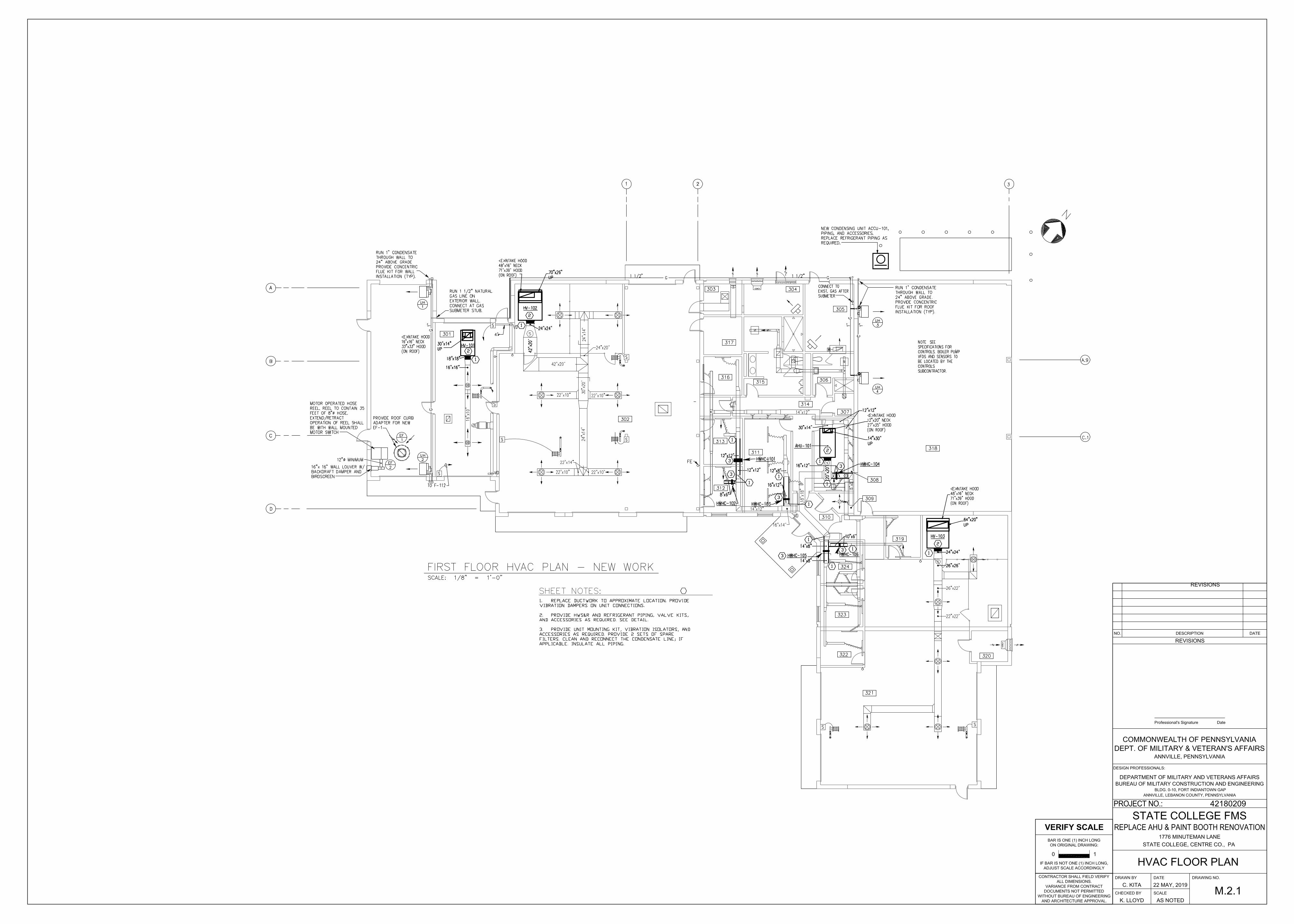
3.2 PIPING SYSTEMS - COMMON REQUIREMENTS
A. Install piping according to the following requirements and Division 23 Sections specifying piping systems.
B. Drawing plans, schematics, and diagrams indicate general location and arrangement of piping systems. Indicated locations and arrangements were used to size pipe and calculate friction loss, expansion, pump sizing, and other design considerations. Install piping as indicated unless deviations to layout are approved on Coordination Drawings.
C. Install piping in concealed locations, unless otherwise indicated and except in equipment rooms and service areas.
DMVA Project No.: 42180209 230500 - 7
D. Install piping indicated to be exposed and piping in equipment rooms and service areas at right angles or parallel to building walls. Diagonal runs are prohibited unless specifically indicated otherwise.
E. Install piping above accessible ceilings to allow sufficient space for ceiling panel removal.
F. Install piping to permit valve servicing.
G. Install piping at indicated slopes.
H. Install piping free of sags and bends.
I. Install fittings for changes in direction and branch connections.
J. Install piping to allow application of insulation.
K. Select system components with pressure rating equal to or greater than system operating pressure.
L. Install escutcheons for penetrations of walls, ceilings, and floors according to the following:
1. New Piping:
a. Piping with Fitting or Sleeve Protruding from Wall: One-piece, deep-pattern type. b. Bare Piping at Wall and Floor Penetrations in Finished Spaces: One-piece, cast-
brass type with polished chrome-plated finish. c. Bare Piping in Equipment Rooms: One-piece, cast-brass type.
M. Sleeves are not required for core-drilled holes.
N. Install sleeves for pipes passing through concrete and masonry walls, gypsum-board partitions, and concrete floor and roof slabs.
1. Cut sleeves to length for mounting flush with both surfaces.
a. Exception: Extend sleeves installed in floors of mechanical equipment areas or other wet areas 2 inches above finished floor level. Extend cast-iron sleeve fittings below floor slab as required to secure clamping ring if ring is specified.
2. Install sleeves in new walls and slabs as new walls and slabs are constructed. 3. Install sleeves that are large enough to provide 1/4-inch annular clear space between
sleeve and pipe or pipe insulation. Use the following sleeve materials:
a. Steel Pipe Sleeves: For pipes smaller than NPS 6. b. Steel Sheet Sleeves: For pipes NPS 6 and larger, penetrating gypsum-board
partitions.
4. Except for underground wall penetrations, seal annular space between sleeve and pipe or pipe insulation, using joint sealants appropriate for size, depth, and location of joint. Refer to Division 07 Section "Joint Sealants" for materials and installation.
DMVA Project No.: 42180209 230500 - 8
O. Fire-Barrier Penetrations: Maintain indicated fire rating of walls, partitions, ceilings, and floors at pipe penetrations. Seal pipe penetrations with firestop materials. Verify final equipment locations for roughing-in.
P. Refer to equipment specifications in other Sections of these Specifications for roughing-in requirements.
3.3 PIPING JOINT CONSTRUCTION
A. Join pipe and fittings according to the following requirements and Division 23 Sections specifying piping systems.
B. Ream ends of pipes and tubes and remove burrs. Bevel plain ends of steel pipe.
C. Remove scale, slag, dirt, and debris from inside and outside of pipe and fittings before assembly.
D. Soldered Joints: Apply ASTM B 813, water-flushable flux, unless otherwise indicated, to tube end. Construct joints according to ASTM B 828 or CDA's "Copper Tube Handbook," using lead-free solder alloy complying with ASTM B 32.
E. Threaded Joints: Thread pipe with tapered pipe threads according to ASME B1.20.1. Cut threads full and clean using sharp dies. Ream threaded pipe ends to remove burrs and restore full ID. Join pipe fittings and valves as follows:
1. Apply appropriate tape or thread compound to external pipe threads unless dry seal threading is specified.
2. Damaged Threads: Do not use pipe or pipe fittings with threads that are corroded or damaged. Do not use pipe sections that have cracked or open welds.
F. Welded Joints: Construct joints according to AWS D10.12, using qualified processes and welding operators according to Part 1 "Quality Assurance" Article.
G. Flanged Joints: Select appropriate gasket material, size, type, and thickness for service application. Install gasket concentrically positioned. Use suitable lubricants on bolt threads.
3.4 PIPING CONNECTIONS
A. Make connections according to the following, unless otherwise indicated:
1. Install unions, in piping NPS 2 and smaller, adjacent to each valve and at final connection to each piece of equipment.
2. Install flanges, in piping NPS 2-1/2 and larger, adjacent to flanged valves and at final connection to each piece of equipment.
3. Wet Piping Systems: Install dielectric coupling and nipple fittings to connect piping materials of dissimilar metals.
DMVA Project No.: 42180209 230500 - 9
3.5 EQUIPMENT INSTALLATION - COMMON REQUIREMENTS
A. Install equipment to allow maximum possible headroom unless specific mounting heights are not indicated.
B. Install equipment level and plumb, parallel and perpendicular to other building systems and components in exposed interior spaces, unless otherwise indicated.
C. Install HVAC equipment to facilitate service, maintenance, and repair or replacement of components. Connect equipment for ease of disconnecting, with minimum interference to other installations. Extend grease fittings to accessible locations.
D. Install equipment to allow right of way for piping installed at required slope.
3.6 PAINTING
A. Damage and Touchup: Repair marred and damaged factory-painted finishes with materials and procedures to match original factory finish.
3.7 ERECTION OF METAL SUPPORTS AND ANCHORAGES
A. Cut, fit, and place miscellaneous metal supports accurately in location, alignment, and elevation to support and anchor HVAC materials and equipment.
B. Field Welding: Comply with AWS D1.1.
3.8 GROUTING
A. Mix and install grout for HVAC equipment base bearing surfaces, pump and other equipment base plates, and anchors.
B. Clean surfaces that will come into contact with grout.
C. Provide forms as required for placement of grout.
D. Avoid air entrapment during placement of grout.
E. Place grout, completely filling equipment bases.
F. Place grout on concrete bases and provide smooth bearing surface for equipment.
G. Place grout around anchors.
H. Cure placed grout.
DMVA Project No.: 42180209 230500 - 10
3.9 CONCRETE PLACEMENT
A. Comply with ACI 301 for placing concrete.
B. Do not add water to concrete during delivery, at Project site, or during placement.
C. Consolidate concrete with mechanical vibrating equipment.
END OF SECTION
DMVA Project No.: 42180209 230510 - 1
SECTION 230510
HVAC ELECTRICAL EQUIPMENT AND WIRING REQUIREMENTS
PART 1 - GENERAL
1.1 STIPULATIONS
A. The specifications sections “General Conditions of the Construction Contract”, “Special Conditions”, and “Division 1 – General Requirements” form a part of this Section by this reference thereto, and shall have the same force and effect as if printed herewith in full.
1.2 RELATED DOCUMENTS
A. Drawings and general provisions of the Contract, including General and Supplementary Conditions and Division 01 Specification Sections, apply to this Section.
1.3 ELECTRICAL EQUIPMENT
A. General:
1. This Contractor shall furnish all motors, starters, disconnects for motors and heating coils and controls for equipment under his Contract, unless otherwise noted.
2. Electrical Contractor shall install all starters, disconnects and overload protectors furnished by this Contractor and shall provide all necessary wire, conduit and boxes to properly connect equipment for this Contractor no matter how many disconnects, starters, etc. are included, unless otherwise noted.
3. This Contractor shall provide all necessary conduit and control wiring to pushbuttons, thermostats, pilot lights, interlocks and similar equipment for this Contractors equipment.
4. Flow control switches, thermostats and similar mechanical-electrical devices necessary for proper operation of mechanical systems shall be furnished and installed by this Contractor.
5. Where the starter and/or safety switch is an integral part of the equipment assembly, the assembly shall be furnished with the wiring complete between starter, controller and motor. The Electrical Contractor will make connections to unit terminals.
6. If motor control center is furnished (and installed) by Electrical Contractor for specific motors, the Mechanical Contractor shall not furnish starters for those specific motors, however the Mechanical Contractor shall furnish Electrical Contractor with starter requirements to insure proper operation of those motors.
7. All motors and motor control equipment and wiring shall meet the requirements of the NEC, and shall comply with the requirements of the Public Utility Company furnishing service and with the rules and regulations of all authorities having jurisdiction.
DMVA Project No.: 42180209 230510 - 2
8. Voltage available at the building is 120/208 volts and 277/480 volts - three phase - four wire (latter preferred).
9. THIS CONTRACTOR SHALL VERIFY VOLTAGE AT SITE BEFORE ORDERING ANY ELECTRICAL EQUIPMENT.
10. The Electrical Contractor shall be responsible for proper rotation of three phase equipment.
PART 2 - PRODUCTS
2.1 CONTROL WIRING
A. All wiring and conduit shall be according to the latest edition of the NEC. All control wiring shall be installed in EMT, applicable portions of the NEC and of "DIVISION 16 - ELECTRICAL".
B. Low voltage control wiring in air plenums shall be a UL approved conductor for application as manufactured by Alpha or Beldon or approved equal.
2.2 STARTERS/DISCONNECTS
A. Starters shall be combination disconnect type.
B. Combination motor starters shall be of the fused switch type complete with magnetic motor starter. Unit shall be of the NEMA Class and size as applicable to motor size, with 3-pole overload. Overload elements and fuses shall be of the proper size to protect the motor. Unless otherwise noted, units shall be equipped with indicating lights, HAND-OFF-AUTOMATIC selector switch, four (4) auxiliary contacts (two N.O. and two N.C.) and fused control transformer to provide 24 volt control voltage.
C. Fusible disconnect switch operating handles shall be interlocked with the door so that the door cannot be opened with the switch in the ON position, except through a hidden release mechanism. The operating handle shall be arranged for padlocking in the OFF position with up to three padlocks. Fuses shall be furnished by this contractor, of size required to comply with NEC. Where R type fuses are indicated, fuse holders shall be provided with rejection clips.
D. The control circuit shall be wired for 24 volt control, using fused individual control transformers. Circuit shall be fused and shall be interrupted when disconnect device is opened.
E. Combination Motor Starter Manufacturer: Except where an item of mechanical equipment must be integrally furnished with a motor starter produced by another manufacturer, provide combination starters for mechanical equipment manufactured by a single one of the following:
1. Allen-Bradley Co.
2. Cutler-Hammer, Inc.
3. General Electric Co.
4. Square D Co.
DMVA Project No.: 42180209 230510 - 3
5. Westinghouse Electric Co.
6. Or approved equal.
F. All starters shall automatically restart if there is a power outage.
G. Reduced voltage starters shall be provided to comply with power company limitations on in rush current. Refer to electrical drawings or power company for limitations. When reduced voltage starters are to be provided, this information must be given to Electrical Contractor and he must include the cost of connecting these starters in his bid.
H. Units shall have NEMA type 1 enclosure (unless noted otherwise) and as required to comply with NEC.
PART 3 - EXECUTION
3.1 CONTROL WIRING
A. Workmanship on all phases of control wiring shall be equal to that of the Electrical Contractor and shall be performed by competent workmen.
B. Horizontal cable runs shall be made level. Vertical cable runs shall be made plumb. Exposed cable runs shall run parallel or perpendicular to walls and ceilings, i.e., no unsightly diagonals or bends.
C. In building equipment spaces, cables may be run along and strapped to the surface of walls using mechanical fasteners with wire ties.
D. Horizontal cable runs shall be supported every 12 inches, and vertical cable runs shall be supported every 24 inches. Cables will be run in a workmanlike manner parallel to the floor with all droops removed by pulling taut but without exceeding the tensile strength of the conductors.
E. Cable runs may not be run along or fastened to: any telephone cable superstructure, including those supported from the ceiling, from the wall, or on top of the telephone equipment frames; any air handling ductwork beyond fifteen feet from the supply or return fan; any fluid or gas piping.
F. Cables shall be concealed unless permission is otherwise solicited from the Professional and granted in writing.
3.2 RESPONSIBILITIES
A. The following is a list of equipment provided by this Contractor and shows both this Contractor's and the Electrical Contractor's responsibility for the furnishing, installing and connection of control, disconnecting and overload equipment.
B. The conditions under Electrical Equipment, General (above) also apply to these paragraphs.
DMVA Project No.: 42180209 230510 - 4
C. Provide to the Electrical Contractor shop drawings, product data, and manufacturer's instructions for equipment furnished under DIVISION 23.
1. Gas Fired Unit Heaters
a. 120 volt, 1 phase. b. Thermal overload switch provided by Electrical Contractor adjacent to the unit. c. Integral thermostat. d. Control transformers shall be provided by this Contractor.
2. Vehicle Bay Exhaust Fans
a. 120 volt, 1 phase. b. Thermal overload / disconnect switch, with pilot light, shall be provided by the
Electrical Contractor. c. Where indicated, light switches, or toggle switches with pilot lights, shall control
fans. In these cases, thermal overload switches shall be provided and installed by the Electrical Contractor adjacent to the fan.
a. 120 volt, 1 phase. b. Combination starter/disconnect switch furnished by this Contractor and installed
by the Electrical Contractor. c. On/Off Control of Fan shall be with pushbutton or toggle switch provided by the
Manufacturer and installed by Electrical Contractor. d. Up/Down Control of Motor Operated Hose Reel shall be with pushbutton or toggle
switch provided by the Manufacturer and installed by Electrical Contractor.
5. Condensing Unit (Outdoor)
a. 208 volt - 1 phase. b. Starters with overload protection shall be furnished and installed by equipment
manufacturer. c. The Electrical Contractor shall furnish and install a fused weatherproof disconnect
switch. d. All wiring to the respective devices in the unit shall be factory installed by the
equipment manufacturer. e. Control transformers with weatherproof enclosure shall be provided and wired by
this Contractor.
END OF SECTION
DMVA Project No.: 42180209 230529 - 1
SECTION 230529
HANGERS AND SUPPORTS FOR HVAC PIPING AND EQUIPMENT
PART 1 - GENERAL
1.1 STIPULATIONS
A. The specifications sections “General Conditions of the Construction Contract”, “Special Conditions”, and “Division 1 – General Requirements” form a part of this Section by this reference thereto, and shall have the same force and effect as if printed herewith in full.
1.2 RELATED DOCUMENTS
A. Drawings and general provisions of the Contract, including General and Supplementary Conditions and Division 01 Specification Sections, apply to this Section.
1.3 SUMMARY
A. Section Includes:
1. Metal pipe hangers and supports. 2. Trapeze pipe hangers. 3. Fastener systems. 4. Equipment supports.
1.4 PERFORMANCE REQUIREMENTS
A. Structural Performance: Hangers and supports for HVAC piping and equipment shall withstand the effects of gravity loads and stresses within limits and under conditions indicated according to ASCE/SEI 7.
1. Design supports for multiple pipes capable of supporting combined weight of supported systems, system contents, and test water.
2. Design equipment supports capable of supporting combined operating weight of supported equipment and connected systems and components.
1.5 SUBMITTALS
A. Product Data: For each type of product indicated.
B. Shop Drawings: Show fabrication and installation details and include calculations for the following; include Product Data for components:
1. Trapeze pipe hangers.
DMVA Project No.: 42180209 230529 - 2
2. Equipment supports. 3. Steel Certication.
PART 2 - PRODUCTS
2.1 METAL PIPE HANGERS AND SUPPORTS
A. Carbon-Steel Pipe Hangers and Supports:
1. Description: MSS SP-58, Types 1 through 58, factory-fabricated components. 2. Galvanized Metallic Coatings: Pre-galvanized or hot dipped. 3. Nonmetallic Coatings: Plastic coating, jacket, or liner. 4. Padded Hangers: Hanger with fiberglass or other pipe insulation pad or cushion to
support bearing surface of piping. 5. Hanger Rods: Continuous-thread rod, nuts, and washer made of carbon steel.
2.2 TRAPEZE PIPE HANGERS
A. Description: MSS SP-69, Type 59, shop- or field-fabricated pipe-support assembly made from structural carbon-steel shapes with MSS SP-58 carbon-steel hanger rods, nuts, saddles, and U-bolts.
2.3 FASTENER SYSTEMS
A. Powder-Actuated Fasteners: Threaded-steel stud, for use in hardened Portland cement concrete with pull-out, tension, and shear capacities appropriate for supported loads and building materials where used.
B. Mechanical-Expansion Anchors: Insert-wedge-type, zinc-coated, stainless- steel anchors, for use in hardened Portland cement concrete; with pull-out, tension, and shear capacities appropriate for supported loads and building materials where used.
2.4 EQUIPMENT SUPPORTS
A. Description: Shop- or field-fabricated equipment support made from structural carbon-steel shapes.
2.5 MISCELLANEOUS MATERIALS
A. Structural Steel: ASTM A 36/A 36M, carbon-steel plates, shapes, and bars; black and galvanized.
B. Grout: ASTM C 1107, factory-mixed and -packaged, dry, hydraulic-cement, non-shrink and nonmetallic grout; suitable for interior and exterior applications.
1. Properties: Non-staining, noncorrosive, and nongaseous.
A. Metal Pipe-Hanger Installation: Comply with MSS SP-69 and MSS SP-89. Install hangers, supports, clamps, and attachments as required to properly support piping from the building structure.
1. Pipes of Various Sizes: Support together and space trapezes for smallest pipe size or install intermediate supports for smaller diameter pipes as specified for individual pipe hangers.
2. Field fabricate from ASTM A 36/A 36M, carbon-steel shapes selected for loads being supported.
B. Fastener System Installation:
1. Install powder-actuated fasteners for use in lightweight concrete or concrete slabs less than 4 inches thick in concrete after concrete is placed and completely cured. Use operators that are licensed by powder-actuated tool manufacturer. Install fasteners according to powder-actuated tool manufacturer's operating manual.
2. Install mechanical-expansion anchors in concrete after concrete is placed and completely cured. Install fasteners according to manufacturer's written instructions.
C. Install hangers and supports complete with necessary attachments, inserts, bolts, rods, nuts, washers, and other accessories.
D. Install lateral bracing with pipe hangers and supports to prevent swaying.
E. Install building attachments within concrete slabs or attach to structural steel. Install additional attachments at concentrated loads, including valves, flanges, and strainers, NPS 2-1/2 and larger and at changes in direction of piping. Install concrete inserts before concrete is placed; fasten inserts to forms and install reinforcing bars through openings at top of inserts.
F. Load Distribution: Install hangers and supports so that piping live and dead loads and stresses from movement will not be transmitted to connected equipment.
G. Pipe Slopes: Install hangers and supports to provide indicated pipe slopes and to not exceed maximum pipe deflections allowed by ASME B31.9 for building services piping.
3.2 EQUIPMENT SUPPORTS
A. Fabricate structural-steel stands to suspend equipment from structure overhead or to support equipment above floor.
B. Provide lateral bracing, to prevent swaying, for equipment supports.
DMVA Project No.: 42180209 230529 - 4
3.3 METAL FABRICATIONS
A. Cut, drill, and fit miscellaneous metal fabrications for trapeze pipe hangers and equipment supports.
3.4 ADJUSTING
A. Hanger Adjustments: Adjust hangers to distribute loads equally on attachments and to achieve indicated slope of pipe.
B. Trim excess length of continuous-thread hanger and support rods to 1-1/2 inches.
3.5 PAINTING
A. Touchup: Clean field welds and abraded areas of shop paint. Paint exposed areas immediately after erecting hangers and supports. Use same materials as used for shop painting. Comply with SSPC-PA 1 requirements for touching up field-painted surfaces.
1. Apply paint by brush or spray to provide a minimum dry film thickness of 2.0 mils.
B. Galvanized Surfaces: Clean welds, bolted connections, and abraded areas and apply galvanizing-repair paint to comply with ASTM A 780.
3.6 HANGER AND SUPPORT SCHEDULE
A. Specific hanger and support requirements are in Sections specifying piping systems and equipment.
B. Comply with MSS SP-69 for pipe-hanger selections and applications that are not specified in piping system Sections.
C. Use hangers and supports with galvanized metallic coatings for piping and equipment that will not have field-applied finish.
D. Use nonmetallic coatings on attachments for electrolytic protection where attachments are in direct contact with copper tubing.
E. Use carbon-steel pipe hangers and supports and metal trapeze pipe hangers and attachments for general service applications.
F. Horizontal-Piping Hangers and Supports: Unless otherwise indicated and except as specified in piping system Sections, install the following types:
1. Adjustable, Steel Clevis Hangers (MSS Type 1): For suspension of non-insulated or insulated, stationary pipes NPS 1/2 to NPS 30.
2. Carbon- or Alloy-Steel, Double-Bolt Pipe Clamps (MSS Type 3): For suspension of pipes NPS 3/4 to NPS 36, requiring clamp flexibility and up to 4 inches of insulation.
3. Adjustable, Steel Band Hangers (MSS Type 7): For suspension of non-insulated, stationary pipes NPS 1/2 to NPS 8.
DMVA Project No.: 42180209 230529 - 5
4. U-Bolts (MSS Type 24): For support of heavy pipes NPS 1/2 to NPS 30. 5. Single-Pipe Rolls (MSS Type 41): For suspension of pipes NPS 1 to NPS 30, from two
rods if longitudinal movement caused by expansion and contraction might occur.
G. Vertical-Piping Clamps: Unless otherwise indicated and except as specified in piping system Sections, install the following types:
1. Extension Pipe or Riser Clamps (MSS Type 8): For support of pipe risers NPS 3/4 to NPS 24.
2. Carbon- or Alloy-Steel Riser Clamps (MSS Type 42): For support of pipe risers NPS 3/4 to NPS 24 if longer ends are required for riser clamps.
H. Hanger-Rod Attachments: Unless otherwise indicated and except as specified in piping system Sections, install the following types:
I. Building Attachments: Unless otherwise indicated and except as specified in piping system Sections, install the following types:
1. Steel or Malleable Concrete Inserts (MSS Type 18): For upper attachment to suspend pipe hangers from concrete ceiling.
2. Top-Beam C-Clamps (MSS Type 19): For use under roof installations with bar-joist construction, to attach to top flange of structural shape.
3. Side-Beam or Channel Clamps (MSS Type 20): For attaching to bottom flange of beams, channels, or angles.
4. Center-Beam Clamps (MSS Type 21): For attaching to center of bottom flange of beams. 5. Welded Beam Attachments (MSS Type 22): For attaching to bottom of beams if loads
are considerable and rod sizes are large. 6. C-Clamps (MSS Type 23): For structural shapes. 7. Welded-Steel Brackets: For support of pipes from below, or for suspending from above
by using clip and rod. Use one of the following for indicated loads:
a. Light (MSS Type 31): 750 lb. b. Medium (MSS Type 32): 1500 lb. c. Heavy (MSS Type 33): 3000 lb.
8. Side-Beam Brackets (MSS Type 34): For sides of steel or wooden beams. 9. Plate Lugs (MSS Type 57): For attaching to steel beams if flexibility at beam is required.
J. Saddles and Shields: Unless otherwise indicated and except as specified in piping system Sections, install the following types:
1. Steel-Pipe-Covering Protection Saddles (MSS Type 39): To fill interior voids with insulation that matches adjoining insulation.
K. Comply with MSS SP-69 for trapeze pipe-hanger selections and applications that are not specified in piping system Sections.
END OF SECTION
DMVA Project No.: 42180209 230548 - 1
SECTION 230548
VIBRATION CONTROLS FOR HVAC PIPING AND EQUIPMENT
PART 1 - GENERAL
1.1 STIPULATIONS
A. The specifications sections “General Conditions of the Construction Contract”, “Special Conditions”, and “Division 1 – General Requirements” form a part of this Section by this reference thereto, and shall have the same force and effect as if printed herewith in full.
1.2 RELATED DOCUMENTS
A. Drawings and general provisions of the Contract, including General and Supplementary Conditions and Division 01 Specification Sections, apply to this Section.
1.3 SUMMARY
A. This Section includes the following:
1. Isolation pads. 2. Spring hangers. 3. Spring hangers with vertical-limit stops.
1.4 SUBMITTALS
A. Product Data: For the following:
1. Include rated load, rated deflection, and overload capacity for each vibration isolation device.
PART 2 - PRODUCTS
2.1 VIBRATION ISOLATORS
A. Available Manufacturers: Subject to compliance with requirements, manufacturers offering products that may be incorporated into the Work include, but are not limited to, the following:
1. Ace Mountings Co., Inc. 2. Amber/Booth Company, Inc. 3. California Dynamics Corporation. 4. Isolation Technology, Inc. 5. Kinetics Noise Control.
DMVA Project No.: 42180209 230548 - 2
6. Mason Industries. 7. Vibration Eliminator Co., Inc. 8. Vibration Isolation. 9. Vibration Mountings & Controls, Inc. 10. Or approved equal.
B. Pads: Arranged in single or multiple layers of sufficient stiffness for uniform loading over pad area, molded with a nonslip pattern and galvanized-steel base-plates, and factory cut to sizes that match requirements of supported equipment.
1. Resilient Material: Oil- and water-resistant neoprene.
C. Spring Hangers: Combination coil-spring and elastomeric-insert hanger with spring and insert in compression.
1. Frame: Steel, fabricated for connection to threaded hanger rods and to allow for a maximum of 30 degrees of angular hanger-rod misalignment without binding or reducing isolation efficiency.
2. Outside Spring Diameter: Not less than 80 percent of the compressed height of the spring at rated load.
3. Minimum Additional Travel: 50 percent of the required deflection at rated load. 4. Lateral Stiffness: More than 80 percent of rated vertical stiffness. 5. Overload Capacity: Support 200 percent of rated load, fully compressed, without
deformation or failure. 6. Elastomeric Element: Molded, oil-resistant rubber or neoprene. Steel-washer-reinforced
cup to support spring and bushing projecting through bottom of frame. 7. Self-centering hanger rod cap to ensure concentricity between hanger rod and support
spring coil.
D. Spring Hangers with Vertical-Limit Stop: Combination coil-spring and elastomeric-insert hanger with spring and insert in compression and with a vertical-limit stop.
1. Frame: Steel, fabricated for connection to threaded hanger rods and to allow for a maximum of 30 degrees of angular hanger-rod misalignment without binding or reducing isolation efficiency.
2. Outside Spring Diameter: Not less than 80 percent of the compressed height of the spring at rated load.
3. Minimum Additional Travel: 50 percent of the required deflection at rated load. 4. Lateral Stiffness: More than 80 percent of rated vertical stiffness. 5. Overload Capacity: Support 200 percent of rated load, fully compressed, without
deformation or failure. 6. Elastomeric Element: Molded, oil-resistant rubber or neoprene. 7. Adjustable Vertical Stop: Steel washer with neoprene washer "up-stop" on lower
threaded rod. 8. Self-centering hanger rod cap to ensure concentricity between hanger rod and support
spring coil.
DMVA Project No.: 42180209 230548 - 3
2.2 FACTORY FINISHES
A. Finish: Manufacturer's standard paint applied to factory-assembled and -tested equipment before shipping.
1. Powder coating on springs and housings. 2. All hardware shall be galvanized. Hot-dip galvanize metal components for exterior use. 3. Baked enamel or powder coat for metal components on isolators for interior use. 4. Color-code or otherwise mark vibration isolation control devices to indicate capacity
range.
PART 3 - EXECUTION
3.1 EXAMINATION
A. Examine areas and equipment to receive vibration isolation control devices for compliance with requirements for installation tolerances and other conditions affecting performance.
B. Examine roughing-in of reinforcement and cast-in-place anchors to verify actual locations before installation.
C. Proceed with installation only after unsatisfactory conditions have been corrected.
3.2 APPLICATIONS
A. Strength of Support: Where not indicated, select sizes of components so strength will be adequate to carry present and future static loads within specified loading limits.
3.3 VIBRATION-CONTROL DEVICE INSTALLATION
A. Comply with requirements in Division 07 Section "Roof Accessories" for installation of roof curbs, equipment supports, and roof penetrations.
B. Equipment Restraints:
1. Install resilient bolt isolation washers on equipment anchor bolts where clearance between anchor and adjacent surface exceeds 0.125 inch.
C. Install cables so they do not bend across edges of adjacent equipment or building structure.
D. Install bushing assemblies for anchor bolts for floor-mounted equipment, arranged to provide resilient media between anchor bolt and mounting hole in concrete base.
E. Install bushing assemblies for mounting bolts for wall-mounted equipment, arranged to provide resilient media where equipment or equipment-mounting channels are attached to wall.
F. Attachment to Structure: If specific attachment is not indicated, anchor bracing to structure at flanges of beams, at upper truss chords of bar joists, or at concrete members.
DMVA Project No.: 42180209 230548 - 4
G. Drilled-in Anchors:
1. Identify position of reinforcing steel and other embedded items prior to drilling holes for anchors. Do not damage existing reinforcing or embedded items during coring or drilling. Notify the structural engineer if reinforcing steel or other embedded items are encountered during drilling. Locate and avoid pre-stressed tendons, electrical and telecommunications conduit, and gas lines.
2. Do not drill holes in concrete or masonry until concrete, mortar, or grout has achieved full design strength.
3. Wedge Anchors: Protect threads from damage during anchor installation. Heavy-duty sleeve anchors shall be installed with sleeve fully engaged in the structural element to which anchor is to be fastened.
4. Adhesive Anchors: Clean holes to remove loose material and drilling dust prior to installation of adhesive. Place adhesive in holes proceeding from the bottom of the hole and progressing toward the surface in such a manner as to avoid introduction of air pockets in the adhesive.
5. Set anchors to manufacturer's recommended torque, using a torque wrench. 6. Install zinc-coated steel anchors for interior and stainless-steel anchors for exterior
applications.
3.4 ADJUSTING
A. Adjust limit stops on restrained spring isolators to mount equipment at normal operating height. After equipment installation is complete, adjust limit stops so they are out of contact during normal operation.
B. Adjust active height of spring isolators.
C. Adjust restraints to permit free movement of equipment within normal mode of operation.
3.5 HVAC VIBRATION-CONTROL DEVICE SCHEDULE
A. Supported Equipment: .
1. Equipment Location: Exterior. 2. Pads:
a. Material: Neoprene. b. Thickness: 0.125inches. c. Number of Pads: One thick.
B. Suspended Equipment: 1. Isolator Type: Spring Hangers with Vertical-Limit Stop. 2. Minimum Deflection: 0.25inches.
END OF SECTION
DMVA Project No.: 42180209 230553 - 1
SECTION 230553
MECHANICAL IDENTIFICATION
PART 1 - GENERAL
1.1 STIPULATIONS
A. The specifications sections “General Conditions of the Construction Contract”, “Special Conditions”, and “Division 1 – General Requirements” form a part of this Section by this reference thereto, and shall have the same force and effect as if printed herewith in full.
1.2 RELATED DOCUMENTS
A. Drawings and general provisions of the Contract, including General and Supplementary Conditions and Division 1 Specification Sections, apply to this Section.
1.3 SUMMARY
A. This Section includes the following mechanical identification materials and their installation:
A. Product Data: For each type of product indicated.
1.5 COORDINATION
A. Coordinate installation of identifying devices with completion of covering and painting of surfaces where devices are to be applied.
PART 2 - PRODUCTS
2.1 EQUIPMENT IDENTIFICATION DEVICES
A. Equipment Nameplates: Engraved, color-coded laminated plastic. Include contact-type, permanent adhesive.
1. Terminology: Match schedules as closely as possible. 2. Data: Equipment Number. 3. Size: 1 x 4 inches for equipment.
DMVA Project No.: 42180209 230553 - 2
2.2 PIPE LABELS
A. General Requirements for Manufactured Pipe Labels: Preprinted, color-coded, with lettering indicating service, and showing flow direction.
B. Pretensioned Pipe Labels: Precoiled, semi rigid plastic formed to partially cover circumference of pipe and to attach to pipe without fasteners or adhesive.
C. Self-Adhesive Pipe Labels: Printed plastic with contact-type, permanent-adhesive backing.
D. Pipe Label Contents: Include identification of piping service using same designations or abbreviations as used on Drawings, pipe size, and an arrow indicating flow direction.
1. Flow-Direction Arrows: Integral with piping system service lettering to accommodate both directions or as separate unit on each pipe label to indicate flow direction.
2. Lettering Size: At least 1-1/2 inches high.
PART 3 - EXECUTION
3.1 APPLICATIONS, GENERAL
A. Products specified are for applications referenced in other Division 23 Sections. If more than single-type material, device, or label is specified for listed applications, selection is Installer's option.
3.2 EQUIPMENT IDENTIFICATION
A. Install and permanently fasten equipment nameplates on each major item of mechanical equipment. Locate nameplates where accessible and visible. Include nameplates for the following general categories of equipment: 1. Air Handler, Heat Pump, Exhaust Fan, Make-Up Air and Energy Recovery Ventilator
equipment.
B. Install equipment markers with permanent adhesive on or near each major item of mechanical equipment. Data required for markers may be included on signs, and markers may be omitted if both are indicated.
1. Letter Size: Minimum 1/4 inch for name of units if viewing distance is less than 24 inches
2. Data: Distinguish among multiple units, indicate operational requirements, indicate safety and emergency precautions, warn of hazards and improper operations, and identify units.
3. Locate markers where accessible and visible.
DMVA Project No.: 42180209 230553 - 3
3.3 PIPE LABEL INSTALLATION
A. Locate pipe labels where piping is exposed or above accessible ceilings in finished spaces; machine rooms; accessible maintenance spaces such as shafts, tunnels and plenums; and exterior exposed locations as follows:
1. Near each valve and control device. 2. Near each branch connection, excluding short takeoffs for fixtures and terminal units.
Where flow pattern is not obvious, mark each pipe at branch. 3. Near penetrations through walls, floors, ceilings, and inaccessible enclosures. 4. At access doors, manholes, and similar access points that permit view of concealed
piping. 5. Near major equipment items and other points of origination and termination. 6. Spaced at maximum intervals of 50 feet along each run. Reduce intervals to 25 feet in
areas of congested piping and equipment. 7. On piping above removable acoustical ceilings. Omit intermediately spaced labels.
B. Pipe Label Color Schedule:
1. Condensate-waste Water Piping:
a. Background Color: Blue. b. Letter Color: White.
2. Heating Water Piping:
a. Background Color: Red. b. Letter Color: White.
3. Refrigerant Piping:
a. Background Color: Green. b. Letter Color: White.
3.4 ADJUSTING
A. Relocate mechanical identification materials and devices that have become visually blocked by other work.
END OF SECTION
DMVA Project No.: 42180209 230593 - 1
SECTION 230593
TESTING, ADJUSTING, AND BALANCING FOR HVAC
PART 1 - GENERAL
1.1 STIPULATIONS
A. The specifications sections “General Conditions of the Construction Contract”, “Special Conditions”, and “Division 1 – General Requirements” form a part of this Section by this reference thereto, and shall have the same force and effect as if printed herewith in full.
1.2 RELATED DOCUMENTS
A. Drawings and general provisions of the Contract, including General and Supplementary Conditions and Division 01 Specification Sections, apply to this Section.
1.3 SUMMARY
A. Section Includes:
1. Balancing Air Systems:
a. Constant-volume air systems.
1.4 DEFINITIONS
A. AABC: Associated Air Balance Council.
B. NEBB: National Environmental Balancing Bureau.
C. TAB: Testing, adjusting, and balancing.
D. TABB: Testing, Adjusting, and Balancing Bureau.
E. TAB Specialist: An entity engaged to perform TAB Work.
1.5 SUBMITTALS
A. Certified TAB reports.
1.6 QUALITY ASSURANCE
A. TAB Contractor Qualifications: Engage a TAB entity certified by NEBB or TABB.
DMVA Project No.: 42180209 230593 - 2
1. TAB Field Supervisor: Employee of the TAB contractor and certified by NEBB or TABB.
2. TAB Technician: Employee of the TAB contractor and who is certified by NEBB or TABB as a TAB technician.
B. Certify TAB field data reports and perform the following:
1. Review field data reports to validate accuracy of data and to prepare certified TAB reports.
2. Certify that the TAB team complied with the approved TAB plan and the procedures specified and referenced in this Specification.
C. TAB Report Forms: Use standard TAB contractor's forms approved by Engineer.
D. Instrumentation Type, Quantity, Accuracy, and Calibration: As described in ASHRAE 111, Section 5, "Instrumentation."
E. ASHRAE Compliance: Applicable requirements in ASHRAE 62.1, Section 7.2.2 – “Air Balancing.”
F. ASHRAE/IESNA Compliance: Applicable requirements in ASHRAE/IESNA 90.1, Section 6.7.2.3 – “System Balancing.”
PART 2 - PRODUCTS (Not Applicable)
PART 3 - EXECUTION
3.1 EXAMINATION
A. Examine the Contract Documents to become familiar with Project requirements and to discover conditions in systems' designs that may preclude proper TAB of systems and equipment.
B. Examine systems for installed balancing devices, such as test ports, gage cocks, thermometer wells, flow-control devices, balancing valves and fittings, and manual volume dampers. Verify that locations of these balancing devices are accessible.
C. Examine the approved submittals for HVAC systems and equipment.
D. Examine design data including HVAC system descriptions, statements of design assumptions for environmental conditions and systems' output, and statements of philosophies and assumptions about HVAC system and equipment controls.
E. Examine ceiling plenums used for supply, or relief air to verify that they meet the leakage class of connected ducts as specified in Division 23 Section Metal Ducts and are properly separated from adjacent areas. Verify that penetrations in plenum walls are sealed and fire-stopped if required.
DMVA Project No.: 42180209 230593 - 3
1. Relate performance data to Project conditions and requirements, including system effects that can create undesired or unpredicted conditions that cause reduced capacities in all or part of a system.
2. Calculate system-effect factors to reduce performance ratings of HVAC equipment when installed under conditions different from the conditions used to rate equipment performance. To calculate system effects for air systems, use tables and charts found in AMCA 201, "Fans and Systems," or in SMACNA's "HVAC Systems - Duct Design." Compare results with the design data and installed conditions.
F. Examine system and equipment installations and verify that field quality-control testing, cleaning, and adjusting specified in individual Sections have been performed.
G. Examine test reports specified in individual system and equipment Sections.
H. Examine HVAC equipment and filters and verify that bearings are greased, belts are aligned and tight, and equipment with functioning controls is ready for operation.
I. Examine operating safety interlocks and controls on HVAC equipment.
J. Report deficiencies discovered before and during performance of TAB procedures. Observe and record system reactions to changes in conditions. Record default set points if different from indicated values.
3.2 PREPARATION
A. Prepare a TAB plan that includes strategies and step-by-step procedures.
B. Complete system-readiness checks and prepare reports. Verify the following:
1. Permanent electrical-power wiring is complete. 2. Automatic temperature-control systems are operational. 3. Equipment and duct access doors are securely closed. 4. Balance, smoke, and fire dampers are open. 5. Isolating and balancing valves are open and control valves are operational. 6. Ceilings are installed in critical areas where air-pattern adjustments are required and
access to balancing devices is provided. 7. Windows and doors can be closed so indicated conditions for system operations can be
met.
3.3 GENERAL PROCEDURES FOR TESTING AND BALANCING
A. Perform testing and balancing procedures on each system according to the procedures contained in NEBB's "Procedural Standards for Testing, Adjusting, and Balancing of Environmental Systems" SMACNA's "HVAC Systems - Testing, Adjusting, and Balancing" and in this Section.
1. Comply with requirements in ASHRAE 62.1-2004, Section 7.2.2, "Air Balancing."
DMVA Project No.: 42180209 230593 - 4
B. Cut insulation, ducts, pipes, and equipment cabinets for installation of test probes to the minimum extent necessary for TAB procedures.
1. After testing and balancing, patch probe holes in ducts with same material and thickness as used to construct ducts.
2. Install and join new insulation that matches removed materials. Restore insulation, coverings, vapor barrier, and finish according to Division 23 Section "HVAC Insulation."
C. Mark equipment and balancing devices, including damper-control positions, valve position indicators, fan-speed-control levers, and similar controls and devices, with paint or other suitable, permanent identification material to show final settings.
D. Take and report testing and balancing measurements in inch-pound (IP) units.
3.4 GENERAL PROCEDURES FOR BALANCING AIR SYSTEMS
A. Prepare test reports for both fans and outlets. Obtain manufacturer's outlet factors and recommended testing procedures. Crosscheck the summation of required outlet volumes with required fan volumes.
B. Prepare schematic diagrams of systems' "as-built" duct layouts.
C. Determine the best locations in main and branch ducts for accurate duct-airflow measurements.
D. Check airflow patterns from the outdoor-air louvers and dampers and the return- and exhaust-air dampers through the supply-fan discharge and mixing dampers.
E. Locate start-stop and disconnect switches, electrical interlocks, and motor starters.
F. Verify that motor starters are equipped with properly sized thermal protection.
G. Check dampers for proper position to achieve desired airflow path.
H. Check for airflow blockages.
I. Check condensate drains for proper connections and functioning.
J. Check for proper sealing of air-handling-unit components.
K. Verify that air duct system is sealed as specified in Division 23 Section "Metal Ducts."
3.5 PROCEDURES FOR CONSTANT-VOLUME AIR SYSTEMS
A. Adjust fans to deliver total indicated airflows within the maximum allowable fan speed listed by fan manufacturer.
1. Measure total airflow.
DMVA Project No.: 42180209 230593 - 5
a. Where sufficient space in ducts is unavailable for Pitot-tube traverse measurements, measure airflow at terminal outlets and inlets and calculate the total airflow.
2. Measure fan static pressures as follows to determine actual static pressure:
a. Measure outlet static pressure as far downstream from the fan as practical and upstream from restrictions in ducts such as elbows and transitions.
b. Measure static pressure directly at the fan outlet or through the flexible connection. c. Measure inlet static pressure of single-inlet fans in the inlet duct as near the fan as
possible, upstream from the flexible connection, and downstream from duct restrictions.
d. Measure inlet static pressure of double-inlet fans through the wall of the plenum that houses the fan.
3. Measure static pressure across each component that makes up an air-handling unit, rooftop unit, and other air-handling and -treating equipment.
a. Report the cleanliness status of filters and the time static pressures are measured. 4. Review Record Documents to determine variations in design static pressures versus
actual static pressures. Calculate actual system-effect factors. Recommend adjustments to accommodate actual conditions.
5. Obtain approval from engineer for adjustment of fan speed higher or lower than indicated speed. Comply with requirements in Division 23 Sections for air-handling units for adjustment of fans, belts, and pulley sizes to achieve indicated air-handling-unit performance.
6. Do not make fan-speed adjustments that result in motor overload. Consult equipment manufacturers about fan-speed safety factors. Modulate dampers and measure fan-motor amperage to ensure that no overload will occur. Measure amperage in full-cooling, full-heating, economizer, and any other operating mode to determine the maximum required brake horsepower.
B. Adjust volume dampers for main duct, submain ducts, and major branch ducts to indicated airflows within specified tolerances.
1. Measure airflow of submain and branch ducts.
a. Where sufficient space in submain and branch ducts is unavailable for Pitot-tube traverse measurements, measure airflow at terminal outlets and inlets and calculate the total airflow for that zone.
2. Measure static pressure at a point downstream from the balancing damper, and adjust volume dampers until the proper static pressure is achieved.
3. Remeasure each submain and branch duct after all have been adjusted. Continue to adjust submain and branch ducts to indicated airflows within specified tolerances.
C. Measure air outlets and inlets without making adjustments.
1. Measure terminal outlets using a direct-reading hood or outlet manufacturer's written instructions and calculating factors.
DMVA Project No.: 42180209 230593 - 6
D. Adjust air outlets and inlets for each space to indicated airflows within specified tolerances of indicated values. Make adjustments using branch volume dampers rather than extractors and the dampers at air terminals.
1. Adjust each outlet in same room or space to within specified tolerances of indicated quantities without generating noise levels above the limitations prescribed by the Contract Documents.
2. Adjust patterns of adjustable outlets for proper distribution without drafts.
3.6 PROCEDURES FOR MOTORS
A. Motors, 1/2 HP and Larger: Test at final balanced conditions and record the following data:
1. Manufacturer's name, model number, and serial number. 2. Motor horsepower rating. 3. Motor rpm. 4. Efficiency rating. 5. Nameplate and measured voltage, each phase. 6. Nameplate and measured amperage, each phase. 7. Starter thermal-protection-element rating.
B. Motors Driven by Variable-Frequency Controllers: Test for proper operation at speeds varying from minimum to maximum. Test the manual bypass of the controller to prove proper operation. Record observations including name of controller manufacturer, model number, serial number, and nameplate data.
3.7 PROCEDURES FOR CONDENSING UNITS
A. Verify proper rotation of fans.
B. Measure entering- and leaving-air temperatures.
C. Record compressor data.
3.8 TOLERANCES
A. Set HVAC system's air flow rates and water flow rates within the following tolerances:
1. Supply, Return, and Exhaust Fans and Equipment with Fans: Plus or minus 10 percent. 2. Air Outlets and Inlets: Plus or minus 10 percent. 3. Heating-Water Flow Rate: Plus or minus 10 percent.
3.9 REPORTING
A. Initial Construction-Phase Report: Based on examination of the Contract Documents as specified in "Examination" Article, prepare a report on the adequacy of design for systems' balancing devices. Recommend changes and additions to systems' balancing devices to facilitate proper performance measuring and balancing. Recommend changes and additions to
DMVA Project No.: 42180209 230593 - 7
HVAC systems and general construction to allow access for performance measuring and balancing devices.
3.10 FINAL REPORT
A. General: Prepare a certified written report; tabulate and divide the report into separate sections for tested systems and balanced systems.
1. Include a certification sheet at the front of the report's binder, signed and sealed by the certified testing and balancing engineer.
2. Include a list of instruments used for procedures, along with proof of calibration.
B. Final Report Contents: In addition to certified field-report data, include the following: 1. Fan curves. 2. Manufacturers' test data. 3. Field test reports prepared by system and equipment installers. 4. Other information relative to equipment performance; do not include Shop Drawings and
product data.
C. General Report Data: In addition to form titles and entries, include the following data:
1. Title page. 2. Name and address of the TAB contractor. 3. Project name. 4. Project location. 5. Architect's name and address. 6. Engineer's name and address. 7. Contractor's name and address. 8. Report date. 9. Signature of TAB supervisor who certifies the report. 10. Table of Contents with the total number of pages defined for each section of the report.
Number each page in the report. 11. Summary of contents including the following:
a. Indicated versus final performance. b. Notable characteristics of systems. c. Description of system operation sequence if it varies from the Contract
Documents.
12. Nomenclature sheets for each item of equipment. 13. Data for terminal units, including manufacturer's name, type, size, and fittings. 14. Notes to explain why certain final data in the body of reports vary from indicated values. 15. Test conditions for fans and pump performance forms including the following:
a. Settings for outdoor-, return-, and exhaust-air dampers. b. Conditions of filters. c. Cooling coil, wet- and dry-bulb conditions. d. Face and bypass damper settings at coils. e. Fan drive settings including settings and percentage of maximum pitch diameter. f. Inlet vane settings for variable-air-volume systems.
DMVA Project No.: 42180209 230593 - 8
g. Settings for supply-air, static-pressure controller. h. Other system operating conditions that affect performance.
D. System Diagrams: Include schematic layouts of air and hydronic distribution systems. Present each system with single-line diagram and include the following:
1. Quantities of outdoor, supply, return, and exhaust airflows. 2. Duct, outlet, and inlet sizes. 3. Pipe and valve sizes and locations. 4. Terminal units. 5. Balancing stations. 6. Position of balancing devices.
END OF SECTION
DMVA Project No.: 42180209 230713 - 1
SECTION 230713
HVAC DUCT INSULATION
PART 1 - GENERAL
1.1 STIPULATIONS
A. The specifications sections “General Conditions of the Construction Contract”, “Special Conditions”, and “Division 1 – General Requirements” form a part of this Section by this reference thereto, and shall have the same force and effect as if printed herewith in full.
1.2 RELATED DOCUMENTS
A. Drawings and general provisions of the Contract, including General and Supplementary Conditions and Division 01 Specification Sections, apply to this Section.
1.3 SUMMARY
A. Section includes insulating the following duct services: 1. Indoor, exposed supply. 2. Indoor, exposed return. 3. Indoor, concealed exhaust. 4. Indoor, exposed exhaust.
1.4 SUBMITTALS
A. Product Data: For each type of product indicated.
B. Shop Drawings.
1. Detail insulation application at elbows, fittings, dampers, specialties and flanges for each type of insulation.
2. Detail application of field-applied jackets.
C. Field quality-control reports.
1.5 QUALITY ASSURANCE
A. Surface-Burning Characteristics: For insulation and related materials, as determined by testing identical products according to ASTM E 84, by a testing agency acceptable to authorities having jurisdiction. Factory label insulation and jacket materials and adhesive, mastic, tapes, and cement material containers, with appropriate markings of applicable testing agency.
DMVA Project No.: 42180209 230713 - 2
1. Insulation Installed Indoors: Flame-spread index of 25 or less, and smoke-developed index of 50 or less.
PART 2 - PRODUCTS
2.1 INSULATION MATERIALS
A. Comply with requirements in "Duct Insulation Schedule, General," "Indoor Duct and Plenum Insulation Schedule," and "Aboveground, Outdoor Duct and Plenum Insulation Schedule" articles for where insulating materials shall be applied.
B. Products shall not contain asbestos, lead, mercury, or mercury compounds.
C. Foam insulation materials shall not use CFC or HCFC blowing agents in the manufacturing process.
D. Mineral-Fiber Blanket Insulation: Mineral or glass fibers bonded with a thermosetting resin and wrapped with a factory-applied FSK or ASJ jacket. Factory-applied jacket requirements are specified in "Factory-Applied Jackets" Article.
1. Products: Subject to compliance with requirements, provide one of the following:
a. CertainTeed Corp.; SoftTouch Duct Wrap. b. Johns Manville; Microlite. c. Knauf Insulation; Friendly Feel Duct Wrap. d. Manson Insulation Inc.; Alley Wrap. e. Owens Corning; SOFTR All-Service Duct Wrap. f. Or approved equal.
2.2 TAPES
A. ASJ Tape: White, Paintable, vapor-retarder tape matching factory-applied jacket with acrylic adhesive, complying with ASTM C 1136.
1. Products: Subject to compliance with requirements, provide one of the following:
a. ABI, Ideal Tape Division; 428 AWF ASJ. b. Avery Dennison Corporation, Specialty Tapes Division; Fasson 0836. c. Compac Corporation; 104 and 105. d. Venture Tape; 1540 CW Plus, 1542 CW Plus, and 1542 CW Plus/SQ.
A. Fire-Rated Blanket: High-temperature, flexible, blanket insulation with FSK jacket that is tested and certified to provide a 2-hour fire rating by an NRTL acceptable to authorities having jurisdiction.
2.4 ADHESIVES
A. Materials shall be compatible with insulation materials, jackets, and substrates and for bonding insulation to itself and to surfaces to be insulated unless otherwise indicated.
B. Mineral-Fiber Adhesive: Comply with MIL-A-3316C, Class 2, Grade A.
2.5 MASTICS
A. Materials shall be compatible with insulation materials, jackets, and substrates; comply with MIL-PRF-19565C, Type II.
1. For indoor applications, use mastics that have a VOC content of 50 g/L or less when calculated according to 40 CFR 59, Subpart D (EPA Method 24).
DMVA Project No.: 42180209 230713 - 4
B. Vapor-Barrier Mastic: Water based; suitable for indoor use on below ambient services.
1. Products: Subject to compliance with requirements, available products that may be incorporated into the Work include, but are not limited to, the following:
a. Foster Brand, Specialty Construction Brands, Inc., a business of H. B. Fuller Company; 30-80/30-90.
b. Vimasco Corporation; 749.
2. Water-Vapor Permeance: ASTM E 96/E 96M, Procedure B, 0.013 perm at 43-mil dry film thickness.
3. Service Temperature Range: Minus 20 to plus 180 deg F. 4. Solids Content: ASTM D 1644, 58 percent by volume and 70 percent by weight. 5. Color: White.
2.6 SEALANTS
A. FSK and Metal Jacket Flashing Sealants:
1. Materials shall be compatible with insulation materials, jackets, and substrates. 2. Fire- and water-resistant, flexible, elastomeric sealant. 3. Service Temperature Range: Minus 40 to plus 250 deg F. 4. Color: Aluminum.
B. ASJ Flashing Sealants:
1. Materials shall be compatible with insulation materials, jackets, and substrates. 2. Fire- and water-resistant, flexible, elastomeric sealant. 3. Service Temperature Range: Minus 40 to plus 250 deg F. 4. Color: White, Paintable.
2.7 FACTORY-APPLIED JACKETS
A. Insulation system schedules indicate factory-applied jackets on various applications. When factory-applied jackets are indicated, comply with the following:
1. ASJ: White, Paintable, kraft-paper, fiberglass-reinforced scrim with aluminum-foil backing; complying with ASTM C 1136, Type I.
2. FSK Jacket: Aluminum-foil, fiberglass-reinforced scrim with kraft-paper backing; complying with ASTM C 1136, Type II.
2.8 SECUREMENTS
A. Aluminum Bands: ASTM B 209, Alloy 3003, 3005, 3105, or 5005; Temper H-14, 0.020 inch thick, 1/2 inch wide with wing seal or closed seal.
1. Products: Subject to compliance with requirements, provide one of the following:
a. ITW Insulation Systems; Gerrard Strapping and Seals.
DMVA Project No.: 42180209 230713 - 5
b. RPR Products, Inc.; Insul-Mate Strapping, Seals, and Springs.
PART 3 - EXECUTION
3.1 PREPARATION
A. Surface Preparation: Clean and dry surfaces to receive insulation. Remove materials that will adversely affect insulation application.
3.2 GENERAL INSTALLATION REQUIREMENTS
A. Install insulation materials, accessories, and finishes with smooth, straight, and even surfaces; free of voids throughout the length of ducts and fittings.
B. Install insulation materials, vapor barriers or retarders, jackets, and thicknesses required for each item of duct system as specified in insulation system schedules.
C. Install accessories compatible with insulation materials and suitable for the service. Install accessories that do not corrode, soften, or otherwise attack insulation or jacket in either wet or dry state.
D. Install insulation with longitudinal seams at top and bottom of horizontal runs.
E. Install multiple layers of insulation with longitudinal and end seams staggered.
F. Keep insulation materials dry during application and finishing.
G. Install insulation with tight longitudinal seams and end joints. Bond seams and joints with adhesive recommended by insulation material manufacturer.
H. Install insulation with least number of joints practical.
I. Where vapor barrier is indicated, seal joints, seams, and penetrations in insulation at hangers, supports, anchors, and other projections with vapor-barrier mastic.
1. Install insulation continuously through hangers and around anchor attachments. 2. For insulation application where vapor barriers are indicated, extend insulation on anchor
legs from point of attachment to supported item to point of attachment to structure. Taper and seal ends at attachment to structure with vapor-barrier mastic.
3. Install insert materials and install insulation to tightly join the insert. Seal insulation to insulation inserts with adhesive or sealing compound recommended by insulation material manufacturer.
J. Install insulation with factory-applied jackets as follows:
1. Draw jacket tight and smooth. 2. Cover circumferential joints with 3-inch-wide strips, of same material as insulation
jacket. Secure strips with adhesive and outward clinching staples along both edges of strip, spaced 4 inches o.c.
DMVA Project No.: 42180209 230713 - 6
3. Overlap jacket longitudinal seams at least 1-1/2 inches. Clean and dry surface to receive self-sealing lap. Staple laps with outward clinching staples along edge at 4 inches o.c.
a. For below ambient services, apply vapor-barrier mastic over staples.
4. Cover joints and seams with tape, according to insulation material manufacturer's written instructions, to maintain vapor seal.
5. Where vapor barriers are indicated, apply vapor-barrier mastic on seams and joints and at ends adjacent to duct flanges and fittings.
K. Cut insulation in a manner to avoid compressing insulation more than 75 percent of its nominal thickness.
L. Finish installation with systems at operating conditions. Repair joint separations and cracking due to thermal movement.
M. Repair damaged insulation facings by applying same facing material over damaged areas. Extend patches at least 4 inches beyond damaged areas. Adhere, staple, and seal patches similar to butt joints.
3.3 PENETRATIONS
A. Insulation Installation at roof Penetrations: Install insulation continuously through roof penetrations.
1. Seal penetrations with flashing sealant. 2. For applications requiring only indoor insulation, terminate insulation above roof surface
and seal with joint sealant. For applications requiring indoor insulation, install insulation applications tightly joined to indoor insulation ends. Seal joint with joint sealant.
B. Insulation Installation at Interior Wall and Partition Penetrations (That Are Not Fire Rated): Install insulation continuously through walls and partitions.
C. Insulation Installation at Floor Penetrations:
1. Duct: For penetrations through fire-rated assemblies, terminate insulation at fire damper sleeves and externally insulate damper sleeve beyond floor to match adjacent duct insulation. Overlap damper sleeve and duct insulation at least 2 inches.
2. Seal penetrations through fire-rated assemblies.
3.4 INSTALLATION OF MINERAL-FIBER INSULATION
A. Blanket Insulation Installation on Ducts and Plenums: Secure with adhesive and insulation pins. 1. Apply adhesive to entire circumference of ducts and to all surfaces of fittings and
transitions. 2. Install either capacitor-discharge-weld pins and speed washers or cupped-head, capacitor-
discharge-weld pins on sides and bottom of horizontal ducts and sides of vertical ducts as follows:
DMVA Project No.: 42180209 230713 - 7
a. On duct sides with dimensions 18 inches and smaller, place pins along longitudinal centerline of duct. Space 3 inches maximum from insulation end joints, and 16 inches o.c.
b. On duct sides with dimensions larger than 18 inches, place pins 16 inches o.c. each way and 3 inches maximum from insulation joints. Install additional pins to hold insulation tightly against surface at cross bracing.
c. Pins may be omitted from top surface of horizontal, rectangular ducts and plenums. d. Do not over compress insulation during installation. e. Impale insulation over pins and attach speed washers. f. Cut excess portion of pins extending beyond speed washers or bend parallel with
insulation surface. Cover exposed pins and washers with tape matching insulation facing.
3.5 FINISHES
A. Insulation with ASJ or Other Paintable Jacket Material: Paint jacket with paint system identified below and as specified in Division 09 painting Sections.
1. Flat Acrylic Finish: Two finish coats over a primer that is compatible with jacket material and finish coat paint. Add fungicidal agent to render fabric mildew proof.
a. Finish Coat Material: Interior, flat, latex-emulsion size.
B. Color: Final color as selected by Government Design Professional from manufacturer's full range. Vary first and second coats to allow visual inspection of the completed Work.
C. Do not field paint aluminum or stainless-steel jackets.
3.6 FIELD QUALITY CONTROL
A. All insulation applications will be considered defective Work if sample inspection reveals noncompliance with requirements.
3.7 DUCT INSULATION SCHEDULE, GENERAL
A. Plenums and Ducts Requiring Insulation with ASJ or other paintable jacket material:
1. Indoor, exposed supply.
B. Plenums and Ducts Requiring Insulation with FSK jacket material:
A. Supply-Air Duct and Plenum Insulation: Mineral-fiber blanket, R-5 minimum.
DMVA Project No.: 42180209 230713 - 8
B. Outdoor-Air Duct and Plenum Insulation: Mineral-fiber blanket, R-5 minimum.
C. Exhaust-Air Duct and Plenum Insulation: Mineral-fiber blanket, R-5 minimum.
END OF SECTION
DMVA Project No.: 42180209 230719 - 1
SECTION 230719
HVAC PIPING INSULATION
PART 1 - GENERAL
1.1 STIPULATIONS
A. The specifications sections “General Conditions of the Construction Contract”, “Special Conditions”, and “Division 1 – General Requirements” form a part of this Section by this reference thereto, and shall have the same force and effect as if printed herewith in full.
1.2 RELATED DOCUMENTS
A. Drawings and general provisions of the Contract, including General and Supplementary Conditions and Division 01 Specification Sections, apply to this Section.
1.3 SUMMARY
A. Section includes insulating the following HVAC piping systems:
1. Condensate drain piping, indoors. 2. Refrigerant piping (liquid, gas & equalizer), indoors and outdoors.
A. Product Data: For each type of product indicated. Include thermal conductivity, water-vapor permeance thickness, and jackets (both factory and field applied if any).
1.5 QUALITY ASSURANCE
A. Installer Qualifications: Skilled mechanics who have successfully completed an apprenticeship program or another craft training program certified by the Department of Labor, Bureau of Apprenticeship and Training.
B. Surface-Burning Characteristics: For insulation and related materials, as determined by testing identical products according to ASTM E 84, by a testing and inspecting agency acceptable to authorities having jurisdiction. Factory label insulation and jacket materials and adhesive, mastic, tapes, and cement material containers, with appropriate markings of applicable testing agency.
DMVA Project No.: 42180209 230719 - 2
1. Insulation Installed Indoors: Flame-spread index of 25 or less, and smoke-developed index of 50 or less.
2. Insulation Installed Outdoors: Flame-spread index of 75 or less, and smoke-developed index of 150 or less.
1.6 DELIVERY, STORAGE, AND HANDLING
A. Packaging: Insulation material containers shall be marked by manufacturer with appropriate ASTM standard designation, type and grade, and maximum use temperature.
1.7 COORDINATION
A. Coordinate sizes and locations of supports, hangers, and insulation shields specified in Division 23 Section "Hangers and Supports for HVAC Piping and Equipment."
B. Coordinate clearance requirements with piping Installer for piping insulation application.
1.8 SCHEDULING
A. Schedule insulation application after pressure testing systems and, where required, after installing and testing heat tracing. Insulation application may begin on segments that have satisfactory test results.
B. Complete installation and concealment of plastic materials as rapidly as possible in each area of construction.
PART 2 - PRODUCTS
2.1 INSULATION MATERIALS
A. Comply with requirements in Part 3 Schedule articles for where insulating materials shall be applied.
B. Products shall not contain asbestos, lead, mercury, or mercury compounds.
C. Products that come in contact with stainless steel shall have a leachable chloride content of less than 50 ppm when tested according to ASTM C 871.
D. Insulation materials for use on austenitic stainless steel shall be qualified as acceptable according to ASTM C 795.
E. Foam insulation materials shall not use CFC or HCFC blowing agents in the manufacturing process.
F. Flexible Elastomeric Insulation: Closed-cell, sponge- or expanded-rubber materials. Comply with ASTM C 534, Type I for tubular materials.
DMVA Project No.: 42180209 230719 - 3
1. Products: Subject to compliance with requirements, available products that may be incorporated into the Work include, but are not limited to, the following:
a. Aeroflex USA, Inc.; Aerocel. b. Armacell LLC; AP Armaflex. c. K-Flex USA; Insul-Lock, Insul-Tube, and K-FLEX LS. d. Or approved equal.
G. Mineral-Fiber Blanket Insulation: Mineral or glass fibers bonded with a thermosetting resin and wrapped with a factory applied FSK or ASJ jacket. Factory-applied jacket requirements are specified in "Factory-Applied Jackets" Article.
1. Products: Subject to compliance with requirements, available products that may be incorporated into the Work include, but are not limited to, the following:
a. CertainTeed Corp.; SoftTouch Duct Wrap. b. Johns Manville; Microlite. c. Knauf Insulation; Friendly Feel Duct Wrap. d. Manson Insulation Inc.; Alley Wrap. e. Owens Corning; SOFTR All-Service Duct Wrap. f. Or approved equal.
H. Cellular Glass: Inorganic, incombustible, foamed or cellulated glass with annealed, rigid, hermetically sealed cells. Factory-applied jacket requirements are specified in "Factory-Applied Jackets" Article.
1. Products: Subject to compliance with requirements, available products that may be incorporated into the Work include, but are not limited to, the following:
a. Pittsburgh Corning Corporation; Foamglas.
b. Or approved equal.
2. Block Insulation: ASTM C 552, Type I. 3. Special-Shaped Insulation: ASTM C 552, Type III. 4. Board Insulation: ASTM C 552, Type IV. 5. Preformed Pipe Insulation without Jacket: Comply with ASTM C 552, Type II, Class 1. 6. Preformed Pipe Insulation with Factory-Applied ASJ: Comply with ASTM C 552,
Type II, Class 2. 7. Factory fabricated shapes according to ASTM C 450 and ASTM C 585.
I. Mineral-Fiber, Preformed Pipe Insulation:
1. Products: Subject to compliance with requirements, available products that may be incorporated into the Work include, but are not limited to, the following:
a. Fibrex Insulations Inc.; Coreplus 1200. b. Johns Manville; Micro-Lok. c. Knauf Insulation; 1000-Degree Pipe Insulation. d. Manson Insulation Inc.; Alley-K. e. Owens Corning; Fiberglas Pipe Insulation.
DMVA Project No.: 42180209 230719 - 4
f. Or approved equal.
2.2 MASTICS
A. Materials shall be compatible with insulation materials, jackets, and substrates; comply with MIL-PRF-19565C, Type II.
1. For indoor applications, use mastics that have a VOC content of 50 g/L or less when calculated according to 40 CFR 59, Subpart D (EPA Method 24).
B. Vapor-Barrier Mastic: Water based; suitable for indoor use on below-ambient services.
1. Products: Subject to compliance with requirements, available products that may be incorporated into the Work include, but are not limited to, the following:
a. Foster Brand, Specialty Construction Brands, Inc., a business of H. B. Fuller Company; 30-80/30-90.
b. Vimasco Corporation; 749. c. Or approved equal.
2. Water-Vapor Permeance: ASTM E 96/E 96M, Procedure B, 0.013 perm at 43-mil dry film thickness.
3. Service Temperature Range: Minus 20 to plus 180 deg F. 4. Solids Content: ASTM D 1644, 58 percent by volume and 70 percent by weight. 5. Color: White.
2.3 ADHESIVES
A. Materials shall be compatible with insulation materials, jackets, and substrates and for bonding insulation to itself and to surfaces to be insulated unless otherwise indicated.
2.4 FACTORY-APPLIED JACKETS
A. Insulation system schedules indicate factory-applied jackets on various applications. When factory-applied jackets are indicated, comply with the following:
1. ASJ: White, Paintable, kraft-paper, fiberglass-reinforced scrim with aluminum-foil backing; complying with ASTM C 1136, Type I.
2. FSK Jacket: Aluminum-foil, fiberglass-reinforced scrim with kraft-paper backing; complying with ASTM C 1136, Type II.
2.5 TAPES
A. ASJ Tape: White, Paintable, vapor-retarder tape matching factory-applied jacket with acrylic adhesive, complying with ASTM C 1136.
1. Products: Subject to compliance with requirements, available products that may be incorporated into the Work include, but are not limited to, the following:
DMVA Project No.: 42180209 230719 - 5
a. ABI, Ideal Tape Division; 428 AWF ASJ. b. Avery Dennison Corporation, Specialty Tapes Division; Fasson 0836. c. Compac Corporation; 104 and 105. d. Venture Tape; 1540 CW Plus, 1542 CW Plus, and 1542 CW Plus/SQ.
2. Width: 3 inches. 3. Thickness: 11.5 mils. 4. Adhesion: 90 ounces force/inch in width. 5. Elongation: 2 percent. 6. Tensile Strength: 40 lbf/inch in width. 7. ASJ Tape Disks and Squares: Precut disks or squares of ASJ tape.
B. FSK Tape: Foil-face, vapor-retarder tape matching factory-applied jacket with acrylic adhesive; complying with ASTM C 1136.
1. Products: Subject to compliance with requirements, available products that may be incorporated into the Work include, but are not limited to, the following:
a. ABI, Ideal Tape Division; 491 AWF FSK. b. Avery Dennison Corporation, Specialty Tapes Division; Fasson 0827. c. Compac Corporation; 110 and 111. d. Venture Tape; 1525 CW NT, 1528 CW, and 1528 CW/SQ.
2. Width: 3 inches. 3. Thickness: 6.5 mils. 4. Adhesion: 90 ounces force/inch in width. 5. Elongation: 2 percent. 6. Tensile Strength: 40 lbf/inch in width. 7. FSK Tape Disks and Squares: Precut disks or squares of FSK tape.
C. Aluminum-Foil Tape: Vapor-retarder tape with acrylic adhesive.
1. Products: Subject to compliance with requirements, available products that may be incorporated into the Work include, but are not limited to, the following:
a. ABI, Ideal Tape Division; 488 AWF. b. Avery Dennison Corporation, Specialty Tapes Division; Fasson 0800. c. Compac Corporation; 120. d. Venture Tape; 3520 CW. e. Or approved equal.
1. Products: Subject to compliance with requirements, available products that may be incorporated into the Work include, but are not limited to, the following:
a. ITW Insulation Systems; Gerrard Strapping and Seals. b. RPR Products, Inc.; Insul-Mate Strapping, Seals, and Springs.
c. Or approved equal.
2. Aluminum: ASTM B 209, Alloy 3003, 3005, 3105, or 5005; Temper H-14, 0.020 inch thick, 1/2 inch wide with wing seal.
PART 3 - EXECUTION
3.1 EXAMINATION
A. Examine substrates and conditions for compliance with requirements for installation tolerances and other conditions affecting performance of insulation application.
1. Verify that systems to be insulated have been tested and are free of defects. 2. Verify that surfaces to be insulated are clean and dry. 3. Proceed with installation only after unsatisfactory conditions have been corrected.
3.2 PREPARATION
A. Surface Preparation: Clean and dry surfaces to receive insulation. Remove materials that will adversely affect insulation application.
B. Mix insulating cements with clean potable water; if insulating cements are to be in contact with stainless-steel surfaces, use demineralized water.
3.3 GENERAL INSTALLATION REQUIREMENTS
A. Install insulation materials, accessories, and finishes with smooth, straight, and even surfaces; free of voids throughout the length of piping including fittings, valves, and specialties.
B. Install insulation materials, forms, vapor barriers or retarders, jackets, and thicknesses required for each item of pipe system as specified in insulation system schedules.
C. Install accessories compatible with insulation materials and suitable for the service. Install accessories that do not corrode, soften, or otherwise attack insulation or jacket in either wet or dry state.
D. Install insulation with longitudinal seams at top and bottom of horizontal runs.
E. Install multiple layers of insulation with longitudinal and end seams staggered.
F. Do not weld brackets, clips, or other attachment devices to piping, fittings, and specialties.
DMVA Project No.: 42180209 230719 - 7
G. Keep insulation materials dry during application and finishing.
H. Install insulation with tight longitudinal seams and end joints. Bond seams and joints with adhesive recommended by insulation material manufacturer.
I. Install insulation with least number of joints practical.
J. Where vapor barrier is indicated, seal joints, seams, and penetrations in insulation at hangers, supports, anchors, and other projections with vapor-barrier mastic.
1. Install insulation continuously through hangers and around anchor attachments. 2. For insulation application where vapor barriers are indicated, extend insulation on anchor
legs from point of attachment to supported item to point of attachment to structure. Taper and seal ends at attachment to structure with vapor-barrier mastic.
3. Install insert materials and install insulation to tightly join the insert. Seal insulation to insulation inserts with adhesive or sealing compound recommended by insulation material manufacturer.
4. Cover inserts with jacket material matching adjacent pipe insulation. Install shields over jacket, arranged to protect jacket from tear or puncture by hanger, support, and shield.
K. Apply adhesives, mastics, and sealants at manufacturer's recommended coverage rate and wet and dry film thicknesses.
L. Install insulation with factory-applied jackets as follows:
1. Draw jacket tight and smooth. 2. Cover circumferential joints with 3-inch wide strips, of same material as insulation
jacket. Secure strips with adhesive and outward clinching staples along both edges of strip, spaced 4 inches o.c.
3. Overlap jacket longitudinal seams at least 1-1/2 inches. Install insulation with longitudinal seams at bottom of pipe. Clean and dry surface to receive self-sealing lap. Staple laps with outward clinching staples along edge at 2 inches o.c.
a. For below-ambient services, apply vapor-barrier mastic over staples.
4. Cover joints and seams with tape, according to insulation material manufacturer's written instructions, to maintain vapor seal.
5. Where vapor barriers are indicated, apply vapor-barrier mastic on seams and joints and at ends adjacent to pipe flanges and fittings.
M. Cut insulation in a manner to avoid compressing insulation more than 75 percent of its nominal thickness.
N. Finish installation with systems at operating conditions. Repair joint separations and cracking due to thermal movement.
O. Repair damaged insulation facings by applying same facing material over damaged areas. Extend patches at least 4 inches beyond damaged areas. Adhere, staple, and seal patches similar to butt joints.
P. For above-ambient services, do not install insulation to the following:
DMVA Project No.: 42180209 230719 - 8
1. Vibration-control devices. 2. Testing agency labels and stamps. 3. Nameplates and data plates. 4. Manholes. 5. Handholes. 6. Cleanouts.
3.4 PENETRATIONS
A. Insulation Installation at Roof Penetrations: Install insulation continuously through roof penetrations.
1. Seal penetrations with flashing sealant. 2. For applications requiring only indoor insulation, terminate insulation above roof surface
and seal with joint sealant. For applications requiring indoor and outdoor insulation, install insulation for outdoor applications tightly joined to indoor insulation ends. Seal joint with joint sealant.
3. Extend jacket of outdoor insulation outside roof flashing at least 2 inches below top of roof flashing.
4. Seal jacket to roof flashing with flashing sealant.
B. Insulation Installation at Underground Exterior Wall Penetrations: Terminate insulation flush with sleeve seal. Seal terminations with flashing sealant.
C. Insulation Installation at Aboveground Exterior Wall Penetrations: Install insulation continuously through wall penetrations.
1. Seal penetrations with flashing sealant. 2. For applications requiring only indoor insulation, terminate insulation inside wall surface
and seal with joint sealant. For applications requiring indoor and outdoor insulation, install insulation for outdoor applications tightly joined to indoor insulation ends. Seal joint with joint sealant.
3. Extend jacket of outdoor insulation outside wall flashing and overlap wall flashing at least 2 inches.
4. Seal jacket to wall flashing with flashing sealant.
D. Insulation Installation at Interior Wall and Partition Penetrations (That Are Not Fire Rated): Install insulation continuously through walls and partitions.
E. Insulation Installation at Fire-Rated Wall and Partition Penetrations: Install insulation continuously through penetrations of fire-rated walls and partitions.
1. Comply with requirements in Division 07 Section "Penetration Firestopping" for firestopping and fire-resistive joint sealers.
F. Insulation Installation at Floor Penetrations:
1. Pipe: Install insulation continuously through floor penetrations. 2. Seal penetrations through fire-rated assemblies. Comply with requirements in
Division 07 Section "Penetration Firestopping."
DMVA Project No.: 42180209 230719 - 9
3.5 GENERAL PIPE INSULATION INSTALLATION
A. Requirements in this article generally apply to all insulation materials except where more specific requirements are specified in various pipe insulation material installation articles.
B. Insulation Installation on Fittings, Valves, Strainers, Flanges, and Unions:
1. Install insulation over fittings, valves, strainers, flanges, unions, and other specialties with continuous thermal and vapor-retarder integrity unless otherwise indicated.
2. Insulate pipe elbows using preformed fitting insulation or mitered fittings made from same material and density as adjacent pipe insulation. Each piece shall be butted tightly against adjoining piece and bonded with adhesive. Fill joints, seams, voids, and irregular surfaces with insulating cement finished to a smooth, hard, and uniform contour that is uniform with adjoining pipe insulation.
3. Insulate tee fittings with preformed fitting insulation or sectional pipe insulation of same material and thickness as used for adjacent pipe. Cut sectional pipe insulation to fit. Butt each section closely to the next and hold in place with tie wire. Bond pieces with adhesive.
4. Cover segmented insulated surfaces with a layer of finishing cement and coat with a mastic. Install vapor-barrier mastic for below-ambient services and a breather mastic for above-ambient services. Reinforce the mastic with fabric-reinforcing mesh. Trowel the mastic to a smooth and well-shaped contour.
5. For services not specified to receive a field-applied jacket except for flexible elastomeric and polyolefin, install fitted PVC cover over elbows, tees, strainers, valves, flanges, and unions. Terminate ends with PVC end caps. Tape PVC covers to adjoining insulation facing using PVC tape.
6. Stencil or label the outside insulation jacket of each union with the word "union." Match size and color of pipe labels.
C. Insulate instrument connections for thermometers, pressure gages, pressure temperature taps, test connections, flow meters, sensors, switches, and transmitters on insulated pipes. Shape insulation at these connections by tapering it to and around the connection with insulating cement and finish with finishing cement, mastic, and flashing sealant.
D. Install removable insulation covers at locations indicated. Installation shall conform to the following: 1. When covers are made from block insulation, make two halves, each consisting of
mitered blocks wired to stainless-steel fabric. Secure this wire frame, with its attached insulation, to flanges with tie wire. Extend insulation at least 2 inches over adjacent pipe insulation on each side of valve. Fill space between flange or union cover and pipe insulation with insulating cement. Finish cover assembly with insulating cement applied in two coats. After first coat is dry, apply and trowel second coat to a smooth finish.
2. Unless a PVC jacket is indicated in field-applied jacket schedules, finish exposed surfaces with a metal jacket.
3.6 INSTALLATION OF FLEXIBLE ELASTOMERIC INSULATION
A. Seal longitudinal seams and end joints with manufacturer's recommended adhesive to eliminate openings in insulation that allow passage of air to surface being insulated.
DMVA Project No.: 42180209 230719 - 10
B. Insulation Installation on Pipe Flanges:
1. Install pipe insulation to outer diameter of pipe flange. 2. Fill voids between inner circumference of flange insulation and outer circumference of
adjacent straight pipe segments with cut sections of sheet insulation of same thickness as pipe insulation.
3. Secure insulation to flanges and seal seams with manufacturer's recommended adhesive to eliminate openings in insulation that allow passage of air to surface being insulated.
C. Insulation Installation on Pipe Fittings and Elbows:
1. Install mitered sections of pipe insulation. 2. Secure insulation materials and seal seams with manufacturer's recommended adhesive to
eliminate openings in insulation that allow passage of air to surface being insulated.
3.7 INSTALLATION OF CELLULAR-GLASS INSULATION
A. Insulation Installation on Straight Pipes and Tubes:
1. Secure each layer of insulation to pipe with wire or bands and tighten bands without deforming insulation materials.
2. Where vapor barriers are indicated, seal longitudinal seams, end joints, and protrusions with vapor-barrier mastic and joint sealant.
3. For insulation with factory-applied jackets on above-ambient services, secure laps with outward-clinched staples at 6 inches o.c.
4. For insulation with factory-applied jackets on below-ambient services, do not staple longitudinal tabs. Instead, secure tabs with additional adhesive as recommended by insulation material manufacturer and seal with vapor-barrier mastic and flashing sealant.
B. Insulation Installation on Pipe Fittings and Elbows:
1. Install preformed sections of same material as straight segments of pipe insulation when available. Secure according to manufacturer's written instructions.
2. When preformed sections of insulation are not available, install mitered sections of cellular-glass insulation. Secure insulation materials with wire or bands.
3.8 INSTALLATION OF MINERAL-FIBER INSULATION
A. Insulation Installation on Straight Pipes and Tubes:
1. Secure each layer of preformed pipe insulation to pipe with wire or bands and tighten bands without deforming insulation materials.
2. Where vapor barriers are indicated, seal longitudinal seams, end joints, and protrusions with vapor-barrier mastic and joint sealant.
3. For insulation with factory-applied jackets on above-ambient surfaces, secure laps with outward-clinched staples at 6 inches o.c.
4. For insulation with factory-applied jackets on below-ambient surfaces, do not staple longitudinal tabs. Instead, secure tabs with additional adhesive as recommended by insulation material manufacturer and seal with vapor-barrier mastic and flashing sealant.
DMVA Project No.: 42180209 230719 - 11
B. Insulation Installation on Pipe Fittings and Elbows:
1. Install preformed sections of same material as straight segments of pipe insulation when available.
2. When preformed insulation elbows and fittings are not available, install mitered sections of pipe insulation, to a thickness equal to adjoining pipe insulation. Secure insulation materials with wire or bands.
C. Insulation Installation on Valves and Pipe Specialties:
1. Install preformed sections of same material as straight segments of pipe insulation when available.
2. When preformed sections are not available, install mitered sections of pipe insulation to valve body.
3. Arrange insulation to permit access to packing and to allow valve operation without disturbing insulation.
4. Install insulation to flanges as specified for flange insulation application.
3.9 FINISHES ON ALL EXPOSED INTERIOR PIPE
A. Pipe Insulation with ASJ, Glass-Cloth, or Other Paintable Jacket Material: Paint jacket with paint system identified below and as specified in Division 09 painting Sections.
1. Flat Acrylic Finish: Two finish coats over a primer that is compatible with jacket material and finish coat paint. Add fungicidal agent to render fabric mildew proof.
a. Finish Coat Material: Interior, flat, latex-emulsion size.
B. Flexible Elastomeric Thermal Insulation: After adhesive has fully cured, apply two coats of insulation manufacturer's recommended protective coating.
C. Color: Final color as selected by Government Design Professional from manufacturer's full range. Vary first and second coats to allow visual inspection of the completed Work.
D. Do not field paint aluminum or stainless-steel jackets.
3.10 PIPING INSULATION SCHEDULE, GENERAL
A. Acceptable preformed pipe and tubular insulation materials and thicknesses are identified for each piping system and pipe size range. If more than one material is listed for a piping system, selection from materials listed is Contractor's option.
B. Items Not Insulated: Unless otherwise indicated, do not install insulation on the following:
1. Drainage piping located in crawl spaces. 2. Underground piping. 3. Chrome-plated pipes and fittings unless there is a potential for personnel injury.
DMVA Project No.: 42180209 230719 - 12
3.11 INDOOR PIPING INSULATION SCHEDULE
A. Condensate and Equipment Drain Water below 60 Deg F:
1. All Pipe Sizes: Insulation shall be one of the following:
a. Flexible Elastomeric: 3/4 inch thick. b. Cellular Glass: 1-1/2 inches thick. c. Mineral-Fiber, Preformed Pipe Insulation, Type I: 1/2 inch thick.
B. Refrigerant piping (liquid, gas & equalizer):
1. All Pipe Sizes: Insulation shall be one of the following:
a. Flexible Elastomeric: 1 inch thick. b. Cellular Glass: 1-1/2 inches thick. c. Mineral-Fiber, Preformed Pipe Insulation, Type I: 1 inch thick.
1. All Pipe Sizes: Insulation shall be one of the following:
a. Flexible Elastomeric: 2 inches thick. b. Cellular Glass: 2 inches thick. c. Mineral-Fiber, Preformed Pipe Insulation, Type I: 2 inches thick.
END OF SECTION
DMVA Project No.: 42180209 230900 - 1
SECTION 230900
INSTUMENTATION AND CONTROLS PART 1- GENERAL
1.1 STIPULATIONS
A. The specifications sections “General Conditions of the Construction Contract”, “Special Conditions”, and “Division 1 – General Requirements” form a part of this Section by this reference thereto, and shall have the same force and effect as if printed herewith in full.
1.2 RELATED DOCUMENTS
A. The specifications sections “General Conditions,” “Special Requirements,” and “General Requirements” form a part of this section by this reference thereto and shall have the same force and effect as if printed herewith in full.
1.3 SUMMARY
A. The Building Automation System (BAS) shall be a fully functional Web-based system with unlimited simultaneous user capability that utilizes native BACnet communication, fully programmable controllers at all communication levels with a single graphical language programming tool.
B. The system shall be WebCTRL, by Automated Logic Corporation. ALC WebCTRL has been approved by DGS as a proprietary item. No other manufacturers/items will be accepted. Provide the ALC WebCTRL system using the following BAS contractor:
1. Automated Logic Corporation – Randy Robertson (717) 798-4066
C. The above item (BACnet DDC Automatic Temperature Control System) has been approved by the Government as a Proprietary Item. No other item will be accepted. Article 15, Paragraph 15.21, Substitution of Materials, of the General Conditions to the Construction Contract does not apply to the above item.
D. This system must comply with the following Specifications, BAS sequence of operation and system I/O point schedules. A non-BACnet/Web-based system, systems that utilize application specific controllers or controllers that are configurable and systems that utilize more than one programming tool will not be acceptable. The intent of the system is for all controllers to be fully programmable utilizing one universal graphical language programming tool.
C. Furnish all labor, materials, equipment, and services necessary for a complete and operating temperature control system, utilizing a high speed peer to peer network of interoperable Direct Digital Controls (DDC), Graphical User Interface (GUI) with colorgraphic displays and elec-tronic interfaces and actuation devices, as shown on the drawings and as described herein.
DMVA Project No.: 42180209 230900 - 2
D. Mechanical equipment, including but not limited to terminal units, shall be DDC controlled with electric actuation, unless otherwise specified in the sequences of operation.
1.4 SCOPE OF WORK
A. Contractor's Responsibilities: Furnish and install all necessary software and hardware, wiring, and computing equipment in compliance with this specification. Any variances from this specification or related documentation shall be submitted in writing at the time of Bid.
B. All power wiring and conduit for the BAS system controllers and supporting equipment (i.e. - Motor operated dampers, controllers, control panels, and sensors) are to be provided and installed under Division 15.
C. The communications network used by the BAS systems is to be separate and independent from the building communications systems.
D. System Requirements:
1) Standard Material/Products: All material and equipment used shall be standard components, regularly manufactured and available and not custom designed specifically for this Project.
2) Modular Design: The system architecture shall be fully modular permitting expansion of application software, system peripherals, and field hardware.
3) Native BACnet: The system must communicate via native BACnet.
E. Equipment:
1) System Hardware. 2) Provide and install LGR and CAT 6 cable to Telecom Room. 3) PC’s, Laptops, PDA’s, server(s), routers, modems and control modules as specified. 4) All sensing devices, relays, switches, indicating devices, and transducers required to
perform the functions as listed in the control sequences. 5) All monitoring and control wiring. 6) System Software: The Controls Contractor shall provide all software identified in Part 2,
BAS Server and Web Browser GUI, of this Specification, including the BAS Server, fully configured database, graphics, reports, alarm/events. The Graphical User Interface (GUI) shall be completely Web based as specified herein.
F. Input/Output Point Summary Schedule: The system as specified shall monitor, control, and calculate all of the points and perform all the functions as needed to accomplish Sequence of Operation.
G. Codes and Regulations: 1) Standards Authority: All electrical equipment and material, and its installation, shall
conform to the current requirements of the following authorities:
a) Occupational Safety and Health Act (OSHA). b) National Electric Code (NEC). c) National Fire Code. d) International Mechanical Code.
DMVA Project No.: 42180209 230900 - 3
e) 2006 International Building Code. f) 2006 National Plumbing Code.
2) Product Applicable Standards: All distributed, standalone and unitary controllers supplied shall be in compliance with the following listings and standards:
a) UL916 for Open Energy Management (for U.S. and Canada). b) FCC Part 15, Sub-Part B, Class A. c) CE Electro Magnetic Compatibility.
3) Manufacturer’s Quality System: The control system manufacturer shall be ISO9001 listed for design and manufacture of environmental control systems for precise control and comfort, indoor air quality, HVAC plant operation, energy savings and preventative maintenance. ISO Certification shall be by a registrar that is accredited by an internationally recognized organization such as RAB. Copy of ISO9001 certificate shall be submitted with Bid.
4) Conflict of Codes: Where two or more codes conflict, the most restrictive shall apply. Nothing in this Specification or related documentation shall be construed to permit work not conforming to applicable codes.
1.5 DEFINITIONS
A. DDC: Direct digital control.
B. I/O: Input/output.
C. BACnet: A control network technology platform for designing and implementing interoperable control devices and networks.
D. MS/TP: Master slave/token passing.
E. PC: Personal computer.
F. PID: Proportional plus integral plus derivative.
G. RTD: Resistance temperature detector.
1.6 SYSTEM PERFORMANCE
A. Comply with the following performance requirements:
1) Graphic Display: Display graphic with minimum 20 dynamic points with current data within 10 seconds.
2) Graphic Refresh: Update graphic with minimum 20 dynamic points with current data within 5 seconds.
3) Object Command: Reaction time of less than two seconds between operator command of a binary object and device reaction.
4) Object Scan: Transmit change of state and change of analog values to control units or workstation within six seconds.
DMVA Project No.: 42180209 230900 - 4
5) Alarm Response Time: Annunciate alarm at workstation within 45 seconds. Multiple workstations must receive alarms within five seconds of each other.
6) Program Execution Frequency: Run capability of applications as often as five seconds, but selected consistent with mechanical process under control.
7) Performance: Programmable controllers shall execute DDC PID control loops, and scan and update process values and outputs at least once per second.
8) Reporting Accuracy and Stability of Control: Report values and maintain measured variables within tolerances as follows:
a) Water Temperature: Plus or minus 1 deg F. b) Water Flow: Plus or minus 5 percent of full scale. c) Water Pressure: Plus or minus 2 percent of full scale. d) Space Temperature: Plus or minus 1 deg F. e) Ducted Air Temperature: Plus or minus 1 deg F. f) Outside Air Temperature: Plus or minus 2 deg F. g) Dew Point Temperature: Plus or minus 3 deg F. h) Temperature Differential: Plus or minus 0.25 deg F. i) Relative Humidity: Plus or minus 5 percent. j) Airflow (Pressurized Spaces): Plus or minus 3 percent of full scale. k) Airflow (Measuring Stations): Plus or minus 5 percent of full scale. l) Airflow (Terminal): Plus or minus 10 percent of full scale. m) Air Pressure (Space): Plus or minus 0.01-inch wg. n) Air Pressure (Ducts): Plus or minus 0.1-inch wg. o) Carbon Monoxide: Plus or minus 5 percent of reading. p) Carbon Dioxide: Plus or minus 50 ppm. q) Electrical: Plus or minus 5 percent of reading.
1.7 SUBMITTALS
A. Product Data: Include manufacturer's technical literature for each control device. Indicate dimensions, capacities, performance characteristics, electrical characteristics, finishes for materials, and installation and startup instructions for each type of product indicated.
1) DDC System Hardware: Bill of materials of equipment indicating quantity, manufacturer, and model number. Include technical data for operator workstation equipment, interface equipment, control units, transducers/transmitters, sensors, actuators, valves, relays/switches, control panels, and operator interface equipment.
2) Control System Software: Include technical data for operating system software, operator interface, color graphics, and other third-party applications.
3) Controlled Systems: Instrumentation list with element name, type of device, manufacturer, model number, and product data. Include written description of sequence of operation including schematic diagram.
4) The BAS contractor shall coordinate with the owner to ensure that all new system point descriptors, controller addresses and programming descriptors adhere to the standardized naming convention established by the owner.
B. Shop Drawings: Detail equipment assemblies and indicate dimensions, weights, loads, required clearances, method of field assembly, components, and location and size of each field connection.
DMVA Project No.: 42180209 230900 - 5
1) Bill of materials of equipment indicating quantity, manufacturer, and model number. 2) Schematic flow diagrams showing fans, pumps, coils, dampers, valves, and control
devices. 3) Wiring Diagrams: Power, signal, and control wiring. 4) Details of control panel faces, including controls, instruments, and labeling. 5) Written description of sequence of operation. 6) Schedule of dampers including size, leakage, and flow characteristics. 7) Schedule of valves including flow characteristics. 8) DDC System Hardware:
a) Wiring diagrams for control units with termination numbers. b) Schematic diagrams and floor plans for field sensors and control hardware. c) Schematic diagrams for control, communication, and power wiring, showing trunk
data conductors and wiring between operator workstation and control unit locations.
9) Graphical Programming Documentation: The CONTRACTOR shall provide a printout all Graphical Programs, identifying the specific HVAC or mechanical/electrical subsystem being controlled.
10) Controlled Systems:
a) Schematic diagrams of each controlled system with control points labeled and control elements graphically shown, with wiring.
b) Scaled drawings showing mounting, routing, and wiring of elements including bases and special construction.
c) Written description of sequence of operation including schematic diagram. d) Points list.
C. Data Communications Protocol Certificates: Certify that each proposed DDC system component complies with ASHRAE 135.
D. Software and Firmware Operational Documentation: Include the following:
1) Software operating and upgrade manuals. 2) Program Software Backup: On a magnetic media or compact disc, complete with data
files. 3) Device address list. 4) Printout of software application and graphic screens. 5) Software license required by and installed for DDC workstations and control systems.
E. Software Upgrade Kit: For Owner to use in modifying software to suit future systems revisions or monitoring and control revisions.
F. Field quality-control test reports.
G. Documentation: 1) Operating and Maintenance (O&M) manuals for the system shall be made available
electronically using Acrobat 4.X (PDF) format and include the following categories: Workstation User's Manual, Project Engineering Handbook, Software Documentation.
2) BAS User's Manual shall Contain as a Minimum:
DMVA Project No.: 42180209 230900 - 6
a) System overview. b) Networking concepts. c) Launching a web browser from a networked PC/PDA and login. d) Graphical User Interface (GUI) screen menus and their definitions. e) Creating, modifying or deleting schedules. f) Uploading and downloading software to the field hardware. g) Creating historical trends, collecting trend data and generating trend graphs. h) Enabling and assigning alarms and messages to reporting actions/groups. i) Report generation and ‘third party software. j) Backing up software and data files.
3) Project Engineering Manual shall Contain as a Minimum:
a) System architecture overview. b) Hardware cut-sheets and product descriptions. c) The CONTRACTOR shall deliver four sets of as-built Drawings. All Drawings
shall be reviewed after the final system checkout and updated to provide as-built Drawings. The system will not be considered complete until the as-built Drawings have received their final approval.
d) Installation, mounting and connection details for all field hardware and accessories. e) Commissioning, setup and backup procedures for all control modules/accessories,
BAS server software, and database. f) Listing of basic terminology, alarms/messages, error messages and frequently used
commands or shortcuts.
1.8 QUALITY ASSURANCE
A. General:
1) The Building Automation System herein specified shall be fully integrated and installed as a complete package by the Building Automation System Contractor. The System shall include all wiring, installation supervision, calibration, adjustments, commissioning, and checkout necessary for a complete and fully operational system.
2) The Building Automation System Contractor shall be regularly engaged in the engineering, programming, installation, and service of building automation systems of similar size and complexity.
3) The BAS Contractor shall have a local branch facility within a 50-mile radius of this job site. Emergency service shall be available on a 24 hour, 7 day a week basis.
4) The BAS Contractor shall be responsible for all work fitting into place in a satisfactory and neat workmanlike manner acceptable to the Building Owner.
5) The BAS Contractor will coordinate with other Trade Contractors regarding the location and size of pipes, equipment, fixtures, conduit, ducts, openings, switches, outlets, etc., in order to eliminate any delays in the progress of the job.
6) The BAS Contractor will conduct a system wide point to point checkout and verification of the BAS systems operation with an Owner designated Facilities Management employee to confirm and validate operation of all BAS systems.
B. Experience Record:
DMVA Project No.: 42180209 230900 - 7
1) The BAS contractor shall have a minimum of 5 years experience with the complete, turn-key installation of building automation systems of similar size and technical complexity.
2) The BAS contractor shall employ specialists in the field of Building Automation Systems including: Programming, engineering, field supervision and installation. Specialists shall have a minimum of 5 years of experience with building automation systems.
C. Products:
1) The Building Automation System architecture shall consist of the products of a manufacturer regularly engaged in the production of Building Automation/Energy Management Control Systems and shall be the manufacturer’s latest standard of design. Controllers and DDC system components shall be current production products.
2) All other equipment shall be the products of the BAS manufacturers or approved manufacturer regularly engaged in production of specialized building automation system materials or equipment.
1.9 DELIVERY, STORAGE, AND HANDLING
A. Factory-Mounted Components: Where control devices specified in this Section are indicated to be factory mounted on equipment, arrange for shipping of control devices to equipment manufacturer.
B. System Software: Update to latest version of software at Project completion.
1.10 COORDINATION
A. Coordinate location of thermostats, humidistats, and other exposed control sensors with plans and room details before installation.
PART 2 - PRODUCTS
2.1 BAS System Manufacturers
A. The system shall be an extension of the existing Automated Logic Corporation (ALC) energy management system. The system shall be installed by Automated Logic, 6345 Flank Drive, Suite 100, Harrisburg, PA 17112. Contact Ozzie Torres (717) 317-0802.
B. No substitutions shall be permitted.
2.2 BAS SYSTEM OVERVIEW
A. The BAS contractor shall provide system software based on a server/thin client architecture, designed around the open standards of web technology.
B. The BAS server shall communicate using ASHRAE’s BACnet/IP protocol, and in addition, offer concurrent support over the same data-link of the following protocols: MODBUS and SNMP.
DMVA Project No.: 42180209 230900 - 8
C. The intent of the thin-client architecture is to provide the operator(s) complete access to the BAS system via a web browser. The thin-client web browser Graphical User Interface (GUI) shall be browser and operating system agnostic, meaning it will support Microsoft Internet Explorer browser (6.0 or later versions), and Windows as well as non-Window operating systems. No special software, (active-x components or fat java clients) shall be required to be installed on the PC’s/Laptop used to access the BAS via a web browser.
D. The server software must support the following server platforms (Windows, Sun Solaris, and Linux). The BAS server software shall be developed and tested by the manufacturer of the system standalone controllers and network controllers/routers. Third party manufactured and developed BAS software is not acceptable. The web browser GUI shall provide a completely interactive user interface and must offer the following features as a minimum:
1) Trending. 2) Scheduling. 3) Downloading Memory to field devices. 4) Real time ’live’ Graphic Programs. 5) Tree Navigation. 6) Parameter change of properties. 7) Set point Adjustments. 8) Alarm/Event information. 9) Configuration of operators. 10) Execution of global commands.
E. Software Components: All software components of the BAS system software shall be installed and completed in accordance with the Specification. BAS system components shall include:
1) Server Software, Database, and Web Browser Graphical User Interface. 2) System Configuration Utilities for future modifications to the system. 3) Graphical Programming. 4) Direct digital control software. 5) Application Software.
F. BAS Server Database: The BAS server software shall utilize a Java Data Base Connectivity (JDBC) compatible database such as: MS Access, MS SQL 7.0, Oracle 8i or IBM DB2. BAS systems written to Proprietary databases are NOT acceptable.
G. Communication Protocol(s): The native protocol for the BAS server software shall be BACnet as defined by ASHRAE standard SPC135.
H. Cross Platform Capability: The BAS system software (client and server) shall be operating system and hardware agnostic, being able to run on Windows 98, Windows 2000, Windows NT, Sun Microsystems Solaris, and Red Hat Linux.
I. Thin Client – Web Browser Based:
1) Web Browser’s for PC’s: Only a browser (Internet Explorer 6.0 or higher) will be required as the GUI, and a valid connection to the server network. No installation of any custom software shall be required on the operator’s GUI workstation/client. Connection shall be over an intranet or the Internet.
DMVA Project No.: 42180209 230900 - 9
2) Secure Sockets Layer: Communication between the Web Browser GUI and BAS server shall offer encryption using 128-bit encryption technology within Secure Sockets Layer (SSL) as a minimum level of security. Communication protocol shall be Hyper-Text Transfer Protocol (HTTP).
2.3 WEB BROWSER GRAPHICAL USER INTERFACE
A. Central Server – the BAS contractor shall utilize the existing Automated Logic server software. The owner shall provide a network connection and IP address to allow for connection to the existing master server.
1) Web Browser Navigation: The Thin Client web browser GUI shall provide a comprehensive user interface. Using a collection of web pages, it shall be constructed to “feel” like a single application, and provide a complete and intuitive mouse/menu driven operator interface. It shall be possible to navigate through the system using a web browser.
2) Login: On launching the web browser and selecting the appropriate domain name or IP address, the operator shall be presented with a login page that will require a login name and password. Navigation in the system shall be dependent on the operator’s role privileges, and geographic area of responsibility (see below).
3) Color Graphics: The Web Browser GUI shall make extensive use of color in the graphic pane to communicate information related to set points and comfort. Animated gif’s, active set point graphic controls and valid web content (like local weather forecast) shall be used to enhance usability:
a) Display Size: The GUI workstation software shall graphically display in 1024 by 768 pixels 24 bit True Color.
b) General Graphic: General area maps shall show locations of controlled buildings in relation to local landmarks.
c) Color Floor Plans: Floor plan graphics shall show heating and cooling zones throughout the buildings in a range of colors, which provide a visual display of temperature relative to their respective set points (see section below). The colors shall be updated dynamically as a zone's actual comfort condition changes. Locations of space sensors shall also be shown for each zone. The intent of the specification is to enable the operator to readily assess ‘problems’ at a glance.
d) Mechanical Components: Mechanical system graphics shall show the type of mechanical system components serving any zone through the use of a pictorial representation of components. Selected I/O points being controlled or monitored for each piece of equipment shall be displayed with the appropriate engineering units. Animation shall be used for rotation or moving mechanical components to enhance usability.
e) Minimum System Color Graphics: Color graphics shall be selected and displayed via a web browser for the following:
4) Each piece of equipment monitored or controlled including each terminal unit. 5) Each building.
6) Each floor and zone controlled.
DMVA Project No.: 42180209 230900 - 10
7) Zone Set Point Adjustments: Color floor plans displayed via a web browser shall utilize a contiguous band of colors, each corresponding to actual zone temperatures relative to the desired heating and cooling set points. The ideal temperature shall be shown as a green color band. Temperatures slightly warmer than ideal shall be shown in yellow, and even warmer temperature band shall be shown in orange. Temperatures slightly cooler than ideal shall be light blue, and even cooler temperatures shall be shown as dark blue. All alarm colors shall be in red.
8) Hierarchical Schedules:
a) BACnet Schedules: Schedules shall comply with the BACnet standard, (Schedule Object, Calendar Object, Weekly Schedule property and Exception Schedule property) and shall allow events to be scheduled based on:
9) Types of schedule shall be Normal, Holiday, or Override. 10) A specific date.
11) A range of dates.
12) Any combination of Month of Year (1 to 12, any), Week of Month (1 to 5, last, any), Day
of Week (M to Sun, Any).
13) Wildcard (example, allow combinations like second Tuesday of every month).
14) Events (and Alarms):
a) Event Categories: The operator shall be able to create, edit or delete vent categories such as HVAC, Maintenance, Fire, or Generator. An icon shall be associated with each Event category, enabling the operator o easily sort through multiple events displayed using a built-in filter.
b) BACnet Event Templates: BACnet Event template shall define different types of alarms and their associated properties. As a minimum, properties shall include a reference name, verbose description, severity f event, acknowledgement requirements, high/low limit and out of range information.
c) Event Time/Date Stamp: All events shall be generated at the DDC control module level and comprise the Time/Date Stamp using the standalone control module time and date.
d) Event Configuration: Operators shall be able to define the type of events generated per BACnet object. A ‘network’ view of the BAS shall expose all BACnet objects and their respective event configuration. Configuration shall include assignment of event, alarm, type of acknowledgement and notification for return to normal or fault status.
e) Event Reporting Actions: Event Reporting Actions specified shall be automatically launched (under certain conditions) after an event is received by the BAS server software. Operators shall be able to fully define these Reporting Actions using the web browser GUI. Reporting
15) Actions shall be as follows:
DMVA Project No.: 42180209 230900 - 11
a) Print: Alarm/Event information shall be printed to the BAS server’s PC or a networked printer.
b) Email: Email shall be sent via any POP3-compatible e-mail server (most Internet Service Providers use POP3). Email messages may be copied to several email accounts.
c) Email reporting action shall also be used to support alphanumeric paging services, where email servers support pagers.
d) File Write: The ASCII File write reporting action shall enable the operator to append operator defined alarm information to any alarm through a text file. The alarm information that is written to the file shall be completely definable by the operator. The operator may enter text or attach other data point information (such as AHU discharge temperature and fan condition upon a high room temperature alarm).
e) Write Property: The write property reporting action updates a property value in a hardware module.
f) SNMP: The Simple Network Management Protocol (SNMP) reporting action sends an SNMP trap to a network in response to receiving an event.
g) Run External Program: The Run External Program reporting action launches specified program in response to an event.
16) Event Simulator: The web browser GUI user shall provide an Event Simulator to test assigned Reporting Actions. The operator shall have the option of using current time or scheduling a specific time to generate the Event. Utilizing the Navigation Tree and drop-down menus in the Graphic Pane, the operator shall be able to select the Event Type, Status, Notification, Priority, Message, and whether acknowledgement is required.
17) Trends: Trends shall conform to the BACnet Trend Log Object specification. The system shall be able to trend and display graphically all analog, digital or calculated points simultaneously. A trend log’s properties shall be editable using the web browser GUI. Sample intervals shall be as small as second.
18) Security Access: Systems that require Security access from the web browser GUI to BAS server are to require a Login Name and Password. Access to different areas of the BAS system shall be defined in terms of Roles, Privileges, and geographic area of responsibility as specified:
a) Roles: Roles shall reflect the actual roles of different types of operators. Each role shall comprise a set of ‘easily understood English language’ privileges. Roles shall be defined in terms of View, Edit, and Function Privileges. Systems that use cryptic Boolean numbers to define system access are not acceptable.
b) Geographic Assignment of Roles: Roles shall be geographically assigned using a similar expandable/collapsible navigation tree. For example, it shall be possible to assign two HVAC Technicians with similar competencies (and the same operator defined HVAC Role) to different areas of the system.
2.4 GRAPHICAL PROGRAMMING
A. The system software shall include a Graphic Programming Language (GPL) for all DDC control algorithms resident in standalone control modules. Any system that does not use a drag and drop method of graphical icon programming as described herein is NOT acceptable.
DMVA Project No.: 42180209 230900 - 12
B. GPL Capabilities: The following is a minimum definition of the capabilities of the Graphic Programming software:
1) Function Block (FB): Shall be a collection of points, microblocks and wires which have been connected together for the specific purpose of controlling a piece of HVAC equipment or a single mechanical system.
2) Logical I/O: Input/Output points shall interface with the control modules in order to read various signals and/or values or to transmit signal or values to controlled devices.
3) BACnet Points: Shall be points that comply with the BACnet structure as defined in the BIBB’s Addendum B1/B2, and the BACnet standard.
4) Microblocks: Shall be software devices that are represented graphically and may be connected together to perform a specified sequence. A library of microblocks shall be submitted with the control contractors bid.
5) Wires: Shall be Graphical elements used to form logical connections between microblocks and between logical I/O. Different wires types shall be used depending on whether the signal they conduct is analog or digital.
6) Labels: Labels shall be similar to wires in that they are used to form logical connections between two points. Labels shall form a connection by reference instead of a visual connection, i.e. two points labeled 'A' on a Drawing are logically connected even though there is no wire between them.
7) Parameter: A parameter shall be a value that may be tied to the input of a microblock. 8) Properties: Dialog boxes shall appear after a microblock has been inserted which has
editable parameters associated with it. Default parameter dialog boxes shall contain various editable and noneditable fields and shall contain 'push buttons’ for the purpose of selecting default parameter settings.
9) Icon: An icon shall be graphic representation of a software program. Each graphic microblock has an icon associated with it that graphically describes it function.
10) Menu-Bar Icon: Shall be an icon that is displayed on the menu bar on the GPL screen, which represents its associated graphic microblock.
11) Live Graphical Programs: The Graphic Programming software must support a ‘live’ mode, where all input/output data, calculated data, and set points shall be displayed in a ‘live’ real-time mode.
12) For each piece of HVAC equipment, the entire graphic program shall be displayed through the Web Browser GUI. The operator must have the ability to scroll through the entire ‘live’ graphic program as necessary. Piecemeal graphic programs that only show one part of HVAC equipment program at any one time are NOT acceptable. For example, when viewing an AHU live graphic program, the operator shall see the entire AHU graphic program, not just the Heating Coil control.
2.5 NETWORK ROUTERS AND BRIDGES
A. The controller network shall use BACnet as its native communication protocol. Network bridges and routers must be of a modular design to ensure reliability and system performance.
B. BACnet Router: The central system shall use the building Local Area Network (LAN) for communication. The communication between the central server and the controllers shall be BACnet/IP. A router shall be provided, as required, to bridge BACnet/IP and the data link used between the controllers (BACnet ARCNET and BACnet MS/TP). Proprietary networks and proprietary protocols are not acceptable.
DMVA Project No.: 42180209 230900 - 13
1) BACnet BIBBS: BACnet Routers must use BACnet as the native communication protocol.
2) Firmware Updates: The BACnet Router utilize FLASH memory to flow firmware updates to be performed remotely.
2.6 STANDALONE CONTROLLERS
A. General Purpose Multiple Application Controllers:
1) BACnet BIBBS: General Purpose Multiple Application controllers must use BACnet as the native communication protocol between controllers.
2) Communication Speed: Controllers shall communicate at a minimum of 156 Kbps using ARCNET implemented over EIA-485 using an unshielded twisted pair at the Data Link Layer.
3) General Specification: Each General Purpose Multiple Application controller must be capable of standalone direct digital operation utilizing its own 32 bit processor, nonvolatile flash memory, input/output, 12 bit A to D conversion, hardware clock/calendar and voltage transient and lightning protection devices. A separate coprocessor shall be used for communications to the controller network. All nonvolatile flash memory shall have a battery backup of at least 5 years. Firmware revisions to the module shall be made from the BAS server or remotely over the Intranet or Internet. Controllers that require component changes to implement firmware revisions are not acceptable.
4) Point Expansion: The General Purpose Multiple Application Controllers shall be expandable to the specified I/O point requirements. Each controller shall accommodate multiple I/O Expander Modules via a designated expansion I/O bus port. These expander modules shall expand the total point capacity of each controller up to 192 points where specified. The controller, in conjunction with the expansion modules, shall act as one standalone controller.
5) Point Programming: All point data, algorithms and application software within a controller shall be custom programmable from the operator workstation utilizing one universal graphical language programming tool.
6) Program Execution: Each General Purpose Multiple Application Controller shall execute application programs, calculations, and commands via a 32-bit microcomputer resident in the controller. All operating parameters for application programs residing in each controller shall be stored in read/writable nonvolatile flash memory within the controller and will be able to upload/download to/from the BAS Server.
7) Self-Test Diagnostics: Each controller shall include self-test diagnostics, enabling the controller to report malfunctions to the router and BAS Server.
8) PID Loops: Each General Purpose Multiple Application Controller shall contain both software and firmware to perform full DDC Proportional, Integral, Derivative (PID) control loops and programs.
9) Input-Output Processing: Digital Outputs shall be relays, 24 Volts ac or dc maximum, 3 amp maximum current. Each configured as normally open or normally closed using jumpers and either dry contact or bussed. Each output shall have a manual Hand-Off-Auto switch to allow for override and an LED to indicate the operating mode of the output. Triac outputs are unacceptable.
a) Universal Inputs shall be Thermistor (BAPI Curve II) 10K Ohm at 77 degrees F (25 degrees C), 0 to 5V dc, 10K Ohm maximum source impedance, 0 to 20mA –
DMVA Project No.: 42180209 230900 - 14
24V dc loop power, 250 Ohm input impedance, dry contact - 0.5mA maximum current.
b) Analog Output shall be electronic, voltage mode 0 to 10V dc or current mode 4 to 20mA.
B. General Purpose Single Application Controllers:
1) BACnet BIBBS: The General Purpose Single Application Controllers must use BACnet as the native communication protocol between controllers.
2) Communication Speed: Controllers shall communicate at a minimum of 156 Kbps using ARCNET implemented over EIA-485 using an unshielded twisted pair at the Data Link Layer.
3) General Specification: General Purpose Single Application controllers must be capable of stand-alone DDC operation utilizing its own 32-bit processor, nonvolatile flash memory, input/output, 8 bit A to D conversion, hardware clock/calendar and voltage transient protection devices. A separate coprocessor shall be used for communications to the controller network. All RAM memory shall have a battery backup of at least 5 years. Firmware revisions to the module shall be made from the BAS server or remote locations over the Internet. Controllers that require component changes to implement Firmware revisions are not be acceptable.
4) Point Programming: All point data, algorithms and application software within a controller shall be custom programmable from the operator workstation utilizing one universal graphical language programming tool.
5) Program Execution: Each General Purpose Single Application Controller shall execute application programs, calculations, and commands via a 32-bit microcomputer resident in the controller. All operating parameters for the application program residing in each controller shall be stored in read/writable nonvolatile flash memory within the controller and will be able to upload/download to/from the Operator Workstation.
6) Self-Test Diagnostics: Each controller shall include self-test diagnostics, enabling the controller to report malfunctions to the router and BAS Server input.
7) PID Loops: Each General Purpose Single Application Controller shall contain both software and firmware to perform full DDC PID control loops.
8) Rooftop Mounting: The General Purpose Single Application Controllers shall be capable of being mounted directly in or on rooftop AHU equipment.
9) Operating Temperature: The General Purpose Single Application Controllers shall be capable of proper operation in an ambient temperature environment of minus 20 degrees F to plus 150 degrees F (-28.9 degrees to 65.6 degrees C).
10) Input-Output Processing:
a) Digital outputs shall be relays, 24 Volts ac or dc maximum, 3 amp maximum current. Each output shall have a manual Hand-Off- Auto switch to allow for override and an LED to indicate the operating mode of the output. Triac outputs are unacceptable.
b) Universal inputs shall be Thermistor (BAPI Curve II) 10K Ohm at 77 degrees F (25 degrees C), 0 to 5V dc - 10K Ohm maximum source impedance, 0 to 20mA - 24V dc loop power, 250 Ohm input impedance, Dry Contact - 0.5mA maximum current.
c) Analog electronic outputs shall be voltage mode 0 to 10V dc or current mode 4 to 20mA.
d) Enhanced zone sensor input shall provide one thermistor input, one local set point adjustment, one timed local override switch, and an occupancy LED indicator.
DMVA Project No.: 42180209 230900 - 15
C. Unitary Controller Network 1) Unitary Controllers:
a) BACnet BIBBS: The Unitary Controllers shall use BACnet as the native communications protocol between controllers on the unitary controller network.
b) Communication Speed: The communication between unitary controllers shall be 138 Kbps minimum over EIA-485 using ARCnet architecture.
c) Point Programming: All point data, algorithms and application software within a controller shall be custom programmable from the operator workstation utilizing one universal graphical language programming tool.
d) Sensor Support: Each Unitary Controller shall be able to support various types of zone temperature sensors, such as; temperature sensor only, temperature sensor with built-in local override switch and temperature sensor with built-in set point adjustment switch.
e) Airflow Transducer: In order to provide reliable Pressure Independent VAV operation, Unitary Controllers for pressure independent VAV applications shall have a precision built-in airflow transducer for accurate air flow measurement.
f) Integral Actuator: Each Unitary Controller for VAV applications shall have an integral direct coupled electronic actuator with the following features:
2) The actuator shall provide on-off/floating point control with a minimum of 35 inch-pound of torque.
3) The assembly shall mount directly to the damper operating shaft with a universal V-Bolt clamp assembly.
4) The actuator shall not require any limit switches, and shall be electronically protected against overload.
5) The actuator shall automatically stop when reaching the damper or actuator end position. 6) The gears shall be capable of being manually disengaged with a button on the assembly
cover. 7) A visual pointer for the position of the actuator. 8) The assembly shall have an anti-rotational strap supplied with the assembly that will
prevent lateral movement. a) Visual Status: Each Unitary Controller and Unitary Controller Interface shall have
LED indication for visual status of communication, power, and all outputs. b) Standalone Algorithm: In the event of a loss of communication, each Unitary
Controller shall control from a standalone algorithm, which maintains the assigned space temperature until communication with the Unitary Control Module Interface is restored.
c) Input/Output Processing: 9) Digital outputs shall be relays, 24 Volts ac or dc maximum, having a 3 Amp maximum
current. Each relay shall be configured as normally open or normally closed, and either dry contact or bussed. Triac outputs are not acceptable.
10) Universal inputs shall be Thermistor Type II, dry contacts or 0 to 5V dc with 0 to 10K Ohm input impedance.
11) Enhanced Zone Sensor Input. The input shall provide one thermistor input, one local set point adjustment, one timed local override switch, and an occupancy LED indicator.
12) Analog output electronic, voltage mode 0 to 10V dc or current mode 4 to 20mA. 13) Unitary Controller Router: A router shall be provided to bridge between the unitary
controller network and the main controller network, as required.
DMVA Project No.: 42180209 230900 - 16
a) BACnet BIBBS: The Unitary Controllers Routers shall use BACnet as the native communications protocol between controllers on the unitary controller network.
2.7 BAS SYSTEM SOFTARE SOFTWARE APPLICATIONS
A. The following applications software shall be provided for the purpose of optimizing energy consumption while maintaining occupant comfort:
1) Time of Day Scheduling (TOD) The system shall be capable of the following scheduling features:
a) Schedule by Type: Scheduling by building, area, zone, groups of zones, individually controlled equipment and groups of individually controlled equipment. Each schedule shall provide beginning and ending dates and times (hours: minutes). A weekly repeating schedule, i.e. between 8:00 a.m. and 5:00 p.m., Monday through Friday shall constitute one schedule, not five.
b) Schedule in Advance: Dated schedules shall be entered up to 9 years in advance. c) Self-Deleting: Schedules shall be self-deleting when effective dates have passed. d) Leap Year: Leap years shall be adjusted automatically without operator
intervention.
2) Optimum Start/Stop (OSS)/Optimum Enable/Disable (OED): This application provides software to start and stop equipment on a sliding Schedule based on the individual zone temperature and the heating/cooling capacity in degrees F/hour of the equipment serving that zone. The heating/cooling capacity value shall be operator adjustable. Temperature compensated peak demand limiting shall remain in effect during morning startup to avoid setting a demand peak.
3) Source Temperature Optimization (STO): The system shall automatically perform source optimization for all air handling units, chillers and boilers in response to the needs of other downstream pieces of equipment, by increasing or decreasing supply temperature set points, i.e. chilled water, discharge air, etc.. In addition to optimization, the STO capability shall also provide for starting and stopping primary mechanical equipment based on zone occupancy and/or zone load conditions.
a) Set point Reset: The STO program will allow set points for various equipment in the heating/cooling chain to be reset between an operator defined maximum and a minimum set point based on the actual requirements of the building zones. The actual set point shall be calculated based on the number of heating or cooling requests which are currently being received from the equipment or zones served. Once every update period, the STO program surveys the network to see if any piece of equipment requires any additional heating or cooling from its source. As an example, a VAV air handler is the source of cold air for a number of VAV boxes.
4) Demand Limiting (DL) - Temperature Compensated: The DL application shall be programmable for a minimum of six separate time of day KW demand billing rate periods. The system shall be capable of measuring electrical usage from multiple meters serving one building and each piece of equipment being controlled on the LAN shall be programmable to respond to the peak demand information from its respective meter.
DMVA Project No.: 42180209 230900 - 17
a) Sliding Window: The demand control function shall utilize a sliding window method with the operator being able to establish the kilowatt threshold for a minimum of three adjustable demand levels. The sliding window interval shall be operator selectable in increments of 1 minute, up to 60 minutes. Systems that incorporate rotating shed tables will not be acceptable.
5) Set points for Defined Demand Level: The operator shall have the capability to set the individual equipment temperature set points for each operator defined demand level. Equipment shall not be shed if these reset set points are not satisfied; rather the set point shall be revised for the different established demand levels. The system shall have failed meter protection, such that when a KW pulse is not received from the utility within an operator adjustable time period, an alarm will be generated. The system software will automatically default to a predetermined fail-safe shed level.
6) Information Archiving: The system shall have the ability to archive demand and usage information for use at a later time. The system shall permit the operator access to this information on a current day, month to date and a year to date basis.
B. Day/Night Setback (DNS): The system shall allow the space temperature to drift down (up) within a preset (adjustable) unoccupied temperature range. The heating (cooling) shall be activated upon reaching either end of the DNS range and shall remain activated until the space temperature returns to the DNS range.
1) Outside and Exhaust Air: The system shall be capable of closing all outside air and exhaust air dampers during the unoccupied period, except for 100 percent outside air units.
2) Unoccupied Space Temperature: Unoccupied space temperature shall be monitored by the DDC temperature sensors located in the individual zones being controlled or within a representative room.
3) Parameter Changes: Operator shall be able to define, modify or delete the following parameters.
a) DNS set point temperature(s). b) Temperature band for night heating operation. c) Period when the DNS is to be activated.
C. Timed Local Override (TLO): The system shall have TLO input points that permit the occupants to request an override of equipment that has been scheduled OFF. The system shall turn the equipment ON upon receiving a request from the local input device. Local input devices shall be push button (momentary contact), wind-up timer, or ON/OFF switches as detailed in the I/O summary.
1) Equipment On Time: If a push button is used the system operator shall be able to define the duration of equipment ON time per input pulse and the total maximum ON time permitted. The input point will cancel override time already entered. If a wind-up timer is used the equipment will stay in override mode until the timer expires. Year to date, month to date and current day override history shall be maintained for each TLO input point. History data shall be accessible by the operator at any time and shall be capable of being automatically stored on hard disk and/or printed on a daily basis.
D. Space Temperature Control (STC): There shall be two space temperature set points, one for cooling and one for heating, separated by a dead band. Only one of the two set points shall be
DMVA Project No.: 42180209 230900 - 18
operative at any time. The cooling set point is operative if the actual space temperature has more recently been equal to or greater than the cooling set point. The heating set point is operative if the actual space temperature has more recently been equal to or less than the heating set point. There are two modes of operation for the set points, one for the occupied mode (example: heating = 72 degrees F or 22 degrees C, cooling = 76 degrees F or 24.4 degrees C) and one for the unoccupied mode (example: heating = 55 degrees F or 12.7 degrees C, cooling = 90 degrees F or 32 degrees C).
1) Schedule: The occupied/unoccupied modes may be scheduled by time, date, or day of week.
2) Color Code: One of seven colors shall be generated to represent the comfort conditions in the space, and shall be displayed graphically at the operator station.
a) If the actual space temperature is in the dead band between the heating set point and the cooling set point, the color displayed shall be green for the occupied mode, representing ideal comfort conditions. If in the unoccupied mode, the color displayed shall be gray representing 'after-hours' conditions.
b) If the space temperature rises above the cooling set point, the color shall change to yellow. Upon further rise beyond the cooling set point plus an offset, the color shall change to orange. Upon further rise beyond the cooling set point plus the yellow band offset, plus the orange band offset, the color shall change to red indicating unacceptable high temperature conditions. At this point an alarm shall be generated to notify the operator.
c) When space temperature falls below the heating set point, the color shall change to light blue. Upon further temperature decrease below the heating set point minus an offset, the color shall change to dark blue. Upon further space temperature decrease below the heating set point minus the light blue band offset minus the dark blue band offset the color shall change to red indicating unacceptable low temperature conditions. At this point an alarm shall be generated to notify the operator.
3) Operator Definable: All set points and offsets shall be operator definable. When in the occupied mode, start-up mode, or when heating or cooling during the night setback unoccupied mode, a request shall be sent over the network to other equipment in the HVAC chain, such as to an AHU fan that serves the space, to run for ventilation. The operator shall be able to disable this request function if desired.
4) Additional Cooling: When comfort conditions are warmer than ideal, indicated by the colors yellow, orange, and high temperature red, a request for additional cooling shall be sent over the network to other cooling equipment in the HVAC chain, such as a chiller. This information is to be used for optimization of equipment in the HVAC chain. The operator shall be able to disable this function if desired.
5) Additional Heating: When comfort conditions are cooler than ideal; indicated by the colors light blue, dark blue, and low temperature red; a request for additional heating shall be sent over the network to other heating equipment in the HVAC chain, such as a boiler. This information is to be used for optimization of equipment in the HVAC chain. The operator shall be able to disable this function if desired.
6) Cooling/Heating Set Points: The cooling (and heating) set points may be increased (decreased) under demand control conditions to reduce the cooling (heating) load on the building during the demand control period. Up to three levels of demand control strategy shall be provided. The operator may predefine the amount of set point increase (decrease) for each of the three levels. Each space temperature sensor in the building may be programmed independently.
DMVA Project No.: 42180209 230900 - 19
7) Optimum Start: An optimum startup program transitions from the unoccupied set points to the occupied set points. The optimum startup algorithm considers the rate of space temperature rise for heating and the rate of space temperature fall for cooling under nominal outside temperature conditions; it also considers the outside temperature; and the heat loss and gain coefficients of the space envelope (AI: Space Temperature).
8) PID Loop: A PID control loop, comparing the actual space temperature to its set point, shall modulate the dampers (and heating coil valve or heating stages in sequence) to achieve the set point target.
E. Environmental Index: Environmental performance of the control system shall be displayed as a
percentage index for each time period displayed. For example, if consumption data for each day of the month is shown, then the Environmental Index shall be annotated to the consumption graph for each day. An Environmental Index shall be calculated and stored in the BAS histori-cal trends database for each separate zone controlled. The Environmental Index shall be trended at 15 minute intervals and be accessible through the Energy and Environmental Performance reporting tool by clicking an appropriate button on the chart toolbar.
1. Environmental Index shall be calculated as follows: System shall monitor all occupied zones and compile an index that provides a numerical indication of the environmental comfort within the zone. As a minimum, this indication shall be based upon the deviation of the zone temperature from the heating or cooling setpoint. If humidity is being measured within the zone then the environmental index shall be adjusted to reflect a lower comfort level for high or low humidity levels. Similarly, if carbon dioxide levels are being measured as an indication of ventilation effectiveness then the environmental index shall be adjusted to indicate degraded comfort at high carbon dioxide levels. Other adjustments may be made to the environmental index based upon additional measurements. The system shall maintain a trend of the environmental index for each zone in the trend log. The system shall also compute an average comfort index for every building included in this contract and maintain trend logs of these building environmental indices. Similarly, the system shall compute the percentage of occupied time that comfortable conditions were maintained within the zones. Through the UI the user shall be able to add a weighting factor to adjust the contribution of each zone to the average index based upon the floor area of the zone, importance of the zone, or other static criteria.
2.8 INPUT DEVICES
A. General Requirements: Provide installation (where applicable), testing, and calibration of all
sensors, transmitters, and other input devices to meet the system requirements.
1) Wet Differential Pressure Transmitter:
a) Shall be enclosed in a NEMA 1 enclosure with a 5 valve bypass assembly. b) Transmitter shall have an over pressure rating of at least 200 psi on either port
without permanent damage. c) Transmitter shall have externally accessible zero and span adjustments. d) Transmitter shall have a static error band of +/- .5% full scale including linearity,
hysteresis and repeatability. e) Output of transmitter shall be 4 to 20 ma.
2) Differential Pressure Switches – Water Type:
DMVA Project No.: 42180209 230900 - 20
a. Switch shall be diaphragm-actuated type with a single-pole, double-throw snap-
acting switch. b. Motion of the diaphragm shall be restrained by a calibrated spring that can be ad-
justed to set the exact pressure differential at which the electrical switch will be ac-tuated.
c. Switch shall be utilized in conjunction with shut off valves on the low and high sides of the switch to allow for ease of service.
3) Temperature Sensors:
a) Temperature sensors shall be Resistance Temperature Device (RTD) or thermistor. b) Duct sensors shall be rigid or averaging as shown. Averaging sensors shall be a
minimum of 5 feet in length. c) Immersion sensors shall be provided with a separable stainless steel, or copper
well. Pressure rating of well is to be consistent with the system pressure in which it is to be installed.
d) Space sensors shall be equipped with set point adjustment, override switch and communication port.
4. Voltage Transmitters. a. AC voltage transmitters shall be self-powered single-loop (two-wire) type, 4–
20 mA output with zero and span adjustment. b. Adjustable full-scale unit ranges shall be 100–130 Vac, 200–250 Vac, 250–
330 Vac, and 400–600 Vac. Unit accuracy shall be ±1% full-scale at 500 ohm maximum burden.
c. Transmitters shall meet or exceed ANSI/ISA S50.1 requirements and shall be UL/CSA recognized at 600 Vac rating.
5. Voltage Transformers. a. AC voltage transformers shall be UL/CSA recognized, 600 Vac rated, and
shall have built-in fuse protection. b. Transformers shall be suitable for ambient temperatures of 4°C–55°C (40°F–
130°F) and shall provide ±0.5% accuracy at 24 Vac and 5 VA load. c. Windings (except for terminals) shall be completely enclosed with metal or
plastic. 6. Power Monitors.
a. The following are acceptable manufacturers: a. Square D PM800
b. Selectable rate pulse output for kWh reading, 4–20 mA output for kW reading, N.O. alarm contact, and ability to operate with 5.0 amp current inputs or 0–0.33 volt inputs.
c. 1.0% full-scale true RMS power accuracy, +0.5 Hz, voltage input range 120–600 V, and auto range select.
d. Under voltage/phase monitor circuitry. e. NEMA 1 enclosure. f. Current transformers having a 0.5% FS accuracy, 600 VAC isolation voltage
with 0–0.33 V output. If 0–5 A current transformers are provided, a three-phase disconnect/shorting switch assembly is required.
DMVA Project No.: 42180209 230900 - 21
7. Hydronic Flowmeters a. The following are acceptable manufacturers:
a. Sensus b. Insertion-Type Turbine Meter
a. Dual counter-rotating axial turbine elements, each with its own rotational sensing system, and an averaging circuit to reduce measurement errors due to swirl and flow profile distortion. Single turbine for piping 2 inches and smaller. Flow sensing turbine rotors shall be non-metallic and not impaired by magnetic drag.
b. Insertion type complete with ‘hot-tap’ isolation valves to enable sensor removal without water supply system shutdown.
c. Sensing method shall be impedance sensing (non magnetic and non photoelectric)
d. Volumetric accuracy i. ± 0.5% of reading at calibrated velocity ii. ± 1% of reading from 3 to 30 ft/s (10:1 range) iii. ± 2% of reading from 0.4 to 20 ft/s (50:1 range)
e. Each sensor shall be individually calibrated and tagged accordingly against the manufacturer’s primary standards which must be accurate to within 0.1% of flow rate and traceable to the National Institute of Standards and Technology (NIST).
f. Maximum operating pressure of 400 psi and maximum operating temperature of 200°F continuous (220°F peak).
g. All wetted metal parts shall be constructed of 316 stainless steel. h. Analog outputs shall consist of non interactive zero and span
adjustments, a DC linearly of 0.1% of span, voltage output of 0-10 Vdc, and current output of 4-20 mA.
c. Magnetic Flow-Tube Type Flowmeter a. Sensor shall be a magnetic flowmeter, which utilizes Faraday’s Law to
measure volumetric fluid flow through a pipe. The flowmeter shall consist of two elements, the sensor and the electronics. The sensor shall generate a measuring signal proportional to the flow velocity in the pipe. The electronics shall convert this EMF into a standard current output.
b. Electronic replacement shall not affect meter accuracy (electronic units are not matched with specific sensors).
c. Four-wire, externally powered, magnetic type flow transmitter with adjustable span and zero, integrally mounted to flow tube. Output signal shall be a digital pulse proportional to the flow rate (to provide maximum accuracy and to handle abrupt changes in flow). Standard 4-20 mA or 0-10 Vdc outputs may be used provided accuracy is as specified.
d. Flow Tube: i. ANSI class 150 psig steel ii. ANSI flanges
DMVA Project No.: 42180209 230900 - 22
iii. Protected with PTFE, PFA, or ETFE liner rated for 245°F minimum fluid temperature
e. Electrode and grounding material i. 316L Stainless steel or Hastelloy C ii. Electrodes shall be fused to ceramic liner and not require o-
rings. f. Electrical Enclosure: NEMA 4, 7 g. Approvals:
i. UL or CSA ii. NSF Drinking Water approval for domestic water applications
h. Performance i. Accuracy shall be ±0.5% of actual reading from 3 to 30 ft/s
flow velocities, and 0.015 ft/s from 0.04 to 3 ft/s. ii. Stability: 0.1% of rate over six months. iii. Meter repeatability shall be ±0.1% of rate at velocities > 3 ft/s.
d. Magnetic Insertion-Type Flowmeter a. Magnetic Faraday point velocity measuring device. b. Insertion type complete with hot-tap isolation valves to enable sensor
removal without water supply system shutdown. c. 4-20 mA transmitter proportional to flow or velocity. d. Accuracy: larger of 1% of reading and 0.2 ft/s. e. Flow range: 0.2 to 20 ft/s, bidirectional. f. Each sensor shall be individually calibrated and tagged accordingly
against the manufacturer’s primary standards which must be accurate to within 0.1% of flow rate and traceable to the National Institute of Standards and Technology (NIST).
e. Vortex Shedding Flowmeter a. Output: 4-20 mA, 0-10 Vdc, 0-5 Vdc. b. Maximum Fluid Temperature: 800ºF (427 °C). c. Wetted Parts: Stainless Steel. d. Housing: NEMA 4X. e. Turndown: 25:1 minimum. f. Accuracy: 0.5% of calibrated span for liquids, 1% of calibrated span
for steam and gases. g. Body: Wafer style or ANSI flanged to match piping specification.
f. Transit-Time Ultrasonic Flowmeter a. Clamp-On transit-time ultrasonic flowmeter b. Wide-Beam transducer technology c. 4-20 mA transmitter proportional to flow or velocity. d. Accuracy: 0.5% of reading in range 1 to 30 ft/s, 0.001 ft/s sensitivity.
8. Thermal Energy Meters a. Matched RTD, solid state, or thermistor temperature sensors with a
differential temperature accuracy of ±0.15°F. b. Flow meter : See "Hydronic Flowmeters" section. c. Unit accuracy of ±1% factory calibrated, traceable to NIST with certification. d. NEMA 1 enclosure.
DMVA Project No.: 42180209 230900 - 23
e. Panel mounted display. f. UL listed. g. Isolated 4–20 ma signals for energy rate and supply and return temperatures
and flow. 9. Current Switches.
a. Current-operated switches shall be self-powered, solid-state with adjustable trip current. Select switches to match application current and DDC system output requirements.
10. Pressure Transducers. a. Transducers shall have linear output signal and field-adjustable zero and span. b. Transducer sensing elements shall withstand continuous operating conditions
of positive or negative pressure 50% greater than calibrated span without damage.
c. Water pressure transducer diaphragm shall be stainless steel with minimum proof pressure of 1000 kPa (150 psi). Transducer shall have 4–20 mA output, suitable mounting provisions, and block and bleed valves.
d. Water differential pressure transducer diaphragm shall be stainless steel with minimum proof pressure of 1000 kPa (150 psi). Over-range limit (differential pressure) and maximum static pressure shall be 2000 kPa (300psi.)Transducer shall have 4–20 mA output, suitable mounting provisions, and 5-valve manifold.
11. Pressure-Electric (PE) Switches. a. Shall be metal or neoprene diaphragm actuated, operating pressure rated for
0–175 kPa (0–25 psig), with calibrated scale minimum setpoint range of 14–125 kPa (2–18 psig) minimum, UL listed.
b. Provide one- or two-stage switch action (SPDT, DPST, or DPDT) as required by application. Electrically rated for pilot duty service (125 VA minimum) and/or for motor control.
c. Switches shall be open type (panel-mounted) or enclosed type for remote installation. Enclosed type shall be NEMA 1 unless otherwise specified.
d. Each pneumatic signal line to PE switches shall have permanent indicating gauge.
12. Local Control Panels. a. All indoor control cabinets shall be fully enclosed NEMA 1 construction with
(hinged door) key-lock latch and removable subpanels. A single key shall be common to all field panels and subpanels.
b. Interconnections between internal and face-mounted devices shall be prewired with color-coded stranded conductors neatly installed in plastic troughs and/or tie-wrapped. Terminals for field connections shall be UL listed for 600 volt service, individually identified per control/ interlock drawings, with adequate clearance for field wiring. Control terminations for field connection shall be individually identified per control drawings.
c. Provide ON/OFF power switch with overcurrent protection for control power sources to each local panel.
DMVA Project No.: 42180209 230900 - 24
2.9 OUTPUT DEVICES
A. Actuators:
1) General Requirements:
a) All control dampers shall have 24V electric actuators. b) Dampers shall fail to the positions indicated on Drawings or as indicated below.
D. Variable Frequency Drives
1. The BAS contractor shall furnish the hot water system loop water pump Variable Frequency Drives (VFD). The drives shall be shall be enclosed in a UL Listed Type 12 enclosure, completely assembled and tested by the manufacturer in an ISO9001 facility. The VFD shall be equipped with digital display, keypad, line reactors, disconnect switch and shall accept standard control input signals.
2. The VFD shall be an ABB ACH Series Variable Frequency Drive or approved equal. 3. The VFD shall be properly matched to the supply fan voltage and horsepower
requirements. 4. The BAS contractor shall be responsible for mounting the VFD’s. The project Electrical
Contractor shall provide all necessary power wiring from the electrical source, through the VFD for connection at the pump motor.
PART 3 - EXECUTION 3.1 TESTING
A. The equipment shall be guaranteed to produce the functions and sequences listed, under the conditions specified, and tested to prove it meets the warranty. Results of such tests must be filed with the Professional and Owner. Equipment must be factory tested.
3.2 INSTALLATION
A. The BAS contractor shall furnish and install the complete facility management control system and electric system as herein described, including tubing, wiring and conduit.
B. The BAS contractor shall provide trained field personnel in its direct employ to troubleshoot,
calibrate and tune all equipment related to the BMS and electric system during the startup phase.
C. The system shall be installed complete by the BAS contractor with factory trained mechanics,
with the exception of control valves and immersion wells (separable sockets) which shall be turned over to the Heating Contractor for installation. All sensing elements located in water lines or tanks shall be provided with stainless steel separable sockets. The BAS contractor shall select the proper location for each separable well. Sensing elements installed in ducts shall be securely anchored, and when long or averaging sensing elements are used the elements shall be strung through the duct to ensure representative cross sectional sampling.
D. Power wiring to all equipment from panelboards or switchboards will be furnished and installed
by the Electrical Contractor.
DMVA Project No.: 42180209 230900 - 25
E. Automatically controlled dampers shall be provided complete by the Heating Contractor. The
BAS contractor shall furnish and install operators for the dampers which shall be of ample power to meet their specific requirements.
F. All power and control wiring from the automatic temperature control panels to VAV boxes,
control valves, etc., shall be furnished and installed by the BAS contractor. G. All new construction thermostat drops shall be installed utilizing conduit with an electrical wall
box installed within the wall construction. All wall thermostats and wall sensors located in classrooms, offices and lounges shall be mounted with centerline 4’-0” above the finished floor to comply with ADA mounting height requirements. All thermostats located in restrooms, cor-ridors and other public areas shall be mounted with centerline 7’-0” above the finished floor.
H. All electrical control wiring, pneumatic piping and electrical control connections shall be in-
stalled by mechanics employed by the local field office. The control manufacturer shall include in his bid all controls, control wiring system and equipment and installation of the wiring sys-tems and equipment as specified herein. All wiring shall be installed in conduit, and conduit shall be concealed in finished areas, except as hereinafter specified. Power or interlock wiring shall be run in separate conduit from sensor wiring.
I. Run pneumatic tubing in straight lines, parallel to the lines of the building, and rack on factory
furnished mounting blocks attached to the building structure. Do not bury or conceal tubing and wiring beneath insulation. Locate tubing and wiring clear of access doors, accessible ceil-ings, lighting fixtures, walkways or any location subject to damage or abrasion.
J. All control wiring outside of control panels shall be run in rigid conduit or EMT, except as
hereinafter specified, and installed in strict accordance with the requirements of The National Electrical Code. Wiring for the control system, except the low voltage conductors, shall be sin-gle conductor solid or stranded copper not less than No. 14 AWG, with 600 volt Type THHN insulation, except where the manufacturer requires special types and sizes. Flameproof insula-tion shall be used where required by the NEC. Wiring for DDC system inputs/outputs shall be No. 18 two conductor with shield installed in accordance with the requirements of The National Electrical Code. Wiring for DDC system communication trunk shall be 2 conductor, 24AWG, stranded shielded low capacitance cable. All wiring in panel construction may be No. 16 or No. 18 AWG copper as recommended by the manufacturer provided same is properly protected and/or is in accordance with the NEC. No temperature control wiring installed under this con-tract shall be installed in the building lighting and power circuit systems. Communication trunk wiring shall not be installed in raceway and/or enclosures containing Class 1 or other Class 2 wiring.
K. All low voltage conductors shall be types as herein indicated. Other types and sizes required by
the temperature control manufacturer shall be submitted for approval. Low voltage two con-ductor wire shall be black twisted (six turns per foot) 16 AWG or 18 AWG wire, as indicated, 1/32, 80 degrees C., 600 volt PVC insulation. Low voltage three conductor wire shall be red, yellow, blue twisted (six turns per foot) 16 AWG or 18 AWG wire as indicated, 1/32, 80 de-grees C., 600 volt PVC insulation. Cable shall be as manufactured by Alpha Wire Company, Belden Wire Company, Standard Wire and Cable or approved equal.
L. All conduit, fittings, hangers and accessories for control wiring installed under the HVAC Con-
tract shall conform to the levels of quality specified under Division 16.
DMVA Project No.: 42180209 230900 - 26
M. All BMS panels and input/output interface panels shall be identified with black laminated plas-
tic nameplates with white lettering. Panel identification shall be such that it can be easily cross referenced with as-built drawings. All items of equipment within input/output interface panels shall be labeled with an identification that corresponds with as-built drawings. All items mounted on the face of input/output interface panels shall be identified with black laminated plastic nameplates with white lettering. Identification shall include function and position in-formation where applicable. All field devices shall be identified with black laminated plastic nameplates with white lettering secured with either double-backed tape or metallic strapping. Identification shall be same tag symbol as found on the as-built drawings.
N. Wiremold shall be used for temperature sensor and communication trunk rises/drops in occu-
pied spaces when fishing of existing walls is not possible.
O. The use of plenum cable shall be permitted in concealed accessible areas.
P. The ATC Contractor shall furnish network management hardware and software and logically install BAS Control Devices. Network management shall include the following services: de-vice installation, device configuration, device diagnostics, field programming, device mainte-nance, network variable binding, channel traffic analysis, message routing and repeating and protocol conversion.
Q. In addition to any balancing and/or start-up assistance specified elsewhere in this section of the
specifications, the ATC Contractor shall include in his bid two (2) days of on-site technician time to aid the Balancing Contractor in using the DDC system to configure required modes of operation for testing purposes. This time shall be consumed in full day increments, not neces-sarily concurrent, and must be scheduled with the ATC Contractor a minimum of one (1) week in advance of the actual need date. Should the Balancing Contractor require additional assis-tance, he shall be responsible for compensating the ATC Contractor on a time-and-material ba-sis.
3.3 START-UP AND WARRANTY
A. The local field office shall warranty all BMS computers, related I/O equipment and electric hardware for a period of twelve (12) months following Owner acceptance of the system.
B. All equipment found to have defects in material or workmanship during this warranty period
shall be replaced at no charge to the Owner with equipment of equal type and quality by the BMS manufacturer. All labor required during the warranty period shall also be included, with the following clarification. Materials furnished but not installed by the BMS contractor shall be covered to the extent of the product only. Installation labor shall be the responsibility of the trade contractor performing the installation
C. Operator workstation software, project-specific software, graphic software (where specified),
database software, and firmware updates which resolve known software deficiencies as identi-fied by the BMS Contractor shall be provided to the Owner at no charge during the warranty period.
D. The BMS Contractor's office shall be within a 50 mile radius of the jobsite.
DMVA Project No.: 42180209 230900 - 27
E. The Contractor shall respond to the job site within a 24 hour period for any warranty work re-lating to the control system.
3.4 START-UP AND CHECK-OUT PROCEDURES
A. The ATC Contractor shall be responsible for developing test plans and procedures to establish that the ATC system functions as described in the Sequence of Operations. The methodology shall address the observations, measurements, adjustments, calibrations and corrections neces-sary to accomplish the commissioning process. A detailed item-by-item procedure shall be fol-lowed for each item of HVAC equipment. Forms used by the ATC Contractor to record the re-sults of the start-up and check-out procedures shall be available for review by the Professional and the owner.
B. The procedures followed shall, as a minimum, incorporate the intent of the following guide-
lines:
1. Where weather-dependent procedures are checked by simulation, the Contractor shall also verify the actual results in the appropriate weather condition and/or season.
2. Signals used to change the mode of unit operation shall originate from the actual control
device intended for that purpose. Simulation may be used to cause the mode to change. All relay contacts, indicating lights and so on shall be checked for proper functioning with each operational mode change signal.
3. All sensing elements and transmitters shall have an accuracy check of their calibration per-
formed by comparing the ATC panel level readout with the actual value of the variable measured at the sensing element/transmitter location. All test instruments shall be traceable to NBS standards. Multiple comparisons shall be required for averaging-type sensing ele-ments.
4. Each HVAC system shall first be observed in the shutdown condition. The HVAC control
panel shall be checked for power availability and dampers and valves shall be checked for normal position. Proper operation of all actuators and positioners shall also be checked while the HVAC system is in the shutdown condition. The control signal shall be varied from one extreme to the other and actuator travel from zero stroke to full stroke shall be verified. In addition, it shall be verified that the actuator moves the connected device in the proper direction from one extreme position to the other.
5. Unit operation shall then be verified in the warm-up/cool-down mode, the occupied mode
and the unoccupied mode, as well as during transition between modes. Proper damper and valve position shall be verified during each mode and proper operation of the control loop(s) shall be demonstrated by slightly changing controller inputs, outputs and/or set-points. Proper operation of sensors used for night setback/setup operation shall be verified by changing setpoints and observing proper unit operation as previously described.
6. Differential pressure switch, current switch, freezestat, firestat and smoke detector opera-
tion shall be verified via simulation while the associated unit is running. Simulation shall be accomplished without any false alarms to the Life Safety system. Proper contact output at the DDC panel location shall be verified for all hardware simulation. In addition, proper
DMVA Project No.: 42180209 230900 - 28
control device actions and interlock functions as described in the Sequences of Operation shall be verified. Proper system operation shall also be verified as the devices are reset.
C. Where Maintenance Time Reminders, Change-of-State Alarms, Analog Limit Alarms, etc. are
to be provided, the ATC Contractor shall verify that each message is sent to the appropriate output device whenever the trigger condition occurs.
D. Where colorgraphics are being provided, the ATC Contractor shall verify that all links from dy-
namic point displays to the actual hardware and software points are correct. This verification shall involve using each colorgraphic screen to make all setpoint changes, schedule overrides, control overrides etc. and verify that the appropriate changes to the control hardware and panel databases take place.
E. Where implemented trends at the panel level and/or the HMI computer level are to be provided,
the ATC Contractor shall demonstrate successful implementation via actual printout of the data being gathered in the case of panel trends, and display, archiving and printout of trend data be-ing gathered at the HMI level.
3.5 TRAINING AND DOCUMENTATION
A. Provide eight (8) hours of training for the building BAS operators. This training shall be "hands' on" type. A mutual agreement on the scheduling of this training class will be made be-tween the Owner and the ATC Contractor.
B. The training class will use the actual Operator & Maintenance manual that will be submitted for
this project. C. As a minimum, this training will cover the following topics:
1. System Overview
a. Architecture and Function
2. System Operation
a. System Access b. Operation Monitoring c. Exception Reporting and Acknowledge d. Operation Override e. Scheduling f. Editing Programmed Variables
D. The training class will cover topics in a "hands-on" mode. E. Proper and adequate documentation must be provided, this will include:
1. Accurate as-built drawings and sequences submitted in hard copy and floppy disk form (the
floppy disk can be easily updated via a standard Computer Aided Drafted (CAD) program). 2. Technical specification sheets 3. Signed software license agreement (as required)
DMVA Project No.: 42180209 230900 - 29
4. Operator & Maintenance (O & M) manuals 5. Warranty statement 6. In-warranty service proposal
F. In addition to classroom training, the BAS Contractor shall provide full Computer Based Training in the operation, maintenance, and programming of the system.
3.6 ACCEPTANCE TESTING
A. The Contractor shall notify the Owner's representative of systems which perform all specified sequences. The Professional shall verify all sequences of operation and place the system into warranty acceptance test.
3.7 WARRANTY ACCESS
A. The Owner shall grant to the Contractor, reasonable access to the BAS system during the war-ranty period. The Owner shall provide, at no cost to the Contractor, a public IP address for the Workstation Server Hardware Station for remote telecommunication during this period. Should the Owner fail to make the public IP available in a timely fashion, the BAS Contractor shall no-tify the Owner that subsequent service calls necessitated by lack of the Internet connection shall be billed to the Owner at prevailing service rates. Such billing shall commence with the second service call and shall only be applicable to service work that could have been handled without a site visit.
B. Internet connection shall provide the following functions:
1. Access to the entire facility control system by the Contractor to provide service and diag-
nostic support. 2. Access by the Owner from off-site for similar purposes, and for remote operation, monitor-
ing, and adjustment of facility functions. 3. Complete remote access to all programming tools 4. Auto email notification of desired alarms to a remote site.
PART 4 - SEQUENCE OF OPERATION
4.1 OCCUPIED/UNOCCUPIED CHANGEOVER
A. The DDC system shall provide warm-up/occupied/unoccupied changeover for the zones indi-cated below. Each zone shall be provided with its own discrete optimization program. Exhaust fans shall not be energized until Occupied time. Zoning scheme shall be approved by the Own-er prior to implementation of any application programming by the ATC Contractor.
B. The DDC system shall include provisions, on a per zone basis, for the user to enter an override
time interval which will cause the zone to operate in the occupied mode when it was otherwise scheduled to be in the unoccupied mode. The DDC system shall also include provisions, on a per zone basis, for the user to designate a zone for continuous operation
C. The DDC system shall include separate Holiday Schedule provisions for zones as determined
by the Owner. This shall allow the selected zones to follow their own occupied/unoccupied
DMVA Project No.: 42180209 230900 - 30
schedules while the rest of the building remains in an extended unoccupied mode. Holiday Schedule scheme shall be approved by the Owner prior to implementation of any application programming by the ATC Contractor.
D. In addition to providing the ability to schedule the zones individually, the ATC Contractor shall
provide the ability to schedule the entire building from a single schedule. The BMS operator will provide a manual input to the BMS to select between individual and global scheduling op-tions.
4.2 OPTIMUM START/STOP
A. Optimum Start - Heating Mode
1. When the outside air temperature is less than the heating changeover temperature and the space temperature is below the occupied heating setpoint, the OSS program shall control in the heating mode.
2. Beginning at the maximum start time, OSS shall calculate the time required to bring the
controlled space up to the occupied heating setpoint. 3. At the calculated start time, the DDC System shall switch the appropriate zone to the occu-
pied mode.
B. Optimum Stop - Heating Mode
1. At the scheduled vacancy time less the maximum programmed stop time limit, the OSS program shall calculate the heating stop time.
2. At the calculated heating stop time, the DDC System shall switch the appropriate zone to the
Unoccupied Mode.
C. Optimum Start - Cooling Mode
1. When the outside air temperature is greater than the cooling changeover temperature and the space temperature is above the occupied cooling setpoint, the OSS program shall con-trol in the cooling mode.
2. Beginning at the maximum start time, OSS shall calculate the time required to bring the
controlled space down to the occupied cooling setpoint. 3. At the calculated start time, the DDC System shall switch the appropriate zone to the occu-
pied mode.
D. Optimum Stop - Cooling Mode
1. At the scheduled vacancy time less the maximum programmed stop time limit, the OSS program shall calculate the cooling stop time.
2. At the calculated cooling stop time, the DDC System shall switch the appropriate zone to the
Unoccupied Mode.
DMVA Project No.: 42180209 230900 - 31
E. OSS Adaptive Operation
1. The OSS program shall monitor its heating and cooling performance for each cycle of op-
eration. 2. Using data obtained during start up, the OSS adaptation program shall modify the OSS op-
erating tables to correct for any errors that may occur, and adapt the building's OSS pro-gram to the building's mass and thermal characteristics.
3. Separate calculations and tables shall be maintained for Optimum Start Heat, Optimum
Start Cool, Optimum Stop Heat and Optimum Stop Cool.
4.3 FMS Boiler System (typical of 1 system with 3 boilers) Boiler System Run Conditions: The boiler system shall be enabled to run whenever:
• A definable number of hot water coils need heating.
• AND outside air temperature is less than 65°F (adj.).
To prevent short cycling, the boiler system shall run for and be off for minimum adjustable times (both user definable), unless shutdown on safeties or outside air conditions. The boiler shall run subject to its own internal safeties and controls. The boiler system shall also run for freeze protection whenever outside air temperature is less than 38°F (adj.). Boiler Safeties (Typical for each boiler): The following safeties shall be monitored:
• Boiler alarm.
• Low Water Level.
Alarms shall be provided as follows:
• Boiler alarm.
• Low Water Level alarm.
Hot Water Pump: The hot water pump shall run anytime the boiler is called to run and shall have a user definable delay (adj.) on stop. Alarms shall be provided as follows:
DMVA Project No.: 42180209 230900 - 32
• Hot Water Pump Failure: Commanded on, but the status is off.
• Hot Water Pump Running in Hand: Commanded off, but the status is on.
• Hot Water Pump Runtime Exceeded: Status runtime exceeds a user definable limit.
Circulation Pump: The circulation pump shall run anytime the boiler is called to run and shall have a user definable (adj.) delay on stop. Alarms shall be provided as follows:
• Circulation Pump Failure: Commanded on, but the status is off.
• Circulation Pump Running in Hand: Commanded off, but the status is on.
• Circulation Pump Runtime Exceeded: Status runtime exceeds a user definable limit.
Boiler Enable: A boiler shall be enabled when the boiler system is commanded on. The boiler shall be enabled after pump status is proven on and shall run subject to its own internal safeties and controls. Alarms shall be provided as follows:
• Boiler Failure: Commanded on, but the status is off.
• Boiler Running in Hand: Commanded off, but the status is on.
• Boiler Runtime Exceeded: Status runtime exceeds a user definable limit.
Hot Water Supply Temperature Setpoint Reset: The hot water supply temperature setpoint shall reset using a trim and respond algorithm based on heating requirements. As the facility's hot water valves open beyond a user definable threshold (90% open, typ.), the setpoint shall reset to a higher value (adj.). Once the hot water coils are satisfied (valves closing) then the setpoint shall gradually lower over time to reduce heating energy use. Primary Hot Water Temperature Monitoring: The following temperatures shall be monitored:
• Primary hot water supply.
• Primary hot water return.
Alarms shall be provided as follows:
• High Primary Hot Water Supply Temp: If greater than 200°F (adj.).
DMVA Project No.: 42180209 230900 - 33
• Low Primary Hot Water Supply Temp: If less than 100°F (adj.).
Boiler Room Pressure Control:
As boiler room pressure drops below setpoint (adjustable) the relief damper shall modulate open. The reveres shall occur as the zone pressure increases.
Boiler Room Temperature Control:
As the boiler room temperature increases above 90 degrees (adjustable) the relief damper shall modulate open. The reverse shall occur as the zone temperature decreases.
If the OA temperature is less than 50 degrees (adjustable) and the boiler room temperature falls below 55 degrees (adjustable) the unit heater hot water valve will be commanded open and the fan will start.
Hardware Points Software Points
Point Name AI AO BI BO AV BV Loop Sched Trend Alarm Show On Graphic
Primary Hot Water Return Temp x x x
Primary Hot Water Supply Temp x x x
Boiler Hot Water Supply Temp Setpoint Reset (to master boiler)
x x x
Boiler System Enable (to master boiler) x x
Boiler Alarm Status (typical of 3) x x x x
Boiler Status (typical of 3) x x x
Hot Water Pump 1 Command x x x
Hot Water Pump 1 Status x x x
Hot Water Pump 1 Speed Signal x x x x
Hot Water Pump 1 VFD Fault x x
Hot Water Pump 2 Command x x x
Hot Water Pump 2 Status x x x
Hot Water Pump 2 Speed Signal x x
Hot Water Pump 2 VFD Fault x x x
Boiler E-Stop Status x x x
Hot Water Loop DP x x x
Zone Temperature x x
Boiler Room Zone Pressure x x
Relief Damper Control x x
Domestic Hot Water Supply Temp x x x x
Unit Heater Command x x x
Unit Heater Status x x x
Unit Heater Valve Command x x x
DMVA Project No.: 42180209 230900 - 34
Hardware Points Software Points
Point Name AI AO BI BO AV BV Loop Sched Trend Alarm Show On Graphic
Boiler Runtime Exceeded x
Circulation Pump Failure x
Circulation Pump Running in Hand x
Circulation Pump Runtime Exceeded x
High Primary Hot Water Supply Temp x
Hot Water Pump Failure x
Hot Water Pump Running in Hand x
Hot Water Pump Runtime Exceeded x
Low Primary Hot Water Supply Temp x
Totals 6 4 8 5 0 0 0 0 15 14 23
Total Hardware (23) Total Software (39)
DMVA Project No.: 42180209 230900 - 35
4.4 Heating Ventilation Unit (HV) HV Run Conditions: The HV unit shall be enabled to run via user defined schedule and occupancy or on a call for heating, ventilation or zone pressure control.
Heating Condition:
Outside air is less than 65 degrees (adjustable) Zone temperature is less than 70 degrees (adjustable)
Ventilation Condition:
High Carbon Dioxide (CO2) value greater than 900ppm (adjustable) Nitrogen Dioxide (NO2) value greater than 75ppb (adjustable with an upper limit of 100ppb)
Zone pressure control:
Vehicle exhaust fan status is on Room pressure drops below setpoint (adjustable)
Hardware Points Software Points
Point Name AI AO BI BO AV BV Loop Sched Trend Alarm Show On Graphic
Fan Command x x x
Fan Status x x x
Dedicated OA Damper Signal x x x
Dedicated RA Damper Signal x x x
Duct Detector Status x x x x
Filter Status x x x x
Low Limit Status x x x x
Supply Air Temperature x x x
Mixed Air Temperature x x x
Return Air Temperature x x x
Hot Water Valve Output x x x
Zone Static Pressure x x x
Ceiling Occupancy Sensor x x x
Zone Temperature x x x
Totals 5 3 5 1 0 0 0 0 14 3 14
Total Hardware (14) Total Software (17)
DMVA Project No.: 42180209 230900 - 36
4.5 Gas Fired Heater The Gas Fired Heater shall be enabled to run via user defined schedule and occupancy or on a call for unoccupied heating.
Heating Condition:
Outside air is less than 65 degrees (adjustable) Zone temperature is less than 70 degrees (adjustable)
Hardware Points Software Points
Point Name AI AO BI BO AV BV Loop Sched Trend Alarm Show On Graphic
Heater Enable x x x
Heater Status x x x
Zone Temperature x x x x
Zone Occupancy x x x
Totals 1 0 2 1 0 0 0 0 4 1 4
Total Hardware (4) Total Software (5)
4.6 Exhaust Fan Exhaust Fan shall be enabled to run via user defined schedule and occupancy or on a call for ventilation.
Hardware Points Software Points
Point Name AI AO BI BO AV BV Loop Sched Trend Alarm Show On Graphic
Fan Command x x x
Fan Status x x x
Totals 0 0 1 1 0 0 0 0 2 0 2
Total Hardware (2) Total Software (2)
4.7 Vehicle Exhaust Fan The controller shall monitor the fan status. If the fan runs for 2 (adjustable) consecutive hours an alarm will be annunciated.
Hardware Points Software Points
Point Name AI AO BI BO AV BV Loop Sched Trend Alarm Show On Graphic
Fan Status x x x x
Totals 0 0 1 0 0 0 0 0 1 1 1
Total Hardware (1) Total Software (2)
DMVA Project No.: 42180209 230900 - 37
4.8 Air Handling Unit (AHU) AHU Run Conditions: The AHU unit shall be enabled to run via user defined schedule and zone requests
Modes of Operation:
Unit shall be placed in the heating mode when zone heating request are greater than 5 (adjustable) o Discharge air temperature shall reset between 70 and 75 degrees (adjustable) based on
zone heating requests. Unit shall be placed in cooling mode when zone cooling requests are greater than 5 (adjustable)
o Discharge air temperature shall reset between 55 and 65 degrees (adjustable) based on zone cooling requests.
Hardware Points Software Points
Point Name AI AO BI BO AV BV Loop Sched Trend Alarm Show On Graphic
Fan Command x x x
Fan Status x x x
Dedicated OA Damper Signal x x x
Dedicated RA Damper Signal x x x
Duct Detector Status x x x x
Filter Status x x x x
Low Limit Status x x x x
Supply Air Temperature x x x
Mixed Air Temperature x x x
Return Air Temperature x x x
Hot Water Valve Output x x x
DX Cooling Command x x x
Totals 3 3 4 2 0 0 0 0 14 3 14
Total Hardware (12) Total Software (17)
4.9 Zone Reheat:
Zone reheat will control to zone heating setpoint. Reheats with multiple zones will be user selectable to control to:
o High Temperature Select o Low Temperature Select o Average Temperature
DMVA Project No.: 42180209 230900 - 38
Hardware Points Software Points
Point Name AI AO BI BO AV BV Loop Sched Trend Alarm Show On Graphic
Zone Temperature x x x x
Occupancy Status x x x
Hot Water Valve Output x x x
Totals 2 1 0 0 0 0 0 0 3 1 3
Total Hardware (3) Total Software (4)
4.10 Hot Water Unit Heater The Unit Heater shall be enabled to run via user defined schedule or on a call for unoccupied heating.
Heating Condition:
Outside air is less than 65 degrees (adjustable) Zone temperature is less than 70 degrees (adjustable)
Hardware Points Software Points
Point Name AI AO BI BO AV BV Loop Sched Trend Alarm Show On Graphic
Point Name AI AO BI BO AV BV Loop Sched Trend Alarm Show On Graphic
HVACE-Stop x x x x
Computer Rm 309 Zone Temperature x x x x
Air Compressor Status x x x x
Totals 1 1 1 0 0 0 0 0 3 3 3
Total Hardware (3) Total Software (6)
END OF SECTION
DMVA Project No.: 42180209 233113 - 1
SECTION 233113
METAL DUCTS
PART 1 - GENERAL
1.1 STIPULATIONS
A. The specifications sections “General Conditions of the Construction Contract”, “Special Conditions”, and “Division 1 – General Requirements” form a part of this Section by this reference thereto, and shall have the same force and effect as if printed herewith in full
1.2 RELATED DOCUMENTS
A. Drawings and general provisions of the Contract, including General and Supplementary Conditions and Division 01 Specification Sections, apply to this Section.
1.3 SUMMARY
A. Section Includes:
1. Rectangular ducts and fittings. 2. Sheet metal materials. 3. Sealants and gaskets. 4. Hangers and supports.
B. Related Sections:
1. Division 23 Section "Air Duct Accessories" for dampers, sound-control devices, duct-mounting access doors and panels, turning vanes, and flexible ducts.
1.4 PERFORMANCE REQUIREMENTS
A. Delegated Duct Design: Duct construction, including sheet metal thicknesses, seam and joint construction, reinforcements, and hangers and supports, shall comply with SMACNA's "HVAC Duct Construction Standards - Metal and Flexible" and performance requirements and design criteria indicated in "Duct Schedule" Article.
B. Structural Performance: Duct hangers and supports shall withstand the effects of gravity loads and stresses within limits and under conditions described in SMACNA's "HVAC Duct Construction Standards - Metal and Flexible" and ASCE/SEI 7.
C. Airstream Surfaces: Surfaces in contact with the airstream shall comply with requirements in ASHRAE 62.1.
DMVA Project No.: 42180209 233113 - 2
1.5 SUBMITTALS
A. Product Data: For each type of product indicated.
B. Submittals: Steel Certificates: For each type of product indicated.
1. Exhaust Duct.
C. Shop Drawings:
1. Fabrication, assembly, and installation, including plans, elevations, sections, components, and attachments to other work.
2. Factory- and shop-fabricated ducts and fittings. 3. Fittings. 4. Reinforcement and spacing. 5. Seam and joint construction. 6. Equipment installation based on equipment being used on Project. 7. Hangers and supports, including methods for duct and building attachment and vibration
isolation. 8. Testing, Balancing and Adjusting Reports. 9. Steel Certications.
D. ASHRAE/IESNA Compliance: Applicable requirements in ASHRAE/IESNA 90.1, Section 6.4.4 - "HVAC System Construction and Insulation."
PART 2 - PRODUCTS
2.1 RECTANGULAR DUCTS AND FITTINGS
A. General Fabrication Requirements: Comply with SMACNA's "HVAC Duct Construction Standards - Metal and Flexible" based on indicated static-pressure class unless otherwise indicated.
B. Transverse Joints: Select joint types and fabricate according to SMACNA's "HVAC Duct Construction Standards - Metal and Flexible," Figure 2-1, "Rectangular Duct/Transverse Joints," for static-pressure class, applicable sealing requirements, materials involved, duct-support intervals, and other provisions in SMACNA's "HVAC Duct Construction Standards - Metal and Flexible."
C. Longitudinal Seams: Select seam types and fabricate according to SMACNA's "HVAC Duct Construction Standards - Metal and Flexible," Figure 2-2, "Rectangular Duct/Longitudinal Seams," for static-pressure class, applicable sealing requirements, materials involved, duct-support intervals, and other provisions in SMACNA's "HVAC Duct Construction Standards - Metal and Flexible."
D. Elbows, Transitions, Offsets, Branch Connections, and Other Duct Construction: Select types and fabricate according to SMACNA's "HVAC Duct Construction Standards - Metal and Flexible," Chapter 4, "Fittings and Other Construction," for static-pressure class, applicable
DMVA Project No.: 42180209 233113 - 3
sealing requirements, materials involved, duct-support intervals, and other provisions in SMACNA's "HVAC Duct Construction Standards - Metal and Flexible."
2.2 SHEET METAL MATERIALS
A. General Material Requirements: Comply with SMACNA's "HVAC Duct Construction Standards - Metal and Flexible" for acceptable materials, material thicknesses, and duct construction methods unless otherwise indicated. Sheet metal materials shall be free of pitting, seam marks, roller marks, stains, discolorations, and other imperfections.
B. Galvanized Sheet Steel: Comply with ASTM A 653/A 653M.
1. Galvanized Coating Designation: G60 or G90. 2. Finishes for Surfaces Exposed to View: Mill phosphatized.
C. Aluminum Sheets: Comply with ASTM B 209 Alloy 3003, H14 temper; with mill finish for concealed ducts, and standard, one-side bright finish for duct surfaces exposed to view.
D. Reinforcement Shapes and Plates: ASTM A 36/A 36M, steel plates, shapes, and bars; black and galvanized.
1. Where black- and galvanized-steel shapes and plates are used to reinforce aluminum ducts, isolate the different metals with butyl rubber, neoprene, or EPDM gasket materials.
E. Tie Rods: Galvanized steel, 1/4-inch minimum diameter for lengths 36 inches or less; 3/8-inch minimum diameter for lengths longer than 36 inches.
2.3 SEALANT AND GASKETS
A. General Sealant and Gasket Requirements: Surface-burning characteristics for sealants and gaskets shall be a maximum flame-spread index of 25 and a maximum smoke-developed index of 50 when tested according to UL 723; certified by an NRTL.
B. Two-Part Tape Sealing System:
1. Tape: Woven cotton fiber impregnated with mineral gypsum and modified acrylic/silicone activator to react exothermically with tape to form hard, durable, airtight seal.
2. Tape Width:3 inches. 3. Sealant: Modified styrene acrylic. 4. Water resistant. 5. Mold and mildew resistant. 6. Maximum Static-Pressure Class: 10-inch wg, positive and negative. 7. Service: Indoor and outdoor. 8. Service Temperature: Minus 40 to plus 200 deg F. 9. Substrate: Compatible with galvanized sheet steel (both PVC coated and bare), stainless
steel, or aluminum. 10. For indoor applications, use sealant that has a VOC content of 250 g/L or less when
calculated according to 40 CFR 59, Subpart D (EPA Method 24).
DMVA Project No.: 42180209 233113 - 4
11. Sealant shall comply with the testing and product requirements of the California Department of Health Services' "Standard Practice for the Testing of Volatile Organic Emissions from Various Sources Using Small-Scale Environmental Chambers."
C. Water-Based Joint and Seam Sealant:
1. Application Method: Brush on. 2. Solids Content: Minimum 65 percent. 3. Shore A Hardness: Minimum 20. 4. Water resistant. 5. Mold and mildew resistant. 6. VOC: Maximum 75 g/L (less water). 7. Maximum Static-Pressure Class: 10-inch wg, positive and negative. 8. Service: Indoor or outdoor. 9. Substrate: Compatible with galvanized sheet steel (both PVC coated and bare), stainless
steel, or aluminum sheets.
D. Flanged Joint Sealant: Comply with ASTM C 920.
1. General: Single-component, acid-curing, silicone, elastomeric. 2. Type: S. 3. Grade: NS. 4. Class: 25. 5. Use: O. 6. For indoor applications, use sealant that has a VOC content of 250 g/L or less when
calculated according to 40 CFR 59, Subpart D (EPA Method 24). 7. Sealant shall comply with the testing and product requirements of the California
Department of Health Services' "Standard Practice for the Testing of Volatile Organic Emissions from Various Sources Using Small-Scale Environmental Chambers."
E. Flange Gaskets: Butyl rubber, neoprene, or EPDM polymer with polyisobutylene plasticizer.
2.4 HANGERS AND SUPPORTS
A. Hanger Rods for Noncorrosive Environments: Cadmium-plated steel rods and nuts.
B. Hanger Rods for Corrosive Environments: Electrogalvanized, all-thread rods or galvanized rods with threads painted with zinc-chromate primer after installation.
C. Strap and Rod Sizes: Comply with SMACNA's "HVAC Duct Construction Standards - Metal and Flexible," Table 5-1, "Rectangular Duct Hangers Minimum Size," and Table 5-2, "Minimum Hanger Sizes for Round Duct."
D. Steel Cables for Galvanized-Steel Ducts: Galvanized steel complying with ASTM A 603.
E. Steel Cables for Stainless-Steel Ducts: Stainless steel complying with ASTM A 492.
F. Steel Cable End Connections: Cadmium-plated steel assemblies with brackets, swivel, and bolts designed for duct hanger service; with an automatic-locking and clamping device.
DMVA Project No.: 42180209 233113 - 5
G. Duct Attachments: Sheet metal screws, blind rivets, or self-tapping metal screws; compatible with duct materials.
H. Trapeze and Riser Supports:
1. Supports for Galvanized-Steel Ducts: Galvanized-steel shapes and plates. 2. Supports for Stainless-Steel Ducts: Stainless-steel shapes and plates. 3. Supports for Aluminum Ducts: Aluminum or galvanized steel coated with zinc
chromate.
I. Channel Support System: Shop- or field-fabricated support assembly made of slotted steel channels rated in tension, compression, and torsion forces and with accessories for attachment to braced component at one end and to building structure at the other end. Include matching components and corrosion-resistant coating.
J. Restraint Cables: ASTM A 603, galvanized-steel cables with end connections made of cadmium-plated steel assemblies with brackets, swivel, and bolts designed for restraining cable service; and with an automatic-locking and clamping device or double-cable clips.
K. Hanger Rod Stiffener: Steel tube or steel slotted-support-system sleeve with internally bolted connections to hanger rod.
L. Mechanical Anchor Bolts: Drilled-in and stud-wedge or female-wedge type. Select anchor bolts with strength required for anchor and as tested according to ASTM E 488.
PART 3 - EXECUTION
3.1 DUCT INSTALLATION
A. Drawing plans, schematics, and diagrams indicate general location and arrangement of duct system. Indicated duct locations, configurations, and arrangements were used to size ducts and calculate friction loss for air-handling equipment sizing and for other design considerations. Install duct systems as indicated unless deviations to layout are approved on Shop Drawings and Coordination Drawings.
B. Install ducts according to SMACNA's "HVAC Duct Construction Standards - Metal and Flexible" unless otherwise indicated.
C. Install round ducts in maximum practical lengths.
D. Install ducts with fewest possible joints.
E. Install factory- or shop-fabricated fittings for changes in direction, size, and shape and for branch connections.
F. Unless otherwise indicated, install ducts vertically and horizontally, and parallel and perpendicular to building lines.
G. Install ducts close to walls, overhead construction, columns, and other structural and permanent enclosure elements of building.
DMVA Project No.: 42180209 233113 - 6
H. Install ducts with a clearance of 1 inch, plus allowance for insulation thickness.
I. Route ducts to avoid passing through transformer vaults and electrical equipment rooms and enclosures.
J. Where ducts pass through non-fire-rated interior partitions and exterior walls and are exposed to view, cover the opening between the partition and duct or duct insulation with sheet metal flanges of same metal thickness as the duct. Overlap openings on four sides by at least 1-1/2 inches.
K. Protect duct interiors from moisture, construction debris and dust, and other foreign materials. Comply with SMACNA's "IAQ Guidelines for Occupied Buildings Under Construction," Appendix G, "Duct Cleanliness for New Construction Guidelines."
3.2 DUCT SEALING
A. Seal ducts for duct static-pressure, seal classes, and leakage classes specified in "Duct Schedule" Article according to SMACNA's "HVAC Duct Construction Standards - Metal and Flexible."
B. Seal ducts to the following seal classes according to SMACNA's "HVAC Duct Construction Standards - Metal and Flexible":
1. Comply with SMACNA's "HVAC Duct Construction Standards - Metal and Flexible." 2. Outdoor, Supply-Air Ducts: Seal Class A. 3. Unconditioned Space, Supply-Air Ducts in Pressure Classes 2-Inch wg and Lower: Seal
Class B. 4. Unconditioned Space, Supply-Air Ducts in Pressure Classes Higher Than 2-Inch wg:
Seal Class A. 5. Unconditioned Space, Exhaust Ducts: Seal Class C. 6. Conditioned Space, Supply-Air Ducts in Pressure Classes 2-Inch wg and Lower: Seal
Class C. 7. Conditioned Space, Supply-Air Ducts in Pressure Classes Higher Than 2-Inch wg: Seal
Class B. 8. Conditioned Space, Exhaust Ducts: Seal Class B.
3.3 DUCT SCHEDULE
A. Supply Ducts:
1. Ducts Connected to Make-Up Air Units:
a. Pressure Class: Positive 2-inch wg. b. Minimum SMACNA Seal Class: A. c. SMACNA Leakage Class for Rectangular: 12.
B. Exhaust Ducts:
1. Ducts Connected to Commercial Kitchen Hoods: Comply with NFPA 96.
DMVA Project No.: 42180209 233113 - 7
a. Exposed to View: Type 304, stainless-steel sheet, No. 4 finish. b. Concealed: Carbon Steel Sheet. c. Welded seams and joints. d. Pressure Class: Positive or negative 2-inch wg. e. Minimum SMACNA Seal Class: Welded seams, joints, and penetrations. f. SMACNA Leakage Class: 3.
3.4 HANGER AND SUPPORT INSTALLATION
A. Comply with SMACNA's "HVAC Duct Construction Standards - Metal and Flexible," Chapter 5, "Hangers and Supports."
B. Building Attachments: Concrete inserts, powder-actuated fasteners, or structural-steel fasteners appropriate for construction materials to which hangers are being attached.
1. Where practical, install concrete inserts before placing concrete. 2. Install powder-actuated concrete fasteners after concrete is placed and completely cured. 3. Use powder-actuated concrete fasteners for standard-weight aggregate concretes or for
slabs more than 4 inches thick.
C. Hanger Spacing: Comply with SMACNA's "HVAC Duct Construction Standards - Metal and Flexible," Table 5-1, "Rectangular Duct Hangers Minimum Size," and Table 5-2, "Minimum Hanger Sizes for Round Duct," for maximum hanger spacing; install hangers and supports within 24 inches of each elbow and within 48 inches of each branch intersection.
D. Hangers Exposed to View: Threaded rod and angle or channel supports.
E. Support vertical ducts with steel angles or channel secured to the sides of the duct with welds, bolts, sheet metal screws, or blind rivets; support at each floor and at a maximum intervals of 16 feet.
F. Install upper attachments to structures. Select and size upper attachments with pull-out, tension, and shear capacities appropriate for supported loads and building materials where used.
3.5 CONNECTIONS
A. Make connections to equipment with flexible connectors complying with Division 23 Section "Air Duct Accessories."
B. Comply with SMACNA's "HVAC Duct Construction Standards - Metal and Flexible" for branch, outlet and inlet, and terminal unit connections.
3.6 DUCT CLEANING
A. Clean new duct system before testing, adjusting, and balancing.
DMVA Project No.: 42180209 233113 - 8
3.7 START UP
A. Air Balance: Contractor shall test and adjust fans to Toilet/Shower room exhaust fans for proper rotation and working order. Balance and Adjust outside air handler supply ductwork for required CFM to each supply diffuser and grille. Provide a balance report upon completion.
3.8 DUCT SCHEDULE
A. Supply Ducts:
1. Ducts Connected to Fan Coil Units, Heat Pumps, and Terminal Units:
a. Pressure Class: Positive and Negative: 2-inch wg . b. Minimum SMACNA Seal Class: A. c. SMACNA Leakage Class for Rectangular: 12. d. SMACNA Leakage Class for Round and Flat Oval: 12.
B. Exhaust Ducts:
1. Ducts Connected to Fans Exhausting (ASHRAE 62.1, Class 1 and 2) Air:
a. Pressure Class: Negative 2-inch wg . b. Minimum SMACNA Seal Class: A if negative pressure, and A if positive
pressure. c. SMACNA Leakage Class for Rectangular: 12. d. SMACNA Leakage Class for Round and Flat Oval: 12.
C. Elbow Configuration:
1. Rectangular Duct: Comply with SMACNA's "HVAC Duct Construction Standards - Metal and Flexible," Figure 4-2, "Rectangular Elbows."
a. Velocity 1000 fpm or Lower:
1) Radius Type RE 1 with minimum 0.5 radius-to-diameter ratio. 2) Mitered Type RE 4 without vanes.
b. Velocity 1000 to 1500 fpm:
1) Radius Type RE 1 with minimum 1.0 radius-to-diameter ratio. 2) Radius Type RE 3 with minimum 0.5 radius-to-diameter ratio and two
vanes. 3) Mitered Type RE 2 with vanes complying with SMACNA's "HVAC Duct
Construction Standards - Metal and Flexible," Figure 4-3, "Vanes and Vane Runners," and Figure 4-4, "Vane Support in Elbows."
2. Rectangular Duct: Comply with SMACNA's "HVAC Duct Construction Standards - Metal and Flexible," Figure 4-2, "Rectangular Elbows."
a. Radius Type RE 1 with minimum 1.5 radius-to-diameter ratio. b. Radius Type RE 3 with minimum 1.0 radius-to-diameter ratio and two vanes.
DMVA Project No.: 42180209 233113 - 9
c. Mitered Type RE 2 with vanes complying with SMACNA's "HVAC Duct Construction Standards - Metal and Flexible," Figure 4-3, "Vanes and Vane Runners," and Figure 4-4, "Vane Support in Elbows."
D. Branch Configuration:
1. Rectangular Duct: Comply with SMACNA's "HVAC Duct Construction Standards - Metal and Flexible," Figure 4-6, "Branch Connection."
a. Rectangular Main to Rectangular Branch: 45-degree entry. b. Rectangular Main to Round Branch: Spin in.
END OF SECTION
DMVA Project No.: 42180209 233423 - 1
SECTION 233423
HVAC POWER VENTILATORS
PART 1 - GENERAL
1.1 STIPULATIONS
A. The specifications sections “General Conditions of the Construction Contract”, “Special Conditions”, and “Division 1 – General Requirements” form a part of this Section by this reference thereto, and shall have the same force and effect as if printed herewith in full.
1.2 RELATED DOCUMENTS
A. Drawings and general provisions of the Contract, including General and Supplementary Conditions and Division 01 Specification Sections, apply to this Section.
1.3 SUMMARY
A. Section Includes:
1. Upblast Centrifugal ventilators. (EF-1) 2. Direct Drive Power Blower. (EF-2)
1.4 SUBMITTALS
A. Product Data: For each type of product indicated.
B. Shop Drawings: Include plans, elevations, sections, details, and attachments to other work.
1. Detail equipment assemblies and indicate dimensions, weights, loads, required clearances, method of field assembly, components, and location and size of each field connection.
2. Wiring Diagrams: For power, signal, and control wiring. 3. Vibration Isolation Base Details: Detail fabrication including anchorages and
attachments to structure and to supported equipment. Include adjustable motor bases, rails, and frames for equipment mounting.
C. Operation and maintenance data.
D. Steel Certications.
DMVA Project No.: 42180209 233423 - 2
1.5 QUALITY ASSURANCE
A. Electrical Components, Devices, and Accessories: Listed and labeled as defined in NFPA 70, by a qualified testing agency, and marked for intended location and application.
B. AMCA Compliance: Fans shall have AMCA-Certified performance ratings and shall bear the AMCA-Certified Ratings Seal.
PART 2 - PRODUCTS
2.1 UPBLAST CENTRIFUGAL VENTILATORS Basis-of-Design Product: Subject to compliance with requirements, provide product indicated on Drawings or comparable product by one of the following:
B. Housing: Removable, spun-aluminum, dome top and outlet baffle; aluminum base with venturi inlet cone.
1. Provide spun-aluminum discharge baffle to direct discharge air upward, with rain and snow drains and grease collector.
2. Hinged Subbase: Galvanized-steel hinged arrangement permitting service and maintenance.
C. Fan Wheels: 1. Aluminum hub and wheel with backward-inclined blades.
D. Accessories: 1. Disconnect Switch: Non-fusible type, with thermal-overload protection mounted inside
or outside fan housing per schedule, factory wired through an internal aluminum conduit. 2. Bird Screens: Removable, 1/2-inch mesh, aluminum or brass wire. 3. Dampers:
a. Counterbalanced, parallel-blade, back draft dampers mounted in curb base; factory set to close when fan stops.
E. Roof Curbs: Galvanized steel; mitered and welded corners; 1-1/2-inch- thick, rigid, fiberglass insulation adhered to inside walls; and 1-1/2-inch wood nailer. Size as required to suit roof opening and fan base.
1. Configuration: Built-in raised cant and mounting flange.
DMVA Project No.: 42180209 233423 - 3
2. Overall Height: 16 inches 3. Sound Curb: Curb with sound-absorbing insulation. 4. Pitch Mounting: Manufacture curb for roof slope. 5. Metal Liner: Galvanized steel.
F. Capacities and Characteristics: See Drawing Schedule for Capacities and Characteristics
2.2 DIRECT DRIVE POWER BLOWER
A. Basis-of-Design Product: Subject to compliance with requirements, provide product indicated on Drawings or comparable product by one of the following:
B. Housing: 1. Side Wall Discharge Units: Provide cast-aluminum housing
C. Fan Wheels: 1. Aluminum wheel with radial blades.
D. Accessories: 1. Disconnect Switch: Non-fusible type, with thermal-overload protection mounted inside
or outside fan housing per schedule, factory wired through an internal aluminum conduit. 2. Bird Screens: Removable, 1/2-inch mesh, aluminum or brass wire. 3. Dampers:
a. Spring loaded, butterfly, back draft dampers with galvanized steel housing including gasket(s) mounted in duct; factory set to close when fan stops
4. Stationary Exhaust Louver: Basis of design Greenheck Model ESD-435, 24” x 24” or approved equal.
5. Motor Operated Hose Reel: Basis of Design Ventaire Model TMHR80XL, 120V 1Phase or approved equal.
6. Hose: Basis of Design-Ventaire Model HTN-835 High Temperature Exhaust Extraction Hose, 8-inch diameter, 35 feet long or approved equal.
E. Capacities and Characteristics: See Drawing Schedule for Capacities and Characteristics
DMVA Project No.: 42180209 233423 - 4
2.3 MOTORS
A. Comply with NEMA designation, temperature rating, service factor, enclosure type, and efficiency requirements for motors specified in Division 23 Section "Common Motor Requirements for HVAC Equipment."
1. Motor Sizes: Minimum size as indicated. If not indicated, large enough so driven load will not require motor to operate in service factor range above 1.0.
2. Controllers, Electrical Devices, and Wiring: Comply with requirements for electrical devices and connections specified in Division 26 Sections.
B. Enclosure Type: Totally enclosed, fan cooled.
2.4 SOURCE QUALITY CONTROL
A. Certify sound-power level ratings according to AMCA 301, "Methods for Calculating Fan Sound Ratings from Laboratory Test Data." Factory test fans according to AMCA 300, "Reverberant Room Method for Sound Testing of Fans." Label fans with the AMCA-Certified Ratings Seal.
B. Certify fan performance ratings, including flow rate, pressure, power, air density, speed of rotation, and efficiency by factory tests according to AMCA 210, "Laboratory Methods of Testing Fans for Aerodynamic Performance Rating." Label fans with the AMCA-Certified Ratings Seal.
PART 3 - EXECUTION
3.1 INSTALLATION
A. Secure roof-mounted fans to roof curbs with cadmium-plated hardware.
B. Ceiling Units: Suspend units from structure; use steel wire or metal straps.
C. Support suspended units from structure using threaded steel rods and elastomeric hangers having a static deflection of 1 inch.
D. Install units with clearances for service and maintenance.
E. Label units according to requirements specified in Division 23 Section "Identification for HVAC Piping and Equipment."
3.2 CONNECTIONS
A. Duct installation and connection requirements are specified in other Division 23 Sections. Drawings indicate general arrangement of ducts and duct accessories. Make final duct connections with flexible connectors. Flexible connectors are specified in Division 23 Section "Air Duct Accessories."
DMVA Project No.: 42180209 233423 - 5
B. Install ducts adjacent to power ventilators to allow service and maintenance.
C. Ground equipment according to Division 26 Section "Grounding and Bonding for Electrical Systems."
D. Connect wiring according to Division 26 Section "Low-Voltage Electrical Power Conductors and Cables."
3.3 FIELD QUALITY CONTROL
A. Perform tests and inspections.
1. Manufacturer's Field Service: Engage a factory-authorized service representative to inspect components, assemblies, and equipment installations, including connections, and to assist in testing.
B. Tests and Inspections:
1. Verify that shipping, blocking, and bracing are removed. 2. Verify that unit is secure on mountings and supporting devices and that connections to
ducts and electrical components are complete. Verify that proper thermal-overload protection is installed in motors, starters, and disconnect switches.
3. Verify that cleaning and adjusting are complete. 4. Disconnect fan drive from motor, verify proper motor rotation direction, and verify fan
wheel free rotation and smooth bearing operation. Reconnect fan drive system, align and adjust belts, and install belt guards.
5. Adjust belt tension. 6. Adjust damper linkages for proper damper operation. 7. Verify lubrication for bearings and other moving parts. 8. Verify that manual and automatic volume control and fire and smoke dampers in
connected ductwork systems are in fully open position. 9. Remove and replace malfunctioning units and retest as specified above.
C. Test and adjust controls and safeties. Replace damaged and malfunctioning controls and equipment.
D. Prepare test and inspection reports.
3.4 ADJUSTING
A. Adjust damper linkages for proper damper operation.
B. Adjust belt tension.
C. Replace fan and motor pulleys as required to achieve design airflow.
D. Lubricate bearings.
END OF SECTION
DMVA Project No.: 42180209 237313 - 1
SECTION 237313
MODULAR INDOOR CENTRAL-STATION AIR-HANDLING UNITS
PART 1 - GENERAL
1.1 STIPULATIONS
A. The specifications sections "General Conditions of Contract" and "General Requirements" form a part of this Section by this reference thereto and shall have the same force and effect as if printed herewith in full.
A. Product Data: For each air-handling unit indicated.
1. Unit dimensions and weight. 2. Cabinet material, metal thickness, finishes, insulation, and accessories. 3. Fans:
a. Certified fan-performance curves with system operating conditions indicated. b. Certified fan-sound power ratings. c. Fan construction and accessories. d. Motor ratings, electrical characteristics, and motor accessories.
4. Certified coil-performance ratings with system operating conditions indicated. 5. Dampers, including housings, linkages, and operators. 6. Filters with performance characteristics.
B. Operation and Maintenance Data: For air-handling units to include in emergency, operation, and maintenance manuals.
1.4 QUALITY ASSURANCE
A. Electrical Components, Devices, and Accessories: Listed and labeled as defined in NFPA 70, by a qualified testing agency, and marked for intended location and application.
B. NFPA Compliance: Comply with NFPA 90A for design, fabrication, and installation of air-handling units and components.
C. ARI Certification: Air-handling units and their components shall be factory tested according to ARI 430, "Central-Station Air-Handling Units," and shall be listed and labeled by ARI.
D. ASHRAE/IESNA 90.1 Compliance: Applicable requirements in ASHRAE/IESNA 90.1, Section 6 - "Heating, Ventilating, and Air-Conditioning."
DMVA Project No.: 42180209 237313 - 2
E. Comply with NFPA 70.
1.5 COORDINATION
A. Coordinate sizes and locations of concrete bases with actual equipment provided.
B. Coordinate sizes and locations of structural-steel support members, if any, with actual equipment provided.
PART 2 - PRODUCTS
2.1 MANUFACTURERS
A. Basis-of-Design Product: Subject to compliance with requirements, provide product indicated on Drawings or comparable product by one of the following:
1. Carrier Corporation; a member of the United Technologies Corporation Family. 2. Trane; American Standard Inc. 3. YORK International Corporation.
2.2 UNIT CASINGS
A. Casing Insulation and Adhesive:
1. Materials: ASTM C 1071, Type I. 2. Location and Application: Factory applied with adhesive and mechanical fasteners to the internal
surface of section panels downstream from, and including, the cooling-coil section.
a. Liner Adhesive: Comply with ASTM C 916, Type I. b. Mechanical Fasteners: Galvanized steel, suitable for adhesive attachment, mechanical
attachment, or welding attachment to duct without damaging liner when applied as recommended by manufacturer and without causing leakage in cabinet.
c. Liner materials applied in this location shall have air-stream surface coated with a temperature-resistant coating or faced with a plain or coated fibrous mat or fabric depending on service-air velocity.
3. Location and Application: Encased between outside and inside casing.
B. Access Panels:
1. Panel Fabrication: Formed and reinforced, double-wall and insulated panels of same materials and thicknesses as casing.
2. Access Panels:
a. Hinges: A minimum of two ball-bearing hinges or stainless-steel piano hinge and two wedge-lever-type latches, operable from inside and outside. Arrange doors to be opened against air-pressure differential.
b. Gasket: Neoprene, applied around entire perimeters of panel frames.
3. Locations and Applications:
a. Fan Section.
DMVA Project No.: 42180209 237313 - 3
b. Coil Section. c. Filter Section: Large enough to allow periodic removal and installation of filters. d. Mixing Section.
C. Condensate Drain Pans:
1. Fabricated with two percent slope in at least two planes to collect condensate from cooling coils (including coil piping connections, coil headers, and return bends) and to direct water toward drain connection.
2. Single-wall, stainless-steel sheet. 3. Drain Connection: Located at lowest point of pan and sized to prevent overflow. Terminate with
threaded nipple on one end of pan.
2.3 FAN SECTION
A. Backward-Inclined, Centrifugal Fan Wheels: Single-width-single-inlet and double-width-double-inlet construction with curved inlet flange, backplate, backward-inclined blades welded or riveted to flange and backplate; cast-iron or cast-steel hub riveted to backplate and fastened to shaft with set screws.
B. Belt Drives: Factory mounted, with adjustable alignment and belt tensioning, and with 1.5 service factor based on fan motor.
1. Pulleys: Cast iron or cast steel with split, tapered bushing; dynamically balanced at factory. 2. Motor Pulleys: Adjustable pitch for use with 5-hp motors and smaller. Select pulley size so pitch
adjustment is at the middle of adjustment range at fan design conditions. 3. Belts: Oil resistant, nonsparking, and nonstatic; in matched sets for multiple-belt drives. 4. Belt Guards: Comply with requirements specified by OSHA and fabricate according to
SMACNA's "HVAC Duct Construction Standards"; 0.1046-inch thick, 3/4-inch diamond-mesh wire screen, welded to steel angle frame; prime coated.
C. Variable Speed Motor: Comply with NEMA designation, temperature rating, service factor, enclosure type, and efficiency requirements for motors.
1. Enclosure Type: Totally enclosed, fan cooled. 2. NEMA Premium (TM) efficient motors as defined in NEMA MG 1. 3. Motor Sizes: Minimum size as indicated. If not indicated, large enough so driven load will not
require motor to operate in service factor range above 1.0. 4. Controllers, Electrical Devices, and Wiring: Comply with requirements for electrical devices and
connections specified in electrical Sections. 5. Mount unit-mounted disconnect switches on exterior of unit.
D. Variable Frequency Controllers:
DMVA Project No.: 42180209 237313 - 4
1. Description: NEMA ICS 2, IGBT, PWM, VFC; listed and labeled as a complete unit and arranged to provide variable speed of an NEMA MG 1, Design B, 3-phase induction motor by adjusting output voltage and frequency.
2. Output Rating: 3-phase; 6 to 60 Hz, with voltage proportional to frequency throughout voltage range.
3. Unit Operating Requirements:
a. Input ac voltage tolerance of 208 V, plus or minus 5 percent. b. Input frequency tolerance of 50/60 Hz, plus or minus 6 percent. c. Minimum Efficiency: 96 percent at 60 Hz, full load. d. Minimum Displacement Primary-Side Power Factor: 96 percent. e. Overload Capability: 1.1 times the base load current for 60 seconds; 2.0 times the base
load current for 3 seconds. f. Starting Torque: 100 percent of rated torque or as indicated. g. Speed Regulation: Plus or minus 1 percent.
4. Communications: RS485 interface allows VFC to be used with an external system within a multidrop LAN configuration. Interface shall allow all parameter settings of VFC to be programmed via BMS control. Provide capability for VFC to retain these settings within the nonvolatile memory.
2.4 COIL SECTION
A. General Requirements for Coil Section:
1. Comply with ARI 410. 2. Fabricate coil section to allow removal and replacement of coil for maintenance and to allow in-
place access for service and maintenance of coils. 3. Coils shall not act as structural component of unit.
2.5 AIR FILTRATION SECTION
A. General Requirements for Air Filtration Section:
1. Comply with NFPA 90A. 2. Provide minimum arrestance according to ASHRAE 52.1, and a minimum efficiency reporting
value (MERV) according to ASHRAE 52.2. 3. Provide filter holding frames arranged for flat or angular orientation, with access doors on both
sides of unit. Filters shall be removable from one side or lifted out from access plenum.
B. Extended-Surface, Disposable Panel Filters:
1. Factory-fabricated, dry, extended-surface type. 2. Thickness: 2 inches. 3. Media: Fibrous material formed into deep-V-shaped pleats and held by self-supporting wire grid. 4. Mounting Frames: Welded, galvanized steel, with gaskets and fasteners, suitable for bolting
together into built-up filter banks.
2.6 DAMPERS
A. Electronic Damper Operators:
1. Direct-coupled type designed for minimum 60,000 full-stroke cycles at rated torque.
DMVA Project No.: 42180209 237313 - 5
2. Electronic damper position indicator shall have visual scale indicating percent of travel and 2- to 10-V dc, feedback signal.
B. Outdoor- and Return-Air Mixing Dampers: Parallel-blade, galvanized-steel dampers mechanically fastened to steel operating rod in reinforced cabinet. Connect operating rods with common linkage and interconnect linkages so dampers operate simultaneously.
C. Mixing Section: Multiple-blade, air-mixer assembly located immediately downstream of mixing section.
2.7 CAPACITIES AND CHARACTERISTICS
A. See schedules
B. Cooling Coil:
1. Sensible Heat-Transfer Rate: 158,560 Btu/h. 2. Total Heat-Transfer Rate: 206,120 Btu/h. 3. Entering-Air, Dry-Bulb Temperature: 81.8 deg F. 4. Leaving-Air, Dry-Bulb Temperature: 57.3 deg F. 5. Face Area: 17.3 sq. ft. 6. Maximum Face Velocity: 377 fpm. 7. Coil Type: Interlaced circuit. 8. Piping Connections: Threaded, same end of coil. 9. Tube Material: Copper. 10. Fin Material: Aluminum. 11. Fin Spacing: 10 fins per inch. 12. Number of Rows: 6. 13. Refrigerant Type: R-410A.
PART 3 - EXECUTION
3.1 EXAMINATION
A. Examine areas and conditions, with Installer present, for compliance with requirements for installation tolerances and other conditions affecting performance of the Work.
B. Examine casing insulation materials and filter media before air-handling unit installation. Reject insulation materials and filter media that are wet, moisture damaged, or mold damaged.
C. Examine roughing-in condensate drainage piping systems and electrical services to verify actual locations of connections before installation.
D. Proceed with installation only after unsatisfactory conditions have been corrected.
3.2 INSTALLATION
A. Equipment Mounting: Install air-handling units on concrete bases without vibration isolation devices. Secure units to anchor bolts installed in concrete bases. Comply with requirements for concrete bases specified in Section 033000 "Cast-in-Place Concrete."
DMVA Project No.: 42180209 237313 - 6
B. Arrange installation of units to provide access space around air-handling units for service and maintenance.
C. Do not operate fan system until filters (temporary or permanent) are in place. Replace temporary filters used during construction and testing, with new, clean filters.
D. Install filter-gage, static-pressure taps upstream and downstream of filters. Mount filter gages on outside of filter housing or filter plenum in accessible position. Provide filter gages on filter banks, installed with separate static-pressure taps upstream and downstream of filters.
3.3 CONNECTIONS
A. Comply with requirements for piping specified in other Sections. Drawings indicate general arrangement of piping, fittings, and specialties.
B. Install piping adjacent to air-handling unit to allow service and maintenance.
C. Connect piping to air-handling units mounted on vibration isolators with flexible connectors.
D. Connect condensate drain pans using copper tubing. Extend to nearest floor drain. Construct deep trap at connection to drain pan and install cleanouts at changes in direction.
E. Refrigerant Piping: Comply with applicable requirements in Section 232300 "Refrigerant Piping." Install shutoff valve and union or flange at each supply and return connection.
F. Connect duct to air-handling units with flexible connections. Comply with requirements in Section 233300 "Air Duct Accessories."
3.4 STARTUP SERVICE
A. Engage a factory-authorized service representative to perform startup service.
1. Complete installation and startup checks according to manufacturer's written instructions. 2. Verify that shipping, blocking, and bracing are removed. 3. Verify that unit is secure on mountings and supporting devices and that connections to piping,
ducts, and electrical systems are complete. Verify that proper thermal-overload protection is installed in motors, controllers, and switches.
4. Verify proper motor rotation direction, free fan wheel rotation, and smooth bearing operations. Reconnect fan drive system, align belts, and install belt guards.
5. Verify that bearings, pulleys, belts, and other moving parts are lubricated with factory-recommended lubricants.
6. Verify that outdoor- and return-air mixing dampers open and close, and maintain minimum outdoor-air setting.
7. Comb coil fins for parallel orientation. 8. Install new, clean filters. 9. Verify that manual and automatic volume control and smoke dampers in connected duct systems
are in fully open position.
B. Starting procedures for air-handling units include the following:
1. Energize motor; verify proper operation of motor, drive system, and fan wheel. Adjust fan to indicated rpm. Replace fan and motor pulleys as required to achieve design conditions.
2. Measure and record motor electrical values for voltage and amperage. 3. Manually operate dampers from fully closed to fully open position and record fan performance.
DMVA Project No.: 42180209 237313 - 7
3.5 ADJUSTING
A. Adjust damper linkages for proper damper operation.
B. Comply with requirements in Section 230593 "Testing, Adjusting, and Balancing for HVAC" for air-handling system testing, adjusting, and balancing.
3.6 CLEANING
A. After completing system installation and testing, adjusting, and balancing air-handling unit and air-distribution systems and after completing startup service, clean air-handling units internally to remove foreign material and construction dirt and dust. Clean fan wheels, cabinets, dampers, coils, and filter housings, and install new, clean filters.
3.7 DEMONSTRATION
A. Engage a factory-authorized service representative to train Owner's maintenance personnel to adjust, operate, and maintain air-handling units.
END OF SECTION
DMVA Project No.: 42180209 238239-1
SECTION 238239 HVAC TERMINAL EQUIPMENT
Part 1 GENERAL
1.1 GENERAL
A. See also previous section titled "GUARANTEE" and "ELECTRICAL EQUIPMENT".
Part 2 PRODUCTS
2.1 GAS FIRED CONDENSING UNIT HEATERS (UH-x)
A. This Contractor shall furnish and install Unit Heaters of type and size shown and scheduled in the plans. Units shall be installed in strict accordance with this specification. Unit Heaters shall be as manufactured by Modine, Trane Co., Vulcan Radiator Company, Dunham-Bush, or approved equal.
B. The casing shall be of 20 gauge aluminized steel, finished with baked enamel. The motor mounting panel shall not be less than 18 gauge steel. Casing shall enclose the coil, louvers and fan blades. Air deflector blades shall be adjustable.
C. The primary and secondary heat exchanger shall be 409 stainless steel. Provide a fan guard.
D. Provide condensate overflow switch. Controls shall include factory installed power exhauster, flame sensor, single stage gas controls, high limit safety for the heated air and flue gas temperature, differential pressure switch for proof of venting, direct spark ignition with retry controls, gas control step down transformer, and factory installed BMS for integration.
E. Provide convenience package with condensate pump convenience outlet, on / off switch, function indicator lights and terminals for thermostat wiring.
F. Provide 30 degree deflector hood. Provide factory vertical concentric vent kit and suspension mounting kit.
G. Motors shall be as shown in the schedule and shall be factory lubricated.
H. Heat exchangers shall have a ten year warranty.
I. See, also, Section 15010 "ELECTRICAL EQUIPMENT" as hereinbefore specified.
Part 3 EXECUTION
3.1 GENERAL
A. Contractor shall install all equipment in accordance with manufacturer's written instructions, all applicable codes, and recognized industry practices.
DMVA Project No.: 42180209 238239-2
B. After all equipment is installed, it shall be tested to demonstrate proper operation of performance and compliance with the specifications. Equipment not operating correctly shall be field corrected or replaced.
C. Contractor is responsible for proper mounting height of all units including vibration isolation to accommodate the installation of the condensate drain trap and drain line as indicated on the plans.
END OF SECTION
DMVA FORM 66, OCT 08 (EF) PREVIOUS EDITION IS OBSOLETE Page 1 of 1
SCHEDULE OF MATERIAL SUBMITTALS
Architectural Submittals
PROJECT NUMBER
DMVA Project No.:
42180209
PROJECT TITLE
State College FMS
Replace AHU and Paint Booth Renovations
ITE
M N
UM
BE
R
ITEM OR DESCRIPTION OF
ITEM, CONTRACT REFERENCE, TYPE OF
SUBMITTAL
NUMBER OF COPIES REQUIRED
RE
QU
IRE
D S
UB
MIS
SIO
N
DA
TE
DA
TE
RE
CE
IVE
D I
N
CO
NT
RA
CT
ING
DA
TE
TO
EN
GIN
EE
RIN
G
AN
D A
RC
HIT
EC
TU
RE
DA
TE
T
O C
ON
TR
AC
TIN
G
FR
OM
E&
A
DATE
CONTRACTOR NOTIFIED
RESUBMITTAL
REMARKS
CE
RT
IFIC
AT
E O
F
CO
MP
LIA
NC
E
SH
OP
DR
AW
ING
S
SA
MP
LE
S
CO
LO
R S
EL
EC
TIO
N
MA
NU
FA
CT
UR
ER
’S
RE
CO
MM
EN
DA
TIO
NS
MA
NU
FA
CT
UR
ER
’S
WA
RR
AN
TY
CA
TA
LO
G D
AT
A
OP
ER
AT
ING
IN
ST
RU
CT
ION
S
RE
PO
RT
S
BA
TC
H S
LIP
S
ST
EE
L C
ER
TIF
ICA
TIO
NS
DA
TE
OF
RE
SU
BM
ITT
AL
TO
CO
NT
RA
CT
ING
DA
TE
OF
RE
SU
BM
ITT
AL
TO
E&
A
DA
TE
OF
RE
SU
BM
ITT
AL
TO
CO
NT
RA
CT
ING
FR
OM
E&
A
DA
TE
OF
FIN
AL
AP
PR
OV
AL
AC
CE
PT
ED
AC
CE
PT
ED
AS
NO
TE
D
RE
VIS
E &
RE
SU
BM
IT
NO
T A
CC
EP
TE
D
1 017823 - O&M manuals (3) Three manuals copies
required
2 033000 - Concrete 1 1 NTP
+10
3 079200 - Joint Sealant 2 2 5 NTP
+10
4 081113 - Hollow Metal
Doors and Frames 5 2 5 1
NTP
+10
5 083323 - Overhead Door 5 2 2 5 2 NTP
+10
6 087100 - Door Hardware 5 5 1 NTP
+10
7 099100 - Painting 2 5 5 NTP
+10
8 As-Built drawings, CAD
& printed versions(1 Set)
NTP
+10
9 312000 – Compaction
Test results of subgrade 2 2
NTP
+10
10 NTP
+10
11 NTP
+10
12 NTP
+10
13 NTP
+10
14
* NOTE: This form is provided for contract compliance and does not alleviate any requirements stated in the specifications.
* NOTE: This form is provided for contract compliance and does not alleviate any requirements stated in the specifications.
DMVA – BMC&E 42180209 FORM 66 AF Form 66
SCHEDULE OF MATERIAL SUBMITTALS HVAC (.2)
FED. PROJECT #
DMVA/BMCE- 42180209
PROJECT TITLE
State College FMS Replace AHU and Paint
Booth Renovations
D.G.S PROJECT NUMBER:
DMVA Project No.: 42180209
TO BE COMPLETED BY PROJECT ENGINEER TO BE COMPLETED BY CONTRACT ADMINISTRATOR
LIN
E N
UM
BE
R
ITEM OR DESCRIPTION OF ITEM, CONTRACT
REFERENCE, TYPE OF SUBMITTAL
NUMBER OF COPIES REQUIRED
RE
QU
IRE
D S
UB
MIS
SIO
N D
AT
E
DA
TE
RE
CE
IVE
D I
N
CO
NT
RA
CT
ING
DA
TE
TO
ME
CH
AN
ICA
L
EN
GIN
EE
RIN
G
RE
TU
RN
SU
SP
EN
SE
DA
TE
SU
BM
ITT
AL
NU
MB
ER
S
DATE CONTRACTOR
NOTIFIED
CO
NT
RA
CT
OR
RE
SU
BM
ITT
AL
FIN
AL
AP
PR
OV
AL
REMARKS
ST
EE
L C
ER
TIF
ICA
TE
OF
C
OM
PL
IAN
CE
SH
OP
DR
AW
ING
S
SC
HE
DU
LE
S
CO
LO
R S
EL
EC
TIO
N
MA
NU
FA
CT
UR
ER
’S
RE
CO
MM
EN
DA
TIO
NS
MA
NU
FA
CT
UR
ER
’S
WA
RR
AN
TY
CA
TA
LO
G D
AT
A
OP
ER
AT
ING
IN
ST
RU
CT
ION
S
R
EP
OR
TS
DE
LE
GA
TE
D D
ES
IGN
APPROVED
DIS- APPROVED
1 230130 Air Duct Cleaning 5 5 NTP +10 A,B
2 233423 Power Ventilators 5 5 5 5 NTP +10 A,B
3 230515-General Duty Valves 5 5 NTP +10 A,B
4 230529-Hangers and Supports for HVAC Equip. & Piping
5 5 NTP +10 A,B
5 230548-Vibration Control for HVAC 5 5 NTP
+10 A,B
6 230553-Mechanical Identification 5 5 NTP
+10 A,B
7 230593-Testing, Adjusting and Balancing 5 A,B
8 230713-Duct Insulation 5 5 NTP +10 A,B
9 230719-Pipe Insulation 5 5 NTP +10 A,B
10 230900-Instrumentation and Control for HVAC 5 5 5 NTP
+10 A,B
11 230700-Unit Heater 5 5 5 NTP +10 A,B
12 237313 AHUs 5 5 5 NTP +10 A,B
DMVA – BMC&E 42180209 FORM 66 AF Form 66
SCHEDULE OF MATERIAL SUBMITTALS HVAC (.2)
FED. PROJECT #
DMVA/BMCE- 42180209
PROJECT TITLE
State College FMS Replace AHU and Paint
Booth Renovations
D.G.S PROJECT NUMBER:
DMVA Project No.: 42180209
TO BE COMPLETED BY PROJECT ENGINEER TO BE COMPLETED BY CONTRACT ADMINISTRATOR
LIN
E N
UM
BE
R
ITEM OR DESCRIPTION OF ITEM, CONTRACT
REFERENCE, TYPE OF SUBMITTAL
NUMBER OF COPIES REQUIRED
RE
QU
IRE
D S
UB
MIS
SIO
N D
AT
E
DA
TE
RE
CE
IVE
D I
N
CO
NT
RA
CT
ING
DA
TE
TO
ME
CH
AN
ICA
L
EN
GIN
EE
RIN
G
RE
TU
RN
SU
SP
EN
SE
DA
TE
SU
BM
ITT
AL
NU
MB
ER
S
DATE CONTRACTOR
NOTIFIED
CO
NT
RA
CT
OR
RE
SU
BM
ITT
AL
FIN
AL
AP
PR
OV
AL
REMARKS
ST
EE
L C
ER
TIF
ICA
TE
OF
C
OM
PL
IAN
CE
SH
OP
DR
AW
ING
S
SC
HE
DU
LE
S
CO
LO
R S
EL
EC
TIO
N
MA
NU
FA
CT
UR
ER
’S
RE
CO
MM
EN
DA
TIO
NS
MA
NU
FA
CT
UR
ER
’S
WA
RR
AN
TY
CA
TA
LO
G D
AT
A
OP
ER
AT
ING
IN
ST
RU
CT
ION
S
R
EP
OR
TS
DE
LE
GA
TE
D D
ES
IGN
APPROVED
DIS- APPROVED
13 233113- Metal Ducts 5 5 NTP +10 A,B
14 233423 – HVAC Power Ventilators 5 5 5 5 NTP
+10 A,B
15 Various – Equipment Training, O&M Manuals 3 3 A,B
16 Hard Copy of As-Built Drawings 3 A,B
17 CDRom of As-Built Drawings in AutoCAD 3 A,B
A. No deviations, substitutions or changes of materials, to be incorporated into this project, shall be made after approval by the Department, except for written direction by and the approval of the manufacturer of a specific item and re-approval by the Department.
B. The Department retains the right to require additional items not specifically denoted to be submitted for approval and/or additional clarification.
DMVA – BMC&E 42180209 FORM 66 AF Form 66
AF FORM 66, OCT 89 (COMPUTER GENERATED) PREVIOUS EDITION WILL BE USED Page 1 of 1
SCHEDULE OF MATERIAL SUBMITTALS ELECTRICAL
FED. PROJECT #
DMVA/BMCE- 42180209
PROJECT TITLE
State College FMS – Replace AHU’s & Paint
Booth Renovation
TO BE COMPLETED BY PROJECT ENGINEER TO BE COMPLETED BY CONTRACT ADMINISTRATOR
LIN
E N
UM
BE
R
ITEM OR DESCRIPTION OF ITEM, CONTRACT
REFERENCE, TYPE OF SUBMITTAL
NUMBER OF COPIES REQUIRED
RE
QU
IRE
D S
UB
MIS
SIO
N D
AT
E
DA
TE
RE
CE
IVE
D I
N
CO
NT
RA
CT
ING
DA
TE
TO
CIV
IL
EN
GIN
EE
RIN
G
RE
TU
RN
SU
SP
EN
SE
DA
TE
SU
BM
ITT
AL
NU
MB
ER
S
DATE CONTRACTOR
NOTIFIED
CO
NT
RA
CT
OR
RE
SU
BM
ITT
AL
FIN
AL
AP
PR
OV
AL
REMARKS
ST
EE
L C
ER
TIF
ICA
TE
OF
C
OM
PL
IAN
CE
SH
OP
DR
AW
ING
S
SA
MP
LE
S
CO
LO
R S
EL
EC
TIO
N
MA
NU
FA
CT
UR
ER
’S
RE
CO
MM
EN
DA
TIO
NS
MA
NU
FA
CT
UR
ER
’S
WA
RR
AN
TY
CA
TA
LO
G D
AT
A
OP
ER
AT
ING
IN
ST
RU
CT
ION
S
R
EP
OR
TS
BA
TC
H S
LIP
S
APPROVED
DIS- APPROVED
1 Low-Voltage Electrical Power Conductors and Cables
6 NTP +10
2 Raceways and Boxes for Electrical Systems 6 NTP
+10
3 Enclosed Switches and Circuit Breakers 6 NTP
+10
3 Transformer 6 6 6 NTP +10
4 Special Purpose Connectors 6 NTP +10
5 Lighting Fixtures & Controls 6 6 NTP+10
6 As-Built Drawings End of Project
7 O&M Manuals End of Project
* NOTE: This form is provided for your convenience and does not alleviate any requirements stated in the specifications.