Project No.: NCHRP 12-89 COPY NO. 1 of 16 RECOMMENDED AASHTO LRFD TUNNEL DESIGN AND CONSTRUCTION SPECIFICATIONS DRAFT FINAL REPORT Prepared for The National Corporative Highway Research Program Transportation Research Board of The National Academies John Wisniewski WSP | Parsons Brinkerhoff Baltimore, MD Andrzej (Andy) Nowak Auburn University Auburn, Alabama Jeremy Hung WSP | Parsons Brinckerhoff New York, NY TRANSPORTATION RESEARCH BOARD OF THE NATIONAL ACADEMIES PRIVILEGED DOCUMENT This document, not released for publication, is furnished only for review to members of or participants in the work of CRP. This document is to be regarded as fully privileged, and dissemination of the information included herein must be approved by CRP.
Transcript
Project No.: NCHRP 12-89 COPY NO. 1 of 16
RECOMMENDED AASHTO LRFD TUNNEL DESIGN AND CONSTRUCTIONSPECIFICATIONS
DRAFT FINAL REPORT
Prepared forThe National Corporative Highway Research Program
Transportation Research Boardof
The National Academies
John WisniewskiWSP | Parsons Brinkerhoff
Baltimore, MD
Andrzej (Andy) NowakAuburn UniversityAuburn, Alabama
Jeremy HungWSP | Parsons Brinckerhoff
New York, NY
TRANSPORTATION RESEARCH BOARDOF THE NATIONAL ACADEMIES
PRIVILEGED DOCUMENT
This document, not released for publication, is furnished only forreview to members of or participants in the work of CRP. This
document is to be regarded as fully privileged, and dissemination ofthe information included herein must be approved by CRP.
NCHRP 12-89 Draft Final Report June, 2016
ACKNOWLEDGEMENT OF SPONSORSHIP
DISCLAIMER
This work was sponsored by one or more of the following as noted:
☒ American Association of State Highway and Transportation Officials, in cooperationwith the Federal Highway Administration, and was conducted in the NationalCooperative Highway Research Program,
☐ Federal Transit Administration and was conducted in the Transit CooperativeResearch Program,
☐ Federal Aviation Administration and was conducted in the Airport CooperativeResearch Program,
☐ Research and Innovative Technology Administration and was conducted in the NationalCooperative Freight Research Program,
☐ Pipeline and Hazardous Materials Safety Administration and was conducted in theHazardous Materials Cooperative Research Program,
☐ Federal Railroad Administration and was conducted in the National Cooperative RailResearch Program.
which is administered by the Transportation Research Board of the National Academies.
This is an uncorrected draft as submitted by the Contractor. The opinions and conclusionsexpressed or implied herein are those of the Contractor. They are not necessarily those of theTransportation Research Board, The National Academies, or the program sponsors.
NCHRP 12-89 Draft Final Report June, 2016
NCHRP 12-89 Draft Final Report June, 2016
CONTENTS
LIST OF FIGURES AND TABLES
AUTHOR ACKNOWLEDGEMENTS
ABSTRACT
SUMMARY
CHAPTER 1 Introduction and Research ApproachA. IntroductionB. OrganizationC. Contents of the LRFD Tunnel Specifications
CHAPTER 2 Phased Research Results SummaryA. Phase 1: Critical Review of Existing Information
1. U.S. and International Specifications and Standards2. Reports and Research Papers3. Tunnel Project Design Criteria
B. Phase 1: Identification of Knowledge Gaps1. New and/or Modified LRFD Limit States2. Loads, Load Combinations, and Load Factors3. Resistance Factors4. Criteria for Fire and Life Safety Considerations5. Tunneling and Construction Technologies6. Fire-Resistant Structural Design7. Seismic Design and Mitigation Methodologies8. Tunnel Systems and Security Requirements
C. Phase1: Detailed Specification Outline and Proposed Specification SectionD. Phase 2: Fully Developed Specification SectionE. Phases 3 & 4: Fully Developed Specifications and Implementation Plan
CHAPTER 3 CalibrationA. IntroductionB. Calibration ProcedureC. Load ModelsD. Resistance ModelsE. Reliability AnalysisF. Reliability Indices for TunnelsG. Calibration Conclusions
CHAPTER 4 Conclusions and Suggested ResearchA. ConclusionsB. Suggested Research
CHAPTER 5 References
NCHRP 12-89 Draft Final Report June, 2016
LIST OF FIGURES AND TABLES
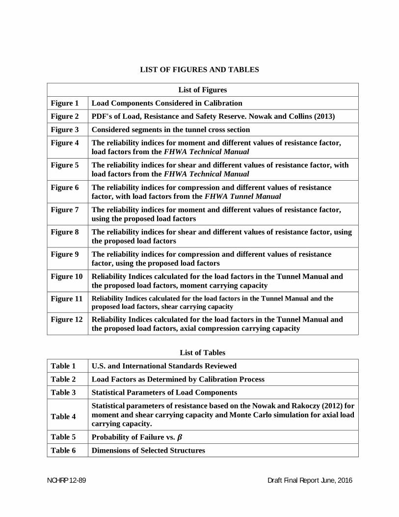
List of Figures
Figure 1 Load Components Considered in Calibration
Figure 2 PDF's of Load, Resistance and Safety Reserve. Nowak and Collins (2013)
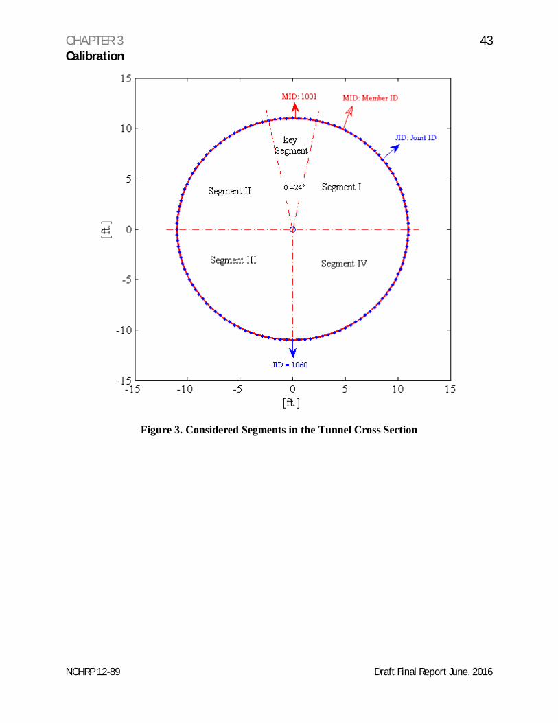
Figure 3 Considered segments in the tunnel cross section
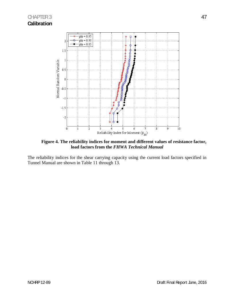
Figure 4 The reliability indices for moment and different values of resistance factor,load factors from the FHWA Technical Manual
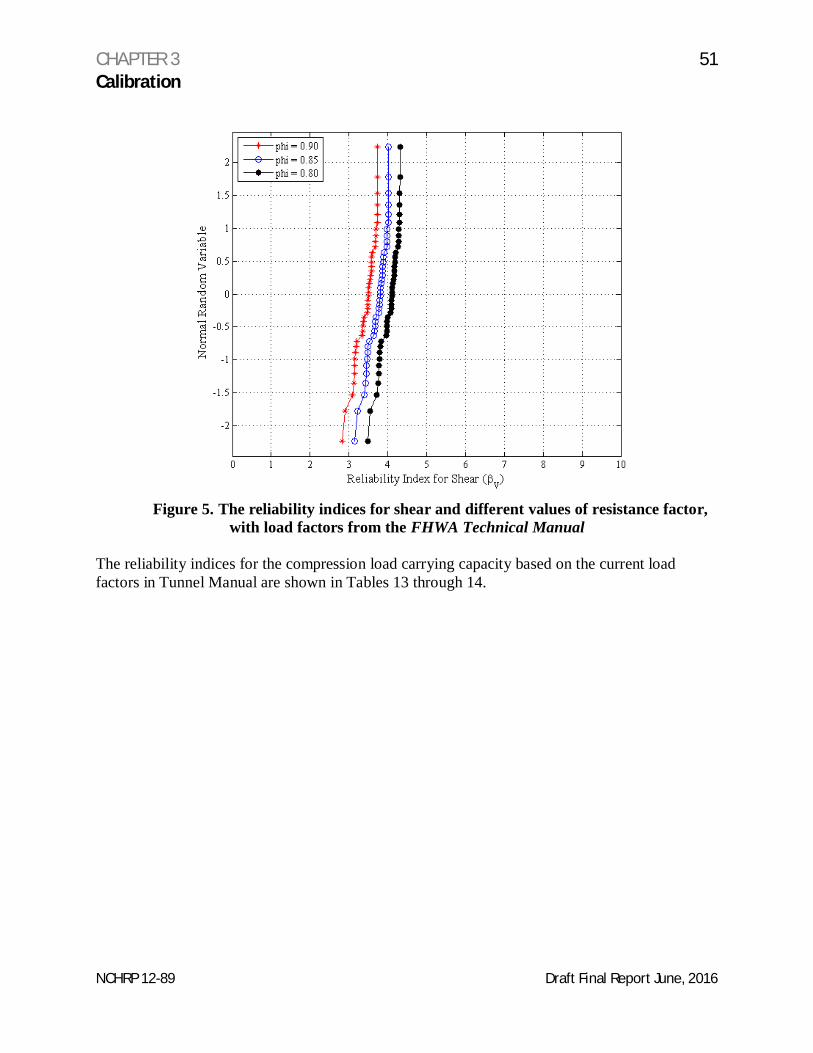
Figure 5 The reliability indices for shear and different values of resistance factor, withload factors from the FHWA Technical Manual
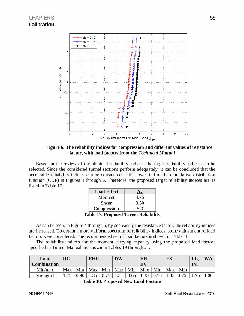
Figure 6 The reliability indices for compression and different values of resistancefactor, with load factors from the FHWA Tunnel Manual
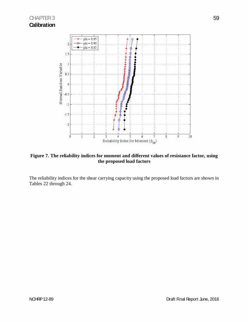
Figure 7 The reliability indices for moment and different values of resistance factor,using the proposed load factors
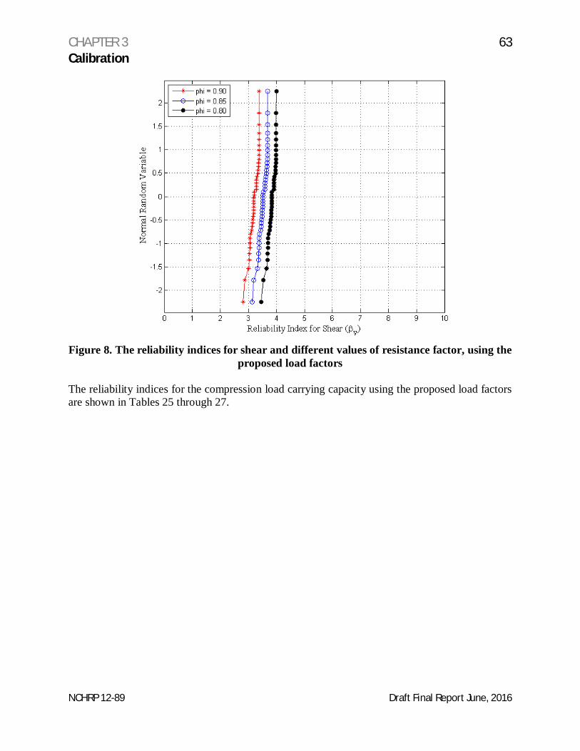
Figure 8 The reliability indices for shear and different values of resistance factor, usingthe proposed load factors
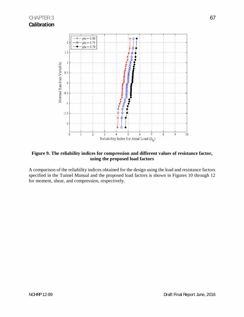
Figure 9 The reliability indices for compression and different values of resistancefactor, using the proposed load factors
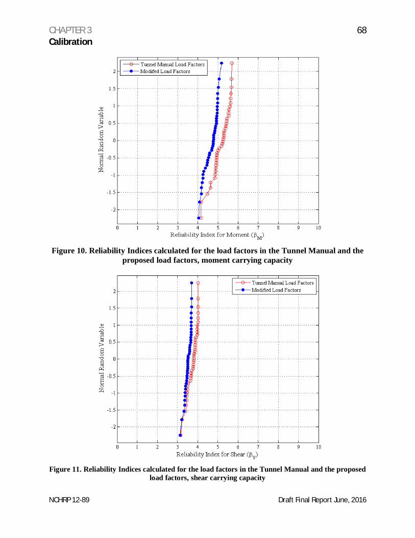
Figure 10 Reliability Indices calculated for the load factors in the Tunnel Manual andthe proposed load factors, moment carrying capacity
Figure 11 Reliability Indices calculated for the load factors in the Tunnel Manual and theproposed load factors, shear carrying capacity
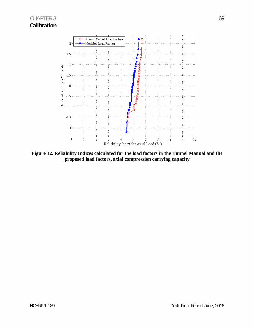
Figure 12 Reliability Indices calculated for the load factors in the Tunnel Manual andthe proposed load factors, axial compression carrying capacity
List of Tables
Table 1 U.S. and International Standards Reviewed
Table 2 Load Factors as Determined by Calibration Process
Table 3 Statistical Parameters of Load Components
Table 4Statistical parameters of resistance based on the Nowak and Rakoczy (2012) formoment and shear carrying capacity and Monte Carlo simulation for axial loadcarrying capacity.
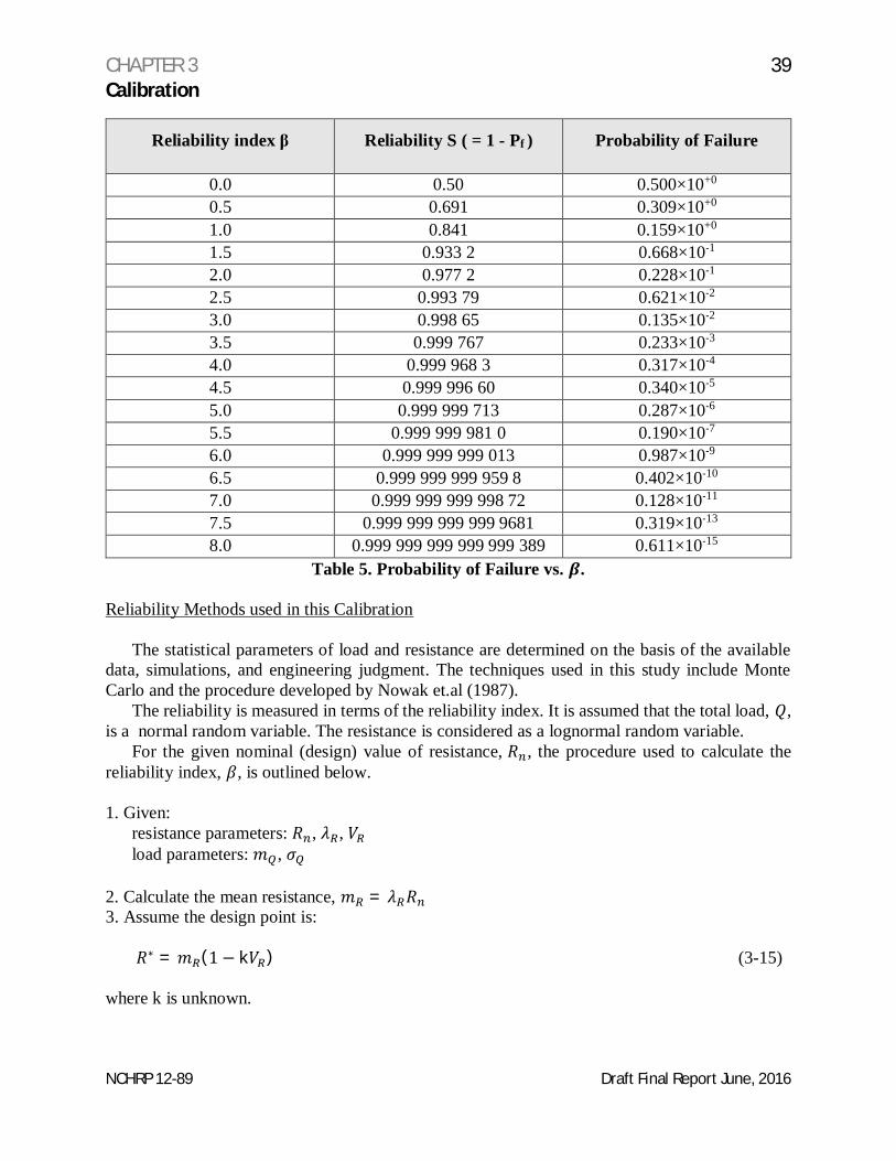
Table 5 Probability of Failure vs.
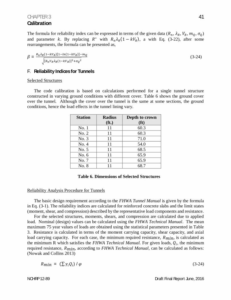
Table 6 Dimensions of Selected Structures
NCHRP 12-89 Draft Final Report June, 2016
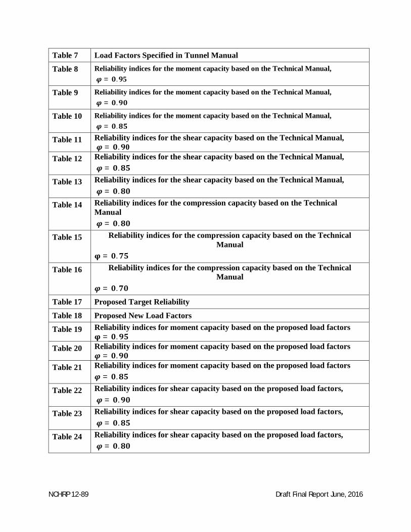
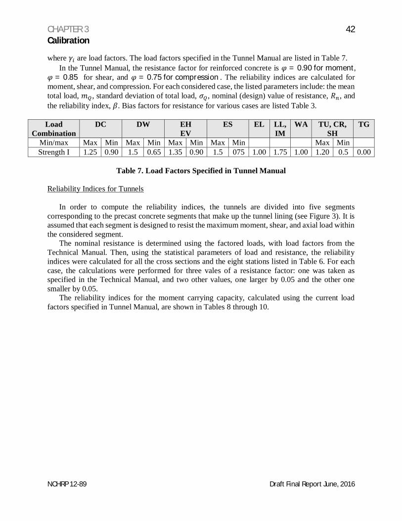
Table 7 Load Factors Specified in Tunnel Manual
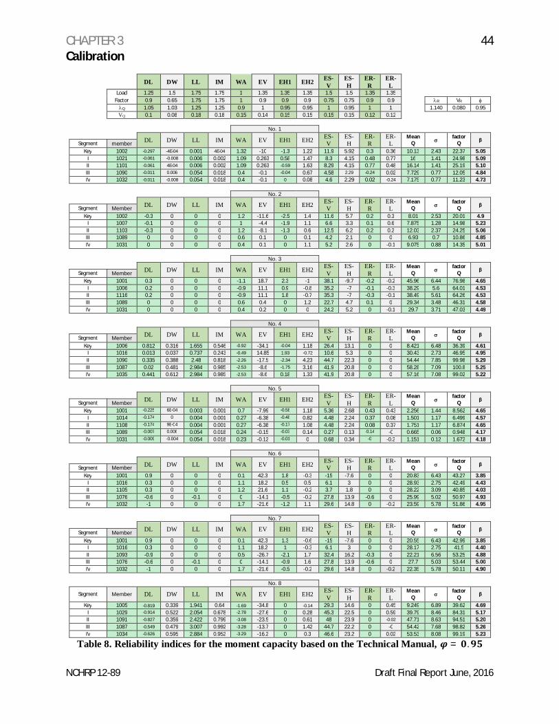
Table 8 Reliability indices for the moment capacity based on the Technical Manual,= . 5
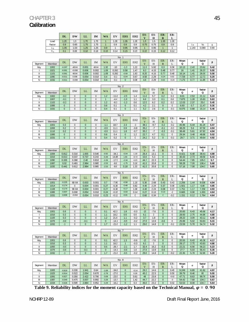
Table 9 Reliability indices for the moment capacity based on the Technical Manual,= .
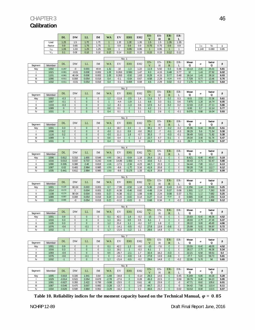
Table 10 Reliability indices for the moment capacity based on the Technical Manual,= .
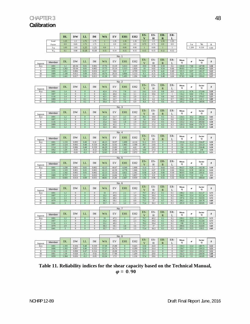
Table 11 Reliability indices for the shear capacity based on the Technical Manual,= . 0
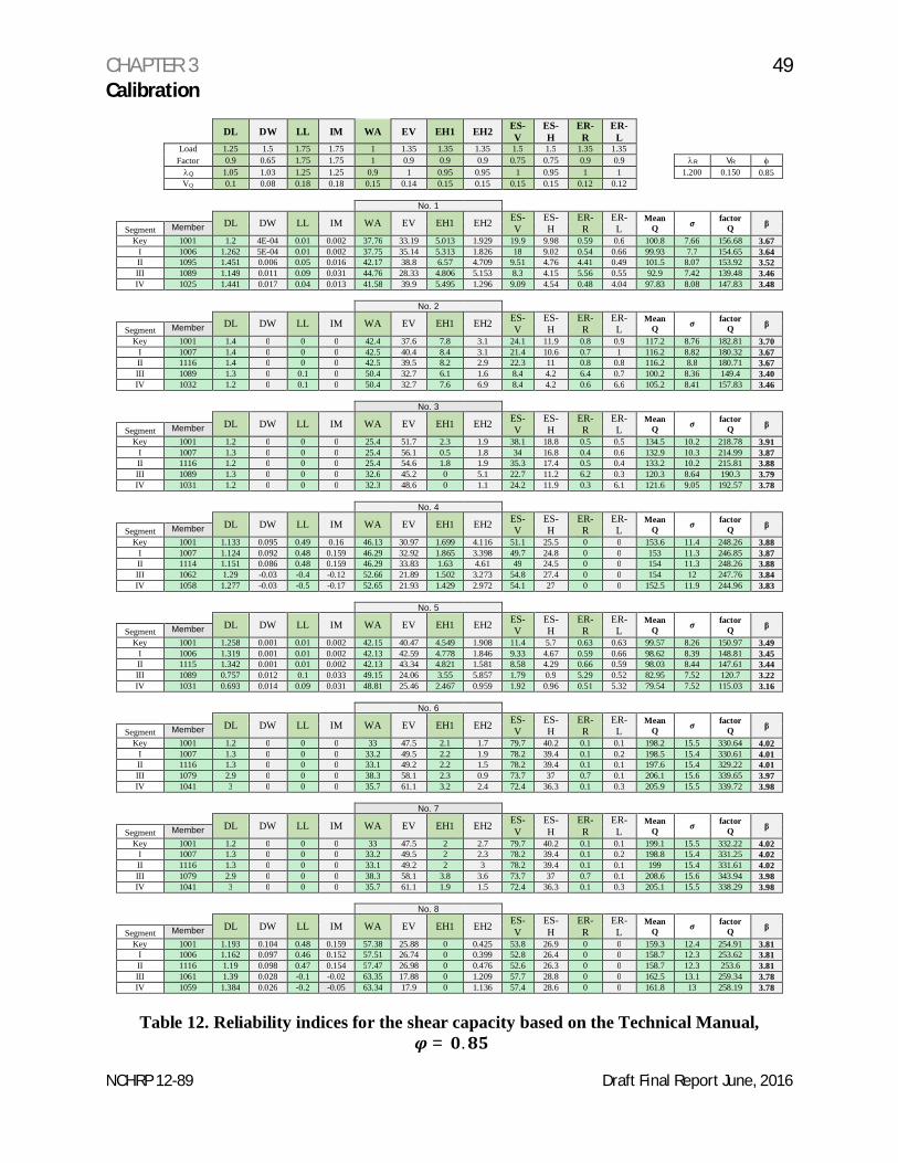
Table 12 Reliability indices for the shear capacity based on the Technical Manual,= .
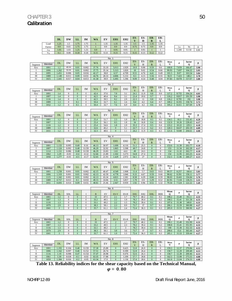
Table 13 Reliability indices for the shear capacity based on the Technical Manual,= .
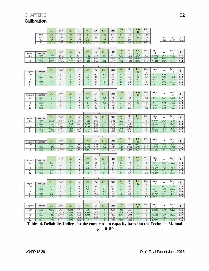
Table 14 Reliability indices for the compression capacity based on the TechnicalManual
= .
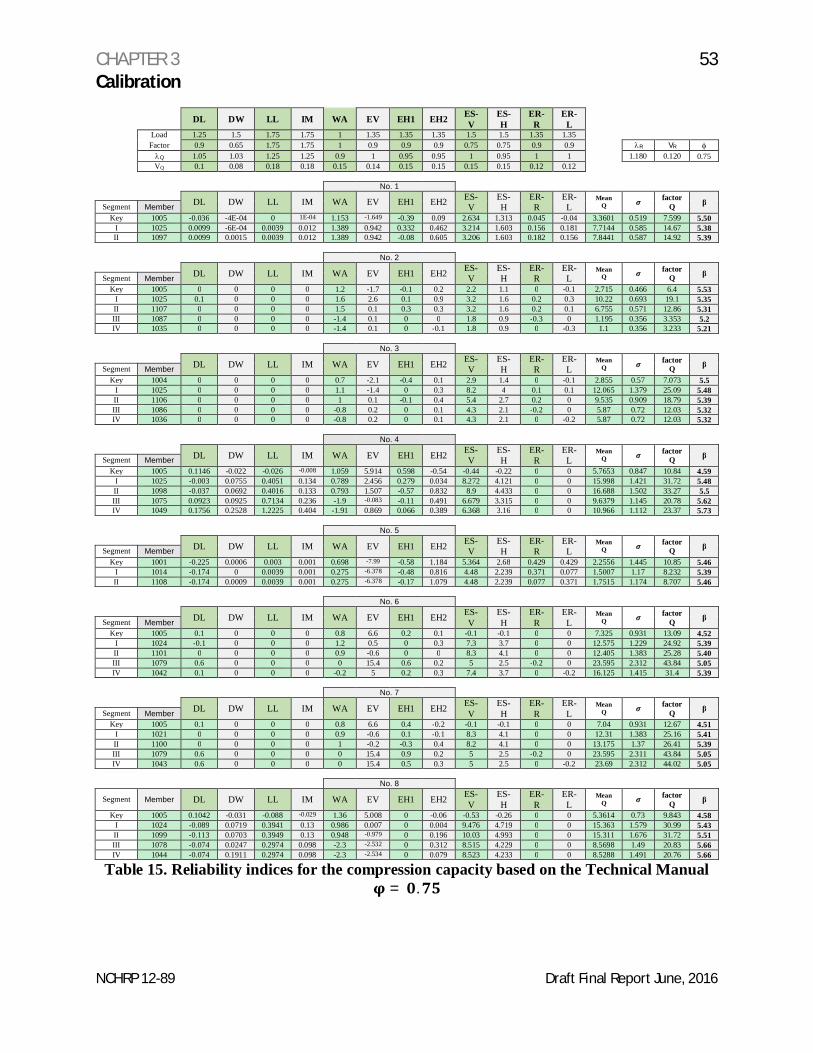
Table 15 Reliability indices for the compression capacity based on the TechnicalManual
= .
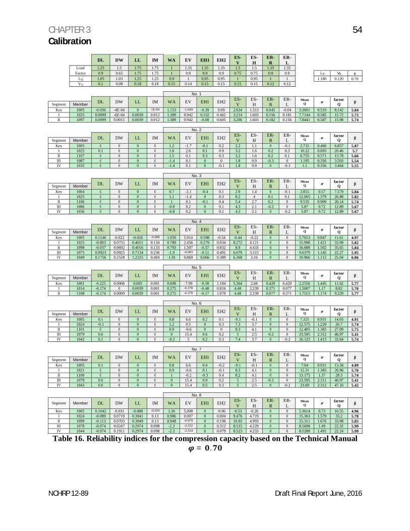
Table 16 Reliability indices for the compression capacity based on the TechnicalManual
= .
Table 17 Proposed Target Reliability
Table 18 Proposed New Load Factors
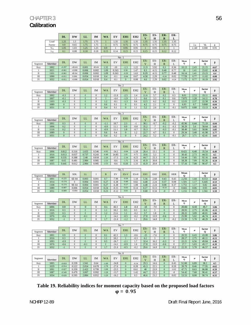
Table 19 Reliability indices for moment capacity based on the proposed load factors= .
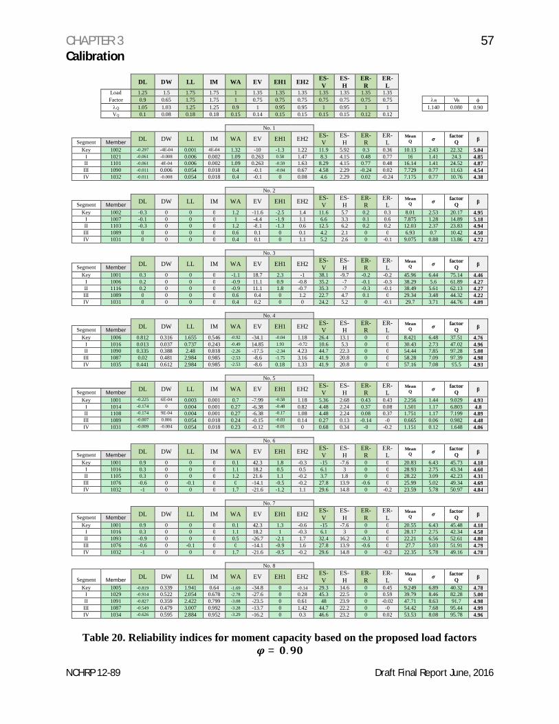
Table 20 Reliability indices for moment capacity based on the proposed load factors= .
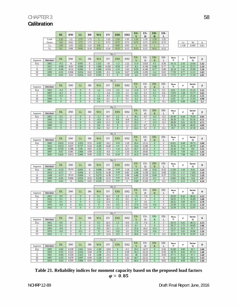
Table 21 Reliability indices for moment capacity based on the proposed load factors= .
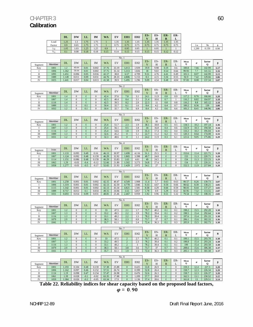
Table 22 Reliability indices for shear capacity based on the proposed load factors,= .
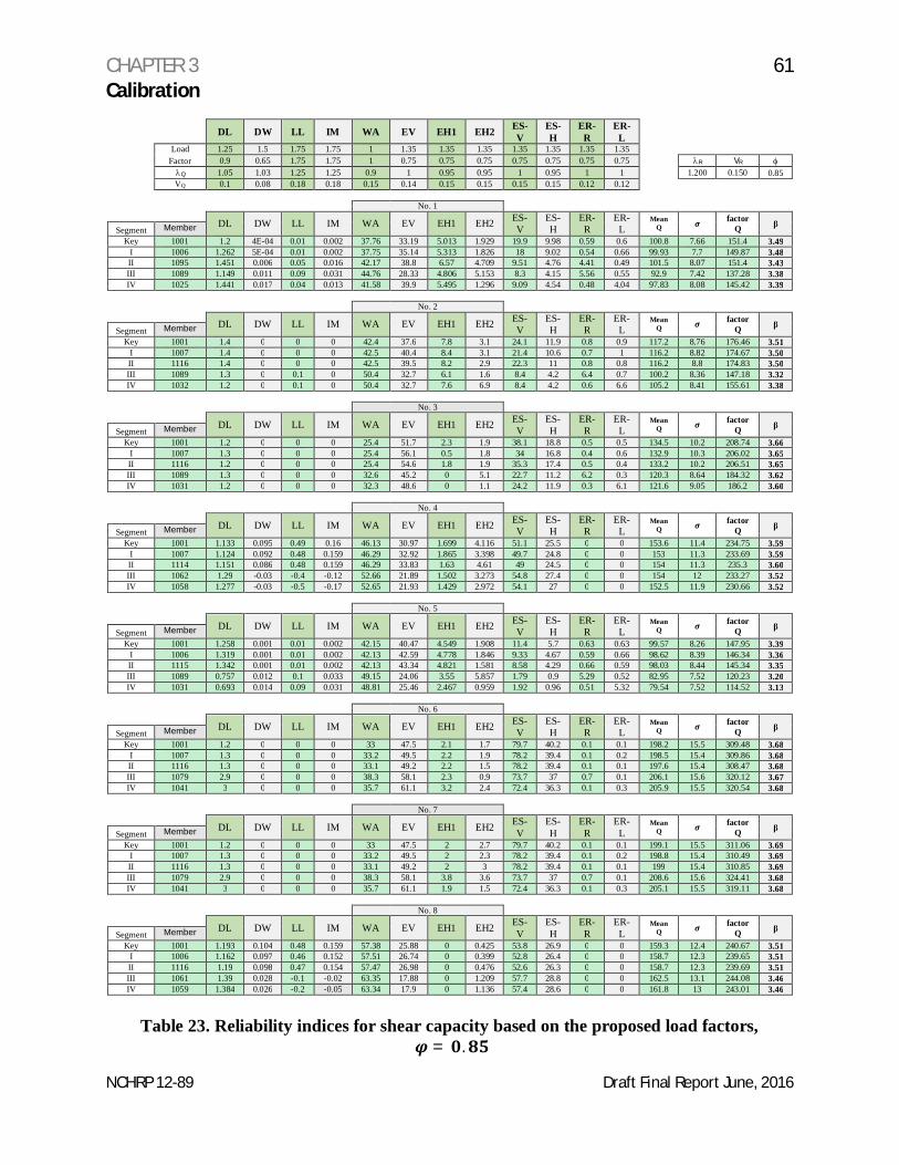
Table 23 Reliability indices for shear capacity based on the proposed load factors,= .
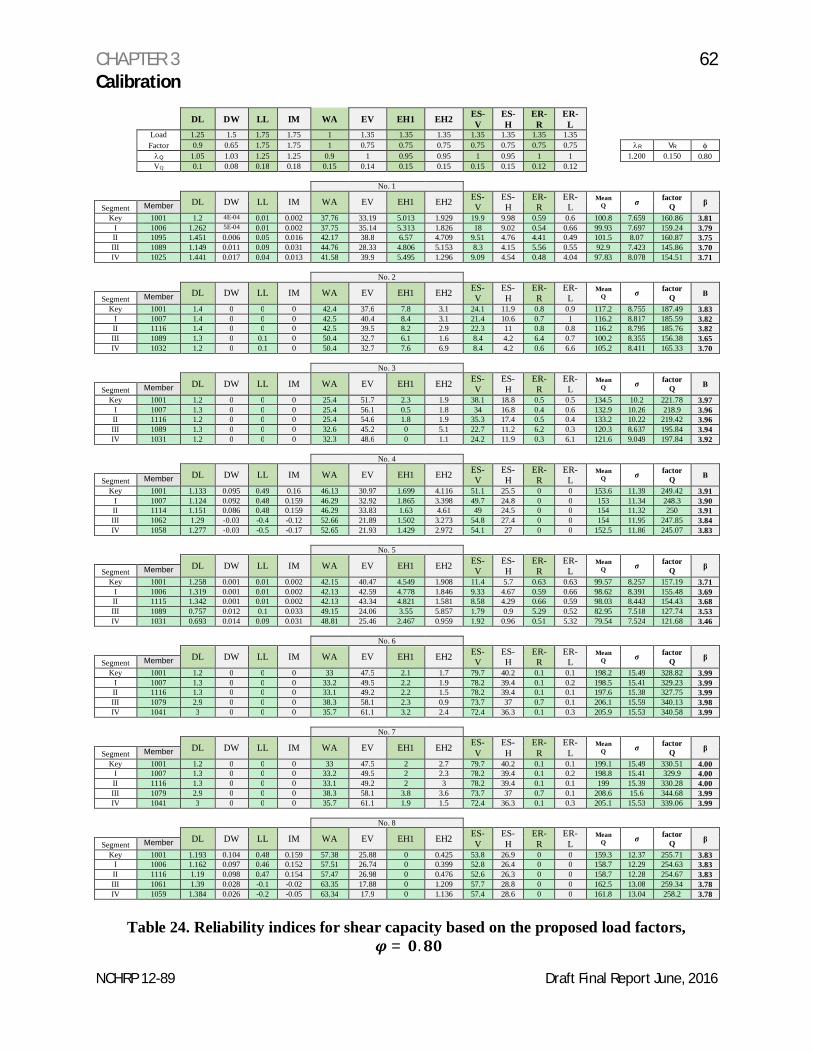
Table 24 Reliability indices for shear capacity based on the proposed load factors,= .
NCHRP 12-89 Draft Final Report June, 2016
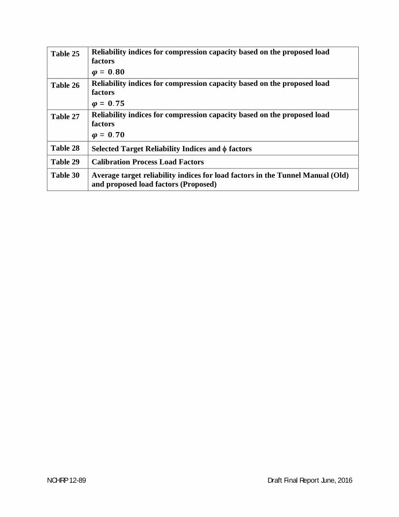
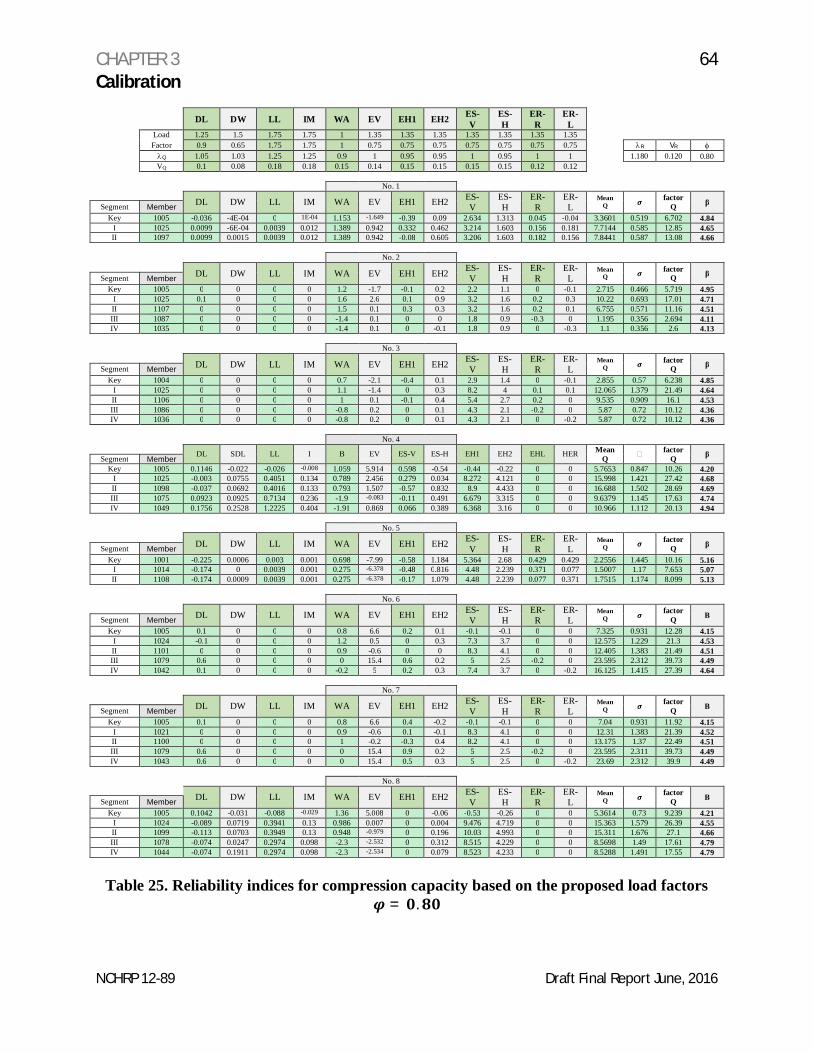
Table 25 Reliability indices for compression capacity based on the proposed loadfactors
= .
Table 26 Reliability indices for compression capacity based on the proposed loadfactors
= .
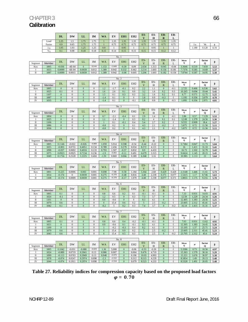
Table 27 Reliability indices for compression capacity based on the proposed loadfactors
= .
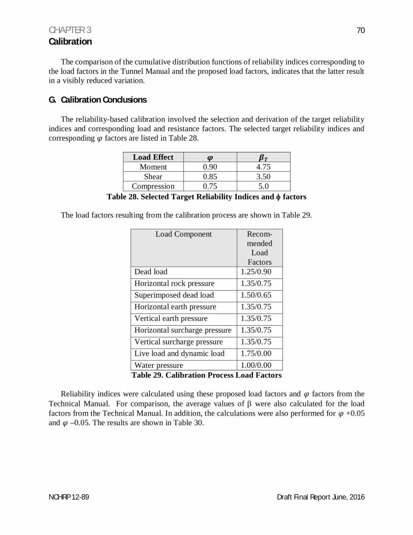
Table 28 Selected Target Reliability Indices and f factors
Table 29 Calibration Process Load Factors
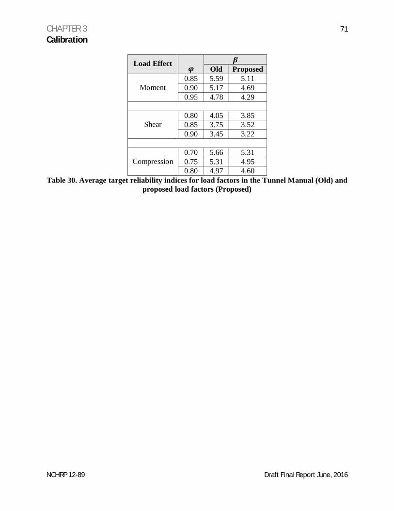
Table 30 Average target reliability indices for load factors in the Tunnel Manual (Old)and proposed load factors (Proposed)
NCHRP 12-89 Draft Final Report June, 2016
AUTHOR ACKNOWLEDGEMENTS
The research reported herein was performed under NCHRP Project 12-89 by WSP|ParsonsBrinckerhoff with subcontracting services being provided by Andrzej (Andy) Nowak of AuburnUniversity, Dennis Mertz of the University of Delaware, Youseff Hashash of the University ofIllinois at Urbana-Champaign and Remline Corporation.
The Principal Investigator on this project was John Wisniewski from WSP|ParsonsBrinckerhoff. The other authors of this report were Andrzej (Andy) Nowak and Jeremy Hung.
The following WSP|Parsons Brinckerhoff individuals made significant contributions to thespecifications developed as part of this research: Ismail Karatas, William Daley, RaymondCastelli, Christina Ingerslev, Donna Roberts, and Hamidreza Rezaei.
ABSTRACT
This report documents and presents the methodology used to develop recommended Load andResistance Factor (LRFD) based tunnel design specifications. A literature search was performedto review existing design codes and standards, project specific design criteria, reports, andtechnical publications. Limited calibration of the load factors was performed based on results fromthe analysis of a circular bored tunnel. A summary of the calibration procedure is presented in thereport. Future research to expand the specifications is provided. The design specifications arenot included in the report.
NCHRP 12-89 Draft Final Report June, 2016
CHAPTER 1 9Introduction and Research Approach
NCHRP 12-89 Draft Final Report June, 2016
A. Introduction
The objective of this research was to develop stand-alone recommended design andconstruction specifications for highway tunnel systems. In developing these specifications,consideration was given to safety, operations, maintenance, and inspection of tunnel systems. Theintent of this research was to develop recommended design and construction specifications withcommentary in the format of the American Association of State Highway and TransportationOfficials’ (AASHTO) Load and Resistance Factor (LRFD) Bridge Design Specifications. Theresulting specifications focus on design requirements for tunnel civil elements and tunnel systems.The specifications include civil design requirements for the following types of tunnels:
The two Appendices are included with the specifications. Specification Appendix A providesPlanning and Routes Considerations that address the environmental process and how it applies totunnel projects. Specification Appendix B provides a list of recommended tunnel constructionspecification sections for civil aspects of the tunnel. These are sections that are not included in theAASHTO LRFD Bridge Construction Specifications.
The research goal was to develop recommended design specifications for submittal toAASHTO for consideration to be adopted as guide specifications. This research was intended toproduce specifications that would provide the initial step towards codifying, in a single document,tunnel design in the United States (U.S.). The recommended specifications are intended for useby experienced tunnel designers. The recommended specifications are not intended to instructnovice engineers with regard to tunnel design.
Herein, the term LRFD Tunnel Specifications refers to the LRFD draft specifications developedas part of this project. Other AASHTO specification titles are referred to by the full title.
B. Organization
The project was divided into four phases that progressed sequentially. The phases of theproject are summarized below:
Phase I:§ A critical review of existing specifications, technical literature, and pertinent tunnel
publications and reports. The research included both foreign and domestic sources.§ Identification of knowledge gaps and an approach to fill these gaps.§ A detailed outline of the recommended specifications.§ A proposed sample specification section.
Phase II:§ A fully developed sample specification section.
CHAPTER 1 10Introduction and Research Approach
NCHRP 12-89 Draft Final Report June, 2016
Phase III:§ Fully developed specifications in AASHTO format.
Phase IV:§ Revised specifications incorporating the review panel’s comments.§ Recommended implementation plan.§ Final report.
The draft specifications have been written in the AASHTO LRFD format: specifically, a twocolumn format with specifications in the left-hand column and corresponding commentary in theright-hand column. The draft specifications have been reviewed by AASHTO TechnicalCommittee T-20 (Tunnels). The specifications are ready for implementation after review andpossible adoption by the Subcommittee for Bridges and Structures (SCOBS).
The recommended specifications as submitted for AASHTO ballot are included as Appendix1 to this report. The calibration work performed as part of this study is summarized in Chapter 3of this report and provides the start of a calibration process. The calibration was intended toprovide insight into the use of the load factors from the AASHTO LRFD Bridge DesignSpecifications. Additional work is recommended prior to adopting load factors different fromthose contained in the AASHTO LRFD Bridge Design Specifications.
This report summarizes the highlights of the work performed for the purpose of a generaloverview. The reader is encouraged to review the LRFD Tunnel Specifications for more detailedinformation.
C. Contents of the LRFD Tunnel Specifications
The LRFD Tunnel Specifications are organized in a similar manner to the AASHTO LRFDBridge Design Specifications. The first part of the LRFD Tunnel Specifications provides anintroduction and the requirements for general features, systems, loads and load factors, materials,and geotechnical considerations. The later sections deal with the design requirements for specifictunnel methodologies and seismic requirements. The LRFD Tunnel Specifications bring inrequirements from the AASHTO LRFD Bridge Design Specifications and other industryspecifications by reference.
All sections are written for maintainability and expansion as research and practice guidethe AASHTO tunnel community and AASHTO T-20.
The contents of the draft specifications are shown below:
Section 1: Introduction
Section 2: General Features and RequirementsSection 3: Loads and Load Combinations
Section 9: Initial Ground Support Elements and Ground ImprovementSection 10: Seismic Considerations
Appendix A: Planning and Route ConsiderationsAppendix B: Suggested Construction Specification Sections
CHAPTER 2 12Phased Research Results Summary
NCHRP 12-89 Draft Final Report June, 2016
A. Phase 1: Critical Review of Existing Information
Three general categories of information were investigated: design specifications andstandards, reports and research papers, and project specific design criteria. A summary of thefindings is presented in this section.
1. U.S. and International Specifications and Standards
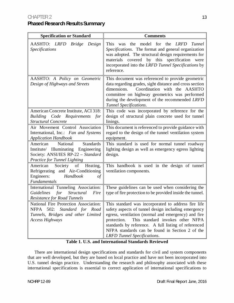
Domestic and selected international specifications and standards were reviewed forapplicability to the LRFD Tunnel Specifications. Table 1 summarizes the documents reviewed.The design of structural components is very well developed in U.S. practice, specifically withinthe AASHTO LRFD Bridge Design Specifications. Research on the design of structural elementswas therefore not conducted. However, two main components of the design process do notcurrently exist within the AASHTO LRFD Bridge Design Specifications: development of groundloads on the tunnel structure and the design approach to systems. Both components turned out tobe very well developed in U.S. practice, albeit not within the framework of load and resistancefactor design (LRFD). The following organizations have standards or codes that were incorporatedinto the LRFD Tunnel Specifications:
o American Concrete Institute (ACI)o Air Movement Control Association International, Inc. (AMCA)o American National Standards Institute/ Illuminating Engineering Society (ANSI/IES)o American Society of Heating, Refrigerating and Air-Conditioning Engineers (ASHREA)o International Tunneling Association (ITA)o National Fire Protection Association (NFPA)
Some international systems standards are in use in the United States and have been integratedinto the U.S. tunnel design practice. These standards are included in Table 1.
CHAPTER 2 13Phased Research Results Summary
NCHRP 12-89 Draft Final Report June, 2016
Specification or Standard Comments
AASHTO: LRFD Bridge DesignSpecifications
This was the model for the LRFD TunnelSpecifications. The format and general organizationwas adopted. The structural design requirements formaterials covered by this specification wereincorporated into the LRFD Tunnel Specifications byreference.
AASHTO: A Policy on GeometricDesign of Highways and Streets
This document was referenced to provide geometricdata regarding grades, sight distance and cross sectiondimensions. Coordination with the AASHTOcommittee on highway geometrics was performedduring the development of the recommended LRFDTunnel Specifications.
American Concrete Institute, ACI 318:Building Code Requirements forStructural Concrete
This code was incorporated by reference for thedesign of structural plain concrete used for tunnellinings.
Air Movement Control AssociationInternational, Inc.: Fan and SystemsApplication Handbook
This document is referenced to provide guidance withregard to the design of the tunnel ventilation systemequipment.
American National StandardsInstitute/ Illuminating EngineeringSociety: ANSI/IES RP-22 – StandardPractice for Tunnel Lighting
This standard is used for normal tunnel roadwaylighting design as well as emergency egress lightingdesign.
American Society of Heating,Refrigerating and Air-ConditioningEngineers: Handbook ofFundamentals
This handbook is used in the design of tunnelventilation components.
International Tunneling Association:Guidelines for Structural FireResistance for Road Tunnels
These guidelines can be used when considering thetype of fire protection to be provided inside the tunnel.
National Fire Protection Association:NFPA 502: Standard for RoadTunnels, Bridges and other LimitedAccess Highways
This standard was incorporated to address fire lifesafety aspects of tunnel design including emergencyegress, ventilation (normal and emergency) and fireprotection. This standard invokes other NFPAstandards by reference. A full listing of referencedNFPA standards can be found in Section 2 of theLRFD Tunnel Specifications.
Table 1. U.S. and International Standards Reviewed
There are international design specifications and standards for civil and system componentsthat are well developed, but they are based on local practice and have not been incorporated intoU.S. tunnel design practice. Understanding the research and philosophy associated with theseinternational specifications is essential to correct application of international specifications to
CHAPTER 2 14Phased Research Results Summary
NCHRP 12-89 Draft Final Report June, 2016
American practice. This is beyond the intent of the research. The development of thespecifications was focused on consolidating and codifying current U.S. tunnel design practice.
Although the U.S. practice is well developed and based on research and successful practice, itis compartmentalized.
Ground and groundwater loads are determined utilizing accepted practices developed fromresearch and data acquired through subsurface investigations and laboratory testing. Therequirements for minimum sampling, testing and reporting are not uniform across past practice.
Structural design utilizes allowable strength design and ultimate strength design depending onthe component being designed. No specific design specification is utilized for structural design.The structural design specification is usually designated in project specific design criteria.
Tunnel systems are generally designed to performance criteria. Numerous standards andspecifications covering the entire spectrum of tunnel systems are utilized in the design of tunnelsystems. The LRFD Tunnel Specifications incorporate existing specifications and standards usedin tunnel design by reference. This facilitates utilization of the most current specification orstandard without requiring an update to the LRFD Tunnel Specifications.2. Reports and Research Papers
Current research on tunnels performed under the National Cooperative Highway ResearchProgram (NCHRP) was reviewed and incorporated into the recommended LRFD Tunnel DesignSpecifications. The NCHRP research reports reviewed during the execution of this projectinclude:
· NCHRP 20-59(47) – Emergency Exit Signs and Marking Systems for Highway Tunnels,August 2015
· NCHRP 20-68A, Scan 09-05 – Best Practices for Roadway Tunnel Design, Construction,Maintenance and Operation, April, 2011
· NCHRP Report 611. Seismic Analysis and Design of Retaining Walls, Buried Structures,Slopes, and Embankments, 2008
· NCHRP Synthesis 415, Design Fires in Road Tunnels, 2011· NCHRP Report 525, Volume 12: Making Transportation Tunnels Safe and Secure, 2006
AASHTO’s Technical Manual for Design and Construction of Road Tunnels – Civil Elements(Technical Manual), provides much of the background and detailed information useful in theapplication of the LRFD Tunnel Specifications.
Tunnel design in the U.S. has relied upon publications such as the Technical Manual, researchpapers and reports generated for specific purposes. These papers and reports were reviewed foran understanding of the current state of the practice of tunnel design. This project was not designedto create new work in the area of tunnel design, but rather to incorporate existing work and practiceinto a single location and to adapt the work to the LRFD design philosophy. Much of the researchthat forms the basis for the state of the art of tunnel design in the U.S. is aged compared to researchperformed for the design of more common transportation infrastructure such and bridges, retainingwalls, sign structures and high mast light poles. The publication dates on some of the papers drewthe attention of reviewers who asked if there was more recent research.
The ability to inspect and maintain tunnels is of great interest to tunnel owners. In particular,the ability to inspect tunnels while maintaining traffic is desired. The LRFD Tunnel Specifications
CHAPTER 2 15Phased Research Results Summary
NCHRP 12-89 Draft Final Report June, 2016
have taken this concern into account. Tunnel elements should be easily accessed and not hiddenbehind architectural features. Access ways for maintenance and inspection should be taken intoaccount during the study phase of the project. Understanding that these features can add to theinitial cost of the project, there can also be savings over the life of the project, not only to owners,but also to users.
3. Tunnel Project Design Criteria
Tunnel projects in the U.S. and abroad enlist the use of design criteria to guide the designprocess. Design criteria are developed by owners. The design criteria dictate codes and standardsfor use in the design and minimum performance criteria for tunnel systems.
Design criteria from recent U.S. and international tunnel projects that were active during theconduct of this research were reviewed. The projects included both road and transit tunnels. Theroad tunnel projects provided information regarding systems used in road tunnels. There are civilelements common to all tunnels, regardless of the tunnel’s use. Items that fall into this categoryinclude initial and permanent ground support, tunnel linings, and ground and water loads. Thetransit project design criteria were reviewed with respect to these common civil elements. Thefollowing design criteria were reviewed as part of this research:
Road Tunnels:· Alaskan Way Viaduct, Seattle, Washington· Port of Miami Tunnel, Miami, Florida· Midtown Tunnel, Portsmouth and Norfolk, Virginia· Istanbul Straight Road Tube Crossing Project (Eurasia Tunnel), Istanbul, Turkey
Transit Tunnels:· Baltimore Red Line Design Criteria Manual, Baltimore, Maryland· Metro Rail Design Criteria, Los Angeles California· Trans-Hudson Expressway, New York and New Jersey
The design criteria reviewed had common elements and reflect the current state of practicewith regard to tunnel design in the United States. In general, the differences in the design criteriacan be attributed to owner preference regarding specific components or systems. The commonelements are summarized below:
· Common U.S. design codes and specifications required for civil and structural elements:o AASHTOo ACIo International Building Code (IBC)o American Institute of Steel Construction (AISC)o American Association of Civil Engineers (ASCE)
CHAPTER 2 16Phased Research Results Summary
NCHRP 12-89 Draft Final Report June, 2016
· Common design standards required for systems and system components:o NFPAo ASHRAEo International Electric Code (IEC).
B. Phase 1: Identification of Knowledge Gaps
The Research Team identified knowledge gaps and research needs such as new and modifiedlimit states, loads, and load combinations and resistance factors. These and other research activitiesare described below.
1. New and/or Modified LRFD Limit States
A limit state is defined as a condition at which some component of the structure (orgeotechnical feature) no longer fulfills its design function. The AASHTO LRFD Bridge DesignSpecifications identify twelve potential limit states that may require evaluation for design of abridge. These include five limit states pertaining to strength, four pertaining to serviceability, twopertaining to extreme events, and two pertaining to fatigue. A unique combination of loads isspecified for each of the twelve limit states. These limits states are not directly applicable to roadtunnel design due primarily to the differences in behavior and loading between bridges and roadtunnels. This NCHRP study identified potential limit states (or failure modes) for each type of roadtunnel (i.e. cut-and-cover tunnels, mined and bored tunnels, and immersed tunnels). CurrentAASHTO LRFD Bridge Design Specifications limit states were modified for use with each tunneltype and new limit states were proposed. The final research result is in the form of a new loadcombination table with applicable new and/or modified limit states and loads relevant to each typeof road tunnel.
Similar to the construction of bridges, tunnel construction has temporary conditions that occurprior to the completion of the tunnel construction. The temporary conditions involve thedisturbance of the existing state of stress in the ground surrounding the tunnel. This disturbancewill result in immediate redistribution of stresses followed by a slower process of stressredistribution during which the ground reaches equilibrium. The immediate redistribution ofstresses creates a short term condition that must be resisted by temporary or permanent structuralelements that work together with the ground. The temporary structural elements required toprovide the initial stability of the opening (temporarily) are usually sacrificial elements that arenot accounted for in the design of the permanent structure.
The LRFD Tunnel Specifications provide guidance for LRFD design of final (i.e. permanent)road tunnel structures. However, there are known temporary conditions that may govern thedesign of a final tunnel structure. For example, the final bored tunnel structural elements such asprecast concrete tunnel linings are subjected to both the temporary and permanent loadingconditions and must be checked for both conditions. The load of a tunnel boring machine jackingagainst a precast segmental tunnel lining during construction may govern the design. Anotherexample is the loading conditions experienced by immersed tunnel elements during fabrication,transportation and placement.
These critical load conditions during construction stages require a limit state (or loadcombinations) that has been introduced in the LRFD Tunnel Specifications. These construction
CHAPTER 2 17Phased Research Results Summary
NCHRP 12-89 Draft Final Report June, 2016
load conditions can be heavily influenced by the contractor’s means and methods, therefore, adistinction has been made between the roles and responsibilities of the owner’s designer and thecontractor.
The literature search performed for this report uncovered little U.S. information with regard toLRFD design of tunnels. Many disciplines have not developed LRFD processes. Althoughstructural LRFD is well developed for bridges, and some of that information is transferable totunnel design, many of the structural and geotechnical aspects of tunnel design have no guidanceat all. This lack of information required the original generation of information required to developthe specifications.
2. Loads, Load Combinations, and Load Factors
• Loads:
Potential loads (and load components) were reviewed and compared to the loads as specifiedin the current AASHTO Bridge Design Specifications. New or modified loads and load definitionswere generated for each type of tunnel. Loads that were not directly transferable from the AASHTOBridge Design Specifications were modified or originated for the LRFD Tunnel DesignSpecifications. Loads with a larger uncertainty, such as ground and groundwater loads, wereaddressed and treated accordingly through the load factors and load combinations.
Examples of loads unique to tunnels include: air pressure generated by tunnel ventilationsystems, loads on top of immersed tunnels as a result of a sunken ship or a dragging anchor andthe thrust imposed on tunnel linings by a tunnel boring machine.
• Short Term Ground and Water Loads:
Short term ground and water loads encountered during construction are included in thespecifications through the construction stage limit states and load combinations. Short term loadstypically are thought of as having lower load factors due to a shorter exposure and the monitoringtypically in place during construction. However, the uncertainty associated with predicting shortterm loads, combined with the lack of technology to verify the loads, require higher load factorsfor temporary loads than would be typical for better defined loads associated with bridges in spiteof the shorter exposure.
• Construction (i.e. temporary or short-term) Loads:
As discussed above, some load conditions during the construction stages can be significant forthe design of the final tunnel structural elements and, at times, can control the design of manystructural components of a tunnel. For example, the loads imposed on segmental concrete liningsby the construction process are frequently more demanding than the ground and water loads thelining supports during service. Appropriate load combinations and resistance factors for criticalconstruction loads were identified and presented in the LRFD Tunnel Specifications.
CHAPTER 2 18Phased Research Results Summary
NCHRP 12-89 Draft Final Report June, 2016
• Load Factor Calibration:
Because most road tunnels are critical (from life-safety, access and redundancy aspects), andowners require longer service life (over 100 years), it is likely that the reliability index for loadfactor calibration should be higher than the value used for standard bridges and highway structuresin the current AASHTO LRFD Bridge Design Specifications. A limited load factor calibrationexercise was therefore performed as part of this study. The details and findings of the study areincluded in Chapter 3 of this report.
• Tunnel Design Life
The design life was examined and was the topic of much discussion during the researchprocess. With proper maintenance, tunnels are expected to have a service life in excess of 100-years. Recent projects (the Port of Miami Tunnel and the Midtown Tunnel) have set the servicelife of the tunnel at 125 years. Many existing tunnels in the United States have reached or exceededthe 100-year mark. There are no plans or need to replace these tunnels in the near future. Giventhe substantial investment required to construct a tunnel and the technical and economic challengesassociated with widening or replacing existing road tunnels, careful thought must be given to amore optimal design life expectancy and the design code calibrated accordingly. A design life of150 years is recommended in the LRFD Tunnel Specifications.
3. Resistance Factors
• Materials:
Materials used in tunnel construction such as ground reinforcement elements, shotcrete, fiberreinforced concrete and lattice girders do not have established resistance factors. Designersfrequently rely on published manufacturer’s literature to obtain ultimate and permissiblecapacities. There is little uniformity in the testing employed by manufacturers makingestablishment of resistance factors for these materials difficult. Some products are notmanufactured in the United States, creating even more difficulty in standardizing the performanceof these items.
Temporary (i.e. initial) support elements and geotechnical features are required to maintain asafe and acceptable opening during mined and/or bored tunnel construction. These elements andfeatures, such as rock bolts and shotcrete, are intended to interact with surrounding geo-materialsto establish a stable opening during construction and often do not exceed their full geotechnicalcapacity as long as the entire system stability is satisfied during the service limit state. The variablenature of geomaterials, even within the typical spacing of these elements, makes reliability difficultto predict.
Materials were separated into two categories; 1.) structural elements and materials that form afinal tunnel structure, and 2.) other materials and elements required to maintain temporary (initial)stability of opening such as rock bolts that rely heavily on the ability of the surrounding ground totransfer load. Temporary elements have traditionally been designed to a factor of safety.Resistance factors for temporary elements were assigned in the LRFD Tunnel Specifications toresult in the traditional safety factors currently in use.
CHAPTER 2 19Phased Research Results Summary
NCHRP 12-89 Draft Final Report June, 2016
• Ground Improvement:
Ground improvement techniques are another source of uncertainty in the design process.These processes are usually performance based and require frequent adjustment in the field toobtain the desired results. The LRFD Tunnel Specifications have been written so that performancecriteria are developed by the designer. The performance criteria are conveyed to the contractorthrough the construction specifications. This is the methodology currently used to deal withground improvement.
• Geo-Materials:
Geo-materials are the ground surrounding the tunnel. The basic premise of tunnel design isthat the surrounding ground interacts with the structural elements of the tunnel to create a stableopening. The wide range of geo-materials makes determination of resistance factors difficult withregard to developing factors that could be universally applicable. The current practice of defininggeo-material properties has been incorporated into the LRFD Tunnel Specifications. The designapproach incorporated in the LRFD Tunnel Specifications is to use the geo-material properties astraditionally determined and to not assign a resistance factor to the geo-materials. The uncertaintyand variability of the geo-material properties is accounted for in the earth-load load factors and thestructural materials’ resistance factors.
4. Criteria for Fire and Life Safety Considerations
• Fire Safety:
NFPA Standard 502 is the internationally recognized standard for road tunnel and highway fireprotection and establishes the minimum fire and life safety requirements for road tunnels, bridgesand other roadways where access by emergency responders is physically limited. The NFPA 502Technical Committee has released the 2014 edition of the Standard. This recent versionincorporates several new requirements addressing the following topics:
· Fire Curve/Fire Growth Rate/Heat Release Rate· Electrical Systems· Emergency Egress· Fixed Fire Suppression/Standpipe Systems· Bridges and Limited Access Roadways· Emergency Response· Ventilation· Tunnel Length· Tunnel Drainage· Minimum Operating Elements· Alternative Fuels· Risk Assessment/Engineering Analysis
CHAPTER 2 20Phased Research Results Summary
NCHRP 12-89 Draft Final Report June, 2016
The 2014 edition of the Standard also includes new requirements and information which drawlargely from what has been learned from several recent road tunnel safety research programsincluding:
· The National Fire Protection Research Foundation (NFPRF) -Road Tunnel Fire DetectionResearch Project
· Sandia National Laboratories Research on Hydrogen Fueled Vehicles in Road Tunnels· The American Association of State Highway and Transportation Officials (AASHTO)
Research on Safety and Security in Roadway Tunnels.
As NFPA looks forward to the future, the goal of the 502 Technical Committee is to continuemonitoring the several significant national and international test programs that are on-going andto use the data from that research to help generate new technical requirements in NFPA 502.
The International Tunneling Association’s Guidelines for Fire Resistance for Road Tunnelswas also reviewed as part of this research.
The design for life safety considerations is generally associated with emergency access andegress, ventilation (as it deals with smoke and heat), early warning systems for gases, firesuppression systems and initiation of fire suppression systems, response planning, visualmonitoring, and traffic control during incidents. These items, although vital to the safe operationof a tunnel do not all fall into the purview of an LRFD based design specification. Relevantelements of these items are addressed in the specification in terms of how to incorporate them intothe tunnel structure and operating systems and make reference to industry standards that governtheir design.
The specification provisions provided are considered guidance for consideration by owners.
5. Tunneling and Construction Technologies
• Large Diameter Tunnel Boring Machines (TBMs):
The study considered the latest tunneling and construction technologies used in road tunneldesign and construction. For example, modern pressurized-face closed shield TBMs arepredominantly utilized in large diameter soft-ground tunneling. TBM manufacturers worldwidehave been developing larger and more technologically advanced machines that create newopportunities and reduce costs. Advancements that require study are not just on the TBM alone.The Alaskan Way Viaduct tunnel in Seattle involves a TBM with a diameter of over 54 feet, oneof the largest in the world. The use of large diameter bores affects the size, thickness andsegmentation of precast segmental one-pass tunnel linings as well as the design and constructionof cast-in-place linings used in two-pass lining systems. Additional research is required to quantifythe effects on the ground support systems associated with increasing diameters. These effectsshould be included in the development of the resistance factors for lining systems. This has beenidentified as topic for future research.
CHAPTER 2 21Phased Research Results Summary
NCHRP 12-89 Draft Final Report June, 2016
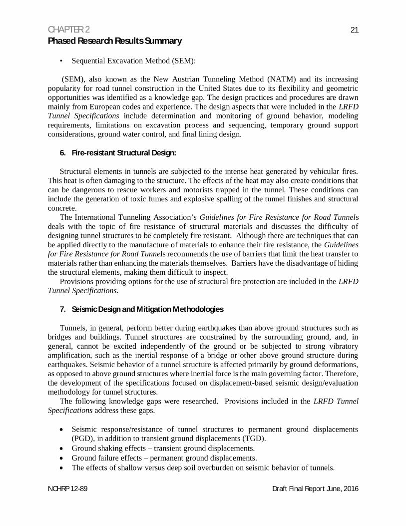
• Sequential Excavation Method (SEM):
(SEM), also known as the New Austrian Tunneling Method (NATM) and its increasingpopularity for road tunnel construction in the United States due to its flexibility and geometricopportunities was identified as a knowledge gap. The design practices and procedures are drawnmainly from European codes and experience. The design aspects that were included in the LRFDTunnel Specifications include determination and monitoring of ground behavior, modelingrequirements, limitations on excavation process and sequencing, temporary ground supportconsiderations, ground water control, and final lining design.
6. Fire-resistant Structural Design:
Structural elements in tunnels are subjected to the intense heat generated by vehicular fires.This heat is often damaging to the structure. The effects of the heat may also create conditions thatcan be dangerous to rescue workers and motorists trapped in the tunnel. These conditions caninclude the generation of toxic fumes and explosive spalling of the tunnel finishes and structuralconcrete.
The International Tunneling Association’s Guidelines for Fire Resistance for Road Tunnelsdeals with the topic of fire resistance of structural materials and discusses the difficulty ofdesigning tunnel structures to be completely fire resistant. Although there are techniques that canbe applied directly to the manufacture of materials to enhance their fire resistance, the Guidelinesfor Fire Resistance for Road Tunnels recommends the use of barriers that limit the heat transfer tomaterials rather than enhancing the materials themselves. Barriers have the disadvantage of hidingthe structural elements, making them difficult to inspect.
Provisions providing options for the use of structural fire protection are included in the LRFDTunnel Specifications.
7. Seismic Design and Mitigation Methodologies
Tunnels, in general, perform better during earthquakes than above ground structures such asbridges and buildings. Tunnel structures are constrained by the surrounding ground, and, ingeneral, cannot be excited independently of the ground or be subjected to strong vibratoryamplification, such as the inertial response of a bridge or other above ground structure duringearthquakes. Seismic behavior of a tunnel structure is affected primarily by ground deformations,as opposed to above ground structures where inertial force is the main governing factor. Therefore,the development of the specifications focused on displacement-based seismic design/evaluationmethodology for tunnel structures.
The following knowledge gaps were researched. Provisions included in the LRFD TunnelSpecifications address these gaps.
· Seismic response/resistance of tunnel structures to permanent ground displacements(PGD), in addition to transient ground displacements (TGD).
· Ground shaking effects – transient ground displacements.· Ground failure effects – permanent ground displacements.· The effects of shallow versus deep soil overburden on seismic behavior of tunnels.
CHAPTER 2 22Phased Research Results Summary
NCHRP 12-89 Draft Final Report June, 2016
· Liquefaction and resulting ground displacement effects.· Seismic slope instability and landslide displacement effects.· Active fault crossing displacement effects.· The appropriate design earthquake hazard level(s) were investigated. In general, road
tunnels have a longer service life than bridges (over 100 years), and are critical from life-safety, access and redundancy aspects. The design hazard level (or two or multiple levels)used currently in AASHTO LRFD Specifications (i.e. 1000-year) was reviewed andevaluated. The provisions included in the LRFD Tunnel Specifications are the consensusof numerous entities responsible for the design, operation and maintenance of road tunnels.
· The “no-analysis required” criterion was evaluated. Given that tunnels have performedmuch better than other highway structural components (e.g., bridges and foundations), the“no-analysis required” criterion for the bridge structures in the current seismic provisionsof the AASHTO LRFD Bridge Design Specifications was determined to be not applicableto tunnel structures. A separate screening criterion was developed taking into account boththe ground shaking intensity and the project geological site conditions.
· Since road tunnels are long, linear features commonly needed for crossing bodies of water,traversing adverse geological features, or connected to shafts/vent-buildings, their seismicbehavior in the longitudinal direction is complex and must consider the following factors(1) spatially varying ground motions effect (in terms of differential displacements), (2)basin effect, and (3) potential needs for seismic/flexible joints at soil/rock interface andtunnel/shaft or tunnel/vent-building interface. These factors have been included in theLRFD Tunnel Specifications.
8. Tunnel Systems and Security Requirements
Systems:
Tunnel operation and safety relies on a variety of monitoring and active systems. Thesesystems include closed circuit television (CCTV) monitoring, security (door locks, intrusionalarms, cameras, etc.) signing and signaling, lighting, communications (for operations,maintenance and emergency responders), ventilation (normal and emergency modes) tunnelfinishes, drainage, pumps, pavement, emergency response equipment (fire suppression andprotection), power supply (normal and emergency) and distribution.
Since tunnels provide short and direct traversing of natural features, owners of public andprivate utilities often seek permission to install their facilities inside tunnels. Code provisions forfire-life safety of third party utilities should comply with the fire and life safety provisions adoptedby the tunnel owner.
Security issues associated with tunnels include protection against natural events (storms,earthquakes, etc.), limiting access to non-roadway portions of the tunnel and protecting againstmalevolent acts. Systems must incorporate elements to mitigate these risks.
The design of systems is not easily adapted to the LRFD philosophy, and the disciplines thatdesign these systems typically do not design within the LRFD environment. System design isgenerally performance based. Systems are included in Section 2 of the LRFD TunnelSpecifications.
CHAPTER 2 23Phased Research Results Summary
NCHRP 12-89 Draft Final Report June, 2016
Security:
Security related matters are assessed and included as appropriate, including access to thetunnel, threat analysis, and reacting to natural disasters. These are facility specific sensitivematters that should be addressed by each individual owner based on the specifics of individualtunnels. Typical security systems are included in the LRFD Tunnel Specifications. Individualtunnel owners should undertake threat, vulnerability, and risk assessments as part of the planningand design process to determine the appropriate security systems to be included in a tunnel project.
An explosion inside a tunnel produces results different from an explosion in open air. Thecause of the explosion can dictate its magnitude. The analysis of effects of explosions on tunnelsis a complicated and security sensitive issue. The need and scope for this type of analysis fortunnels is touched on in the LRFD Tunnel Specifications, but specific requirements are notpresented. Specific requirements should be developed on tunnel specific basis developed inconjunction with a threat and vulnerability analysis. The analysis should include considerationsfor structural hardening, operational protocols, maintenance routines and communication with lawenforcement agencies.
C. Phase 1: Detailed Specification Outline and Proposed Specification Section
A detailed outline of the LRFD Tunnel Specifications was developed to guide the developmentof the complete documents. The early version of the outline evolved during the development ofthe LRFD Tunnel Specifications into the table of contents shown in Appendix A.
The sample specification that was developed dealt with concrete, specifically reinforcedconcrete, structural plain concrete and steel fiber reinforced concrete. This material specificationwas selected because it represented the three different ways that design specifications would beincluded in the LRFD Tunnel Specifications. Reinforced concrete design is very well developedin the LRFD Bridge Design Specifications, therefore, the design of reinforced concrete is governedby the LRFD Bridge Design Specifications which are invoked by reference in the LRFD TunnelSpecifications. ACI 318, Building Code Requirements for Structural Concrete includes provisionsfor the design of structural plain concrete and is incorporated by reference into the LRFD TunnelSpecifications. At the time of this research, there was no design specification for steel fiberreinforced concrete. New design requirements were developed for the LRFD TunnelSpecifications from research performed in the design industry.
D. Phase 2: Fully Developed Specification Section
This phase of the work involved the development of the specification section described inParagraph C immediately above. Originally, the LRFD Tunnel Specifications were organized toinclude separate sections for each structural material, similar to the way the AASHTO LRFD BridgeDesign Specifications are organized. It quickly became apparent that the best approach tostructural materials was to include them all into one section. This was due primarily to the factthat design specifications for structural materials were generally very well developed and could beincluded in the LRFD Tunnel Specifications by reference. This sample specification section wastherefore expanded to include all structural materials.
CHAPTER 2 24Phased Research Results Summary
NCHRP 12-89 Draft Final Report June, 2016
E. Phases 3 & 4: Fully Developed Specifications and Implementation Plan
Through a series of iterations and reviews by the NCHRP review panel, a final draft set ofrecommend specifications was developed. The specifications were developed as draft guidespecifications with the intention of submission to AASHTO for consideration for adoption.
Once the research team and review panel had come to consensus that the specifications wereat a sufficient level of development to present to AASHTO for consideration for adoption, anindustry review meeting was convened. The industry review meeting was attended by theresearch team, the NCHRP 12-89 review panel, AASHTO T-20 committee members, tunnelowners and tunnel consultants. Attendees were provided copies of the LRFD TunnelSpecifications for review prior to the meeting. Reviewers’ comments were sent to the researchteam prior to the meeting. The research team prepared responses to the comments and developedquestions and discussion points for discussion during the meeting.
The meeting was held over a two day period in October, 2015 where all comments and pointsof discussion were resolved, with the ultimate intent of recommending the draft LRFD TunnelSpecifications for a 2016 AASHTO ballot item. Review comments were incorporated into thespecifications and the draft specifications were submitted to AASHTO in December, 2015 forinclusion as a 2016 ballot item. As of the writing of this report, the AASHTO review of the ballotitem is underway.
CHAPTER 3 25Calibration
NCHRP 12-89 Draft Final Report June, 2016
The calibration work was performed by the research team at Auburn University under thedirection of Professor Andrzej S. Nowak. The calibration work was performed as an initial stepusing design data that were available from an on-going design project. The on-going design projectinvolved a circular bored tunnel utilizing one pass, precast concrete, bolted, gasketed segments forground support. This project was selected due to the availability of the analysis results for variableground and groundwater conditions. The calibration effort is considered a first step. Fullcalibration for the range of ground and groundwater conditions combined with the variety of tunnelsizes and configurations is expected to be an on-going process that evolves along with the futuredevelopment of the LRFD Tunnel Specifications. The calibration report procedures and results arepresented in this section.
A. Introduction
The objective of the calibration study was to provide background information for thecalibration of the design specifications for tunnels. The load and resistance factors were selectedusing available statistical models and probability-based procedures.
This section describes the calibration procedure, i.e. selection of load and resistance factors.The major steps include selection of representative structures, calculation of reliability for theselected structures, selection of the target reliability index and calculation of trial load factors andresistance factors. The report also reviews load and resistance models. In particular, a statisticalmodel is proposed for earth pressure (vertical and horizontal) and live load (weight of vehicles andpassengers). Statistical models of resistance (load carrying capacity) are summarized forreinforced concrete in bending, shear and compression states.
The reliability indices are calculated for several segments of a selected circular tunnel designedaccording to FHWA-NHI-10-034 (2009). The resulting reliability indices were reviewed andinformed the selection of the target reliability indices for bending, shear and compression.
Several trial sets of load factors and resistance factors were considered. All load and resistancefactors were rounded to 0.05, therefore, the number of possible values was limited. The finalrecommendation was based on the closeness to the target reliability index.
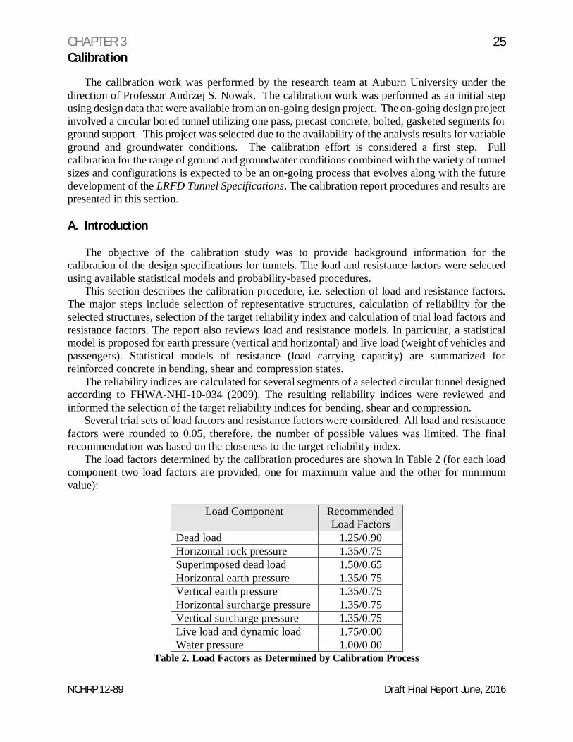
The load factors determined by the calibration procedures are shown in Table 2 (for each loadcomponent two load factors are provided, one for maximum value and the other for minimumvalue):
Load Component RecommendedLoad Factors
Dead load 1.25/0.90Horizontal rock pressure 1.35/0.75Superimposed dead load 1.50/0.65Horizontal earth pressure 1.35/0.75Vertical earth pressure 1.35/0.75Horizontal surcharge pressure 1.35/0.75Vertical surcharge pressure 1.35/0.75Live load and dynamic load 1.75/0.00Water pressure 1.00/0.00
Table 2. Load Factors as Determined by Calibration Process
CHAPTER 3 26Calibration
NCHRP 12-89 Draft Final Report June, 2016
Until more analysis data are available from a more diverse sample of tunnels and ground andgroundwater conditions, it was decided to use the load factors from the AASHTO, LRFD BridgeDesign Specifications in the LRFD Tunnel Specifications.
The calibration report includes eight Sections. After the introduction, Section B provides thedescription of the calibration procedure. The procedure is consistent with the calibration of theAASHTO LRFD Bridge Design Specifications, as documented in NCHRP Report 368 (Nowak1999). Section C covers the load models. For each load component, two parameters wereconsidered: a bias factor, λ, which is the ratio of mean-to-nominal and, , a coefficient of variation.The statistical parameters of the major load components were based on the available literature andprevious research by the research team.
Resistance models are presented in Section D. The load carrying capacity was determined fora circular tunnel. The analysis was performed for several sections and involved consideration ofthe ultimate capacity with regard to bending, shear, and compression. For each limit state thestatistical parameters also included λ and .
The selected reliability analysis procedure is described in Section E. Resistance was consideredas a lognormal random variable and total load effect as a normal random variable. A closed formformula is derived for calculation of the reliability index, .
Reliability indices were calculated for the considered tunnel sections and the results arepresented in tables in Section F. For each of the considered tunnel section, the nominal load valueswere calculated using commercially available structural analysis software. Ground/structureinteraction was included in the models. For each tunnel section, five segments were considered,and reliability indices were calculated for all of them. Nominal resistance was determined usingthe design formula (factored load has to be less than factored resistance). The obtained spectrumof reliability indices was reviewed to prepare a background for the selection of the target reliabilityindex, .
The selection of the target reliability index, is described in Section G. A target reliabilityindex was considered separately for each limit state, i.e. bending, shear, and compression. Then,the load and resistance factors were selected that resulted in reliability indices that were closest tothe target value. The number of possible options was limited because load and resistance factorswere rounded to 0.05. To confirm the validity of the recommended load and resistance factors,reliability indices were calculated and presented in tables.
Chapter 5 of this report contains references for the calibration study.
B. Calibration Procedure
The objective of the calibration is to select the load and resistance factors for tunneldesign. The calibration procedure is consistent with the development of AASHTO LRFD BridgeDesign Specifications (NCHRP Report 368, Calibration of LRFD Bridge Design Code). Theprocedure included the following steps:
Step 1. Review of the available literature and data
The review included previous NCHRP projects, and other studies. An important part of thestudy was to collect and review previous research on statistical parameters of load and resistanceparameters, in particular as related to tunnels.
CHAPTER 3 27Calibration
NCHRP 12-89 Draft Final Report June, 2016
Step 2. Select representative tunnel structures
This report deals with a circular tunnel section only but the recommended load factors are alsoapplicable to box sections. Step 2 involves analysis of the technical drawings, dimensions,identification of structural types, materials, load components, ground conditions, etc. The designdrawings, together with calculated nominal values of load effects (axial loads, bending momentsand shear forces) at various locations around the perimeter of the tunnel were used in the study.The obtained designs were considered as representative for the tunnel structures covered by theLRFD Tunnel Specifications.
For each of the considered components and cross sections, the calculated load values includednominal (design) dead load, live load, earth pressure, water pressure, etc. The resistance (loadcarrying capacity) is calculated using the provisions of the AASHTO LRFD Bridge DesignSpecifications for reinforced concrete and prestressed concrete design. Load components andresistance (bending, shear and compression) are calculated as unfactored nominal (design) values.
The input data for calibration included:
(a) Technical drawings showing general view of the tunnel structure(b) Information about materials (type, grade, strength, etc.)(c) Calculation of nominal values of load components around the circumference of the tunnel(d) Calculation of the nominal load carrying capacity (bending, shear, and compression)(e) Information about the computer procedure used for calculation of design loads
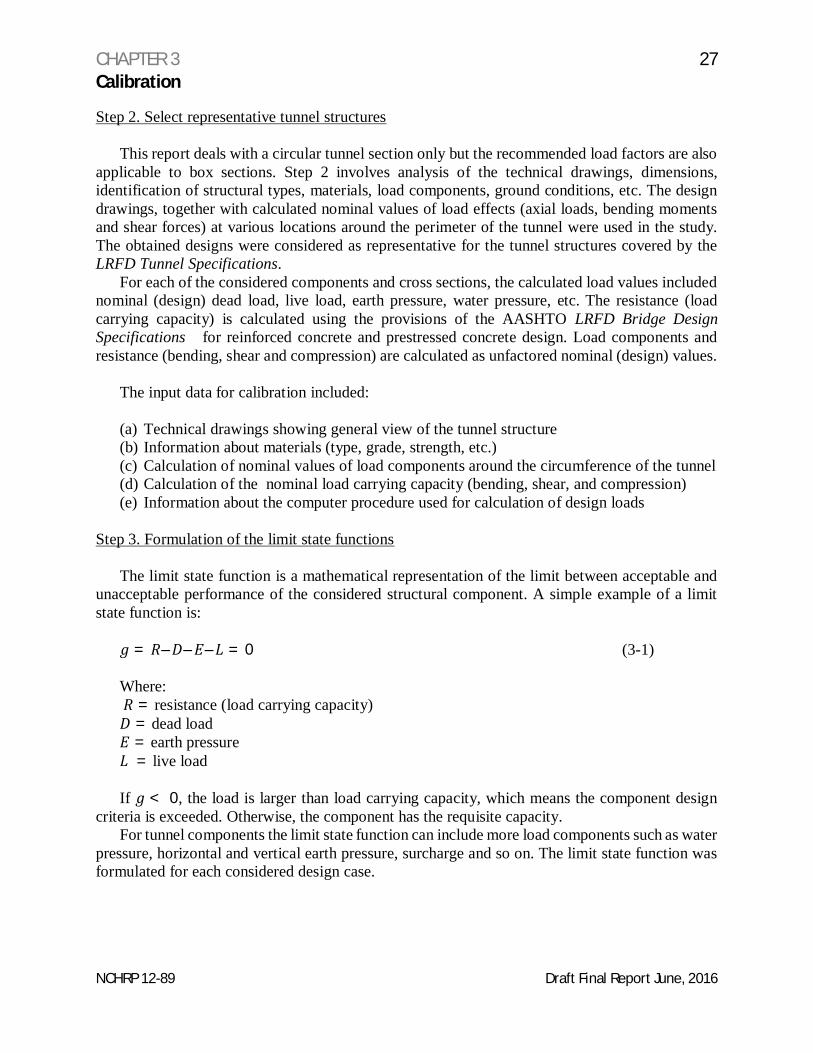
Step 3. Formulation of the limit state functions
The limit state function is a mathematical representation of the limit between acceptable andunacceptable performance of the considered structural component. A simple example of a limitstate function is:
= – – – = 0 (3-1)
Where: = resistance (load carrying capacity)
= dead load= earth pressure = live load
If < 0, the load is larger than load carrying capacity, which means the component designcriteria is exceeded. Otherwise, the component has the requisite capacity.
For tunnel components the limit state function can include more load components such as waterpressure, horizontal and vertical earth pressure, surcharge and so on. The limit state function wasformulated for each considered design case.
CHAPTER 3 28Calibration
NCHRP 12-89 Draft Final Report June, 2016
The circular tunnel structure was divided into several segments and the limit state functionsconsidered:
(a) Bending at each segment(b) Shear at the each segment(c) Compression at each segment
For each case, the load components were identified and a mathematical equation was writtensimilar to Eq. (3-1). These equations were used in the reliability analysis.
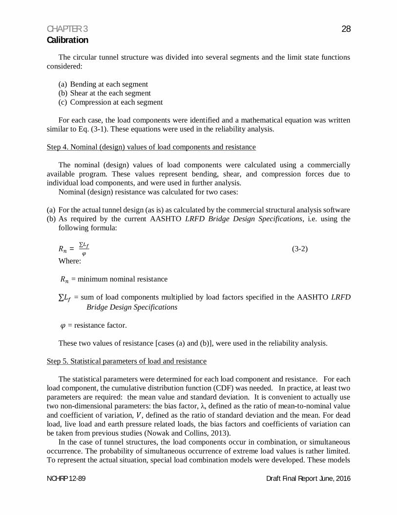
Step 4. Nominal (design) values of load components and resistance
The nominal (design) values of load components were calculated using a commerciallyavailable program. These values represent bending, shear, and compression forces due toindividual load components, and were used in further analysis.
Nominal (design) resistance was calculated for two cases:
(a) For the actual tunnel design (as is) as calculated by the commercial structural analysis software(b) As required by the current AASHTO LRFD Bridge Design Specifications, i.e. using the
following formula:
= ∑ (3-2)Where:
= minimum nominal resistance
∑ = sum of load components multiplied by load factors specified in the AASHTO LRFDBridge Design Specifications
= resistance factor.
These two values of resistance [cases (a) and (b)], were used in the reliability analysis.
Step 5. Statistical parameters of load and resistance
The statistical parameters were determined for each load component and resistance. For eachload component, the cumulative distribution function (CDF) was needed. In practice, at least twoparameters are required: the mean value and standard deviation. It is convenient to actually usetwo non-dimensional parameters: the bias factor, λ, defined as the ratio of mean-to-nominal valueand coefficient of variation, , defined as the ratio of standard deviation and the mean. For deadload, live load and earth pressure related loads, the bias factors and coefficients of variation canbe taken from previous studies (Nowak and Collins, 2013).
In the case of tunnel structures, the load components occur in combination, or simultaneousoccurrence. The probability of simultaneous occurrence of extreme load values is rather limited.To represent the actual situation, special load combination models were developed. These models
CHAPTER 3 29Calibration
NCHRP 12-89 Draft Final Report June, 2016
took into account the fact that when considering load combination, some load components takeaverage values. However, some of the load components can be correlated (they are not independentof each other), for example a horizontal earth pressure on two sides of the tunnel can be almost thesame (but opposite sign). These correlations require a special approach.
Step 6. Reliability analysis procedure
Reliability analysis procedure was selected and adjusted for application to the consideredtunnel structures. Reliability was calculated in terms of the reliability index (Nowak and Collins2013). For example, for the limit state function, the reliability index, , is
= ( ) (3-3)
Where:
, , , are mean values,
and
, , , are standard deviations.
The presence of correlated load components requires a special consideration. The approachwas developed by the research team in the previous studies.
Step 7. Calculation of reliability indices
The reliability indices were calculated for the representative circular tunnel structure for theconsidered design cases and limit states. The calculations were performed for two sets of nominalresistance values as defined in Step 4 above. The resulting reliability indices were treated asrepresentative for the current design (before calibration).
The results are presented in tables and graphs. The results serve as a basis for the calibrationfor tunnels, i.e. selection of the target reliability index and then selection of the load and resistancefactors.
Step 8. Selection of the target reliability index
The results of the reliability analysis serve as a basis for the selection of the target reliabilityindex, . This Step involves the review of calculation results in Step 7. It was expected that therewill be a wide range of values. Selection of the target depends on several considerations. Themost important factors are consequences of failure. This means that if failure to satisfy the limitstate function (i.e. have < 0) is followed by serious consequences, then should be high. Forexample, in the calibration of ACI 318, for columns is 4.0, while for beams is 3.5, becausefailure of columns is considered more serious than failure of beams. Another important
CHAPTER 3 30Calibration
NCHRP 12-89 Draft Final Report June, 2016
consideration is the cost. If reliability can be increased economically, then it is increased, if it isprohibitively expensive, a lower reliability level is used.
In this study, the target reliability index will be consistent with slab design in AASHTO LRFDBridge Design Specifications and ACI 318.
Step 9. Calculation of load and resistance factors
Calculation of load and resistance factors is the final step in the calibration procedure. Forconsistency, the load factors that are not tunnel-specific (e.g. dead load and live load) will beassumed the same as in AASHTO LRFD Bridge Design Specifications. For tunnel-specific loadcomponents, the preliminary values of load factor, , will be determined from the formula
= (1 + ) (3-4)
where is the bias factor and is coefficient of variation of the load component. Parameter canbe taken about 1.8-2.0 for the strength limit states (NCHRP Report 368).
The number of possible values of load factors is limited because they are rounded to the nearest0.05. Therefore, for each load component, further calculations were carried out for three possiblevalues of load factor: one determined from Eq. (3-4), rounded off to the nearest 0.05, and two othervalues larger and smaller by 0.05.
For correlated loads, load combination factors were considered using the approach used inprevious studies.
For each considered set of load factors, the required nominal resistance was calculated fromthe following equation:
= ∑ (3-5)
Where:
= minimum nominal resistance
∑ = sum of load components multiplied by load factors specified in the AASHTO LRFDBridge Design Specifications
and
= resistance factor
Resistance factors for the reinforced concrete wall and roof were taken consistent with theAASHTO LRFD Bridge Design Specifications. For comparison, the reliability analysis was alsoperformed for factors higher and lower by 0.05 than AASHTO LRFD Bridge DesignSpecifications specified values.
Reliability analyses were performed for a wide range of combinations of load factors. Theresults are presented in tables and graphs. The final recommendation as to load and resistancefactors was based on closeness to the target reliability index.
CHAPTER 3 31Calibration
NCHRP 12-89 Draft Final Report June, 2016
Step 10. Final check and presentation of results
The reliability indices were calculated for the recommended set of load and resistance factors.The calibration procedure is documented in this Calibration Report.
C. Load Models
Load Components
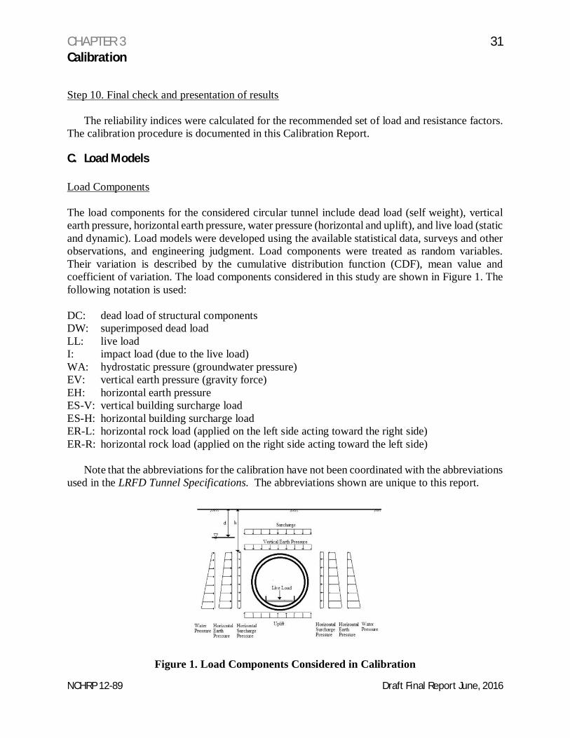
The load components for the considered circular tunnel include dead load (self weight), verticalearth pressure, horizontal earth pressure, water pressure (horizontal and uplift), and live load (staticand dynamic). Load models were developed using the available statistical data, surveys and otherobservations, and engineering judgment. Load components were treated as random variables.Their variation is described by the cumulative distribution function (CDF), mean value andcoefficient of variation. The load components considered in this study are shown in Figure 1. Thefollowing notation is used:
DC: dead load of structural componentsDW: superimposed dead loadLL: live loadI: impact load (due to the live load)WA: hydrostatic pressure (groundwater pressure)EV: vertical earth pressure (gravity force)EH: horizontal earth pressureES-V: vertical building surcharge loadES-H: horizontal building surcharge loadER-L: horizontal rock load (applied on the left side acting toward the right side)ER-R: horizontal rock load (applied on the right side acting toward the left side)
Note that the abbreviations for the calibration have not been coordinated with the abbreviationsused in the LRFD Tunnel Specifications. The abbreviations shown are unique to this report.
Figure 1. Load Components Considered in Calibration
CHAPTER 3 32Calibration
NCHRP 12-89 Draft Final Report June, 2016
The basic load combination for the tunnel structures evaluated is a simultaneous occurrence ofdead load, earth and water pressure, and live load. It was assumed that the economic life time fornewly designed structures is 75 years. Therefore, the extreme values of load components areextrapolated accordingly from the available data base. The statistical parameters of all loadcomponents correspond to 75 year time period. Note that extending the design to 150 years asrecommended in the LRFD Tunnel Specifications has a minimal effect on the load factors.
Nominal values of load components were used in the calibration were determined accordingto the Technical Manual for Design and Construction of Road Tunnels-Civil Elements (2009)FHWA-NHI-10-034 (FHWA Tunnel Manual).
Dead Load (DC)
Dead load, DC, is the gravity load due to the self-weight of the structural and non-structuralelements permanently connected to the structure. The statistical parameters of dead load are =1.05 and = 0.10.
Components of DC are treated as normal random variables. The statistical parameters of deadload are taken as used in the previous bridge code calibration (NCHRP Report 368).
Superimposed Dead Load (DW)
Superimposed dead load is the weight of wearing surface and utilities. Utilities in tunnels caninclude drainage pipes, water supply lines, power lines, signs, signals, lights, tunnel ceilings,finishes, etc. DW is considered as a normal random variable with = 1.03 and the coefficient ofvariation V = 0.08 (Nowak and et.al 2001).
Vertical Earth Pressure (EV)
Buried structures are subjected to vertical and horizontal earth pressures. In many cases, earthpressure is the major load component (up to 90 percent of the total load effect).
Vertical earth pressure, EV, is caused by the self-weight of earth placed on top of a cut-and-cover tunnel or caused by the in situ overburden overlaying a mined or bored tunnel. The actualload depends on the cover depth, h, effective unit weight of material, compacting intensity and thearching ability of the soil in the case of mined or bored tunnels. The statistical parameters of EVinclude a bias factor (mean-to-nominal value) for the earth cover depth = 1.00 and the coefficientof variation V = 0.075 (Nowak and et.al, 2001).
It is assumed that the design (nominal) earth effective unit weight is determined bygeotechnical engineers for each considered location (site-specific). Accordingly, the statisticalparameters for the vertical earth pressure are λ = 1.0 and V = 0.14. Variation of soil cover does notinclude intentional alterations.
Vertical Surcharge (ES-V)
Surcharge, ES-V, represents the effect of building or other stationary structure surcharge loadover the buried structure. The statistical parameters of the surcharge load are equal to: λ = 1.0 andV = 0.15 (Nowak and et.al 2001).
CHAPTER 3 33Calibration
NCHRP 12-89 Draft Final Report June, 2016
Horizontal At-Rest and Active Earth Pressure (EH)
Horizontal (lateral) earth pressure, EH, is a function of the vertical earth load and earthproperties. The actual value depends on construction method, depth of overburden, compactingintensity, and water level. Lateral earth pressure must consider both permanent and temporary(during construction) pressure. For most cases, the at-rest earth pressure coefficient, Ko, canreasonably be assumed to be in the range of 0.5 (EH1) to 1.0 (EH2). The statistical parameters ofEH are assumed λ = 0.95 and V = 0.15.
For active earth pressure the parameters are λ = 0.80 and V = 0.15. These values are based onthe information provided in Nowak and et.al (2001).
Horizontal Surcharge (ES-H)
The horizontal pressure due to surcharge, ES-H, is modeled similarly to horizontal earthpressure. ES-H can potentially occur on one side only. The actual value depends on the K factor,which is a subject to a considerable variation. Therefore, the parameters are λ = 0.95 and V = 0.15.
Hydrostatic Pressure (WA)
Water pressure, WA, depends on the groundwater table in relation to the cover depth, h. Thedensity of water is nominally 62.4 lb/ft3. The major source of uncertainty in estimation of WA isthe depth of the water table. The water table depth can vary with time. Additionally, salinity andother factors can affect the density of the groundwater. The statistical parameters of WA are λ =0.90 and V = 0.15.
Live Load (LL)
The statistical parameters of live load, LL, depend on the tunnel configuration. In this studythey are assumed λ = 1.25 and V=0.18 (NCHRP Report 368).
Horizontal Rock Pressure (ER)
Horizontal rock pressure, ER, can be applied to both sides of the structure (ER-R, which isapplied on the right side acting toward the left side, and ER-L, which is applied on the left sideacting toward the right side). The bias factor of the horizontal rock pressure is, λ = 1.0, and thecoefficient of variation of rock pressure can be considered as smaller than that of earth pressure,V = 0.12 (Nowak and et.al 2001).
For the purpose of this report, it is assumed that the loads acting on two opposite sides arealmost fully correlated. The coefficient of correlation is taken as 0.95. This may not be the casedepending on the ground conditions, but further refinement is recommended for future research.
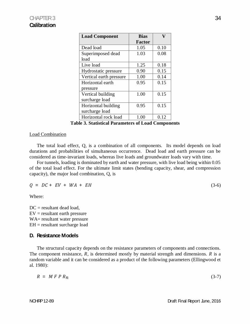
Table 3 provides a summary of the statistical parameters described above for each of the loadcomponents.
Horizontal rock load 1.00 0.12Table 3. Statistical Parameters of Load Components
Load Combination
The total load effect, Q, is a combination of all components. Its model depends on loaddurations and probabilities of simultaneous occurrence. Dead load and earth pressure can beconsidered as time-invariant loads, whereas live loads and groundwater loads vary with time.
For tunnels, loading is dominated by earth and water pressure, with live load being within 0.05of the total load effect. For the ultimate limit states (bending capacity, shear, and compressioncapacity), the major load combination, Q, is
= + + + (3-6)
Where:
DC = resultant dead load,EV = resultant earth pressureWA= resultant water pressureEH = resultant surcharge load
D. Resistance Models
The structural capacity depends on the resistance parameters of components and connections.The component resistance, , is determined mostly by material strength and dimensions. is arandom variable and it can be considered as a product of the following parameters (Ellingwood etal. 1980):
= (3-7)
CHAPTER 3 35Calibration
NCHRP 12-89 Draft Final Report June, 2016
Where:
= material factor representing properties such as strength, modulus of elasticity, crackingstress, and chemical composition
= fabrication factor including geometry, dimensions, and section modulus
= analysis factor such as approximate method of analysis, idealized stress and straindistribution model.
= minimum nominal resistance
The variation of resistance has been modeled by tests, simulations, observations of existingstructures, and by engineering judgment. The statistical parameters are developed for reinforcedconcrete slabs and beams (Nowak and Rakoczy (2012a). Shear resistance is calculated using themodified compression field theory (Nowak and Rakoczy (2012b).
Bias factors and coefficients of variation are determined for material factor, , fabricationfactor, F, and analysis factor, . Factors and are combined. The parameters of R are calculatedas follows:
= ( )( ) (3-8)
Where:
= bias factor of R = bias factor of FM
= bias factor of P
The coefficient of variation of R is calculated as follow.
= + (3-9)
Where:
VR = coefficient of variation ofVFM = coefficient of variation ofVP = coefficient of variation of
The validity of the procedure was checked by comparison of parameters (material propertiesand dimensions), and analytical models. It was concluded that the results are applicable to tunnelstructures.
Statistical data on material and dimensions used in a previous report (NCHRP Report 368)were based on the available literature.
CHAPTER 3 36Calibration
NCHRP 12-89 Draft Final Report June, 2016
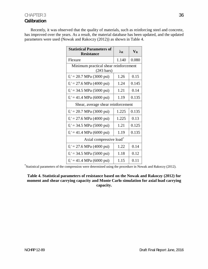
Recently, it was observed that the quality of materials, such as reinforcing steel and concrete,has improved over the years. As a result, the material database has been updated, and the updatedparameters were used (Nowak and Rakoczy (2012)) as shown in Table 4.
fc' = 41.4 MPa (6000 psi) 1.15 0.11*Statistical parameters of the compression were determined using the procedure in Nowak and Rakoczy (2012).
Table 4. Statistical parameters of resistance based on the Nowak and Rakoczy (2012) formoment and shear carrying capacity and Monte Carlo simulation for axial load carrying
capacity.
CHAPTER 3 37Calibration
NCHRP 12-89 Draft Final Report June, 2016
E. Reliability Analysis
Limit States
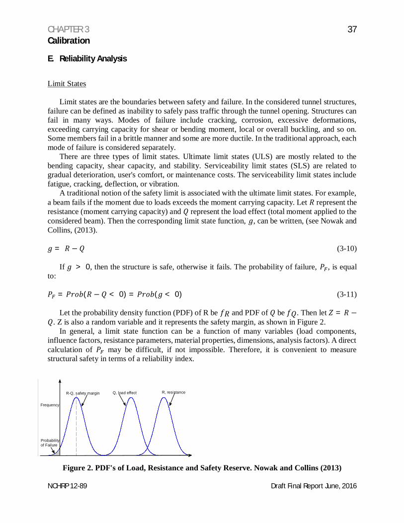
Limit states are the boundaries between safety and failure. In the considered tunnel structures,failure can be defined as inability to safely pass traffic through the tunnel opening. Structures canfail in many ways. Modes of failure include cracking, corrosion, excessive deformations,exceeding carrying capacity for shear or bending moment, local or overall buckling, and so on.Some members fail in a brittle manner and some are more ductile. In the traditional approach, eachmode of failure is considered separately.
There are three types of limit states. Ultimate limit states (ULS) are mostly related to thebending capacity, shear capacity, and stability. Serviceability limit states (SLS) are related togradual deterioration, user's comfort, or maintenance costs. The serviceability limit states includefatigue, cracking, deflection, or vibration.
A traditional notion of the safety limit is associated with the ultimate limit states. For example,a beam fails if the moment due to loads exceeds the moment carrying capacity. Let represent theresistance (moment carrying capacity) and represent the load effect (total moment applied to theconsidered beam). Then the corresponding limit state function, , can be written, (see Nowak andCollins, (2013).
= − (3-10)
If > 0, then the structure is safe, otherwise it fails. The probability of failure, , is equalto:
= ( − < 0) = ( < 0) (3-11)
Let the probability density function (PDF) of R be and PDF of be . Then let = −. Z is also a random variable and it represents the safety margin, as shown in Figure 2.
In general, a limit state function can be a function of many variables (load components,influence factors, resistance parameters, material properties, dimensions, analysis factors). A directcalculation of may be difficult, if not impossible. Therefore, it is convenient to measurestructural safety in terms of a reliability index.
Figure 2. PDF's of Load, Resistance and Safety Reserve. Nowak and Collins (2013)
Q, load effect R, resistance
Probabilityof Failure
Frequency
R-Q, safety margin
CHAPTER 3 38Calibration
NCHRP 12-89 Draft Final Report June, 2016
Reliability Index
The reliability index, , is defined as a function of , the calculation procedure of thereliability index was described by Nowak and Collins (2013) as follows:
= −Ф (3-12)
where Ф = inverse standard normal distribution function. Examples of 's and corresponding's are shown in Table 5.
There are several procedures available for the calculation of . These procedures vary withregard to accuracy, required input data, and computing effort.
The simplest case involves a linear limit state function (Eq. 3-9). If both and areindependent (in the statistical sense), normal random variables, then the reliability index is,
= (3-13)
Where:
= mean of = mean of
= standard deviation of R = standard deviation of .
If both and are lognormal random variables, then can be approximated by:
=
(3-14)
Where:
= coefficient of variation of R = coefficient of variation of .
A different formula is needed of coefficients of variation are larger than 0.2.
Eq. (3-13) and (3-14) require the knowledge of only two parameters for each random variable: themean and standard deviation (or coefficient of variation). Therefore, the formulas belong to thesecond moment methods. If the parameters and are not both normal and lognormal, then theformulas give only an approximate value of . In such a case, the reliability index can be calculatedusing the Rackwitz and Fiessler (1978) procedure, sampling techniques, or by Monte Carlosimulations.
CHAPTER 3 39Calibration
NCHRP 12-89 Draft Final Report June, 2016
Reliability index β Reliability S ( = 1 - Pf ) Probability of Failure
0.0 0.50 0.500×10+0
0.5 0.691 0.309×10+0
1.0 0.841 0.159×10+0
1.5 0.933 2 0.668×10⁻¹
2.0 0.977 2 0.228×10⁻¹
2.5 0.993 79 0.621×10⁻²
3.0 0.998 65 0.135×10⁻²
3.5 0.999 767 0.233×10⁻³
4.0 0.999 968 3 0.317×10⁻⁴
4.5 0.999 996 60 0.340×10⁻⁵
5.0 0.999 999 713 0.287×10⁻⁶
5.5 0.999 999 981 0 0.190×10⁻⁷
6.0 0.999 999 999 013 0.987×10⁻⁹
6.5 0.999 999 999 959 8 0.402×10⁻¹⁰
7.0 0.999 999 999 998 72 0.128×10⁻¹¹
7.5 0.999 999 999 999 9681 0.319×10⁻¹³
8.0 0.999 999 999 999 999 389 0.611×10⁻¹⁵
Table 5. Probability of Failure vs. .
Reliability Methods used in this Calibration
The statistical parameters of load and resistance are determined on the basis of the availabledata, simulations, and engineering judgment. The techniques used in this study include MonteCarlo and the procedure developed by Nowak et.al (1987).
The reliability is measured in terms of the reliability index. It is assumed that the total load, ,is a normal random variable. The resistance is considered as a lognormal random variable.
For the given nominal (design) value of resistance, , the procedure used to calculate thereliability index, , is outlined below.
1. Given: resistance parameters: , ,
load parameters: ,
2. Calculate the mean resistance, =3. Assume the design point is:
∗ = (1 − k ) (3-15)
where k is unknown.
CHAPTER 3 40Calibration
NCHRP 12-89 Draft Final Report June, 2016
Take = 2 (initial guess), and calculate
∗ = (1 − 2 ).
4. Value of the cumulative distribution function of R (lognormal), and the probability densityfunction of , for ∗are,
( ∗) = ( ∗) ( ) (3-16)
( ∗) =
( ∗)
( ∗)(3-17)
5. Calculate the argument of function and ,
= ( ∗) ( ) (3-18)
6. Calculate the standard deviation and mean of the approximating normal distribution of , at ∗,
= ( )( )∗
= ∗ (3-19)
= ∗ − [ ( )] = ∗ −(3-20)
The load, , is normally distributed: therefore, the mean and standard deviation are and .
7. Calculate the reliability index, ,
=∗ ∗
( ∗)(3-21)
8. Calculate new design point,
∗ = ( ∗)
( ∗)(3-22)
9. Check if the new design point is different than what was assumed in Step 3. If the same, thecalculation of is completed, otherwise go to step 4 and continue. In practice, the reliabilityindex can be obtained in one cycle of iterations.
CHAPTER 3 41Calibration
NCHRP 12-89 Draft Final Report June, 2016
The formula for reliability index can be expressed in terms of the given data ( , , , , )and parameter . By replacing ∗ with (1 − ), a with Eq. (3-22), after somerearrangements, the formula can be presented as,
= ( )[ ( )]
[ ( )] (3-24)
F. Reliability Indices for Tunnels
Selected Structures
The code calibration is based on calculations performed for a single tunnel structureconstructed in varying ground conditions with different cover. Table 6 shows the ground coverover the tunnel. Although the cover over the tunnel is the same at some sections, the groundconditions, hence the load effects in the tunnel lining vary.
The basic design requirement according to the FHWA Tunnel Manual is given by the formulain Eq. (3-1). The reliability indices are calculated for reinforced concrete slabs and the limit states(moment, shear, and compression) described by the representative load components and resistance.
For the selected structures, moments, shears, and compression are calculated due to appliedload. Nominal (design) values can be calculated using the FHWA Technical Manual. The meanmaximum 75 year values of loads are obtained using the statistical parameters presented in Table3. Resistance is calculated in terms of the moment carrying capacity, shear capacity, and axialload carrying capacity. For each case, the minimum required resistance, , is calculated asthe minimum R which satisfies the FHWA Technical Manual. For given loads, , the minimumrequired resistance, , according to FHWA Technical Manual, can be calculated as follows:(Nowak and Collins 2013)
= (∑ )/ (3-24)
CHAPTER 3 42Calibration
NCHRP 12-89 Draft Final Report June, 2016
where are load factors. The load factors specified in the Tunnel Manual are listed in Table 7.In the Tunnel Manual, the resistance factor for reinforced concrete is = 0.90formoment,
= 0.85 for shear, and = 0.75forcompression. The reliability indices are calculated formoment, shear, and compression. For each considered case, the listed parameters include: the meantotal load, , standard deviation of total load, , nominal (design) value of resistance, , andthe reliability index, . Bias factors for resistance for various cases are listed Table 3.
LoadCombination
DC DW EHEV
ES EL LL,IM
WA TU, CR,SH
TG
Min/max Max Min Max Min Max Min Max Min Max MinStrength I 1.25 0.90 1.5 0.65 1.35 0.90 1.5 075 1.00 1.75 1.00 1.20 0.5 0.00
Table 7. Load Factors Specified in Tunnel Manual
Reliability Indices for Tunnels
In order to compute the reliability indices, the tunnels are divided into five segmentscorresponding to the precast concrete segments that make up the tunnel lining (see Figure 3). It isassumed that each segment is designed to resist the maximum moment, shear, and axial load withinthe considered segment.
The nominal resistance is determined using the factored loads, with load factors from theTechnical Manual. Then, using the statistical parameters of load and resistance, the reliabilityindices were calculated for all the cross sections and the eight stations listed in Table 6. For eachcase, the calculations were performed for three vales of a resistance factor: one was taken asspecified in the Technical Manual, and two other values, one larger by 0.05 and the other onesmaller by 0.05.
The reliability indices for the moment carrying capacity, calculated using the current loadfactors specified in Tunnel Manual, are shown in Tables 8 through 10.
CHAPTER 3 43Calibration
NCHRP 12-89 Draft Final Report June, 2016
Figure 3. Considered Segments in the Tunnel Cross Section
Table 13. Reliability indices for the shear capacity based on the Technical Manual,= .
CHAPTER 3 51Calibration
NCHRP 12-89 Draft Final Report June, 2016
Figure 5. The reliability indices for shear and different values of resistance factor,with load factors from the FHWA Technical Manual
The reliability indices for the compression load carrying capacity based on the current loadfactors in Tunnel Manual are shown in Tables 13 through 14.
Table 16. Reliability indices for the compression capacity based on the Technical Manual= .
CHAPTER 3 55Calibration
NCHRP 12-89 Draft Final Report June, 2016
Figure 6. The reliability indices for compression and different values of resistancefactor, with load factors from the Technical Manual
Based on the review of the obtained reliability indices, the target reliability indices can beselected. Since the considered tunnel sections perform adequately, it can be concluded that theacceptable reliability indices can be considered at the lower tail of the cumulative distributionfunction (CDF) in Figures 4 through 6. Therefore, the proposed target reliability indices are aslisted in Table 17.
Load EffectMoment 4.75
Shear 3.50Compression 5.0
Table 17. Proposed Target Reliability
As can be seen, in Figure 4 through 6, by decreasing the resistance factor, the reliability indicesare increased. To obtain a more uniform spectrum of reliability indices, some adjustment of loadfactors were considered. The recommended set of load factors is shown in Table 18.
The reliability indices for the moment carrying capacity using the proposed load factorsspecified in Tunnel Manual are shown in Tables 19 through 21.
LoadCombination
DC EHR DW EHEV
ES LL,IM
WA
Min/max Max Min Max Min Max Min Max Min Max MinStrength I 1.25 0.90 1.35 0.75 1.5 0.65 1.35 0.75 1.35 075 1.75 1.00
Table 27. Reliability indices for compression capacity based on the proposed load factors= .
CHAPTER 3 67Calibration
NCHRP 12-89 Draft Final Report June, 2016
Figure 9. The reliability indices for compression and different values of resistance factor,using the proposed load factors
A comparison of the reliability indices obtained for the design using the load and resistance factorsspecified in the Tunnel Manual and the proposed load factors is shown in Figures 10 through 12for moment, shear, and compression, respectively.
CHAPTER 3 68Calibration
NCHRP 12-89 Draft Final Report June, 2016
Figure 10. Reliability Indices calculated for the load factors in the Tunnel Manual and theproposed load factors, moment carrying capacity
Figure 11. Reliability Indices calculated for the load factors in the Tunnel Manual and the proposedload factors, shear carrying capacity
CHAPTER 3 69Calibration
NCHRP 12-89 Draft Final Report June, 2016
Figure 12. Reliability Indices calculated for the load factors in the Tunnel Manual and theproposed load factors, axial compression carrying capacity
CHAPTER 3 70Calibration
NCHRP 12-89 Draft Final Report June, 2016
The comparison of the cumulative distribution functions of reliability indices corresponding tothe load factors in the Tunnel Manual and the proposed load factors, indicates that the latter resultin a visibly reduced variation.
G. Calibration Conclusions
The reliability-based calibration involved the selection and derivation of the target reliabilityindices and corresponding load and resistance factors. The selected target reliability indices andcorresponding factors are listed in Table 28.
Load EffectMoment 0.90 4.75
Shear 0.85 3.50Compression 0.75 5.0
Table 28. Selected Target Reliability Indices and f factors
The load factors resulting from the calibration process are shown in Table 29.
Load Component Recom-mended
LoadFactors
Dead load 1.25/0.90Horizontal rock pressure 1.35/0.75Superimposed dead load 1.50/0.65Horizontal earth pressure 1.35/0.75Vertical earth pressure 1.35/0.75Horizontal surcharge pressure 1.35/0.75Vertical surcharge pressure 1.35/0.75Live load and dynamic load 1.75/0.00Water pressure 1.00/0.00
Table 29. Calibration Process Load Factors
Reliability indices were calculated using these proposed load factors and factors from theTechnical Manual. For comparison, the average values of b were also calculated for the loadfactors from the Technical Manual. In addition, the calculations were also performed for +0.05and –0.05. The results are shown in Table 30.
Table 30. Average target reliability indices for load factors in the Tunnel Manual (Old) andproposed load factors (Proposed)
CHAPTER 4 72Conclusions and Suggested Research
NCHRP 12-89 Draft Final Report June, 2016
A. Conclusions
During the conduct of the research and as a result of the comments and discussions thatoccurred during the industry review meetings, the following issues will require further attentionand discussion within the tunnel community as the draft specifications are implemented by thedesign and construction industry:
1. An extensive planning phase study should be undertaken to define the configuration, alignmentand system requirements for the proposed tunnel. Once these decisions are made, then thedesign can progress utilizing the LRFD Tunnel Specifications.
2. Tunnel internal dimensions and features have to be balanced with initial costs and life cyclecosts. The larger the opening, the greater the initial cost. However, larger openings canprovide for lower life cycle costs and increased safety. Safe spaces for inspectors andmaintenance personnel can reduce user costs. Walkways and egress pathways enhance safetyfor users. Increased vertical clearance reduces the risk for damage from over-height vehiclesand provides space for future overlays of waring course. These factors, and many others shouldbe considered during the planning phase.
3. The LRFD Tunnel Specifications were developed through a collaborative effort betweenowners and designers. The specifications were developed to provide owners with as muchflexibility as possible while also providing minimum standards for the design of tunnel civiland system elements.
4. The inclusion by reference of design specifications required careful examination of thereferenced specifications not only for design provisions, but also for definitions, notations andabbreviations. Definitions, notations and abbreviations were reviewed to be sure they wereused identically in both specifications. New definitions, notations and abbreviations weredeveloped for use in the LRFD Tunnel Specifications when required, however, wheneverpossible, the same definitions, notations and abbreviations in the referenced specificationswere used in the LRFD Tunnel Specifications. Designers using the LRFD TunnelSpecifications will require a detailed careful review of both sets of specifications to becomefamiliar with the information and how it is referenced and used.
5. Industry consensus on the design life of tunnels is an unresolved issue. Reaching thisconsensus would be a daunting task. Alternately, individual owners could determine designlives for their projects. As with the current LRFD Bridge Design Specifications, states andmunicipalities can adopt modifications to the LRFD Tunnel Specifications to dictate designpreferences, tighten or loosen requirements or delete provisions. The design life has a nominalimpact on the initial cost of the tunnel when considering load effects.
6. When considering the durability of materials, there is some lack of uniformity with regard tothe determination of the service life. Some materials, for example gaskets for segmental tunnellinings, have not been in use for the length of time being specified for the service life.
CHAPTER 4 73Conclusions and Suggested Research
NCHRP 12-89 Draft Final Report June, 2016
Additional data need to be acquired to determine the viability of materials and components toremain in service for the durations expected.
7. The applicability of the LRFD Tunnel Specifications to the repair or rehabilitation of existingtunnels need to be considered on a case-by-case basis as projects are identified. It may not beeconomically feasible to retrofit existing tunnels to meet the requirements of the LRFD TunnelSpecifications. This is especially true with regard to tunnel ventilation systems. Agrandfathering process for existing tunnels should be investigated.
8. The LRFD Tunnel Specifications are not nor were they intended to be an instructional tool fortunnel design. The specifications are intended to be used by experienced tunnel designers.
9. Project specific design criteria are required for tunnel projects. The LRFD TunnelSpecifications, if adopted for use on a specific tunnel project, would be a component of thedesign criteria.
10. The tunnel ventilation system can be a very expensive component of a tunnel project. Designfires for use in the design of ventilation systems and fire protection should be developedspecifically for each tunnel project. The design fire will drive the cost of the ventilation systemand a one size fits all solution to this issue is not appropriate.
11. The design earthquake is an owner preference parameter. Recommendations are given in theLRFD Tunnel Specifications, but this is an issue that may require additional research orcaucusing to resolve.
12. The AASHTO LRFD Bridge Design Specifications were used to the greatest extent possible.As such, some of the LRFD Tunnel Specification provisions appear to be isolated andunrelated. This was clarified within the specifications and associated commentary, but willrequire careful application of the provisions when combining the two specifications. The bestexample of this is in the development of apparent earth pressures for cut-and-cover tunnelstructures. A common construction technique for minimizing the footprint of cut-and-covertunnel construction is to use the support of excavation walls for both the temporary open cutconditions and the final structural walls in the completed condition. The AASHTO LRFDBridge Design Specifications provide a thorough treatment of the permanent condition, butprovisions for the design of the temporary conditions had to be developed for inclusion in theLRFD Tunnel Specifications.
13. The research performed under NCHRP 12-89 advanced the work contained in AASHTO’sTechnical Manual for Design and Construction of Road Tunnels – Civil Elements. Thisdocument should be updated to bring it into alignment with the LRFD Tunnel Specifications.
CHAPTER 4 74Conclusions and Suggested Research
NCHRP 12-89 Draft Final Report June, 2016
B. Suggested Research
Shafts:
Shafts are common elements in tunnel projects. Shafts are vertical elements that connect thetunnel to the surface. Typical uses for shafts include ventilation and emergency egress.
The design of shafts is not included in the LRFD Tunnel Specifications. Additional researchto develop design specification provision for shafts should be performed for inclusion in futureeditions.
Jacked Boxes:
Jacked boxes is a construction technique used to build low cover tunnels under existingfeatures such as railroads or highways. A concrete box of a size sufficient to enclose the proposedtunnel opening is constructed adjacent to the feature being crossed. The box is then jacked intothe ground under the feature. Excavation of the ground occurs from inside the box as it is advancedunder the feature being crossed.
The design of jacked boxes is not included in the LRFD Tunnel Specifications. Additionalresearch to develop design specification provision for shafts should be performed for inclusion infuture editions.
Pipe Arches:
Pipe arches are a tunnel construction methodology that utilizes a series of parallel smalldiameter pipes jacked or bored in a configuration that forms an arched canopy over the requiredtunnel opening. The soil beneath the canopy is excavated after the pipes are in place to create therequired opening.
The design of pipe arches is not included in the LRFD Tunnel Specifications. Additionalresearch to develop design specification provision for pipe arches should be performed forinclusion in future editions.
Construction Specifications:
A listing of construction specification sections for civil elements of tunnel projects has beenincluded as an appendix. These specification sections should be fully developed and integratedwith the AASHTO LRFD Bridge Construction Specifications. In addition, constructionspecifications for tunnel system elements should also be developed in the LRFD format.
Calibration:
The calibration work performed under this research should be continued and expanded to alltunnel construction methodologies. Various tunnel geometries should be investigated and acomprehensive refinement of load and resistant factors be developed.
CHAPTER 4 75Conclusions and Suggested Research
NCHRP 12-89 Draft Final Report June, 2016
Tunnel Size:
With the ever increasing size requirements for tunnels, the effects of scale should beinvestigated to ensure that the recommended design provisions can be safely scaled to theincreasing tunnel opening dimensions.
Americans with Disabilities Act Provisions (ADA):
The question of ADA compliance in road tunnels, specifically with regard to emergency egressis a topic that requires additional research. Providing ADA complaint egress pathways can conflictwith providing traffic safe tunnel configurations. During a traffic incident, there is no way topredict what pathways may be blocked as a result of an incident, making defined egress pathsdifficult to delineate. Egress during an incident inside a tunnel is a difficult issue to address.Motorists are not trained to utilize emergency exits, providing direction to motorists inside a tunnelis difficult and individual behavior during an emergency is not always predictable. Signing foremergency exits is the topic of current research and should include ADA requirements.
Tunnels that have pedestrian walkways, separated from traffic by physical barriers, should beevaluated for ADA accessibility. Provisions were not implicitly included in the LRFD TunnelSpecifications in order to provide owners the flexibility to address this issue on a case-by-casebasis.
For this project, it was decided to remain silent on this topic and instead make reference toNFPA 502 which in turn invokes NFPA 101. NFPA 101 provides guidance for accessibility ofegress pathways. Owners can elect to adopt all or part of NFPA and then decide how to addressthe question of ADA compliance.
Over-Height Vehicles:
Over-height vehicles can cause damage to tunnel portals and interiors, as well as create safetyconcerns when they bypass warning devices. Various concepts exist for limiting the damagecaused by over height vehicles. These concepts include reducing the tunnel height at the portal toprevent these vehicle from entering the tunnel. The configuration and design parameters forcapturing vehicles while protecting vehicle occupants requires additional study.
CHAPTER 5 76References
NCHRP 12-89 Draft Final Report June, 2016
1. AASHTO, “Bridge Design Specifications, (7th Edition.),” American Association of StateHighway and Transportation Officials, Washington D.C,, 2014.
2. ACI 318-08, “Building Code Requirements for Structural Concrete,” American ConcreteInstitute, Farmington Hills, Michigan, 2008.
3. Ellingwood, B. Galambos, T.V., MacGregor, J.G. and Cornell C.A., "Development of aProbability Based Load Criterion for American National Standard A58", National Bureauof Standards, NBS Special Publication 577, Washington, D.C., 1980.
4. Nowak, Andrzej S. and Rakoczy, Anna M., “Reliability-Based Calibration of Design Codefor Concrete Structures (ACI 318)” published in Proceeding of the IBRACON, the 54th
CBC (Brazilian Conference on Concrete), Maceio, Alagoas-Brail, 2012.
5. Nowak, A. S., Collins K. R., “Reliability of Structures”, CRC Press, New York, 2013.
6. Nowak Andrzej S. and Rakoczy, Anna M., “Statistical Resistance Models for R/CStructural Components”, ACI SP-284-6, Vol. 248, 2012, pp. 1-16.
7. Nowak, A.S., Rakoczy, A. M., “Statistical Parameters for Compressive Strength ofLightweight Concrete”, Concrete Bridge Conference: Achieving Safe, Smart, andSustainable Bridges, February 2010.
8. Nowak, A.S., “Calibration of LRFD Bridge Design Code”, NCHRP Report 368,Transportation Research Board, Washington, D.C., 1999.
9. Nowak, A.S., Park, C-H, and Ojala, P., “Calibration of Design Code for Buried Structures”,Canadian Journal of Civil Engineering, V. 28, No. 4, 2001, pp. 574-582.
10. Nowak, A.S., Czernecki, J., Zhou, J. and Kayser, R., "Design Loads for Future Bridges",Report UMCE 87-1, University of Michigan, Ann Arbor, MI 1987.
11. Rackwitz, R. and Fiessler, B., "Structural Reliability Under Combined Random LoadSequences", Computer and Structures, 9, 1978, pp. 489-494.
12. U.S. Department of Transportation Federal Highway Administration, “Technical Manualfor Design and Construction of Road Tunnels-Civil Elements”, report No. FHWA-NHI-10-034, 2009.
ACRONYMS
NCHRP 12-89 Draft Final Report June, 2016
AASHTO – American Association of State Highway and Transportation OfficialsACI – American Concrete InstituteAISC – American Institute of Steel ConstructionAMCA – Air Movement Control Association International, Inc.ANSI/IES – American National Standards Institute / Illuminating Engineering SocietyAHSRAE – American Society of Heating Refrigerating and Air-Conditioning EngineersASCE – American Society of Civil EngineersIBC – International Building CodeIEC – International Electric CodeITA – International Tunneling AssociationLRFD – Load and Resistance Factor DesignNCHRP – National Cooperative Highway Research ProgramNFPA – National Fire Protection AssociationSCOBS – Subcommittee for Bridges and StructuresU.S. – United States