Document Format Revision (10/19/11) SCOPE OF WORK FIRE SUPPRESSION, HVAC AND ALARM SYSTEMS Office of Weights and Measures Woodbridge, Middlesex County, N.J. PROJECT NO. S0550-00 STATE OF NEW JERSEY Honorable Chris Christie, Governor Honorable Kim Guadagno, Lt. Governor DEPARTMENT OF THE TREASURY Andrew P. Sidamon-Eristoff, Treasurer DIVISION OF PROPERTY MANAGEMENT AND CONSTRUCTION Steven Sutkin, Director Date: November 21, 2011
Transcript
Document Format Revision (10/19/11)
SCOPE OF WORK
FIRE SUPPRESSION, HVAC AND ALARM SYSTEMS
Office of Weights and Measures
Woodbridge, Middlesex County, N.J.
PROJECT NO. S0550-00
STATE OF NEW JERSEY
Honorable Chris Christie, Governor
Honorable Kim Guadagno, Lt. Governor
DEPARTMENT OF THE TREASURY Andrew P. Sidamon-Eristoff, Treasurer
DIVISION OF PROPERTY MANAGEMENT AND CONSTRUCTION
Steven Sutkin, Director
Date: November 21, 2011
PROJECT NAME: Fire Suppression, HVAC and Alarm Systems
PROJECT LOCATION: Office of Weights and Measures
PROJECT NO: S0550-00
DATE: November 21, 2011
PAGE 2
TABLE OF CONTENTS
SECTION PAGE
I. OBJECTIVE ...........................................................................................7
II. CONSULTANT QUALIFICATIONS ..................................................7
A. CONSULTANT & SUB-CONSULTANT PRE-QUALIFICATIONS
III. PROJECT BUDGET ..............................................................................7
A. CONSTRUCTION COST ESTIMATE (CCE)
B. CURRENT WORKING ESTIMATE (CWE)
C. COST ESTIMATING
D. CONSULTANT'S FEES
IV. PROJECT SCHEDULE .........................................................................9
A. SCOPE OF WORK DESIGN & CONSTRUCTION SCHEDULE
B. CONSULTANT'S PROPOSED DESIGN & CONSTRUCTION SCHEDULE
C. CONSULTANT DESIGN SCHEDULE
D. BID DOCUMENT CONSTRUCTION SCHEDULE
E. CONTRACTOR CONSTRUCTION PROGRESS SCHEDULE
V. PROJECT SITE LOCATION & TEAM MEMBERS ..................... 11
A. PROJECT SITE ADDRESS
B. PROJECT TEAM MEMBER DIRECTORY
1. DPMC Representative
2. Client Agency Representative
VI. PROJECT DEFINITION .................................................................... 12
A. BACKGROUND
B. FUNCTIONAL DESCRIPTION OF THE BUILDING
PROJECT NAME: Fire Suppression, HVAC and Alarm Systems
PROJECT LOCATION: Office of Weights and Measures
PROJECT NO: S0550-00
DATE: November 21, 2011
PAGE 3
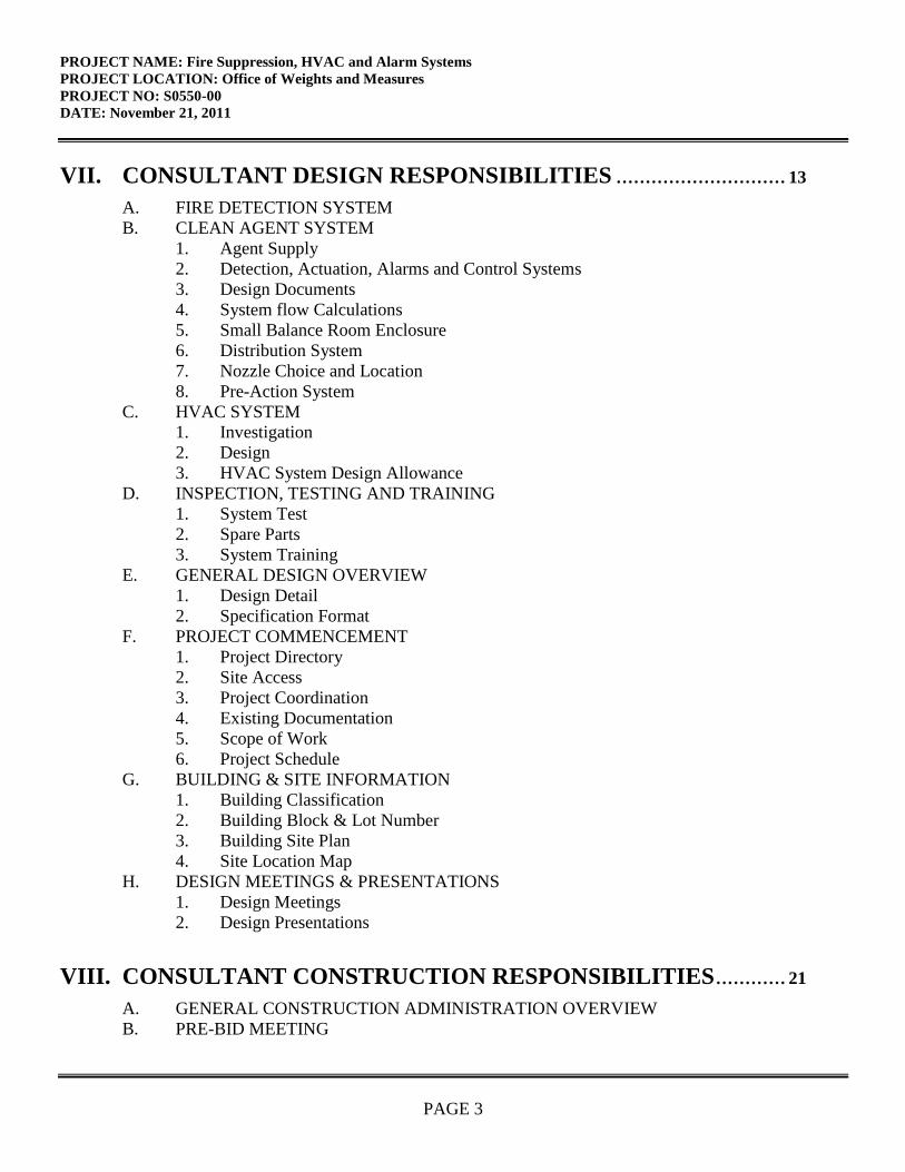
VII. CONSULTANT DESIGN RESPONSIBILITIES ............................. 13
A. FIRE DETECTION SYSTEM
B. CLEAN AGENT SYSTEM
1. Agent Supply
2. Detection, Actuation, Alarms and Control Systems
3. Design Documents
4. System flow Calculations
5. Small Balance Room Enclosure
6. Distribution System
7. Nozzle Choice and Location
8. Pre-Action System
C. HVAC SYSTEM
1. Investigation
2. Design
3. HVAC System Design Allowance
D. INSPECTION, TESTING AND TRAINING
1. System Test
2. Spare Parts
3. System Training
E. GENERAL DESIGN OVERVIEW
1. Design Detail
2. Specification Format
F. PROJECT COMMENCEMENT
1. Project Directory
2. Site Access
3. Project Coordination
4. Existing Documentation
5. Scope of Work
6. Project Schedule
G. BUILDING & SITE INFORMATION
1. Building Classification
2. Building Block & Lot Number
3. Building Site Plan
4. Site Location Map
H. DESIGN MEETINGS & PRESENTATIONS
1. Design Meetings
2. Design Presentations
VIII. CONSULTANT CONSTRUCTION RESPONSIBILITIES ............ 21
A. GENERAL CONSTRUCTION ADMINISTRATION OVERVIEW
B. PRE-BID MEETING
PROJECT NAME: Fire Suppression, HVAC and Alarm Systems
PROJECT LOCATION: Office of Weights and Measures
PROJECT NO: S0550-00
DATE: November 21, 2011
PAGE 4
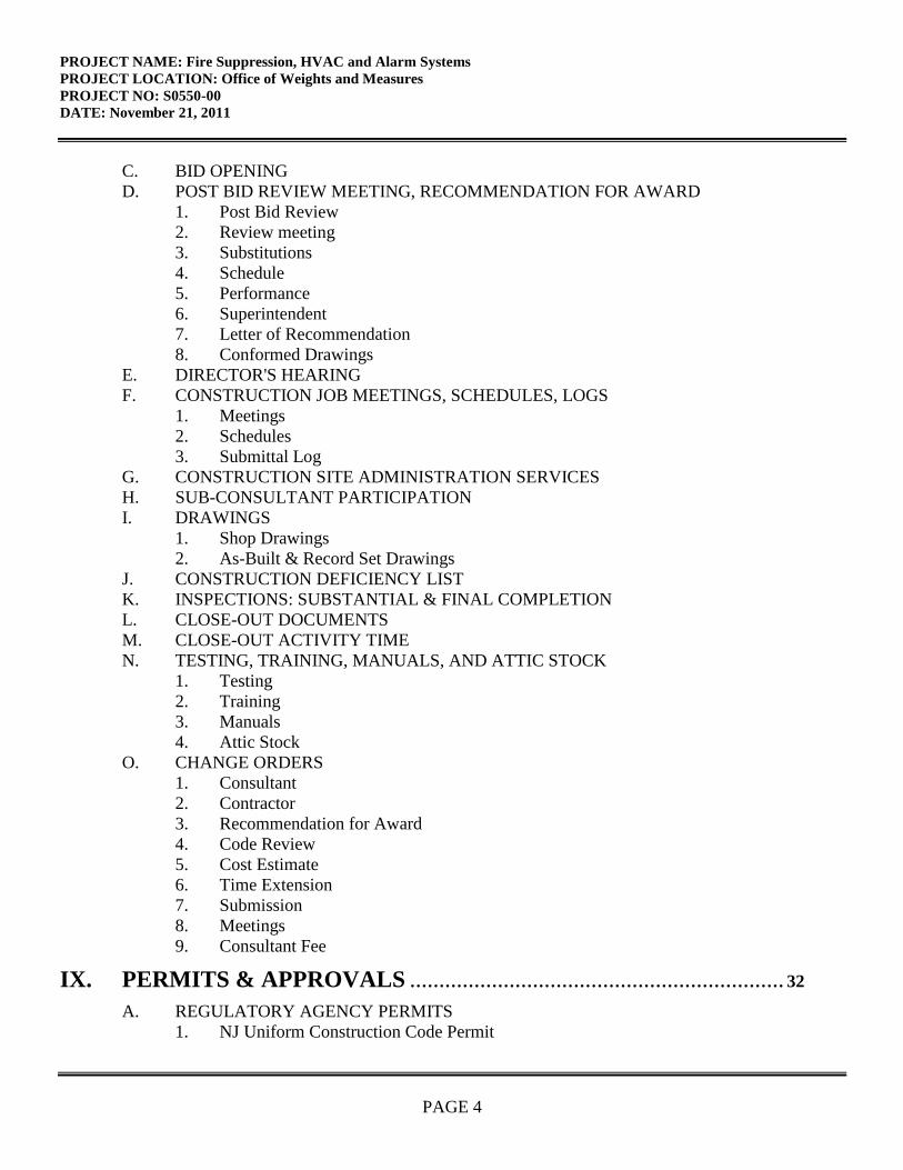
C. BID OPENING
D. POST BID REVIEW MEETING, RECOMMENDATION FOR AWARD
1. Post Bid Review
2. Review meeting
3. Substitutions
4. Schedule
5. Performance
6. Superintendent
7. Letter of Recommendation
8. Conformed Drawings
E. DIRECTOR'S HEARING
F. CONSTRUCTION JOB MEETINGS, SCHEDULES, LOGS
1. Meetings
2. Schedules
3. Submittal Log
G. CONSTRUCTION SITE ADMINISTRATION SERVICES
H. SUB-CONSULTANT PARTICIPATION
I. DRAWINGS
1. Shop Drawings
2. As-Built & Record Set Drawings
J. CONSTRUCTION DEFICIENCY LIST
K. INSPECTIONS: SUBSTANTIAL & FINAL COMPLETION
L. CLOSE-OUT DOCUMENTS
M. CLOSE-OUT ACTIVITY TIME
N. TESTING, TRAINING, MANUALS, AND ATTIC STOCK
1. Testing
2. Training
3. Manuals
4. Attic Stock
O. CHANGE ORDERS
1. Consultant
2. Contractor
3. Recommendation for Award
4. Code Review
5. Cost Estimate
6. Time Extension
7. Submission
8. Meetings
9. Consultant Fee
IX. PERMITS & APPROVALS ................................................................ 32
A. REGULATORY AGENCY PERMITS
1. NJ Uniform Construction Code Permit
PROJECT NAME: Fire Suppression, HVAC and Alarm Systems
PROJECT LOCATION: Office of Weights and Measures
PROJECT NO: S0550-00
DATE: November 21, 2011
PAGE 5
2. Other Regulatory Agency Approvals & Permits
3. Prior Approval Certification Letters
B. BARRIER FREE REQUIREMENTS
C. STATE INSURANCE APPROVAL
D. PUBLIC EMPLOYEES OCCUPATIONAL SAFETY & HEALTH PROGRAM
E. MULTI-BUILDING OR MULTI-SITE PERMITS
F. PERMIT MEETINGS
G. MANDATORY NOTIFICATIONS
H. CONSTRUCTION TRAILER PERMITS
I. SPECIAL INSPECTIONS
X. GENERAL REQUIREMENTS .......................................................... 35
A. SCOPE CHANGES
B. ERRORS & OMISSIONS
C. ENERGY INCENTIVE PROGRAM
D. AIR POLLUTION FROM ARCHITECTURAL COATINGS
XI. ALLOWANCES ................................................................................... 36
A. PERMIT ALLOWANCE
1. Permits
2. Permit Costs
3. Applications
4. Consultant Fee
B. HVAC SYSTEM DESIGN ALLOWANCE
XII. SUBMITTAL REQUIREMENTS ...................................................... 38
A. CONTRACT DELIVERABLES
B. CATALOG CUTS
C. PROJECT DOCUMENT BOOKLET
D. DESIGN DOCUMENT CHANGES
E. SINGLE-PRIME CONTRACT
XIII. SOW SIGNATURE APPROVAL SHEET ........................................ 40
XIV. CONTRACT DELIVERABLES ......................................................... 41
PROJECT NAME: Fire Suppression, HVAC and Alarm Systems
PROJECT LOCATION: Office of Weights and Measures
PROJECT NO: S0550-00
DATE: November 21, 2011
PAGE 6
XV. EXHIBITS ............................................................................................. 47
A. SAMPLE PROJECT SCHEDULE FORMAT
B. WEIGHTS AND MEASURES BUILDING LOCATION
C. OFFICE OF WEIGHTS AND MEASURES
D. JACOBS ARCHTECTS/ENGINEERS, INC. FIRE ALARM AND FIRE PROTECTION
STUDY
PROJECT NAME: Fire Suppression, HVAC and Alarm Systems
PROJECT LOCATION: Office of Weights and Measures
PROJECT NO: S0550-00
DATE: November 21, 2011
PAGE 7
I. OBJECTIVE
The objective of this project is to replace the existing fire alarm system and install a clean agent fire
suppression system in the small balance room at the Weights and Measures Building. Based on
available funding, an existing HVAC system in the Small Balance Room may be replaced.
II. CONSULTANT QUALIFICATIONS
A. CONSULTANT & SUB-CONSULTANT PRE-QUALIFICATIONS
The Consultant shall be a firm pre-qualified with the Division of Property Management &
Construction (DPMC) in the P010 Fire Protection Engineering Professional Discipline and have in-
house capabilities or Sub-Consultants pre-qualified with DPMC in P003 HVAC Engineering and all
other Architectural, Engineering and Specialty Disciplines necessary to complete the project as
described in this Scope of Work (SOW).
III. PROJECT BUDGET
A. CONSTRUCTION COST ESTIMATE (CCE)
The initial Construction Cost Estimate (CCE) for this project is $190,000.
The Consultant shall review this Scope of Work and provide a narrative evaluation and analysis of the
accuracy of the proposed project CCE in their technical proposal based on their professional
experience and opinion.
B. CURRENT WORKING ESTIMATE (CWE)
The Current Working Estimate (CWE) for this project is $280,300.
The CWE includes the construction cost estimate and all consulting, permitting and administrative
fees.
PROJECT NAME: Fire Suppression, HVAC and Alarm Systems
PROJECT LOCATION: Office of Weights and Measures
PROJECT NO: S0550-00
DATE: November 21, 2011
PAGE 8
The CWE is the Client Agency’s financial budget based on this project Scope of Work and shall not
be exceeded during the design and construction phases of the project unless DPMC approves the
change in Scope of Work through a Contract amendment.
C. COST ESTIMATING
On projects with a CCE under $750,000, the estimate may be prepared by the Consultant’s in-house
staff or their Sub-Consultant’s staff during each design phase of the project. However, if the CCE is
$750,000 or larger, the Consultant or Sub-Consultant providing the estimate must be pre-qualified
with DPMC in the P025 Estimating/Cost Analysis Specialty Discipline.
All cost estimates shall be adjusted for regional location, site factors, construction phasing, premium
time, building use group, location of work within the building, temporary swing space, security issues,
and inflation factors based on the year in which the work is to be performed.
All cost estimates must be submitted on a DPMC-38 Project Cost Analysis form at each design phase
of the project with a detailed construction cost analysis in CSI format (2004 Edition) for all
appropriate divisions and sub-divisions. The Project Manager will provide cost figures for those items
which may be in addition to the CCE such as art inclusion, CM services, etc. and must be included as
part of the CWE. This cost analysis must be submitted for all projects regardless of the Construction
Cost Estimate amount.
D. CONSULTANT’S FEES
The construction cost estimate for this project shall not be used as a basis for the Consultant’s design
and construction administration fees. The Consultant’s fees shall be based on the information
contained in this Scope of Work document and the observations made and/or the additional
information received during the pre-proposal meeting.
PROJECT NAME: Fire Suppression, HVAC and Alarm Systems
PROJECT LOCATION: Office of Weights and Measures
PROJECT NO: S0550-00
DATE: November 21, 2011
PAGE 9
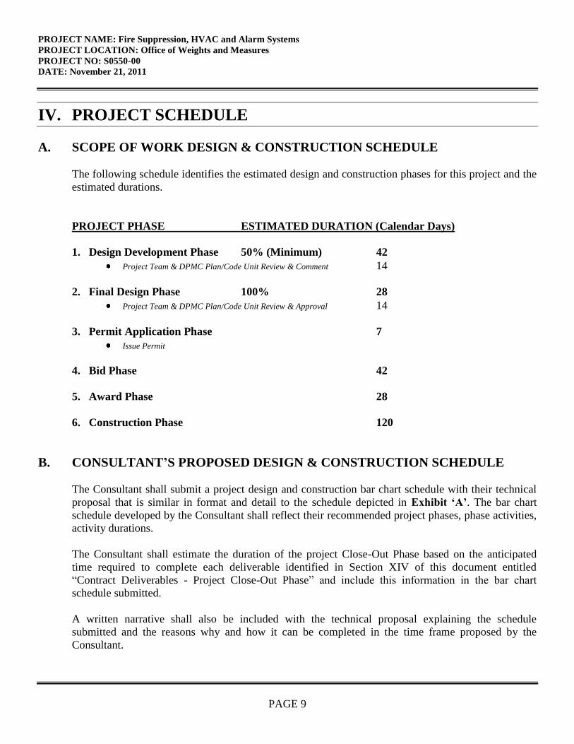
IV. PROJECT SCHEDULE
A. SCOPE OF WORK DESIGN & CONSTRUCTION SCHEDULE
The following schedule identifies the estimated design and construction phases for this project and the
estimated durations.
PROJECT PHASE ESTIMATED DURATION (Calendar Days)
1. Design Development Phase 50% (Minimum) 42
Project Team & DPMC Plan/Code Unit Review & Comment 14
2. Final Design Phase 100% 28
Project Team & DPMC Plan/Code Unit Review & Approval 14
3. Permit Application Phase 7
Issue Permit
4. Bid Phase 42
5. Award Phase 28
6. Construction Phase 120
B. CONSULTANT’S PROPOSED DESIGN & CONSTRUCTION SCHEDULE
The Consultant shall submit a project design and construction bar chart schedule with their technical
proposal that is similar in format and detail to the schedule depicted in Exhibit ‘A’. The bar chart
schedule developed by the Consultant shall reflect their recommended project phases, phase activities,
activity durations.
The Consultant shall estimate the duration of the project Close-Out Phase based on the anticipated
time required to complete each deliverable identified in Section XIV of this document entitled
“Contract Deliverables - Project Close-Out Phase” and include this information in the bar chart
schedule submitted.
A written narrative shall also be included with the technical proposal explaining the schedule
submitted and the reasons why and how it can be completed in the time frame proposed by the
Consultant.
PROJECT NAME: Fire Suppression, HVAC and Alarm Systems
PROJECT LOCATION: Office of Weights and Measures
PROJECT NO: S0550-00
DATE: November 21, 2011
PAGE 10
This schedule and narrative will be reviewed by the Consultant Selection Committee as part of the
evaluation process and will be assigned a score commensurate with clarity and comprehensiveness of
the submission.
C. CONSULTANT DESIGN SCHEDULE
The Project Manager will issue the Consultant’s approved project schedule at the first design kickoff
meeting. This schedule will be binding for the Consultant’s activities and will include the start and
completion dates for each design activity. The Consultant and Project Team members shall use this
schedule to ensure that all design milestone dates are being met for the project. The Consultant shall
update the schedule to reflect performance periodically (minimally at each design phase) for the
Project Team review and approval. Any recommendations for deviations from the approved design
schedule must be explained in detail as to the causes for the deviation(s) and impact to the schedule.
D. BID DOCUMENT CONSTRUCTION SCHEDULE
The Consultant shall include a construction schedule in Division 1 of the specification bid document.
This schedule shall contain, at minimum, the major activities and their durations for each trade
specified for the project. This schedule shall be in “bar chart” format and will be used by the
Contractors as an aid in determining their bid price. It shall reflect special sequencing or phased
construction requirements including, but not limited to: special hours for building access, weather
restrictions, imposed constraints caused by Client Agency program schedules, security needs, lead
times for materials and equipment, anticipated delivery dates for critical items, utility interruption and
shut-down constraints, and concurrent construction activities of other projects at the site and any other
item identified by the Consultant during the design phases of the project.
E. CONTRACTOR CONSTRUCTION PROGRESS SCHEDULE
The Contractor shall be responsible for preparing a coordinated combined progress schedule with the
Sub-Contractors after the award of the contract. This schedule shall meet all of the requirements
identified in the Consultant’s construction schedule. The construction schedule shall be completed in
accordance with the latest edition of the Instructions to Bidders and General Conditions entitled,
“Article 9, Construction Progress Schedule” (No CPM).
The Consultant must review and analyze this progress schedule and recommend approval/disapproval
to the Project Team until a satisfactory version is approved by the Project Team. The Project Team
must approve the baseline schedule prior to the start of construction and prior to the Contractor
submitting invoices for payment.
The Consultant shall note in Division 1 of the specification that the State will not accept the progress
schedule until it meets the project contract requirements and any delays to the start of the construction
work will be against the Contractor until the date of acceptance by the State.
PROJECT NAME: Fire Suppression, HVAC and Alarm Systems
PROJECT LOCATION: Office of Weights and Measures
PROJECT NO: S0550-00
DATE: November 21, 2011
PAGE 11
The construction progress schedule shall be reviewed, approved, and updated by the Contractor of
schedule, Consultant, and Project Team members at each regularly scheduled construction job meeting
and the Consultant shall note the date and trade(s) responsible for project delays (as applicable).
V. PROJECT SITE LOCATION & TEAM MEMBERS
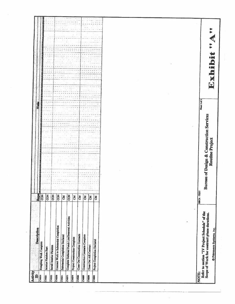
A. PROJECT SITE ADDRESS
The location of the project site is:
Office of Weights and Measures
1261 Routes 1 and 9 South
Avenel, NJ 07001
See Exhibit ‘B’ for the project site map.
B. PROJECT TEAM MEMBER DIRECTORY
The following are the names, addresses, and phone numbers of the Project Team members.
1. DPMC Representative:
Name: Nurul Hasan, Project Manager
Address: Division Property Management & Construction
10.3.4 Minutes Format: Prepare Job Meeting Minutes in approved format, figure 10.3.4-a
PROJECT NAME: Fire Suppression, HVAC and Alarm Systems
PROJECT LOCATION: Office of Weights and Measures
PROJECT NO: S0550-00
DATE: November 21, 2011
PAGE 45
10.4 Correspondence
10.5 Prepare and Deliver Conformed Drawings
10.7 Approve Contractors Invoicing and Payment Process
10.8 Approve Contractors 12/13 Form for Subs, Samples and Materials
10.10 Approve Test Reports
10.11 Approve Shop Drawings
10.12 Construction Progress Schedule
10.12.1 Construction Progress Schedule
10.13 Review & Recommend or Reject Change Orders
10.13.1 Scope Changes
10.13.2 Construction Change Orders
10.13.3 Field Changes
10.14 Construction Photographs
10.15 Submit Field Observation Reports
10.16 Submission Forms
Figure 10.3.4-a Job Meeting Format of Minutes
Figure 10.3.4-b Field Report
Figure 10.6 DPMC Insurance Form-24
Figure 10.6-a Unit Schedule Breakdown
Figure 10.6-b Monthly Estimate for Payment to Contractor DPMC 11-2
Figure 10.6-c Monthly Estimate for Payment to Contractor DPMC 11-2A
Figure 10.6-d Invoice DPMC 11
Figure 10.6-e Prime Contractor Summary of Stored Materials DPMC 11-3
Figure 10.6-f Agreement & Bill of Sale certificate for Stored Materials DPMC 3A
Figure 10.7-a Approval Form for Subs, Samples & Materials DPMC 12
Figure 10.7-b Request for Change Order DPMC 9b
Figure 10.9 Transmittal Form DPMC 13
Figure 10.10 Submission Checklist
PROJECT NAME: Fire Suppression, HVAC and Alarm Systems
PROJECT LOCATION: Office of Weights and Measures
PROJECT NO: S0550-00
DATE: November 21, 2011
PAGE 46
PROJECT CLOSE-OUT PHASE
11.1 Responsibilities: Plan, Schedule and Execute Close-Out Activities
11.2 Commencement: Initiate Close-Out w/DPMC 20A Project Close-Out Form
11.3 Develop Punch List & Inspection Reports
11.4 Verify Correction of Punch List Items
11.5 Determination of Substantial Completion
11.6 Ensure Issuance of “Temporary Certificate of Occupancy or Approval”
11.7 Initiation of Final Contract Acceptance Process
11.8 Submission of Close-Out Documentation
11.8.1 As-Built & Record Set Drawings, 3 sets AUTOCAD Discs Delivered to DPMC
11.8.2 (a) Maintenance and Operating manuals, Warranties, etc.: 7 sets each
(b) Guarantees
(c) Testing and Balancing Reports
(d) Shop Drawings
(e) Letter of Contract Performance
11.8.3 Final Cost Analysis-Insurance Transfer DPMC 25
11.8.4 This Submission Checklist
11.9 Final Payment
11.9.1 Contractors Final Payment
11.9.2 A/E Invoice and Close-Out Forms for Final Payment
11.10 Final Performance Evaluation of the A/E and the Contractors
11.11 Ensure Issuance of a “Certificate of Occupancy or Approval”
11.12 Submission Forms
Figure 11.2 Project Close-Out Documentation List DPMC 20A
Figure 11.3-a Certificate of Substantial Completion DPMC 20D
Figure 11.3-b Final Acceptance of Consultant Contract DPMC 20C
Figure 11.5 Request for Contract Transition Close-Out DPMC 20X
Figure 11.7 Final Contract Acceptance Form DPMC 20
PROJECT NAME: Fire Suppression, HVAC and Alarm Systems
PROJECT LOCATION: Office of Weights and Measures
PROJECT NO: S0550-00
DATE: November 21, 2011
PAGE 47
Figure 11.8.3-a Final Cost Analysis
Figure 11.8.3-b Insurance Transfer Form DPMC 25
Figure 11.8.4 Submission Checklist
XV. EXHIBITS
The attached exhibits in this section will include a sample project schedule, and any supporting
documentation to assist the Consultant in the design of the project such as maps, drawings,
photographs, floor plans, studies, reports, etc.
END OF SCOPE OF WORK
February 7, 1997Rev.: January 29, 2002
Responsible Group Code Table
The codes below are used in the schedule field “GRP” that identifies the group responsible for theactivity. The table consists of groups in the Division of Property Management & Construction(DPMC), as well as groups outside of the DPMC that have responsibility for specific activities ona project that could delay the project if not completed in the time specified. For reportingpurposes, the groups within the DPMC have been defined to the supervisory level ofmanagement (i.e., third level of management, the level below the Associate Director) to identifythe “functional group” responsible for the activity.
CODE DESCRIPTION REPORTS TO ASSOCIATE DIRECTOR OF:
CM Contract Management Group Contract Management
CA Client Agency N/A
CSP Consultant Selection and Technical ServicesPrequalification Group
AlE Architect/Engineer N/A
PR Plan Review Group Technical Services
CP Construction Procurement Planning & Administration
CON Construction Contractor N/A
FM Financial Management Group Planning & Administration
OEU Office of Energy and N/AUtility Management
PD Project Development Group Planning & Administration
EXHIBIT ‘A’
Act
ivity
lW
kID
Des
crip
tion
j9
mn
11
rnH
i..
.flH
Iiii
iI3H
Hii3
I
II
I
II
I
IL
’!
IC
V3t
Sche
dule
/Con
duct
Pred
esig
n/Pr
ojec
t Kic
kO
ffM
tgC
MI
II
.II;’
l:IiII_I:
IC
V30
50Pr
epar
ePro
gram
Phas
eSu
bmitt
alP
iECV
302l
Dis
trib
ute
Prog
ram
Subm
ittal
for R
evie
wC
MI
—.1
H.
•.
H:.L
’.11
HCV
3O7
Pre
pare
&S
ub
mit
Pre
ct
Cost
Anal
ysi
s(D
PM
C38)
CM
ICV
3022
Rev
iew
&A
ppro
ve
Prog
ram
Subm
itta
lC
A
L1
CV30
23R
evie
w&
App
rove
Prog
ram
Subm
itta
lP
RI1
1—
—CY
3024
Rev
iew
&A
ppro
ve
Pro
gra
mS
ubm
itta
lC
MI
1CV
3025
Con
soli
date
&R
eturn
Prog
ram
Subm
itta
lC
omm
ents
CM
IV
CV3V
IOP
repa
reSc
hem
atic
Pha
seS
ubm
itta
lPi
EI
I—
IIi
i‘I
CV30
3iD
istr
ibute
Sche
mat
icSu
bmitt
alfo
rR
evie
wC
MI
I——
--
—-
-
——
—-
——
-L
——
-—
CVSQ
S7Pr
epar
e&
Subm
itP
roje
ctC
ost A
nal
ysi
s(D
PMC
38)
CM
I
III
II
iII
I:13131
IuII’H
HCV
3OSZ
Rev
iew
&A
ppro
veS
chem
atic
Subin
itts
lC
AH
iH
’H
’‘‘
‘H
•‘
Hi
‘CV
3033
Rev
iew
&A
ppro
ve
Sch
emat
icS
ubm
itta
lP
RI
:CV
3034
Rev
iew
&A
ppro
ve
Sche
mat
icSu
bmitt
alC
M1
V4I_3
.IV
,,V
I,,V
VV
3O
Con
soli
date
&R
etur
nScl
icm
atic
Sub
mit
talo
mm
ent
CM
:ilII3,,..4
.1
43•
II
11111
43
IIV
,’Il
1.11:
II
43
3.1151.
44
‘till
3H
1411,,l_.i
‘‘H
——
—
1”
I‘
‘I
——
—“
‘
CVSO
4OP
iepa
reD
esig
nD
evel
opm
ent
Pha
seS
ubnu
ltal
AE
.I
4.
V3
Vj
—II
III
111’
4:
II.
•:
4.1
II
I.1.
31
III3.
I3
;1
Ii
CV
3O1
Dis
trib
uteD
DSu
bmitt
alfo
r Rev
iew
CM
3(V
iO47
Pre
par
e&
Su
bm
itP
roje
ctC
ost
Ana
lysi
s(D
PM
C3
8)
CM
31
33
CV30
42R
evie
w&
Appro
ve
Des
ign
Dev
elopm
ent
Su
bm
itta
lC
A1
11
3
3C
’30
3R
evie
w&
Appro
ve
Des
ign
Dev
elopm
ent
Su
bm
itta
lP
RI
CV
3044
Rev
iew
&A
ppro
ve
Des
ign
Dev
elopm
ent
Sub
mit
tal
CM
1
3
3
3CV
SO4S
Con
soli
date
&R
etur
nI)
DS
ubm
itta
lC
om
men
tsC
MI
33
CV3O
SOP
rep
are
Fin
alD
esig
nP
hase
Subm
itta
lI
33
31
CV
3OSI
Dis
trib
ute
Fina
lDesig
nSu
bmitt
alfo
r Rev
iew
CM
I3
IC
’b’
Rev
iew
&Ap
prov
eF
inal
Des
ign
Subm
ittal
CA
43
Rev
iew
&A
ppro
ve
Fin
alD
esig
nS
ubm
itta
lP
RI
CV
3054
Rev
iew
Fin
alD
esig
nS
ubm
itl
forC
onst
ruct
abil
ity
OC
S—
NO
TE
:.
DT
Tsh
eet t
or3
——
Ref
erto
sect
ion
“IV
Pro
ject
Sch
edul
e”of
the
Bur
eau
ofD
esig
n&
Con
stru
ctio
nS
ervi
ces
Scop
eof
Wor
kfo
rco
ntra
ctph
ase
dura
tions
.R
outi
neP
roje
ctE
xli
i bit
0P
rtm
avor
aS
yste
ms,
Inc.
-U
3
q)
03
o-
C0
,0CC
p.
CC
—s
--
{-
L--I-
---——--L---—
:::1:::1::.::::.:.::z:::::.::::L—
9 .........
F.;-.+.
1----1-------
L .i...4...
.—...4.1..-
I-----I----
I
0
3
C’,‘9
30,
I00
I I
0
000On00zz.
0,
?.1
—---.-.--r--—
-.:
.-
--.-.t.——-----
-.
-ZEt---
::z:.
•.t.:
-.)-----
.3.—.--——--
-1”-----
:-•-----.
:_:.L:_-
::_f----
-—
--•--..-
—H----——----
-1---------
--——-
-—.t-—-. —-
.I--
i.--.——-—-.-——— .—
-—------------.——.--------------
—-—.-.-—
-I-—----
-f-----b-.- -—-———.—--—————.—————
—I
.4
-.
-:-T-:.-
r—
- r&.
__A
4%:
______
Ia
Wei
ghts
and
Mea
sure
s
4\c
AJ
XX
aJS
Pts
__
4I3A
:fP
at
__--a
_
)2C
iP
rrac
yL
egal
Adv
erti
se.
s.
Wei
ghts
and
Mea
sure
sB
uild
ing
Loc
atio
nE
XH
IBIT
‘B’
Off
ice
ofW
eigh
tsan
dM
easu
res
EX
HIB
IT‘C
’
ITR
icK
W°
-.-
‘O
fFIC
ES
LM
3’m
Presented to:The State of New Jersey
Department of Law and Public SafetyOffice of the Attorney General
for the:
Weights and Measures BuildingFire Alarm and Fire ProtectionSystems Study1261 Route 1&9 South, Avenel, NJ 07001
In i?e/erence to:Project Number X0150-00, Work Order 2
March 30, 2011
Suhmiited th;:
Jacobs Architects/Engineers. Inc.299 Madison AvenueMorristown, NJ 07962(973) 267-0555
EXHIBIT ‘D’
JACOBS
Weights and Measures Building March 30, 2011Avenel, NJFire Alarm and Fire Protection Systems Study
TABLE OF CONTENTS
Section Page
1.0 Introduction 12.0 Existing Systems and Conditions 23.0 System Deficiencies 74.0 Recommendations 85.0 Opinion of Probable Cost 106.0 Summary 11
AppendixOpinion of Probable Construction Cost Detail A-IPhotos B-IExisting Fire Alarm System Components
JACOBS
Weights and Measures Building March 30, 2011Avenel, NJFire Alarm and Fire Protection Systems Study
1.0 Introduction
As requested by the State of New Jersey Department of Law and Public Safety and the Office ofthe Attorney General, Jacobs Architects/Engineers, Inc. (Jacobs) prepared this Fire Alarm andFire Protection Study which includes evaluation of three primary components:
1. Upgrade/Replacement of the existing fire alarm system2. Installation of a clean agent (e.g. FM-200) fire suppression system in the Small Scales
Room3. Extension of the existing limited are sprinkler system
The Weights and Measures Building, located at 1261 Route l&9 South in Avenel, New Jerseyand constructed approximately 1987, is a single-story structure, approximately 16,000 totalsquare feet and consists of an Office Area, Lab Wing and Truck Wing. The existing fire alarmsystem is in need of repair and does not meet current standards for fire alarm systems. TheSmall Scales Room houses the majority of the sensitive scales and equipment, which the statewould like to protect with a clean agent fire suppression system (e.g. FM-200). Currently, onlylimited areas of the building are protected with a wet-pipe fire protection system. There is alsoan automatic standpipe system located in the building.
On February 10, 2011 Jacobs performed a site visit including a general walk-through of thebuilding and review of the existing fire alarm system and limited area fire protection system.
This study includes a description of the existing fire alarm and fire protection systems, codeanalysis, and description of identified system deficiencies, recommendations for upgrade, andopinion of probable construction cost estimate.
Photos taken during the site visit and additional detail for the opinion of probable cost estimateare included in the Appendix of this report.
JACOBS1
Weights and Measures Building March 30, 2011Avenel, NJFire Alarm and Fire Protection Systems Study
2.0 Existing Systems and Conditions
Code AnalysisA. Use and Occupancy (IBC Chapters 3, 4 and 5):
a. Per the original construction drawings (circa 1987), the building is classified as BOCABusiness Group B for the Office Wing (4,647 SF) and Lab Wng (4,722 SF) and StorageGroup S-i for the Truck Wing (6,639 SF). These classifications are consistent with the2009 International Building Code (IBC), currently adopted by the State of New Jersey.
b. Per IBC section 311.2, Moderate-hazard storage, Group S-I includes motor vehiclerepair garages complying with the maximum allowable quantities of hazardous materialsincluding combustible liquids and flammable liquids. This includes, but is not limited tothe following maximum quantities:
i. Diesel fuel (Cass 2 combustible liquid) — maximum 120 gallonsii. Gasoline (Class lB flammable liquid) — maximum 120 gallons
iii. Motor Oil (Class 3B combustible liquid) — maximum 13,200 gallonsiv. Note: the maximum quantities for diesel fuel and gasoline can be increased by
100% in a building equipped with an automatic sprinkler system.c. Per IBC section 406.6, Repair Garages:
i. Shall not be used for fuel dispensingii. Mixed Uses are as allowed per IBC section 508.1
iii. Shall be ventilated per the International Mechanical Code (IMC)iv. Floor shall be concrete or similar non-combustible material.v. Heating equipment shall be installed per the IMC.
vi. Repair garages used for repair of vehicles fueled by non-odorized gases such ashydrogen or non-odorized LPG shall be provided with an approved flammablegas-detection system.
d. Mixed-Use and Occupancyi. Incidental Uses: Per IBC section 508.2, the following areas require a 1-hour fire
separation or automatic fire-extinguishing system1. Furnace Rooms with any piece of equipment over 400,000 Btu/hr2. Boiler Rooms where the largest piece of equipment is over 15 psi and 10
horsepower3. Storage Rooms over 100 square feet
ii. Accessory Occupancies: Per IBC section 508.3.1 states that a separate UseClassification can be considered as an accessory occupancy if less than 10% ofthe total area of the building.
1. Note: since the truck wing is over 10% of the total building area, it cannotbe considered an accessory occupancy.
iii. Separated Occupancies: Per IBC 508.3.3 and Table 503.3.3, there is noseparation required between Occupancy Types B and SI.
B. Construction Classification (IBC Chapter 6):a. Per the original drawings, the BOCA construction classification is 2C, which is the
equivalent of the IBC Type II B construction classification.b. General Building Height and Area Limitations (IBC section 503):
i. Per Table 503 for Type II BI. For Group B — maximum 3 stories or 55 feet high and 23,000 SF per story2. For Group S-i — maximum 2 stories or 55 feet high and 17,500 SF per
story
JACOBS2
Weights and Measures Building March 30, 2011Avenel. NJFire Alarm and Fire Protection Systems Study
C. Automatic Sprinkler System (IBC Chapter 9):a. Per IBC section 903.2.9, Group S-i shall be provided with a automatic sprinkler system,
if:i. A Group 5-1 exceeds 12,000 SF
ii. Is located more than 3-stories above gradeiii. The combined area of all S-I fire areas on all floors exceeds 24,000 SFiv. Used for storage of commercial trucks or buses where the fire area exceeds
5,000 SFb. Per IBC section 903.2.9.1, Repair Garages shall be provided with a automatic sprinkler
system, if::i. Buildings having 2 or more stories above grade containing a repair garage with a
fire area exceeding 10,000 SFii. One-story buildings with a fire area containing a repair garage exceeding 12,000
SFiii. Buildings with a repair garage in the basementiv. Group 5-1 fire area used for repair of commercial trucks or buses where the fire
area exceeds 5,000 SFc. Per IBC section 903.2.13, an automatic sprinkler system is required if the Automatic
Sprinkler System Threshold is exceededi. For Group B, Construction Class II B, the threshold is 36,000 SF per floor
D. Standpipe Systems (IBC chapter 9):a. Are to be installed in accordance with NFPA 14
i. Pipe sizing requirements:I. Per IBC section 905.2.1, piping is to be sized to maintain a residual
pressure of 65 psi at the topmost outlet2. Per IBC section 905.2.1.1, risers are to be sized for a minimum flow of
500 GPM3. Per IBC section 905.2.1.2, the system piping is to be sized for a minimum
flow of 500 GPMb. Per IBC section 905.3.2, in buildings exceeding 10,000 SF in area per story, Class I
automatic wet or manual wet standpipes shall be provided where any portion of thebuilding’s interior area is more that 200 feet of travel vertically or horizontally from thenearest point of fire department access.
c. Per IBC section 905.4 Class I house connections shall be located:i. At each floor level, at every exit stairway, on each side of the wall adjacent to the
exit opening except where the floor areas adjacent to a horizontal exit arereachable from exit stairway outlets by a 30-foot hose stream from a nozzleattached to 100 feet of hose.
ii. At every exit passageway at the entrance from the exist passage to other areasof the building
iii. At the highest landing of a stairway with roof accessE. Fire Alarm and Detection System (IBC section 907)
a. Are to be installed in accordance with NFPA 72
JACOBS3
Weights and Measures Building March 30, 2011Avenel. NJFire Alarm and Fire Protection Systems Study
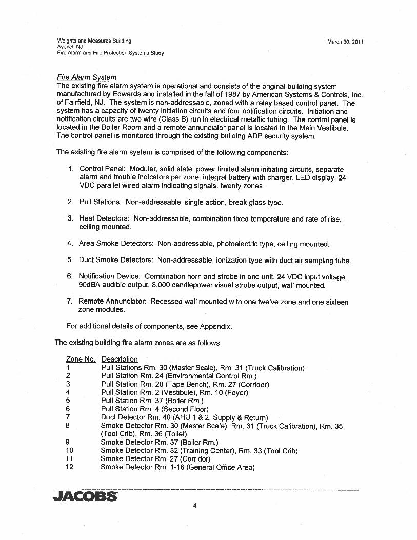
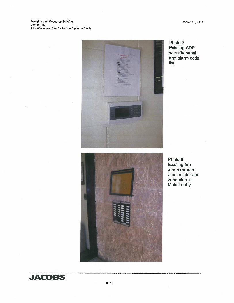
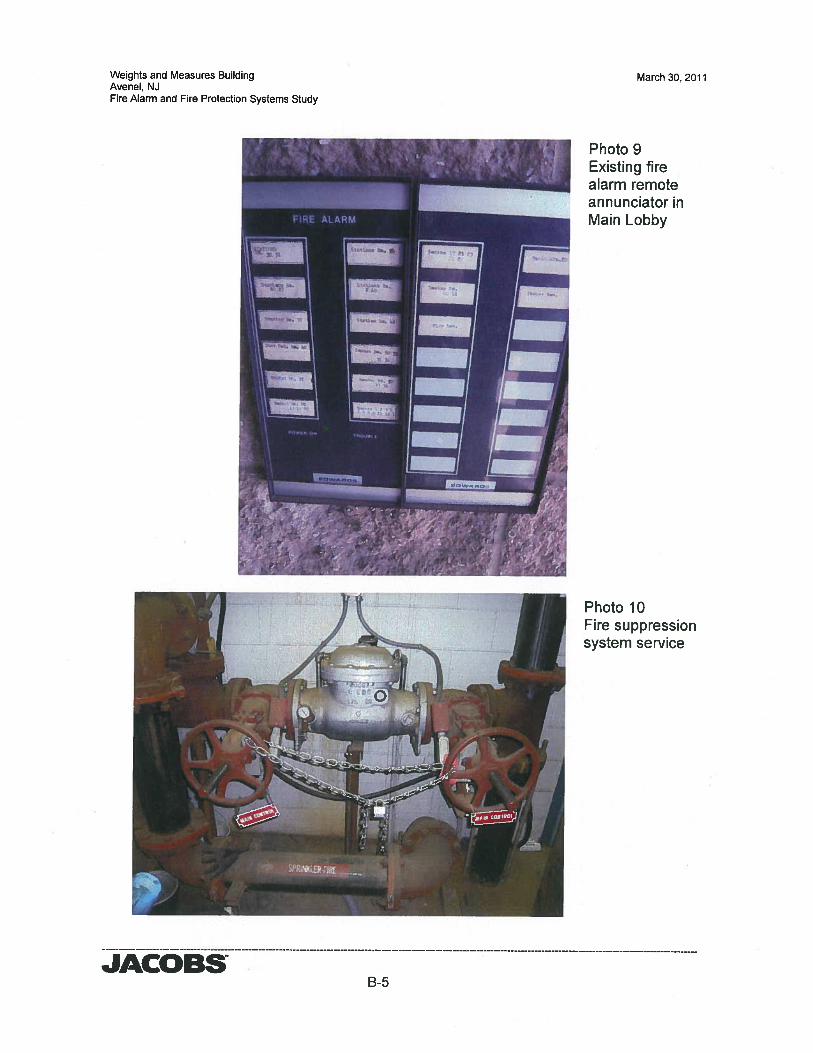
Fire Alarm SystemThe existing fire alarm system is operational and consists of the original building systemmanufactured by Edwards and installed in the fall of 1987 by American Systems & Controls, Inc.of Fairfield, NJ. The system is non-addressable, zoned with a relay based control panel. Thesystem has a capacity of twenty initiation circuits and four notification circuits. Initiation andnotification circuits are two wire (Class B) run in electrical metallic tubing. The control panel islocated in the Boiler Room and a remote annunciator panel is located in the Main Vestibule.The control panel is monitored through the existing building ADP security system.
The existing fire alarm system is comprised of the following components:
1. Control Panel: Modular, solid state, power limited alarm initiating circuits, separatealarm and trouble indicators per zone, integral battery with charger, LED display, 24VDC parallel wired alarm indicating signals, twenty zones.
2. Pull Stations: Non-addressable, single action, break glass type.
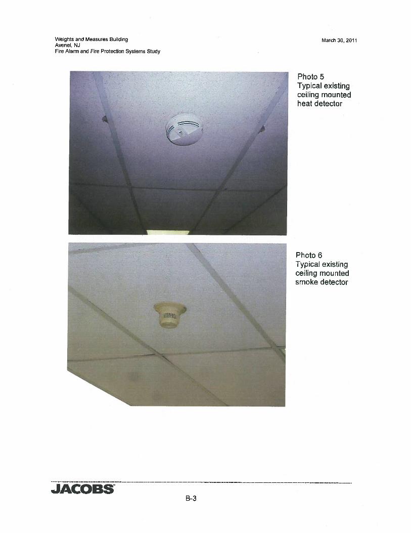
3. Heat Detectors: Non-addressable, combination fixed temperature and rate of rise,ceiling mounted.
4. Area Smoke Detectors: Non-addressable, photoelectric type, ceiling mounted.
5. Duct Smoke Detectors: Non-addressable, ionization type with duct air sampling tube.
6. Notification Device: Combination horn and strobe in one unit, 24 VDC input voltage,9OdBA audible output, 8,000 candlepower visual strobe output, wall mounted.
7. Remote Annunciator: Recessed wall mounted with one twelve zone and one sixteenzone modules.
For additional details of components, see Appendix.
The existing building fire alarm zones are as follows:
Zone No. DescriptionI Pull Stations Rm. 30 (Master Scale), Rm. 31 (Truck Calibration)2 Pull Station Rm. 24 (Environmental Control Rm.)3 Pull Station Rm. 20 (Tape Bench), Rm. 27 (Corridor)4 Pull Station Rm. 2 (Vestibule), Rm. 10 (Foyer)5 Pull Station Rm. 37 (Boiler Rm.)6 Pull Station Rm. 4 (Second Floor)7 Duct Detector Rm. 40 (AHU I & 2, Supply & Return)8 Smoke Detector Rm. 30 (Master Scale), Rm. 31 (Truck Calibration), Rm. 35
The existing fire alarm system operation is as follows:Initiation devices are grouped together as a circuit with each circuit on a zone. When any onedevice is activated on a zone, the notification appliances are activated, the zone is annunciatedon the control panel and remote annunciator, and a signal is transmitted to the building securitysystem monitored by ADP. There is an exterior weatherproof horn/strobe on the building nearthe main entrance.
JACOBS5
Weights and Measures Building March 30, 2011Avenel, NJFire Alarm and Fire Protection Systems Study
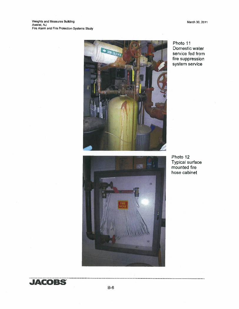
Fire Protection SystemsThe existing fire protection system includes a 6” fire service with main shut-off OS&Y valves,backflow preventer, separate water meter, siamese fire department connection, and drain andincludes a limited area sprinkler system and standpipe system.
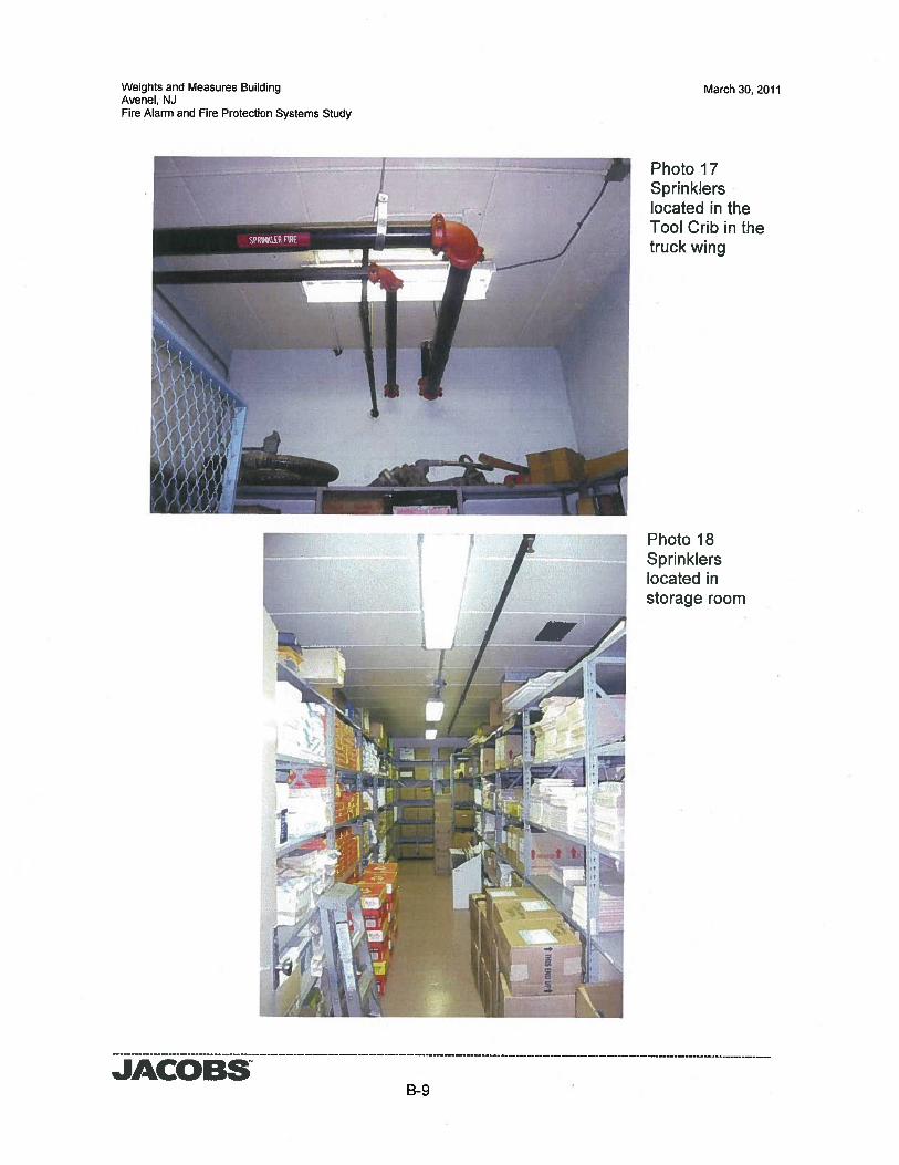
Sprinklers are installed in limited areas of the building including the following:• Boiler Room• Storage Rooms• Tools Crib in the Truck Calibration Area• Tank Calibration Area located on above the Truck Calibration Area and adjoining
Passage and Stairway• Mezzanine Level Mechanical Room
The sprinkler piping is primarily grooved piping with mechanical couplings (i.e. Victaulic piping)for piping 2” to 6” and screwed fittings for piping smaller than 2”. In addition to the limited areasprinkler system, the fire protection system includes an automatic wet standpipe system locatedthroughout the building with fire hose cabinets located within the main corridor and stairwayservicing the Mezzanine Level and Upper Level/Roof Access.
The standpipe riser serving the Stairway and Upper Level Passage is a combined standpipeand sprinkler riser serving fire hose cabinets and the sprinklers on the Upper Level.
A 1” inspectors test is located at the Upper Level Passage and at the Ground Floor landing ofthe Stairway.
JACOBS6
Weights and Measures Building March 30, 2011Avenel, NJFire Alarm and Fire Protection Systems Study
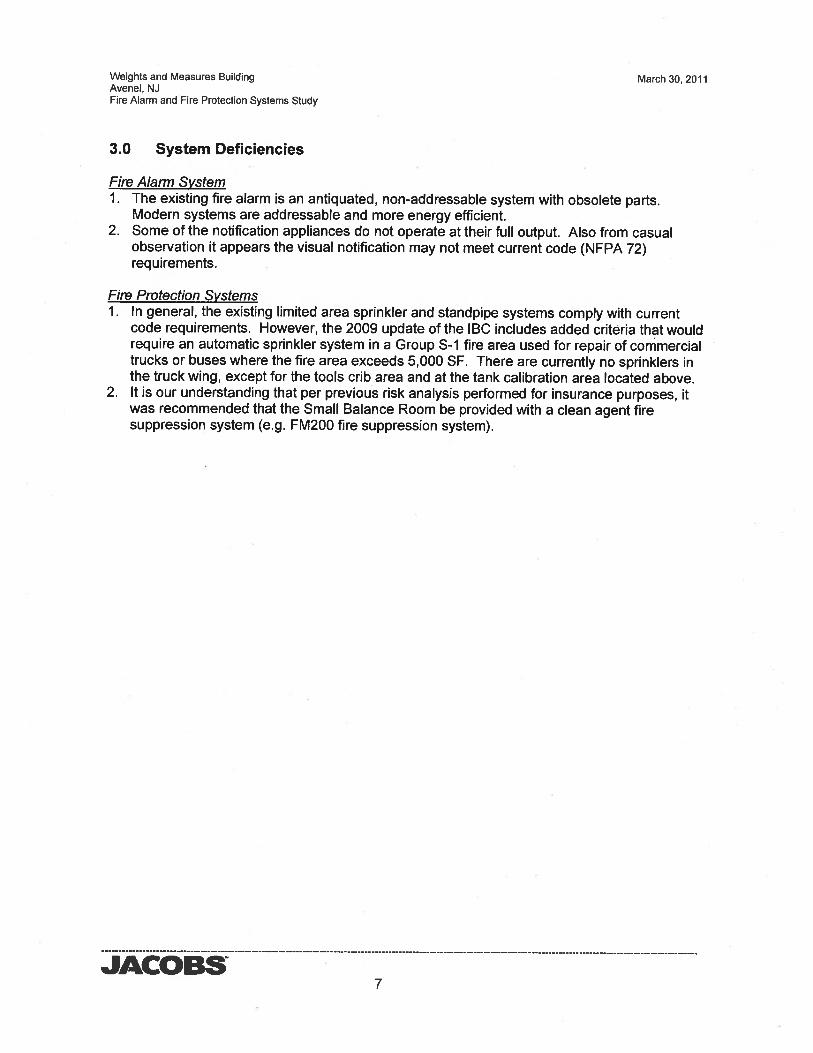
3.0 System Deficiencies
Fire Alarm System1. The existing fire alarm is an antiquated, non-addressable system with obsolete parts.
Modern systems are addressable and more energy efficient.2. Some of the notification appliances do not operate at their full output. Also from casual
observation it appears the visual notification may not meet current code (NFPA 72)requirements.
Fire Protection SystemsI. In general, the existing limited area sprinkler and standpipe systems comply with current
code requirements. However, the 2009 update of the BC includes added criteria that wouldrequire an automatic sprinkler system in a Group S-I fire area used for repair of commercialtrucks or buses where the fire area exceeds 5,000 SF. There are currently no sprinklers inthe truck wing, except for the tools crib area and at the tank calibration area located above.
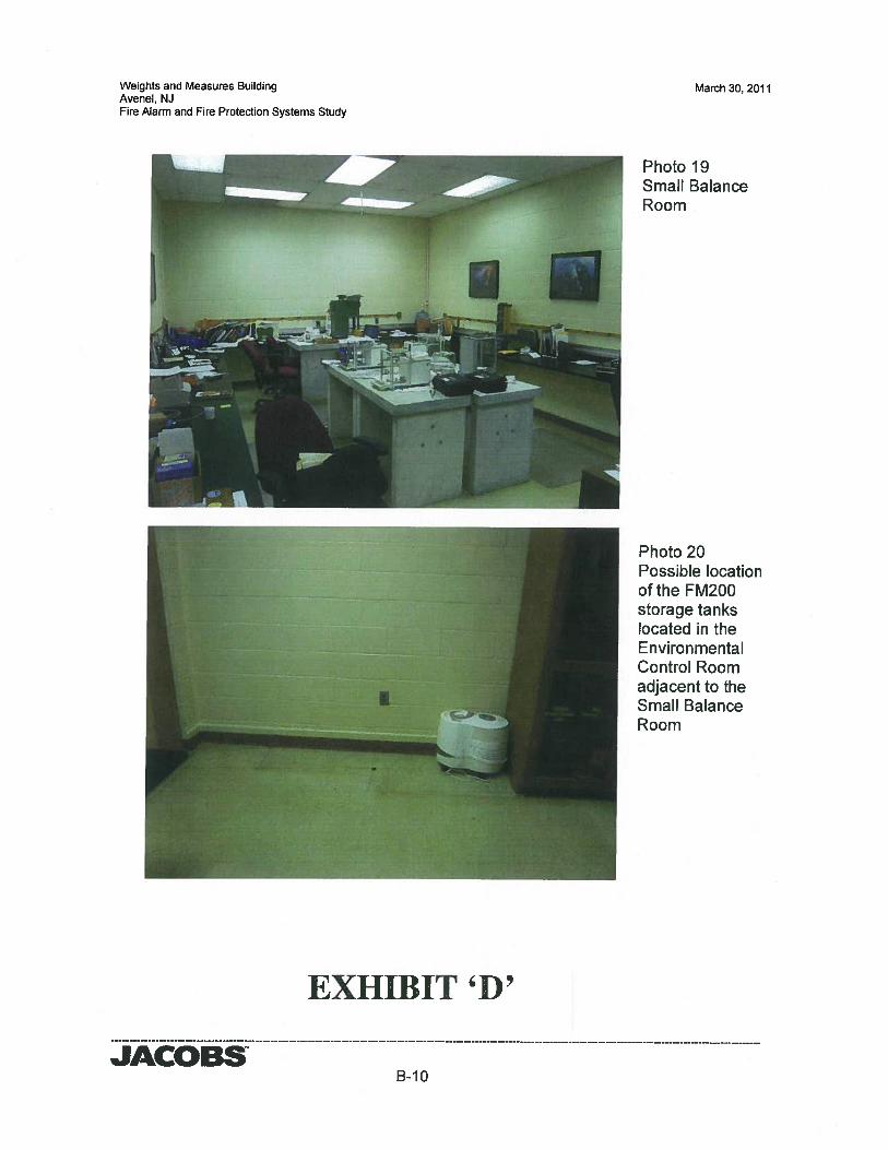
2. It is our understanding that per previous risk analysis performed for insurance purposes, itwas recommended that the Small Balance Room be provided with a clean agent firesuppression system (e.g. FM200 fire suppression system).
JACOBS7
Weights and Measures Building March 30, 2011Avenel, NJFire Alarm and Fire Protection Systems Study
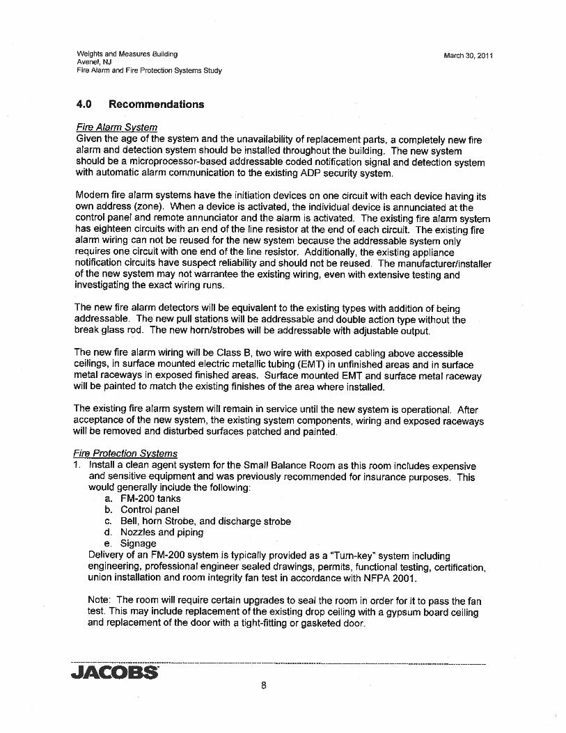
4.0 Recommendations
Fire Alarm SystemGiven the age of the system and the unavailability of replacement parts, a completely new firealarm and detection system should be installed throughout the building. The new systemshould be a microprocessor-based addressable coded notification signal and detection systemwith automatic alarm communication to the existing ADP security system.
Modern fire alarm systems have the initiation devices on one circuit with each device having itsown address (zone). When a device is activated, the individual device is annunciated at thecontrol panel and remote annunciator and the alarm is activated. The existing fire alarm systemhas eighteen circuits with an end of the line resistor at the end of each circuit. The existing firealarm wiring can not be reused for the new system because the addressable system onlyrequires one circuit with one end of the line resistor. Additionally, the existing appliancenotification circuits have suspect reliability and should not be reused. The manufacturerfinstallerof the new system may not warrantee the existing wiring, even with extensive testing andinvestigating the exact wiring runs.
The new fire alarm detectors will be equivalent to the existing types with addition of beingaddressable. The new pull stations will be addressable and double action type without thebreak glass rod. The new horn/strobes will be addressable with adjustable output.
The new fire alarm wiring will be Class B, two wire with exposed cabling above accessibleceilings, in surface mounted electric metallic tubing (EMT) in unfinished areas and in surfacemetal raceways in exposed finished areas. Surface mounted EMT and surface metal racewaywill be painted to match the existing finishes of the area where installed.
The existing fire alarm system will remain in service until the new system is operational. Afteracceptance of the new system, the existing system components, wiring and exposed racewayswill be removed and disturbed surfaces patched and painted.
Fire Protection Systems1. Install a clean agent system for the Small Balance Room as this room includes expensive
and sensitive equipment and was previously recommended for insurance purposes. Thiswould generally include the following:
a. FM-200 tanksb. Control panelc. Bell, horn Strobe, and discharge strobed. Nozzles and pipinge. Signage
Delivery of an FM-200 system is typically provided as a “Turn-key” system includingengineering, professional engineer sealed drawings, permits, functional testing, certification,union installation and room integrity fan test in accordance with NFPA 2001.
Note: The room will require certain upgrades to seal the room in order for it to pass the fantest. This may include replacement of the existing drop ceiling with a gypsum board ceilingand replacement of the door with a tight-fitting or gasketed door.
JACOBS8
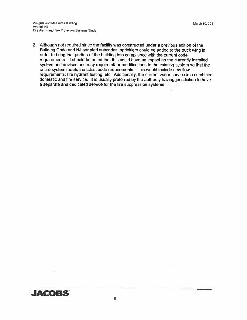
Weights and Measures Building March 30, 2011Avenel, NJFire Alarm and Fire Protection Systems Study
2. Although not required since the facility was constructed under a previous edition of theBuilding Code and NJ adopted subcodes, sprinklers could be added to the truck wing inorder to bring that portion of the building into compliance with the current coderequirements. It should be noted that this could have an impact on the currently installedsystem and devices and may require other modifications to the existing system so that theentire system meets the latest code requirements. This would include new flowrequirements, fire hydrant testing, etc. Additionally, the current water service is a combineddomestic and fire service, It is usually preferred by the authority having jurisdiction to havea separate and dedicated service for the fire suppression systems.
JACOBS9
Weights and Measures Building March 30, 2011Avenel, NJFire Alarm and Fire Protection Systems Study
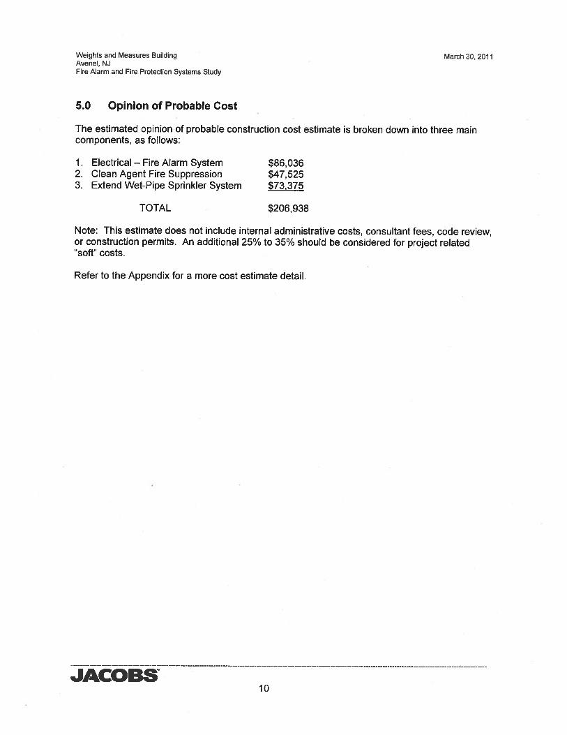
5.0 Opinion of Probable Cost
The estimated opinion of probable construction cost estimate is broken down into three maincomponents, as follows:
1. Electrical — Fire Alarm System $86,0362. Clean Agent Fire Suppression $47,5253. Extend Wet-Pipe Sprinkler System $73375
TOTAL $206,938
Note: This estimate does not include internal administrative costs, consultant fees, code review,or construction permits. An additional 25% to 35% should be considered for project related“soft” costs.
Refer to the Appendix for a more cost estimate detail.
JACOBS10
Weights and Measures Building March 30, 2011Avenel, NJFire Alarm and Fire Protection Systems Study
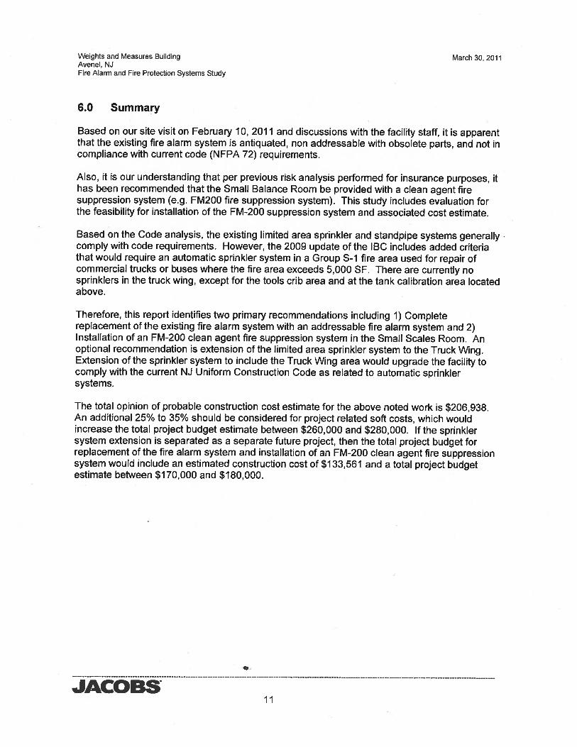
6.0 Summary
Based on our site visit on February 10, 2011 and discussions with the facility staff, it is apparentthat the existing fire alarm system is antiquated, non addressable with obsolete parts, and not incompliance with current code (NFPA 72) requirements.
Also, it is our understanding that per previous risk analysis performed for insurance purposes, ithas been recommended that the Small Balance Room be provided with a clean agent firesuppression system (e.g. FM200 fire suppression system). This study includes evaluation forthe feasibility for installation of the FM-200 suppression system and associated cost estimate.
Based on the Code analysis, the existing limited area sprinkler and standpipe systems generallycomply with code requirements. However, the 2009 update of the IBC includes added criteriathat would require an automatic sprinkler system in a Group S-i fire area used for repair ofcommercial trucks or buses where the fire area exceeds 5,000 SF. There are currently nosprinklers in the truck wing, except for the tools crib area and at the tank calibration area locatedabove.
Therefore, this report identifies two primary recommendations including 1) Completereplacement of the existing fire alarm system with an addressable fire alarm system and 2)Installation of an FM-200 clean agent fire suppression system in the Small Scales Room. Anoptional recommendation is extension of the limited area sprinkler system to the Truck Wing.Extension of the sprinkler system to include the Truck Wing area would upgrade the facility tocomply with the current NJ Uniform Construction Code as related to automatic sprinklersystems.
The total opinion of probable construction cost estimate for the above noted work is $206,938.An additional 25% to 35% should be considered for project related soft costs, which wouldincrease the total project budget estimate between $260,000 and $280,000. If the sprinklersystem extension is separated as a separate future project, then the total project budget forreplacement of the fire alarm system and installation of an FM-200 clean agent fire suppressionsystem would include an estimated construction cost of $133,561 and a total project budgetestimate between $170,000 and $180,000.
JACOBSii
JACOBSCONCEPT CONSTRUCTION COST ESTIMATE
PROJECT: FIRE ALARM STUDY FOR OFFICE OF WEIGHTS AND MEASURESCLIENT: LPS, Office of the Attorney General
UNIT TOTALDESCRIPTION QUANTITY UNITPRICE COST
SUMMARY SHEETELECTRICAL - FIRE ALARM SYSTEMCLEAN AGENT FIRE SUPPRESSION AND RELATED WORKEXTEND WET PIPE SPRINKLER SYSTEM
SUBTOTAL 139,253GENERAL CONDITIONS 10% 13,925
SUBTOTAL 153,178OVERHEADAND PROFIT 21% 32,167
SUBTOTAL 185,345DESIGN CONTINGENCY 10% 18,535
SUBTOTAL 203,880ESCALATION 2% 3058
TOTAL $ 206,938
JOB NO: F5Y59602DATE: 3/30/2011
Revised:
1 LS 57,895I LS 31,982I LS 49,376
57,89531,98249,376
A-i
JACOBS
SUBTOTAL
GENERAL CONDITIONS 10%
SUBTOTAL
OVERHEAD AND PROFIT 21%
57,8955,790
63,68513,374
77,0587,706
84,7641,271
$ 86,036
CONCEPT CONSTRUCTION COST ESTIMATEPROJECT: FIRE ALARM STUDY FOR OFFICE OF WEIGHTS AND MEASURESCLIENT: LPS, Office of the Attorney General
Revised:
UNIT TOTALDESCRIPTION QUANTITY UNITPRICE COST
ELECTRICAL - FIRE ALARM SYSTEM
JOB NO: F5Y59602DATE: 3/30/2011
MANUAL PULL STATION, ADDRESSABLE W/BOX 13 EA 175 2,275COMBINATION AUDIBLE I VISUAL NOTIFICATION APPLIANCE W/BOX 10 EA 240 2,400COMB. AUDIBLE I VISUAL NOTIFICATION APPLIANCE,WEATHERPROOF 1 EA 350 350DUCT SMOKE DETECTOR, ADDRESSABLE W/BOX & SAMPLING TUBES 4 EA 440 1,760SMOKE DETECTOR, CEILING MTD. ADDRESSABLE W/BOX 48 EA 275 13,200HEAT DETECTOR CEILING MTD. ADDRESSABLE W/BOX 6 EA 275 1,650FLOW SWITCH 3 EA 225 675TAMPER SWITCH 6 EA 225 1,350ADDRESSABLE INPUT MODULE W/BOX 9 EA 320 2,880ADDRESSABLE OUTPUT MODULE WIBOX 1 EA 320 320END OF LINE DEVICE 6 EA 250 1,500REMOTE ANNUNCIATOR W/BACK BOX 1 EA 700 700FIRE ALARM CONTROL PANEL W/ BATTERY & CHARGER 1 EA 4,750 4,750DIGITAL COMMUNICATOR 1 EA 500 500SOFTWAREAND PROGRAMMING 1 EA 1,000 1,0003/4’ EMTAND F/A WIRE 900 LF 9 8,100F/A WIRE, PLENUM RATED 400 LF 2 800SURFACEMETALRACEWAYANDFIAWIRE 150 LF 16 2,4002OAMP 1-POLE CIRCUIT BREAKER W/LOCK-ON FEATURE 1 EA 65 65#12AWGTHHN 120 LF 1 1203/4’ EMT 50 LF 7 350CONNECTION TO EXISTING SECURITY SYSTEM 1 EA 250 250CONNECTION TO NEW CLEAN AGENT SUPPRESSION SYSTEM 1 EA 1,000 1,000TESTINGPERNFPA72 1 LS 1,500 1,500DEMOLITION OF EXISTING FA SYSTEM 1 LS 3,000 3,000MISCBLDGPATCHIREPAIRIPAINTIFIRESTOP 1 LS 4,000 4,000CONTRACTOR SHOP DRAWING EXPENSE 1 LS 1,000 1,000
SUBTOTAL
DESIGN CONTINGENCY 10%
SUBTOTAL
ESCALATION 2%
TOTAL
A-2
JACOBSCONCEPT CONSTRUCTION COST ESTIMATE
PROJECT: FIRE ALARM STUDY FOR OFFICE OF WEIGHTS AND MEASURESCLIENT: LPS, Office of the Attorney General
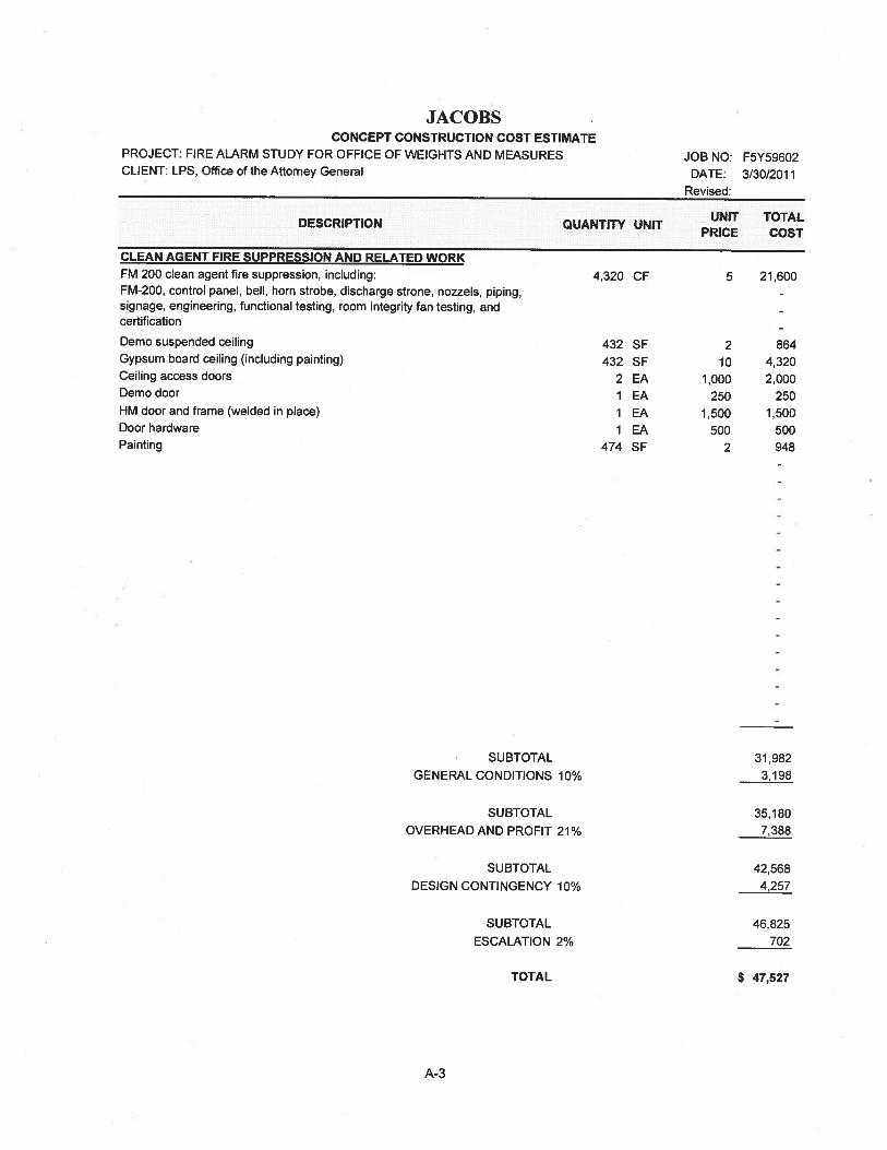
(I AN At’PMT FIRE SUPPRESSION AND RELATED WORKFM 200 clean agent fire suppression, including:FM-200, control panel, bell, horn strobe, discharge strone, nozzels, piping,signage, engineering, functional testing, room integrity fan testing, andcertification
JOB NO: F5Y59602DATE: 3/30/2011
Revised:
SUBTOTAL
GENERAL CONDITIONS 10%
SUBTOTAL
OVERHEAD AND PROFIT 21%
SUBTOTAL
DESIGN CONTINGENCY 10%
SUBTOTAL
ESCALATION 2%
31,9823,198
35,1807,388
42,5684,257
46,825702
$ 47,527
UNIT TOTALDESCRIPTION QUANTITY UNITPRICE COST
4,320 CF 5 21,600
Demo suspended ceilingGypsum board ceiling (including painting)Ceiling access doorsDemo door
HM door and frame (welded in place)Door hardwarePainting
432 SF432 SF
2 EA1 EA1 EA1 EA
474 SF
210
1.000250
1,500500
2
8644,3202,000
2501,500
500948
TOTAL
A-3
JACOBSCONCEPT CONSTRUCTION COST ESTIMATE
PROJECT: FIRE ALARM STUDY FOR OFFICE OF WEIGHTS AND MEASURESCLIENT: LPS, Office of the Attorney General
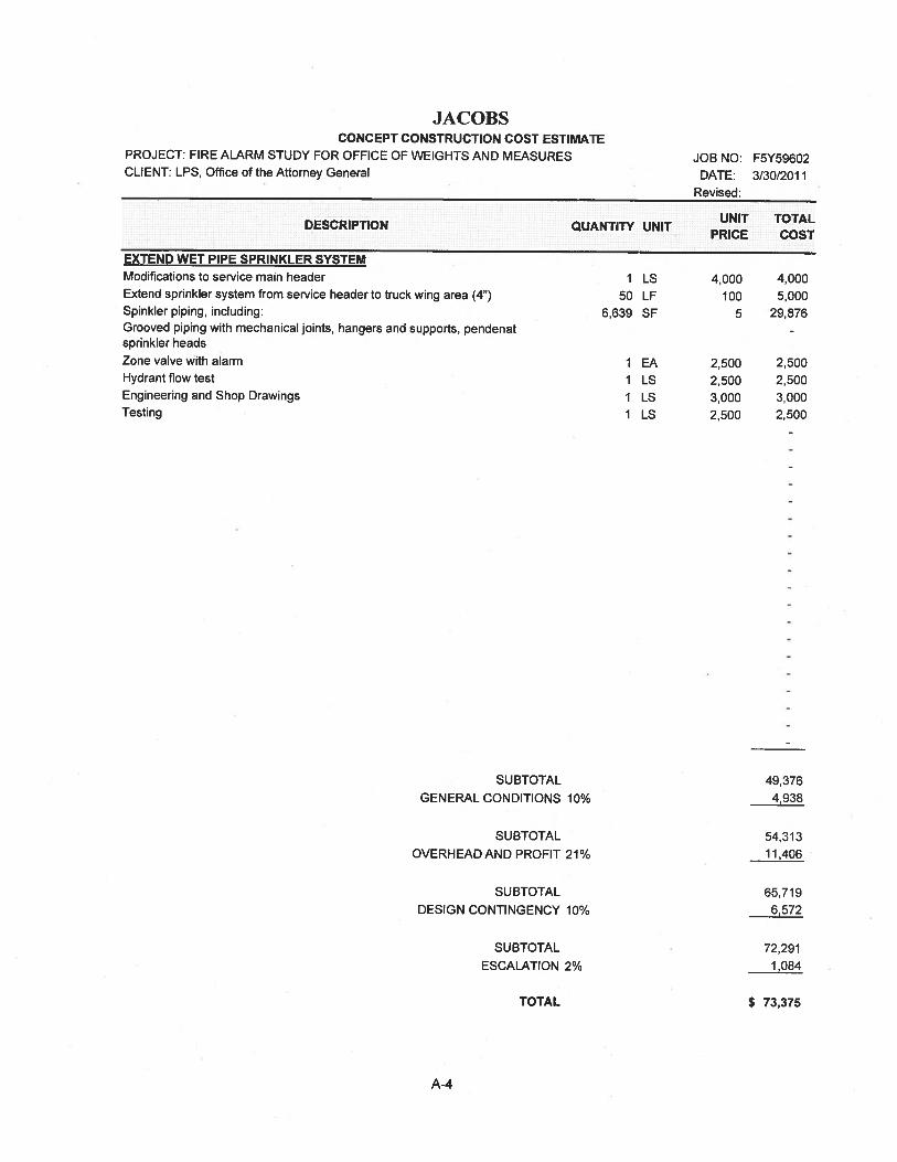
EXTEND WET PIPE SPRINKLER SYSTEMModifications to service main headerExtend sprinkler system from service header to truck wing area (4”)Spinkler piping, including:Grooved piping with mechanical joints, hangers and supports, pendenatsprinkler headsZone valve with alarmHydrant flow testEngineering and Shop DrawingsTesting
SUBTOTAL
GENERAL CONDITIONS 10%
49,3764,938
SUBTOTAL
OVERHEAD AND PROFIT 21%
SUBTOTAL
DESIGN CONTINGENCY 10%
SUBTOTAL
ESCALATION 2%
TOTAL
54,31311,406
65,7196,572
72,291
1,084
$ 73,375
UNIT TOTALDESCRIPTION QUANTITY UNITPRICE COST
JOB NO: F5Y59602DATE: 3/30/20 1 1
Revised:
I LS 4,000 4,00050 LF 100 5,000
6,639 SF 5 29,876
1 EA 2.500 2,5001 LS 2,500 2.5001 LS 3,000 3,0001 LS 2,500 2,500
A-4
Weights and Measures BuildingAvenel, NJFire Alarm and Fire Protection Systems Study
March 30, 2011
JACOBS
Photo IExisting Edwardsfire alarm controlpanel in BoilerRoom
Photo 2Existingannunciatorsection of firealarm control panel
Appendix — Photos
B-i
Weights and Measures BuildingAvenel, NJFire Alarm and Fire Protection Systems Study
March 30, 2011
Photo 3Typica’ existinghorn/strobe
Photo 4Typical existingmanual pull station
JACOBSB-2
Weights and Measures BuildingAvenel, NJFire Alarm and Fire Protection Systems Study