Intelligent Robotic Hand Design Project Number: ME-YMM-1236 DESIGN AND ANALYSIS OF A ROBOTIC HAND FOR USE AS A PROSTHETIC DEVICE A Major Qualifying Project Report Submitted to the Faculty of the WORCESTER POLYTECHNIC INSTITUTE in partial fulfillment of the requirements for the Degree of Bachelor of Science in Mechanical Engineering by Matthew J. Rowell _____________________________ Douglas D. Whitcomb _____________________________ Date: 4/27/06 Approved: ______________________________ Prof. Yong-Mo Moon, Major Advisor keywords 1. Prosthetic Hand 2. Robotic Gripper 3. Amputation
Transcript
Intelligent Robotic Hand Design
Project Number: ME-YMM-1236
DESIGN AND ANALYSIS OF A ROBOTIC HAND FOR USE AS A PROSTHETIC DEVICE
A Major Qualifying Project Report
Submitted to the Faculty
of the
WORCESTER POLYTECHNIC INSTITUTE
in partial fulfillment of the requirements for the
Degree of Bachelor of Science
in Mechanical Engineering
by
Matthew J. Rowell
_____________________________
Douglas D. Whitcomb
_____________________________
Date: 4/27/06
Approved: ______________________________ Prof. Yong-Mo Moon, Major Advisor
keywords 1. Prosthetic Hand 2. Robotic Gripper 3. Amputation
ii
I. Abstract
Current prosthetic devices to be used as a substitute for hands are inadequate to
the needs of amputees. The project team has designed a new prosthetic to be used in
conjunction with new signal processing technology that will meet current needs and
mimic all essential motion of the human hand. This design minimizes the number of
actuators by using a four-bar linkage design to control multiple joints.
iii
II. Table of Contents I. Abstract ....................................................................................................................... ii II. Table of Contents....................................................................................................... iii III. Table of Figures ..................................................................................................... iv 1. Introduction................................................................................................................. 1 2. Goal Statement............................................................................................................ 3 3. Task Specifications ..................................................................................................... 4 4. Background Research ................................................................................................. 5 5. Methodology............................................................................................................... 9 6. Final Design .............................................................................................................. 16 7. Analysis..................................................................................................................... 18 8. Prototype ................................................................................................................... 22 9. Results....................................................................................................................... 25 10. Conclusions............................................................................................................... 26 11. References................................................................................................................. 27 Appendix A....................................................................................................................... 28 Appendix B ....................................................................................................................... 34
iv
III. Table of Figures Figure 4.1 Several Different Prosthetic Hands Currently Available to Amputees ............. 5 Figure 4.2 Massa’s RTR II Prosthetic Hand [4] ................................................................. 7 Figure 5.1 Multiple Tension Cable Design Proposal........................................................ 10 Figure 5.2 Single Tension Cable Design Proposal ........................................................... 10 Figure 5.3 Multiple Pulley and Cable Controlled Design Concept .................................. 11 Figure 5.4 Pulley and Cable Control with Compliant Devices......................................... 11 Figure 5.5 Joint Rotation Provided by Cable System....................................................... 11 Figure 5.6 Concept Sketch of Knuckle Connection Piece................................................ 12 Figure 5.7 CAD Models of the Inner Knuckle Pieces (Left) and Outer Knuckle Pieces (Right) ............................................................................................................................... 13 Figure 5.8 Fourbar Linkage Design Approach to the Prosthetic Finger........................... 13 Figure 5.9Three Position Synthesis to Find Link Lengths and Ground Positions for Four-bar Linkage ....................................................................................................................... 14 Figure 5.10 Working Model Version of Four-bar Linkage .............................................. 15 Figure 6.1 Pro-engineer Model of Final Finger Design.................................................... 16 Figure 7.1 Transmission of the Linkage Over the Movement of the Finger .................... 20 Figure 7.2 Force Transmission of the Linkage with Improved Transmission Angle ....... 21 Figure 8.8.1 Assembled Prototype of the Prosthetic Finger ............................................. 22 Figure 8.8.2 Prototype Base for Fixturing and Testing .................................................... 23 Figure 8.8.3 Prototype Motion Comparison To That of an Actual Finger ....................... 24 Figure 8.8.4 Prototype Motion.......................................................................................... 24 Figure A.1 Drawing of Crank.prt...................................................................................... 29 Figure A.2 Drawing of Distal.prt...................................................................................... 30 Figure A.3 Drawing of Knuckle.prt.................................................................................. 31 Figure A.4 Drawing of Proximal.prt................................................................................. 32 Figure A.5 Drawing of Rocker.prt.................................................................................... 33 Figure B.1 Drawing of Prototype part: Base.prt ............................................................... 35 Figure B.2 Drawing of Prototype Part: Rocker.prt ........................................................... 36 Figure B.3 Drawing of Prototype Part: Distal.prt ............................................................. 37 Figure B.4 Drawing of Prototype Part: Joint.prt............................................................... 38 Figure B.5 Drawing of Prototype Part: Proximal.prt........................................................ 39 Figure B.6 Drawing of Prototype Part: Motorfixture.prt.................................................. 40 Figure B.7 Drawing of Prototype Part: Crank.prt............................................................. 41
1
1. Introduction The task proposed in this project is to design an intelligent prosthetic hand. An
intelligent prosthetic hand is defined as ‘a hand that mimics the natural movements of the
human hand.’ In order to appropriately mimic the motion of the human hand, we must
study its natural motions. For instance, the distal phalanx (finger tip) must rotate about
its joint as the middle phalanx rotates. It is very difficult and unnatural to bend the finger
at the proximal joint, while keeping the distal joint stiff. The motions of these two joints
are linked and must move together. On the other hand, the knuckle joint is not linked to
any other joints. The knuckle is able to move the entire finger with no motion in the
proximal or distal joints. This means that the finger can remain straight while bending at
the knuckle. The thumb is a very different digit. It only has a knuckle joint and a
proximal joint. These joints in the thumb are unlinked and can move independently of
each other.
Once the natural motions on the human hand are defined, the design of a
prosthetic that can imitate them can occur. In the design of this prosthetic, space is a very
important constraint. The size of the prosthetic must also resemble that of the average
human hand. This means that there is not much space to fit actuators and motors. The
fingers themselves are very small and there will not be any room for actuators that are
powerful enough to accomplish everyday tasks. This must be accounted for in the
prosthetics design. Some areas where actuators may be placed are in the body of the
hand or in the forearm of a full arm prosthetic. The scope of this project allows for
placement of actuators and motors in the forearm since the hand is being designed for a
2
full arm prosthetic. With preliminary research such as stated above, concepts for the
design can be developed to fit the criteria.
3
2. Goal Statement
The Goal of this project is to use our knowledge of the design process and
mechanics to design an intelligent prosthetic hand. The prosthetic hand should be able to
perform all useful tasks that the human hand can. It must be able to grip odd shaped and
delicate objects as well as resemble the human hand.
4
3. Task Specifications
1.) Prosthetic must resemble human hand in size and shape.
2.) Prosthetic must perform like human hand.
3.) Must fit actuators and motors in hand or forearm, not outside of hand or arm.
4.) Design must utilize standard parts where available.
5.) Design must incorporate the least amount of actuators and motors possible.
6.) Design must link the movements of distal and middle phalanxes.
7.) Design must account for over actuation.
5
4. Background Research
There are many reasons for the further production of prosthetic hands. According
to Massa [1], 30 to 50% of upper extremity amputees do not use their prosthetic hand on
a regular basis. There are a few reasons for this, the number one reason being low
functionality of the prosthetic. Most current prosthetic hands are simple grippers with
only two degrees of freedom, as shown in Figure 4.1.
Figure 4.1 Several Different Prosthetic Hands Currently Available to Amputees
Although this can be helpful to an amputee, there are still a great number of tasks
that can not be performed using such simple prosthetics. Another reason that prosthetic
hands are not used regularly is simply because of cosmetic reasons. Current prosthetics
do not resemble human anatomy. They are designed for function not for looks. A
prosthetic that resembled a human hand would be more beneficial to an amputee. A third
reason is that the current prosthetics are hard to control. Advanced prosthetics require
substantial training ,and feedback information to the user is poor. This lack of training
and feedback make for unnatural control of the hand [1].
Extensive research has been conducted on robotic hands and their application to
prosthetic hands [2]. There has been some success in the application of robotic fingers as
6
prosthetic fingers. There are a number of problems with these designs though. Most
robotic fingers have independent joint actuators for independent articulation. This
requires a large actuation and control system. The problem this poses is in packaging the
device in a small enough space to be inconspicuous. There often is not enough room for
many actuators in a prosthetic hand. If the design is for a lower arm amputee, then some
actuators can be placed in the lower arm. “Practical prosthetics can be designed by
sacrificing finger’s degrees of freedom [2].” It is possible to imitate the movement of the
human hand with out independent actuation of each joint. Each joint in a finger has a
linked relation with other joints rather than completely independent motion. This
relationship between joints can be utilized to design a practical robotic finger.
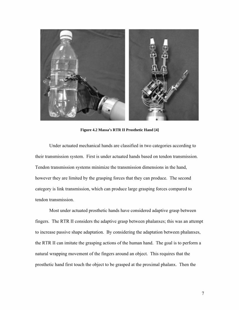
Massa [1] focuses on the development of a three fingered prosthetic called the
RTR II, shown in Figure 4.2. This prosthetic is capable of adaptive grasp, which is the
ability of the fingers and thumb to adapt to the shape of an object. The RTR II is an
under actuated mechanical hand. This means that the hand has less actuators than
degrees of freedom. Under actuated mechanisms lead to adaptive grasp when applied to
prosthetic hands. This, in turn, more closely resembles the actions of a human hand when
grasping an object.
7
Figure 4.2 Massa’s RTR II Prosthetic Hand [4]
Under actuated mechanical hands are classified in two categories according to
their transmission system. First is under actuated hands based on tendon transmission.
Tendon transmission systems minimize the transmission dimensions in the hand,
however they are limited by the grasping forces that they can produce. The second
category is link transmission, which can produce large grasping forces compared to
tendon transmission.
Most under actuated prosthetic hands have considered adaptive grasp between
fingers. The RTR II considers the adaptive grasp between phalanxes; this was an attempt
to increase passive shape adaptation. By considering the adaptation between phalanxes,
the RTR II can imitate the grasping actions of the human hand. The goal is to perform a
natural wrapping movement of the fingers around an object. This requires that the
prosthetic hand first touch the object to be grasped at the proximal phalanx. Then the
8
middle phalanx can bend around the object, and finally the distal phalanx. This order of
motions very closely resembles the behaviors of the human hand while grasping.
Other prosthetic hands make use of a passive adaptive grasp. This is a system that
mechanically controls the strength of the grasp depending on the shape and size of the
object. In this system each finger is driven by the same actuator. However, a series of
springs allow the fingers to move different amounts. This means that the hand can fit
more closely around objects with irregular shapes. The spring system also helps when
grasping delicate objects. The springs are able to absorb some of the force of the fingers
so the object does not [3].
Another type of grasp is active adaptive grasp. An active adaptive grasps uses
sensors and microprocessors rather than mechanical systems. In these systems, each
finger is fitted with a pressure sensor. Each actuator is fitted with a position sensor.
These sensors send feedback to a microprocessor that uses the information to control
each finger. This allows for each finger to be controlled individually giving greater
control. Also this allows for the hand to adapt to the object being manipulated. This type
of system can be fitted with a number of different actuators, such as DC motors (most
common), artificial muscle actuators, and pneumatic actuators. In addition to providing
motion in the hand, these actuators also give the joints stiffness. The stiffness in the joints
is controlled using transducers that produce feed back to a microprocessor [3].
9
5. Methodology
The first step we took when designing the prosthetic hand was to decide on the
best control mechanism for finger movement. The goal for our design was to minimize
the number of actuators necessary to control the movement of the finger and simplify the
equations needed to describe the motion of the finger. There are very many ways to do
this and we explored as many options as possible. There were several preliminary
designs we dealt with before choosing what we decided was the best approach. These
designs ranged from a tension controlled device, to pulley systems with different levels of
complexity, to a four-bar linkage design.
The first proposal, which was the tension controlled model, consisted of the three
joints of the finger, with a cable attached to a fixed point on each link of the finger which
was run back through the finger to an actuator mechanism at the hand or behind the wrist.
There were two main approaches to this design. The first, as shown in Figure 5.1,
consisted of cables run over the joints between each link of the finger, which would pull
the links upwards when tension was applied to each cable. For this model, each joint
would have a compliant mechanism which forced the resting state of the links to be in the
bent position. The second approach for this design has the complaint mechanisms such
that the resting state for the links is in the straightened positions. The tension from the
wire itself causes the finger to bend downwards, as shown in Figure 5.2.
10
Figure 5.1 Multiple Tension Cable Design Proposal
Figure 5.2 Single Tension Cable Design Proposal
A second design proposal included the use of pneumatic systems to drive the
bending or unbending of the fingers. In this proposal small tubes could be used to fill
with either air or liquid to actuate the finger. This proposal was eliminated early on in
our design process due to the noise inherent with pneumatic systems. The noise would
create the same discomfort for the user as non life-like prosthetics.
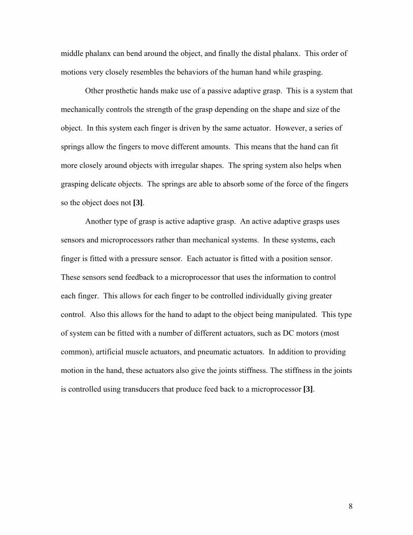
The third proposal for the finger design was a pulley system to control each joint
independently. Pulley’s would be placed at each joint in the finger, and would be
independently controlled by its own wire. Figures 5.3 and 5.4 show two approaches to
this method. In the second figure, the finger uses compliant devices to keep the finger
straightened at rest. Therefore, when the actuator is active, the fingers will bend and hold
their positions. When the actuator becomes inactive, the compliant mechanism would
return the fingers to their straightened positions. This eliminates the need for two
actuators per joint, and is thus preferable to the method shown in Figure 5.3, which
11
requires one actuator to bend the finger downwards, and a second actuator to return the
finger to the straightened position.
Figure 5.3 Multiple Pulley and Cable Controlled Design Concept
Figure 5.4 Pulley and Cable Control with Compliant Devices
In the designs described above, a pulley at each joint in the finger would have a
cable wrapped around it just enough for it to actuate the exact number of degrees of
rotation required at that joint. For instance, at the distal joint, the cable would run a full
90 degrees from the bottom of the pulley. This is shown in Figure 5.5. The angle
covered by the cable on the pulley varies for each joint.
Figure 5.5 Joint Rotation Provided by Cable System
12
Two different actuation methods were proposed for the cable system designs.
Either motors or flexinol actuating wire could be used to drive the motion provided by
the cables. We chose to use servo motors as opposed to the flexinol wire due to the high
operating temperatures of the flexinol wire. It may be possible to use flexinol in place of
the motors, but testing would need to be completed to confirm that overheating does not
occur and that temperatures of the prosthesis do not rise above the melting point of the
prosthetic skin covering.
One aspect of this design that we later incorporated into our final design was the
knuckle joint. This piece had to be designed so that it could provide space for the pulley
to rotate as well as allow the finger to rotate side to side. This piece also had to allow for
the actuating cables to pass through it on its path to the motors. The knuckle piece can be
seen in Figure 5.6 and 5.7. With this piece of the knuckle joint, the bending motions as
well as the lateral movements of the finger that we required are possible.
Figure 5.6 Concept Sketch of Knuckle Connection Piece
13
Figure 5.7 CAD Models of the Inner Knuckle Pieces (Left) and Outer Knuckle Pieces (Right)
The third, and final, approach to the design of the finger uses a four bar
mechanism to control the movement of the finger, and compliant mechanisms to move
the finger back to its resting state at the straight position. In this design, the four bar
linkage is placed between the two upper joints on the finger. This positioning of the
linkage can be seen in Figure 5.8. The purpose of the four bar linkage is to link the
motions of the upper two joints. As you may notice, the movement of the distal potion of
the human finger is not an independent movement. One can not bend at the distal joint
unless the finger is bent at the joint below it as well. Therefore, it was practical to link
the motions of these two joints, which reduced the number of actuators needed per finger.
With the four bar linkage design, there are only two actuating cables needed. One cable
is connected to the four-bar linkage, and the other one is connected to the pulley at the
knuckle joint between the proximal link and the hand.
Figure 5.8 Fourbar Linkage Design Approach to the Prosthetic Finger
14
Our first conclusion on the best design for the hand was that the cable system with
three independently actuated joints would be the best route to take. However, as we
progressed with our design, we realized that assembly of the cable system in a manner
that would best simplify the mathematical description of the motion of each finger would
be very difficult. Also, a slightly more complex method of limiting the actuators was
necessary when compared to the four-bar linkage design. Therefore, we chose to use the
four bar linkage design as a final concept.
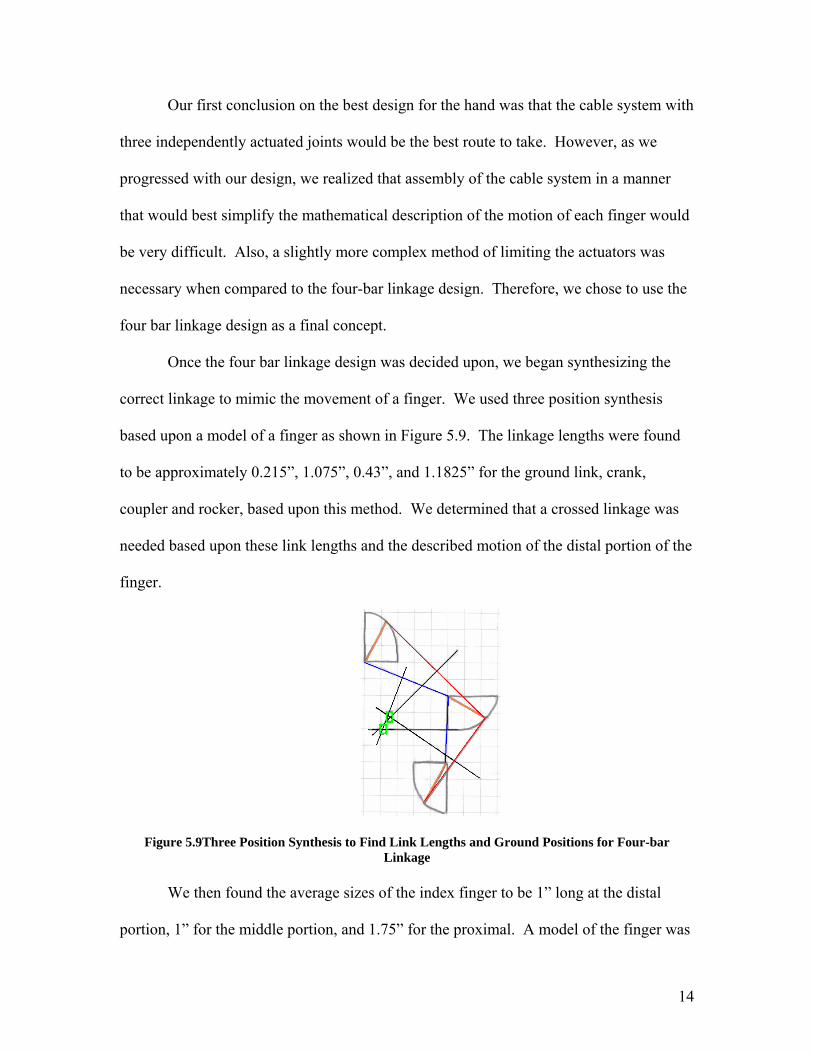
Once the four bar linkage design was decided upon, we began synthesizing the
correct linkage to mimic the movement of a finger. We used three position synthesis
based upon a model of a finger as shown in Figure 5.9. The linkage lengths were found
to be approximately 0.215”, 1.075”, 0.43”, and 1.1825” for the ground link, crank,
coupler and rocker, based upon this method. We determined that a crossed linkage was
needed based upon these link lengths and the described motion of the distal portion of the
finger.
Figure 5.9Three Position Synthesis to Find Link Lengths and Ground Positions for Four-bar Linkage
We then found the average sizes of the index finger to be 1” long at the distal
portion, 1” for the middle portion, and 1.75” for the proximal. A model of the finger was
15
then created in Working Model, as shown in figure 5.10, to check the link length values,
and then to further refine the link lengths and positions for the best design. The link
length ratios were then chosen to be 0.183”, 0.8”, 0.368355”, and 0.9” based upon our
results within Working Model. Producing lengths to within a thousandth of an inch or
within one hundred thousandth of an inch would prove impossible, and thus we limited
our dimensions to within one hundredth of an inch.
Figure 5.10 Working Model Version of Four-bar Linkage Once we determined that the design would adequately model that of a finger and
provide acceptable input force to output force ratios, we began modeling the actual
housing and configuration of the finger. From our preliminary research, we had
determined the approximate dimensions of a human index finger to be 0.5” around, with
the sections being 1.75” long, 1” long, and 1” long from proximal to distal. We began by
using simple geometries to obtain a rough approximation of the shape of the finger, and
added a spline to approximate the shape of the top of the finger.
16
6. Final Design
Figure 6.1 Pro-engineer Model of Final Finger Design
The final finger design consists of two knuckle versions, the proximal, distal,
crank, and rocker parts, as well as several shafts and shaft collars. All shafts have a
diameter of 0.0625”. One shaft each, of lengths 0.745”, 0.5”, 0.38”, 0.48”, 0.45”, and
0.26” was used as the pin for each joint, as well as the stop to prevent over actuation of
the finger.
The knuckle piece connects the assembled finger to the base structure of the hand.
The knuckle is then assembled onto the Proximal as shown in Figure 6.1. The crank and
rocker, shown as the yellow and black links in figure 6.1, are attached to the proximal
and distal portions of the finger. Small shaft collars lock these shafts in place so that they
cannot move out of position. The pin connecting the crank to the proximal also acts as a
stop for the rocker, preventing the distal portion of the finger from moving past the
straightened position when at rest.
The cable that controls the proximal portion of the finger wraps over the knuckle
piece and down around the drum, tying through the small hole drilled at the opposite side
of the drum. The cable that controls the middle and distal portion of the finger is fed
17
underneath the knuckle piece and through the proximal, and attaches to the first hole in
the middle of the crank after being guided under a small guide pin on the proximal piece.
Drawings for each of these parts can be found in Appendix A.
18
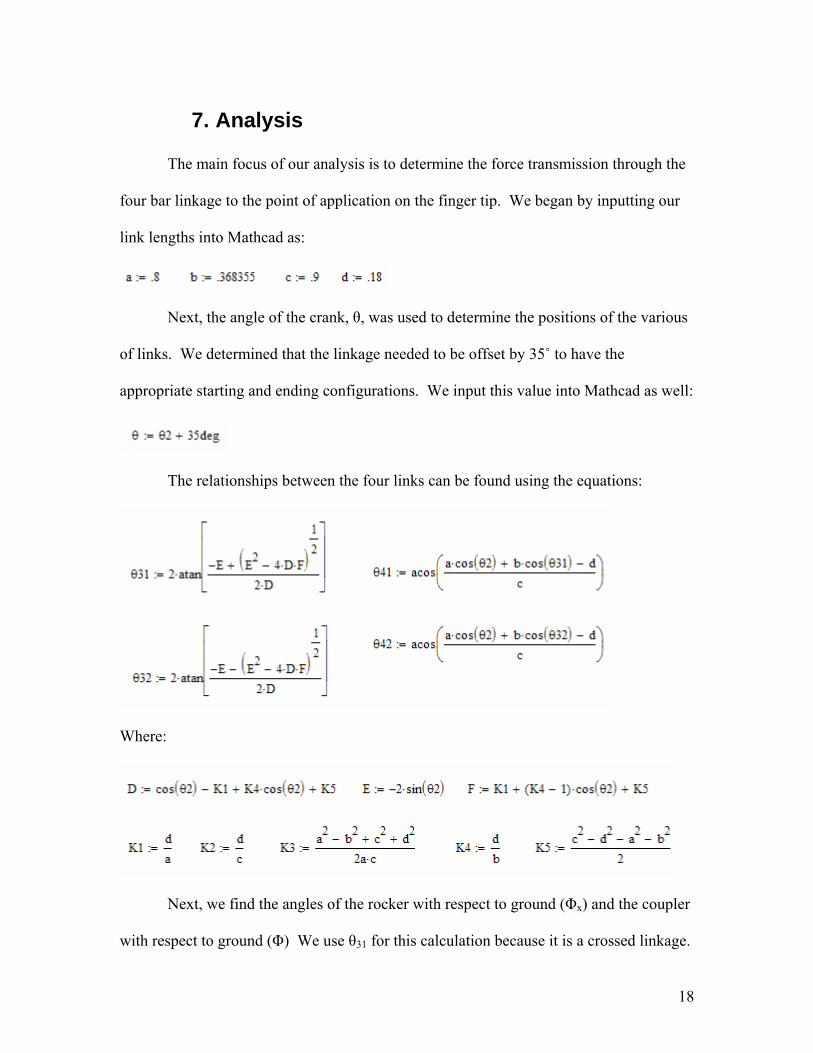
7. Analysis The main focus of our analysis is to determine the force transmission through the
four bar linkage to the point of application on the finger tip. We began by inputting our
link lengths into Mathcad as:
Next, the angle of the crank, θ, was used to determine the positions of the various
of links. We determined that the linkage needed to be offset by 35˚ to have the
appropriate starting and ending configurations. We input this value into Mathcad as well:
The relationships between the four links can be found using the equations:
Where:
Next, we find the angles of the rocker with respect to ground (Φx) and the coupler
with respect to ground (Φ) We use θ31 for this calculation because it is a crossed linkage.
19
Finally, we can determine the torque resulting from the tension of the cable
pulling on the crank and use it to determine the output force at the end of the crank with
respect to the input force:
Where θ2n is the angle of the crank with respect to the other links, not ground, Tin is the
torque resulting from the force applied by the cable, and Fr, Fry, and Frx are the total force
applied by the crank at the pivot between the crank and distal, the force in the y direction,
and the force in the x direction respectively.
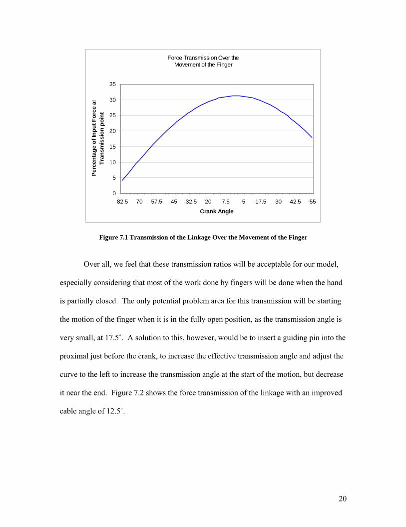
Using these relationships, we can choose an input angle and find the relationship
between the input force and output force. Our first test was to find what the ratio would
be at the worst case transmission angle. We determined this angle to be 82.5˚, when the
finger is straight. The crank travels from a position at 82.5˚ to -55˚ over the movement of
the finger from open to closed fist position. At the worst transmission angle, only 4.08%
of the input force will be transmitted to the end of the crank. However, for the best case
scenario, when the crank is at 0˚ with respect to ground, the percentage climbs to 31.25%
of the input force. Figure 7.1 shows the force transmission of the four bar linkage over
the full rotation of the crank.
20
Force Transmission Over the Movement of the Finger
Figure 7.2 Force Transmission of the Linkage with Improved Transmission Angle
As the graph shows, the initial output force can be increased to almost 10.7% of
the input force simply by increasing the angle at which the cable connects to the crank.
22
8. Prototype Once the final design of our hand was set, we began work on the prototype. At
first, we had hoped to have the proximal and distal pieces produced using rapid
prototyping methods. If this was possible, the proximal and distal pieces would be made
out of plastic and our links would be aluminum or, if possible, steel. Rapid prototyping
was not possible due to the small sizes of the parts and the relative strength of prototyped
plastic. Thus, we were forced to make all of the pieces out of aluminum in the WPI
workshop. The prototype for our design consists of one finger for the use of testing
gripping strength. To allow for easy testing, two motor mounts and a base piece were
design to assemble the prototype on. The full prototype can be seen in Figure 8.1.
Figure 8.8.1 Assembled Prototype of the Prosthetic Finger
As seen above, the prototype looks very different from our solid model of the
finger. Each piece of the finger was redesigned for ease of manufacturing using CAM
techniques coupled with hand machining. First of all, the entire finger was built with a
2:1 scale to make each piece easier to manufacture. The most notable pieces that needed
to be scaled were the links, as their small size was likely to cause tool bit breakage during
23
the machining process. Also, the proximal piece redesigned to include just the center
part. A pulley was purchased to replace the drum on the original piece. Two stoppers
were also added to the proximal piece to avoid the finger moving past the straightened
position. The distal piece was also substantially changed. The rounded edges of the
distal piece are very hard to manufacture from aluminum. Therefore, the distal piece was
made with squared edges. Each link was made by drilling holes in stock aluminum
sheets at the right distances from each other. Then, the links were simply cut out of the
aluminum sheet.
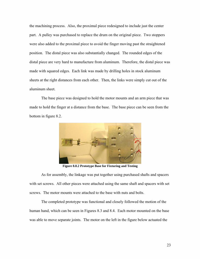
The base piece was designed to hold the motor mounts and an arm piece that was
made to hold the finger at a distance from the base. The base piece can be seen from the
bottom in figure 8.2.
Figure 8.8.2 Prototype Base for Fixturing and Testing
As for assembly, the linkage was put together using purchased shafts and spacers
with set screws. All other pieces were attached using the same shaft and spacers with set
screws. The motor mounts were attached to the base with nuts and bolts.
The completed prototype was functional and closely followed the motion of the
human hand, which can be seen in Figures 8.3 and 8.4. Each motor mounted on the base
was able to move separate joints. The motor on the left in the figure below actuated the
24
four bar linkage. This motor actuated the middle and distal joint. The front motor in the
figure below actuates the knuckle joint.
Figure 8.8.3 Prototype Motion Comparison To That of an Actual Finger
Figure 8.8.4 Prototype Motion
Drawings for each part of the assembly can be found in Appendix B. Standard shafts and shaft collars of diameter 0.125” were used for all shafts.
25
9. Results
The finger for a prosthetic hand has been designed to meet all of the original
specifications of the project. The finger design limits the number of actuators to the
fewest possible while allowing for full motion of the hand.
A prototype has been designed and built to test the finger design. Initial tests show
that the design produces the required motion, but has yet to be tested for input to output
force ratios. Observations have shown that without offsetting the crank cable angle the
motion of the finger will not commence. Thus, a guiding pin for the cable has been
designed into our final design, but has yet to be implemented into the prototype.
Further testing will be necessary to identify any further problems with the design
and specify the exact size of the motors necessary to drive the device.
26
10. Conclusions
A four-bar linkage design is a practical approach to limiting the number of actuators
necessary to drive a prosthetic hand. However, it may not be possible to produce the type
of forces necessary for a prosthetic hand using a four-bar linkage and motors small
enough to fit within the prosthetic device.
Other concerns include how to determine the amount of force that should be output
by the prosthetic, since there is no direct feedback to the controller. This can be
answered by several control solutions, including force sensors at the tips of the fingers
providing a feedback loop with the actuating control system set to not exceed a certain
maximum force. Other possibilities include calibrating the device to the individual,
because the control signals are being processed from the operator’s nerve endings in his
arm, it may be possible to adjust the output force based on the strength of those signals.
A final approach would be to use the approach currently used by many prosthetics, which
is to close each finger until it reaches an object, and then hold the finger’s position.
Once all of the concerns have been alleviated, and a model has been created based
upon our original design to be tested to scale, the next step will be to find an appropriate
skin cover for the device. Working with companies such as Livingskin and Alatheia
Prosthetics for their prosthetic skin would be beneficial for making the prosthetic as life
like as possible.
27
11. References [1] Design and Development of an Underactuated Prosthetic Hand. B. Massa, S. Roccella, M. C. Carrozza, P. Dario. International Conference on Robotics & Automation. Washington DC, May 2002 [2] Design and Control of a Robotic finger For Prosthetic Hands. Sang Eun Baek, Seung-Hi Lee, Joseph Heungsung Chang. International Conference on Intelligent Robots and Systems, 1999. [3] Mechatronics Case Study: Prosthetic Hand. Matthew Cook, Julian Duncan, Mike Gibbons, Ben Harvey, Graham Nicholson. February 2001. University of Surrey, Guildford, UK. [4] Experimental Analysis of the proprioceptive and exteroceptive sensors of an underactuated prosthetic hand. M. Zecca, G. cappiello, F. Sebastiani, S. Roccella, F. Vecchi, M. C. carrozza, P. Dario. ARTS Lab, Pontedera, Italy and INAIL RTR Centre, INAIL Prosthetic Center, Viareggio, Italy [5] TRS Inc. Boulder, Colorado. http://www.oandp.com/products/trs/, April 2006 [6] Alatheia Prosthetics, Brandon, Missouri. http://www.alatheia.com/, April 2006
28
Appendix A Drawings of the Final Design Parts CAD models and drawings of each part can be found on the enclosed CD.
29
Figure A.1 Drawing of Crank.prt
30
Figure A.2 Drawing of Distal.prt
31
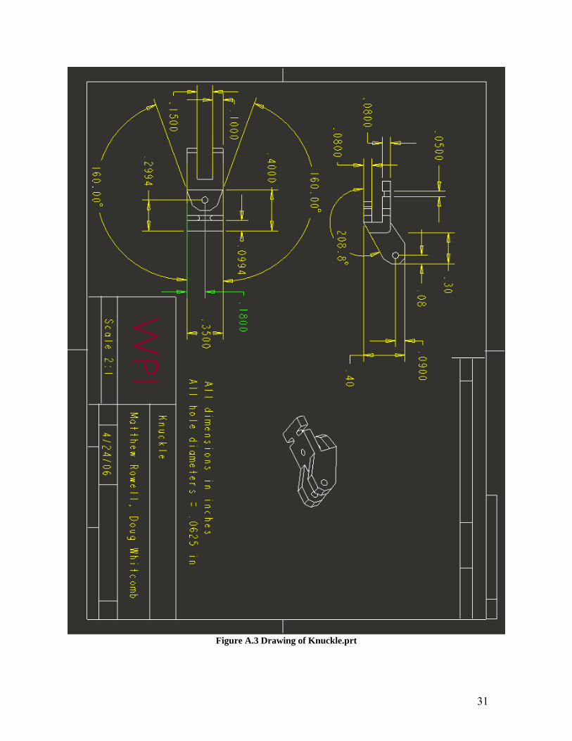
Figure A.3 Drawing of Knuckle.prt
32
Figure A.4 Drawing of Proximal.prt
33
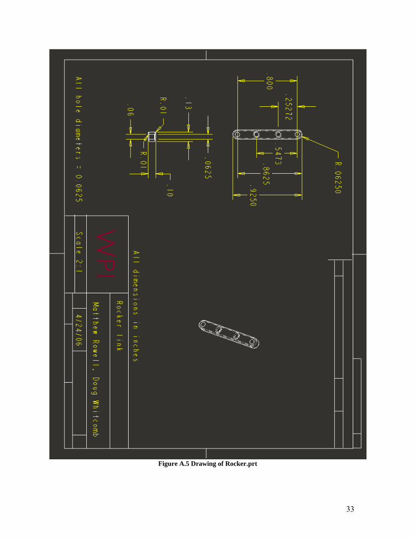
Figure A.5 Drawing of Rocker.prt
34
Appendix B Drawings of the Prototype Parts for Machining and Assembly. CAD models and drawings of each part can be found on the enclosed CD.
35
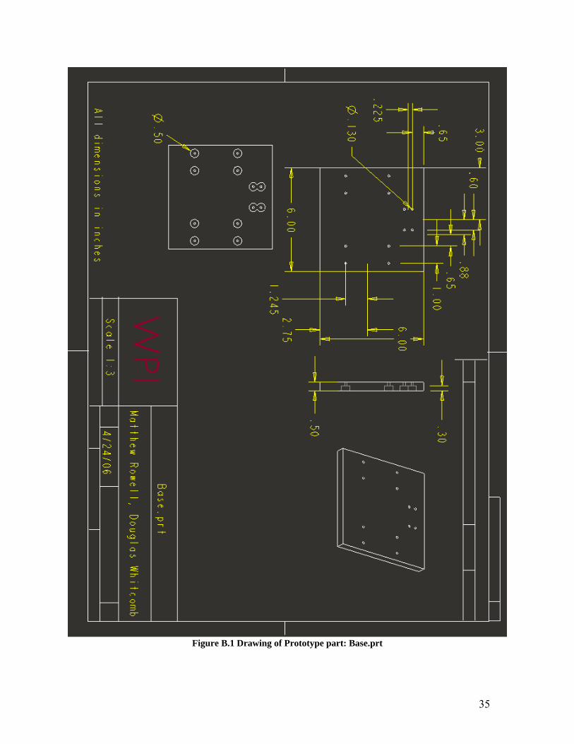
Figure B.1 Drawing of Prototype part: Base.prt
36
Figure B.2 Drawing of Prototype Part: Rocker.prt
37
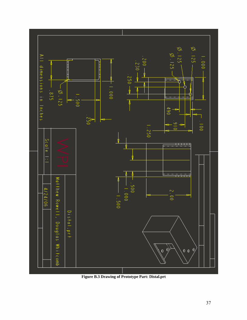
Figure B.3 Drawing of Prototype Part: Distal.prt
38
Figure B.4 Drawing of Prototype Part: Joint.prt
39
Figure B.5 Drawing of Prototype Part: Proximal.prt
40
Figure B.6 Drawing of Prototype Part: Motorfixture.prt


![1234-1236-1238 AC_os11_2009feb17[1]](https://static.documents.pub/doc/80x56/55cf8d265503462b13926575/1234-1236-1238-acos112009feb171.jpg)


