60
SECTION 2 | PROJECT DESCRIPTION PROJECT OVERVIEW PROJECT DESCRIPTION SECTION2

SECT
ION
2 | P
ROJE
CT D
ESCR
IPTI
ON
PROJECTOVERVIEW
PROJECT DESCRIPTIONSECTION2

2-i Jervois Base Metal Project
This page is intentionally left blank

1-1 Jervois Base Metal Project
Jervois Base Metal Project VOLUME 1 Project Overview
SECTION 2| Project Description
2 Description of the Project
2.1 Overview The Project will involve the extraction of ore from several deposits by open pit and underground mining methods, haulage of the ore to the on-site processing plant, processing to a concentrate which will be transported off site to the Alice Springs freight terminal. From there, ore will be rail freighted to Darwin or Adelaide for shipping to the market.
Detailed descriptions of the mine construction, mining operations, ore processing, tailings and waste rock management and other ancillary processes and activities proposed for the life of the Project are provided in the EIS Introduction and the following sections.
2.1.1. Project infrastructure Public roads leading to the Project are detailed in Section 2.1.1 and include the Stuart and Plenty highways and road number 194 to the mine access. Other roads in the vicinity of the Project include private property access tracks to water sources, cattle yards and the like.
Local airstrips include the privately owned Lucy Creek and Jervois Station airstrips and the Bonya airstrip (also referred to as the Baikal Airport) near the Bonya Community. An unused Jervois Mine airstrip is located in the north of the Project area. As part of the Project it is planned to upgrade the Bonya or the Lucy Creek airstrip to all weather standard and include a carpark, small departure shed and baggage area so it can be used to transport some workers and small quantities of supplies to site. If it is to be used to service the Project, the 14 kilometre access road from the Project to the Bonya airstrip will also require upgrading to all weather standard. The Lucy Creek airstrip remains an option for use by the Project as it can be used at night and is nominated as such by the Royal Flying Doctor Service whereas Bonya does not have this capacity as the nearby hills are within the safety corridor required for night operations.
Regional water bore information sourced from the NT Department of Environment and Natural Resources (DENR) indicate there are 309 bores spread across the Project area. Other bores within and adjacent to the Project include the Lucy Creek domestic water supply and stock watering bores, the community water supply near Orrtipa-Thurra (Bonya), and bores associated with the Lucy Creek Oil Well located approximately 45 kilometres (km) to the north-east and BMR Huckitta 8 which is located approximately 35 km to the northwest. Groundwater resources are discussed in detail in Sections 3.1, 4.4 and 4.5 of this EIS.
The only major local dam in the vicinity of the Project is the Jervois Mine Dam on Unca Creek which is estimated to have been constructed in the early 1970’s by Petrocarb for supplying mine process water. This dam will be used as a source of water for the Project following repairs to the dam wall to maintain the integrity of the wall in the long term.
Proposed infrastructure for the Project will include tailings storage facilities, a mine processing plant and associated support infrastructure, an upgraded accommodation village, administration buildings, new sediment catchment dams, access and haul roads, monitoring and supply bores, stockpiles, power generation and supply facilities, workshops, hardstands and laydown areas. Proposed infrastructure will be located over previously disturbed mine infrastructure areas wherever feasible.

Project Overview
SECTION 2 | Project Description 2- 2
2.2. Project Components
It should be noted that the information provided in this Section was current at the time of the preparation of the EIS and may change over time due to mine planning developments and exploration results.
Project Status
The Project is currently non-operational with exploration drilling being undertaken to update its Joint Ore Reserves Committee (JORC) compliant Reserves and Resources Statement (May 2018). Since acquiring the Project in 2011, KGL Resources has increased the estimated copper resource to 25.2 million tonnes, containing 384,800 tonnes of copper with 23.6 million ounces of silver at an average grade of 1.53% copper and 29.2 grams per tonne of silver. The contained copper has increased from that estimated in 2015 by 18% and the average grade has increased by 43%.
KGLs strategy is to increase the quality and size of the resource, and in particular increase the grade of the copper, whereby it can sustain a mining project before they make a decision to proceed to the development and reopening of the mine. The aim of the Project is to ensure it can be a robust, low cost producer with sustained viability during fluctuating markets.
The KGL Resources financial year 2017 Annual Report to Shareholders reported that the Project has progressed well for a second year with intensive drilling producing multiple high grade intersections at increased depth and laterally at Rockface. The Rockface mineralised zones have been expanded and the targeted drilling at Reward has continued to improve the quality of this deposit.
The Project was awarded major project status by the Northern Territory Government in 2017 which has assisted to facilitate the negotiation of government approval processes. Furthermore, an Indigenous Land Use Agreement (ILUA) with the Traditional Owners and the Central Land Council has been completed and registered with the National Native Title Tribunal (NNTT).
Life of Mine Schedule
The concept mine plan is potentially up to 15 years with initial mine planning and design using an initial mine life of 10 years. At the time of writing this EIS, the life of mine schedule was being optimised in conjunction with the mining contractor tender, so the schedule is subject to change. Furthermore, continued exploration drilling results have the potential to impact the overall life of mine schedule, and in particular the mining, rehabilitation, decommissioning and closure timeframes. The potential remains that the mine life will be expanded depending on exploration drilling results from the other potential mineralised zones.
• EIS completed – late 2018 • Construction – 2019-2020 • Commissioning – 2020 • Mining – 2020-2030 • Decommissioning and Closure – 2027-2030; and • Final Rehabilitation *– 2027-2030.
*Progressive rehabilitation will commence as areas become available throughout the life of the Project.
Initially KGL will focus on mining the Reward Open Pit and Rockface Underground and then progress to the Reward Underground, Bellbird Open Pit, Rockface Underground and the Bellbird Underground. More detail on the proposed mining sequence is provided below in Section 2.2.2.

Environmental Impact Statement
2-3 Jervois Base Metal Project
Geology
The Project comprises the mineralised deposits of Reward, Green Parrot, Bellbird, Bellbird North and Rockface as shown in Figure 2-1. Additional areas of mineralised zones are known on the site and could potentially be developed in future Projects.
Base metal mineralisation at Jervois is hosted by a lower-to-middle amphibolite grade metasedimentary sequence of the Bonya Metamorphics. The base metal mineralisation at Jervois is strata bound and contained within steeply dipping lenticular bodies (lodes) of calc-silicate, garnet-chlorite-magnetite rock and garnet-magnetite quartzite, within a thick succession of spotted andalusite-cordierite schist and quartz-sericite-magnetite schist. The mineralised sequence has a strike length of some 12 km and a stratigraphic thickness up to about 600 metres.
Mineralisation consists of veinlets and disseminations of chalcopyrite in the fresh zone with malachite/azurite/chalcocite in the oxide zone. In addition, smaller scale lenses of high grade galena (and sphalerite) semi-massive to massive mineralisation occur in fresh rocks with oxide equivalents including cerussite and anglesite. Generally these lenses are associated with more carbonate-rich host rocks occurring at Green Parrot, Reward and Bellbird North.
A more detailed description of the geology including mineralisation and extent of ore body of the Project is provided in Section 3.1. Waste rock is discussed in Section 2.2.5 below.
Project Footprint
Exploration Licence 25429 covers an area of approximately 3,800 hectares (ha) on the Jervois Pastoral Lease which equates to 1.28% of the pastoral lease. The total disturbance footprint for the Project will be approximately 970 ha (approximately 0.35% of the pastoral lease), of which 163.15 ha has been previously disturbed by historic mining activities dating back to 1929 as detailed in Section 1 of this EIS.
Mine infrastructure will include pits, waste rock landforms, tailings storage facilities, topsoil stockpiles, haul roads, heavy vehicle parking areas, Run of Mine (ROM) pads and fuel storage areas. The processing plant will include associated water tanks, workshops, fuel facilities, concentrate load out facility, mobile equipment, power plant, air and water supply facilities and storage areas. Other infrastructure associated with the project will include laydown areas, production and monitoring bores, a magazine and explosives store.
Temporary, transportable style buildings will be used for the following facilities:
• Mine office and administration buildings; • Crusher and plant control rooms; • Concrete batch plant; • Mess and ablution facilities; • Electrical substation buildings; • Workshop; • Warehouse; • Laboratory; • 12 megawatt diesel generator; • A 300 person accommodation village buildings; and • Concentrate, core and reagent storage sheds.

Project Overview
SECTION 2 | Project Description 2- 4
Figure 2-1 Proposed Project Infrastructure

Environmental Impact Statement
2-5 Jervois Base Metal Project
Site water infrastructure includes the existing Jervois Mine Dam which will be used as the Project water supply. Additional water will be sourced from a borefield to be developed near the project area. Water supply is discussed further in Section 2.2.8 below and Section 4.4 Hydrological Processes.
2.2.1. Mine Construction Open Pit Mine Construction Methods
Conventional open pit mining techniques will be applied to the Project development. The main mining activities will include:
• Vegetation and topsoil removal and management - optimising disturbed areas and with progressive rehabilitation where practicable, using excavators, bulldozers, loaders, graders and trucks.
• Construction of access roads and haul roads using the same equipment as above.
• Drilling and blasting waste rock and ore, generally on five metre high benches, using top-hammer diesel hydraulic drill rigs, with ANFO and emulsion explosives.
• Loading and hauling waste rock and ore by 190 tonne and 120 tonne excavators loading 90 tonne dump trucks. Ore will be hauled to the ROM crusher area adjacent to Reward Pit, and waste rock hauled to waste dumps adjacent to each pit.
• Grade control by advanced RC drilling.
• Stockpiling of different ore types.
• Open pit waste rock management.
• Surface water and groundwater management.
Open Pit Design Details
Conceptual open pit designs are computer-generated optimised pit shells with overall wall slopes derived from base case geotechnical design parameters, allowing for in-pit haul roads suitable for 90 tonne trucks. Two-lane roads would be 26 metres wide and single lane roads 17 metre wide, both with 1 in 9 gradients. The geotechnical design parameters are predicated on depressurised wall rock conditions and are summarised in the table below.
Further geotechnical and hydrogeological assessment is required to confirm that depressurisation of wall rocks can be practicably achieved.
Table 2-1 Open Pit Design Parameters
Pit Elevation Bench Face
Angle (°)
Bench
Height (m)
Bench
Width (m)
Inter Ramp
Angle (°) (excl
ramps)
Reward Surface to 340
mRL
55 20 (or less) 5 46.5
Below 340 mRL 80 20 10 55.9
Bellbird Surface to 340
mRL
55 20 (or less) 7 43.6
Below 340 mRL 80 20 10 55.9
Individual pit designs for the Reward and Bellbird deposits are shown in the following Figures.

Project Overview
SECTION 2 | Project Description 2- 6
Figure 2-2 Reward Open Pit and Waste Dump
Figure 2-3 Bellbird Open Pit and Waste Dump

Environmental Impact Statement
2-7 Jervois Base Metal Project
Underground Mine Construction Methods
Longhole stoping will be used to mine the underground deposits. Longhole stoping is an underground mining method often used in metalliferous mines which uses a production drill to drill holes to a pattern determined during the mine design phase of a project. Longhole stoping can cater for ore reserves which vary in thickness and gradient and is a highly selective and productive method of underground mining.
Access for equipment and personnel will be by decline, excavated by conventional drill and blast. Rockface decline will be developed from a portal in fresh rock in a boxcut excavated into the natural ground surface by drill and blast. The Reward and Bellbird declines will be developed from portals in fresh rock in the respective open pit walls. Detailed information on underground mine development is provided in Section 2.2.2.
Underground Mine Design Details
Access declines will be developed with 1 in 7 gradients, with a minimum 30 metre stand-off from the orebody for stability. The Reward and Bellbird portals will be developed in the open pit batters in fresh rock. Current preliminary designs for the underground mining incorporates 30 metre level from floor to floor.
Ground control in stopes will be a combination of cable bolts, pillars being left in narrower or lower grade areas of stopes and backfill. Backfill design will be completed in the next phase of project development in conjunction with optimisation of the stoping design and sequence. Backfill is likely to include cemented and uncemented rock fill, using development and open pit waste rock. Paste fill, using tailings, may also be considered for Reward Underground, located adjacent to the processing plant.
The Rockface underground operation will be established from a surface portal which, along with the intake and exhaust ventilation shafts, will be located part-way up the overlying ridge to assist with water management during the wet season.
The Rockface underground mine will be developed using a single decline, commencing from surface, with footwall drives established on 30 m sub-levels across the width of the orebody to the exhaust ventilation shaft. The second means of egress will be established through development of longhole raises between sub-levels within the decline footprint.
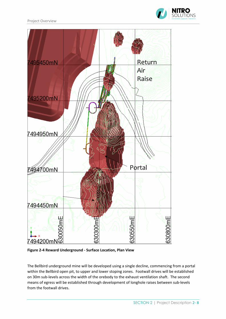
The Reward underground mine will be developed using a single decline, commencing from a portal
within the Reward open pit, to upper and lower stoping zones. The second means of egress will be
established through development of longhole raises between sub-levels within the decline footprint
in the lower stoping zone, and connecting into the footwall drives in the upper stoping zone.
Project Overview
SECTION 2 | Project Description 2- 8
Figure 2-4 Reward Underground - Surface Location, Plan View
The Bellbird underground mine will be developed using a single decline, commencing from a portal
within the Bellbird open pit, to upper and lower stoping zones. Footwall drives will be established
on 30m sub-levels across the width of the orebody to the exhaust ventilation shaft. The second
means of egress will be established through development of longhole raises between sub-levels
from the footwall drives.
Portal
Return Air Raise

Environmental Impact Statement
2-9 Jervois Base Metal Project
Figure 2-5 Bellbird Underground - Surface Location, Plan View
Waste Rock Dumps
Total amount of waste rock to be produced over the life of mine will be up to 87 million tonnes over current conceptual mine life. Waste rock dumps will be designed with 25 degree slopes with 20 metre lifts and a 10 metre berm left before each subsequent lift. The dump heights will be kept below a height of 40 to 60 metres above the natural surface. Estimated waste dump design volumes for the pits are detailed in Table 2-2.
Table 2-2– Estimated Waste Dump Design Volumes
Waste Dump Volume Reward 3.7 Mm3
Bellbird 10.2 Mm3
Rockface Up to 0.4 Mm3
The Reward waste dump has been designed to a height of approximately 56 metres above the natural surface. The Bellbird waste dump has been designed to a height of 40 metres above surface. A swell factor of 1.3 has been used to calculate the required volume for each waste dump in loose cubic metres (lcm) based on the pit designs. Waste rock characterisation and management is discussed in Section 2.2.5.

Project Overview
SECTION 2 | Project Description 2- 10
Tailings Storage Facility
The tailings storage facility will consist of two cells and will be constructed using mine waste and local borrow. The basin area will have a composite liner to achieve an appropriate level of seepage control. The low permeability compacted composite liner comprising HDPE and soil liner will be located below the operating supernatant pond. A basin underdrainage system will be incorporated to reduce seepage, increase tailings densities and improve the geotechnical stability of the TSF. The underdrainage system drains by gravity to a collection tower located at the lowest point in the TSF basin. Supernatant water will be removed from each cell of the TSF via a central decant tower abstraction system. Solution recovered from the decant system will be pumped back to the plant for re-use in the process circuit.
The TSF is designed following the ANCOLD “Guidelines on Tailings Dams” and are summarised in Table 2-3.
Table 2-3: ANCOLD Design Criteria Summary
Guideline
Requirement
Description of requirements Guideline
Reference
Extreme storm
storage
1 in 100 year AEP 72 hour duration storm with no
release, evaporation or decant.
ANCOLD 2012
Table 4
Contingency
freeboard
Wave run-up associated with a 1:10 AEP wind
velocity and an additional freeboard of 0.5 m
ANCOLD 2012
Table 5
Spillway
capacity
1 in 100,000 year Annual Exceedance Probability
(AEP) design flood with freeboard allowance to suit
wave run-up for 1:10 AEP wind velocity
ANCOLD 2012
Table 6
Design
earthquake
loading
OBE 1 in 1,000 year
MDE 1 in 10,000 year
Post Closure MCE
ANCOLD 2012
Table 7
Stability
minimum factor
of safety
Long term drained 1.5
Short term undrained
Downstream 1.5
Upstream 1.3
Post Seismic 1.0 – 1.2
ANCOLD 2012
Table 8
Dam safety/
inspection
frequency
Inspection by Dam Designer or equivalent qualified
Engineer - Annual inspections.
Routine inspections – daily to 3 times per week
ANCOLD 2012
Tables 9 and 10
ROM Stockpiles
The main ROM area will be located at the processing plant crusher adjacent to the Reward Open Pit on the existing ROM dump area constructed used by Plenty River Mining. Where possible, direct tipping from haul trucks into the primary crusher will be undertaken to limit stockpile areas and reduce double handling. However, there are several distinct ore types that may require specific blending strategies. It is therefore likely that separate ore stockpiling will be required prior to processing according to mill feed ore classifications as detailed in Section 2.2.3.
Additional stockpiles may be required to allow blending down of impurities such as bismuth, and any lead/zinc in copper ore. Ore stockpiles are also likely to be required from time to time at the Bellbird

Environmental Impact Statement
2-11 Jervois Base Metal Project
and Rockface areas. Ore to be hauled over a considerable haulage distance to the ROM area may be campaigned to improve haulage efficiency.
Detailed design for the ROM area and stockpiles, including factor of safety ratings will be completed during the next phase of the project detailed design development, taking account of the above considerations.
Mine Access and Haul Roads
The two main mine access roads to the mine are the processing plant and the accommodation village access roads which run from the Lucy Creek Access Road 194. These roads are approximately 3.5 km and 0.3 km respectively and are shown on Figure 2-1 Proposed Project Infrastructure. Based on the recommendations in the Traffic Impact Assessment (Appendix C-2), minimum 8.7 metre wide access roads to the Project will be provided, consisting of a single 3.7 metre wide unsealed lane with 2.5 metre shoulders. Detailed information on access road construction is provided in Section 2.2.7.
Haul roads will link the open pit and underground production operations with the waste dumps and
ROM pads. These haul roads will be for general vehicle and haul trucks with suitable design speeds
and local speed restrictions in key areas including around site infrastructure.
Design vehicle for cross-section, pavement design, horizontal and vertical alignment for site haul roads
will be a fully laden 90 tonne capacity haul truck. Minimum design standards for the haul roads will
be dual width designed for this size haul trucks as detailed in the below table. Final design will take
into consideration weather, ground conditions and drainage in each area, as well as availability of
suitable material for construction and maintenance
Table 2-4 Haul Road Design Standards
Truck Truck Width
(m)
Tyre Diameter
(m)
Bund Height
(m)
Bund Width
(m)
Drain Width
(m)
Minimum Running
Width (m)
Total Width
(m)
90t Haul Truck
6.49 2.68 1.34 4.68 1 22.72 28.4
Explosives Magazine
The explosives and detonator magazines and storage for security sensitive dangerous substances (SSDS) will be located between the Bellbird mining area and the main ROM area adjacent to the Reward Open Pit. Minimum design standards for storage and handling of explosives and SSDS will be according to the highest level defined by all relevant Australian and Northern Territory regulations, codes, guidelines and standards, including:
• Australian Standard AS 2187 Explosives storage, transport and use.
• Australian Standard AS 4326 The storage and handling of oxidizing agents.
• Australian code for the transport of explosives by road and rail (Australian Explosives Code).
• Australian code for the transport of dangerous goods by road and rail (Australian Dangerous Goods Code).
The location, layout and design for the explosives magazine and SSDS storage will be defined during the final design phase in conjunction with the mining contract tendering process, taking account of required exclusion distances as well as access for transportation.
Product Stockpiles and Other Significant Mine Infrastructure
Detailed design details, dimensions and design concepts for the product stockpiles will be completed in the next phase of project development, taking account of the above considerations. These designs

Project Overview
SECTION 2 | Project Description 2- 12
will be based on the stockpiles having a capacity of one months storage and a maximum of 10,000 tonnes of product to allow for suitable drainage.
A single integrated processing plant capable of processing the primary copper ores, the transitional copper ores and the lead/zinc ores will be constructed on site. Detailed design information on the processing plant is provided in Section 2.2.3.
Design details for other significant Project infrastructure, including the accommodation village and power station are provided in the following sections
Construction Input/Material Requirements
Infrastructure construction inputs needed to support the construction of the processing plant and the Project in general will be refined through the detailed mine planning process and will include those nominated in Table 2-5. Construction materials required will include modular water and fuel storage tanks, the power station components, modular buildings for the accommodation village and associated administration offices. Construction materials for hardstand areas and mine roads will be source from on site borrow pits and suitable waste rock material from mining pits.
Table 2-5 Project Construction Input Estimates
Description Quantity Unit
Processing Plant
Structural Steel 4,700 tonnes
Platework 92 tonnes
Field erected tanks 51 tonnes
Mechanical equipment 192 each
Conveyors 584 metres
Piping 30,500 metres
Buildings - Plant 3,327 m2
Buildings - Mining 372 m2
Diesel Fuel 6,500,000 litres
2.2.2. Mining Operations KGL intends to selectively mine the deposits by conventional open pit mining and decline access underground mining. The preliminary mine plan incorporates the following sequence to achieve the target production:
1. Mining will commence with concurrent development of the Reward open pit and Rockface underground.
2. Towards the end of the life of Reward open pit, development of Reward underground will commence from a portal in the Reward open pit wall. Ore production from Reward underground will ramp up as the Reward open pit production tails off.
3. Mining at Bellbird open pit will commence shortly after Reward underground development starts. The target production will then be maintained from Bellbird open pit, Rockface underground and Reward underground.
4. Towards the end of the life of Bellbird open pit, development of Bellbird underground will commence from a portal in the Bellbird open pit wall. This timing will coincide with the end of Rockface underground. Production from Bellbird underground will replace production from Rockface underground.

Environmental Impact Statement
2-13 Jervois Base Metal Project
5. The final stages of mine life for the initial plan will comprise production from Reward underground and Bellbird underground.
As detailed previously in Section 2.2, the life of mine schedule is yet to be optimised in conjunction with the mining contractor tendering process. The preliminary schedule shows total annual material movement of up to 10Mt in the first two years when Reward Open Pit is mined. However, the material movement rate decreases after this to a maximum of approximately 6Mt and there is some scope to reduce this further with advance pre-stripping at Bellbird Open Pit.
Figure 2-6 Life of Mine Material Movement
Project Overview
SECTION 2 | Project Description 2- 14
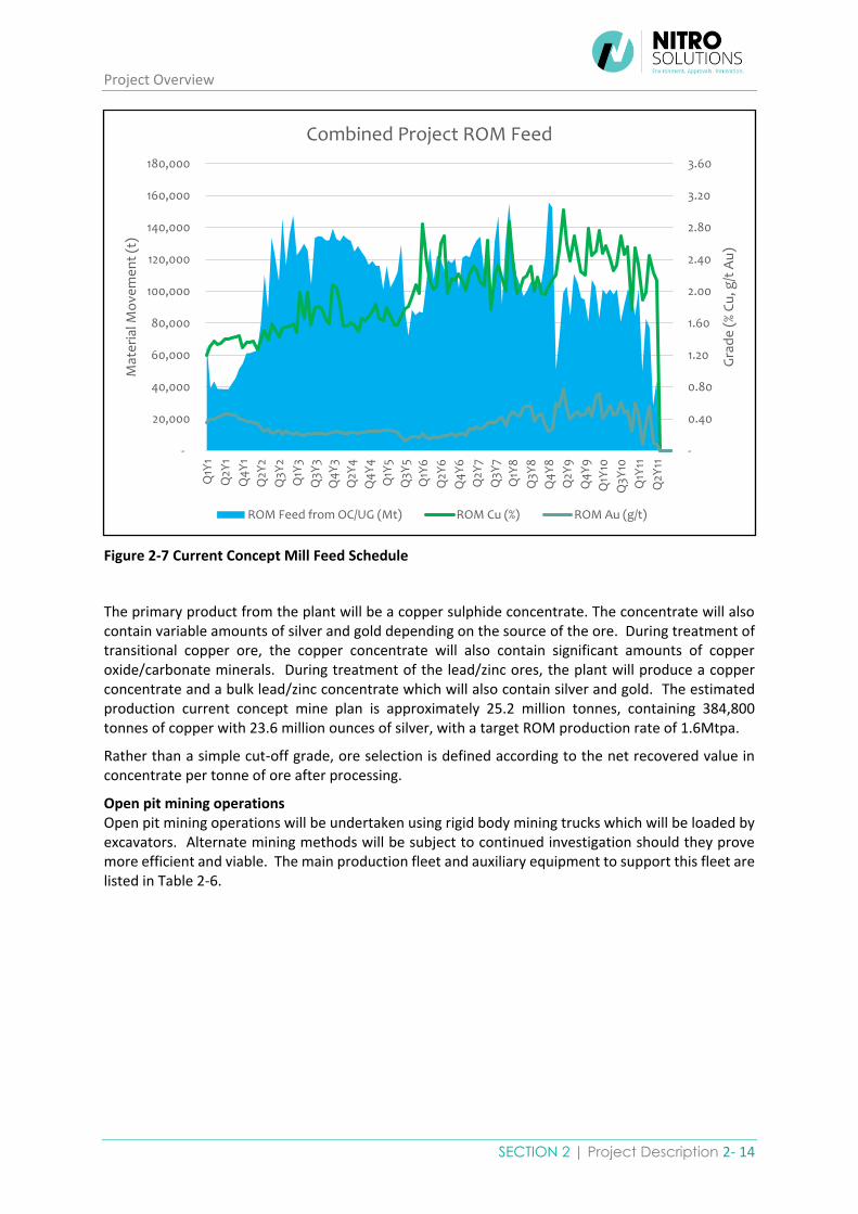
Figure 2-7 Current Concept Mill Feed Schedule
The primary product from the plant will be a copper sulphide concentrate. The concentrate will also contain variable amounts of silver and gold depending on the source of the ore. During treatment of transitional copper ore, the copper concentrate will also contain significant amounts of copper oxide/carbonate minerals. During treatment of the lead/zinc ores, the plant will produce a copper concentrate and a bulk lead/zinc concentrate which will also contain silver and gold. The estimated production current concept mine plan is approximately 25.2 million tonnes, containing 384,800 tonnes of copper with 23.6 million ounces of silver, with a target ROM production rate of 1.6Mtpa.
Rather than a simple cut-off grade, ore selection is defined according to the net recovered value in concentrate per tonne of ore after processing.
Open pit mining operations Open pit mining operations will be undertaken using rigid body mining trucks which will be loaded by excavators. Alternate mining methods will be subject to continued investigation should they prove more efficient and viable. The main production fleet and auxiliary equipment to support this fleet are listed in Table 2-6.
-
0.40
0.80
1.20
1.60
2.00
2.40
2.80
3.20
3.60
-
20,000
40,000
60,000
80,000
100,000
120,000
140,000
160,000
180,000
Q1Y
1
Q2Y
1
Q4
Y1
Q2Y
2
Q3Y
2
Q1Y
3
Q3Y
3
Q4
Y3
Q2Y
4
Q4
Y4
Q1Y
5
Q3Y
5
Q1Y
6
Q2Y
6
Q4
Y6
Q2Y
7
Q3Y
7
Q1Y
8
Q3Y
8
Q4
Y8
Q2Y
9
Q4
Y9
Q1Y
10
Q3Y
10
Q1Y
11
Q2Y
11
Gra
de
(%
Cu
, g/t
Au
)
Mat
eri
al M
ove
me
nt
(t)
Combined Project ROM Feed
ROM Feed from OC/UG (Mt) ROM Cu (%) ROM Au (g/t)

Environmental Impact Statement
2-15 Jervois Base Metal Project
Table 2-6 Open Pit Mining Equipment
Description Quantity
Open Pit Mining
Excavator 120t 2
Trucks 90t 4
Dozer D10 1
Grader 16 1
Watercart 50t 1
Integrated Tool Carrier 1
Loader 2
Batter Digger 1
Open Pit Drill and Blast
Production Rig 2
Integrated Tool Carrier 1
Manitou Fork Lift 1
AN Auger 1
Drill Support Truck 1
Lighting Plants 2
MMU Truck (ANFO / EMULSION) 1
Water Trailer (Dual Axle) 2
Light Vehicles 3
Access
Access will first be established by development of haul roads and other roads as required between the mine facilities area, open pits, separate underground portals, ROM pad and waste rock dumps. The roads will be constructed to an appropriate design to enable mining equipment to operate safely and productively. The design and construction will take into consideration of intended equipment, with suitable gradient, width, sub-base and road base, drainage, safety bunds and running surface.
Drill and Blast
The majority of materials mined in the pits will require some level of drilling and blasting for productive excavation. Drill and blasting performance will be affected by variable geology, structure (including faults, shears, joints and other fracturing) and water.
Blasts, including initiation, will be designed to comply with vibration and air pressure guidelines. A comprehensive blasting procedure will be developed as part of the mine safety management plan to ensure the safety of personnel and equipment in and around the mine during blasts.
Blasts will be fired on dayshift only. The exclusion zone for personnel around the blast will depend on the specifics of the shot and the material, however it is expected to typically be around 600 metres. A suitably qualified blasting expert will be engaged to confirm powder factors, provide initial blast designs, investigate fly-rock risk and provide preliminary blasting procedures.
Project Overview
SECTION 2 | Project Description 2- 16
Loading and Hauling
The load and haul operations will incorporate the following:
• Ore that is mined during the pit development prior to mill commissioning will be hauled and placed in a stockpile on the ROM pad adjacent to the Reward pit area for subsequent rehandling to the crusher.
• Bellbird is approximately four (4) km from the ROM area adjacent to the Reward pit. This distance is on the economic limits of hauling using dedicated mining trucks and may require a larger fleet of mining trucks, or alternative trucks for haulage to the ROM area.
• After commissioning of the processing plant, ore will be hauled to the ROM pad and either direct-tipped into the crusher or placed in a small stockpile on the ROM area.
• Waste rock will be hauled to a waste rock dump located adjacent to each open pit.
Grade Control
Grade control will be achieved through the following measures:
• Grade control geologists will identify zones that definitely would not contain ore, and other zones that may contain ore. Sampling, assaying and modelling of grades will assist with the effective delineation of the economic ore-waste boundaries.
• The most appropriate grade control system will be investigated and defined by the geological team and will likely involve grade control sampling by reverse circulation drilling in advance of the mining benches. Samples will be analysed in a laboratory on site and the assayed grades applied to the grade control block model to define ore zones.
• Optimum depth and spacing of the reverse circulation holes are expected to be between 5m and 10m and the depth between 15m and 30m.
• Grade control and marking out of ore zones will commence in the pre-production period during construction of haul roads and establishment of initial benches.
Open Pit Waste Rock Management
Waste rock landforms will be developed adjacent to each open pit. Where suitable waste rock will be used for construction purposes such as haul roads, hard stands and construction of embankments for the TSF. Waste rock with favourable characteristics will also be separately stockpiled for use in project closure related activities.
Underground mining operations
Equipment will be standard for underground mining operations and include those listed in Table 2-7.

Environmental Impact Statement
2-17 Jervois Base Metal Project
Table 2-7 Underground Mining Equipment
Description Quantity
Underground Production
Jumbo T1
Jumbo T2 1
Jumbo T3 1
Production Drill Rig 1 2
Production Drill Rig 1 1
Dev/Truck Bogger 1
Tele Bogger 1
Trucks 4
Prod Chargeup 1
Grader 1
Cable Bolter 1
Pump Truck 1
Light Vehicles 9
The preliminary underground mine design incorporates 30 metre level intervals and vertical stope spans of 35 metres. Ground control in stopes will be a combination of cable bolts, pillars being left in narrower or lower grade areas of stopes and backfill. Backfill is likely to include cemented and uncemented rock fill, using development and open pit waste rock. Paste fill, using tailings, may also be an option for Reward Underground as it is located adjacent to the processing plant depending on an economic assessment of this option.
Options for stope sequencing include:
1. Bottom-up long hole benching, with uncemented and cemented rock fill, or 2. Top-down longhole stoping, either
a. Leaving stopes open between permanent pillars, or b. With cement fill to allow full recovery
Bottom-up long hole benching has been adopted for the current mine plan. To maximise production rate, the underground mines have been divided into vertical panels. This provides concurrent production from multiple stoping areas. Within each panel stoping would progress from bottom upwards which reduces the requirement and cost for cement fill compared to full-recovery “underhand” top-down stoping.
Ore drive development will consist of a drive located centrally within the stope. An alternative method or addition to be considered will be the development of a footwall drive on most levels with access to the ore drives at multiple points along the strike. Further work is underway to optimise the stope design and sequencing.
Pit dewatering will likely be required through the installation of a sump (or sumps) below the operating bench to which most water will flow and then be pumped to holding tanks or ponds on the surface.

Project Overview
SECTION 2 | Project Description 2- 18
Underground Waste Rock Management
The waste material mined from underground will be disposed of preferentially in underground voids and used as backfill when possible rather than disposed of on the surface to reduce the footprint of the site. Waste mined during early stage development at Reward and Bellbird will be dumped in the pit or trucked to the surface. Over the life of mine, more waste material is required as backfill underground than is mined through waste development.
Vegetation and Topsoil Management
A Topsoil Management Plan will be developed as part of the Environmental Management Plan provided in Section 5 and incorporate the mine closure phase. Topsoil and vegetation management principles will include:
• Optimising disturbed areas and progressive rehabilitation;
• Backfilling where this can be undertaken without adverse economic impact;
• Final landscape and future land use of open pit voids and rehabilitated areas;
• Sediment and water controls to be established before vegetation and soil is disturbed;
• The sparse vegetation will be progressively cleared ahead of haul road development, open pit mining and waste placement operations to minimise the cleared footprint of the operations and to limit sediment and dust generation from erosion;
• The limited topsoil of suitable quality for rehabilitation, potentially the top 200mm over part of the mining area, would be removed separately to the underlying dirt and rock materials. This will be achieved by using excavators, bulldozers, loaders, graders and trucks. Where possible it will be used directly on areas requiring rehabilitation, otherwise it will be stockpiled for future use. Stockpiles will be up to 2 metres high with 1 (vertical):3 (horizontal) batters. The topsoil from clearing of the open pit and waste dumps will be located around the planned waste dump footprint;
• When activity has ceased in part of a disturbed mining area, rehabilitation will commence in that area if this does not impact on, or be impacted by, ongoing mining operations. Rehabilitation will include:
o Rehandling and placement of suitable topsoil from stockpiles or direct placement from currently cleared areas;
o Spreading of topsoil; o Revegetation by seeding and/or transplanting of seedlings, and/or natural
revegetation, as deemed suitable; o Topsoil will not be replaced on batters and other excavated surfaces that are too steep
for the safe operation of equipment. These surfaces will be left to revegetate naturally.
Topsoil will be cleared from open pit and waste dump areas and stockpiled as near as possible to the planned rehabilitation areas to reduce handling and transport requirements.
Topsoil will be reapplied by trucking it to dump crests and pushed down or pushing it up the dump face with a dozer, or a combination of these two methods to achieve the most productive outcome.
2.2.3. Ore Processing
Mined material will be delivered to the ROM or where possible, tipped directly into the primary crusher to reduce the need for rehandling. The ROM ore bin located adjacent to the processing plant will be fed by a front-end loader with material fed by a primary feeder and reclaim unit to the primary crusher. A mill feed conveyor will transport material directly to the SAG mill.
Ore will be stockpiled on the ROM pad according to ore type categories and grade, including: • Low grade copper oxide / transitional rock;

Environmental Impact Statement
2-19 Jervois Base Metal Project
• Low grade copper fresh rock; • High grade copper oxide / transitional rock; • High grade copper fresh rock; and • High grade lead/zinc fresh rock.
The primary product from the plant will be a copper sulphide concentrate. The concentrate will also contain variable amounts of silver and gold depending on the ore source. During treatment of transitional copper ore, the copper concentrate will also contain significant amounts of copper oxide/carbonate minerals.
Processing methods will include a single integrated processing plant capable of processing the primary copper ores, the transitional copper ores and the lead/zinc ores. The plant will be capable of processing up to 1.6Mt of ore (ROM) per annum to produce approximately 150,000 tonnes of base metal concentrate per annum (both a copper concentrate and a lead/zinc concentrate).
The processing plant will comprise of the following principal process areas: • Primary crushing, crushed ore storage and reclaim • Primary grinding and classification • Copper Rougher and scavenger flotation • Copper regrind • Copper cleaner and scavenger flotation • Copper concentrate thickening and filtration • Lead/Zinc Rougher and Scavenger Flotation • Lead/Zinc regrind • Lead/Zinc cleaner and scavenger flotation • Lead/Zinc concentrate thickening and filtration • Concentrates storage and load-out • Tailings thickening, disposal and decant water return • Process water storage and distribution • Raw water storage and distribution • Reagent make-up and distribution • High and low pressure air distribution.
The plant will incorporate a conventional comminution circuit comprising a primary crusher, followed
by a semi-autogenous grinding (SAG) mill and a ball mill (SAB combination) which will operate in closed
circuit with a cyclone cluster as described below. Layout of the proposed plant site is shown in Figure
2-8 and a schematic flowsheet for the processing plant is shown in Figure 2-9.
Crushing
Run of mine (ROM) ore will be transferred via a wheel loader from the ROM pad over a slotted static
grizzly screen into a 70-tonne capacity ROM bin. An apron feeder will feed the ore from the ROM bin
to the jaw crusher. A conveyor will be used to transfer the crushed ore to a 70-tonne capacity crushed
ore bin with the overflow transferred by another conveyor to an emergency crushed ore stockpile.
Grinding
The crushed ore will be fed to a SAG mill at which is operated at variable speed. Slurry discharging
from the SAG mill will feed over a trommel screen where undersize discharges into a cyclone feed
hopper and diluted through the addition of process water, before being pumped to a bank of 2
operating (1 standby) hydrocyclones. Overflow from the trommel screen is recycled back to the feed
of the SAG mill via a conveyor.
Underflow from the hydrocyclones will be fed to the ball mill which will operate at a fixed speed.
Discharge from the ball mill will be fed over a trommel screen, where the undersize discharges into
the cyclone feed hopper and combined with the SAG mill discharge stream.

Project Overview
SECTION 2 | Project Description 2- 20
Overflow from the hydrocyclone will feed to the copper rougher flotation circuit.
Copper Rougher Floatation
The copper rougher circuit consists of a conditioning tank and a rougher tank cell and six rougher
scavenger tank cells.
Overflow from the grinding circuit hydrocyclone will gravity flow over a static trash screen before
passing through to a copper flotation conditioning tank fitted. Collector which is an organic compound
that adheres to the copper mineral causing the mineral to become hydrophobic (water repellent), is
added to the conditioning tank. This allows the copper mineral to adhere to the air bubbles produced
when air is added to a flotation tank. Sodium metabisulfite is also added to the conditioning tank to
depress the lead/zinc associated minerals during the copper flotation recovery stage.
From the conditioning tank the slurry is fed to the rougher flotation tank cell. A frother is added to
the rougher tank cell as well as low pressure air. The conditioned copper mineral is attracted to the
air bubbles which floats to the surface, is separated from the slurry and collected at launders located
within the tank cell. The material collected at the launder is referred to as concentrate. The remainder
of the slurry in the tank cell gravity flows to the next tank in series.
Concentrate from the first rougher cell launder is captured and diverted to the concentrate transfer
hopper where it combines with the concentrate from the cleaner circuit. Slurry discharging the
rougher tank cell gravity flows to the first of the six rougher scavenger tank cells. These tank cells
operate in a series configuration and the concentrate from each tank cell is combined and transferred
to the regrind circuit.
The copper tailings slurry discharges from the last scavenger train and gravitates to the final copper
tails hopper. From the tails hopper the slurry is pumped to the lead/zinc flotation circuit.
Copper Regrind
Copper rougher and cleaner scavenger concentrate is combined in the regrind circuit hydrocyclone
feed hopper and process water is added to regulate the slurry density. The mixed concentrate slurry
is pumped to the regrind cyclone cluster. The fine fraction reports to the cyclone overflow and
gravitates to the copper cleaner conditioning tank. The regrind cyclone underflow gravity flows to the
vertical regrind mill. A portion of the regrind mill discharge is returned back into the regrind mill and
the remainder discharges into the hydrocyclone feed hopper for further size classification in the
regrind cyclones.
Copper Cleaner Circuit
The copper cleaner circuit consists of a conditioning tank, four tank cells and two cleaner scavenger
tank cells. An organic collector, similar to the one added to the rougher conditioning tank and lime
slurry, used for pH control are added to the cleaner conditioning tank and mixed with the regrind
cyclone overflow slurry. Following conditioning the slurry gravity flows to the cleaning circuit.
Concentrate from four cleaner cells are combined with the concentrate from the first rougher cell and
this referred to as the final concentrate.
Slurry from the last cleaner cell gravity flows to the first cleaner scavenger cell. The concentrate from
these cells is combined and pumped back to the regrind circuit.
Slurry discharging the last cleaner scavenger cell can be pumped to either the final copper tails hopper
and combined with the copper rougher tail or pumped to the first copper rougher scavenger cell.

Environmental Impact Statement
2-21 Jervois Base Metal Project
The copper flotation circuit tailings feeds into the lead/zinc rougher flotation circuit.
Copper Concentrate
The final copper concentrate from the copper flotation circuit is pumped to a dedicated copper
concentrate thickener, via the concentrate thickener feed hopper. The concentrate thickener feed
hopper de-aerates the concentrate slurry prior to thickening. Flocculant is added to the thickener
feedwell to produce conglomerated particles and promote quick settling. Solids are compacted at the
base of the thickener and raked to the centre cone at the bottom of the thickener and discharged.
The thickened concentrate is pumped to the filter feed tank. The solution separated from the solids
reports to the thickener overflow launder where it gravity flows to the process water storage tank for
re-use.
The thickened copper concentrate slurry is pumped from the filter feed tank to the dedicated copper
vertical plate and frame filter. The copper filter produces a concentrate cake by reducing the
concentrate moisture content. Filtrate from the filter is pumped to the process water tank.
The copper concentrate cake discharges from the filter into a bunker where it is picked up by a wheel
loader and tipped into half height shipping containers. The containers are covered and placed on a
prime mover using a reach stacker.
Lead/Zinc Rougher Flotation
The lead/zinc rougher circuit consists of a conditioning tank and five rougher tank cells, in series.
A relatively low addition of copper sulphate, at neutral pH, is added to reactivate the lead/zinc
associated minerals and a combination of collector 1, for lead associated minerals and collector 3, for
the zinc associated minerals, are added to the conditioning tank prior to the roughing stage of the
circuit.
Similar to the copper rougher flotation circuit, the conditioning tank slurry is fed to the lead/zinc
rougher flotation circuit where frother is added to the rougher tank cell as well as low pressure air.
The conditioned lead/zinc minerals are attracted to the air bubbles which float to the surface,
separated from the slurry, and collected at launders located within the tank cell as concentrate. The
remainder of the slurry in the tank cell gravity flows to the next tank in series.
Concentrate from the first rougher cell launder is captured and diverted to the concentrate transfer
hopper where it combines with the concentrate from the cleaner circuit. Slurry discharging the
rougher tank cell gravity flows to the first of the six rougher scavenger tank cells. These tank cells
operate in a series configuration and the concentrate from each tank cell is combined and transferred
to the regrind circuit.
The lead/zinc tailings slurry discharges from the last scavenger train and gravitates to the final tails
hopper. From the tails hopper the slurry is pumped to the tailings thickener.
Lead/Zinc Regrind
Rougher and cleaner scavenger concentrate is combined in the regrind circuit hydrocyclone feed
hopper and process water is added to regulate the slurry density. The mixed concentrate slurry is
pumped to the regrind cyclone cluster. The fine fraction reports to the cyclone overflow and the
overflow gravitates to the cleaner conditioning tank. The regrind cyclone underflow gravity flows to
the vertical regrind mill. A portion of the regrind mill discharge is returned pumped back into the
regrind mill and the remainder discharges into the hydrocyclone feed hopper for further size
classification in the regrind cyclones.

Project Overview
SECTION 2 | Project Description 2- 22
Lead/Zinc Cleaner Circuit
The lead/zinc cleaner circuit consists of a conditioning tank, two cleaner tank cells and three cleaner
scavenger tank cells.
Following conditioning, the slurry gravity flows to the cleaning circuit where the five tank cells operate
in series. Concentrate from the first two cleaner cells is treated as final concentrate and pumped to
the concentrate thickener.
Slurry from the last cleaner cell gravity flows to the first cleaner scavenger cell. The concentrate from
these cells is combined and pumped back to the regrind circuit. Slurry discharging the last cleaner
scavenger cell can be pumped to either the final tails hopper and combined with the rougher tail or
pumped to the first rougher scavenger cell.
Lead/Zinc Concentrate
The final lead/zinc concentrate from the lead/zinc flotation circuit is pumped to a dedicated lead/zinc
concentrate thickener via the concentrate thickener feed hopper. The concentrate thickener feed
hopper de-aerates the concentrate slurry prior to thickening. Flocculant is added to the thickener
feedwell to produce conglomerated particles and promote quick settling. Solids are compacted at the
base of the thickener and raked to the centre cone at the bottom of the thickener and discharged.
The thickened concentrate is pumped to the lead/zinc filter feed tank. The solution separated from
the solids reports to the thickener overflow launder where it gravity flows to the process water storage
tank.
The thickened lead/zinc concentrate slurry is pumped from the filter feed tank to the dedicated
lead/zinc vertical plate and frame filter. The lead/zinc filter produces a concentrate cake by reducing
the concentrate moisture content. Filtrate from the filter is pumped to the process water tank.
The lead/zinc concentrate cake discharges the filter into a bunker where it is picked up by a wheel
loader and tipped into half height shipping containers which are placed on a prime mover using a
reach stacker.
Tailings from the lead/zinc rougher and cleaner scavenger cells are pumped to a thickener. The tailings
are combined with flocculant and thickened. The thickened tails are pumped to the tailings storage
facility where the solids settle. Overflows from the concentrate and tailings thickeners are pumped
to a process water tank to be reused within the processing plant.

Environmental Impact Statement
2-23 Jervois Base Metal Project
Figure 2-8 Proposed Plant Layout
Source: Sedgman Pty Limited. (2018).
Figure 2-9 Processing Schematic Flowsheet
Source: Sedgman Pty Limited. (2018). Engineering & Consulting Services Jervois Copper Project Pre-Feasibility Study CapEx & OpEx Report.
Materials and consumables associated with the processing plant will include liners for the primary crusher, SAG, Ball and regrind mills, filter cloths, reagents and diesel fuel. Estimated annual reagent

Project Overview
SECTION 2 | Project Description 2- 24
for the Project at peak production volumes are provided in Table 2-8. Diesel fuel volumes for the Project are provided in Section 2.2.7.
Table 2-8 Estimated Consumable Volumes
Consumable Volume Unit
Collector 1 - Sodium di-isobutyl dithiophosphinate (Aerophine 3418A or similar)
2 m3
Collector 2 - Sodium di-isobutyl-dithiophosphate (Aero 3477 or similar)
2 m3
Frother - Glycol ether or similar 2 m3
Flocculant 2 m3
Hydrated lime 135 tonnes
SAG Mill Grinding Media 40 tonnes
Ball Mill Grinding Media 40 Tonnes
Water Requirements, Treatment and Sources
Raw water will be sourced from the Jervois Mine Dam and the Project borefield. Water will be stored in a plant raw water pond to be used for:
• Fire water; • General distribution; • Reagent make-up; • Potable water treatment; • Gland service; • Cooling water (SAB); and • Process water make-up.
Process water will be recycled from thickeners in the processing plant and the decant water return from the TSF and topped up from raw water as required. There will be a process water tank for temporary storage and duty/standby pumps will be installed to supply process water to all areas of the plant.
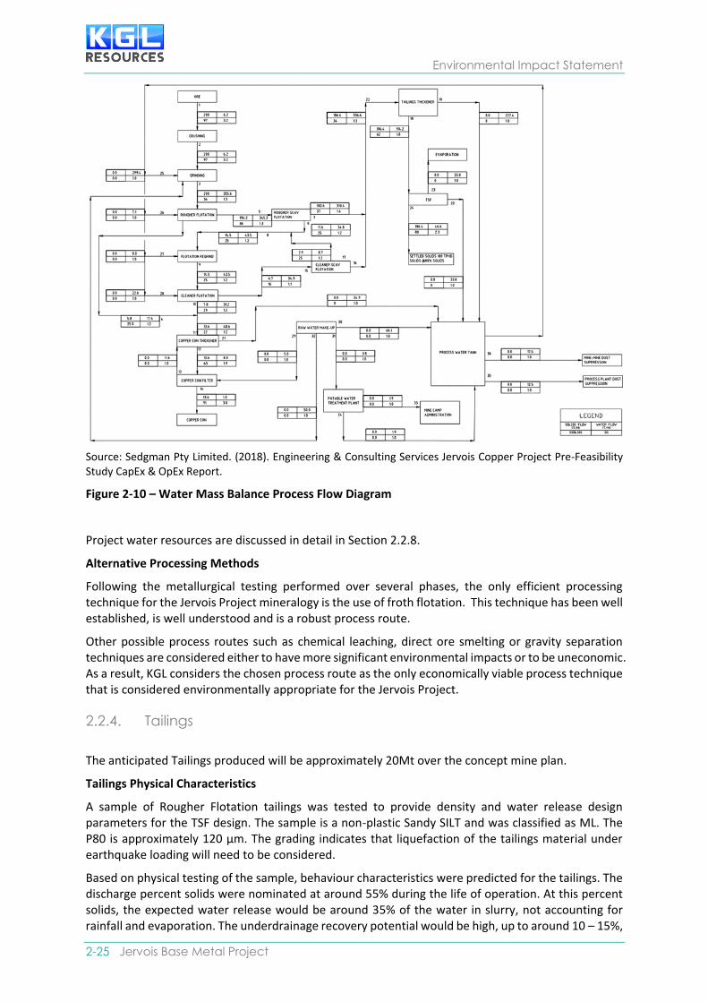
Based on the water mass balance process flow diagram for the Project (Sedgman, 2018) the predicted water demand rate to the Potable Water Treatment Plant is 3.8 T/h (0.1 ML/d or 36.5 ML/year), while the processing plant is projected to require a constant water demand rate of 86.1 T/h (2.05 ML/d) over the life of the Project, which includes:
• 55 T/h (1.3 ML/d or 475 ML/year) of raw water (plant standard); and
• 31 T/h (0.75 ML/d or 274 ML/year) of process water (mine affected water or sediment laden water).
Environmental Impact Statement
2-25 Jervois Base Metal Project
Source: Sedgman Pty Limited. (2018). Engineering & Consulting Services Jervois Copper Project Pre-Feasibility Study CapEx & OpEx Report.
Figure 2-10 – Water Mass Balance Process Flow Diagram
Project water resources are discussed in detail in Section 2.2.8.
Alternative Processing Methods
Following the metallurgical testing performed over several phases, the only efficient processing technique for the Jervois Project mineralogy is the use of froth flotation. This technique has been well established, is well understood and is a robust process route.
Other possible process routes such as chemical leaching, direct ore smelting or gravity separation techniques are considered either to have more significant environmental impacts or to be uneconomic. As a result, KGL considers the chosen process route as the only economically viable process technique that is considered environmentally appropriate for the Jervois Project.
2.2.4. Tailings
The anticipated Tailings produced will be approximately 20Mt over the concept mine plan.
Tailings Physical Characteristics
A sample of Rougher Flotation tailings was tested to provide density and water release design parameters for the TSF design. The sample is a non-plastic Sandy SILT and was classified as ML. The P80 is approximately 120 µm. The grading indicates that liquefaction of the tailings material under earthquake loading will need to be considered.
Based on physical testing of the sample, behaviour characteristics were predicted for the tailings. The discharge percent solids were nominated at around 55% during the life of operation. At this percent solids, the expected water release would be around 35% of the water in slurry, not accounting for rainfall and evaporation. The underdrainage recovery potential would be high, up to around 10 – 15%,

Project Overview
SECTION 2 | Project Description 2- 26
depending on the extent of the underdrainage collection system and basin conditions. A typical achievable density of 1.2 t/m³ is expected for the early phase of the project increasing to 1.4 - 1.45 t/m³ during the later stages.
Tailings Geochemical Characteristics
Geochemical testing results suggest that tailings from sulphide ore samples will have moderate S values of around 1% S, and are likely to be PAF. Tailings showed enrichment in a similar suite of metals/metalloids as the waste rock and ore, including Ag, Bi, Be, Cd, Co, Cs, Cu, Fe, Mn, Pb, S Mo, Se, Tl, W and Zn. Some mobilisation of Cd, Co, Cu, SO4, Mn and Zn can be expected during the lag period.
Results indicate that the following preliminary segregation criteria based on total S only could be used for routine classification:
NAF: ≤ 0.4%S
PAF: > 0.4%S
where PAF represents combined NAF-HS, PAF-LC and PAF classes
The proposed TSF design is based on the ANCOLD Guidelines on Tailings Dams – Planning, Design, Construction, Operation and Closure 2012 and is summarised in Section 2.2.1. Details on TSF design is outlined in the Appendix C-12: Tailings Storage Facility Design Report.
Rehabilitation and Closure
Tailings will be paste backfilled into underground workings preferentially to reduce the inventory of tailings requiring surface management. Preferably on closure, tailings will be returned to the pit void. Further studies will be carried out in the detailed planning stage to investigate the feasibility of the preferred TSF rehabilitation option.
An alternative option for TSF rehabilitation will be to install a basic store and release cover system to isolate the tailings from the environment as suggested in Appendix C-12 Tailings Storage Facility Design Report. This will comprise the following nominal design concepts:
• A low permeability layer over the surface of the tailings to reduce water movement into and out of the tailings;
• A store and release layer to provide water storage after storms for later us by vegetation or removal by evaporation;
• A topsoil layer will be integrated into the surface of the store and release layer for vegetation growth;
• Thickness of layers will be determined based on material selection and climatic conditions.
2.2.5. Waste Rock Characterisation
The operations are anticipated to produce approximately 87 Mt of waste rock over the current concept mine plan.
Waste Rock Characterisation
Geochemical testing of the waste rock characterisation has been carried out as part of the PFS and the EIS. Results show that the Project open cut and underground mine waste rock materials will comprise mainly NAF material, accounting for 70% of the waste rock samples tested. This proportion does not reflect the true proportion of materials to be mined, and the overall proportion of NAF waste rock material is expected to be higher. A smaller portion of PAF (including PAF-LC and NAF-HS) materials occur mainly within a halo around the sulphidic ore. These materials should be readily visually identified, with S a good discriminator. A summary of ARD potential by waste rock unit based on results to date is provided below:
• Oxide Waste Rock: NAF with occasional zones of PAF/PAF-LC
Environmental Impact Statement
2-27 Jervois Base Metal Project
• Transition Waste Rock: NAF with occasional zones of PAF/PAF-LC
• Distal: NAF with occasional zones of PAF/PAF-LC
• Proximal: NAF with common zones of PAF/PAF-LC
• Mineralised: Mixed NAF and PAF/PAF-LC
• Felsic: NAF; and
• Vein (Quartz/Tourmaline): NAF with common zones of PAF/PAF-LC.
Specialised testing indicated the presence of iron carbonate, resulting in slow reaction rates and variable ANC effectiveness. Despite this, kinetic NAG testing of PAF materials indicated significant lag times before acid conditions develop after exposure to atmospheric oxidation. Longer lag times would provide flexibility in management of waste rock seepage during any temporary storage or short-term exposure during operations.
Sulphidic waste rock material show strong enrichment in a variety of metals/metalloids including Ag, Bi, Be, Cd, Co, Cs, Cu, Mo, Pb, S, Se, Tl, W and Zn with enrichment increasing with proximity to ore. A number of samples were also enriched in Fe and Mn, and individual samples were enriched in As, Ag, As, Bi, Cd, Cu, Hg, Pb, Sb, Se, Tl and Zn.
Waste Rock Management
Proposed waste rock dumps are outlined in Figure 2-1. Waste rock landforms will be developed to exiting disturbance area where possible and adjacent to each open pit. Where suitable waste rock will be used for construction purposes such as haul roads, hard stands and construction of embankments for the TSF. Waste rock with favourable characteristics will also be separately stockpiled for use in project closure related activities. Sediment dams will be constructed to capture and manage runoff from waste rock dumps. Most waste rock from pit and underground development is expected to be NAF and environmentally benign, and will not require specific management for control of AMD. The smaller portion of PAF material will be selective handled, including:
• In pit or underground disposal below recovery water table levels;
• Selective underground disposal of PAF as part of paste backfill; or
• Construction of an infiltration control cover system in-pit or ex-pit.
The waste material mined from underground will be disposed of preferentially in underground voids and used as backfill when possible rather than disposed of on the surface to reduce the footprint of the site. Waste mined during early stage development at Reward and Bellbird will be dumped in the pit or trucked to the surface.
Contingency for treatment during operations include dump surface limestone addition and/or blending to help delay onset of acid drainage, and/or collection of seepage/runoff and treatment.
Visual Amenity
The Project area lies within the Jervois Range and is characterised by rugged hills, narrow plains, low erosional hills and rises, bold sandstone ranges and undulating stony plains. As previously outlined, the Project has been subject to historic mining activities for many years. As a result of these activities, there are significant existing disturbance across the site (figures 2-11 to 2-13). Waste rock dumps have the potential to impact the visual amenity of the area, although this will be somewhat diminished given the surrounding landscape and the level of existing disturbance across the site.

Project Overview
SECTION 2 | Project Description 2- 28
Figure 2-11 Jervois Landscape
Figure 2-12 Historic Mining Disturbance

Environmental Impact Statement
2-29 Jervois Base Metal Project
Figure 2-13 Historic Mining Disturbance
Rehabilitation and Revegetation
Final waste rock dumps will be stabilised with resilient, self-sustaining native vegetation of local provenance. Geotechnical assessments will be carried out to ensure waste rock dumps are physically stable. A monitoring program will be undertaken to demonstrate waste rock dumps have no adverse impact to the quality and quantity of surface water, groundwater and water-dependent ecosystems.
Progressive rehabilitation of disturbed areas during operation will be undertaken if they are no longer required for mining. Revegetation and rehabilitation trials on disturbed areas will be conducted to evaluate the most effective techniques. An auditable timeline for rehabilitation trials, including seed bank investigations and testing of seed viability for the Project will be developed by KGL.
Areas progressively rehabilitated will be carefully monitored for evidence of the introduction and establishment of weeds, with the objective of identifying and treating them before they become persistent.
A monitoring program will be implemented post-rehabilitation to ensure rehabilitation objectives and criteria are met.
Pits will be mined using conventional open pit methods. The extent to which the pits will be backfilled and progressively rehabilitated will be dependent upon the detailed mining schedule and the economic viability of backfilling, such as haulage distance for backfilling.
The PAF waste material mined from underground will be disposed of preferentially in underground voids and used as backfill where possible rather than being disposed of on the surface to reduce the footprint of the site. In pit dumping will be the preferred option for the PAF waste mined during early stage development at Reward and Bellbird.
The tailings will be paste backfilled into underground workings preferentially to reduce the inventory of tailings requiring surface management. Preferably on closure, tailings will be returned to the pit void. Detailed studies will be carried out in the detailed planning stage to investigate the feasibility of the preferred TSF rehabilitation option.
2.2.6. Non-mineral Waste Characterisation Waste streams associated with the Project will include solid and liquid wastes generated by construction, operational and general mine activities. These waste streams will include:
• General waste including miscellaneous items and putrescibles from warehousing, workshop, administration, crib hut and accommodation facilities;
• General recyclable waste such as paper, cardboard, recyclable plastics, glass and aluminium and steel cans from administration, crib hut and accommodation facilities;
• Scrap steel and metal including drums, cut-offs, containers and hardware (bolts, screws, etc) from plant and workshop activities;
Project Overview
SECTION 2 | Project Description 2- 30
• Hydrocarbons such as oils, greases, oily water, oil and fuel filters, oily rags and absorbent materials, hoses, coolants, drums, detergents, reagents, solvents, paints and resins generated by the workshop and field service activities;
• Waste chemicals such as non-hydrocarbon materials and reagents from the workshop, laboratory and processing plant;
• Waste tyres;
• Waste batteries;
• Sewage and grease trap waste from administration, crib hut and accommodation village facilities;
• Concrete, bricks and other inert waste;
• Industrial plastics such as used pipeline and off cuts, liners; and
• Wood products such as timber, pallets and off cuts.
Recyclable waste will be collected in designated bins and areas, collected and disposed of at off-site recycling collection points by licensed contractors. Recyclable wastes will include:
• Class 1, 2, 5 plastics
• Aluminium and steel cans
• Cardboard
• Paper
• Recyclable glass bottles
• Pallets; and
• Scrap metal such as Light and heavy gauge steel.
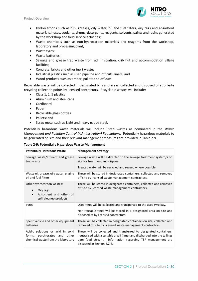
Potentially hazardous waste materials will include listed wastes as nominated in the Waste Management and Pollution Control (Administration) Regulations. Potentially hazardous materials to be generated on site and their relevant management measures are provided in Table 2-9.
Table 2-9: Potentially Hazardous Waste Management
Potentially Hazardous Waste Management Strategy
Sewage waste/effluent and grease trap waste
Sewage waste will be directed to the sewage treatment system/s on site for treatment and disposal.
Treated water will be recycled and reused where possible.
Waste oil, grease, oily water, engine oil and fuel filters
These will be stored in designated containers, collected and removed off site by licensed waste management contractors.
Other hydrocarbon wastes:
• Oily rags
• Absorbent and other oil spill cleanup products
These will be stored in designated containers, collected and removed off site by licensed waste management contractors.
Tyres Used tyres will be collected and transported to the used tyre bay.
Non-reusable tyres will be stored in a designated area on site and disposed of by licensed contractors.
Spent vehicle and other equipment batteries
These will be collected in designated containers on site, collected and removed off site by licensed waste management contractors.
Acidic solutions or acid in solid forms, perchlorates and other chemical waste from the laboratory
These will be collected and transferred to designated containers, neutralised with a suitable alkali (lime) and discharged into the tailings dam feed stream. Information regarding TSF management are discussed in Section 2.2.4.

Environmental Impact Statement
2-31 Jervois Base Metal Project
Potentially Hazardous Waste Management Strategy
Storage and handling of these hazardous substances will be carried out as specified in the relevant MSDS, including regular inspection and maintenance of storage areas.
Reagents used for processing in the processing plant, including process water
Process water will be recycled and reused where possible with excess process water to be discharged into the tailings dam. Information regarding TSF management are discussed in Section 2.2.4.
Containers that are contaminated with residues of listed waste
Any containers that are used to collect listed waste will be collected in designated areas or containers on site, collected and removed off site by licensed waste management contractors.
Soils contaminated with a listed waste
Any soils that are contaminated by listed waste as a result of spillages will be collected in designated containers on site, collected and removed off site by licensed waste management contractors.
All incidents will be reported in accordance with the Health and Safety Management System.
Tailings Information regarding tailings and TSF management are discussed in Section 2.2.4.
Hydrocarbon and flammable material
Hydrocarbon and flammable materials will be stored according to the requirements of AS1940-2004 The Storage and Handling of Flammable and Combustible Liquids.
Any spillage will be cleaned up using spill kits and waste will be collected in designated containers on site, collected and removed off site by licensed waste management contractors.
All incidents will be reported in accordance with the Health and Safety Management System.
Potentially hazardous substances that will be used on site include reagents for ore processing and will include:
• Sodium di-isobutyl dithiophosphinate (Aerophine 3418A or similar)
• Sodium di-isobutyl-dithiophosphate (Aero 3477 or similar)
• Frother - Glycol ether or similar
• Flocculant
• Hydrated lime
• SAG and ball mill grinding media
• Diesel
• Acidic solutions and/or acids in solid form
• Perchlorates and other chemicals in the site laboratory
• Fire suppression chemicals
• Copper and other concentrate products; and
• Explosives.
Storage and handling of hazardous substances will be carried out as specified in their relevant MSDS. Storage facilities will be subject to regular inspections and housekeeping to ensure the integrity of the facilities are maintained. Storage, transport and use of explosives on site will be conducted in accordance with AS 2187 Explosives Code – Northern Territory. Detail on the management of hazardous substances is provided in the Environmental Management Plan in Section 5.
Procedures for transport and storage of hazardous substances will be implemented as part of the Health and Safety Management System and will be in accordance with the requirements of the
Project Overview
SECTION 2 | Project Description 2- 32
Transport of Dangerous Goods by Road and Rail (National Uniform Legislation) Act 2016 and Transport of Dangerous Goods by Road and Rail (National Uniform Legislation) Regulations 2016. All vehicles will be registered and fitted with spill kits, PPE and first aid kits as required. All incidents will be reported according to the requirements of the Health and Safety Management System.
The design of onsite sewage treatment plant will follow AS/NZS 1547:2012 On-site Domestic
Wastewater Management 2012, AS/NZS 1546.1 Australian Standard On-site domestic wastewater
treatment units: Septic Tanks 2008 and the Australian guidelines for Water Recycling: Managing
Health & Environmental Risks (Phase 1) 2006. The sewage treatment facility will be licensed by the
Northern Territory Department of Health. Approvals will be obtained following the Draft Guidelines
for Wastewater Works Design Approval of Recycled Water Systems 2014 and Guidance for Completion
of Wastewater Works Design Approval Applications.
Scrap tyres awaiting transport for take-back and recycling will be stored in designated tyre storage areas which will be isolated from other combustible or flammable materials to reduce the potential for fires. Grass and other flammable materials will be removed around the radius of the tyre storage area.
The removal of listed wastes off site will be conducted by appropriately licensed waste companies who are authorised to collect, transport, store, treat, recycle or dispose of specific listed wastes. Certificates of disposal will be kept on site.
Systems will be put in place for personnel to take necessary actions to identify any causes of hazardous waste spills and other non-conformances within the Waste Management Plan, and to implement corrective actions to ensure compliance with the Plan and to prevent any recurrence.
KGL will develop an Emergency Management Plan as part of the Health and Safety Management System to manage emergencies arising from the handling and storage of hazardous substances. Specific Emergency Response Plans will be developed, and training will be provided to personnel handling hazardous substances. Depending on the situation, emergency responses will include isolation, containment, evacuation, monitoring, remediation, investigation and process reviews to prevent recurrences.
The management of potentially hazardous wastes is outlined in detail in the Waste Management Plan in Section 5. This Plan includes waste management objectives, performance indicators, management actions, monitoring and reporting responsibilities. Waste management control strategies will consider the type of wastes, segregation, storage and transport.
The site selection and design for the Project landfill will be determined during the construction phase
of the Project and will be in accordance with the NT EPA Guidelines for the Siting, Design and
Management of Solid Waste Disposal Sites in the Northern Territory 2013. Design standards as
nominated in this guideline will include a site selection investigation and consideration of site selection
criteria including:
• Geology suitable to contain leachate;
• Long and short-term stability;
• Hydrogeology for the protection of groundwater;
• Hydrological features for the protection of surface water;
• Surrounding topography
• Potential impacts on flora and fauna;
• Climatic conditions;
• Presence of environmentally sensitive areas;
• Site infrastructure operational requirements;

Environmental Impact Statement
2-33 Jervois Base Metal Project
• Access requirements;
• Location and land use suitability;
• Leachate management methods;
• Gas management; and
• Landfill capacity.
The landfill design will include the consideration of:
• The most suitable type of facility for the Project;
• Ongoing capacity requirements;
• Groundwater, surface water and stormwater management;
• Requirements for leachate control;
• Fencing requirements;
• Nuisance controls (litter, dust, odour, birds, flies, vermin, insects and weeds);
• Closure and rehabilitation.
Based on the four general waste classifications nominated in the Guidelines, separate landfills may be
constructed to accommodate different wastes to maximise the effectiveness and capacity of the
landfills. A separate landfill may be created to dispose of inert waste such as concrete, brick and clean
fill if it cannot be re-used or disposed of in alternative locations such as mine voids. The main landfill
to be constructed on site will be the municipal solid waste landfill which will be used to dispose of
non-hazardous solid wastes such as those listed in Table 2-10.
Table 2-10 Landfill Wastes
Description Management Strategy
Inert Waste
Concrete, clay and other inert waste Unwanted inert waste will be disposed of in the site landfill facility.
Municipal Waste
General Waste:
• Food scraps
• Non-class 1, 2, 5 plastics
• Non-recyclable glass and glass bottles
• Other general waste
General waste will be stored on site in designated bins and disposed of in the site landfill facility.
Green Waste:
• Cleared vegetation
Cleared vegetation will be stockpiled and used for rehabilitation where possible or stockpiled and burnt on site in a designated area.
Engine Air Filters Used air filters will be collected, cleaned and tested for reuse if possible, or disposed of in the site landfill facility.
Wooden Pallets Used wooden pallets will be collected and temporarily stored at a designated area on site. Non-reusable pallets will be disposed of in the site landfill facility.
PPE and small items:
• Gloves
• Hardhats
• Safety glasses
• Steel cap boots
• Water coolers
These will be collected in designated bins on site and disposed of in the site landfill facility.

Project Overview
SECTION 2 | Project Description 2- 34
KGL will comply with the general principals of relevant legislation and guidelines which may be applicable to the Project regarding the management of non-mineral waste. A summary of these requirements is provided in Appendix C-13.
2.2.7. Transport Road Construction
The Traffic Impact Assessment (Appendix C-2) determined that the existing basic right-turn treatment at the Stuart/Plenty Highway intersection will be sufficient to cater for the additional turning volumes associated with the Project. The swept path analysis also found that the existing Plenty Highway/Lucy Creek Access Road intersection geometry should be sufficient for quadruple road train access and egress. The low traffic volumes and lack of history of crashes at this intersection also does not warrant any upgrades.
The two main mine access roads to the mine are the processing plant and the accommodation village access roads which run from the Lucy Creek Access Road 194. Based on the recommendations in the Traffic Impact Assessment, upgrades to these access roads will be designed in accordance with Austroads Guide to Road Design Part 3: Geometric Design (2010). They will be a minimum 8.7 metre wide consisting of a single 3.7 metre wide unsealed lane with 2.5 metre shoulders. Passing opportunities sufficient to allow two road trains to pass will also be provided. In addition, these access roads will be located to achieve appropriate site distances on the Lucy Creek Access Road and on the access roads themselves. Some modifications in the form of tapers to the Project access road to the mine operations area may be required in order to safely cater for the swept path of road train traffic should quadruple road trains be utilised.
Detailed design criteria for horizontal alignment, vertical alignment, crossfall and superelevation,
design cross section, pavement design and road drainage (including culvert, floodway and roadside
drain designs) will be determined during the detailed mine design phase.
Plant and machinery required for access road construction will include dozers for clearing, graders, trucks for the transport of base and fill material and excavators for construction of crossings and drainage lines.
Wherever possible, access road construction materials will be sourced on site through borrow pits and from suitable waste rock material from the mining pits. Access road maintenance will be completed using graders and other equipment depending on the level of maintenance required. Following rainfall events equipment such as dozers, excavators and loaders may be required for the retrieval of wash material.
Vegetation will be cleared using dozers and topsoil will be stripped and stockpiled nearby in accordance with the Environmental Management Plan. Vegetation clearing methods and disposal of plant matter following clearing is discussed in this EM Plan and in Section 2.3.
Road Use
The quantities of materials to be transported to the Project such as heavy machinery, equipment, diesel and consumables are provided in Tables 2-11 to 2-16 below. As required by the ToR, Project construction input materials such as steel, tanks, buildings and diesel fuel are also detailed in Section 2.2.1. Open pit and underground mining equipment are also listed in Section 2.2.2. Processing plant consumables, required during peak production which will require transport are also listed. Detailed quantities of materials to be transported to site will be refined during the detailed mine planning process which is currently underway.

Environmental Impact Statement
2-35 Jervois Base Metal Project
Table 2-11 Project Construction Input Estimates
Description Quantity Unit
Processing Plant
Structural Steel 4,700 tonnes
Platework 92 tonnes
Field erected tanks 51 tonnes
Mechanical equipment 192 each
Conveyors 584 metres
Piping 30,500 metres
Buildings - Plant 3,327 m2
Buildings - Mining 372 m2
Diesel Fuel 6,500,000 litres
Table 2-12 Open Pit Mining Equipment Requirements
Description Quantity
Open Pit Mining
Excavator 120t 2
Trucks 90t 4
Dozer D10 1
Grader 16 1
Watercart 50t 1
Integrated Tool Carrier 1
Loader 2
Batter Digger 1
Open Pit Drill and Blast
Production Rig 2
Integrated Tool Carrier 1
Manitou Fork Lift 1
AN Auger 1
Drill Support Truck 1
Lighting Plants 2
MMU Truck (ANFO / EMULSION) 1
Water Trailer (Dual Axle) 2
Light Vehicles 3

Project Overview
SECTION 2 | Project Description 2- 36
Table 2-13 Underground Mining Equipment Requirements
Description Quantity
Underground Production
Jumbo T1
Jumbo T2 1
Jumbo T3 1
Production Drill Rig 1 2
Production Drill Rig 1 1
Dev/Truck Bogger 1
Tele Bogger 1
Trucks 4
Prod Chargeup 1
Grader 1
Cable Bolter 1
Pump Truck 1
Light Vehicles 9
Table 2-14 Miscellaneous Production Equipment Requirements
Description Quantity
5 tonne truck with HIAB crane 1
15 tonne Franna crane 1
Light vehicles 5
Skid steer loaders 2
Forklift 1
All terrain forklift 1
80 tonne mobile crane 1
Fire trailer 1
Ambulance 1
Minibus – 30 seater 1

Environmental Impact Statement
2-37 Jervois Base Metal Project
Table 2-15 Production Consumable Estimates
Consumable Volume Unit
Collector 1 - Sodium di-isobutyl dithiophosphinate (Aerophine 3418A or similar)
2 m3
Collector 2 - Sodium di-isobutyl-dithiophosphate (Aero 3477 or similar)
2 m3
Frother - Glycol ether or similar 2 m3
Flocculant 2 m3
Hydrated lime 135 tonnes
SAG Mill Grinding Media 40 tonnes
Ball Mill Grinding Media 40 tonnes
Diesel Fuel 26,500,000 litres
The estimated vehicle movements required by the Project provided in Table 2-16 and are based on estimated weekly vehicle movements between Alice Springs and the Project. The impact assessment of Project traffic is discussed in Section 4.7.
Table 2-16 Project Trip Generation Estimates
Use Vehicle Type VPD VPH
Construction Phase
Input – Materials Double Road Train 6 1
Input – Diesel Double Road Train 2 1
Transport – Operational Staff Bus 2 1
Transport – Admin & Camp Staff Bus 2 1
Transport – Management Light Vehicle 4 2
Transport – Contractors Light Vehicle 6 3
Total 22 9
Operational Phase
Output – Ore Concentrate Triple Road Train 16 2
Input – Diesel Double Road Train 2 1
Input – Other Double Road Train 2 1
Transport – Operational Staff Bus 2 1
Transport – Admin & Camp Staff Bus 2 1
Transport – Management Light Vehicle 4 2
Transport – Contractors Light Vehicle 6 3
Total 34 11
Source: Pekol Traffic and Transport Jervois Base Metal Project Traffic Impact Assessment, 2018
Project Overview
SECTION 2 | Project Description 2- 38
It is anticipated that ore transport operations will be 24 hours per day, six to seven days per week for an average of 47 weeks a year.
The concentrate will be loaded from the plant by wheel loader into lidded half height containers for transport off site. The concentrate will be transported by truck via the Plenty and Stuart Highways to the freight terminal in Alice Springs. There is an option to shorten the road haulage which is being investigated by KGL. This involves the construction of a rail siding adjacent to the Adelaide to Darwin rail line north of Alice Springs on the Ghan Railway Line where it crosses the Plenty highway where concentrate containers would be loaded onto the rail line for transport to the port/s. This option will be subject to the potential use by other interested parties.
The rail siding at Alice Springs has the capacity to sustain the Projects ore concentrate transport requirements. From Alice Springs the containers will be transported by rail to the port of Adelaide or Darwin. Whilst the rail network between Alice Springs and Adelaide/Darwin is well maintained, there is a slightly higher risk factor with rail transport to Darwin due to the greater incidence of rain events that have historically caused some wash outs of the rail track.
At the port, concentrate will be loaded in 10,000 wmt lots into a dry bulk vessel. The use of lidded half height containers to move loose bulk ore concentrate into a dry bulk vessel at the port eliminates the need for intermediate enclosed warehousing at Alice Springs and at the export port. The port of Adelaide is well constructed and maintained and has been designed with facilities to accommodate the export of dry bulk goods. The Adelaide port also has good access to the road and rail network and already loads half height lidded containers for bulk minerals. This port has the equipment and the capacity to handle additional tonnages.
The East Arm Wharf at the port of Darwin is well serviced by stevedores and the berth is directly serviced by rail but it does not have facilities suitable for concentrates. Whilst both port facilities are suitable for receiving dry bulk carriers and both have the desire to handle and load half height containers, the East Arm Wharf has limited experience in using this methodology and would require additional infrastructure. Additional risk in using the East Arm Wharf exists in that tidal surge during cyclone events has the potential to inundate the wharf and put infrastructure and stored materials at risk of damage.
Ore transport options were carefully considered in relation to the capability and capacity of the local infrastructure to manage the concentrate in a safe and sustainable manner. Consideration was also given to environmental requirements and community safety regarding fugitive dust management during land transportation.
Air Transport
It is intended to upgrade the Bonya or the Lucy Creek airstrip to all weather standard and include a carpark, small departure shed and baggage area. The preferred option will be used to transport some workers and small quantities of supplies to site. The Lucy Creek airstrip remains an option for use by the Project as it can be used at night and is nominated as such by the Royal Flying Doctor Service whereas Bonya does not have this capacity as the nearby hills are within the safety corridor required for night operations. If it is to be used to service the Project, the 14 kilometre access road from the Project to the Bonya airstrip will also require upgrading to all weather standard.
Whilst the length of the existing Bonya and Lucy Creek Airstrips are capable of handling the size of plane required for the Projects needs, the chosen strip will be refurbished and maintained to accommodate small aircraft transporting workers and some goods to and from site. The major engineering and construction contractor will be responsible for upgrading the airstrip to all weather and the construction of a small departure shed and baggage area. The airstrip will be suitable to land a Dash 8 -100 aircraft and carry up to 36 people. Alternatively, a Metro 23 that can carry up to 20 people will be used to transport the workforce via this strip. As part of the contract, any upgrades to

Environmental Impact Statement
2-39 Jervois Base Metal Project
the airstrip will need to be completed in accordance with the Civil Aviation Safety Authority (CASA) specifications.
2.2.8. Water A water balance model has been developed and is described in Section 4.4 Hydrological Processes and detailed in Appendix C-5. The following table summarises the water balance.
Table 2-17 Annual Site Water Balance (average annual volumes)
Component Process Volume (ML/yr)
EOY0 to
EOY4
EOY4
to
EOY5
EOY5
to
EOY6
EOY6
to
EOY7
EOY7
to
EOY8
EOY8
to
EOY10
Inflows Rainfall runoff
(excluding Jervois
Dam)
46 65 66 68 65 66
Dewatered
Groundwater inflows
669 1,384 2,188 2,366 1,711 1,469
Supply from Jervois
Dam
169 174 41 1 143 164
Supply from bore
field
1,353 908 175 20 378 681
Total 2,237 2,531 2,471 2,454 2,297 2,380
Outflows Evaporation
(excluding Jervois
Dam)
102 112 117 123 116 115
Processing Plant
demand
761 761 761 761 761 761
Dust suppression 1,328 1,592 1,526 1,459 1,392 1,238 Underground mine
demand
12 25 25 37 25 24
Potable water
demand
34 34 34 34 34 34
Releases from
Sediment Dams
3.0 8.0 9.4 9.8 9.6 9.6
Releases from
Process Water Dam
0.0 0.0 0.0 0.0 0.0 0.0
Total 2,239 2,531 2,472 2,424 2,337 2,182
Change in
Site Water
Inventory
-2 -1 -1 30 -40 198
Based on the water mass balance process flow diagram for the Project (Sedgman, 2018) the predicted water demand rate to the Potable Water Treatment Plant is 3.8 T/h (0.1 ML/d or 36.5 ML/year), while the processing plant is projected to require a constant water demand rate of 86.1 T/h (2.05 ML/d) over the life of the Project, which includes:
• 55 T/h (1.3 ML/d or 475 ML/year) of raw water (plant standard); and
• 31 T/h (0.75 ML/d or 274 ML/year) of process water (mine affected water or sediment laden water).

Project Overview
SECTION 2 | Project Description 2- 40
Table 2-18 Dust suppression demands
Project year Area requiring dust suppression
(ha)
Total dust
suppression
demand
(kL/d)
Estimated
annual average
dust suppression
demand (ML/yr) Mining
Pit
Waste
rock
dump
Haul roads
/ access
roads
EOY0 to EOY4 16.2 33.4 41.6 3,605 1,317
EOY4 to EOY5 25.3 50.8 41.6 4,324 1,566
EOY5 to EOY6 25.3 44.1 41.6 4,142 1,513
EOY6 to EOY7 25.3 37.4 41.6 3,961 1,447
EOY7 to EOY8 25.3 30.8 41.6 3,779 1,380
EOY8 to EOY10 25.3 15.4 41.6 3,361 1,228
The adopted underground mine demand is 33.3 kL/d for each operating underground mine. Table 2-19 Underground mining demand
Project
year
Marshall /
Reward
operations
Bellbird
operations
Rockface
operations
Underground
mine
demand
(kL/d)
Underground
mine
demand
(ML/yr)
EOY0 to EOY4
open cut only
none underground only
33.3 12.2
EOY4 to EOY5
open cut + underground
open cut only
underground only
66.7 24.3
EOY5 to EOY6
underground only
open cut only
underground only
66.7 24.3
EOY6 to EOY7
underground only
open cut + underground
underground only
100.0 36.5
EOY7 to EOY8
underground only
open cut + underground
none 66.7 24.3
EOY8 to EOY10
underground only
underground only
none 66.7 24.3
There are four primary water sources for the project:
• Rainfall runoff (excluding Jervois Dam)
• Dewatered groundwater inflows
• Jervois Dam; and
• Supply from borefield.
Proposed clean water drains will be constructed to divert undisturbed runoff around disturbed areas. Key catchments to be diverted include undisturbed catchments upstream of and adjacent to the proposed Tailings Storage Facilities and upstream of the Reward and Bellbird waste rock dumps.
Proposed dirty water drains to capture and convey sediment laden runoff from waste rock dumps to the waste rock dump sediment dams.
Both clean and dirty water drains will be sized to convey all runoff from events up to and including 0.1 % Annual Exceedance Probability (AEP).

Environmental Impact Statement
2-41 Jervois Base Metal Project
Runoff and any groundwater seepage (mine affected water) collecting in the Reward and Bellbird open cut pits will be collected in sumps before being pumped out the process water dam. Evaporation from the pit surfaces will exceed the maximum predicted seepage rates to both pits, and hence net volume of groundwater that will need to be dewatered from the open cut pits is predicted to be zero.
Groundwater that seeps into the underground mining operations will be pumped to a collection sump at the portal of each mine before being pumped back to the underground dewatering dam. Groundwater that seeps into the underground mining operations is expected to be of good quality (suitable for use to supply raw water demands in the processing plant (CloudGMS, 2018).
Process water will be recycled from thickeners in the processing plant and the decant water return from the TSF and topped up from raw water as required. There will be a Process Water Pond for temporary storage and duty/standby pumps will be installed to supply process water to all areas of the plant.
A water treatment plant will be constructed to treat raw water to potable standards to ensure it is fit for human consumption. Potable water will be reticulated to the kitchen, ablutions, laboratory, safety showers and elsewhere if required.
In preparing the Water Management Plan, the Northern Territory Department of Primary Industry and Resources Template for the Preparation of a Mining Management Plan (Section 6 – Water Management) will be taken into consideration. Impacts associated with water resources are discussed in Sections 4.4 and 4.5.
2.2.9. Energy
The Projects estimated energy requirements are to be supplied by a 12 Megawatt diesel power station to be constructed on site. This power station will comprise five GE 16V 228 diesel generators operating on a “N + 1” arrangement which will provide a safeguard against power supply interruptions. Electrical substations will be located in key areas throughout the processing plant and at the accommodation village. Supplementary solar power alternatives within the accommodation village will also be investigated. The estimated average power requirements for the Project are provided in Table 2-20.
Table 2-20 Project Energy Requirements
Aspect Average Load (kW/a)
Accommodation Village 5,066,667
Processing Plant 51,983,856
Administration & support infrastructure 1,180,224
Total 58,230,747
The power generation facilities will be constructed under a build/own/operate contract with a suitably experienced power station provider.
Mining fleet energy requirements are mostly diesel fuel which is detailed in Section 2.2.7. Construction diesel requirements are in the order of 6,500,000 litres and operational diesel 26,500,000 litres per annum.
Diesel will be stored on site in appropriately sized storage tanks, including a 1.5 million litre tank to be located at the mine infrastructure area and possibly another 500,000 litre storage tank in the Rockface/Bellbird area. An on site fuel storage capacity of approximately 2 million litres would allow a provision of four weeks supply of storage to supply the processing plant, the associated mobile equipment and the power station. This four weeks diesel storage capacity will mitigate any risk associated with fuel supply during wet weather events.
Project Overview
SECTION 2 | Project Description 2- 42
Alternative sources of energy supply which were considered included combinations of options using compressed natural gas (CNG), diesel fuel and photovoltaic (PV) energy sources. The selection of a diesel fired power station was found to be the most practical option for the Project. This decision was based on several considerations including the remote location of the Project, the need for an uninterrupted power supply to keep the Project operating and providing a reliable product to customers, maintaining the economic feasibility of the Project and the practicality of installing, maintaining and operating other power supply options.
Initiatives on site to improve energy efficiency and reduce air emissions will be a priority and will also serve to manage Project operational costs. These energy efficiency initiatives will include:
• consideration of fuel efficiency and emission potential as part of the equipment purchasing process;
• regular maintenance of plant, equipment, vehicles and mining equipment;
• promotion of water use efficiency;
• insulation of buildings;
• regular servicing of air conditioning units;
• the use of water saving shower heads and basin spouts;
• installation of energy efficient lighting, appliances and white goods;
• regular maintenance of electricity consuming equipment to promote operational efficiency;
• encouraging the workforce to turn off televisions, computers, printers and other appliances when not in use;
• training of the workforce in energy saving strategies; and
• Potential for the use of supplementary solar power within the accommodation village design.
Other energy saving initiatives will be investigated and introduced throughout the life of the Project as technologies change.
2.2.10. Air and Noise Emissions
Air Emissions
The Air and Noise Assessment (Air Noise Environment, 2018) identified two potential sources of dust and/or emissions related to the Project: the mining activity (that will take place within the Project boundaries) and the transportation of product. Emissions to air as a result of the Project activities may include:
• particulate matter such as TSP, PM10, PM2.5 and deposited dust;
• greenhouse gas emissions such as nitrogen dioxide and carbon monoxide; and
• other pollutants as specified by relevant pollutant standards.
The Project has significant historical mining disturbances and existing cleared areas which can be utilised for new mining facilitates and infrastructure. Due to these disturbances, the emissions associated with the construction phase of the Project is expected to be significantly lower than for new mining activities (Air Noise Environment, 2018).
Key dust emissions are expected to be generated primarily from activities related to open pit operations such as:
• waste rock removal and dumping at storage areas;
• blasting;
• loading and unloading of mined material to processing plant;
• processing of ore, including primary and secondary crushing, SAG mill and classification;
• stockpile stacking and unloading – ROM;
• waste material dumping to stockpiles;
• deposit of waste material to tailings dam (wet);

Environmental Impact Statement
2-43 Jervois Base Metal Project
• traffic on unsealed roads within and external to the mine;
• grading of haul roads;
• movements of light vehicles, haul trucks and other machinery;
• loading of product onto trucks, and of site haulage; and
• wind erosion of open surfaces.
Dust emissions will also be generated off site through the hauling of ore along Road No. 194 and the unsealed portion of the Plenty Highway.
Greenhouse gas emissions will be associated with the operation of on site diesel-powered equipment such as mobile plant and the power generation plant. Greenhouse gas emissions will also be related to the transport of product off site from the Project area.
Noise Emissions
Noise emissions will primarily be generated by construction, above ground mining and transport
activities such as open pit activity (heavy machinery), drill and blast activities, haul truck movements,
mobile equipment (cranes, earthmoving equipment), general tool noise and processing plant
operations. It is not expected that underground mining activities will have a significant impact on local
noise levels other than through some breakout from sources such as ventilation and mine entry points.
The nearest sensitive receptors to the Project are the Maperte Community 16 km to the north-east
and the Bonya Community 17 km to the southwest. The Jervois and Lucy Creek homesteads are 35
km and 24 km respectively from the Project.
Based on the source and total operational noise level estimates, the predicted noise levels associated
with the Project are expected to be well within the applicable acoustic goals and well below typical
background noise levels for a rural area and mostly inaudible. Noise levels are expected to be no more
than 10 dB above the predicted levels and are also expected to be well within sleep disturbance noise
limits.
Modelling for the purposes of the noise impact assessment was based on the site operating 24 hours
a day for 7 days a week. Where operations occur during the night period (10 pm to 7 am), there is a
potential for sleep disturbance impacts due to impulsive or instantaneous noise sources (e.g. reversing
beepers, dropping of material onto hard surfaces). Given the separation distances to sensitive
receptors, it is not expected that sleep disturbance impacts will result from the Project activities.
A detailed noise impact assessment is provided in Section 4.6 of this EIS.
Reporting
Under the National Greenhouse Energy and Reporting Act 2007 (NGER) scope 1 emissions for the Project are related to fuel usage by construction and operational equipment. Primarily diesel equipment will be used during construction, which includes off-road and on-road mobile equipment and stationary equipment such as generators, pumps and compressors.
The GHG Assessment has estimated the emissions summarised in Section 4.6 are expected to trigger the NGER reporting threshold. This reporting threshold requires a single facility of 25 kilotonnes CO2-e (25,000 tonnes CO2-e) of greenhouse gases and 100,000 MJ of energy consumed (Air Noise Environment, 2018). Based on the estimated emissions presented in Section 4.6, the Project is expected to trigger the NGER reporting threshold for a single facility.
Additional environmental reporting requirements will be in accordance with the Environmental Management Plan provided in Section 5 and the current Mining Management Plan. All reporting

Project Overview
SECTION 2 | Project Description 2- 44
requirements in relation to health-related compliance will be conducted in accordance with the site Health and Safety Management System which addresses monitoring, auditing, reporting and review.
Target Thresholds
As the Northern Territory Waste Management and Pollution Control Act does not provide specific air quality criteria, reference was made to the National Environmental Protection Policy (NEPM) for Ambient Air (1998) as a possible source of criteria. The NEPM Air (1998) provides ambient air quality standards for the protection of human health and well-being.
Detailed pollutant standards, including averaging periods, maximum concentrations and maximum allowable exceedances for the key air quality indicators for the Project are provided in Section 4.6.
Respiratory disease due to inhalation of dust generated by heavy machinery will be prevented through the control dust via water and the provision of respirators if extra controls are required or the health and safety limit for inhalable dust of 10mg/m3 is exceeded to protect workers.
Target thresholds for noise will be in accordance with the Queensland Department of Environment and Heritage Protection (DEHP) Model Mining Conditions and derived limits provided in Section 4.6 of this EIS. The Project will adopt a minimum background noise level of 30 dB(A) and a construction criteria of 35 dB(A).
In order to prevent industrial deafness from working in close proximity to noisy machinery, site procedures require hearing protection to be worn at work stations with levels of +85 dB.
2.2.11. Workforce and Accommodation
Project workforce numbers have the potential to peak at 360 during construction and 300 at full production which would include all contractors, subcontractors, offsite support, supply, fabrication and engineering support personnel employed directly and indirectly by the Project. Extra workforce numbers will also be imported to site to meet critical construction and production deadlines if required.
As detailed in Section 3.4, approximately 114 personnel will be required to fulfil processing, administration and product haulage roles. These roles will include managers, engineers, surveyors, geologists, metallurgists, equipment and machinery operators, laboratory staff, maintenance personnel, administration and accommodation village staff. Open pit mining personnel are estimated at 84 which will include personnel for fleet operation and support, site supervision and drill and blast activities. Underground mining operations will require approximately 108 personnel to fulfil roles such as machinery and equipment operators and maintenance staff. A full list of roles is provided in Section 3.4.7.
Indirect jobs throughout the supply chain for the Project will cover operational roles and personnel employed by businesses who provide support and services to the Project and specifically may include the following:
• Transport of ore by road and rail; • Freight services for general freight and mining and construction equipment; • Personnel transport by road and air; • On site support such as cooks, catering and cleaning services; • Fabrication and engineering support; • Drilling equipment supply and drillers; • Maintenance staff; • Geologists and field assistants; and • Administration such as management, accountants and human resources personnel.

Environmental Impact Statement
2-45 Jervois Base Metal Project
Over the life of the Project, employment source targets have been estimated at 60% locally (Alice Springs and surrounds), 30% from other regions of the NT and 10% from other areas of Australia such as Queensland and Western Australia. These targets will be dependent on the type of roles available and the ability to source the workforce based on competition from other Projects in these regions and the willingness of people to work in a remote location.
The estimated number of people to be employed during the decommissioning and closure phases of the Project are not yet known and will be determined closer to this time. The skills base of this workforce would include minimal administration and management staff along with accommodation village staff, labourers, equipment operators, supervisors and maintenance personnel.
Indigenous Employment Strategy
Potential issues for the employment of members of local Aboriginal communities include the low take up of jobs by local Indigenous people due to a lack of work-readiness and cultural issues. Employment, small contracting and business opportunities for local Aboriginal communities generated by the Project will be facilitated through several measures as outlined in Section 4.7. These will include:
• Regular community liaison and stakeholder engagement on job availability;
• Consulting with the Central Lands Council for potential employment and contract opportunities;
• Working through the MOU with Bonya;
• An Indigenous employment and training plan which will address: o barriers to employment and include o support mechanisms to address cultural and family obligations. o Training courses to match jobs with individual skills and capabilities.
• Matching work-ready skills to ensure their successful employment;
• Working with local employment and training providers,
• Collaboration with communities, the Territory and Federal Governments; and
• Development of policies and procedures to include mentoring and provide a safe and welcoming workplace for Indigenous men and women.
Small contracting opportunities for the Bonya and Atitjere communities may require assistance through NT Government business support programs. The Bonya community and broader Traditional Owner group may also be able to leverage off the project and community benefits package. KGL will work with these communities to support any business opportunities.
KGL will continue their close working relationship with local Aboriginal communities, particularly Bonya to ensure they get the most out of any employment opportunities that arise. It will also be a condition of any major mining and plant operator contracts that they adhere to the KGL strategies for Indigenous employment.
Environmental Management Personnel
A full time site Environmental Officer will be employed on site to implement site environmental management strategies and manage all environmental regulatory requirements, including those of contractors. In addition, specialist contractors will be employed where needed to assist in aspects such as on site environmental monitoring and rehabilitation whilst other contractors or consultants will be engaged to assist with regulatory reporting requirements. If further on-site assistance is required, the option of employing a local Indigenous person as an Environmental Trainee will be investigated as a priority.

Project Overview
SECTION 2 | Project Description 2- 46
The site Environmental Officer will be housed in Alice Springs and will require appropriate tertiary qualifications and a minimum of three years on site experience, preferably in base metals mining operations.
Their specific duties will include, but not be limited to:
• Contribution to the environmental aspects of the site induction program;
• Implementation and monitoring compliance with the various site environmental management plans;
• Manage compliance with Territory and Commonwealth legislation, guidelines and policies;
• Progressive rehabilitation planning;
• Meeting Company, Territory and Federal reporting requirements;
• Development and implementation of site environmental procedures and systems;
• Cultural heritage management;
• Monitoring analysis and reporting;
• Stakeholder, community and government liaison; and
• Tenure management.
Workforce Transport Arrangements
In the short term, construction personnel will be bussed to site until the upgrade to the Bonya or the Lucy Creek airstrip is completed. When the airstrip is operational, transport arrangements for the construction workforce will be similar to those for the operational and administration workforce provided below.
Operational and maintenance staff for the processing plant will work on a two weeks on/one week off roster arrangement. These personnel will fly in and out of Bonya or Lucy Creek from Alice Springs using the upgraded airstrip and bussed to site from there. Administration and management staff will work a five day week and be bussed in and out of Alice Springs, departing for site early Monday morning and returning to Alice Springs on Friday afternoon. The senior management team who are supplied with company vehicles will have the option of driving to site from Alice, using the weekly bus service or flying into Bonya or Lucy Creek. The option of staff driving to site will be minimised due to safety issues related to fatigue.
Transport arrangements for the major mining contractor will be similar to the plant operator. Operational and maintenance staff will also work on a two weeks on/one week off roster flying in and out of Bonya or Lucy Creek from Alice Springs and being bussed to site from there. Again, administration and management personnel transport arrangements will be similar to that for the processing plant operator.
KGL site based staff will preferably reside in Alice Springs and be bussed to site on a five day work week. It is anticipated that the accommodation village workforce will also be based in Alice Springs and bussed to site on an eight day on/six day off roster.
All transport arrangements will depend on where staff normally reside. Whilst it is preferable that administration and management staff be based in Alice Springs, this may not always be realistic so alternative transport arrangements such as flying them into Bonya or Lucy Creek will be required in order to meet staffing requirements.
It is anticipated that a large proportion of the operational and maintenance staff who will work on a FIFO roster arrangement will not be based in Alice Springs and will therefore need to fly to Alice Springs from their normal place of residence on commercial flights.
All personnel, other than those who permanently reside in Bonya or on nearby pastoral stations, will reside in the on-site accommodation village. Personnel will be bussed from the village to their relevant workplace on the mine via the Lucy Creek Access Road.

Environmental Impact Statement
2-47 Jervois Base Metal Project
Accommodation Village
The mine workforce will be accommodated on site in a 360 person capacity accommodation village. This capacity allows for 30 vacant rooms or 15% redundancy to manage peak times such as during maintenance shutdowns. The accommodation village will include:
• 360 ensuited rooms
• Kitchen/dining facility
• Laundries
• Recreation room
• Gymnasium
• Communications room, village office, first aid (combined)
• Administration building
• Ice room
• Ablutions
• Sewage treatment plant; and
• Water treatment plant and potable water reticulation.
The location of the Project accommodation village in relation to the mining and processing infrastructure is provided in Figure 2-1.
The accommodation village and associated food preparation and storage facilities will be designed,
managed and maintained in accordance with the relevant codes, standards and legislation including:
• Food Act 2016 (NT)
• Food Regulations 2015
• The Public and Environmental Health Guidelines for Public Accommodation National
Construction Code
• National Construction Code (NCC)
• Australian and New Zealand Standards:
o AS 4674:2004 Construction and fitout of food premises;
o AS/NZS 1668.2:2002: The use of ventilation and air conditioning in buildings;
o AS/NZS 3666.1:2002 Air handling and water systems of buildings – microbial control
– design, installation and commissioning;
o AS/NZS 4146:2000 Laundry Practice;
o AS 1680.1:2006 – Interior lighting – General principles and recommendations; and
• Australia and New Zealand Food Standard Code
• National Health and Medical Research Council (NHMRC) Australian Drinking Water
Guidelines 2011; and
• NT WorkSafe Managing the Work Environment and Facilities Code of Practice (2012).
The accommodation village will require registration as a food business pursuant to the Food Act 2016 (NT) and Food Regulations 2015. Registration will be obtained through the Environmental Health Branch (NT) and it is anticipated that this will be subject to physical inspections by the Department.
Although approval from the Department of Health is not required for the accommodation and associated sanitary facilities, all facilities will be maintained in a good state of repair and be kept in a clean and sanitary condition to avoid any potential for causing public health nuisance.
The Public and Environmental Health Guidelines for Public Accommodation will be used to ensure the general requirements for public accommodation are met and the facilities reflect national best practice. Adequate sanity facilities will be provided in accordance with the National Construction Code.

Project Overview
SECTION 2 | Project Description 2- 48
Full details on the legislative requirements for the Project are provided in Appendix C-13.
2.2.12. Ancillary Infrastructure
Telecommunications
Communications systems on site will rely on satellite coverage for data and free to air television and radio, fixed two-way digital radio towers, solar powered field WiFi modules and solar powered relocatable two-way radio repeaters.
Airstrip
Whilst there is a Jervois Mine airstrip to the north of the mine infrastructure area, this will not be used due to health, safety and logistical issues of operating an airstrip on site. In addition, this airstrip is in the path of the Reward mining area and waste rock dump. As an alternative, the nearby Bonya (also referred to as Baikal) or Lucy Creek airstrip will be used to transport some workers and small quantities of supplies to site.
As part of the engineering and construction contract, the chosen airstrip will be upgraded to all weather standard and include the construction of a carpark, small departure shed and baggage area. This Bonya airstrip is 1,850 metres long and the Lucy Creek airstrip is 1,092 metres long so both are capable of landing a Dash 8 aircraft which can carry up to 36 people or a Metro 23 which can carry up to 20 people. Any upgrades to the chosen airstrip will be completed in accordance with the Civil Aviation Safety Authority (CASA) specifications.

Environmental Impact Statement
2-49 Jervois Base Metal Project
2.3. Closure & Rehabilitation A conceptual Mine Rehabilitation and Closure Plan has been developed for the Project as part of the EIS, taking into account the following:
• Materials characterisation, including topsoil characterisation, geochemical characterisation
for waste rock and ore, geochemical characterisation for historic mine materials and
geochemical characterisation for tailings;
• Data on the local environmental and climate conditions; and
• Consideration of potential impacts, including social and economic, environment, human
health and safety.
Proposed Rehabilitation, Decommissioning and Closure Final decommissioning and rehabilitation activities is scheduled to occur in the Year 11 period, with mining of the actual orebody scheduled to cease in 2030. Full rehabilitation is scheduled to be completed in 2031 with a site monitoring and management program extending well beyond this point. The proposed timeframe for mining, decommissioning and rehabilitation activities are detailed in Table 2-21. A detailed final decommissioning plan will be developed in consultation with regulatory authorities and relevant stakeholders as part of the closure process at least two years prior to the planned mine site closure.
Table 2-21: Proposed Timeframe for Mining, Decommissioning and Rehabilitation Activities
Project
Stage Description Duration
Estimated Key
Dates
Stage 1
• Mine design based upon increased level of confidence from Resource Drilling activities.
• Completion of detailed mine designs for: o Rockface underground mine o Reward open pit mine o Reward underground mine o Bellbird open pit mine; and o Bellbird underground mine.
• Completion of haul road and flood mitigation structure detailed design.
• Completion of processing plant detailed design.
• Completion of workforce village detailed design.
• Completion of detailed design of tailings storage facility.
24 Months H1 2018 – H2 2019
Stage 2
• Complete expression of interest process to select preferred Mining Contractor(s).
• Complete discussions and contract negotiations with preferred Mining Contractor(s).
• Complete expression of interest process to select preferred Plant Construction and Operations Contractors.
• Complete discussions and contact negotiations with preferred Plant Construction and Operations Contractors.
• Complete expression of interest process to selected preferred power supply build, own and operate contractors.
• Complete discussions and contract negotiations with preferred power supply build, own and operate contracts.
• Complete expression of interest process to select preferred village build, own and operate contractors.
• Complete discussions and contract negotiations with preferred village build, own and operate contractors.
• Complete expression of interest process to select preferred tailings storage construction contractors.
• Complete discussions and contract negotiations with preferred tailing storage construction contractors.
9 months H1 2019 – H1 2020
Stage 3 • Review critical path equipment delivery items. 12 Months H1 2019 – H1 2020

Project Overview
SECTION 2 | Project Description 2- 50
Project
Stage Description Duration
Estimated Key
Dates
• Provide early orders for all critical long lead items.
Stage 4
• Mobilisation of bulk earthmoving fleet
• Clearing, grubbing and stockpiling of topsoil for required areas for initial stockpiles, haul roads, plant construction, village construction and tailings dam construction.
• Preparation of compacted areas for infrastructure construction.
• Establishment of mining contractor site facilities including – workshops, storage areas, magazine and fuel facilities.
• Mobilise underground mining team and equipment.
• Mobilise borefield construction contactors, establish construction facilities and construct the first 2 tailings storage cells.
• Commence pre-stripping of waste from the Reward open pit mine.
• Establish access portal for the Rockface underground mine.
• Establish Phase 2 of off-site to site communications.
9 months H2 2019 – H1 2020
Stage 5
• Mobilisation of village construction team and establishment of construction fly camp.
• Construction of initial 100 man village facility including medical facilities.
• Mobilise processing plant construction contractor, establish construction facilities on site and construct the crushing, milling, flotation, water recovery, product dewatering and product loadout facilities.
• Mobilise tailings storage facility construction contractor, establish site facilities and construct the first.
Stage 6
• Commence mining ore from the Reward open pit to provide ore supply for the processing plant commissioning.
• Commence development of the Rockface underground mine access decline.
• Commission the tailings storage facility, cell 1.
• Commission the processing plant, water recovery and product dewatering facilities.
3 months H2 2020 – H2 2020
Stage 7 • Ore production from Reward open pit operations.
• Ore production from Rockface underground mine. 36 months H2 2020 – H1 2023
Stage 8
• Ore production from Reward open pit operations.
• Ore production from Rockface underground mine.
• Establishment of in-pit access portal for Reward underground mine.
12 months H1 2023 – H2 2023
Stage 9
• Ore production from Rockface underground mine.
• Ore production from Reward underground mine.
• Stage 1 Closure of Reward open pit.
• Pre-stripping of waste form Bellbird open pit.
• Ore production from Bellbird open pit.
• Construct cell 2 of tailings storage facility.
12 months H1 2024 – H2 2024
Stage 10 • Ore production form Rockface underground mine.
• Ore production from Reward underground mine.
• Ore production form Bellbird open pit.
12 months H1 2025 – H2 2025
Stage 11
• Ore production from Rockface underground mine.
• Ore production form Reward underground mine.
• Ore production from Bellbird open pit.
• Establishment of in-pit access portal for Bellbird underground mine.
12 months H1 2026 – H2 2026
Stage 12
• Ore production from Reward underground mine.
• Ore production from Bellbird open pit.
• Ore production from Bellbird underground mine.
• Close of Rockface underground operations areas.
12 months H1 2027 – H2 2027
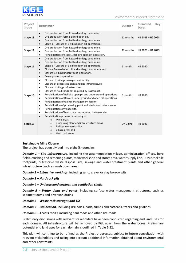
Environmental Impact Statement
2-51 Jervois Base Metal Project
Project
Stage Description Duration
Estimated Key
Dates
Stage 13
• Ore production from Reward underground mine.
• Ore production form Bellbird open pit.
• Ore production from Bellbird underground mine.
• Stage 1 – Closure of Bellbird open pit operations.
12 months H1 2028 – H2 2028
Stage 14 • Ore production from Reward underground mine.
• Ore production from Bellbird underground mine.
• Rehabilitation of Stage 1 Bellbird open pit operation.
12 months H1 2029 – H1 2029
Stage 15
• Ore production from Reward underground mine.
• Ore production from Bellbird underground mine.
• Stage 2 – Closure of Bellbird open pit operations.
• Closure Reward open pit and underground operations.
• Closure Bellbird underground operations.
• Cease process operations.
6 months H1 2030
Stage 16
• Closure of tailings management facility.
• Closure of processing plant and site infrastructure.
• Closure of village infrastructure.
• Closure of haul roads not required by Pastoralist.
• Rehabilitation of Bellbird open pit and underground operations.
• Rehabilitation of Reward underground and open pit operations.
• Rehabilitation of tailings management facility.
• Rehabilitation of processing plant and site infrastructure areas.
• Rehabilitation of village site.
• Rehabilitation of haul roads not required by Pastoralist.
6 months H2 2030
Stage 17
• Rehabilitation process monitoring of: o Mine areas o processing plant and infrastructure areas o Tailings storage facility o Village area; and o Haul road areas.
On Going H1 2031
Sustainable Mine Closure The project has been divided into eight (8) domains:
Domain 1 – Site Infrastructure, including the accommodation village, administration offices, bore fields, crushing and screening plants, main workshop and stores area, water supply line, ROM stockpile footprints, putrescible waste disposal site, sewage and water treatment plants and other general infrastructure (such as wash down area)
Domain 2 – Extractive workings, including sand, gravel or clay borrow pits
Domain 3 – Hard rock pits
Domain 4 – Underground declines and ventilation shafts
Domain 5 – Water dams and ponds, including surface water management structures, such as sediment dams and diversion drains
Domain 6 – Waste rock storages and TSF
Domain 7 – Exploration, including drillholes, pads, sumps and costeans, tracks and gridlines
Domain 8 – Access roads, including haul roads and other site roads
Preliminary discussions with relevant stakeholders have been conducted regarding end land uses for each domain. All infrastructure will be removed by KGL apart from the water bores. Preliminary potential end land uses for each domain is outlined in Table 2-22.
This plan will continue to be refined as the Project progresses, subject to future consultation with relevant stakeholders and taking into account additional information obtained about environmental and other constraints.

Project Overview
SECTION 2 | Project Description 2- 52
Table 2-22 Preliminary Potential End Land Uses for Each Domain
Domain Component Preliminary Potential End Land Uses
Site
Infrastructure
Accommodation
village
Traditional land use and resilient, self-
sustaining native vegetation of local
provenance providing suitable habitat for
fauna. Administration
offices
Airstrip Left for use by landowners.
Borefields Surrounding areas to be available for return to
pastoral use.
Crushing and
screening plant
Traditional land use and resilient, self-
sustaining native vegetation of local
provenance providing suitable habitat for
fauna. Main workshop and
stores area
Sewerage, water
treatment plant
Water supply line
Product stockpile
and ROM stockpile
footprints
Putrescible waste
disposal site
Other general
infrastructure
Extractive
workings
Borrow pits Stabilised modified landform providing
traditional land use and resilient, self-sustaining
native vegetation of local provenance.
Hard rock pits Backfilled pits Stabilised modified landform providing
traditional land use and resilient, self-sustaining
native vegetation of local provenance.
Open pits Pits: open voids.
Abandonment bund: resilient, self-sustaining
native vegetation of local provenance.
Underground
Openings
Decline Portals The portals secured to prevent unauthorised
access by building a hydraulic plug
incorporating NAF waste rock that will allow
the underground workings to flood naturally,
thus reducing the oxidation of exposed
sulphides and the potential for acid
generation.
Resilient, self-sustaining native vegetation of
local provenance.
Portals will either remain within open pit
modified landforms, or in the case of
Rockface be landscaped into a modified
landform.
Service and
Ventilation Shafts
The shafts will be secured to prevent
unauthorised access by building engineered
concrete plugs that will allow the
underground workings to flood naturally.
Resilient, self-sustaining native vegetation of
local provenance.
Water dams
and ponds
Surface water
management
structures such as
sediment dams and
diversion drains
Ephemeral drainage.
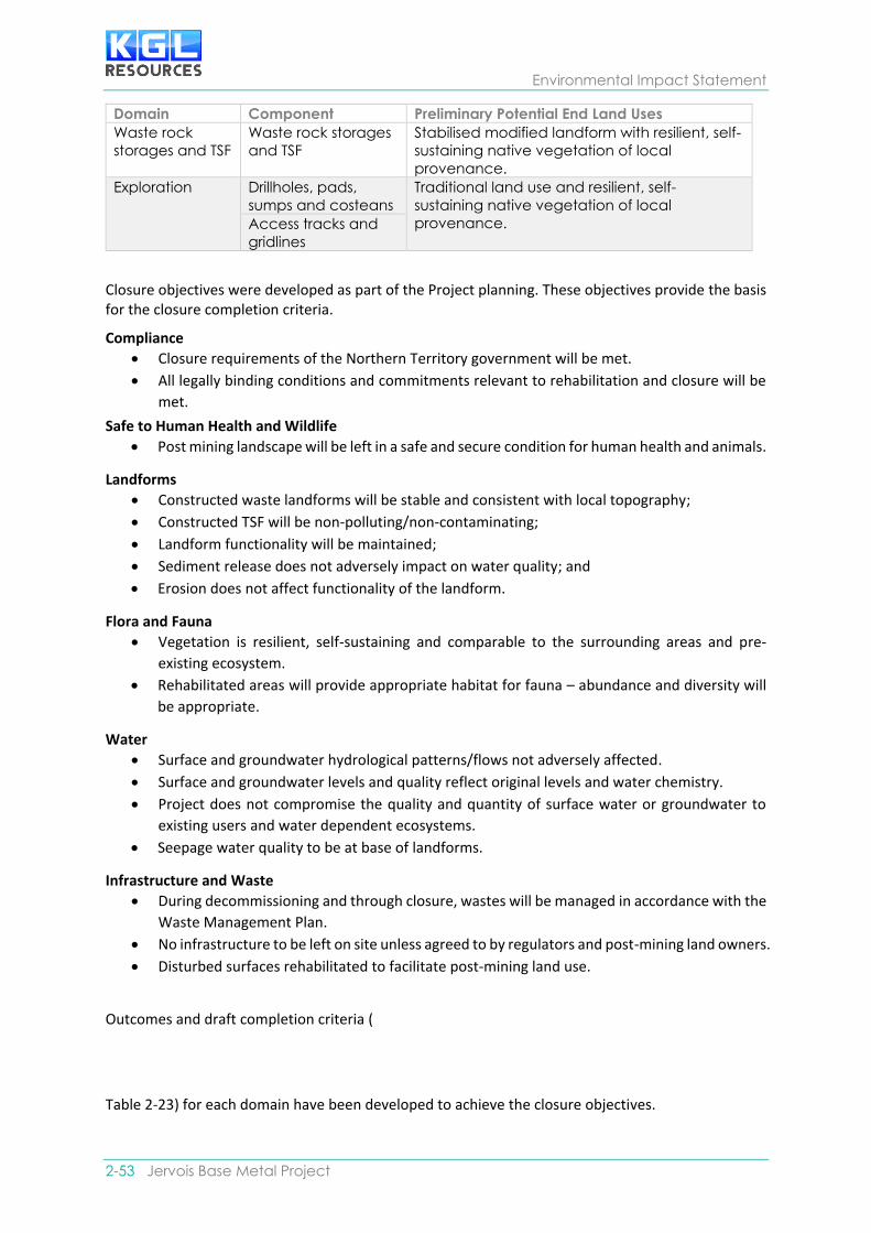
Environmental Impact Statement
2-53 Jervois Base Metal Project
Domain Component Preliminary Potential End Land Uses
Waste rock
storages and TSF
Waste rock storages
and TSF
Stabilised modified landform with resilient, self-
sustaining native vegetation of local
provenance.
Exploration Drillholes, pads,
sumps and costeans
Traditional land use and resilient, self-
sustaining native vegetation of local
provenance. Access tracks and
gridlines
Closure objectives were developed as part of the Project planning. These objectives provide the basis for the closure completion criteria.
Compliance
• Closure requirements of the Northern Territory government will be met.
• All legally binding conditions and commitments relevant to rehabilitation and closure will be
met.
Safe to Human Health and Wildlife
• Post mining landscape will be left in a safe and secure condition for human health and animals.
Landforms
• Constructed waste landforms will be stable and consistent with local topography;
• Constructed TSF will be non-polluting/non-contaminating;
• Landform functionality will be maintained;
• Sediment release does not adversely impact on water quality; and
• Erosion does not affect functionality of the landform.
Flora and Fauna
• Vegetation is resilient, self-sustaining and comparable to the surrounding areas and pre-
existing ecosystem.
• Rehabilitated areas will provide appropriate habitat for fauna – abundance and diversity will
be appropriate.
Water
• Surface and groundwater hydrological patterns/flows not adversely affected.
• Surface and groundwater levels and quality reflect original levels and water chemistry.
• Project does not compromise the quality and quantity of surface water or groundwater to
existing users and water dependent ecosystems.
• Seepage water quality to be at base of landforms.
Infrastructure and Waste
• During decommissioning and through closure, wastes will be managed in accordance with the
Waste Management Plan.
• No infrastructure to be left on site unless agreed to by regulators and post-mining land owners.
• Disturbed surfaces rehabilitated to facilitate post-mining land use.
Outcomes and draft completion criteria (
Table 2-23) for each domain have been developed to achieve the closure objectives.

Project Overview
SECTION 2 | Project Description 2- 54
Table 2-23 Closure Outcomes and Completion Criteria
Domain Outcome Draft Completion Criteria
Site Infrastructure
Accommodation
Village
All infrastructure removed Audit against final MRCP to
confirm accommodation
village or related infrastructure
does not remain on site
Administration Offices All infrastructure removed Audit against final MRCP to
confirm the administration
offices or related infrastructure
does not remain on site
Airstrip All infrastructure required for
function as airstrip to be left
for use by landowner
Audit against final MRCP to
confirm only required airstrip
infrastructure remains on site
Bore fields No adverse change in
ecological condition
Field surveys show no increase
in numbers of feral grazing
animals above baseline
conditions
Bore fields decommissioned
unless required for end land
use or requested and agreed
between KGL and Traditional
Owners and/or pastoralists
Audit against final MRCP to
ensure only bore fields required
remain in use, those not
required are decommissioned
according to relevant Northern
Territory guidelines and
regulations
processing plant All infrastructure removed Audit against final MRCP to
confirm processing plant or
related infrastructure does not
remain on site
Main workshop and
stores area
All infrastructure removed Audit against final MRCP to
confirm no workshop, stores
area or related infrastructure
remains on site
Sewerage, water
treatment plant
All infrastructure removed Audit against final MRCP to
confirm no sewage and water
treatment plant or related
infrastructure remains on site
Water supply line All infrastructure removed Audit against final MRCP to
confirm no water supply line
infrastructure remains on site
Power Station All infrastructure removed Audit against final MRCP to
confirm no power station and
related infrastructure remains
on site
Other general
infrastructure
All infrastructure removed Audit again final MRCP to
confirm no other general
infrastructure remains on site
Extractive Workings
Borrow pits Landscape function and
vegetation is resilient and self-
sustaining and comparable
to surrounding area. Left with
Landscape and vegetation
assessment undertaken and
reported to show function is
resilient, self-sustaining and

Environmental Impact Statement
2-55 Jervois Base Metal Project
Domain Outcome Draft Completion Criteria
no risk of becoming a trap for
people or fauna
comparable to the surrounding
areas
Hard Rock Pits
Backfilled pits Landscape function and
vegetation is resilient, self-
sustaining and comparable
to surrounding area
Landscape and vegetation
assessment undertaken and
reported to show function is
resilient, self-sustaining and
comparable to the surrounding
areas
Open pits Water quality in open pit
voids is suitable and does not
lower surrounding water
quality or impact fauna that
may use them, e.g., birds
Monitoring post closure
demonstrates that pit water
meets applicable criteria. No
creation of long-term mosquito
breeding habitat
No impact on water quantity
or quality available to existing
groundwater users due to pit
inflow
Monitoring post closure of site
bores demonstrates there is no
change from baseline in terms
of quality or quantity and audit
shows that recharge is as per
predictions
No injuries or deaths resulting
from pit stability or ease of
access to pit
Abandonment bund
constructed around the pit
perimeter to restrict
inadvertent access to the pit
void, with the location of the
bund to be determined by a
geotechnical specialist
Pit ramps blocked to prevent
inadvertent access
Geotechnical assessment of pit
at closure demonstrates
stability is acceptable in
accordance with relevant
safety requirements
Portals and Shafts
No impact on water quantity
or quality available to existing
groundwater users due to pit
inflow
Monitoring post closure of site
bores demonstrates there is no
change from baseline in terms
of quality or quantity and audit
shows that recharge is as per
predictions
No injuries or deaths resulting
from stability or ease of
access
The shafts and decline portals will be secured to prevent unauthorised access by building engineered concrete plugs that will allow the underground workings to flood naturally: resilient, self-sustaining native vegetation of local provenance
Water Dams and Ponds
Surface water
management structures
Surface water storage areas
rehabilitated to provide
ephemeral drainage
Surface water assessment
undertaken and report to show
areas function as ephemeral

Project Overview
SECTION 2 | Project Description 2- 56
Domain Outcome Draft Completion Criteria
drainage aligned with
surrounding natural drainage
No creation of long-term
mosquito breeding habitat
All surface water structures
remaining in place are
physically stable and safe to
fauna and humans
Audit against final MRCP to
confirm stability and safety is in
accordance with relevant
standards and requirements
Waste Rock Storages
and TSF
Waste rock storages Waste rock storages are
physically and chemically
stable
Geotechnical assessment
shows that waste rock storage
are physically stable.
Monitoring to demonstrate no
adverse impact to the quality
and quantity of surface or
groundwater caused by waste
rock storages to water-
dependent ecosystems
Tailings Storage Facility Constructed TSF will be
returned to underground and
pit void, or make non-
polluting/non-contaminating
Monitoring to demonstrate no
adverse impact to the quality
and quantity of surface or
groundwater caused by
returned tailings underground
or in pit to water-dependent
ecosystems
Geotechnical and
geochemical assessment
shows that TSF are physically
and geochemically stable and
sustainable if remained on
surface
Exploration
Drillholes, pads, sumps
and costeans
Ecosystem and landscape
function is resilient and self-
sustaining and comparable
to surrounding area and pre-
existing ecosystem
Audit shows all exploration drill
holes rehabilitated in
accordance with relevant
Northern Territory Government
guidelines
Audit shows all costeans and
sumps backfilled or battered
and rehabilitated in
accordance with Northern
Territory Government
guidelines
Access tracks and
gridlines
Ecosystem and landscape
function is resilient and self-
sustaining and comparable
to surrounding area.
Audit shows all access tracks,
grid lines and drill pads
rehabilitated as per Northern
Territory Government
guidelines
Access and haul roads
Access road Access road rehabilitated
unless required for end land
use by Traditional Owners
Audit against final MCRP shows
all access road infrastructure
no longer required is
rehabilitated
Haul roads All haul roads rehabilitated
unless required for end land
Audit against final MCRP shows
all haul road and other site

Environmental Impact Statement
2-57 Jervois Base Metal Project
Domain Outcome Draft Completion Criteria
use by Traditional Owners
and/or Pastoralist
road infrastructure
rehabilitated
Other site roads All other site roads
rehabilitated unless required
for end land use by
Traditional Owners and/or
Pastoralist
Audit against final MCRP shows
all other site road infrastructure
no longer required is
rehabilitated
A monitoring program has been developed as part of the MCRP to investigate the success of rehabilitation and whether completion criteria are being achieved and to identify any additional work required to meet success criteria. Rehabilitation will be monitored during operations and after final rehabilitation has been completed. The need for ongoing monitoring and the frequency of monitoring will be continuously assessed. Monitoring will include:
• Plant establishment, growth, diversity and cover;
• Evidence and type of erosion;
• Water quality including groundwater and surface water;
• Air quality;
• Landform stability including cover system performance;
• Soil quality; and
• Fauna.
Reports on monitoring results and progress towards mine closure criteria will be issued to relevant stakeholders annually.
Alternate Options Rehabilitation of mined and other disturbed landforms will be undertaken progressively, as infrastructure becomes redundant and is decommissioned. Re-establishment of vegetation at disturbed sites will reduce the duration of habitat loss for certain flora and fauna. Progressive rehabilitation will be incorporated into the mine schedule in the detailed planning stage and during operations. Where practicable, disturbed areas and/or areas no longer required for mining will be rehabilitated during operations.
Pits will be mined using conventional open pit methods. The extent to which the pits will be backfilled and progressively rehabilitated will be dependent upon the detailed mining schedule and the economic viability of backfilling, such as haulage distance for backfilling.
The PAF waste material mined from underground will be disposed of preferentially in underground voids and used as backfill whenever possible rather than being disposed of on the surface to reduce the footprint of the site. In pit dumping will be the preferred option for the PAF waste mined during early stage development at Reward and Bellbird.
Tailings will be paste backfilled into underground workings preferentially to reduce the inventory of tailings requiring surface management. Preferably on closure, tailings will be returned to the pit void. Detailed studies will be carried out in the detailed planning stage to investigate the feasibility of the preferred TSF rehabilitation option.
An alternative option for TSF rehabilitation will be to install a basic store and release cover system to isolate the tailings from the environment as suggested in Appendix C-12 Tailings Storage Facility Design Report. This will comprise the following nominal design concepts:
• A low permeability layer over the surface of the tailings to reduce water movement into and out of the tailings.
• A store and release layer to provide water storage after storms for later us by vegetation or removal by evaporation.
• A topsoil layer will be integrated into the surface of the store and release layer for vegetation growth.

Project Overview
SECTION 2 | Project Description 2- 58
• Thickness of layers will be determined based on material selection and climatic conditions.
Conceptual Mine Rehabilitation and Closure Plan The conceptual MRCP include the following:
• Draft closure criteria, future land tenure and land-use arrangements;
• Draft protocols for securing a safe and stable mine-site;
• Proposed staging and timing of rehabilitation and closure;
• Removal of plant, equipment, infrastructure, water storages, and methods proposed for
stabilisation of affected areas;
• Proposed methods for topsoil management and soil profile reconstruction, with
demonstration of their effectiveness for rehabilitating disturbed areas;
• Revegetation strategies for disturbed sites;
• Measures to ensure soil stabilisation against erosion to a level similar to comparable
landforms in surrounding undisturbed areas;
• Contingencies to make landforms and mine components secure and non-polluting;
• Proposed final topographic and drainage morphology, including design concepts and
methods to be used; and
• Proposed funding and management arrangements, including responsibilities for post –
closure.
Post Closure Risk Assessment A post closure risk assessment has been completed as part of the Project risk assessment. Risks identified include:
• Residual liability for site rehabilitation or maintenance for the community and future
generations due if the site is not rehabilitated and infrastructure is not removed;
• Site not appropriately rehabilitated after closure;
• Final waste rock dumps at closure not appropriately designed resulting in a reduction in
visual amenity;
• Unexpected loss of financial support or unexpected population decline if the mine closure
concept and timing are not communicated/understood in the local community;
• Premature closure due to commodity price decrease, weather issues, technical failures,
bankruptcy, etc;
• Long term contamination of land;
• Bore fields not appropriately decommissioned;
• Surface water structures not physically stable;
• Waste rock dumps not physically or chemically stable;
• Inadequate rehabilitation of exploration sites; and
• Natural Disaster.
Details on the post closure risk assessment is outlined in the MRCP.
2.4. Approvals & Conditions The EIS Introduction in Section 1 provides an overview of the legislation and associated approvals and conditions which relate to the Project. A detailed summary of the applicable legislation is located in Appendix C-13 Relevant Legislation.


