53
Project Proposal and Feasibility Study Team 5 – Com 1 Com All Joe Gluvers, Justin Slocum, Josh Velthouse Calvin College Engineering 339 – Senior Design Project Monday, December 10, 2007

Project Proposal and Feasibility Study
Team 5 – Com 1 Com All
Joe Gluvers, Justin Slocum, Josh Velthouse
Calvin College
Engineering 339 – Senior Design Project
Monday, December 10, 2007

2
Table of Contents Table of Figures .............................................................................................................................. 5 Table of Tables ............................................................................................................................... 5 1.0 Introduction ............................................................................................................................... 6
1.1 Senior Design ........................................................................................................................ 6 1.2 Team Description .................................................................................................................. 6
1.2.1 Joe Gluvers .................................................................................................................... 6 1.2.2 Justin Slocum ................................................................................................................. 7 1.2.3 Josh Velthouse ............................................................................................................... 7
1.3 Our Project ............................................................................................................................ 7 1.4 This Document ...................................................................................................................... 7
2.0 Problem Statement .................................................................................................................... 7 3.0 Project Objectives ..................................................................................................................... 8
3.1 Affordability ......................................................................................................................... 8 3.2 Simplicity (Transparency) .................................................................................................... 8 3.3 Insensitive to AC Power Fluctuations................................................................................... 8 3.4 Easily Manufacturable .......................................................................................................... 8
4.0 Christian Perspective ................................................................................................................ 9 4.1 Product’s Purpose ................................................................................................................. 9 4.2 Specific Design Norms ......................................................................................................... 9
4.2.1 Transparency ................................................................................................................. 9 4.2.2 Integrity ........................................................................................................................ 10
4.2.3 Stewardship .................................................................................................................. 10 4.2.4 Cultural Appropriateness............................................................................................. 10 4.2.5 Trust ............................................................................................................................. 11
4.2.6 Caring .......................................................................................................................... 11
5.0 Alternative Solutions .............................................................................................................. 11 5.1 “Wireless” Wired System ................................................................................................... 11 5.2 Wired System ...................................................................................................................... 12
5.3 RF Wireless System ............................................................................................................ 12 6.0 Patent Concerns ...................................................................................................................... 13
6.1 Wireless Patents .................................................................................................................. 13 6.2 Component Patents ............................................................................................................. 13
7.0 Market Study ........................................................................................................................... 13 7.1 Overview of Options ........................................................................................................... 14
7.1.1 Home Power Circuit Intercom Systems ....................................................................... 14 7.1.2 High-end Wired Intercom Systems............................................................................... 15 7.1.3 Wireless Intercom Systems ........................................................................................... 15
7.2 TCOM’s Place in the Market ................................................................................................. 16 7.3 Sales Prospects .................................................................................................................... 16
8.0 Detailed Requirements ............................................................................................................ 17 8.1 Prototype Requirements ...................................................................................................... 17
8.1.1 Functionality ................................................................................................................ 17 8.1.2 Power ........................................................................................................................... 20 8.1.3 Size ............................................................................................................................... 21
8.1.4 Environmental .............................................................................................................. 21
3
8.1.5 Cost .............................................................................................................................. 21
8.2 Production Requirements .................................................................................................... 22 8.2.1 Functionality ................................................................................................................ 22 8.2.2 Power ........................................................................................................................... 22
8.2.3 Packaging .................................................................................................................... 22 8.2.4 Environmental .............................................................................................................. 23 8.2.5 Cost .............................................................................................................................. 23 8.2.6 FCC Compliance ......................................................................................................... 23
9.0 Preliminary Design ................................................................................................................. 24
9.1 System Design .................................................................................................................... 24 9.1.1 Modular Unit Network Implementation ....................................................................... 24 9.1.2 Modular System Design ............................................................................................... 24
9.2 Hardware Design ................................................................................................................ 27
9.2.1 Preliminary Block Diagram ......................................................................................... 27 9.2.2 Wireless Transmission Technology.............................................................................. 27
9.2.5 LCD Display ................................................................................................................ 31 9.2.6 User Keypad and Scroll Wheel Control....................................................................... 32
9.2.7 Real Time Clock ........................................................................................................... 32 9.2.8 Microphone .................................................................................................................. 32 9.2.9 Speaker ......................................................................................................................... 33
9.2.10 Antenna ...................................................................................................................... 33 9.2.11 Additional Analog Circuitry ...................................................................................... 34
9.2.13 Circuit board layout ................................................................................................... 34 9.2.14 Product packaging ..................................................................................................... 34 9.2.15 Current Block Diagram ............................................................................................. 35
10.3 Software Design ................................................................................................................ 35
10.3.1 Auto Setup .................................................................................................................. 36 10.3.2 Network ...................................................................................................................... 36 10.3.3 Update ........................................................................................................................ 37
10.3.4 Top Menu ................................................................................................................... 37 10.3.5 Call and Receive ........................................................................................................ 37
10.3.6 Talk and Listen ........................................................................................................... 37 10.3.7 Alarm and Clock Set .................................................................................................. 37
10.3.8 Watchdog ................................................................................................................... 38 10.4 Network Protocol .............................................................................................................. 38
10.4.1 Call Request and Monitor .......................................................................................... 38 10.4.1 Talk Start, Talk End, and Call End ............................................................................ 38 10.4.2 New Module Request and New Module Return ......................................................... 39
10.4.3 Update ........................................................................................................................ 39 11.0 Feasibility study .................................................................................................................... 39
11.1 Audio Quality Study ......................................................................................................... 39 11.1.1 Bit Depth .................................................................................................................... 39 11.1.2 Frequency Range ....................................................................................................... 40 11.1.3 Noise .......................................................................................................................... 40 11.1.4 Audio Quality of Design............................................................................................. 41
11.2 Data Transfer Analysis ..................................................................................................... 41

4
11.2.1 Transceiver ................................................................................................................ 41
11.2.2 Codec ......................................................................................................................... 41 11.2.3 Microprocessor .......................................................................................................... 42
11.3 Power Consumption Analysis ........................................................................................... 42
11.4 Economic analysis ............................................................................................................ 42 11.4.1 Parts List and Bill of Material ................................................................................... 43 11.4.2 Manufacturing Costs .................................................................................................. 43
12.0 Test Plans .............................................................................................................................. 43 12.1 Prototype Testing Method................................................................................................. 44
12.1.1 Audio Quality ............................................................................................................. 44 12.1.2 Data Transmission ..................................................................................................... 44 12.1.3 Transmission of Audio ............................................................................................... 44 12.1.4 Networking ................................................................................................................. 44
12.1.5 LCD Control .............................................................................................................. 44 12.1.6 Clock and Alarms ....................................................................................................... 44
12.1.7 Power Usage .............................................................................................................. 45 12.2 Final Test Method ............................................................................................................. 45
12.2.1 User Functionality Testing ........................................................................................ 45 12.2.2 System Endurance Testing ......................................................................................... 45 12.2.3 Range Testing............................................................................................................. 45
13.0 Task breakdown and time schedule ...................................................................................... 45 14.0 Full scale production plan (further updates to come) ........................................................... 46
14.1 Large Scale Bill of Materials ............................................................................................ 46 14.2 Parts Provider .................................................................................................................... 46 14.3 Product Assembler ............................................................................................................ 47
14.4 Compliance Testing .......................................................................................................... 47
Appendices .................................................................................................................................... 48 Appendix A: Expanded Task List and Schedule ...................................................................... 48 Appendix B: Market Study ....................................................................................................... 50
Appendix C: Data Transfer Analysis ........................................................................................ 51 Appendix D: Production Cost ................................................................................................... 53
5
Table of Figures Figure 1: Team Photo...................................................................................................................... 6 Figure 2 - GE/Jasco TL97600 ....................................................................................................... 15 Figure 3 - GE SmartCom Module ................................................................................................. 15 Figure 4 - Westinghouse WHI-4CUPG ........................................................................................ 16 Figure 5 - System Level Functionality.......................................................................................... 25
Figure 6 - Initial Design Concept.................................................................................................. 26 Figure 7 - Initial Hardware Block Diagram .................................................................................. 27 Figure 8 - Designed Usage of Set Frequency Channels ............................................................... 29 Figure 9 - Current Hardware Block Diagram ............................................................................... 35 Figure 10 - Software Block Diagram ............................................................................................ 36
Figure 11 - Signal Approximation with Bit Resolution (zone.ni.com)......................................... 40 Figure 12 - Task Breakdown and Time Schedule ......................................................................... 46
Table of Tables Table 1 - Available Intercom Examples ....................................................................................... 14 Table 2 - Decision Matrix for Wireless Protocol .......................................................................... 28
Table 3 - Decision Matrix for Transceiver Selection.................................................................... 30 Table 4 - Microcontroller Decision Matrix ................................................................................... 30
Table 5 - LCD Decision Matrix .................................................................................................... 32 Table 6 - Mirophone Decision Matrix .......................................................................................... 33 Table 7 – Network Protocol Instruction Set ................................................................................. 38
Table 8 - Component Power Requirements .................................................................................. 42 Table 9 - Cost For Purchased and Needed Parts ........................................................................... 43

6
1.0 Introduction
This section will introduce the reader to the context in which this project will be completed
including: the class, the team, the project, and what will be found in the remainder of this report.
1.1 Senior Design
Calvin College is a small liberal arts college in Grand Rapids, MI which offers an Accreditation
Board for Engineering and Technology (ABET) accredited engineering degree in chemical, civil,
electrical, and mechanical concentrations. As the core capstone of this major Engineering 339/340 Senior
Design requires students to form a team to research and design a solution to a problem or fill a need.
1.2 Team Description
Com 1 Com All is a design team made up of three senior electrical engineers: Joe Gluvers, Justin
Slocum and Josh Velthouse. Members of the team can be seen below in Figure 1.
Figure 1: Team Photo
1.2.1 Joe Gluvers
Joe is a senior engineer in the electrical concentration, and has a broad taste within the field of
electrical engineering. This summer he worked for Twisthink LLC in Holland, MI as an intern
7
and developed his skills in test development and reporting. Joe is originally from Sacramento,
CA where he attended Rocklin High School before coming to Calvin College. He is also a four
year varsity swimmer for Calvin and a team captain this year. He recently celebrated his first
anniversary and will be working mostly on the overall visual design and human interface of the
device.
1.2.2 Justin Slocum
Justin is focused on hardware design and board layouts for digital and analog electrical systems;
he is working on an engineering degree of electrical concentration and a math minor. While
working at Dorner Works Imbedded Systems Engineering in Grand Rapids, MI this summer and
through this year Justin worked on development and testing of imbedded hardware systems as
well as gained experience in reverse engineering. He hails from suburban Detroit where he
attended Oscar A. Carlson High School before coming to Calvin College. When not engineering,
Justin is also a member of the Calvin College Capella. He will be working on the board layout,
RF communication, and other various support tasks.
1.2.3 Josh Velthouse
Josh is a programming focused electrical engineer and will receive an additional math minor. He
worked as an intern at Gentex Corporation in Holland, MI where he gained valuable experience
in a manufacturing environment. Josh is originally from Holland and attended Holland Christian
High School prior to attending Calvin College. He also enjoys singing, reading, and creating. It
is likely he will be working on much of the programming and related functionality of the design.
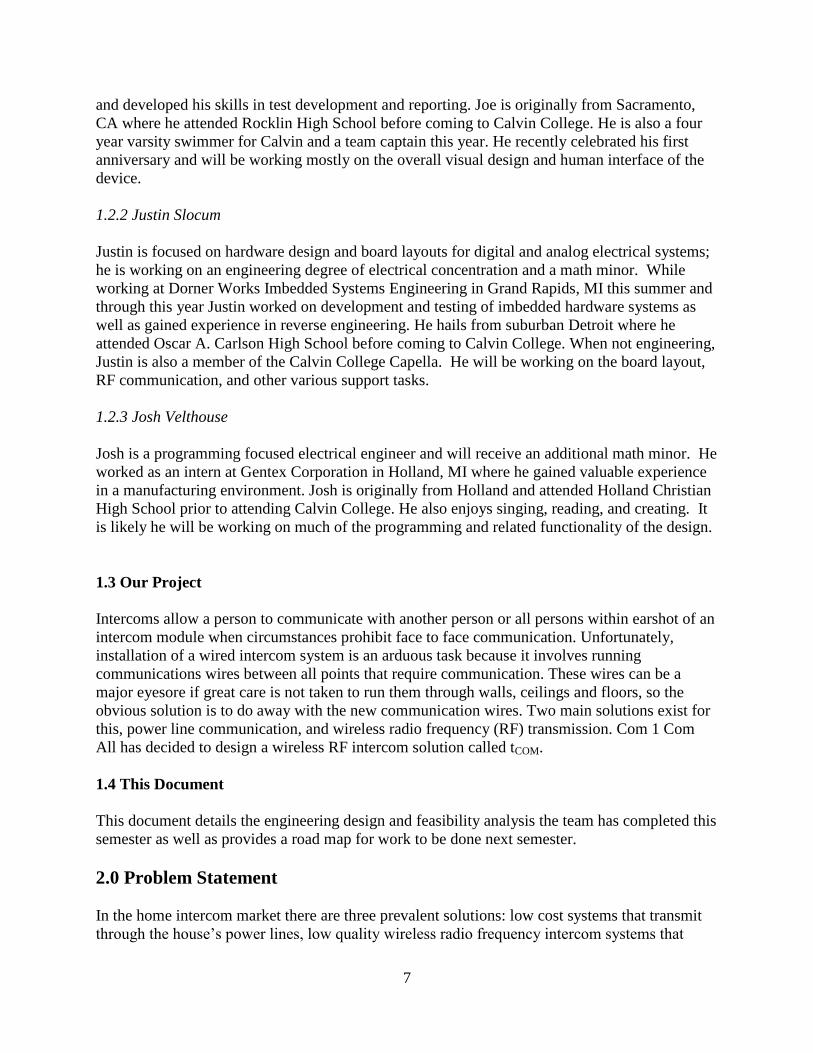
1.3 Our Project
Intercoms allow a person to communicate with another person or all persons within earshot of an
intercom module when circumstances prohibit face to face communication. Unfortunately,
installation of a wired intercom system is an arduous task because it involves running
communications wires between all points that require communication. These wires can be a
major eyesore if great care is not taken to run them through walls, ceilings and floors, so the
obvious solution is to do away with the new communication wires. Two main solutions exist for
this, power line communication, and wireless radio frequency (RF) transmission. Com 1 Com
All has decided to design a wireless RF intercom solution called tCOM.
1.4 This Document
This document details the engineering design and feasibility analysis the team has completed this
semester as well as provides a road map for work to be done next semester.
2.0 Problem Statement
In the home intercom market there are three prevalent solutions: low cost systems that transmit
through the house’s power lines, low quality wireless radio frequency intercom systems that
8
offer little more than simple communication similar to walkie-talkies, and advanced wired
intercoms that mesh with home security systems, offering video communication and
surveillance, home control features, and costing upwards of a thousand dollars per module. Our
goal is to provide reliable and feature rich wireless communication to both do-it-yourself home
improvers and new home builders to fit in the niche between the represented extremes.
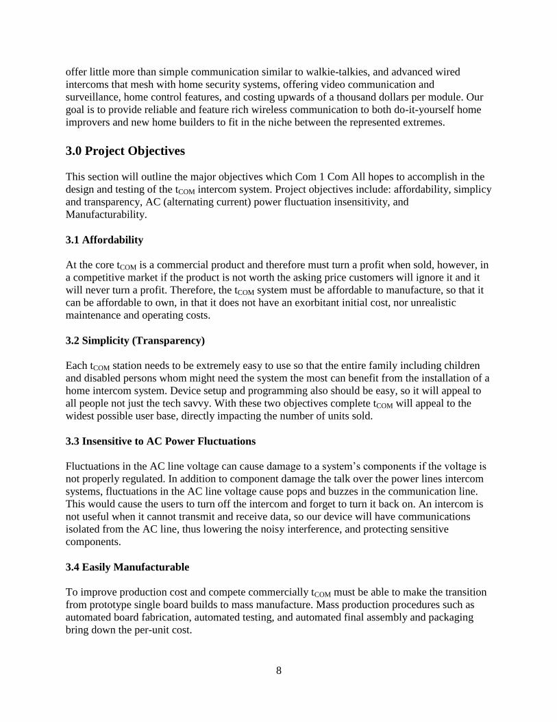
3.0 Project Objectives
This section will outline the major objectives which Com 1 Com All hopes to accomplish in the
design and testing of the tCOM intercom system. Project objectives include: affordability, simplicy
and transparency, AC (alternating current) power fluctuation insensitivity, and
Manufacturability.
3.1 Affordability
At the core tCOM is a commercial product and therefore must turn a profit when sold, however, in
a competitive market if the product is not worth the asking price customers will ignore it and it
will never turn a profit. Therefore, the tCOM system must be affordable to manufacture, so that it
can be affordable to own, in that it does not have an exorbitant initial cost, nor unrealistic
maintenance and operating costs.
3.2 Simplicity (Transparency)
Each tCOM station needs to be extremely easy to use so that the entire family including children
and disabled persons whom might need the system the most can benefit from the installation of a
home intercom system. Device setup and programming also should be easy, so it will appeal to
all people not just the tech savvy. With these two objectives complete tCOM will appeal to the
widest possible user base, directly impacting the number of units sold.
3.3 Insensitive to AC Power Fluctuations
Fluctuations in the AC line voltage can cause damage to a system’s components if the voltage is
not properly regulated. In addition to component damage the talk over the power lines intercom
systems, fluctuations in the AC line voltage cause pops and buzzes in the communication line.
This would cause the users to turn off the intercom and forget to turn it back on. An intercom is
not useful when it cannot transmit and receive data, so our device will have communications
isolated from the AC line, thus lowering the noisy interference, and protecting sensitive
components.
3.4 Easily Manufacturable
To improve production cost and compete commercially tCOM must be able to make the transition
from prototype single board builds to mass manufacture. Mass production procedures such as
automated board fabrication, automated testing, and automated final assembly and packaging
bring down the per-unit cost.

9
4.0 Christian Perspective
Since we are all Christian engineers, our faith undoubtedly will have a significant impact on both
our final system design in addition to how we go about our design process. Although this project
at first glance may not seem to have specific applications for “Christian life” or “outreach”, the
final product would impact everyday living which is itself an offering to God. Also, community
and relationships are central to human life for people of all religious perspectives and an
intercom system is one way to further enable communication between friends, families, and
coworkers. What could be seen as a somewhat insignificant gadget could have significant
impact on how people live with each other in worship to their creator.
4.1 Product’s Purpose
The overall aim of the tCOM is to enable communication within a home or business. This is done
by enabling verbal contact between areas/rooms which were previously physically separated by
walls or physical distance. Although not a necessity, having an intercom system offers a simple
way to save time and physical energy communicating between different locations in a building.
In addition, the intercom system would also provide added safety to the home environment.
Extra features like a “Listen Mode” (baby monitor type feature) would allow parents to monitor
young children who are sleeping or playing in another room. We see our intercom system as a
very useful addition for many homes and businesses.
4.2 Specific Design Norms
Design norms are a collection of ethical principles which engineers or other professionals can
use as a framework to base the design of a product or process. They can be used effectively to
remind the engineer what is needed by the end user and thus help to provide a better serve their
client. In addition to affecting the end design, many of these design norms also apply directly to
the design process itself and how the engineer carries out their work. Throughout our design
process, we have and will continue to use design norms as a way of guiding choices for tCOM’s
final system design. These will be explained in the context of our project in the following
sections.
4.2.1 Transparency
It is essential for the intercom system to be intuitive for the user and easy to program and use. If
the customer has difficulty learning how to use the system, it will be little more than a dust
collector that will not at all be useful. Additionally, young children may potentially have to use
the intercom in the home setting. This means that small children must be able to easily learn and
use the intercom as well as adults.
This will affect our design most noticeably in the area of the user interface. We want to provide
the robust system features (“Com 1/Com All”, module naming, automatic network setup and
upkeep, hot button communication, synchronized system clock, alarms) using only as many
buttons as is absolutely necessary. Extra buttons would cause a cluttered and confusing exterior
for the user.

10
4.2.2 Integrity
In addition to providing a product that is easy to use, we feel it is also extremely important that
we provide the customer with a product that works well and respects their privacy concerns
when using the intercom. Because of this the audio quality delivered to the end user should be of
sufficient both in possible volume and audio quality with reduction of electrical noise. Other
systems became functionally useless due to the problem of noise on the signal. So, it will be of
key importance in the final integrity of our product. Also, the system should provide reliable
functionality for the end user, secure communication kept within the home network, and not
become quickly obsolete due to other technology changes. All of these are expectations of
potential customers that must be met if our product is to serve them well.
Integrity also covers the area of how we work on the project and develop our designs. We are
called to honesty in the amount and source of our ideas and eventual designs and should always
give credit to those who have given us their valuable input.
4.2.3 Stewardship
Finally, we believe that it is extremely important to provide a high quality final product while
making good use of our and the consumers resources. Solid technical functionality and low cost
to the consumer should take precedent over flashy features that would drive up the final system
cost. Many of the existing products on the market have a large financial cost for an intercom
with robust functionality and wireless or dedicated wired audio transmission. It is our hope to be
able to dramatically lower the final cost of our intercom while still providing robust features the
consumer will find desirable. This will make it a more easily accessible product for those who
may have ignored the product due to the high prices in the past.
4.2.4 Cultural Appropriateness
The fact that tCOM may be used in commercial/business environments in addition to the
residential environment adds another layer of complexity to the design tasks. Usage in a small
business would be very different from in a home and thus requires a slightly different or more
flexible design to account for these differences. For example, a monitor or listening mode may
be a critical feature for a couple with a new baby but would probably be looked upon negatively
in the work environment. As a result, our design must take into account the fact that the user
may wish to prevent other intercoms from listening in on them by making some sort of blocking
feature available.
Also, the possibility of this product being used in other countries must be considered in the final
production design. This may not change the technical functionality offered by the tCOM, but it
would have a major impact on how the product would be packaged and marketed in those
countries. It would be extremely short sighted to think that someone who only spoke or read
French for example would be quick to buy a product which only used English. Exterior
packaging should have varying markings based on the native language of the country in which it
is being sold. In addition, the interactive menus displayed should have the option of changing
the language to the user’s language of choice. Finally, each country will most likely have a
11
slightly different view of the product in the marketplace and would require varying strategies in
marketing and distribution.
4.2.5 Trust
The consumer being able to find the tCOM as a reliable and useful product will be critical to it
finding a permanent place within the intercom market. In the past, many consumers were
completely disappointed with the functionality of inexpensive systems which claimed wireless
capability while the functionality depended completely on the wires within the building. Some
of these consumers may have had their thoughts of purchasing an intercom greatly reduced and
the tCOM will have to work at rebuilding the sense of trust in these products. As designers, we
must be open and honest about the capabilities and functionality of the final design and portray it
as such to the customer. If this is not done, the customer will feel betrayed and would be
unlikely to look to our products in the future because of such a deception.
4.2.6 Caring
All things considered, we want to design this product in such a way that we serve the customer’s
needs by creating a product that will improve their everyday life. Every aspect of the design
should look to improve the way it serves the end user’s immediate community. Caring for the
customer encompasses all of the other design norms and is at the core of the design and design
process.
5.0 Alternative Solutions
In order to deliver basic intercom functionality, the designer must, at minimum, be able to
transmit the audio from one intercom to another. There are three basic means of audio
transmission used in intercom systems: sending the signal through the building AC power lines,
additional wires between the intercom stations, or an RF (radio frequency) connection between
intercom stations. These each have their own strengths and weaknesses that should be
considered when implementing an intercom system or any other audio link.
5.1 “Wireless” Wired System
In this implementation, the audio signal is sent over the building’s AC power lines by impressing
a low frequency, frequency modulated carrier signal which carries the audio. The carrier signal
also must have a small amplitude so it will not significantly change the existing 120 VAC power
signal. This is a functionally low cost option since the transmission medium is already
implemented within the building. All the intercom system would have to do is to create the
modulated carrier and demodulate and the receiver side to recover the original audio. The
savings on additional wiring or RF connections would be significant thus dramatically reducing
the cost of the intercom system.
Unfortunately, some fairly serious problems for audio transfer come with the power lines within
your home. IEEE (Institute of Electrical and Electronics Engineers, Inc.) member Luis Montoya,
in an article about power line communication protocols, points to several problems with

12
implementing communication over power lines. First, power lines were only meant to be used
for transmission of power at a frequency of at most 400 Hz. Additionally, it is difficult to
produce dependable results since power lines are extremely “electronically contaminated” and
signal attenuation is high at the frequencies used. The results of these problems could be heard
in many people who have used these systems. Many complained of noise demodulated from the
wiring when audio was not being transmitted causing unacceptable audible noise being produced
at the intercom speaker. Others also criticized these systems for having unreliable behavior in
which configurations which worked one day would not on another. Finally, these systems can
only transmit data between intercoms which are connected to the same physical circuit within the
house. Otherwise the receiving intercom wouldn’t even see the audio signal being sent making
the pair useless.
5.2 Wired System
These audio transmission systems use additional dedicated wiring to transmit audio and other
data between a number of intercoms. Twisted pair, coaxial, and Ethernet wires are the most
commonly used for intercom systems. Ethernet is more prevalent among the newest systems.
After the initial cost of implementing all the wiring and setup within the home, these systems can
provide extremely fast data transmission with very few concerns for noise tainting the audio
signal. Because of the additional bandwidth, these systems have much more flexibility to add
additional features in addition to the basic intercom functionality. Many include the option of
inputting and making available audio from another device which could then be listened to on any
of the intercom systems. The increased bandwidth is often dedicated towards video transmission
as well in intercoms implemented as part of a security system.
Cost is the obvious drawback for choosing a dedicated wiring system. As well as the installation
and materials cost for the wiring, there is also the additional cost of implementing a high speed
transmission protocol like Ethernet or otherwise. The task of determining where all of these
signals need to be sent as well sending these large amounts of data is extremely daunting. If
done well though, improvements in system quality would be obvious.
5.3 RF Wireless System
RF or true wireless systems would implement the audio transmission through the means of RF
communication between a transmitter and receiver. In RF communication a base frequency is
selected and that signal is then modulated to include the data that is to be transmitted. How this
is done varies based on the given RF protocol being used. Wireless data transmission is
desirable first of all because it is wireless and would require no installation of additional wires
jus the like “wireless” wired systems. Unlike those systems though, RF intercoms would not be
dependent on a physical system and less likely to have data corrupted by noise.
There are of course drawbacks to the wireless implementation. While there isn’t a physical wire
which would encounter noise on, additional RF signals may be present at the frequency of choice
making it difficult or impossible to transmit the data signals. Bandwidth is also significantly
reduced by going to a wireless connection. Additionally, RF communication is also contingent
upon the receiver being within the physical range of the transmitter. The signal loses power as it
13
travels further from the transmitter and becomes harder for the receiver to successfully receive
the signal. Range is a function of the transmitter output power, receiver sensitivity, and any
signal gain on the antennas used. So, range of a given system can be improved by using a more
powerful antenna. If the two RF intercoms are in range and are not encountering significant
signal on the frequency, a wireless connection should be able to provide effective and
dependable data transmission.
6.0 Patent Concerns
All projects must keep patent infringement and opportunities in mind. With wireless technology
at the forefront of today’s market, there are many patents to be aware of and look over. Patents
are also a source of information and ideas to help projects get on the right track.
6.1 Wireless Patents
There were two wireless intercom patents of interest found regarding tCOM’s design. The first
patent, US 7,103,392 B2, describes a wireless microphone of the sort that might be used in a
restaurant. It mentions other units which include a headset model and a unit with a remote
switch. This patent references patents as late as 1969. No detailed circuitry is provided since the
patent is primarily for the housing. Because the circuitry needed for the design is patented over
20 years before the patents 2002 date, there was no infringement for the design. Likewise
tCOM’s design will incorporate only circuitry such as filters that no longer are covered by
patents.
The second patent describes a wireless hub for attaching multiple wired intercoms to a wireless
headset device. This patent shows a fairly complicated analog circuit that is used to implement
the wireless transmission. Because tCOM’s design does not use extensive analog circuitry, there
is no real opportunity for patenting. No patents were found that patented an arrangement of
patented IC’s.
6.2 Component Patents
While most of the components in tCOM’s design are integrated circuits available for purchase,
there was no manufacture that sold scroll wheels like the ones used in mice. It is possible that
each mouse manufacturer has their own patents for individual use or that some unknown
manufacturer is providing them behind the scenes. More research and inquiry will be needed to
determine whether or not its incorporation will infringe on patent holdings.
7.0 Market Study
Prior to the development of our product, thorough knowledge of the existing intercom market
was necessary. This information would be used to help determine desired features, final product
target cost, technology usage, and marketing strategies. An adequate sampling of the products
currently available were compiled and compared to determine the market status. In addition to
product offerings, data was also collected on annual home construction in the United States.
14
This along with general commercial sales would make up the majority of possible sales for the
tCOM.
7.1 Overview of Options
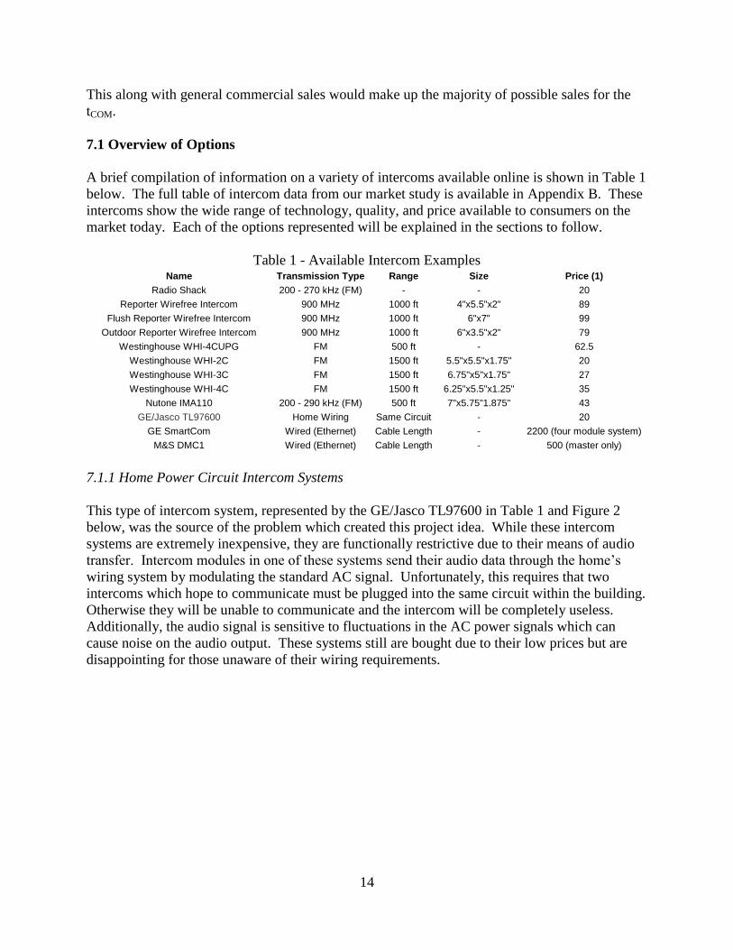
A brief compilation of information on a variety of intercoms available online is shown in Table 1
below. The full table of intercom data from our market study is available in Appendix B. These
intercoms show the wide range of technology, quality, and price available to consumers on the
market today. Each of the options represented will be explained in the sections to follow.
Table 1 - Available Intercom Examples Name Transmission Type Range Size Price (1)
Radio Shack 200 - 270 kHz (FM) - - 20
Reporter Wirefree Intercom 900 MHz 1000 ft 4"x5.5"x2" 89
Flush Reporter Wirefree Intercom 900 MHz 1000 ft 6"x7" 99
Outdoor Reporter Wirefree Intercom 900 MHz 1000 ft 6"x3.5"x2" 79
Westinghouse WHI-4CUPG FM 500 ft - 62.5
Westinghouse WHI-2C FM 1500 ft 5.5"x5.5"x1.75" 20
Westinghouse WHI-3C FM 1500 ft 6.75"x5"x1.75" 27
Westinghouse WHI-4C FM 1500 ft 6.25"x5.5"x1.25" 35
Nutone IMA110 200 - 290 kHz (FM) 500 ft 7"x5.75"1.875" 43
GE/Jasco TL97600 Home Wiring Same Circuit - 20
GE SmartCom Wired (Ethernet) Cable Length - 2200 (four module system)
M&S DMC1 Wired (Ethernet) Cable Length - 500 (master only)
7.1.1 Home Power Circuit Intercom Systems
This type of intercom system, represented by the GE/Jasco TL97600 in Table 1 and Figure 2
below, was the source of the problem which created this project idea. While these intercom
systems are extremely inexpensive, they are functionally restrictive due to their means of audio
transfer. Intercom modules in one of these systems send their audio data through the home’s
wiring system by modulating the standard AC signal. Unfortunately, this requires that two
intercoms which hope to communicate must be plugged into the same circuit within the building.
Otherwise they will be unable to communicate and the intercom will be completely useless.
Additionally, the audio signal is sensitive to fluctuations in the AC power signals which can
cause noise on the audio output. These systems still are bought due to their low prices but are
disappointing for those unaware of their wiring requirements.

15
Figure 2 - GE/Jasco TL97600
7.1.2 High-end Wired Intercom Systems
Another type of wired intercom system does not use the building’s power circuits but additional
wires connecting each of the intercom modules. The GE SmartCom and M&S DMC1 are two
examples of this type of system. GE’s SmartCom module is shown in Figure 3 below. These
intercoms provide much greater reliability in data transfer and include additional features like
home audio distribution from traditional audio devices (i.e. cd players, radios, etc). Along with
the superior functionality and features of these systems comes the overwhelming cost of
implementing them in a home or office. In addition to at least a hundred dollars for each module
and more for master or hub modules, there is the additional material and installation cost for
wiring these systems. There are extremely impractical for existing homes but are a viable option
for new construction or renovation projects.
Figure 3 - GE SmartCom Module
7.1.3 Wireless Intercom Systems

16
The remaining intercoms, those listed first in Table 1, represent systems technically similar to
the proposed tCOM. All of these use RF data transmission to send audio between intercoms
modules. All of the systems we found made use of transmission on either the 200 kHz or 900
MHz frequency ranges. This does not seem to be the only indicator of final system cost even
though the 900 MHz systems are the most expensive systems listed. Additionally the number of
channels available for communication seems to have a direct relationship with the intercom cost.
The Westinghouse intercoms show this as each intercom increases in cost due to the addition of
another channel for communication between intercoms. The most expensive version, the WHI-
4CUPG shown in Figure 4 below, includes five channels the user can set for a module’s
communication. Two intercoms hoping to communicate must be placed on the same channel for
transmission to take place. Additional channels provide flexibility for the user but also force the
modules to be manually placed into the correct channel to communicate with a specific module.
Westinghouse’s least expensive model provides only two channels for communication. None of
these systems provided additional features available on the higher end wired systems like a
graphical interface to provide clock, alarms, or other information to the user.
Figure 4 - Westinghouse WHI-4CUPG
7.2 TCOM’s Place in the Market
Due to tCOM proposed RF transmission, we believe the tCOM will fit into the market as a mid-
priced but fully featured wireless intercom system. The presence of its LCD screen will allow it
to offer additional features not offered on most wireless intercom systems. In addition, the
automatic frequency or channel setup for talking modules will make the system much simpler for
the user. The tCOM will be more expensive than the cheaper intercom systems but should provide
superior functionality to even those systems more expensive than our projected selling costs.
Because of this, it should be a successful product within the existing intercom market.
7.3 Sales Prospects
While data on yearly sales of comparable intercom systems seem to be relatively difficult to
procure, there are still other methods to determine a possible sales market for the tCOM. Our
device will be most useful in the home market and to a lesser extent the smaller office
environment. Because of the tCOM’s ability to be wall mounted or even placed into a wall, an
17
excellent target market would be for new home construction. According to the National
Association of Home Builders (NAHB), there were just over 1.8 million new homes started in
2006. Some percentage of these, assumedly the more expensive homes, probably included
intercom/home audio systems comparable to the GE SmartCom. The tCOM would provide a low
cost alternative, both in system and installation cost, compared to expensive wired systems
which could be offered to new home construction companies and contractors. Additionally, the
lower system cost would make it a more feasible option for less expensive homes. Making a
conservative estimate, tCOM could prospectively be used in about half a million new homes in
America each year alone. In addition, the tCOM could be marketed to retailers as a higher quality
alternative to less expensive systems like the one found at Radio Shack. Retail sales in addition
to possible direct online sales would further increase possible sales.
8.0 Detailed Requirements
The final intercom system should adhere to the requirements as listed below. Section 4.1 details
the requirements for our final prototype design which will be tested on actual prototypes next
semester. Requirements for the full scale production design are given in Section 4.2 as additions
to the prototype requirements which will already have been met.
8.1 Prototype Requirements
As a means of solidifying the high level system design and focusing the design process, the
requirements for the prototype system in terms of functionality, power usage, size,
environmental concerns, and final cost.
8.1.1 Functionality
The final prototype design for the tCOM will:
1. Network up to 255 intercom modules.
One byte of data will be used to indicate the intended intercom to receive and carry out a
given system instruction. Eight bits would allow for a maximum of 256 modules to be
addressed. One of these addresses will allow for a message to be intended for all
intercoms on the network. This makes the maximum number of intercoms 255 on a
given network.
2. Provide and keep track of separate data transmission frequency channels dedicated to or
being used for networking tasks, calling other modules and network detail updates, and
direct audio transmission.
Having a consistent knowledge of which frequency channels are being used by the tCOM
network will be crucial to the final functionality. There will a dedicated RF (radio
frequency) channel for all tCOM intercoms used for initial network setup and later
intercom additions to the network. Another dedicated but changeable channel should be
used to facilitate communication requests and updates of intercom station and network

18
information. This information would include new intercoms on the network, updated
intercom names, system clock changes, and channels and intercoms being used in audio
transmission. Any number of additional channels can then be used for audio transmission
between intercom stations once the requests are facilitated.
3. Have a range up to 300 m (1000 ft).
In our market study, available range from wireless intercom systems was one of our main
areas of interest. Most wireless systems claimed a range of either 150 m (500 ft) or 300
m (1000 ft). Designing for a range of 1000 ft would keep us on the same level as existing
competition and also make the tCOM much more flexible for physical network
configurations.
4. Provide RF (radio frequency) audio transmission from one intercom to one or more other
intercom stations.
The transmission should send audio in one direction at a time but the audio signal should
be receivable by multiple stations within range of the output signal.
5. Provide the user a button to initiate conversation with a single module or group of
intercom stations.
This will be called the “Com One” button and will be the general call button for
conversation with any set of intercoms smaller than the whole network. After indicating
which intercom(s) will receive the audio, pressing this button will allow the user to begin
talking directly to the other intercoms.
6. Provide an audible busy signal when requesting another intercom already in conversation.
The user should not be able to initiate conversation and send audio to another station
already in conversation. This would corrupt the signal being sent for the preceding audio
transmission.
7. Provide the user a button to request conversation and transmit audio with all other
modules.
The “Com All” button will be used as a general purpose call to all the network intercoms.
When pressed, the user can begin talking with all the other intercoms.
8. Provide transition from initial “Com All” request to continued audio response from
another intercom to all network intercoms or just the original “Com All” requester.
After initial audio is sent from the original requester, another user could press the “Com
All” button on their intercom to send audio back to the entire network. Pressing the
“Com One” button would end the entire network audio transmission and initiate a single
conversation with the original requester.

19
9. Provide the user a button to end an intercom call.
Pressing this button would transmit a message to the other intercom(s) indicating that the
current call has ended. Then the intercoms should return to the frequency channel
dedicated to facilitating com requests.
10. Provide a monitor function which will receive and play audio from another intercom
station.
This must also be subject to the end call button. The audio transmission must therefore
provide gaps to allow the monitoring intercom to send the end call message to the
intercom sending the audio. This is equivalent to a baby monitor.
11. Provide automatic network initialization upon initial startup.
When a tCOM is first opened and plugged in, it will be configured to receive data on the
dedicated channel for network setup. If it does not receive a message from another
intercom already on a network, it will then begin the process of initializing a network.
This entails creating a network address, producing an encryption key, determine the
network frequency channel used for facilitating com requests and network information
updates, and then send this data to any other intercom that powers up within at most 5
minutes of its initial power up. All of these intercoms will be assigned an initial name to
distinguish them on the network and address for network instructions.
12. Provide 128 bit data encryption for secure data transmission.
An exclusive-or operation will be done to all data sent over the transceiver with the
encryption key produced during the automatic network initialization. This can be undone
on the receiver side by an additional exclusive-or operation with the same network key
which will be saved in each intercom.
13. Provide a process to add additional intercom units after the initial automatic network
initialization process has completed.
There may be the need to add additional intercoms to a network after its initialization.
This process should provide that new intercom with all the required network information
from requirement (11) above and inform the intercoms on the network of the new
intercom details (address and initial name).
14. Provide for module naming and renaming after initial network setup.
The naming feature will allow the users to easily determine which intercom they wish to
communicate with due to a descriptive name.
15. Provide programmable hot buttons for one or more intercoms.

20
These buttons will be used to quickly select which intercoms will be used under an
upcoming “Com One” call. They should be able to be reprogrammed by adding or
removing an intercom from the button list.
16. Provide a system clock showing the time and date and also allows for synchronous
updates among the entire network.
The clock should be set by the user and then be kept through the use of a real time clock
or software routine. Any changes in the clock from any intercom station should be sent
to the other stations which will update their own time based on that information.
17. Provide alarm options based on the system clock.
These alarms should cover single intercoms only and not to the entire network.
18. Provide a graphical (visual) interface to display an interactive menu system used to help
the user control the intercom.
This menu will provide access to clock updates, setting alarms, programming hot buttons,
adding additional intercom units, volume control, backlight control, monitor function,
accessing network information on intercom names, and selecting a custom list of
intercoms to call.
19. Provide a physical interface (buttons) to allow control of the module and system.
These will include the “Com One”, “Com All”, end call, four “hot buttons”, and the
control for the interactive menu.
20. Provide a means of volume adjustment within existing buttons.
Volume must be able to be adjusted without adding additional buttons to the system. It
should be controlled through the menu system when not transmitting audio and through
the menu control buttons during audio transmission.
21. Have programmable backlight feature on the display for nighttime use based on the
system clock.
The user must be able to turn the backlight off and adjust the brightness. Additionally
they can program the time during the day in which the backlight will be used at all.
8.1.2 Power
For power supply and requirements the tCOM prototype will:

21
1. Provide a nominal DC voltage above 5V using an AC to DC converter to convert
standard outlet power.
The requirement of a voltage above 5V is due to the fact that we will need to regulate
supply voltages at a 5V maximum for some integrated circuits. If the provided voltage is
not adequate we will not be able to provide the required voltages.
2. Provide nominal voltages of 5V and 3V for integrated circuits in the design.
This should be done through integrated voltage regulators if possible. 5V and 3V were
selected because they are the two commonly used supply voltages for almost all
integrated circuits.
3. Use less than 5.324 W in total power.
For an estimated ten year life, the cost of the power used if permanently receiving audio
should remain less than the cost of purchasing the system.
8.1.3 Size
The prototype board should fit within the following size restraints:
1. Total dimensions – 5” by 8”
Based on the market study, this dimension will make the prototype board only a few
inches in each direction larger than most available intercom packages. Assuming the
final production design will be able to be made a few inches smaller in each direction,
this should be an good requirement for the prototype.
8.1.4 Environmental
The prototype should adhere to the following environmental requirements:
1. All parts should be RoHS (reduction of hazardous substances) compliant.
tCOM modules will comply with reduction of hazardous substances (RoHS) standards, this
includes a lead free components and soldering in the prototyping and production stages.
The product must comply with these regulations in order to be marketed in Europe, and it
will add to the safety of the product for the end user and community.
8.1.5 Cost
The final cost for an assembled prototype design shall:
1. Not exceed $100.

22
For adequate testing of the system, a minimum of three prototypes will be necessary.
With the current project budget of three hundred dollars, each prototype will have to be
assembled for a total cost to the team of less than $100.
8.2 Production Requirements
The production design must adhere to the requirements of the prototype design above and any
additional requirements listed in this section.
8.2.1 Functionality
In addition to the prototype functionality, the production design must also:
1. Provide the option of changing the displayed language of the interactive menu system.
In order to make the product marketable in other countries and non-English speakers, the
options of additional display languages must be included.
8.2.2 Power
The power system of the production design must:
1. Convert AC power from the outlet with an on board AC to DC conversion circuit.
The further regulation should be implemented on board as in the prototype design. This
requirement helps to make the product more marketable due to the lack of an external
power converter that will be used for prototyping.
8.2.3 Packaging
Intercom packaging for the production design must:
1. Have a maximum allowable size of 5” by 8” by 1.5”.
This was determined based on comparisons to available wireless intercoms in the market
study.
2. Have a maximum allowable circuit board size of 4.5” by 7.5” by 1.25”.
This is based on the maximum size of the product packaging. The circuit board must be
able to fit inside the exterior packaging.
3. Provide the capability to be wall mountable, flush mountable, and free-standing within
the same package design.

23
These options would further improve the marketability and flexibility of the tCOM for the
end user. Wall mountable entails the intercom being hung from a nail like a picture
frame. Flush mountable entails the package being embedded within the wall so the face
is roughly even with the wall. Free standing entails standing on a desk or counter with
some sort of support system to the intercom easier to use.
4. Provide rounded corners and edges
This will add to the safety of the final design for small children in the homes.
5. Provide durability to retain system functionality after a ten foot drop onto a hard surface.
This will be essential to the final marketing and distribution of the product. If it breaks
easily, then there will be significant cost in replacing or fixing this problem.
6. Provide easy cleaning without harming the interior electronics.
Users should be able to clean their systems without worry of breaking the product.
8.2.4 Environmental
The production design must adhere to the following environmental requirements:
1. Any additions in the product packaging or on board power supply must comply with
RoHS standards.
This follows the reasoning explained in the prototype environmental requirements
section.
8.2.5 Cost
Manufacture the production design must:
1. Be able to produce a single intercom unit for under $20.
To sell for a preliminary target market price of around $80 per unit, the manufacturing
cost must come in under $20. This is assuming that the price per unit will double for
each link in the distribution chain until the product is brought to the end user. That would
bring the wholesale cost to $40 and the consumer cost to $80 per unit.
8.2.6 FCC Compliance
The final production design must:
1. Be able to pass FCC compliance testing.

24
Commercially available products to be marketed in the United States must comply with
FCC (Federal Communications Commission) regulations part 15 for intentional and
unintentional radio frequency radiators. Since our product will operate in the unlicensed
industrial, scientific and medical (ISM) radio frequency bands at the 950 megahertz, 2.4
gigahertz, or 5.8 gigahertz frequency range. The FCC has set maximum output power in
these frequency ranges is one watt or thirty decibels referenced to one milliwatt and
defined the exact frequency range available in each area, our product must comply with
those regulations. In other countries similar organizations control the use of the radio
frequency spectrum with similar rules. Worldwide the 2.4 gigahertz band is available for
unlicensed communication, however, the specifically allowed frequencies vary slightly,
so our system will have to be flexible if it is to be marketed worldwide.
9.0 Preliminary Design
Our preliminary design shows how the tCOM is to be implemented and will fulfill the
requirements for the system. The system level, hardware, software, and any additional system
protocol designs will each be explained along with any internal components or subroutines used
to fulfill the higher level design. Decision criteria for each component will be explained along
with the eventual selection and any key information about that component or subroutine.
9.1 System Design
This section will describe the top level system design for the tCOM. The intention is to show the
various areas of the entire system design and how they are connected and work together to
provide the intercom functionality.
9.1.1 Modular Unit Network Implementation
One of the first decisions made was to design the intercom system using several identical
modular units. This design choice would simplify the design and manufacturing process and
also allow for a more consistent experience for the end user. Instead of having several different
unit types for the user to understand, each intercom module would provide identical functionality
to be mastered. This would also allow for network setup and other system functions to be carried
out from any location rather than at a central hub or mother intercom which would most likely
control all setup and most of the audio transmission as well. Most wireless intercom systems
similar to our design employ a similar design but also provide a simpler module version for
outdoor locations like the front door. This would be another addition to possibly consider after
the main module design is complete.
9.1.2 Modular System Design
The block diagram in Figure 5 below shows the five main systems of the tCOM module design.
Along with the various connections between each system, the general features supplied by each
are also listed. Further description of each system is provided in the sections to follow.

25
Figure 5 - System Level Functionality
9.1.2.1 Module Control System
The control system is the brain of the intercom module. From this point all data from the other
systems will be processed and additional messages sent out to implement the various system
functionalities. Upon initial power up, the control system will have to configure all of the other
system components and initialize the network connections between modules through the network
system. It will also store a variety of network information in every module that will be used to
keep track of network activity and ensure successful communication and functionality between
the various modules.
9.1.2.2 Networking System
In order to connect and transfer data between the various modules, a networking system had to
be implemented. Because of our choice to use wireless RF data transmission this system will
consist of only our transceiver integrated circuit and additional external hardware necessary
including an antenna. Such an integrated circuit would implement an RF transmission and
receiving protocol to consistently send data between the modules over the required range of 300
m (1000 ft). The controller will have to configure this circuit through data messages and also
upload and download the data messages being sent and received on the intercom network.
9.1.2.3 Audio System
This system will implement the audio input and output functionality. For audio input, it will take
an audio input from a microphone, provide this analog signal at the proper amplitude to be
converted to a digital signal, and then transmit the digital audio data to the control system to be
transmitted over the network. On audio output, it will receive digital audio data from the control

26
system, convert this back into an analog audio signal which will be amplified so that it can be
used to drive a speaker and provide audible sound back to the user. This system will consist of
some means of conversion between the analog and digital audio formats and addition analog
hardware to provide changes amplification and output power to the speaker.
9.1.2.4 User Interface System
The user interface system is the tool that allows the user to interact with the intercom module and
network as a whole. A graphical display will be used to show the system clock and interactive
menu used control some of the intercom functionality. User input will be provided through a
series of buttons which will control the menu and thus also the functions of the intercom.
Buttons for the “Com 1 Com All” functionality will be independent of the graphical display
menu and will automatically begin conversation with the other modules. The volume will be
controlled through the menu control buttons if the module is talking with another module.
Otherwise it will be changed through the settings under the displayed menu.
9.1.2.5 Power System
The power system provides the necessary voltages to all of the components within the tCOM
module. It will have to convert standard power from a electrical outlet to a DC (direct current)
voltage. From this point the system will use voltage regulators to reduce the initial DC values to
those required by any integrated circuits and other components in our design.
9.1.2.6 Design Conceptualization
Early in the design process tCOM required an initial visual design concept, this early concept can
be seen below in Figure 6. The design has since been refined to include a two like LCD display,
scroll wheel interface and different sized audio components.
Figure 6 - Initial Design Concept

27
9.2 Hardware Design
A large portion of the functionality for the tCOM will be provided using hardware which will then
be controlled through software control. Due to their low power consumption and ease of use for
prototyping, integrated circuits (ICs) were used wherever possible for our hardware design. This
choice would significantly simplify the design process as large portions of required functionality
could be covered by a single IC.
9.2.1 Preliminary Block Diagram
The first conceptualization for the hardware required for the tCOM is shown in Figure 7 below.
Based on the system level design of the most previous section, the following components were
selected: a microcontroller (µC), transceiver (TX/RX), digital to analog converter (DAC), analog
to digital converter (ADC), LCD (liquid crystal display), external buttons, power supply unit
(PSU), external memory, microphone, speaker, antenna, and line in/out.
Figure 7 - Initial Hardware Block Diagram
From this point we began the task of selecting components for the intercom system.
9.2.2 Wireless Transmission Technology

28
The wireless transmission technology is arguably the most essential component to the basic
functionality of a wireless intercom system. If the transceiver is unable to provide the necessary
data rate, range, or cost effectiveness then the system will not be able to meet its requirements.
When selecting this device, the first task was to decide on an RF protocol which the transceiver
would use to transmit the data. For this decision, we compared six major wireless protocols in
the areas of available data rates, range or transceiver sensitivity, price for implementation, and
overall practicality. In addition to general 2.4 GHz and 900 MHz transceivers, ZigBee, Wi-Fi,
Bluetooth, and Wireless USB were considered for this application. Our decision matrix in Table
2 below shows the ratings for each protocol type and the total score to determine the eventual
choice.
Table 2 - Decision Matrix for Wireless Protocol
Criteria Weight Rating Score Rating Score Rating Score Rating Score Rating Score Rating ScoreData Rate 4 3 12 2 8 2 8 5 20 3 12 5 20
Range/Sensitivity 4 3 12 4 16 2 8 3 12 2 8 1 4
Price 5 5 25 5 25 4 20 2 10 4 20 1 5
Practicality 4 5 20 4 16 4 16 3 12 2 8 1 4
Total 16 69 15 65 12 52 13 54 11 48 8 33
900 MHz RF
Protocol Type2.4 GHz RF ZigBee Wi-Fi Wireless USBBluetooth
A general 2.4 GHz transceiver was our choice for the type of wireless transmission protocol.
Although they provide a slightly slower over air data rate than some of the specific protocols,
they were much less expensive to implement and more practical for our specific project. This
was due mostly to the cost of individual ICs which are much more expensive for ZigBee,
Bluetooth, and especially Wireless USB transceivers. Range further eliminated Wireless USB
and Bluetooth from being a viable option for the tCOM.
With 2.4 GHz transceivers selected as the general wireless protocol, a decision still had to be
made as to the specific transceiver to use in the tCOM. The main criteria for this decision were
data transfer rate, transceiver sensitivity and output power, and the amount of available
frequency channels. Without adequate data transfer rates to cover the task of streaming the
audio, a transceiver would be functionally worthless. Preliminary data transfer analysis in
Appendix C showed that to transfer the audio data without any associated protocol overhead
would take a transfer rate of 576 kbps. This showed that the actual data rate would have to be at
least 1 Mbps or perhaps even more to be considered. Transceiver sensitivity and output power
are the main components to calculating possible data transmission range. A larger range of
output power to receiver sensitivity would provide a larger transmission range. The use of our
expected transceiver design also required that it use a wide range of transmission frequencies for
the various types of communication taking place between modules. This can be seen in our
frequency usage diagram in Figure 8 below.

29
Figure 8 - Designed Usage of Set Frequency Channels
The intercom software will be designed so that specific frequencies will be allocated for specific
types of network tasks such as the initial network setup and additional module additions, network
updating, matching of requested intercoms for communication, and the actual audio
transmissions during secure talking. Every tCOM module will be programmed with the same
network setup frequency where network information will be dispersed to the various modules
before they can work as a viable network. From this point, the modules will shift transmission
frequency to a “waiting channel” in which the modules will share updated network information
and send requests to talk with specific modules. Finally any number of the remaining channels
can be used for connections between talking modules which need to stream audio data.
Additional channels would allow for the transceiver and/or microcontroller to find a clear
channel within the operating frequency range. So, the transceiver must be able to allow easy
changes to the operating frequencies for data transmission.
After a thorough search of available 2.4 GHz transceivers, five possibilities, each from a
different manufacturer, were compared to determine which would provide the best functionality
for our project. Four of the options were available in individual parts while the RFW3M from
Vishay was a module only product. Module designs could be soldered onto the existing circuit
board design greatly simplifying the eventual board layout unfortunately they are also much
more expensive than implementing the full design on the board with the rest of the design.

30
Table 3 - Decision Matrix for Transceiver Selection
Criteria Weight Rating Score Rating Score Rating Score Rating Score Rating ScoreData Rate 5 4 20 5 25 1 5 4 20 5 25
Range/Sensitivity 4 4 16 3 12 5 20 3 12 3 12
Price 3 5 15 4 12 5 15 4 12 1 3
Packaging/Size 1 2 2 2 2 2 2 2 2 5 5
Available Channels 4 4 16 5 20 4 16 5 20 1 4
Total 19 69 19 71 17 58 18 66 15 49
Transceiver TypeATMEL
ATR2406
Nordic Analog Devices
nRF24L01 ADF7020
Texas Instruments
CC2400
Vishay
RFW3M
The choice for the transceiver to be implemented, the nRF24L01 from Nordic Semiconductors,
provided all of the necessary features and capabilities for the tCOM technical requirements. Its top
data rate of 2 Mbps was double that of the initial 1Mbps estimated requirement. Available
channels will not be an issue as it allows 126 different transmission frequencies. The only slight
drawback was a slightly lower sensitivity than the other options when operating at the highest
data rate. In addition to the main design criteria, it also provided a standard Serial Peripheral
Interface (SPI) for transmission of data to and from the microcontroller. This will decrease the
burden on microcontroller software for transmitting data to the transceiver. Although more
expensive than some of the other options, the transceivers were only $2.05 each and provided
excellent functionality to implement in the tCOM system.
9.2.3 Microcontroller
There are a multitude of different microprocessors available on the market. Not only do they
come with a verity of costs, features, and speeds, but also offer a variety of development kits and
support software. Com 1 Com All considered a number of popular low cost microprocessors to
potentially use for tCOM’s controller. The microproccessor’s decision matrix can be found below
in Table 4.
Table 4 - Microcontroller Decision Matrix
Categories Weight PIC AVR SX Freescale
RAM 2 1 1 0 5
Cost 3 5 4 4 1
Flash 2 5 5 1 2
Speed 2 1 1 5 4
Features 3 5 3 1 4
Prototyping 5 5 1 3 1
Weighted Total 67 37 42 42
The most important category for the choice of microcontroller ended up being the cost and ease
of prototyping. This is primarily because of the limited funds available for spending on
development kits which were as high as 300$. The two second most important categories were
the production cost of each microprocessor and their functionality. The cost was important to
keep tCOM’s pricing in its desired market and the functionality was necessary for communicating
with the peripherals. The last three categories were important for performance, but all possible
microcontrollers were chosen to have at least as much flash, RAM, and speed as was necessary
for functionality of the final design. The relative scoring was based on a scale of ten where 10

31
was given to the most favorable of the possible microcontrollers and the others were given
proportional scores based on their proportional performance. The PIC processor ended up with
the highest score.
With a PIC selected as the microprocessor of choice, there were two possible choices which
maximize necessary features and minimize cost. The PIC18F45J10, which was the cheapest PIC
available with two Serial Peripheral Interface ports necessary for communicating with the
transceiver and audio codec, is only just capable of fulfilling the controller needs. It has the
advantage of coming in a plastic dual inline package for easy prototyping. Should the
microcontroller need additional peripheral interfaces, a second microcontroller the
PIC24FJ16GA004 can provide an additional two Inter-Integrated Circuit ports for possibly
communicating with the LCD and real time clock. The PIC24FJ16GA004 only is available in
surface mount parts.
9.2.4 Signal Processing Solution
Because the speaker and microphone are analog and the transceiver requires digital transmission,
some signal processing must take place. To keep cost down, the pulse wave modulation
capabilities of the PIC processor could approximate the digital to analog conversion and use its
own 10 bit analog to digital converter for the conversion of analog into a digital signal.
Unfortunately this conversion was too computationally intensive to allow for the other features
desired for tCOM and limited the bit depth of the audio to only slightly better than that of the
tradition telephone. In addition, using pulse wave modulation to emulate a digital to analog
converter is clumsy and causes unacceptable distortion. Instead, a relatively cheap codec was
found that provided the same functionality but allowed for a much higher bit depth. The
AD74111 codec supports 16-24bit signal processing. Using the AD74111 also allows for digital
control of the volume along with a lower signal to noise ratio than the PIC. 16 and 20 bit codecs
available for purchase did not provide significant cost reduction.
9.2.5 LCD Display
For the LCD display Com 1 Com All decided to use the Crystalfontz CFAH1602O-YYH-ET
sixteen character, double line, yellow/green, transflective, backlit, super-twisted nematic (STN),
LCD display that will display the time, desired calling address, and menu structure. The tCOM
system requires a sixteen character field because module names can be up to sixteen characters
long, and Com 1 Com All felt that horizontal scrolling must be avoided. It also became apparent
during research that single line LCDs are actually more expensive than double line modules.
Another requirement that became apparent was that the LCD display must be backlit for the tCOM
system to be useful in the dark.
Alternate solutions included modules from Lumex Opto. These units seemed very similar to
offerings from Crystalfontz, however, Lumex modules were available via digikey and mauser, so
the single price was much better than Crystalfontz’s, but the bulk discounts were not as deep.
Lumex also does not supply good documentation for their product, and while it could be inferred
that they operated similarly to the Crystalfontz the designers would not know. Details of the
design criteria and results of each option are displayed below in Table 5. As you can see bulk

32
pricing and documentation were the most important criteria, with single or prototype pricing also
having a large effect on the outcome.
Table 5 - LCD Decision Matrix
Criteria Weight Rating Score Rating Score Rating Score Rating ScoreDocumentation 4 4 16 4 16 4 16 1 4
Color/Image* 2 3 6 5 10 4 8 3 6
Price (Single) 3 1 3 1 3 1 3 3 9
Price (Bulk) 5 4 20 2 10 3 15 1 5
Packaging/Size 2 3 6 3 6 3 6 3 6
Total 15 51 15 45 15 48 11 30
CFAH1602O-YYH-ET CFAH1602O-TFH-ET CFAH1602D-TMI-ET LCM-S01602DSF/C
crystalfontz crystalfontz crystalfontz Lumex Opto
LCD Type
Originally there was some resistance to a yellow/green display, however, the more attractive
color arrangements held too much of a cost penalty to warrant the upgrade. The same happed to
the film compensated super-twisted nematic (FSTN) display; the added crispness was not worth
the added cost.
9.2.6 User Keypad and Scroll Wheel Control
The graphical user interface of the tCOM system will be menu driven system which needs to be
navigated. This navigation can be accomplished using arrow keys and an enter button, however,
arrow keys are not very well suited to navigating long lists of menu options. A more elegant
solution to menu navigation would be to use a scroll wheel such as found in any modern mouse
device. This scroll wheel could incorporate all three previous buttons into a single intuitive
feature. Module programming will also be controlled via the scroll wheel interface. tCOM will
also feature a small number of “Com 1” buttons which when programmed by the user call a
specified module on the network. Finally, there will be a “Com All” button which will call all
modules currently connected to the network.
9.2.7 Real Time Clock
In order to relive the micro controller of the burden of counting out time, tCOM will include a real
time clock chip that will count the seconds, minutes, hours, days, months and years to be
displayed on the LCD display when the system is not actively communicating, the singular
design criterion for this device was price, however the component needed to be compatible with
the rest of the system. To this end the Phillips PCF8563 Real time clock/calendar was chosen
because it provided: year, month, day, weekday, hours, minutes and seconds based on 32.768
kilohertz quartz crystal and communicates with a 400 kilohertz two-wire I2C-bus interface, for a
price that fell inside the budget.
9.2.8 Microphone
Initially a member the team purchased a small board mounted condenser microphone element
from a local Radio Shack so that the team could have the equipment immediately for testing and
demonstration purposes. For the final prototype and production model a bulk purchasing solution
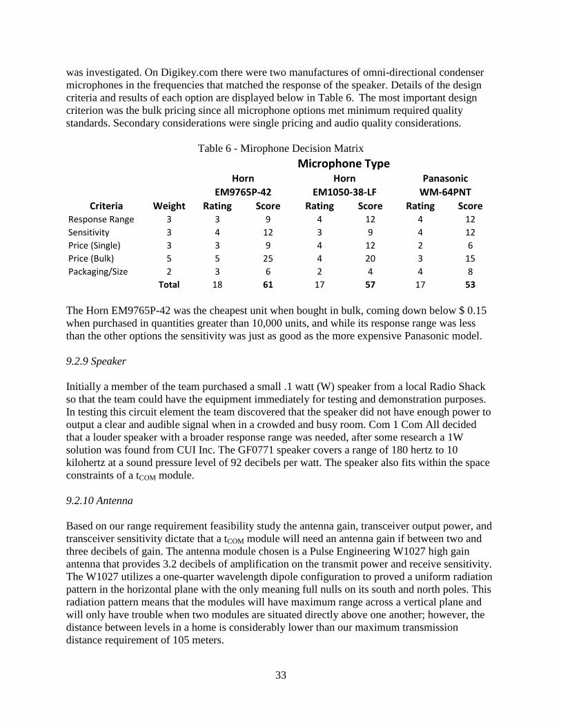
33
was investigated. On Digikey.com there were two manufactures of omni-directional condenser
microphones in the frequencies that matched the response of the speaker. Details of the design
criteria and results of each option are displayed below in Table 6. The most important design
criterion was the bulk pricing since all microphone options met minimum required quality
standards. Secondary considerations were single pricing and audio quality considerations.
Table 6 - Mirophone Decision Matrix
Criteria Weight Rating Score Rating Score Rating ScoreResponse Range 3 3 9 4 12 4 12
Sensitivity 3 4 12 3 9 4 12
Price (Single) 3 3 9 4 12 2 6
Price (Bulk) 5 5 25 4 20 3 15
Packaging/Size 2 3 6 2 4 4 8
Total 18 61 17 57 17 53
Microphone Type
EM9765P-42 EM1050-38-LF WM-64PNT
Horn Horn Panasonic
The Horn EM9765P-42 was the cheapest unit when bought in bulk, coming down below $ 0.15
when purchased in quantities greater than 10,000 units, and while its response range was less
than the other options the sensitivity was just as good as the more expensive Panasonic model.
9.2.9 Speaker
Initially a member of the team purchased a small .1 watt (W) speaker from a local Radio Shack
so that the team could have the equipment immediately for testing and demonstration purposes.
In testing this circuit element the team discovered that the speaker did not have enough power to
output a clear and audible signal when in a crowded and busy room. Com 1 Com All decided
that a louder speaker with a broader response range was needed, after some research a 1W
solution was found from CUI Inc. The GF0771 speaker covers a range of 180 hertz to 10
kilohertz at a sound pressure level of 92 decibels per watt. The speaker also fits within the space
constraints of a tCOM module.
9.2.10 Antenna
Based on our range requirement feasibility study the antenna gain, transceiver output power, and
transceiver sensitivity dictate that a tCOM module will need an antenna gain if between two and
three decibels of gain. The antenna module chosen is a Pulse Engineering W1027 high gain
antenna that provides 3.2 decibels of amplification on the transmit power and receive sensitivity.
The W1027 utilizes a one-quarter wavelength dipole configuration to proved a uniform radiation
pattern in the horizontal plane with the only meaning full nulls on its south and north poles. This
radiation pattern means that the modules will have maximum range across a vertical plane and
will only have trouble when two modules are situated directly above one another; however, the
distance between levels in a home is considerably lower than our maximum transmission
distance requirement of 105 meters.

34
9.2.11 Additional Analog Circuitry
Additional circuitry will be required to maximize the utility of components, including tuning
networks for the transceiver, capacitors to mitigate pin capacitances, and filters and amplification
for analog audio. These components are not projected to have a large impact on the final cost of
tCOM modules, and the total scope of the required additional circuitry is still an unknown and will
be fleshed out during the prototyping stage of the design.
9.2.12 Power Supply
Some intercoms run on expensive but convenient batteries, tCOM runs on the cheap power
available from home power lines. There are two versions of this power supply. One is intended
for prototyping and the other is for production. This separation will allow Com 1 Com All to
focus more on digital system design and less on analog design.
9.2.12.1 Prototype Supply
The prototype design uses a power adapter to handle most of the power regulation. The use of
the adapter allows for minimal on-board components to regulate the remaining direct current
voltage. The power adapter also reduces the heat of internal components. It is quite likely that
the end user desires the flexibility of plugging the tCOM into a wall outlet, so this functionality is
also available on the production supply as well. This setup does not integrate well with a wall
mountable design which encouraged a change for the final production design.
9.2.12.2 Final Production Supply
The final production supply incorporates the power adapter’s functionality into on-board
circuitry. This incorporation is far more practical in production because the use of surface mount
parts makes less expensive and space intensive. The on-board transformer still requires
significant space, but the other components reduction from using surface mount equivalents
should help offset the space. The advantage of an on-board adapter is that the units would
become wall mountable for a superior integration in homes. A plug would still be provided for
the option of plugging into an electrical outlet.
9.2.13 Circuit board layout
During the preliminary stages of our design, there is no need for a full circuit board design until all parts
have been selected and preliminary testing on individual system components is completed. Until that
point, there is still some preliminary board design work for testing purposes of individual components.
For testing of the audio codec and transceiver control with our PIC microcontroller development kit, it
will be necessary to create a daughter boards for each of these surface mount chips to interface with the
breadboard on the microcontroller development board. Although relatively small designs, these will be
important initial steps towards a final board design as well as a necessary addition for initial testing of the
components. These designs will be completed over the Christmas break and ready to be used for testing
at beginning of January.
9.2.14 Product packaging

35
Prototype versions of the tCOM system will not include a packaging solution however for the
production model the packaging will likely be constructed of a polymer or resin for ease of mass
manufacture and their lesser effect on RF transmissions than a metal case. RF interference
properties of the selected material will have to be taken into account when tuning the antenna.
Polymers and resins can also be made in several colors at creation, rather than having to paint the
final product. Initially tCOM will be available in a range of colors suitable for interior use,
including: white, beige, and black. Special attention will be paid to the texture of the plastic, as it
will have an effect on the perceived quality of the product as well as the ease of cleaning.
9.2.15 Current Block Diagram
Below in Figure 9 is the current hardware block diagram displaying our hardware design choices
and the communications protocols between communicating blocks.
Nodic
nRF24L01
PIC
18F45J10
8074111
Audio
Codec
Crystalfontz
FCAH1602O-YYH-ET
SP
I
SPI
CUI Inc
GF0771
PSU
Horn EM9765P-42
Pulse W1027
Pa
ralle
l
Phillips
PCF8563 Real
Time Clock
I2C
Figure 9 - Current Hardware Block Diagram
10.3 Software Design
The preliminary design’s software is best represented in sections or routines that focus on certain
aspects of the Intercom’s functionality. These routines frequently incorporate other the other
devices controlled by the microprocessor. The preliminary design’s routines and their interfaces
can be seen below in Figure 10.

36
Figure 10 - Software Block Diagram
10.3.1 Auto Setup
A key feature of tCOM is its ability to automatically detect and set up a wireless network without
any user programming. This feature will be implemented in the Auto Setup routine with the help
of the Network routine. The Auto Setup will look for an existing open network to connect to. If
detected, the routine will obtain network information including addressing, module names, and
the encryption key. If no open network is available, the routine will assume a preprogrammed
encryption key. A generic module name will be assigned if none exists in the memory. The
Auto Setup directly interfaces with the power supply in that upon powering up, the Auto Setup is
initiated. The watchdog routine may also restart the software by calling Auto Setup. The Auto
Setup is also responsible for reestablishing the network in the case of a power failure.
10.3.2 Network
The network routine directly interfaces with the transceiver. It sends data and network info
requests to and from other routines and implements the data protocol. The network routine must

37
establish a network frequency when communicating with other modules in order to avoid
collisions with other module requests.
10.3.3 Update
The Update routine is a relatively simple routine that updates key network information such as
module name changes, new module connections, and clock updates. This routine is intended to
synchronize information on the network and provide features like timeSYNC and nameSYNC.
10.3.4 Top Menu
The Top Menu routine is the interface control center. It updates the clock by directly interfacing
with the LCD and allows for user interaction by interfacing with the buttons and scroll wheel.
The Top Menu runs most of the other routines allowing access of the many features of tCOM to
the end user. As its name implies, Top Menu is menu based to facilitate use. Menu options
include call, clock, change name, and hot buttons. Hot button changes are stored in memory and
in registers. Other selections run their respective routines. This is the default routine after
periods of disuse.
10.3.5 Call and Receive
The Call and Receive routines directly interface with the transceiver to control the flow of data
during module communication. Like the Network routine, they implement the data protocol and
work in conjunction with the Talk and Listen routine to transfer audio. It is extremely important
to make these sections as efficient as possible as they will be the most processing intensive and
poorly written code could reduce audio quality.
10.3.6 Talk and Listen
The Talk and Listen routine directly interfaces with the audio codec. It will be able to control
the volume settings as well as any of the other features available through the codec. Should the
Talk and Listen routine when combined with the Call and Receive routines become too processor
intensive, a second microprocessor dedicated to interfacing the codec will be added to separate
these tasks.
10.3.7 Alarm and Clock Set
The Alarm and Clock Set routine directly interfaces with the Real Time Clock to change clock
settings and also sets control registers for the alarm. Changes to the clock can be sent across the
network through the update routine.

38
10.3.8 Watchdog
While much of the watchdog is in fact separate hardware on the microprocessor, the control of
this automated function will be set with the Watchdog routine. This routine will reset a
watchdog timer to indicate that the entire program is functioning correctly. If the program
should freeze for some reason, the watchdog will reset the program and initiate the Auto Setup
routine. The Watchdog routine will also be used to periodically send the program to sleep during
periods of inactivity in order to conserve power.
10.4 Network Protocol
Network protocols are extremely important for wireless systems. They provide the means for
communication and transmission validation between wireless transceivers. In the case of a tCOM
network, the network protocol enables important feature such as updating the network, adding
new modules, and making calls. The protocol is 32 bytes long and includes a section for
instruction, address, and data. While many protocols include handshaking within the instruction
set, tCOM’s transceiver can automatically be set to acknowledge transmissions. Because of this
automatic handshaking, there is no need for a separate handshaking instruction. The complete
instruction set for tCOM’s network protocol can be seen below in Table 7.
Table 7 – Network Protocol Instruction Set Instruction(1B) Addr(1B) END(1B)Call Request 0hXX Frequency(1B) End(1B)
Monitor Request 0hXX Frequency(1B) End(1B)
Talk Start 0hXX End(1B)
Talk End 0hXX End(1B)
Call End 0hXX End(1B)
New Module Request 0hFF Addr(1B) End(1B)
New Module Return 0hFF 0 Network Frequency(1B) Network Addr(3B) Encryption Key(16B) Clock(8B) Empty(1B) End(1B)
0hFF 1 Addr(1B) Name(16B) End(1B)
Update 0hXX 0 Network Frequency(1B) Clock(8B) End(1B)
0hXX 1 Addr(1B) Name(16B) End(1B)
Empty(29B)
Empty(12B)
Empty(22B)
Empty(12B)
Empty(28B)
Empty(29B)
Empty(29B)
Empty(28B)
Data(29B)Empty(28B)
10.4.1 Call Request and Monitor
Perhaps the most important instructions in tCOM’s instruction set are the Call Request and
Monitor instructions. These instructions tell other modules when to expect audio data packets
and where to expect them. The Call Request instruction sends information to all of the other
modules on the network. The address portion communicates to each module if they are the
intended recipient of the request. The frequency portion tells each module on which frequency
the audio data will be transmitted. Similarly, the Monitor Request also communicates which
module is being monitored and on which frequency the module should send its audio data. The
Monitor Request instruction must be resent after every second to continue audio reception from
the destination module.
10.4.1 Talk Start, Talk End, and Call End
Because the audio data sent from module to module is usually continuous and for undefined
lengths of time, it is necessary for each module to communicate when they would like to talk and
when they are done talking. The Talk Start and Talk End instructions achieve this goal.
39
Likewise, the Call End instruction alerts the other module that the entire conversation is over and
that the module should return to the network frequency. If for some reason an instruction or data
packet is not received by the module for an appropriate length of time, the module assumes that
the transmission has been terminated and returns to the network frequency automatically.
10.4.2 New Module Request and New Module Return
The New Module Request instruction is only used during the Auto Setup routine for a module
that has not already been networked. After the New Module Request has been sent, a New
Module Return is sent back to the requesting module if a module already on the network has
been set to accept new modules by the user. If no New Module Return is received after 15
requests, the module assumes that there is no network available and sets up its own network
based on preprogrammed randomized values. The Network Module Return sends key network
information including the network frequency, network address, 128 bit encryption key, and
network clock. The Network Module Return can also send the addresses and names of the other
modules on the network after which it can indicate the end of transmission. Both instructions
use the 0xff address for speaking to all modules because neither module knows the other’s
address.
10.4.3 Update
The Update instruction allows a module to make changes to the network clock, frequency, and
the modules own name. The instigating module sends this instruction to each module on the
network and must try again if the some of the modules are unavailable.
11.0 Feasibility study
11.1 Audio Quality Study
While some of the competition may incorporate minimal quality audio systems in order to reduce
cost, because tCOM is targeting upper middle class and commercial markets that desire increase in
functionality, audio quality will be a significant factor for sales and design. Other similar
devices have very poor audio quality to the point of user annoyance or even information loss.
Such devices include walkie-talkies, phones, and low quality toys. On the opposite spectrum
DVD’s and CD’s are known for their excellent audio quality. For these reasons, the goal of the
tCOM’s audio quality is to exceed that of a phone and approach that of a CD.
11.1.1 Bit Depth
Audio quality is a difficult thing to define even though it is very apparent to the sensitive human
ear. One measure of the quality is the bit depth of the signal. Bit depth refers to the divisions of
sound levels in the signal. For instance, a signal with a bit depth of one would have 21 sound
levels. This signal would only be able to produce square waves at one volume. A signal with a
bit depth of three would have 23 = 8 different sound levels and one with sixteen would have
216
=65536. Since natural occurring signals are produced by vibrations in the air, desired signals

40
have a sine wave shape. This shape is far better approximated by the sixteen bit signal then by
the three or one bit as seen below in Figure 11 below.
Figure 11 - Signal Approximation with Bit Resolution (zone.ni.com)
This differentiation becomes more important and noticeable with smaller signals and with
approximating complex frequencies like voices that have many frequencies present as the same
time. The necessity of having more than 16 bits or even just 8 bits of depth for a signal may
seem excessive, but even moving from 16 to 24 bit signals can improve overtones and nuances
(extremetech.com). The bit depth of a common telephone is 8 bits and a CD frequently has 24
bits.
11.1.2 Frequency Range
A second measure of audio quality is the frequency range of a signal. The human ear can
differentiate frequencies from 20-20,000Hz. To perfectly replicate audible sounds, these
frequencies must be covered and sometimes sub-audible signals are included to feel s sounds like
those of a jet engine. When converting an analog signal into digital, the frequency range of the
result is determined by the sample rate. This sample rate is exactly twice as fast as the fastest
frequency in the desired range. This is why CD’s which cover the entire audible spectrum must
sample at a rate of 44.1 kHz. The telephone’s frequency range of 180-3.2 kHz is a clear
indicator of its far lower quality. In general, frequency range is far more noticeable then bit
depth and is a far greater factor in total audio quality. Unfortunately, increasing the frequency
range of an audio system is far more expensive then increasing its bit depth. It is especially
expensive for small sized systems, because larger speakers are needed for producing lower
frequencies and space is sometimes too limited for multiple speakers.
11.1.3 Noise
Even more apparent than a reduced frequency range is the introduction of noise to a signal.
Noise often is heard as a crackling or whining sound. Noise can occur from a multitude of

41
different sources including the supply lines to speaker, microphone, or codec, crosstalk between
lines, electromagnetic pollution, and poor data transmission. In fact, it is noise induced from
home power lines that inspired the conception for the tCOM. In terms of noise, a digital system
has significant advantages over analog. However, any audio system will need to incorporate at
least some analog circuitry. Because tCOM’s data will be transmitted over RF, poor signal
reception may cause intermittent connections. This makes the transceiver the most crucial
component effecting audio quality.
11.1.4 Audio Quality of Design
tCOM incorporates all of the audio quality issues mentioned above to provide for affordable but
high quality sound. By using slightly more expensive parts, tCOM is designed to have a bit depth
of 24, a frequency range of 180-12,000Hz, and as little noise as possible especially when the
speaker is not being used during listen mode. Bottlenecks for tCOM’s designed bit rate are the
transceiver and microprocessor. These components must be able to handle the 576kb/s required
to move a 12kHz signal with a bit depth of 24. Any further range extension will only increase
the bit rate and subsequently the transceiver’s and microprocessor’s necessary performance. The
chosen components account for the desired bit rate to ensure the desired audio quality. This
expected quality is far better than a telephone’s 180-3.2kHz 8b signal but not quite as good as
that of a CD’s 20-20kHz 24b sound.
11.2 Data Transfer Analysis
To achieve the desired audio quality mentioned in the Audio Quality Study section above, all of
the components must be able to transfer at the necessary data rate. A failure of a component to
comply with this rate would lower the quality of sound and if unaccounted for, cause
unacceptable distortion. These data rates must be carefully calculated because data rates given in
data sheets can be very misleading. The needed transfer calculations can be found in Appendix
C and result in a rate of 576,000 bps (bits per second).
11.2.1 Transceiver
According to the transceiver data sheet, the nRF24L01 transmits at 2 Mbps or 1Mbps. Allowing for some packaging inefficiencies expected to add up to 50% of the data transmitted, it initially appears to more than cover the desired bit rate even at low speed. A more careful analysis of the data sheet showed that this assumption was not true. As seen in the calculation found in Appendix C, the actual maximum rates are closer to 584 kbps and 906 kbps. These results make using the lower transmission rate too risky and leave no room at the higher rate for acknowledgement of individual packets.
11.2.2 Codec
The codec is designed to convert analog and digital signals at sample rates of 48 kHz and up to
24 bits of depth. Thus the theoretical bit rate for the codec is 1.1152 Mbps. Not only is this well
above the needed rate, but also indicates that the device will not reduce quality to keep up.

42
11.2.3 Microprocessor
The microprocessor has two areas with possible transmission rates. Using only the general
input-output ports, the processor can transfer raw data at a rate over 1MHz. However, tCOM’s
other features make using the processor’s computing power inefficient and undesirable. The
SPI (serial peripheral interface) capabilities of the PIC18F45J10 allow for up to 10 Mbps transfer
rates that do not use software or PIC computing power. Both codec and processor were chosen
to coordinate in their peripheral support of SPI to facilitate the requirements of data transfer and
ease of programming.
11.3 Power Consumption Analysis
Because tCOM is designed for quality and functionality, the power supply must provide adequate
power to all of the components without overheating. Partially for this reason, IC’s were the most
common choice for components reducing the total need for power. A list of the components
used in tCOM’s design can be found below in Table 8.
Table 8 - Component Power Requirements
Device/Component Max Power(mW) Sleep(mW) Active (mW)
PIC Processor 1000.0 0.7 568
Audio Codec 35.0 1.9 35.0
Microphone 5.0 2.3 2.3
Speaker 1000.0 0.0 500
Transciever 60.0 0.1 36.9
LCD 826.5 7.5 7.5
Real Time Clock 4.4 0.0 4.4
Additional Circuitry 200 1 100
Total 3130.9 13.3 1254.1
While over three watts of power is far beyond the expected power requirements for an intercom,
it is a value that will likely never be needed. To max out all of the components, the end user
must be receiving a transmission with the backlight on at a constant full volume. The PIC’s
maximum assumes that the output pins are providing their max total output current of 200mA.
This will never happen because tCOM does not require the PIC to drive any of the surrounding
circuitry. A more accurate estimation, the active power, is a better indicator of tCOM’s power
needs until prototypes can be built and tested for consumption rates. A max power usage of 1.25
W is below our 5.324W requirement.
11.4 Economic analysis
Cost estimates are important for determining the marketability and the budget of a design. As
already mentioned in the Detailed Design Requirements, tCOM needs to cost 20$ or less to
manufacture to reach its goals. This requirement is extremely tight and a small amount of
overshoot may be deemed acceptable for additional features. In terms of budgeting, Com 1 Com
All has only $300 to spend on resources. Therefore $300 is the desired total spending unless

43
additional funding from other senior design allotments can be redistributed to tCOM’s
development.
11.4.1 Parts List and Bill of Material
The total amount of money expected to be spent on tCOM including projected bulk pricing can be
found below in Table 9.
Table 9 - Cost For Purchased and Needed Parts Item Description Sing. Cost($) Multi Cost($) Qty Needed Qty Bought Sing. Sub Tot Multi Sub Tot
DV164120 DEV KIT 50 0 0 1 50 0
PIC16F685-I/P PIC 3 1.14 0 1 3 1.14
PIC18F45J10 PIC 0 1.79 3 0 0 1.79
PIC24FJ16GA004 PIC 0 1.84 3 0 0 1.84
AD74111YRUZ Codec 5 2.66 1 2 15 2.66
EM9765P-42 Microphone 0.98 0.147 3 0 2.94 0.147
GF0771 Speaker 3.6 1.92 3 0 10.8 1.92
nRF24L01 Transciever 2.05 1 0 4 8.2 1
w1027 Antenna 4.65 1.97 3 0 13.95 1.97
PCF8563 Real Time Clock 1.33 0.6625 3 0 3.99 0.6625
CFAH1602O-YYH-ET LCD 19.24 3.3 3 0 57.72 3.3
Human Interface Devices Buttons and Scroll 5 1.5 3 0 15 1.5
Boards Final Boards 25 1 3 0 75 1
Packaging Packaging 0 1 3 0 0 1
Contingency Contingency 50 0 1 0 50 0
PSU Power Supply 10 1 0 0 0 1
Shipping Shipping 25 0.1 0.72 0.28 25 0.1
Total 78.2 330.6 18.0495
Table 4 clearly shows that tCOM’s total cost with a $50 contingency is $330.6 which is more than
the goal. While goal can be reached if the contingency is unneeded, it is far more likely that
Com 1 Com All will require additional funding. The total under the multi subtotal calculates the
cost of a single module’s materials using only the PIC18F45J10. This total is very close to the
goal of $20 per module, but costs are based on actual bulk rates available online and it may be
possible to negotiate better deals in an actual business setting. Bulk pricing was unavailable for
the transceiver so a conservative half pricing was assumed.
11.4.2 Manufacturing Costs
Additional cost such as labor, shipping, and machine maintenance make the actual cost of
production higher than merely the cost of materials. These rough estimates and assumptions can
be found in Appendix D. Added to the estimated cost of materials, the total production cost
comes out to $19.8915. This is below our goal of $20 and is conservative because of the lack of
availability of certain bulk prices and production costs.
12.0 Test Plans
To ensure that our designs are meeting the functional requirements of the tCOM, thorough testing
of key requirements must take place during and after the prototyping stages.
44
12.1 Prototype Testing Method
We plan on implementing much of our testing to individual blocks of the design while they are
being prototyped. After the block has shown it meets the requirements we have set, it will then
be saved until further implementation on the system level. Final functionality tests will be
undertaken once the system has been completely implemented. The following sections indicate
design areas which will require testing during the prototype stage.
12.1.1 Audio Quality
This test will check the audio codec’s ability to tack input audio from a microphone and pass it
out to a speaker after converting it to digital form and passing it through the microcontroller.
When this can be done effectively and provide clear sound from the speaker, the testing will be
complete.
12.1.2 Data Transmission
The transceiver must first be able to transmit any data over the wireless connection before we
can move to audio transmission. Using the microcontroller to configure and control two
transceivers, we will transmit a previously determined data packet over multiple frequency
channels. This will show we are able to change frequencies and successfully transmit data.
12.1.3 Transmission of Audio
This test will show that the microprocessor is able to handle both the tasks of transferring audio
data to and from the codec and the transceivers in a manner which will allow for audio
transmission. Only with proper hardware and software configurations will the transmission be
able to take place. Completing this test will be essential to making working prototypes. Success
will be defined as wirelessly transmitting an input audio signal and hearing it at the output
speaker of the other intercom prototype.
12.1.4 Networking
Networking testing will show that the microcontroller with the help of the transceiver will be
able to set up a network, and complete additional networking tasks. This testing is far less
intensive on precise coding and will probably take place before audio transmission.
12.1.5 LCD Control
The microcontroller must be able to initialize and update the LCD screen based on software
design. Completion of this test will allow the LCD to be used in other test areas.
12.1.6 Clock and Alarms
These tests will show that the coding for clock and alarm routines work as required. This will
also include clock change synchronization over a network of two intercoms. The alarm test will
45
show that the microprocessor can properly keep track of the time based on signals from the real
time clock.
12.1.7 Power Usage
This test will be to check the on board voltage regulation and ensure that they provide the
necessary voltages for our integrated circuits. It will also need to be completed again when the
power system is connected to the full system.
12.2 Final Test Method
We will have two main types of testing once the entire system prototypes are built and are
functioning properly. They are described in the sections below.
12.2.1 User Functionality Testing
This will be the equivalent of a full user testing of all the functionality required of the system.
Three prototypes will be involved in testing audio transmission in all com connection variations.
Also all networking tasks will be carried out multiple times to confirm their functionality. Any
problems in the functionality will be addressed through software debugging and hardware
debugging if necessary. The hope is that earlier testing will resolve most if not all of the major
issues in system block designs.
12.2.2 System Endurance Testing
Due to the possible use of the tCOM as a baby monitor, it will also be necessary to show that the
system will be able to work properly while transmitting audio for a long continuous period of
time. We will do this under constant supervision in case the system happened to fail during the
testing process. Checks of all the power requirements should also be done near the end of the
test due to the continual load placed on the power supply unit during a long period of
transmitting, receiving, and outputting audio. This test will show the robust nature of the
components selected for our design and the system design as a whole.
12.2.3 Range Testing
Two intercom modules will be used to transmit audio in an open outdoor area and will be moved
further away until the maximum system range is determined. This will be defined as the distance
at which the wireless audio transmission ceases to provide adequate audio on the output.
13.0 Task breakdown and time schedule
The overall Project has been broken down into several categories of work including: hardware,
software, analysis, prototyping, documentation and prototyping. In Figure 12 the hardware,
analysis, and documentation tabs have been expanded to show the areas that have received the
greatest amount of attention this semester. The figure also displays the projected schedule for
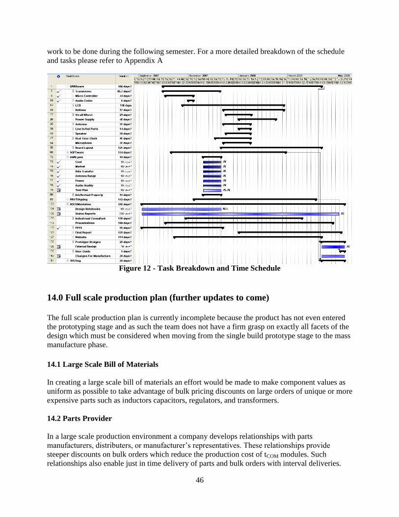
46
work to be done during the following semester. For a more detailed breakdown of the schedule
and tasks please refer to Appendix A
Figure 12 - Task Breakdown and Time Schedule
14.0 Full scale production plan (further updates to come)
The full scale production plan is currently incomplete because the product has not even entered
the prototyping stage and as such the team does not have a firm grasp on exactly all facets of the
design which must be considered when moving from the single build prototype stage to the mass
manufacture phase.
14.1 Large Scale Bill of Materials
In creating a large scale bill of materials an effort would be made to make component values as
uniform as possible to take advantage of bulk pricing discounts on large orders of unique or more
expensive parts such as inductors capacitors, regulators, and transformers.
14.2 Parts Provider
In a large scale production environment a company develops relationships with parts
manufacturers, distributers, or manufacturer’s representatives. These relationships provide
steeper discounts on bulk orders which reduce the production cost of tCOM modules. Such
relationships also enable just in time delivery of parts and bulk orders with interval deliveries.

47
14.3 Product Assembler
To achieve the desired economies of scale, printed circuit board assembly must be completed by
an automated part placement and testing suite. This approach to assembly limits the number of
people required to produce each board, directly reducing the cost to manufacture each board
since labor accounts for roughly eighty percent of projected non-material production cost.
14.4 Compliance Testing
The final product must pass FCC (Federal Communication Commission) regulations to be
marketed in the United States, and other regulating bodies for sale abroad. An outside testing
firm is required to certify that the product meets all regulations; therefore the tCOM system
modules would have to be submitted to one such testing firm. Underwriters Laboratories (UL) is
the oldest and most widely known testing company in the United States; however there are
several more testing firms, which will certify a product in compliance with FCC regulation.

48
Appendices
Appendix A: Expanded Task List and Schedule

49
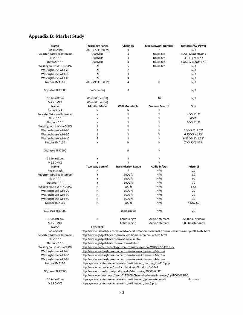
50
Appendix B: Market Study
Name Frequency Range Channels Max Network Number Batteries/AC Power
Radio Shack 200 - 270 kHz (FM) 3 ? N/Y
Reporter Wirefree Intercom 900 MHz 4 Unlimited 4 AA (12 months)/ Y
Flush '' '' '' 900 MHz 4 Unlimited 4 C (3 years)/ Y
Outdoor " " " 900 MHz 4 Unlimited 4 AA (12 months)/ N
Westinghouse WHI-4CUPG FM 5 Unlimited N/Y
Westinghouse WHI-2C FM 2 N/Y
Westinghouse WHI-3C FM 3 N/Y
Westinghouse WHI-4C FM 4 N/Y
Nutone IMA110 200 - 290 kHz (FM) 4 8 N/Y
GE/Jasco TL97600 home wiring 3 N/Y
GE SmartCom Wired (Ethernet) 16 N/Y
M&S DMC1 Wired (Ethernet)
Name Monitor Mode Wall Mountable Volume Control Size
Radio Shack N N Y
Reporter Wirefree Intercom Y Y Y 4"x5.5"x2"
Flush '' '' '' Y Y Y 6"x7"
Outdoor " " " Y Y Y 6"x3.5"x2"
Westinghouse WHI-4CUPG ? Y Y
Westinghouse WHI-2C ? Y Y 5.5"x5.5"x1.75"
Westinghouse WHI-3C ? Y Y 6.75"x5"x1.75"
Westinghouse WHI-4C ? Y Y 6.25"x5.5"x1.25"
Nutone IMA110 Y N Y 7"x5.75"1.875"
GE/Jasco TL97600 N Y
GE SmartCom Y Y Y
M&S DMC1 Y Y Y
Name Two Way Comm? Transmission Range Audio In/Out Price (1)
Radio Shack N ? N/N 20
Reporter Wirefree Intercom Y 1000 ft N/N 89
Flush '' '' '' Y 1000 ft N/N 99
Outdoor " " " Y 1000 ft N/N 79
Westinghouse WHI-4CUPG N 500 ft N/N 62.5
Westinghouse WHI-2C N 1500 ft N/N 20
Westinghouse WHI-3C N 1500 ft N/N 27
Westinghouse WHI-4C N 1500 ft N/N 35
Nutone IMA110 N 500 ft N/N 43/62.50
GE/Jasco TL97600 same circuit N/N 20
GE SmartCom N Cable Length Audio/Intercom 2200 (full system)
M&S DMC1 Cable Length Audio/Intercom 500 (master only)
Name Hyperlink
Radio Shack http://www.radioshack.com/sm-advanced-3-station-3-channel-fm-wireless-intercom--pi-2036287.html
Reporter Wirefree Intercom http://www.gadgetshack.com/wireless-home-intercom-system.html
Flush '' '' '' http://www.gadgetshack.com/waflmowiin.html
Outdoor " " " http://www.gadgetshack.com/ouwiinad.html
Westinghouse WHI-4CUPG http://www.home-technology-store.com/intercom/W-WHDBI-5C-KIT.aspx
Westinghouse WHI-2C http://www.westinghouse-home.com/wireless-intercoms-2ch.htm
Westinghouse WHI-3C http://www.westinghouse-home.com/wireless-intercoms-3ch.htm
Westinghouse WHI-4C http://www.westinghouse-home.com/wireless-intercoms-4ch.htm
Nutone IMA110 https://www.centralvacuumstores.com/intercom/nutone_ima110.php
http://www.nutone.com/product-detail.asp?ProductID=3042
GE/Jasco TL97600 http://www.stores9.com/product-info/electronics/B000069J9C
http://www.amazon.com/Jasco-TL97600-Channel-Wireless-Intercom/dp/B000069J9C
GE SmartCom https://www.centralvacuumstores.com/intercom/ge_smartcom.php 4 rooms
M&S DMC1 https://www.centralvacuumstores.com/intercom/dmc1.php
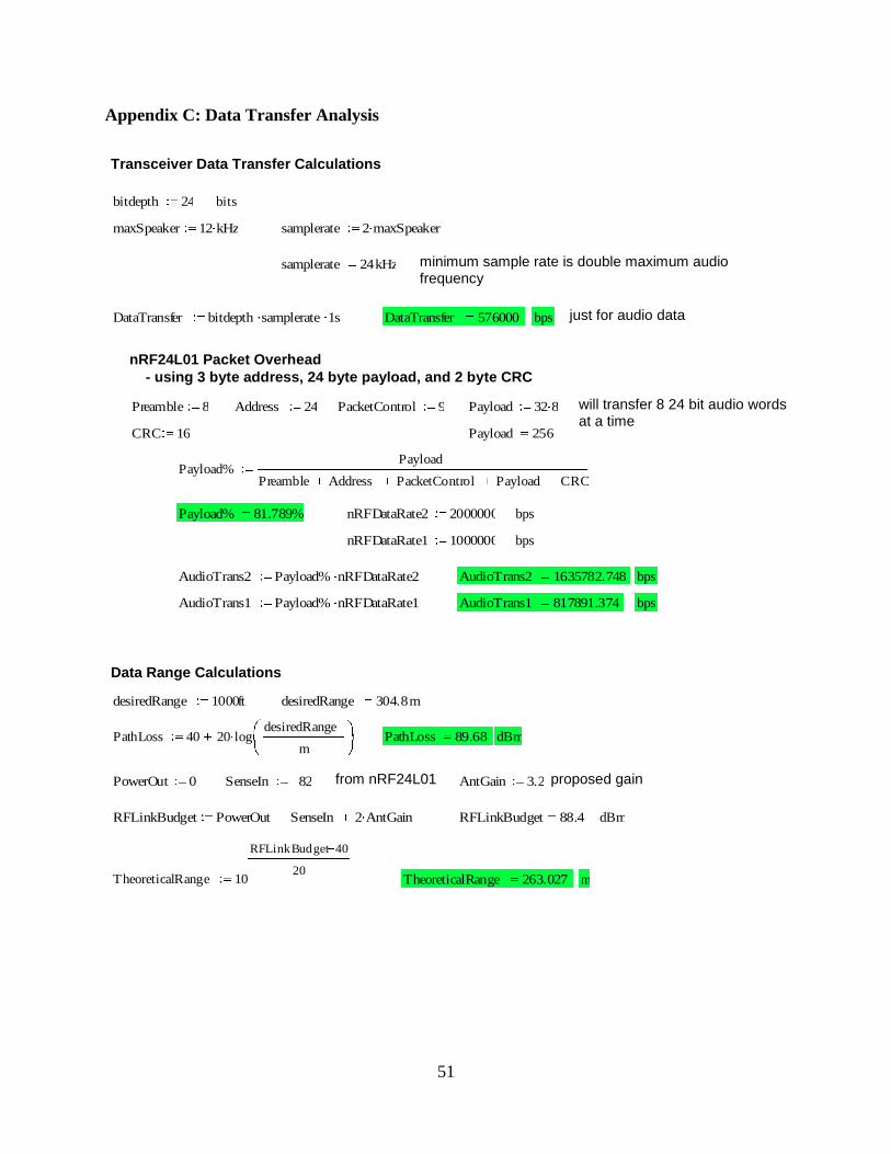
51
Appendix C: Data Transfer Analysis
Transceiver Data Transfer Calculations
bitdepth 24 bits
maxSpeaker 12 kHz samplerate 2 maxSpeaker
samplerate 24kHz minimum sample rate is double maximum audio frequency
DataTransfer bitdepth samplerate 1s DataTransfer 576000 bps just for audio data
nRF24L01 Packet Overhead
- using 3 byte address, 24 byte payload, and 2 byte CRC
Preamble 8 Address 24 PacketControl 9 Payload 32 8 will transfer 8 24 bit audio words at a time
CRC 16 Payload 256
Payload%Payload
Preamble Address PacketControl Payload CRC
Payload% 81.789% nRFDataRate2 2000000 bps
nRFDataRate1 1000000 bps
AudioTrans2 Payload% nRFDataRate2 AudioTrans2 1635782.748 bps
AudioTrans1 Payload% nRFDataRate1 AudioTrans1 817891.374 bps
Data Range Calculations
desiredRange 1000ft desiredRange 304.8m
PathLoss 40 20 logdesiredRange
m PathLoss 89.68 dBm
PowerOut 0 SenseIn 82 from nRF24L01 AntGain 3.2 proposed gain
RFLinkBudget PowerOut SenseIn 2 AntGain RFLinkBudget 88.4 dBm
TheoreticalRange 10
RFLinkBudget 40
20 TheoreticalRange 263.027 m
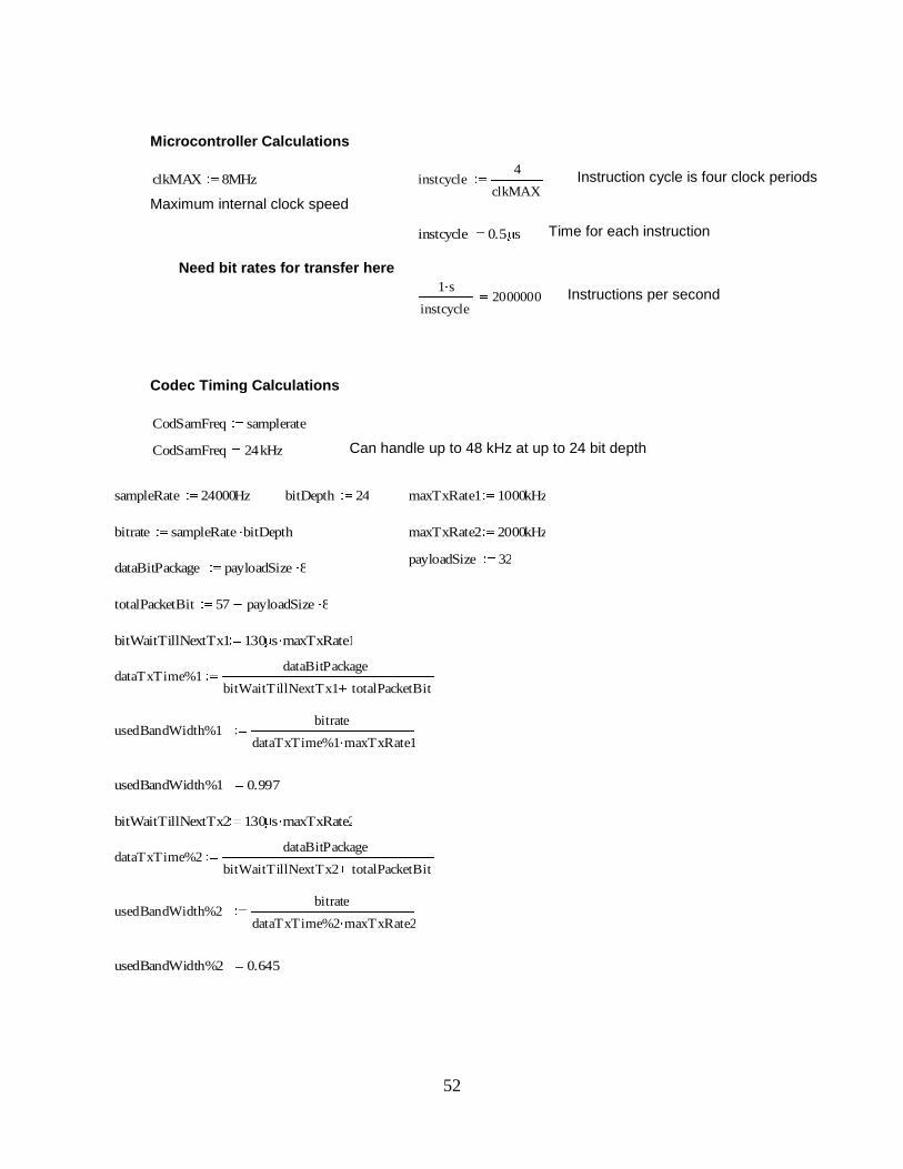
52
Microcontroller Calculations
clkMAX 8MHz instcycle4
clkMAX Instruction cycle is four clock periods
Maximum internal clock speed
instcycle 0.5 s Time for each instruction
Need bit rates for transfer here
1 s
instcycle2000000 Instructions per second
Codec Timing Calculations
CodSamFreq samplerate
CodSamFreq 24kHz Can handle up to 48 kHz at up to 24 bit depth
sampleRate 24000Hz bitDepth 24 maxTxRate1 1000kHz
bitrate sampleRate bitDepth maxTxRate2 2000kHz
payloadSize 32 dataBitPackage payloadSize 8
totalPacketBit 57 payloadSize 8
bitWaitTillNextTx1 130 s maxTxRate1
dataTxTime%1dataBitPackage
bitWaitTillNextTx1 totalPacketBit
usedBandWidth%1bitrate
dataTxTime%1 maxTxRate1
usedBandWidth%1 0.997
bitWaitTillNextTx2 130 s maxTxRate2
dataTxTime%2dataBitPackage
bitWaitTillNextTx2 totalPacketBit
usedBandWidth%2bitrate
dataTxTime%2 maxTxRate2
usedBandWidth%2 0.645

53
Appendix D: Production Cost
numberOfBoardsPerWorkDay2000
8hr
costOfLabor25
hr costOfMachineMaintenance
500000
yr
workersMachineOperators 2 percentOverchangeForProfitAndManagement 1.5
workersFinalAssembly 5
workersTestingAndPackaging 3
totalWorkers workersTestingAndPackaging workersFinalAssembly workersMachineOperators
productionCostOfLabortotalWorkers costOfLabor( ) percentOverchangeForProfitAndManagement
numberOfBoardsPerWorkDay
productionCostOfMaintenancecostOfMachineMaintenance percentOverchangeForProfitAndManagement
numberOfBoardsPerWorkDay
ProductionCostPerBoard productionCostOfMaintenance productionCostOfLabor
Maintenance%productionCostOfMaintenance
ProductionCostPerBoard Maintenance% 18.577%
Labor%productionCostOfLabor
ProductionCostPerBoard Labor% 81.423%
ProductionCostPerBoard 1.842
Assumption: These assumptions were primarily based on actual production data and experience at Gentex, a auto-dimming mirror manufacturing company. The cost of labor is assumed to be no more than 18$/hr pluss an additional 7$/hr for benifits and liability coverage. The cost of machine maintenance is intentially high because it shows how little it contributes to the final cost and to add extra wiggle room since actual cost is less available then the cost of labor. The extra 50% charge is added for covering manament costs, fixed costs like machines, and leave enough left over for an acceptable profit.


