107
PROJECT RAND (AAF PROJECT MX-791) COMMUNICATION AND OBSERVATION PROBLEMS OF A SATELLITE D. K. BAilEY • A. S. MENGel RA-15028 February 1,1947 DOUGLAS AIRCRAFT COMPANY, INC.

PROJECT RAND (AAF PROJECT MX-791)
COMMUNICATION AND OBSERVATION
PROBLEMS OF A SATELLITE
D. K. BAilEY • A. S. MENGel
RA-15028
February 1,1947
DOUGLAS AIRCRAFT COMPANY, INC.

TABLE OF CONTENTS
SUMMARy ........................................................................... vii
I • INTROOUCT ION .............................................•................... 1
II. REQUIREMENTS AND LIMITATla'JS .............................................. 2
II-A. DURING LAUNCHING .................................................... 3
II-B. ON ORBIT ............................................................. 6
I I I • INFLUENCE OF THE ATMOSPHERE ............................................... 8
III-A. ABS~PTION ........................................................... 9
III-B. REFRACTION .......................................................... 11
III-B-l. Refraction of Light Waves .................................... 11
III-B-2. Refraction of Radio Waves .................................... 14
III-B-2-a. In the Lower Atmosphere .......... ................. 15 III-B-2-b. In the Ionosphere .. ..............•................ 16
III-B-3. Parallactic Corrections to Refraction ....•..•...... ' .......... 22
III-B-3-a. For Light and Radio Waves &fracted by the Lower AtllOsphere . ....................................... 22
IlI-B-3-b. For Radio Waves Refracted by the Ionosphere ..... ... 25
III-C. DISPERSION •......................................................... 27
III-D. DELAy ................................................................ 28
IV. TECHNIQUES OF OBSERVATION ................ : ...... .-......................... 36
IV-A. USE OF LIGIIT lAVES ................................................. 36
IV-A-l. Natural Visibility ........................................... 3A
IV-A-2. Visibility of Luminous COatings ...........•..........•.•.•••. 42
IV-A-3. Visibility of a Satellite-borne Light ........................ 43
IV-B. USE OF RADIO WAVES ................................................. 47
IV -B-1. Radar ............................•....................•...... 4B
IY-B-1-a. Radar Range Equation ...•.......................... 48
IY-B-1-b. Radar.Modulation Syste.s ...••....•... ....•.....•.. 50 Pu lse Radar ........... ..•.•.•..........•••........ 50 Cont inuous Wave Radar . ..•......................... 56
Frequency Mbdulated Radar ...•....•......... '" .... 60
Phase-Shift or Tone MOdulated Radar ............... 61
iii

IV-B-2. Position Finding by Radar Methods ..•.•.••...........•...•.... 61 IV~2-a. Tracking .ith a Single Radar Station .............. 61 IV-B-2-b. Tracking .ith One Radar Station and a Satellite-
borne A 1 t i.eter .........•.........•............... 62
IV-B-2-c. Tracking .ith Two Radar Stations .................. 62
IY-B-2-d. Tracking .i th Three Radar Stat ions . .............•. 64
IV-B-3." Position Finding by Ground Analysis of Satellite Signals ..... 65 IV~.3-a. H,perbolic 5yste.s ................................ 65 IV-B-3-b. Relative Velocit, S'steas ........•.....•.......... 66 IV-B-3-c. Radio Re,la), S),stelU . ..................... , ....... . 6tl
IV-B-3-d. Radio Direction F~er •........................... 66
V. TEafNIQUES FCI\ t:X:MfUNICATIONS ...................•.•...................... 67
VI. REcor.t.tENDED SYSTEM •..•..........................................•.••.•..... 68
VI -A. DISPOSITION OF EQUIPMENT ........•............•.................... 69
VI-B. MODE OF OPERATION .................................................. 72
VI-C. TRACKING ............................................................. 74 VI<-l. Ground Radars ...••••...........•....................... 74 VI-C-2. Ground Beacons ............................................... 75 VI-C-3. Satellite-borne Beacon ...................................••.. 76 VI -C-4. Computers ............•..............•.....•.................. 78 VI-C-5. Tracking Inaccuracies ........................................ 78
VI-D. TELEMETEI\ING .•....................................................... 78
VI-~l. Satellite-borne Components ....................•.............. 78 VI-I)..2. Ground Equipment •............. .' .............................. 83
VI -E. SPECIAL EQUIPMENT ........................ '.' ........................ 83 VI-E-l. Variable PAr Control ..••..................................... 83 VI-E-2. Doppler Altimeter ............................................ 83
VII. RECOMMENDATIONS Pm FURTHER STUDY AND DEVELOPMENT .................... 84
VII-A. DEVELOPMENT OF COMPONENTS OF RECOMMENDED SYSTEM .............. 85
VII-B. STUDY OF ALTERNATE SYSTEMS ....................................... 86
APPENDIX: RADIOACTIVITY AS A SOURCE OF PaVER FOR HEATING VACUUM TUBE CATHOOES .........................•............................. 87
REFERENCES ........ _ ................................................................ 89
*Initial External Distribution Lists .................................................. 91
-Thh initial elttel'nal diatribution Hat includea the diatriblltion of all related technical reo
porta on the a.tellite yehicle.
LIST OF FIGURES
figure
1. Launching Trajectory .......................................................... 3 2. Sanple Orbits ............•..•..... ~ ............................................... 7 3. Light Losses Caused by Atmospheric Absorption ..............•.................. l0 4. Refraction Correction (Apparent Minus True Angular Elevation)
for Lower Atmosphere in the Equatorial Zone ................................ 14 5. Parabolic Approximation to Ionosphere Layer .................................. IS 6. Geometry of Refraction in the Ionosphere (Slab Approximation) ................ 19 7. Refraction Correction for Radio Frequencies (Apparent Minus
True Angular Elevation) for Refraction Caused by Passage Through the Equatorial (Model) F2 Layer of the Ionosphere •................. 23
8. Geometry of Refraction in the Lower Atmosphere Showing the Parallactic Correction ......................•.....•........................ 24
9. Example of Relationship Between R' and R~ (See Eq. 58) for Possible Satellite Situation ........................................................ 27
10. Corrpction to Radar Range, Assuming v • c, (Observed Minus True) for Targets Beyond the Troposphere Resulting from Water Vapor in the Equatorial Troposphere ................................................. 30
11. Length of Ray Path in Equatorial Ionosphere Model (Slab Approximation) as a Function of Frequency and Apparent Angular Elevation of the Target ..•. 33
12. Range Correction (Observed Minus True) for Targets Beyond the Iono-sphere Resulting from Group Retardation of Radar Pulses in the Equa-torial Ionosphere {Model) .................................................. 35
13. Additive Corrections to Zenith Brightness of Satellite at Height of 350 Miles on Circular Orbi t ......................•......................... 41
14. Slant Range as a Function of Altitude and Elevation Angle for Line-of-Sight Propagation ....•••..•......•••••..•.......•..•..••••.•.......•.•..... 51.
15. Maximum Tracking Range for 10- cm Radar on a 10 Sq. Ft. Target ................ 53 16. Maximum Beacon Tracking Ranse (10-cmOperation) ..... : ................... , .... 57 17. lracking Performance of "Rosebud" Type Beacon ...............•................ 58 18. Maximum Range of a Doppler Radar (" • 30 or 10 em ) on a 10 Square-
Foot Target with a *ximum Relative Velocity of Four Miles Per Second ....... 59 19. Two Station Tracking System .................. , ............................... 63 20. Three Station Tracking System ................................................ 64 21. Hyperbolic Tracking System ..................... '" ........................... 65 22. Location of Ground Stations Along Trajectory ................................. 70 23. Number of Ground Stations and Station Separations Required for
Cl>serva tion of a Complete Orbi t ........ " .......•........................... 71 24. Diagram of Beacon Actions .......................... · .......................... 73 25. Tracking Pulses as Viewed at Master Ground Station ........................... 73 26. Block Diagram of Satellite Beacon and Telemeterill8 Equipment '.~ •......•....... 77 27. Block Diagra of C'..oq>uting Machine for finding Satellite Position from
Data of Two Ground Stations .............. , ................................. 79 28. Range Inaccuracies of Recaamended System with Zero Azimuth Angle ............. 80 29. Altitude Inaccuracies of Recommended System with Zero Azimuth Angle .......... S1 30. Inaccuracies in Range and Altitude Caused by Azimuth Error of ! 1 mil ....... 82
v

SUMMARY
This report comprises a discussion of problems and requirements of instrumentation for communication between ground stations and a man-made satellite on an orbit above the earth's equator. Means for obtaining position-yielding observations of the satellite are also discussed and recommendations made. The problems of observation and communication during the launching operation differ considerably from those encountered after the orbit is established. The report begins with a survey of the pertinent information about the construction and launching of a satellite as found in the other satellite reports (see references). In particular, space, weight, and available power limitations in the satellite are stated.
Prior to a detailed discussion of systems, a survey is made of the ways in which the earth's atmosphere can affect both observation and communication. In the case of light waves, refraction and absorption are discussed. For radio waves, refraction and absorption are considered in both the lower atmosphere and in the ionosphere. In addition the consequence to radar range measurements of phase and group velocities less than the velocity of light in the troposphere, and of group retardation in the ionosphere <serious at frequencies far above those normally considered to be affected, for communications purposes,' by the ionosphere} are discussed. Quantitative data are presented for these various atmospheric effects for a model equatorial atmosphere. In this connection a model equatorial ionosphere is established. Because expressions for refraction of standard type express the total bending of the ray path, or the angular displacement of an object at an essentially infinite distance. it is found necessary to derive expresslons for the angular displacement of an object at a finite distance caused by refraction.
As a result of these surveys it is found that, for radlO waves, a combined communication and observation system should be used, ana the optimum band of wavelengths for operation is found to lie between 10 and about 40 cm. It is further found that the final system, whether using light or radio waves, should not be operated when the elevation angle of the satellite is less than S°. Even with this restriction, rough refraction corrections will be necessary during single station tracking.
The natural visibility of the satellite on orbit is considered, and it is shown that the satellite, illuminated by sunlight, is plainly visible to the unaided eye if viewed against a dark sky. The conditions of natural visibility both with and without optical aid are reviewed. The possibility of making the satellite visible when in the earth's shadow either by means of a luminous coating, or by means of an internally powered light source are discussed and found unpromising. The general difficulties of optical observation together with the cloud problem contribute materially to the
. ultimate recommendation that radio waves be used for observation.
Owing to the inherent inaccuracies of angle measurements with radars, and the relatively great precision required of a position finding system during the launching operation, single station tracking radar cannot be used. While ideally three radar
vii

ranees will yield the best positiona, a compromise systell is finally recommended. By this .. ans positions are determined from two range ObserYatiODs and one azimuth "SU1'elleDt •• The type and:Wgnitude of the errors inherent in the recommended system are discosed.
The _11 effect he area of the satellite rules out the use of s.illlple radar echo technique end a satellite·borne beacon is recommended. A ground beacon responding to the satellite beacon giyes a second range .asur_nt. In order to ayoid direct com· _ication between the ground radar and the ground beacon, the ground beacon responses are repeated to the ground. radar by the satellite-borne beacon. Telemetering i. accomplished by .. ana of a pulse position .adulation system for which the first setellite·beacon response acts as a synchronizing or reference pulse. The different types of pul .. s used are distinguished. and when necessary discriminated against. by their lengths.
In the numerical calculations presented the known characteristics and performance of the SCR-S84 are used as a basic reference. It is recommended, for certain practical reseoDS, that the final system be operated at a waYelength of 10 em, although the optimum wayelength is probably somewhat nearer 30 cm.
Because free orbital motion commences some 2500 miles away from the launching site and at an eleyation of about 350 miles (well above the usual levels of maximum ionization in the Fa region of the ionosphere), a single master radar and ground beacon system cannot be used throughout the entire launching operation. The entire system consists of two ground radars and two ground beacons so located that the BIOst accurate positions are obtained during the most critical portions of the launching trajectory. During the launching operation it is necessary to utilize three different radar·ground beacon ca.binations. Observations of the satellite on orbit will be made by ten ground radars in addition to the two used during the launching, spaced about 2000 miles apart.
An appendix discusses the use of radioactive isotopes for cathode heating in the satellite.

February I, 1947
COMMUNIC'ATION AND OBSERVATION PROBLEMS OF A SATELLITE
I. INTRODUCTION
Some of the problems associated with the requirement for two-way communication with the satellite vehicle, as well as for position yielding observations of the satellite, are discussed in this report. It would be agreeable, if inaccurate, to be able to state that means had been devised which would be certain to fulfill all the requirements; however, to make such a statement at this time would betray an entirely unwarranted optimism. That the requirements, insofar as they are known at present, are of a nature which can be met seems fairly certain, but the sole use of already developed equipment and techniques is not likely to suffice. This nruch can be stated
'with reasonable confidence - under favorable circumstances the satellite on orbit will be observable with the unaided eye. Furthermore, it will be possible to send to and receive from the satellite detectable quantities of electromagnetic radiation in certain parts of the radio spectrum with good reliability by existing techniques without recourse to equipment of prohibitive power consumption, size, and weight.
In proceeding with a discussion of problems which have been recognized or considered up to the time of writing, it is desirable to adopt and state an attitude. An undertaking such as the creation of a man-made satellite is most likely to succeed if, taken in its component details, it countenances the fewest possible revolutionary departures from known and proven techniques. Furthermore, the interdependence of the many aspects of the undertaking envisaged in the series of reports, of which this is but one, must rea.in under constant consideratim.
Before stating in further detail the requirements fo~ communication and observation, a brief survey of the material which can be considered to yield precedents is made. Even a man-made satellite, if successfully created, becomes an astronomical object and must be considered from an astronomer's point-of-view. The science of astronomy deals primarily with the observation of electromagnetic radiation of the optical range, observable through the at-asphere of the earth. The observations are of two kinds: first, the nature of the light, and second, the direction from which it comes. It is from directional measurements made with a suitable base-line, and with simultaneous observations of time, that positions are found. The very highly refined techniques of position-astronomy have therefore considerable potential usefulness for observing the satellite provided the latter is visible or can be made visible. It should be pointed out, however, that the apparent angular velocity of the satellite when overhead will be of the order of three-quarters of a degree per second, an angular velocity greater than that associated with any astronomical bodies except meteors. It is more difficult to determine the angular position with a specified precision for rapid angular motion than for slow. The problem has much in common with the problem of optically tracking aircraft for gun-laying purposes, and irom this field also come precedents.
1

February 1, 1947
Experience to date with observing. tracking, and communicating to and from V-2 rockets provides ua wit.h ver.y useful precedents. V-2's are observed optically, as well as by radar, and strenuous efforts are heing made to study their trajectories (i.e., orbits>. Communication by radio means with V-2's in flight has been accomplished in both directions, first to control or 'instruct' the V-2 and secondly to send information from the V-2 to a ground station.
Other useful precedents come from the very broad field of radar, particularly from tracking and early warning techniques. These have received the attention of certain RAND consultants and have already received preliminary treatment l
• Of considerable significance is the successful radar detection of the moon; for this feat should reassure those persona who fear unexpected difficulties with targets located at considerable distances from the earth's surface.
Radio techniques outside the scope of the term • radar' also yield precedents for position finding observations. The use of radio range techniques. shoran, and the hyperbolic navigational systems all involve features which must he examined.
Communication precedents exist in a number of places ranging from radiosondes to the control of drone planes and much information is now available on telemetering in connection with guided missile work currently in progress and in connection, again, with the V-2 program.
II. REQUIREMENTS AND LIMITATIONS
The requirements for accurate observation and efficient communication with the satellite vehicle can he divided naturally into three distinct chronological groups. Most precise observation and control are required, and greatest communications traffic rill occur during the launching, which takes .bout fifteen minutes. Fig. 1 illustrates to scale the launching trajectory with times indicated. Once the satellite vehicle has burned up its fuel, it is necessary to maintain careful and complete observations until it bas completed one revolution. This should he complete, all being well, in about one hundred minutes. Much of value for future launchings will be learned during this period. Once an orbit is established. as verified by continuous observation of the first revolution, less frequent observation and communication is needed, since only the slow changes in the orbit need further watching. It is during this period of uncertain length that scientific observations should be -.de, stored if necessary, and telemetered to the earth.
• For rererenee., •• e page 89.
2

February 1, 1947
EQUATORIAL SECTION OF THE EARTH
CALCULATED TRAJECTORY Of SATELLITE ROCKET LAUNCHED AT "0 ... ILES
TI"E FRO .. POSITION LAUNCHING RANGE HEIGHT EXPLANATION
(MINS) ( .. ILES) ("ILES) I 1.8 27 26 SECOND STAGE BURNING COM .. ENCES 2 3.7 216 'S THIRD STAGE BURNING CO .. MENCES 3 S.I "'S ISS THIRD STAGE BURNING SHUT.OFF
COASTING CO .... ENCES 4 13.8 2400 350 THIRD STAGE BURNING RESTART'ED
COASTING ENOS IS 14.2 2500 350 END OF THIRD STAGE BURNING. FREE
FUGHT COMMENCES
LAUNCHING TRAJECTORY FIG. I
II-A. DURING LAUNCHING
Deference to other reports of this aeries will yield full details on the seneral nature and expected performance of the satellite vehicle. In order that the communication and observation problems may be seen as part .of the ~ntire IDldertaking. a brief review of the launching procedure is now given.
To place the vehicle in a stable orbit and thereby justify the application of the term satellite. it is necessary to accomplish the following:
1. Elevate it to a height great enough that the effects of atmospheric drag on its motion are noticeable only over long ~riods of time.
2. Give the vehicle a velocity sufficient to maintain an orbit at the elevation attained.
3. Direct that velocity parallel to the surface of the earth. 80 that the orbit will be as nearly circular as possible.
In ret (2) the following pertinent details are specified and discussed:
1. The final orbit height proposed is 350 ndles. The exact height attained is not. however. extremely critical provided that.
3

Febru.ary 1, 191,.7
2. A sufficient velocity i. attained corresponding to that height in order to establish a periodic orbit. The velocity for a circular orbit at a height of 350 miles is about 23,200 feet per second. There is a minimum value of velocity which must be reached. Failure to reach the minimum will result in the falling to earth of the vehicle regardless of its direction of motion at the end of thrust.
3. Provided that the minimuB velocity to establish an orbit at the height at· tained at the end of thrust is reached. it is further necessary to assure that this velocity i. directed parallel to the earth's surface. In order that the vehicle shall not, during fli,sht, penetrate too deeply back into the atmosphere, it ha. been specified that the veloCity vector at commencement of orbit shall be within ± 1/20 of parallel with the earth'. surface. This condition is equiva· lent to requiring the vehicle to have a vertical component of velocity less than about 200 feet per second.
In order to take fullest possible advantage of the earth's rotational motion, it has been decidedl
•3 to choose a launching site as near the equator as possible and
to direct the trajectory eastward.
Furthermore, since great weights and volumes of fuel are needed to establish the height and velocity required for the creation of a man-made &8tellite, it has been decided that three burning stages are required. The first and largest stage will be used to start the rocket in flight vertically upward. A program of tilt eastward will commence early in the first stage burning. At the end of b~rning the first stage will be jettisoned and the second stage will begin to burn. This stage, too. will be jettisoned as soon as its fuel is exhausted and the third stage will begin to burn. It is this third stage which will ultimately become the satellite. The third stage burning will be cut off shortly before the fuel is exhausted and .hen the minimum velocity required for an orbit has very nearly been attained. The vehicle will then coast for nearly 2000 miles during which it will climb in altitude from about 110 miles to 350 miles. At 350 miles the coasting trajectory .ill have levelled off; since the velocity is somewhat under the minimum required for the establishment of an orbit. At this point burning is started again and continued until the critical velocity is attained. This burning period is short enough to be regarded as an impulse. The velocity increase required is less than 10%. When the necessary velocity has been attained. and provided the flight path is sufficiently parallel to the earth's surface, the burning will be shut off and the vehicle allo.ed to pursue its quasi· stable orbit around the earth with a period of about one hundred minutes.
Up to the end of the third stage coasting period all control will be internal and automatic. If the exact effects of drag in the lower atmosphere and the precise perturbations during the jettisoning of stages I and II were known, it would be possible to control automatically the timing of the final third stage burning. Since these effects are not known with sufficient precision in advance, the timing of the final third stage burning .ill be used to correct for errors accumulated during previous burnings and coasting.
From the account thus far one fact of governing importance to communication and observation emerges. All control 'braina', cClllllunication and observation equipment, together with their power supply must be concentrated in the third and smallest stage.
4.

Februar1l 1,1947
Space, weight, and available power in the satellite are therefore seriously restricted. For observation and communication purposes, the following is available·:
space weight power
25 cubic feet 500 pounds 250 watts continuously available.
It is against this background of information that the problems of coamunication and observation must be viewed and it is pertinent now to inquire into the sorts of communications and observations which are needed.
During launching it is necessary:
1. To know the perfor_nces of each of the rocket stages in order to find out what kinds of lDOdificatioos are likely to be necessary to subsequent launchings. This involves communication to the ground from the vehicle.
2. To know poaitioo as a function of time with sufficient precision through the Cc.Dencement of coasting climb, to be able to determine at what instant to com.ence final third stage burning, and perhaps how long the final thrust should last. This requires observation from the ground.
3. To be able to turn on and off at will from the ground the final stage rocket motor, in order to make the previously determined corrections and thereby establish an orbit. This requires cQlllllU.llication to the vehicle from the ground.
In the general interests of space, weight, and power economy, it is desirable to devise equipment with features or CGmpooents common to the three requirements if poasible.
The means of meeting communication and observation requirements just outlined cannot,be considered until some idea of the precision required is specified.
During launching, performance data are required to be telemetered to the ground continuously on the following items:
1 combustion chamber pressure, main rocket motor for each stage 4 combustion chamber pressures, One for each of four steering or control rocket
motors for each stage 4 positions or directions, one for each control rocket motor of each stage 3 error angles, one each in pitch, yaw, and roll from the gyro system 3 unassigned at present
15 total
Of the fifteen quantities, the values of which are to be automatically determined in the vehicle and transmitted to the ground, the first,nine at least will be required for each stage, and the communication equipment will need to be gang-switched from atage to stage during launching, as the preceding stage is jettisooed. In general, changes in the values of these quantities, both gradual and periodic, are of greatest interest. A system to be satisfactory ought to yield
1. absolute values within 2%, and 2. be able to record periodic changes with frequencies up to ten cycles per second.
5

February 1, 1947
If aD orbit i. to be succes.fully established, it is necessary to have established. at the bCf,inni,.. of tM coa.sti", cl iab
velocity within 1% of ideal {calculated} altitude within 10 miles of ideal (calculated) path angle within one degree of ideal (calculated)
Greater deviation from the ideal values than these will render it impossible to achieve an orbit through the control of either the starting or the burning time of final thrust. For further discussion see ref. (2). The ~plication of these tolerable deviations from the ideal or expected values is clearly that positions must be observed from the ground through the commencement of the coasting climb with sufficient precision, frequency, and careful timing to permit velocity, altitude, and path angle to be determined with errors an order of .gnitude s.ller than these tolerable deviations, i.e.:
velocity within 0.1%, or within ± 25 feet/sec. altitude within 1 mile path angle within 0.1°.
Since the timing of the final thrust will be used to correct errors or deviations from ideal accumulated prior to the coasting climb, it will be necessary to feed position observations .de during the launching to a computing machine which will digest the observations and arrive at a time for restarting the third stage rocket motor together perhaps with a burning time, which will yield the best attainable orbit. The conditions for obtaining an orbit after restarting the third stage rocket motor are the:
1. Attainment of min~ or critical velocity corresponding to the actual value of orbit height
2. Attainment of path angle within ± 1/2° or a vertical velocity component within ± 200 feet/sec.
It may well be that the meeting of the first condition above can be assured by a direct velocity' component observation from the ground· the value to be indicated by the computing machine. Once this condition has been met, a control signal should be sent to the vehicle to free the shut-off control for the rocket motor. The final shut-off can then be determined by the vehicle itself by a direct measurement of the vertical component of its velocity. These matters will be further commented upon when techniques for making observations and communications are discussed.
II·B. ON ORBIT
Once the final third stage thrust is completed, an orbit is presumably obtained and the vehicle's path can no longer be controlled. Because the attainment of a truly circular orbit is from a practical viewpoint impossible, the circle being but a very particular case of the more general ellipse, it is necessary to maintain continuous observation of and communication with the satellite throughout its first revolution. There are two reasons for this requirement:
1. It is necessary to determine the actual orbit.
6

February 1, 1947
2. If, for unforseen reasons, the vehicle is not to remain long in flight, it is desirable to learn as much as possible about the causes which bring it down. Drag data, in particular, will be available from observations of descent.
By way of illustration, Fig. 2 has been prepared to show some of the various types of orbits or trajectories which can result from non-ideal velocities and flight path angles at the conclusion of the final thrust.
FREE FLIGHT COMMENCES AT POINT .p. AT A HEIGHT .... " ABOVE THE EARTH (AS DRAWN GREATLY EXAGGE RATED)
,---- .... , ... , ....
I .... , .... , , , ',!S. I ,
I , ,
ORBIT I. PATH ANGLE TOO HIGH - ROCKET FALLS ORBIT 2. PATH ANGLE HIGH. BUT ELLIPTICAL ORBIT ESTABLISHED ORBIT 3. PATH ANGLE AND VELOCITY CORRECT, CIRCULAR ORBIT ESTABLISHED ORBIT 4. PATH ANGLE LOW. BUT ELLIPTICAL ORBIT ESTABLISHED ORBIT !S. PATH ANGLE TOO LOW - ROCKET FALLS
SAM PLE ORBITS
FIG.2
7
February 1, 1947
During subsequent revolutions a series of careful observations from one or two locationa per revolution will permit the measurement of secular changes in the orbit, auch as gradual loas of height, changes in revolution period, rotation of the line of apsides, etc., caused by the cumulative effects of drag and perturbations of various kinds, including meteor collisions. Once the third stage rocket motor is shut off, performance data on the rocket motors are no longer available, and the communication aystem can either be gang or bank-switched to report performance of the stabilization aystem, output of the auxiliary power supply, and physical data about the satellite and the remaining atmosphere surrounding it. On the other hand, it can be shut off altogether in favor of aome simpler communicationa system, more easily operated from the limited power available from the auxiliary pa-er aupply. The alternative action is not particularly favored at present, since the original system ought to operate from the auxiliary power supply during launching, if information is desired during the coasting climb when any pa-er developed by the rocket motors would be shut off. In any case a second communications equipment within the stringent space and weight limitations seems unnecessary.
Once on orbit all communication to and from the satellite will endure at most only as long as the auxiliary power supply3, and perhaps much less, depending upon component life in the receiver, power amplifier, and the telemetering equipment. The auxiliary power supply, incidentally, also supplies power to the stabilization aystem. The only conteq>lated communication to the aatellite on orbit is a periodic resetting aignal for the proposed magnetic roll-control device. In the interests of pa-er economy it may be desirable that telemetering of information from the satellite only take place in response to an interrogation signal from the ground.
III. INFLUENCE OF THE ATMOSPHERE
In essence both observation and communication depend upon the ability of energy to pass from one point to at least one other point. In the most general tern~ the nature of the energy need not be specified. and for simpler types of observation it is not always necessary to be able to control the source of the energy. For communication, however, control of energy at the source is imperative. Since energy is the fundamental ingredient in any plan for observation and communication. such a plan is subjec;t to the principle of conservatian of energy and the related uncertainty concepts.
It is not difficult to see that energy in the form of electromagnetic waves is the aole kind which can be utilized in connection with the satellite vehicle. The techniques for observing and communicating by means of electromagnetic waves are most highly developed in the optical and radio portions of the spectrum.
S

February 1,191,7
Before proceeding with an analysis and assessment of the possible ways in which light and radio waves Can be used. it is necessary to discuss the effects on observation and communication of the non-uniform atmosphere surrounding the earth through which electromagnetic waves must be propagated.
Light and radio waves passing through some medium other than free-space may be absorbed. refracted, dispersed. or delayed by the medium. In extreme eases when absorption or attenuation is yery great, the medium ~y be said to be opaque. In other cases the index of refraction may become zero and a reflection type of process may take place. A particular medium may have very different effects on electromagnetic waves of different frequencies.
The consequences of the non-uniform nature of the earth's atmosphere for observation and communication with a satellite vehicle or long-range guided missile are now undergoing study. Certain of the results thus far obtained of importance to position finding and communications procedures and plans are now reported. Since wavelengths in excess of a few meters are not considered for communication with a satellite because of the effects of the ionosphere. ray treatment is appropriate and will be used.
For electromagnetic waves in the optical region of the spectrum the atmosphere of the earth may be considered to have no effects above 30 to 40 miles. For the radio wave end of the spectrum the atmosphere up to 5 to 10 miles is of considerable importance for its water, water vapor, and ice content, and from levels of about '50 miles and upward for the effects of substantial numbers of free electrons present in the region collectively known as the ionosphere. This region extends significantly on some occasions to heights as great as 500 to 600 miles.
I II -A. ABSORPTION
The absorption of light waves by the atmosphere has been the subject of considerable study by astronomers for nearly two centuries and a good account of the theories of atmospheric extinction- will be found in ref •. (6). This work while not particularly modern - it was published in 1897 - is nonetheless authoritative and gives the results in summary of the systematic classical observatiOns of extinction. All observations are made on astronomical bodies, the light from which has passed through the entire atmosphere. Precise values of horizontal extinction, the absorption of light for an astronomical object seen on the horizon. are not ayailable. nor are they highly significant. since horizontal extinction depends particularly sensitively on small variations in the lower atmosphere such as dust content. water-vapor, and haze. At the horizon extinction is highly selective as to wavelength. as anyone knows who has witnessed the spectacle of sunset or sunrise. For present purposes it is sufficient to state that extinction frequently amounts to from five to six stellar magnitudes (or 20 to 24 db using power ratio 'units') at the horizon for wavelengths
y
• 'Extinction' is the aatronoMical ter. for the absorption or attenuation of li~ht by the earth's at.osphere on a clear daI or niCht. A measure of extinction 1S the ratio of the apparent intensity of a iCht source to the intensity which would be obseryed if there were no interyening atmosphere. Expressed in atellar magnitudes (see Section IV-A) extinction loss is minus two and a half times the logarithm to the base ten of the intensity ratio. Extinction, which is a function of apparent sn,ular eleyation, is often calculated relstiye to the intensity which .ould be obseryed if the source were seen through the atmosphere at the &enith.
9

Februa.rfl I, 1947
in the ceDter of the yi .. ual ranp. It,.i. obviously Ie .... for the red end of the spectrlB. Fia. 3 .. how. the value. of extinctian lo..e. ~ddrn to 20 according to the theory of Bouguer- for an observing loeatim at sea-leyel~ and the curve. are extrapolated to the horicoD. It will be noted that light from an object directly overhead i. di.iniahed hy 0.2 stellar MfPlitude or by 0.8 db. Bouguer'. theory accounts very well for actual ob.eryations on clear Dights at BIOSt place... The presence of water, in the liquid and solid phases as clouds or precipitatim in the lower atmosphere, is particularly non-UDiform. The cloud absorption i. generally complete for practical purpoae., and the use of light for ob .. eryation and communication i. therefore particularly subject to UDcmtrollable meteorological yagarie ...
30.0 NOTE THAT A CHANGE Of ONE STELLAR MAGNITUDE (ASTRONOMICAL LIGHT
, INTENSITY RATIO UNIT) CORRESPONDS \ TO A CHANGE Of fOUR DECIBELS
20.0
10.0 t.O 1.0 7.0 1.0 5.0
4.0
S.O
• 2.0 • 0 .,j
1.0 O.t 0.1 0.7 0.' 0.5
0.4
O.S
'\ (ENGINEERING POWER RATIO UNIT)
VALUES VERY UNCERTAIN BELOW 2·
\. , \
" \. , , , \ " \ '" ........ \ " ~ ~
'-"- I
"-"'-
........
" !t'f
~ " ItfAGNn' UOts f'---
0.2
0.1 o 10 20 50 10 10' 10 90
oeSERVED ANGULAR ELEVATION.'. DEGREES
LIGHT LOSSES CAUSED BY ATMOSPHERIC ABSORPTION
'18. S
10

February 1, 1947
For radio waves, absorptiOn by the lower atmosphere has not yet been detected for wavelengths longer than 10 to IS· centimeters and must therefore be very small. Furthermore. these wavelengths are not noticeably ~ffected by clouds or precipitation. The only reservations on these statements are for cases of ray paths which pass within a degree. or less of the horizon. Under the special conditions necessary for anomalous propagation, nearly complete absorption lillY sometimes seem to occur. Anomalous e!Iects however are confined for practical considerations to angular elevations of ray paths of' a degree or less and are most serious on the shorter wavelengths. Such effects are practically absent for wavelengths longer than about 10 meters. As wavelength is decreased below 10 centimeters atmospheric attenuation in the lower atmosphere increases and becomes significant. At 6 centimeters water vapor attenuation is measurable in decibels per mile and below 3 centimeters it is sufficient to prevent use of these wavelengths for any paths of length significant for the satellite vehicle or any long-range guided missile. At these shorter wavelengths the effects of water droplets become important, and for wavelengths of about one centimeter and shorter molecular absorption bands of oxygen and the other atmospheric components are encountered.
It was stated earlier that wavelengths longer than a few meters are inappropriate for satellite use because of the ionospheric effects, both refraction and absorption. These longer waves are also iDappropriate from engineering considerations of space, since. for example, large antennas compared with the satellite dimensions are needed for efficient transmission and reception. and very complex structures compared with a wire are necessary for worthwhile directivity in transmission and reception.
In summary. it is seen that considerations of atmospheric absorption dictate use of radio wavelengths between 10 centimeters (unless ranges of a few miles or less only are to be considered) and a few meters. Light waves are suitable for use, subject to weather limitations, except for very low angles of elevation of ray path, under which conditions neither light waves nor radio waves can be considered very prEsing.
LII-B. REFRACTION
III-B-1. Refractioa of Lipt WaYes
The refraction of light by the atmosphere. like absorption. has received considerable attention from astronomers. and corrections for atmospheric refraction are necessary whenever position or time is determined from the nhservation of celestial objects. Astronomical observations are not usually made on objects close to the horizon because highest possible precision in the measurement of ansular height is usually desired. For most Davigational and surveying purposes the refraction, R, can be represented by:
R • T' cot e (1)
In this and succeeding relationships for refraction.
R • the 'refraction'. the angle to be subtracted from the apparent angular elevation of a celestial object to obtain its true angular elevation.
11

February 1, 1947
8 • the apparent angular elevation of a celestial object above the horizon.
T • constant of refraction; equal to the difference between the index of refraction JJ. of the atmosphere with respect to free space at the place of observation and unity.
The relationship is not correct near the horizon for which it indicates an infinite refraction. The refraction for 8 • 0° is known as 'horizontal refraction'; it is finite and somewhat more than half a degree at sea-level. A relationship of the type of Eq. (1) is cc:aM)ftly ued for nlues of aDplar elevation greater than 45°. and the error is not great .. long as the angle is greater than 15°.
lD the case of a satellite vehicle. it is likely that observations will be required for values of 8 as low as S° and perhaps lower. It is therefore appropriate to con~ider more general espressions for refraction. such as those due to Bradley' who first represented astronomical refraction by an equation of the form
R .. T cot (8 + !! R) • 2
(2)
For. suitable choice of n/2. this expression will represent the refraction down to the horizon with considerable accuracy. Though it is not quite as satisfactory for values of e greater than 45°. this relationship for satellite purposes is entirely adequate from the horizon to the zenith.
A study of the equatorial atmosphere modell has shown that T and n/2 are related empirically with considerable precision by the relationship.
!! T • 8.00)( 10-4
2 (3)
which is valid up to heights of fifty miles. a height well ahove that at which the atmosphere ceases to have a measurable refraction effect. Substituting the value of n/2 from Eq. (3) in Eq. (2) gives:
R ,. T cot (e + 8.00 ; 10-4 R)
and at the horizon this equation states that:
Rboria = 35.35 T •
(4)
(5)
Since no astronomical measurements of refraction have been made at the equator, it i. necessary to .b use of observational material from the teq:>erate zone. Bessel in Germany found as a result of a lon, series of observations that the horizontal refraction was 34.90 minutes of arc at a temperature of 50°F and a barometric pressure of 29.6 inches of mercury'. From Eq. (5), using Bessel's Rboda:
T .. 0.0002919 radians
T • 59.6 seconds of arc
and from Eq. (3), using T in radians,
12
!!"2.79 2

February 1, 1947
Now Gladstone and Dale's lawe states that the index of refraction of air,.~, IS
related to the density of the air, p, by the relationship,
~=lt.Cp~,,, (6)
where C is a constant. Since T • ~ - I,
T Cp, (7)
but the perfect gas law states that the density is proportional to the ratio of pressure and absolute temperature. Expressing pressure P in inches of mercury, and the temperature T in degrees Fahrenheit, Eq. (7) can be written:
T '" It. --:-::--:P,--= 460 + T
(8)
If T is expressed in seconds of arc T", then It. = 1020 from Bessel's data, and from Eq. (3) using Bessel's T in radians.
~ = 460 + T (9) 2 6.18 P
It is therefore 'possible to write a general expression for atmospheric refraction in seconds of arc R" as follows:
R" .. 1020 P cot (8 + 460 + T R) • 460 + T 6.18 P
(10) ,
For the equatorial model atmosphere at sea-level, P .. 29.8. and T = 79° and the refraction is therefore represented by:
R" = 56.4 cot (8 + 2.93 R),
or In radians:
R • 2.734 x 10-· cot (8 + 2.93 R). (ll)
Fig. 4. curve (a). is a plot of R as a function of 8 and shows that the horizontal refraction is 33.20 minutes of arc.
Eq. (10) is sufficiently general to represent atmospheric refraction at any point on the earth's surface provided there is no marked temperature inversion near the surface. In the case of marked temperature inversions. fair re~ults can still be obtained if the temperature lapse curve is known by extrapolating the normal part of the curve, that part above the surface inversion. to the ground and using the resulting value of T. Under such conditions, however. Eq. (10) cannot be used for values of e less than four or five degrees. This is at once obvious if it is ren~mbered that marked temperature inversions are associated with mirage effects near the horizon.
13

u1CJ II: C
February 1, 1947
\
\ \ \
\ \ z ~ 20 .\ \ ... u c .: -.. :.d ~
~~ ..... R .4.000 COT (9 + 1.15 R,
® LIIHT-'" r-----.---R.a.n4 COT (9+2.11 R,
I s· '0· II·
APPARENT ANGULAR ELEVATION. 9, DEGREES
REFRACTION CORRECTION (APPARENT MINUS TRUE ANGULAR ELEVATION) FOR LOWER ATMOSPHERE IN THE EQUATORIAL ZONE
'''.4
111-8-2. Refraction of Lelio 'aYes
The refraction of radio waves by the atmosphere is considerably more complex than the refraction of light. In the lower atmosphere the refraction is determined principally by the water vapor content of th~ air. Water vapor in concentrations sufficient to produce measurable refraction lies below eight to ten miles. This refraction is essentially independent of wavelength.
The satellite is intended to operate at a height of at least 350 miles. Such heights are well above the usual maximum ionization level of the Fa layer of the ionosphere and it i. essential that the refraction caused by the free electrons in the ionosphere be considered. This refraction is a function of wavelength (see Eq. (16), page 16) and must be considered for radio waves although it can be entirely neg-
14

February 1, 1947
lected for light. For example, ionospheric refraction is such that wayelengths greater than about 300 meters can practically never penetrate the ieoosphere and are', therefore. useless for a satellite vehicle or guided missile. the orbit or trajectory of which climbs .uch above fifty miles. Wavelengths between about 300 meters and 5 to 10 meters penetrate the ionosphere under certain conditions of ionization and incidence angle, but owing to their considerable variability in refractive properties cannot be considered satisfactory for observation or communication. This is the band of frequencies which will be useful for .special experiments on ionospheric characteristics made in connection with a satellite vehicle. Barring very unusual cases of Sporadic E regieo ionization and tropospheric ducts associated with humidity (index of refraction) inversions near the ground, both of which will be most likely to affect ray paths which are nearly horizontal. wavelengths shorter than 5 to 10 meters will penetrate the atmosphere and reach outer space. Any lingering doubts as to the validity of these remarks are dispelled by remembering t~be recent successful radar ranging of the moon.
111-8-2-0. In tltr ta.er AtltO.p#aere
Taking first the case of refraction caused by water vapor in the lower atmosphere, there is now available for the first time a set of direct observations of this refraction nesr the horizon for 200 megacycle waves originating on the sun10
• The observations were made at sunrise at radar stations eo the eastern coast of Australia. In arriving at the theoretical curve published with the observed data, it was assumed that the refractive index decreased linearly with height to zero at a height ho' From a study of Weather Bureau data on refractive index lapse rate for dawn on the appropriate days, a value of five miles was determined for ho' The same Weather Bureau data gave a value of T at the surface of 3.65 x 10- 4
• Solving the general refraction integral- by approximate methods using the surface value of T and the linear decrease of T to be zero at ho • 5 miles. it has been possible to verify the following result which is stated in the Australian report (where it is attributed to T. Pearcey):
(12)
a
where a is the radius of the earth. The result is valid for values of e less than about 20°. and for larger nlues of e the value of R is too small to measure by any techniques presently available.
As leog as a linear decrease in T w1th height to a zero value at ho is a reasonable model of the atmosphere. it can be shown that the n/2 of the Bradley type of relation is given by:
.here:
(13) 2
~o i. the index of refraction at the lurface of the earth a i. the radius of the earth r is height _a.ured frolll the center of the earth to the ley!.!! at which the
index of refraction is ~.
15

February 1, 1947
and it is possible, therefore, to write for radio waves:
I. h .aT) R • T cot\8 + ; aT R. (14)
This expression is completely analagous to Eq. (4) for light, and is valid, unlike Eq. (12) given in the Australian report, for all values of 8 from 0 to 90°. For values of 8 from 0 to about 20°, values of R derived from Eq. (12) and Eq. (14) are practically indistinguishable.
T. J. Carroll of the National Bureau of Standards" finds that surface values of T seem to nry from 3.00 )( 10·· at Fairbanks, Alaaka, to 4.00 )( 10-· in the Panama Canal Zone. If a value of T • 4.00 )( 10·· is adopted to represent the equatorial atmosphere through which the satellite is to be observed, and if ho • 4.00 miles is adopted to represent a somewhat more rapid decrease in T with height, appropriate to the equatorial zone, the expression for refraction is:
R ... 4.00 )( 10·· cot (8 + 0.75 R). (15)
Fig. 4, curve (b), is a plot of R as a function of 8 for this model of the equatorial atmosphere, and shows that the horizontal refraction is 1° 19.4'. Unfortunately, it iS,not possible to proceed. using readily observed data and the perfect gas law. as previously for light from Eq. (4) to Eq. (10); and an expression for radio wave refraction in terms of temperature and pressure alone cannot be written.
111-8·2-0. In the 10n0.pherfl
Turning no- to the refraction of radio wavelengths shorter than about five meters caused by the ionosphere, it will be necessary to go into more detail since the subject has not been generally discussed up to the present time. The classical work on the ionosphere carried out during the past twenty to twenty-five years provides the necessary information for an exploratory investigation12
•
It is the free electrons in the ionosphere which are.mainly responsible for the refractive properties of the ionosphere for radio waves. The refractive index ~ is less than unity for the ionosphere and is given by the follo-ing expression:
in which:
~2 ,. I
e • charge of the electron
• = mass of the electron
N = electron density number
f • wave frequency for which medium has refractive index ~.
(16)
This expression and those which folIo- are strictly correct only in the absence of a magnetic field, but the errors resulting from their use in connection with the present problem are several orders of magnitude smaller than the results obtained.
16

February 1,1947
Exploration by IIl1ltifrequency pulse delay equipnent has revealed that the daytime ionosphere consists of three principal layers, the E. Fl , and F2 layers. Each of these has a higher maximum value of N than the prer.eding, and they occur in the same order of increasing height. as they are named. These investigations have further rev~aled that the ionization density distribution with height can, for almost all practical purposes, be approximated by a parabola. Since there is a height of maximum electron density or ionization for each layer, there is a frequency f e • or critical frequency corresponding to the value of the maximum electron density N •• x ' for each layer. The critical frequency is the frequency below which radio waves sent vertically upward are reflected back to earth. Radio waves having frequencies greater than the critical value, if Bent vertically upward penetrate the layer. At the critical frequency the refractive index must be zero and Eq. (6) gives:
(17)
This result can be substituted in Eq. (10) with the result,
(8)
which sO far is a completely general expression.
In order to keep the exploratory calculations as simple as possible, it is not necessary to consider the E and Fl layers in the first instance. Their effects by day, under circumstances of interest in connection with the satellite vehicle problem, can hardly exceed the effects of the F2 layer alone. In most cases their effects will be at least an order of magnitude smaller. At night the E and Fl layers practically disappear by recombination and the F2 layer alone remains.
From an examination of the ionosphere observation records of the Signal Corps operated ionosphere station at Leyte, P. 1. 13 and the records of t~ many ionosphere observing stations operated during the war by the.Japane~el. in tropical East Asia and the Western Pacific. specific values of the F2 layer characteristics have been selected as typical of the equatorial region at a solar activity level somewhat under maximum. The values are roughly applicable from 0600 through 2400 Local Time. They are:
fe :: 12.0 Me/s h :r 270 miles • d • 80 miles.
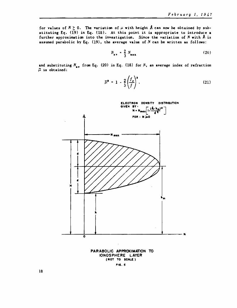
where h. and d are the height of maximum ionization and the semi thickness of the approximating parabola respectively. These terms are illustrated in Fig. 5 where the equation for the electron density distribution IS:
(19)
17
February 1, 194.7
for values of N ~ O. The Tariation of ~ with height A can now be obtained by substituting Eq. (19) in Eq. (18). At this point it is appropriate to introduce a further approximation into the investigation. Since the variation of N with A is assumed parabolic by Eq. (19), the average value of N can be written as follows:
N a£N a. 3 max
(20)
and substituting Na• from Eq. (20) in Eq. (18) for N, an average index of refraction jl is obtained:
18
p' • 1 • ~ G'), ELECTRON DENSITY DISTRI8UTlON
GIYEN IY. r: (.t- hili)· ] N • NlIMIlI~- '""'1T FOR I N ... O .
.... -----N III .. ---,-----...-j
H
-~--~O--L----------------~----N
PAR ABOLIC APPROXIMATION TO IONOSPHERE LAYER
(NOT TO SCALE)
FIG. 5
(21)

February 1, 1947
In setting up an equatorial model of the iooosphere from which to calculate the refraction of radio waves shorter than five meters, the 'slab approximation' is used. In other words the parabolic Fa layer is replaced, for calculations, by a layer of constant refractive index ~ given by Eq. (21) having a lower surface at height h = h. - d, and an upper surface at height H z h. + d.
To calculate the refraction 8' produced by the slab approximation consider Fig. 6. The path of a typical ray has been drawn as a continuous line, and the various auxiliary angular parameters are labelled. The scale is exaggerated for clarity, Snell's Law for point P states that:
The law of sines applied to triangle CPQ gives:
(a + H) sin cPa = (a + h) sin cPa
and eliminating ¢a from Eqs. (22) and (23),
(a + H) sin ¢1 • ~ (a + h) sin ¢3'
h--..; ..... -----H ------i
GEOMETRY OF REFRACTION IN THE IONOSPHERE (SLAB APPROXIMATION)
(NOT TO SCALIE)
FIG. 15
/ /'
/ /
P. -I
/ " /
(22)
(23)
(24)
19

February 1, 1947
. For point Q Snell'. Law similarly statu:
p. sin ¢, • sin ¢", ' (25)
and from triangle CQO,
(a + h) sin ¢. • a cos 8 • (26)
so that eliminating ¢. from Eqs. (25) and (26),
~(a + h) sin ¢s • a cos 8. (27)
From Eqs. (23), (24), (25), (26). and (27) it i. now possible to write expressions for the four angles ¢ as follows:
..;.. • sin-1[_a_ cos ""1 a + H 8] . (28)
cos 8] . (29)
¢, • sin- 1[ a cos e] . J,J.(a + h)
(30)
¢. • sin-1[a : h cos 8J . (31 )
A To obtain R' note that R' is the angleQTP; therefore. consider expressions for the angles of triangle TQP:
A TQP • ¢. + 180 0
- ¢, •
A QPT. ¢a - ¢1 •
A P TQ. R' •
Now the sum of the angles IS 180 0; hence. adding and solving for R':
If it is assumed that I »Ie' this expression for R' may be satisfactorily approximated by a more useful expression:
20
)
-3/a 2h
+ a· cos 8 . (32)

February 1,1947
This expression for R' is analagous to Eqs. (4) and (14). Fig. 7- is a plot of R' as a function of e for several frequencies between 60 and 1000 megacycles. This plot is for the equatorial model of the Fa layer. By asstllting reasonable equatorial models for the lower daytime layers at local noon, it can be shown with the aid of Eq. (32) that the Fl and E layers contribute to the total refraction at the horizon only about S% and 2% respectively of the refraction caused by the Fa layer.
In general it will be noted that ionospheric refraction is proportional to the layer thickness, and the square of the critical frequency for a particular frequency, and for a particular condition of the layer, it is inversely proportional to the square of the frequency. The refraction is always greatest at the horizon and zero at the zenith. From about 500 megacycles upward it can safely be asserted that refraction by the ionosphere is negligible.
Since the Australian observations of radio wave refraction by the earth's atmosphere lO were made at 200 megacycles it see ... worthwhile to calculate what effect the Fa layer may have had on the ooserved refraction, which as reported was apparently attributed entirely to the lower atmosphere. In the absence of exact dates of observation and simultaneous ionosphere observation, ionosphere observations from Watheroo, Western Australia for April 1946 are usedlS • Remembering that the local time in that part of the Fa layer traversed by the waves from the rising sun is is about 1-1/3 hours later than the local time, sunrise, on the ground, the Watheroo data gives:
Ie • S.S Mcls h • 146 miles
H • 20S miles .
From Eq. (32) for a frequency of 200 megacycles, the value of R' is found to be 1.4 minutes of arc at the horizon. Since the observed values for refraction near
- . The d.t. plotted in Fig. 7.re the reault of the nu_rical e .... lu.tion of the foll09ing integral:
II
J lA - h lcI.A cos e ~i[iA + ala~ a _:a cos a eJ~
H
where from Eq. (18) and in .ccordance with the p.rabolic diatribution of electron density giYeft by Eq. (19),
The d.t. were originally calcul.ted by thia .. ana aa a check on the reli.bility of the .. a lab approxi.ation", aince the inte,ral inyohea no approxi.ationa. Within the limits of accur.cy of earlier" a lab .pproxi.ation" calculations, there were no aignific.nt dif· ferences, .nd it •• y be a.fely atated that for Bloat practic.l purpoaea the "slab .pproximation" ia s Yery ,ood one. Eq. (32) Cont.ina aiaplifyinl .pproxi •• tiona, .nd results calculated from it do not quite asree with the reaulta ahown in Fig. 7 particularly .t lower frequenciea.
21

February 1, 194.7
the horizon showed some scatter but were of. the order of one degree. the refraction contributed by the F. layer can be safely neglected, and the Australian results accepted as reported.
III-B-3. Parallactic Corrections to Refraction
It i. now necessary to point out that all expressions for refraction thus far stated give the bending of the ray path and are therefore the corrections to be subtracted from the apparent angular height of an object at a very great or essentially infinite distance (such as an astronomical object) to obtain the true angular height. When the body observed is a satellite vehicle or guided missile. an additional correction of a parallactic nature must be applied. This correction is a function of the slant range d as observed by a radar.
I11-B-3-.. For Li.,n, GAd Radi.o '.v •• R.!rGC,.d by 'M LOfHr A'lIDapMr.
Fig. 8 will serve to illuatrate the derivation of the parallactic correction for lower atmosphere refraction of both light and radio .aves. S is the satellite at a distance d from the Observing position. It is assumed to be at a height essentially great enough to be considered outside of the effective lower atmosphere. For radio .aves this height can be taken as about 8 miles (only 4 miles at the equator). and for light the height is about 30 miles. From Fig. 8,
where
(33)
1S the refraction given by Eqs. (4) or (14)
is the parallactic correction for an object at a distance or range d,
is the net refraction to be subtracted from the observed value of e to find the correct angular'elevation.
Applying the la. of .ines to triangle aI'S:
(Jf' d (34) sin M • .in(l80o _ R)
but both R and AR are less than 1-1/2 degrees and their sines may be replaced by the angles themaelves. Therefore,
(35)
and hence,
(36)
22

February 1, 194i
50
40
30
20
~ 10 C '.0 ... '.0 07.0 fII '.0 "" !; 5.0 z i4.0
53.0
!2.0
~ II: o c,) 1.0
~ 0.' 0.8 0.7
= 0.' t; 0.5 II:
0.4
0.3
0.2
0.\
~
" ~MC"
" ~ '\
'\. "'- '-
"- " "--.l2.0MCIJ '" '" '"' ~ " '" "- "-~MCII "- "- ~
" ,," "-
'" " , ~ " ,\ '" ~ ~ ~ ~ ~
"'- '- "'- "'- "'-"- " "- "- "-
'" "- "- " '" " '" ~ -.....e..0OMCi'S \. " "- '" '''"-
'" "- "- "- " "-"- "- " ~ " "- ." \
~C" '" " '" '" " , 1\
~ '" ~ " " '" ~ '\ ~\ 20· 30· 40· 50· 60· 70· APMRENT ANGULAR ELEVATION. 8. DEGREES
REFRACTION CORRECTION FOR RADIO FREQUENCIES (APPARENT MINUS TRUE ANGULAR ELEVATION) FOR REFRACTlON CAUSED BY PASSAGE THROUGH THE EQUATORIAL (MODEL) F2 LAYER OF THE IONOSPHERE
FIG. 7
23

February 1, 1947
"af(II»1 LOWER ATMOSPHERE
" • 1 PRE! SPACE
C~--------~--------+---------------~-----------• ----+---- 11 •• ----""1
GEOMETRY OF REFRACTION IN THE LOWER ATMOSPHERE SHOWING THE PARALLACTIC CORRECTION
(NOT TO SCALE I
FIG. a
It will be seen that for very large values of d, Rd approacbes R. It is now necessary t'O find an expression for at. From the modified form of Snell's Law applicable to refraction through concentric spherical layers. as illustrated by Eqs. (24) and (27), the following equation can be written at once:
where ~ = 1 + ~. the index of refraction at the observing station, O. Now consider triangle CPA, by the law of sines:
(J + ho '" ---------- (38)
sin (180 0 - a)
but for triangle ~T, a = 90 0
- e + R
so that
ain 0800 - a) '" COB (8 - R). (39)
24
February 1, 194.7
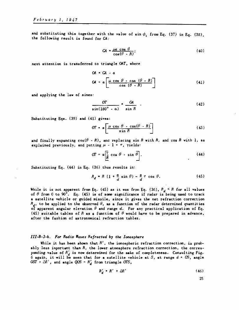
and substituting this together with the value of sin ¢1 from Eq. (37) in Eq. (38), the following result is found for CA:
CA = f..¥l cos 8 . cos(8 • R)'
next attention is transferred to triangle CKT. where
Q4·CA-a
Q4 = a rJ.L cos 8 . cos (8 - R)] L cos (8 - R)
and applying the law of S1nes:
sin(lSO° - a.) sin R
Substituting Eqs. (39) and (41) gives:
ar = a [J.L cos 8 - cos(8 - R)l sin R J
(40)
(41)
(42)
(43 )
and finally expanding cos(8 - R), and replacing sin R with R, and cos R with I, as explained previously, and putting J.L - 1 = T. yields:
ar = alli cos 8 - sin ~. (44)
Substituting Eq. (44) in Eq. (36) thus results in:
Rd = R (1 + ! sin 8) - ! T cos 8. d d
(45)
While it is not apparent from Eq. (45) as it was frpm Eq. ~36), Rd < R for all values of 8 fran 0 to 90°. Eq. (45) is of sane significance if radar is being uaed to track a satellite vehicle or guided missile, since it gives the net refraction correction Rd, to be applied to the observed 8, as a function of the radar determined quantities of apparent angular elevation 8 and range d. For any practical application of Eq. (45) suitable tables of R as a function of 8 would have to be prepared in advance, after the fashion of astronomical refraction tables.
111-B-3-b. For Radio 'avel Refracted by the lono'phere
While it has been shown that R', the ionospheric refraction correction, is probably less important than R, the lower atmosphere refraction correction, the corresponding value of Rd is now determined for the sake of completeness. Consulting Fig. 6 again, it will be seen that for a satellite vehicle at S, at range d z OS, angle OST = 68'. and angle QOS = Rd from triangle OT.S.
R' '" R' + M' d (46)
25

February 1, 1947
and,
Approximating as before:
so that:
From triangle CPA,
but from triangle eMT,
so that,
but from Eqs. (24) and (27),
_...;(Jf'~~ .. __ --=d~-~ sin !::R' sin(lSO°· R')
M' • Uf X R' d
R' • R' (l + Uf) II. d
• a. + H sin(lSOo • a.)
a. • 90° • 8 + R'
sin(lSOo - a.) = cos(8 - R'),
(4 + H) sin ¢1 = a cos 8 •
Substituting Eqs. (51) and (52) in (50) and solving for ~ results in:
CA '" 4 cos 8 . . co.(8 - R') ,
and in analagous fashion to the reasoning for the lower atmosphere,
04·a-~
04 '" 4 [cos (8 - R') -,cos 8l . cos (8 - R) J
Applying the law of sines to triangle 04T:
Q4
sin R' sin( IS0 0 - a.)
Substituting Eq. (51) and solving for Uf gives:
ar '" a rcos(8 - R') - cos 8J . l sin R' J
26
(47)
(48)
(49)
(50)
(51)
(52)
(53)
(54)
(55)
(56)

February 1, 1947
Expanding coste - R') and appraxilll8ting as before. the result is
ar = a sin e (57)
and substituting into Eq. (49) the value of ar from Eq. (57) the result is:
R~ .. R' (1 + S sin e). (58)
It will be seen that this result is in form identical with Eq. (45) if T = 0, and it .. ans that the net ionospheric refraction Rd for a satellite vehicle on orbit at ranse d is greater than the refraction correction R' for an astronomical object. An interesting consequence of Eq. (58) is that the net refraction correction for a satellite vehicle approaching a station at a constant height of say 350 miles (i.e., both aid and sin e increasing) can remain close to the maximum (horizontal) value until the vehicle is well up in the sky. As the vehicle approaches the zenith Rd becomes zero; Fig. 9 is an example of this. If, for reasons still to be demonstrated, the radar frequencies are kept above about 700 megacycles, ionospheric refraction effects can be neglected.
18
/ ~ « " " II
14
~ 12 C " \ '" " ~ 10
., ~ 8
! • I
4
t
o o
\.
\ ~ ~~;'I"OR 100 MC/, 'OR CIRCUL.AR O"IIT AT "0 MIL.ES HEIGHT
'" f-R t 'OR 100 M c/, .", .-ROM Fl •• 1
10
~ ~ -
" " ~ -.... r--- -.............. ----to so 40 so 10 10
APPARE NT ANGUL.AR EL.EVATION,' DEGREES
EXAMPLE OF RELATIONSHIP BETWEEN R' AND R~ (SEE EQ.58) FOR POSSIBLE SATELWTE SITUATION
,. •. e
10
III-C. DISPERSION
eo
In the preceding discussion of refraction in the lower atmosphere, the index of refraction of the air for light ••• assumed to be independent of .avelength. This is not, strictly speaking, correct. The index ~ is slightly greater for the blue end
27

Februa.ry 1, 1947
of the spectrum than for the red, and the air is therefore dispersive. 'The difference is so slight, however, that it does not become noticeable, for example, in the case of the stars until the elevation angle decreases to less than about two degrees. The • green flash' phenomenon at sunset and sunrise is the result of dispersion at the horizon where refraction may differ for red and blue by a minute or more of arc.
For radio waves in the lOWer atmosphere there is no available information to suggest any appreciable dispersion, though as for light waves, it is unwise for several reasons to use ray paths much closer than five degrees to the horizon.
That the ionosphere is dispersive is clearly demonstrated by Eq. (21) which also shows that both dispersion and refraction are less important at very short wavelengths.
An obvious method of eliminating dispersion difficulties is the use of 'monochromatic' radiation. Unfortunately, this procedure is complicated by the use of short sharp pulses in'MOst radar systems. Such pulses have considerable energy in sidebands and the ionospheric dispersion will therefore tend to broaden and soften the pulse form. In a pulse time or pulse position modulation communications system. ionospheric dispersion will have the same effect. In neither the case of radar nor pulse modulation is there any reason to suppose that the effects of dispersion on pulse form will be as great as the effects of the finite bandwidths in the receivers. The dispersive effect of the ionosphere is not further considered at this time.
III-D. DELAY
Range is determined with pulse-radars by observing with very high prec1s1on the time it takes for a minute fraction of the energy of a pulse of radio frequency radiation originated by the radar station to travel out to a target and return after reflection. If d is the distance of the target from the radar station (i.e., the socalled slant range), and v is the velocity (assumed constant for the moment) of propagation of the pulse. the time t taken for pulse energy to travel to the target and return (assuming instantaneous reversal of direction of propagation at the target) is:
so that the range is given by:
d = .1 vt . 2
(59)
(60)
In radar practice,v is taken to be either equal to the velocity of light c, or a value slightly less than the velocity of light intended to represent an average value of the effect of refraction. The use of v • c is strictly correct only when the medium through which the radar pulse travels is free space or a medium having an index of refraction of unity for the radio frequency in use.
By definition the index of refraction ~ of a medium such as air with respect to free space is the ratio of the velocity of propagation in free space c to the velocity of propagation in the medium v. It is customary to think of .free space as having an index of refraction of unity and therefore,
(61 )
28
February 1, 1947
With the aid of Eq. (61) it is possible to calculate the error which will be made in range measurements if the velocity of propagation of the pulse is assumed to be c. Suppose a radar is used to determine the distance of a target through a medium having a constant index of refraction ~ with respect to free space. If d' is the range determined by the radar, then
d' • ! ct 2
(62)
since the particular radar set in use has its range scale calibrated on the assumption that the velocity of propagation is c. Representing the true range by d,
d '" ! vt 2
(63)
and putting the difference d' - d equal to~, the radar will show a range in error by
&l = ! t(c - v) 2
and substituting the value of c from Eq. (61):
&l • ~ - 1) d •
(64)
(65)
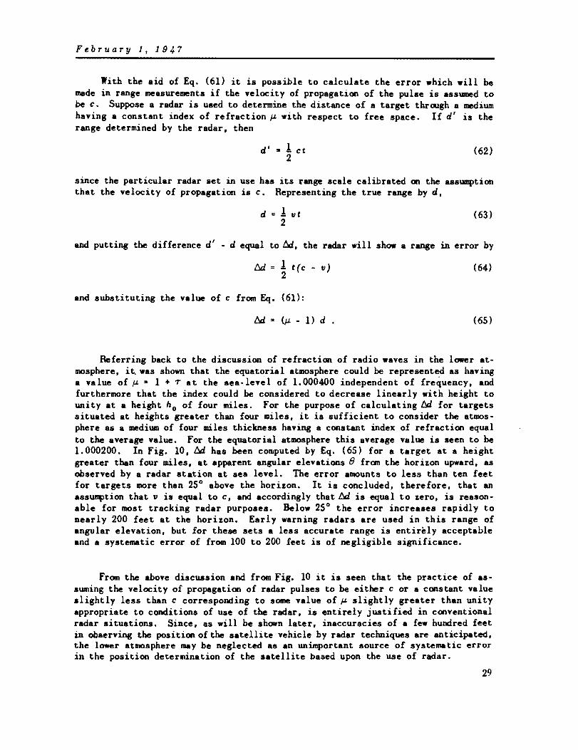
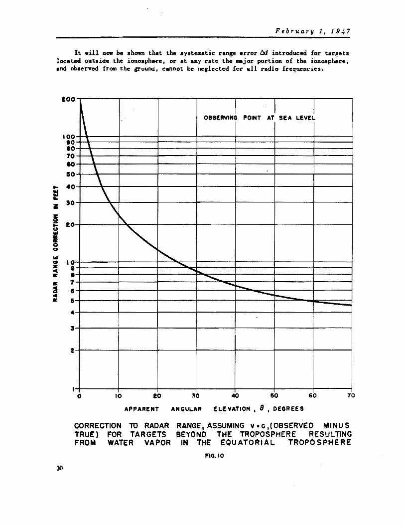
Referring back to the discussion of refraction of radio waves in the lower atmosphere, it, was shown that the equatorial atmosphere could be represented as having a value of ~ • 1 + T at the sea-Iev~l of 1.000400 independent of frequency, and furthermore that the index could be considered to decrease linearly with height to unity at a height no of four miles. For the purpose of calculating ~ for targets situated at heights greater than four miles. it is sufficient to consider the atmosphere as a medium of four miles thickness having a constant index of refraction equal to the average value. For the equatorial atmosphere this average value is seen to be 1.000200. In Fig. 10, 6d has been computed by Eq. (65) for a target at a height greater than four miles, at apparent angular elevations e from the horizon upward. as observed by a radar station at sea level. The error amounts to less than ten feet for targets more than 25° above the horizon. It is concluded. therefore, that an assumption that v is equal to c. and accordingly that 6d is equal to zero. is reasonable for most tracking radar purposes. Below 25° the error increases rapidly to nearly 200 feet at the horizon. Early warning radars are used in this range of angular elevation. but for these sets a less accurate range is entirely acceptable and a systematic error of from 100 to 200 feet is of negligible significance.
From the above discussion and from Fig. 10 it is seen that the practice of assuming the velocity of propagation of radar pulses to be either c or a constant value slightly less than c corresponding to some value of ~ slightly greater than unity appropriate to conditions of use of the radar, is entirely justified in conventional radar situations. Since. as will be shown later, inaccuracies of a few hundred feet in observing the position of the satellite vehicle by radar techniques are anticipated. the lower atmosphere may be neglected as an unimportant source of systematic error in the position determination of the satellite based upon the use of radar.
29
February 1, 191,.7
It .ill DOW be shown that the systematic range error 6d introduced for targets located outside the ionosphere. or at any rate the major portion of the ionosphere, and observed from the ground, cannot be neglected for all radio frequencies.
IOO,--------r------~------~r-------~------~-------r------~
OBSERVINl POINT . A) SEA LEVEl
100~\~-----+------~--------~------+-------~-------+------~ .o~~'-----+------~--------r_------+_------~------_+------~ .o~~\~--~~------r_------~------+_------+_------~------~ TO~-\~----~------~------~-------+------~~------+-------~ .a~-\+----+------~------+-------r-----~~-----+------~ I04-~\~-4------4_----~------~----~------~----~
i .o~~'\~-----~---~---~----+----~---~ • 50 \
I 104-----~~~--_+----~~----+_----~----_r----~ I " : "'--......... G 10~------_+------~--~.~~-+------~--------r-------+-------~ z .~------_+------~----~~r_------~------_r------_+------~ = .~-------+------~-------~~,~~---+--------~------+-------~ II:
= C II:
30
-........ T -8~-------+------~--------~-----~-+~-=~~~~------+-------~ --.... ...... 11-----r---~------_t------~------~~~~~~ -4~-------+------~--------~------~-------r-------+------~
5~------_+------~--------~------~------_r------_+------__
2~------_+------~--------r_------+_------~------_+------~
I~-------+------~--------~------+-------~-------+------~ o 10 10 ~O 50 60 70
APPARENT ANGULAR ELEVATION. 8 • DEGREES
CORRECTION TO RADAR RANGE,ASSUMING v.e,(OBSERVED MINUS TRUE) FOR TARGETS BEYOND THE TROPOSPHERE RESULTING FROM WATER VAPOR IN THE EQUATORIAL TROPOSPHERE
FIG. 10

February 1, 1947
The ionosphere is a very different kind ot" medium from the lower atmosphere. From Eq. (16) it will be seen that the index of refraction of the ionosphere is a function of frequency and that for all frequencies it is less than unity. The pre· vious discussion based on Eq. (61) would thus appear to indicate that v in the ionosphere is greater than c. Now a pulse can be thought of as a wave-packet possessing energy. and for energy to be propagated with a velocity greater than that of light is a violation of special relativity. The difficulty is entirely removed when it is recalled12 that the ionosphere is a dispersive medium for which pulse velocity or group velocity V is related to the phase velocity v by the relationship,
(66)
The index of refraction less than unity must then signify that the phase velocity is greater than c. This does not imply any violation of special relativity since the pulse energy is associated with the group velocity.
Eliminating v in Eq. (66) by substituting the value of v from Eq. (61),
and Eq. (64) for pulses travelling through the ionosphere becomes:
t:J. = 1. t(c - V). 2
Inserting c from Eq. (67) and remembering in this case that
the result 18:
d • .I Ut 2
(67)
(68)
(69)
As for the troposphere an equatorial model of the ionosphere has been used for the earlier determination of refraction. Instead of a parabolic variation of ~ with height, the average value ~ has been used; it is given by Eq. (21). The ionosphere model then consists of a slab of thickness H - h, the lower edge of which is at a height h and which has a constant index of refraction ~ given by Eq. (21) as a function of frequency.
For the moment consider a radar set which is used to observe a target through a series of n different media, each with a constant index of refraction. If ~i is the index of the i tb medium, and d i is the portion of the range in the i tb medium then
d • t:. d. 1
,=1
t:J.. i: t:J. i • ';=1
31

February 1,1947
Now auppoae " .. 4. and the first medium is the troposphere medel. the second free space. the third the ionosphere model. and the fourth free space again. then:
but by Eq. (65)
t:41 .. (p. - 1) d1 # jl for tropospheric air
and since the index of refraction of free space is unity,
I::J. .. t:4 .. 0 a ..
and by Eq. (69)
I::J.s • t1 P. p.) ds' J1. for the ionosphere.
For the satellite vehicle then the range correction will be the sum of ad1 and ada' t:41 has already been calculated. and the result. independent of frequency, is shown in Fig. 10.
To study the radar range error caused by the ionosphere it is first necessary, using the equatorial model and 'slab' approximation, to determine the ionospheric path as a function of apparent angular elevation e of target. Returning to Fig. 6 it will be seen that ds '" QP .. •• In triangle CPQ the angle f1;P .. cPs - cPa' hence by the law of sines:
(70)
but in cmnection with ionospheric refraction it was shown from Eqs. (29) and (30) that
sin cPa .. G cos e jl (G + H)
( 71)
and sin cP, .. a cos e.
jl (a + h) (72)
Expanding Eq. (70) and eliminating cPa and ¢, by using Eqs. (71) and (72). the result after some simplification is:
.. -Jr-"(G-+-H-)-a -.-(-;-c-os-e-)-' .~ (a • h)' • (; cos e) • . (73)
Since Eq. (73) is a function of jl. s must be a function of frequency as well as 8. Fig. 11 has been prepared to show s as a function of e for frequencies of 100, 200, and 10,000 megacycles for the equatorial ionosphere model. It will be seen that at 100 megacycles and upward in frequency the difference between jl and unity has very little effect OD s.
32

February 1, 1947
."
'" .... •
480~--'---.---~--.---r---r-~~~~~
~-IOO~Me/l 460~~~==~~+---+---~--~--~~~~ 1\."' ........ ~200 J Mell
I , -10000 Me/I 440~~H---~--+---+---+---~--~--~~
~ 420~--~~~-4---+---+---+--~--~--~--~
400~--~~~--+---+---+---r---~~r-~
580~--4-~~--+---+---+---r---~--~~
56 0
• 54 0
, • :z: t-o Z
'" ...I
:z: !C Q.
32 0
50 0
28 0
26 0
240
22 0
20 ... ...
18 0
16 0 O·
\ \ ,
\ \
\ \
\
10· 20· 50· 40· 50· 60· 70· 80· 90·
APPARENT ANGULAR ELEVATION, 8, DEGREES
LENGTH OF RAY PATH· IN EQUATORI AL IONOSPHERE MODEL (SLAB APPROXIMATIO~) AS A FUNCTION OF FREQUENCY AND APPARENT ANGULAR ELEVATION OF THE TARGET.
FIG. II
33

February 1,1947
The radar range error caused by the ionosphere 6dJ for a satellite located outside the ionosphere has been plotted in Fig. 12 against radar frequency for several values of observed angular elevation e, from 0 to 90°. It will be seen that this source of systematic error is important when Observi~g the satellite by radar. If frequencies around 100 megacycles are used (typical radar: SCR 270) the range error will be about two miles for elevation angles less than 10°. In order to be able to neglect a systematic error such as the radar range error caused by the ionosphere, the error must be substantially smaller than the inaccuracy from other causes in the quantities determined from the range measurements. From Fig. 12 it is seen that frequencies in excess of 700 megacycles must be used if the radar range error is to be kept under 200 feet at all times. 700 megacycles is thus seen to be the lowest frequency which can be used for the satellite if the radar range error is to be neglected. A practical consequence of using radars at frequencies much below 700 megacycles is the need for making corrections based on simultaneous ionosphere observations or very good predictions. Either of these would at best glve only an approximate ~alue of the correction since ionosphere soundings to determine ~ cannot be made above the height of maximum ionization.
Over the equatorial zone in particular the ionosphere is both thick ~ld highly ionized. In Fig. 12 the curve for e = 90° is of special interest since it gives the systematic corrections to the readings of any pulse type altimeter which might be mounted in the satellite. Even at frequencies as high as 700 megacycles an altimeter would indicate heights some eighty feet too great.
In concluding this discussion of the medium through which the satellite observations are to be made, the following is a summary of the more pertinent facts which have emerged:
34
1. Light waves, provided a sufficiently-intense source is available, can be used for observation, but they are severely limited in value by the opacity of any intervening clouds and suffer considerable attenuation on nearly horizontal ray paths.
2. Radio wave-s shorter than about five meters can be used for communications.
3. Since a radar set is inherently more accurate a~ a range measuring device than as a means of measuring angles (azimuth and angular elevations), it is necessary to use wavelengths shorter than about 40 centimeters to take full advantage of this possible precision in range measuring by avoiding systematic errors of significant magnitude resulting from passage of the radio frequency pulses through the ionosphere.
4. Wavelengths shorter than about 10 centimeters are definitely unsafe to use for either communications or radar observations owing to attenuation difficulties in the lower atmosphere.
5. For any combined radar and telemetering system, the optimum band of useful radio spectrum extends from 10 to about 40 centimeters.
6. As.a general observation about the medium, it seems unwise to design any observation system, utilizing eitner light or radio waves, to be operated under conditions for which the angular elevation of the satellite is less than about 5°. This same limitation will also tend to keep ground reflection effects to a minimum or negligible proportions in any microwave tracking type of radar.

• .... o 2 . ~
600
500
400
300
200
0
0
0
0
....
0 0
o 100 ~ 90 ::::l 80 ~ 70 :: 600
0 0
a:: 50
~ 40 <C( a::
30
0
0
0
20 0
10 0
! I
!
~
~ ~ ~ ~ ~
FOR OBSERVED ANGULAR ELE VATION ,B t
~ r'-,po.. 10. OF RAY PATH
~ ~ ~ Ir t-IO· I i'" ~~~~ ~1/20. ~ t-..... f:= r 3O• ",I"- 50· ~ ~ f 70. ~ ""t.....
~~/~ ~"" ... '<.......~bL
~~.""~~ ~"'L~ ....
~~:-....:::~ ~ ~
~ ~i'r-.... r-::: ~
~ l' r--. ::::~.
I'
~~ ~ ~ ~
~ ~ ~ ~ ~ ~ ~ ~ f'.. ~ r:::~ t--.... I""- I"--. f'" I 2 3 4 5 6 7 8 91 3 4 6 iI!" > , 4 :> 6 7 891 10 100 1000
RANGE CORRECTION IN FEET
RANGE CORRECTION (OBSERVED MINUS TRUE) FOR TARGETS BEYOND THE IONOSPHERE RESULTING FROM GROlP RETARDATION OF RADAR PULSES IN THE EQUATORIAL IONOSPHERE (MODEL)
FIG. 12
10000

February 1, 1947
IV. TECHNIQUES OF OBSERVATION
IV-A. USE OF LIGHT .AVES
It i. at once apparent that the satellite if visible, either naturally, or by virtue of some internal light aource, will not be seen a. an extended object in the .ky. At 350 miles distance, correaponding to a position vertically overhead, the long axis of the vehicle will effectively subtend somewhat less than two seconds of arc. Adequate resolution of an angl~ aa small as this requires moderate optical assistance (as a minimum a 3 to 4 inch telescope). It is furthermore apparent that the chances of aeeing the satellite at night are vastly greater than by day.
Because the satellite, if visible, will look like a movins star amongst the fixed stars or, perhaps, like a distant aircraft carrying a light, which incidentally might move across the sky with a similar angular velocity, it is entirely natural to use the astronomical scale of brightness. This will require some explanation.
The astronomer describes the brightness of an object by a scale of magnitudes, which wa. originally devised by the ancients to clasaify the stars visible to the unaided eye. All the visible stars were divided into six groups or magnitudes - the brightest stars, some twenty in number, were in the first class or of the first magnitude and the faintest group, including stars just on the threshold of perception, were in the sixth class or of the sixth magnitude. With the passage of years it became desirable to establish the magnitude scale more precisely. Since the response of a sense organ like the eye to a stimulus is logarithmic, it is not surprising that the introduction of photometric techniques into astronomical science revealed that a star of magnitude. was about two and a half times brighter than a star of magnitude • + 1. The magnitude scale, it should be noted at the outset, is inverse; i.e. the brighter the object, the smaller the number of its magnitude class. Ultimately, the magnitude scale received precise definition and the brightness ratio of adjacent integral magnitudes was defined aa 2.512. This number seeins at first somewhat arbitrary. It is actually of great convenience since its logarithm to the base 10 is exactly 0.4, and the reciprocal of 0.4 is 2.5 exactly. The ratio 2.512 was, in fact, selected for these very convenient properties.
With the introduction of a more precise magnitude scale, it became customary to measure magnitudes with greater precision. Instead of saying that the North Star (Polaris) was a second magnitude star (i.e. between 1.5 and 2.5 magnitudes), the brightness would be given as magnitude 2.1, and the magnitude scale became decimally subdivided, at first to one decimal place, later to two, and with the most precise measuring techniques of modern times the third decimal place is sometimes used. Incidentally, since objects brighter than the original stars of magnitude class one are sometimes visible, it became necessary to extend the magnitude scale to zero magnitude, and then into the negative magnitudes. With the advent of telescopes and photographic plates, stars much fainter than the faintest visible to the unaided eye were discovered. This necessitated extension of the magnitude scale to higher and higher numbers as fainter and fainter objects were detected. Some examples of the magnitude scale are contained in the following table:e.'8.'7
36

February 1,1947
<l>ject
Sun •
Moon (full) •
Venus (max. brightness)
Earth (seen from Sun) ••
Sirius (brightest star)
Mars (mean opposition)
Table 1
Standard Candle at one kilometer
Polaris (North Star)
Magnitude
-26.72 -12.55 - 4.40
- 3.80
- 1.86
- 1.85 + 0.8
+ 2.1 Pleiades Cluster (av. star) + 4.0
Faintest star visible with unaided eye (approximately). + 6.8
Faintest star visible with 6" telescope (approximately) +13.0
Faintest objects detectable photographically with 10011 telescope (approximately) +21.0
Some comment on the meaning of the term 'brightness' is necessary. Brightness to the eye is a measure of the rate at which the retina receives ~nergy. It is therefore possible to express brightness in terms of watts per square centimeter. Now brightness and magnitude must be a function of color. This matter would needlessly complicate the discussion about to follow, so for the present it will not be discussed. Star light and satellite light will be considered to be 'white' and not unlike sunlight.
The fact that the faintest star visible to the unaided eye is about magnitude ,6.8 means that the eye has a sensitivity similar to a radio antenna-receiver system. While the threshold varies with individuals. using the value of magnitude 6.8 for the faintest star and taking the pupil diameter of a fully dark accOllllllodated eye to be 8 millimeters16 it can be &bown that the eye'sensitivity to sunlight is of the order of 10-15 watts. The analogy between the eye and a radio receiving system can be extended. The retina itself and the optic nerve correspond to the receiver unit. The pupil and lens of the eye correspond to the antenna. which is both directional and of variable gain. The use of binoculars or telescopes iS'equivalent to the use of larger and more directional antenna arrays.
From the definition of magnitude, it will be seen that magnitude differences correspond to power losses or gains, and that there must be a relationship between the scale of magnitudes of the astronomer and decibels of the electrical and radio engineer. This connection can be found as follows:
11 a-
la 2.5l~ (74)
and taking the logarithm of both sides of the equation,
37

February 1, 1947
and therefore:
(75)
where 6a is the magnitude difference, aa - a 1 , between two objects of brightness 11 and I" If 11 and I. now represent the received power of two radio signals, where as IIhme 11 > I •• the decibel COll'"418rison is:
(76)
putting II/I. equal to 100 •• is 5. and the decibel comparison is 20. so that one stellar magnitude equals four decibels. It is necessary to note certain fundamental differences between magnitudes and decibels. Magnitudes are 'units' on a numerical acale, the zero of which can be defined in terms of a standard candle. Decibels, except for yery special usages of the term, are purely comparison units and their scale has no specified zero, unless a specified reference value be considered a zero. Furthermore, the magnitude scale is inverse, whereas the decibel scale is usually used as a direct scale.
The relationship between apparent brightness and distance follows the well-known inyerse square law. If 10 is the brightness of an object at unit di~tance. then at a distance d its brightness I will be:
I 1&_0 • (77)
da
IV-A-I. Natural Visibility
With -the information above it is possible to arrive at some quantitative information about the visibility of the satellite. The calcula.tions and discussion which follow are exploratory aJ!d some simplifying assumptions are made at the outset. The third stage of the rocket is assumed to be circling the earth at a constant height of 350 miles aboye the equator. The flight is to be' stabilized with the nose of the rocket always pointing in the direction of motion; hence. the stage can neyer be viewed from the ground more than about 60° off broadside because of the curvature of the earth. 'IDe broadside projected area of the third stage is about 52 square feet. Seen nose or end on, the projected area of the rocket is about 24 square feet·. In order to ayoid details of the precise aspect of the rocket with respect to an ObserYer and the illuminating sunlight. it is assumed that the third stage can be represented as a diffuse reflecting circular area, illuminated normally, and always broadside to the obseryer. The radius of this circular area is taken as 2 1/2 feet, and it is assumed to haYe a reflecting power, or albedo, equal to that of the earth1
?,
0.29. 8 Albedo may be taken as the ratio of the total quantity of sunlight reflected in all directions by a diffuse reflecting surface to the total quantity of sunlight falling on the surface. The difference between the quantities represents light absorbed (i.e. heating the surface).
• It ahould be noted that clouda and anow haye albedoa of 2 to 3 ti.ea the yalue for tbe earth ao that if care ia ,iYen to the aurface of the aatellite yehicle. it .ay •• 11 b. that it. apparent .a.nitude .ay b. increa •• d by about one .a.nitude aboye (bri,hter) tban thoae about to be calculated.
38

February 1, 1947
Proceeding now to the calculation of the apparent brightness of the satellite when directly overhead and illuminated by sunlight, it is first necessary to compare the angular area of the satellite at 350 miles, with the angular area of the earth as seen from the sun. Since the albedo of both is 0.29, and both are diffuse reflectors, the apparent brightness of each is directly proportional to its angular area. Considering the satellite as a circular area having a radius of 2 1/2 feet, its apparent angular semi-diameter at 350 miles, since there are 206265 seconds of arc in a radian, is
206265 2.5 • 0.279 seconds of arc. 350 x 5280
Now, at the sun, the earth's equatorial semi,diameter is 8.80 seconds of arc. This is just the value, by definition, of the solar parallax. Therefore in accordance with Eq. (75)
~ = 2.5 log ~ 8.802
10----=-~ 0.2792
= 5.0 log 8.80 10 0.279
= 7.50 magnitudes,
but ~ is the difference between the magnitude of the earth as seen from the sun and the magnitude of the satellite in sunlight at 350 miles. Table 1 gives the value of the former as -3.60, therefore the brightness of the satellite is
-3.60 + 7.50 = +3.70 magnitudes.
It is evident from this line of reasoning that the satellite will be plainly visible to the unaided eye against a dark sky. But like a'star of similar brightness it will be quite invisible in daylight without very considerable optical assistance.
The question now arises~ is it possible for the satellite at an orbit height of 350 miles to be illuminated by sunlight and at the same time observed against a dark sky? The answer to this question can be found .by simple trigonometry, together with the astronomical fact that the entire visible sky can be considered free of sunlight when the sun is eighteen or more degrees below the observer's horizon·,17. Consider the case of evening observing times - similar arguments apply to the predawn period.
1. The satellite will experience geometrical sunset when the sun reaches 23.2° below the horizon of an observer directly beneath the satellite.
2. Assuming that extinction begins to decrease the intensity of the sunlight illuminating the satellite when ray paths from the sun to the satellite pass closer than 40 miles from the earth's surface, the illuminating sunlight will begin to weaken when the sun reaches 21.8° below the horizon of an observer directly below the satellite.
39

February 1, 1947
3. At geometrical sunset, negiectinB refraction, the ray path from the sun to the satellite grazes the earth's surface, and the sunlight is therefore subject to absorption amounting to twice the value shown in Fig. 3 for 8 a 0° or about 11 to 12 magnitudes. Judging by the illumination observed on the moon when totally eclipsed, scattering and sunset effects will illuminate the satellite sufficiently to reduce the loss noticeably.
To assist with visibility problems, Fig. 13 has been prepared from Eqs. (75) and (77) to show the variation in apparent brightness or magnitude of the satellite with angular elevation assuming a circular orbit at 350 miles height. Fig. 13 includes the extinction losses of Fig. 3. It shows that at 25° elevation the satellite is 2.0 magnitudes fainter than in the zenith. If the zenith value of 3.70 magnitudes, previously calculated, is used, then at 25° the satellite,will appear of magnitude 5.70. This is well above the visual threshold, and the satellite at this angular height should be plainly visible to a suitably directed unaided eye. The problems of scanning by eye have not yet been examined. Since the satellite revolves from west to east, it should be watched for in the west, in which direction at 25° angular elevation, it would be overhead at a location about 11° of longitude to the west •
• ith these factors in mind consider the problem of finding the length of time each evening during which it will be possible to see the satellite from an equatorial observing site if it reaches a position more than 25° above the western horizon. If an observer commences looking for the satellite in the west at the end of twilight, the sun will be 18° below his horizon. One hour later the earth will have rotated IS° and the sun will then be ISO + 15° or about 33° below his horizon (exactly 33°' below at equinox seasons, somewhat less at other times). At this time at a point 350 miles above the earth some 11° to the westward the sun's rays will begin to weaken as they commence to come within 40 miles of the earth's surface. This can be seen as follows: 11 0 to the west the sun will only be 33° - 11 0
, or 22° below: the horizon. This is the condition previously stated for commencement of serious absorption of sunligh't at the position 350 miles vertically overhead. The satellite, if it has not already been seen by tne observer, must now appear, for if it arrives later, it will find the orbit position 25° above the observer's western horizon in darkness.
This reasoning has demonstrated the existence of a minimum period of one hour beginning at the end of twilight, during which it will be possible to see the satellite, if it reaches a point 25° above the western horizon. Actually, watching can begin some five to ten minutes before the end of twilight if parts of the sky near the zenith or to the east and away from the afterglow of sunset are watched. Since the period of revolution of the satellite with respect to a fixed earth is about 100 minutes, it is apparent that an observer watching during the period just indicated on a random clear evening has a better than even chance of seeing the satellite.
Another pertinent question is as follows: For how long a period of time will the satellite remain visible after it has been detected at say 25° above the western horizon? From the previous reasoning it will be seen at once that the duration of visibility will vary from some maximum, if the satellite is detected just at the end of twilight, to zero if the satellite reaches 25° above the western horizon more than .. n hour after the end of twilight. The decrease in duration of visibility will be linear with time. The only number required therefore i. the value of the maximum duration of visibility. At the end of twilight the sun is 18° below the observer'.
40
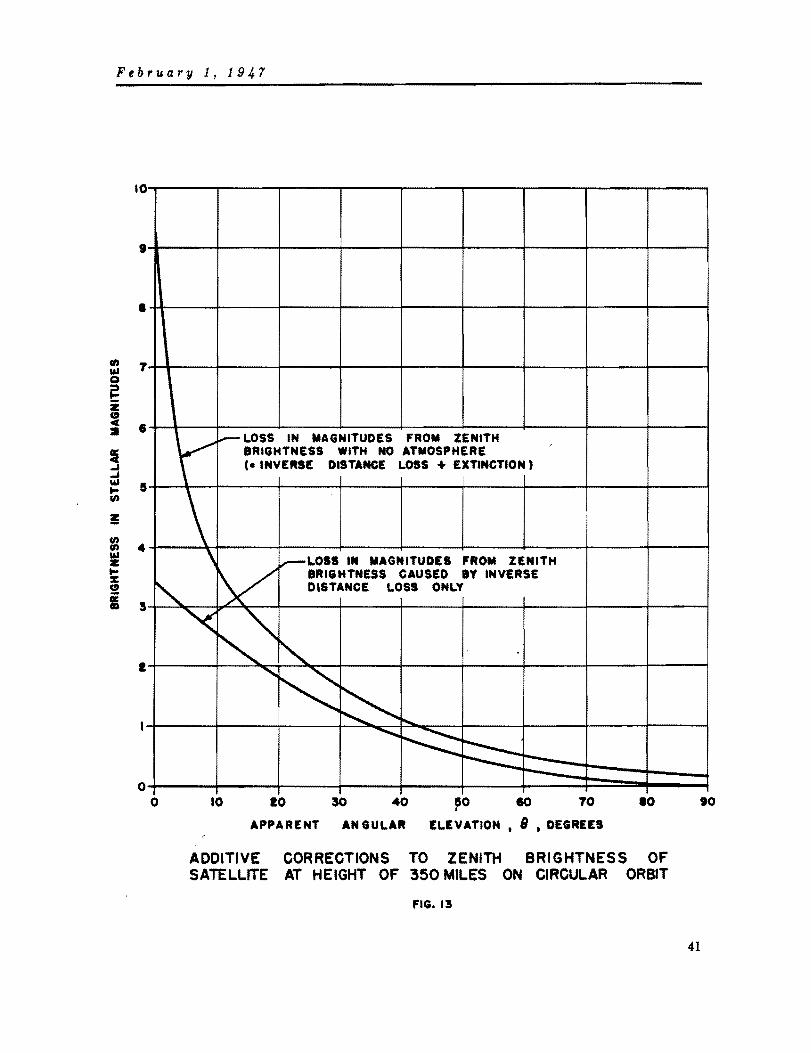
February 1, 1947
10
I
1
., T w
0 e i ~ • • !I ~ ~ w 5 .... ."
Ii ."
4 ." W Z .... % 0
i s
I
o
'(' _ LOSS IN MAGNITUDES FROM ZENITH ,
BRIGHTNESS WITH NO ATMOSPHERE (a INVERSE DISTANGE LOSS + EXTINCTION'
\ \ ....--LOSS IN MAGNITUDES FROM ZENITH
BRIGHTNESS CAUSED BY INVERSE
" V DISTANCE LOSS ONLY
o
'< ",'" "-........
~ ~ ..... .......... ~ :::::::::: ---
to 10 40 50 TO 10 , APPARENT AN GULAR ELEVATION. 8 • DEGREES
ADDITIVE CORRECTIONS TO ZENITH BRIGHTNESS OF SATELLITE AT HEIGHT OF 350 MILES ON CIRCULAR ORBIT
FIG. 13
.0
41

February 1, 1947 ,., western horiEon. Since extinctioa of the illuminating sunlight becomes ser.ioua when the sun is IIIOre than 22° below the horizon pf an observer directly below the satellite. it will be seen, ignoring the relatively slow rotation of the earth, that the satellite will begin to disappear when it passes a positioa some 22° - ISO or 4° of longitude east of the observer. Since the satellite first became visible at a position some 11° of longitude west of the observer, it will be seen that visibility will last for only some 11° + 4° or 15° of motion in longitude. The naximum duration of visibility is, therefore, the time required by the satellite to travel through 15° of langitude; this time is about 4 ainutlts. It is worth pointing out that the satellite will never be visible in the evening at elevations less than about 50° above the eastern horizon. since this is the apparent angular elevation corresponding to an orbital position 4° of longitude to the east of the observer. Cloud banks, mountains, or other obstructions to the east of an observing station will not hamper evening observations.
~ a final comment on natural visibility, it is perhaps worth-while to point out that the satellite when fairly high in the observer's sky will require little more than 20 sltcond. to fade from view once it has passed in the evening the ground position at which the sun is 21.8° below the horizon. Nearer the horizon, the satellite will be lost from view even more rapidly, since it will not need to fade as much to reach the threshold of visibility. The number, 20 seconds, is arrived at by remembering, ignoring rotatioa of the earth, that the satellite has only to move from a position at which the SUD i. 21.8° below the horizon of an observer vertically below. to a position where the sun is somewhat less than 23.2° below a similar horizon. To travel through 23.2° - 21.8° or 1.4° of longitude requires only about 20 seconds, at the orbital angular velocity of 1° in about 16 seconds.
IV-A-2. Vi.ibility of Lu.inous COatings
It is seen from the preceding discussion that the total time available at a single station for optical observations of the naturally visible satellite is severely limited. However, sunlight at a height of 350 miles is very rich in ultra-violet light, and it has been suggested that the duration of natural visibility may be extended by painting the skin of the satellite with a phosphorescent ~oating. Provided that the glow is strong enough and fades slowly enough to prevent the light loss ~ from exceeding ten magnitudes· for the first few minutes after the satellite passes into the earth's full shadow. and further provided that a telescope of moderate aperture, say twenty inches or over. is directed on the satellite .hillt it is still in thlt sunlight (i.e. during an evening observing period), it should be possible to track the satellite for a considerable dist.ance into the earth's shadow.
An alternative proposal is to use a paint which is luminous because of some radioactive ingredient. For example. using a zinc sulphide base, a brightness of 300 microlamberts has been attained using 1.8 millicuries of polonium per square centimeter of surfacell • The skin area of the third rocket stage is about 105,000 square centimeters· and about 190 curies of polonium would therefore be required to paint this surface. In Section VU-C below it is shown that one curie of polonium corresponds to a mass of 0.22 milligrams. The requirement of 190 curies to paint the skin surface can therdfore be translated into a requirement for 42 milligrams of
• A teD .a,Ditude li,ht 10 •• i. equal to a reduction in aurface bri,htnea. by a factor of 100., and repreaenta the eo_pari.on between a diffuae reflectinl .urface exyo.ed to full aunlisht and the aame aurface expoaed to an i.otropie li,bt .ource 0 one candle-power at a diatance of about one and a half feet.
42

February 1, 1947
polonium. A satellite surface brightness of 300 microlamberts. if successfully obtained. will hold the light loss ~ to less than nine magnitudes when the satellite enters the earth's shadow.
It is to be emphaaized that use of either phosphorescent or luminous paint is unlikely to extend the predawn duration of visibility, since the surface brightnesses attainable are insufficient to permit the satellite to be detected initially when it is in the earth's shadow.
IV-A-3. Vi.ibility of a Satellite-borne Light
It bas been shown that there is a period from one hour alter the end of twilight to one hour before dawn each night, when there is no possibility of seeing the satellite vehicle by re(lected sunlight. During this period of some seven and a half hours duration at an equatorial atation, the satellite will pass overhead several timea and be in total eclipse. On these occasions a satellite-borne light, if sufficiently strong. can be uaed to permit observation.
In order to determine the order of agnitude of the intensity of the light source required. it is first necessary to establish a conversion between a standard candle and the scale of IIBgnitudes. A figure inmediately available l," and shown in Table 1 is that a standard candle. at a distance of one kilometer is of magnitude +0.8. From Eqs. (75) and (77) it is a simple IIBtter to convert this value into the IIBgnitude at one mile. Since one mile equals 1.609 kilometers.
2.51zO- = 1.6098
~ = 5.0 loglo 1.609
~ '" 1.03
but the desired quantity is +0.8 + ~. or magnitude + 1.8. Now ignoring extinction for the time being, and noting that an increase by a factor of 10 in distance corresponds to a ~ of 5 magnitudes and that an increase by a factor of 10 in intensity or candle-power for a fixed distance corresponds to a ~ of 2.5 magnitudes. the following table has been prepared.
Table 2
Distance Source intensity
10cp - 100cp 1000cp 10000cp 100000cp
'lea mag IIBg III8g mag mag
1 - 0.7 - 3.2 - 5.7 - 8.2 -10.7
10 + 4.3 + 1.8 I - 0.7 - 3.2 - 5.7
100 + 9.3 + 6.8 + 4.3 + 1.8 - 0.7 1000 +14.3 +11.8 + 9.3 + 6.8 + 4.3
10000 +19.3 +16.8 +14.3 +11.8 + 9.3
43

February 1, 1947
It is a relatively simple matter to determine the value of 6a which must be added to the magnitudes in the line for the distance of 100 miles to obtain the magnitudes for a distance of 350 miles. For a factor increase in distance of 3.5, the decrease in brightness A. is obtained from Eqs. (75) and (77),
2.51ze. ,. 3.52
6a ,. 5 10glo 3.5
6a"'" 2.7.
Combining this result with the data of Table 2, it i, seen that a 10,000 cp light source will appear, at 350 miles, of magnitude + 1.8 + 2.7 or +4.5, which is only about half as bright as the sunlit satellite at the same distance. When it is remembered that ordinary vacuum tungsten incandescent lights have an intensity of about one candle-power per watt, the problem of using an artificial light source of useful intensity and at the same time which consumes a quantity of power within reach of the auxiliary power supply seems incapable of solution.
There are three possible ways in which this apparently hopeless situation can be improved.
1. Use of' light sources of greater luminous efficiency.
2. Use of reflectors. (Table 2 is based on isotropic radiation)
3. Use of intermittent or flashing light sources with a resulting reduction 1n average power consumption.
These points will now be discussed 1n turn. The ultimate gain to be achieVed from the use of light sources of greater luminous efficiency is at best of t}~ order of six or seven times the efficiency of the incandescent bulb. The use of reflectors will lead to gains of four or five over an isotropic source, such as those implied in Table 2. It is possible to obtain much greater gains, but higher gains are not likely to be of much use, since the light to be useful must be visible not only when the satellite is in one position, such as overhead, but also as the satellite approaches and recedes from view.
It is the third possibility enumerated above which seems to offer the only real promise. In connection with stroboscopic photography much knowledge has been obtained about very intense light sources giving very short flashes of light. The sources are mostly high pressure arcs, fired by a Sudden condenser type of discharge. This type of light source is now finding application in commercial photography and sources are now beginning to appear commercially on the market.
A light source of this type advertised- for photographic purposes 1S claimed to have the following characteristics:
44
peak flash
lifetime
duration of peaks
no. of flashes (lifetime)
1. 2 )( 107 lumens
1.8 )( 10· lumen-seconds
1/1250 of a second
30,000.

February 1, 19J,,7
It is to be noted that the lumen is a power unit and is defined in such a IIBnner that the total lUminous flux from a source of unit candle-power which radiates equally in all directions is 4rr lumens. The lumen is therefore a rate of flow of energy. The luminous efficiency of the light source described above is not stated, but it is probably safe to assume that the source radiates at least 50 lumens per watt or has an intensity of about 4 cp per watt.
It must at this point Le decided how frequently the light source must flash. A rate as high as 16 to 20 flashes per second would look like a steady light owing to the retinal persistence <as noted with motion pictures). On the other hand a flash every 5 or 10 seconds would IIBke the satellite ha~d to find. The optimum flashing rate for quick detection during scanning is obviously a complex matter - depending, it is supposed. on such things as duration of flash. color of flash, apparent brightness at peak of flash, and nature of background. For the time being it will be assumed that two flashes per second is about the correct rate. The satellite would certainly be readily distinguishable from the fixed stars if it flashed at this rate, and the average radiation from the source previously described will be:
avo lumens ., 1.2 )( lOT )( 2 = 1. 9 )( 10 •• 1250
With an assumed luminous efficiency of 50 lumens per watt, the
av power = 1.9 )( 10· = 360 watts • 50 •
Assuming 10 watts are available for making light flashes having the duration of the t
source described above and flashing at the same rate, it is seen that the peak flash can only be:
1.2 )( lOT z 3.1 )( 106 lumens 36
provided the IWllinous efficiency is 50 lumens per watt. Remembering that an isotropic source of one candle power emits 417 lumens, it is seen that the peak flash available from 10 watts average power is:
3.1 )( 106
a 2.5 )( 10· candle-power. 417
It is thus apparent that a source of this kind to give peak flashes equivalent in brightness to the continuous reflected sunlight would require from 15 to 20 watts average power even using reflectors.
This apparently somewhat promising result gets into trouble when it is recalled that the eye has a time constant or action time for its response to very weak light of about 0.2 secondsll • A somewhat crude way of considering this is as follows. For each step of the magnitude scale, there corresponds for the eye a certain number of quanta of light per flash which muat go into the retinal image. If the eye receives less than this it cannot respond. For times less than 0.2 of a second, the response
45

February I, 1947
can be considered, according to Bloch's Law, roughly proportional to the time. Since the flashes of the above proposed source are only 1/1250 or 0.0008 seconds long, it will be seen that the flashing source will appear fainter by an approximate amount
2.51~. '" 0.20 0.0008
6a • 2.5 log10 250
6a '" 6.0
than a continuous light source of the same intensity as the peak flash. In other words, a flashing light source operating at a rate of two 1/1250 second flashes per second would have to show peak flashes corresponding to an average power consumption of about four kilowatts in order to appear as bright as the sunlit satellite.
Since little more than 10 watts of continuous power are likely to be available for a satellite-borne light, about the only use for such a light would be to extend the duration of the evening tracking period in the manner suggested above in connection with the discussion of luminous coatings. From Table 2 it is seen that a 10 candle-power light, particularly if reflectors are used, will keep the light loss ~ less than 10 magnitudes when the satellite passes into the earth's shadow.
To summarize the visibility discussions above, it has been shown that:
1. The satellite will be visible to the unaided eye when illuminated by sunlight and viewed against a dark sky.
2. A single observing station has a better than even chance of seeing the satellite on any random evening during the period fran just before the end of twi. light to about one hour after the end of twilight. Similar condi tions exist before dawn. Hence, a few observing stations scattered around the world at locations where clouds are not an unduly serious problem will yield observation points on every revolution.
3. The satellite may be tracked into the earth's shadow with the aid of a telescope of moderate aperture if it is coated with a luminous material or if it carries a light of about 10 candle-power or more.
4. The possibility of mounting a light on the satellite of sufficient intensity to be useful for initial detection seems unlikely. Use of a flashing light, with a rate of two flashes per second, and the most efficient flash duration of about 0.2 seconds {shorter flashes would require balancing increases of peak intensity to produce comparable sensation} will allow the average power required to be dropped to about 0.4 that needed for a continuous light source. Even then something of the order of four kilowatts will be required to produce a brightness of the same order as that resulting from the natural visibility of the satellite in the sunlight.
The principal discussion so far has deliberately emphasized unaided eye ViSlbility, since the unaided eye is about as efficient a scanning device as is available for large areas of the sky. Once even crude predictions are available to narrow the region of the sky which a particular observer will need to scan, then optical assist-
46

F.ebruar1l 1,1947
aDCe is ..... eful. Ordinary 7 x 5C binoculars baying a field of view about 7° indiameter and shOwing stars down to about magnitude 10.5 would prove very uaeful in permitt ing the satellite to be first observed some five degrees above the horizon and thereby extending the maximum duration of natural visibility to some seven minutes. Such a pair of binoculars is practically identical in properties to a 'richest field teleacope,ao of two inch aperture. Greater optical assistance implies smaller angular field of view, and it may well be that 7° is too restricted a field for earliest detection. At any rate, once the satellite is detected, by whatever means, it may be optically followed or tracked. Given suitable base lines and good time measureJents very good positions should be obtainable by triangulation. During the periods of visibility at radar obsening stations the performance of radar tracking may easily be checked.
The matter of daytime visibility has not been discuased. Considerable optical aid will be required and the rapid motion together with the reduced contrast between sky and satellite combine to make search detection all but impossible. Radar-assisted search might just succeed in locating the satellite. During launching, of course, the jets will make the rocket visible to ground stations for the first few hundred miles or so of flight, and optical tracking can certainly be performed. Experience at present being gained with V-2 firings will undoubtedly supply any necessary information.
IV-B. USE OF RADIO WAVES While many tracking and navigational systems of great accuracy and dependability
utilizing radio waves have been developed during the past few years, none can be used unmodified for satellite observation because of the extreme ranges anQ velocities involved or because the flight path extends above the ionosphere. Hence, a careful study of all systems is necessary to determine which can be modified to meet satellite tracking requirements with the least demand upon technological development.
The following items are of importance in satellite observation and will be studied in the remainder of this section:
1. Radar modulation methods WIling direct echo, corner reflector echo, or beacon response.
a. Pulse radar b. Continuous- wave radar c. Frequency modulation radar d. Phase-shift or tone modulation radar
2. Position finding by radar methods
a. One ground station b. One ground station and satellite-borne altimeter c. Two ground stations d. Three ground stations
3. Position finding by ground analysis of satellite signals
a. Hyperbolic systems b. Relative velocity systems c. Radio relay systems d. Radio direction finders
47

February 1, 1947
IV-B-!. R8dar Radar may be defined .. the applicatioo of radio principles and techniques to
the detection of the presence of objects and the determination of their rang~s (or velocities) and direction. Two types of radar, search and tracking, are of interest in satellite observation. Search radar is used primarily for providing an early warning of the presence of targets over a large area (or volume), to keep track of later movements, and to give a continuous indication of their bearings and positions. Conventional search radars have an inaccuracy of approximately ± 1/2 mile in range and ± 1/2 0 in azimuth (elevation can only be approximated) at ranges as great as several hundred miles. Tracking radar gives an accurate indication of range, azimuth, and elevation of a single target. Since tracking radar has been used for fire control, ranges of present day equipment extend to only about twenty miles. Inaccuracies of conventional tracking radar syste_ are of the order of ± 0.01 miles in range and ± 0.1 0 in elevation and azimuth. Range and angular rates found by averaging readings over a period of two seconds have inaccuracies of approximately ± 0.003 miles per second and ± 0.02 degrees per second, respectively.
IV-B-1-a. Rad4r Range EqUAtion
The maximum range of a radar system h .. received cODaiderahle discussion i.u previous RAND publications' and e1sewherea , and only a brief consideration of the subject will be given here. Since frequencies below about 700 megacycles have been shown in Section III-D to introduce significant range errors because of passage through the ionosphere and frequencies above 3000 megacycles experience large absorption losses 10 the lower atmosphere, only 1000 and 3000 megacycle operation will be considered.
The basic radar range equation 1S
where
48
d = Maximum reliable radar range
p a Transmitter power output
~ = Effective target area
A ,. Wavelength
(78)
A ,. Antenna area (assuming same antenna for transmitting and receiving)
G = Antenna gain over an isotropic radiator
f z Constant (approximately 0.6 for a parabolic antenna) 1n the antenna gain equation, G .. 41rfA/Aa
S. Minimum detectable signal IIlD

February I, 1947
where
v = Required signal-to-noise ratio
Nf = Noise factor of receiver
10 at 1000 megacycles and 32 at 3000 megacycles
K = Boltzmann's constant
T ; Absolute temperature
L Loss factor ~ 0.6
B = Receiver bandwidth.
Maximum range is a somewhat nebulous quantity since the field intensity of the reflected signal from the same target can vary considerably from time to time under apparently identical operating conditions. This is due primarily to great variations in the amount of radio frequency energy returned to the receiver by reflection from the target with slight variations in target aspect. Before too much faith is placed in the values obtained from the range equation, the effective target area as a function of aspect of the target being considered (or a properly scaled model) should be found experimentally by comparison of reflections with a target of known effective area, such as a corner reflector. Target directional patterns are multi lobed (similar to patterns of antennas several wavelengths long), and considerable variation in calculated range is possible depending on whether a minimum, maximum, or average effective area is used in the range equation. If the effective area of a t~rget is not known it is usually assumed to be the minimum cross sectional area. Interaction of direct and ground reflected waves is another cause of considerable variations in apparent maximum range with slight elevation angle changes. These variations are fairly amenable to theoretical calculation given adequate information about antenna patterns and sites. The range equation, as a means of studying the effect of varying radar characteristics, such as power, modulation, and antenna area, is of considerable value.
~dinarily the gain of an antenna over an isotropic radiator must be kept below approximately 10,000 in search radars. The beamwidth of an antenna is inversely proportional to the square-root of the gain of the antenna and increasing the gain above 10,000 makes the beamwidth too narrow for conventional search techniques. However, search radar will be used for locating the satellite on its orbit, when its position can be sufficiently well estimated that a sector only 50 wide need be scanned. A minimum beamwidth, BWmiD , of only 1/20 is required and, therefore, the maximum gain is given by
2.8 x 10'" G •• x • ( ~ a = 11.2 x 10 .... BW .
IUD
(79)
This value will not be exceeded with the frequencies and antennas to be considered. Hence, the range equation can be used with antenna area a variable instead of being restricted to that value giving a maximum permissab1e gain, as has been done elsewhereal for operation above 1000 megacycles.
Putting parameters into convenient units,
d .. 42D ~,--;;- miles V~
(80)
49

February 1, 1947
with u in square feet, A in centimeters, P 1n megawatts, B 1D megacycles, and D (the diameter of a parabolic antenna) in feet.
Assuming the effective cross section area of the satellite to be 10 square feet (an-2bject of conical shape has poor reflecting properties) and putting in the values of NF for 30 and 10 centimeter operation, the range equation becomes
d(A • 30 em) .. 7.6DV'fi miles (81)
d(A = 10 em) • 10D~ miles. (82)
It can be shown that the relationship between the altitude h, slant range d, and the elevation angle B, of a satellite is given by
+ 2 ~ (83 ) a
where a is the radius of the earth in the same units as d and h. This equation is plotted in Fig. 14 for several values of B. Since Eq. (83) applies to line-of-sight propagation, radar ranges under standard temperature and pressure conditions will be slightly greater. If the elevation angle is restricted to values greater than 5° (for reasons mentioned previously) and the expected altitude is 350 miles, Fig. 14 shows that a radar range of 1400 miles is desired.
IV-B-1-b. Radar Modulation S"teas
Pulse Radar
Pulse radar transmits radio frequency energy in short pulses and determines range by measuring the time elapsed between the transmission and reception of the pulse reflected back by the target. Since radio waves at the earth's surface travel 0.1862 miles in one microsecond, the range is given by
d = 0.1862 t/2 2 0.0931 t miles (84)
where t is the time in microseconds between the transmitted and reflected pulses. Pulse matching by visually superimposing pulses of equal amplitudes can be done at good signal-to-noise ratios to a precision of about one per cent of the pulse length of pulses longer than one microsecond. If pulse amplitudes are not equal, precision is reduced to about ten per cent of pulse length. Since there must be 50 or 60 cycles of radio frequency per pulse, the ultimate accuracy of pulse systems is approximately half a wavelength. However, present techniques yield time difference measurements with a minimum inaccuracy of ± 0.01 microseconds, which corresponds to a range error of approximately ± 0.001 miles. Additional errors increase the range error to about ± 0.01 miles for conventional systems ranging on a IlOving target.
so

February 1, 194,7
2800~--~---r--~--~------~~--~--~---
260~--~~--~--+---~--4---~--~--~--~
2400~---r--~---+---4--~----~-'+---~~ ELEVATION
2200~---r---r---+---+--~~~~--~~+-~
2000~---r--~---+---+--~----~--+-~~~
1800~--~---+---+-+.A--~~--~~+-~4-~ en ~ 2 160~----~--~--~+-~~4-~~~~---+--~
Z
~ 1400~---r--~~-+-#~~L4~~~--+---~~
z cl II:
!Z cl ~ IOO~r---++--~~H-~~--~~~---+-7~--~
PATH OF ROCKET AT 3eo MILE ALTITUDE
o 100 200 300 400 eoo 600 700 800 900
ALTITUDE IN MILES
SLANT RANGE. AS A FUNCTION OF ALTITUDE AND ELEVATION ANGLE FOR LINE-OF-SIGHT PROPAGATION
FIG. 14
51

FebruarY,l, 1947
In uaing the range equation the relationship between pulse width T (in micro.ecands), repetition frequency F (in cycles per second), 8, and V a. given by Haeff22 for search radar can be used, yielding for the maximum search range d"
!P c~or73 8
miles + .If T8
(85)
41' miles. (86)
lr (l~O) l/S 8 +-T8 .
If there is to be no range a..,iguity, the minimum' pulse repet1t1on frequency F. i ", 1S limited by the length of the sweep plus recovery time, so that
(87)
For ease of calculation assU112 F is 200 pulses per second and permit range ambiguity to exist if d, is greater than about 400 miles. Optimum conditions exist when 8 in megacycles equals the reciprocal of T in microseconds, but to allow for frequency drift and the Doppler effect, 8 will be considered twice the optimum value. Under such conditions,
d - 6.2D..,.·r;; miles '(A-30c.) V" (88)
d .. 8.1D ~ r;; miles '(,\ - 10 c.) V~'
(89)
with the peak. power in megawatts and pulse width in micro·seconds.
The above equations are for search radar techniques. The greater accuracy of tracking radar is obtained at the expense of a reduction in range. Because of antennaaxis tilt and a necessary signal-to-noise ratio of abou~ 12, tracking ranges are approximately 45% of the values obtainable with the same equipment operating with search techniques. Hence, tracking range d t is given by
d - 2.8 D y;;- miles (90) t (,\ • 30 c.)
d = 3.6 D ~ miles. ( 91) t (,\ • 10 c.)
Eq. (91) is plotted in Fig. 15.
The satellite orbit lies in a region where drag is negligible ann it should be possible to extend a corner reflector to increase the effective area of the satellite
52

1000
c I ~
.... III
5 II:
i 100
l ~ 2 )(
'" 2
------~ ..
------------~
10 0.1
.. I-- r-
---~ r- I-~~
p.~;!.--- l-
O~ ~~ ---I---l- i- ~ ~ :.-
~ .....-
tP f '!.:- ..-f0-- O·~ r- r--
--- ..-- -r--~ ----I-- i-""~
V ..-O·~~ ..-
---- --I"""" ~ - ---------.... ~ r- I- ~I--"'" -I- O·~r- I--I-.. __ ..
r""" ...-..-----V
1--------~ ..... V ~
f-""
~ V
1.0 10 PULSE POWER II PULSE LENGTH IN MEGAWATT - MICROSECONDS lOR WATT - SECONDS)
MAXIMUM TRACKING RANGE FOR IO-CM RADAR ON A IOSQ.FT. TARGET fiG. 15
~ 1-1-'
~ t-'"
I-.... 1-'
I---~
r""" r-r'"
---~
r""" f- ~
!--r--
100

February 1, 1947
without creating significant aerodynamic or structural problems. The effective area of a corner reflector crr is
cr '" IS 600 L· IA a ( 92 ) r' ,
where L is the length of a side of the reflector in feet and A is the wavelength in centimeters. Relating the range for a corner reflector target dr to the value for a satellite target do.
(93)
d .. 2.0 L do. r(A '" 10 elld
(94)
The SCR·S84. the most readily available 10 centimeter tracking system, has the following characteristics:
P .:: 0.3 megawatts
T ,. 0.8 microseconds
D .:: 6 feet.
Table 3
THE EFFECT OF VARYING PARAMETERS OF THE SCR-584
Maximum Tracking Range in Miles (S-Band) Radar Specifications
Target Area Corner Reflectors
-T P D
fel 10 fta fta L '" 0.5 ft L .. 1.0 ft L .. 2.0 ft 2 50
in f.LSec in Mw in ft cr ,. ·10 fta cr'" 150 ft2 cr" 2400 fta
0.8 0.3 6 10 15 23 15 30 60 5 0.3 6 16 24 36 24 48 96 5 1 6 21 32 48 32 64 128 5 3 6 30 45 67 45 90 180 5 10 6 40 60 90 60 120 240 5 3 10 SO 7'i 110 75 150 300 5 10 10 67 100 150 100 200 400 5 3 20 100 150 220 150 300 600 5 10 20 135 200 300 200 400 800 5 3 40 200 300 450 300 600 1200 5 10 40 270 400 600 400 800 1600
Fig. 15 shows that the maximum reliable tracking range of the SCR-584 on the satellite would be only 15 miles. Table 3 illustrates the effect on the SCR-584 tracking range of varyingP. r, and D with different si1e targets and corner reflectors. It
54

February 1, 191,.7
appears that while echo tracking over the desired range of 1400 miles will not be possible even with the extreme values of the parameters shown in the bottom row, an adequate range can be obtained with a two-foot corner reflector. Table 3 does not consider any decrease relative to the present value of 32 in the noise figure of 10 cm receivers, but it is not anticipated that any great improvement is imminent.
The maximum range may be increased greatly by the use of a beacon responder in the satellite. The range of a radar beacon system may be limited either by the beacon output or sensitivity. Conventional radar beacons, such as the 'Rosebud' (AN/APN-14>, have limited sensitivities of the order of 5 x 10- 8 watts23
• tith such beacon receivers the tracking range db' as limited by beacon sensitivity, is given by
(95)
where D is the ground radar antenna diameter in feet and P is the ground peak power in megawatts·. This and subsequent beacon equations assume a loss factor of four decibels and a half-wave dipole anteMa on the satellite at a tilt of 80 0 from broadside with respect to the ground radar. If the sensitivity of the beacon receiver is increased to make the signal-to-noise ratio the limiting factor, the maximum range d. will be
(96)
where PT is the smaller of the ground radar and beacon values. Power and weight limitations usually require that the value of PT for the beacon be the smaller. Fig. 16 shows the range for 10 centimeter operation. A 30 centimeter system would have a range 80% greater.
'Rosebud' has a peak power of 7S watts and a pulse length of 0.7 microseconds at 10 centimeters23
• Hence,
d~ (Rosebud) = 28 D miles. (97)
Fig. 17 shows the range of 'Rosebud' as a function of ground radar peak power. The ranges indicated may seem surprisingly high in view of the smaller ranges obtained in practice, but it must be remembered that previous long-range observations were on aircraft limited to altitudes of about seven miles and seen practically on the horizon where earth curvature and ground effects severely diminish the received signals. The great altitUdes to be att.ined by the satellite will permit long-range observation
• This and subsequent beacon formula
equations are baaed
d f,A, b 47tS
min
on the funda.ental trans.ission
where Gt ia the gain of the trana.itting antenna and Ar ia the effectiye area of the receiying antenna. This formula ia for free-apace propagation and neglects any
ground lossea.
55

Februa.ry 1,194.7
at hish eleYation angles, for which the free-space propagation equation is applicable. From Fig. 17 it is seen that there is no advantage in increasing ground power above O.S IJIegawatts since range above that value is limited by the beacon transmitter power rather than receiver sensitivity. To obtain a range exceeding 1000 miles with the SCR-S84, the sensitivity of the beacon must be increased by a factor of 34 and the Pr of the beacon transmitter increased to 2700 watt-microseconds. Alternatively, the beacon _y be used unchanged if a 40- foot diameter groWld antenna is used and the peak power of the saR-S84 is increased to O.S megawatts in which case a maximum range of 1100 miles can be obtained.
Cont inuous Wave Radar
Continuous wave radar takes advantage of the Doppler effect to detect a target. A signal of frequency f radiated from a fixed source and reflected back by a target moving with a relative velocity v has an apparent frequency fr given by
f • f + f ~ + (f + f ~) ~ ~ (1 + 2 ~) f r e e c c',
(98)
where c is the yelocity of light in the same units as v and v is positive for target motion towards the fixed source. If the reflected signal and a portion of the transmitted signal are heterodyned. a beat frequency 6f results. given by
bence.
where A. • elf.
Ivl. c 6f = A. 6f 2T -2-
(99)
(lOO)
For greatest sensitiYity {greatest beat frequency change per unit of radial velocity change. i.e., 6flv a maximum}, the carrier frequency should be as high as practical. The bandwidth of the receiver must be great enough to permit simultaneous reception of the frequency corresponding to the maximum relative velocity and the transmitter frequency unless the returned frequency is to be separately received and tracked.- Hence,
B • 'lAf = 0.644 I v~ax I megacycles (101)
with v in miles per second and A. in centimeters. Assuming a signal-to-noise .ax ratio of unity is sufficient, the Doppler range dD on a 10 sq ft target is given by
d · 0.63 DVr PD mile. D(A .. 30 c.} IV.axl (102)
miles (103)
with v.ax 1n miles per second and the continuous transmitter power PD in watts.
• S.para~e ~racking would ~.rlDit u •• of ~ery narrow recei~.r bandwid~h. wi~h conaequen~ reduction of ~h. IDlnimu. d.~ec~able .ignal.
56

IOPOO
1 1000
iC o c a: ...
/ "
/"
V /"
/1'
/ ./'
/
/ V
V V V 100
10
""" '" """'"
... ./ ",
.... / ./
/"
", ..... i-' /
r/ ,..,.
V ........ / / ./
....
~ :/ / v /"
o· i-' / ........ "t."
.....
~ V ,/ V" v V
'to" V V V ~t.~ / / ~, ......
V ~" Ofy ...... ~ i-' ...... o·~ :;,;- '" ./"
;" ioo" ./ ,,"'" """ ioo" V
~I' f:!.- ioo" .... i-'" V
0·,0 V .....
" , L .,fY V
~ ;'''' ",? ~
V ...... /"
"i-' ......
,
/ /"
100 1000 10,000 PULSE POWER)( PULSE LENGTH IN WATT - MICROSECONDS
MAXIMUM BEACON TRACKING RANGE (lo-CM OPERATION)
fIG. 16
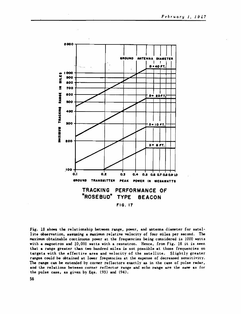
• III .... i • -III • = • • • iii 0 c • ... • ::It • • I
February 1, 1947
1000
I I I I I II IROUNO ANTINNA DIAMITER
I I " D -40 'T.
1000 100
100
700
100
100
400
100
100
/' -"'"
."...
/" ./
fI"
./ D- 10'T I---...,ttl'"
~ V ~ V
V 0- 10 'T. - .....
/ V
".
/' O •• 'T.
V /" ./
.100 0.1
/ 0.1 0.5 0.4 0.5 0.1 0.7 D.I 0.. LD
IROUND TRANSMITTER .. lAIC I'OWIR IN MIIAWATTS
TRACKING -ROSEBUD-
PERFORMANCE OF TYPE BEACON
FIG. 11
Fig. 18 shows the relationship between range, power, and antenna diameter for satellite Obsenation, assuming a maxilmllD relative velocity of four miles per second. The maximum obtainable continuous power at the frequencies being considered is 1000 watts with a magnetron and 10,000 watts with a resnatron. Hence, from Fig. 18 it is seen that a range greater than two hundred miles is not possible at those frequencies on targets with the effective area and velocity of the satellite. Slightly greater ranges could be obtained at lower frequencies at the expense of decreased sensitivity. The range can be extended by corner reflectors exactly as in the case of pulse radar. and the relations between corner reflector range and echo range are the same as for the pulse case, as given by Eqs. (93) and (94).
58

February 1, 19J,.7
200
100 en 90 ~ 80 i 70 ~ 60
w SO to ~40 a::
230 :!:)
! )(
~20
.-
---........ ~
---~ ~
~ ~
I
G~ ~
-I-" ~
--~ '""'"'
~ ....-~
~~ ...... ~'""
~ V ~ I I
I\~ ",,,,1\ 0 I ~
-H""I
iO·.¢....-..-J..-
I ._____1 i.-~
f,..oo I l.- ~I""
V i--~ I O~ ~ ~I-~ i--'~ i.- .-~ ~
~r--!
10-:..,..f,..oo, ....
I i I I i
10 100 1000
TRANSMITTER POWER IN WATTS 10000
MAXIMUM RANGE OF A DOPPLER RADAR ().·30 OR 10CM) ON A 10 SQUARE -FOOT TARGET WITH A MAXIMUM RELATIVE VELOCITY OF FOUR MILES PER SECOND
FIG. Ie
The available Doppler radar set, the AN/TPS-7. operates at 700 megacycles and has a range of 60-90 miles on a medium bomber. A proje~ted equipment will have a range greater than 200 miles, but will have a relative velocity limitation of less than one mile per second24
•
Doppler beacons can be used at lower frequencies where radio frequency amplifiers are available. Assuming the range is limited by the beacon transmitter power, range is given by
dD• • 4 x 10' u.J~ PI- Nt mil ... lIIax
(104)
Table 4 shows the power required for satellite observation. The usual practice is to employ a frequency doubler in the Doppler beacon and heterodyne the returned signal at the ground with a signal having twice the transmitted frequency.
59

February 1, 194.7
Table 4
POWER OUTPUT PD REQUIRED OF A DOPPLER BEACON FOR A 1500 MILE RANGE
ON A SATELLITE WITH A RELATIVE VELOCITY OF FOUR MILES PER SECOND
(6-FOOT GROUND ANTENNA)
>.. (ca) PD(watts)
10 256 30 24
100 3.2 300 0.8
Doppler radar is actually a form of radio interferometry and, as a consequence, is capable of yielding more than velocity information alone. Every beat note cycle represents satellite motion of half a wavelength relative to the radar station. Extreme accuracy is potentially available from this method by the use of short wavelengths.- However, as the wavelength is reduced. the number of beats that must be counted per unit radial motion increases proportionately. The large radial displacements characterizing satellite observation will introduce additional technical problema. Since Doppler radar yields change in distance relative to the radar station, tracking by Doppler radar requires both triangulation and knowledge of the target position at some initial time.
Frequenc1 Modulated Radar
A frequency modulated radar radiates a signal the frequency of which varies periodically oyer a specified lIand. The reflected signal differs in frequency from the transmitted signal because of both the finite velocity of radio wave propagation and the Doppler effect. As a consequence, it is possible to obtain radial velocity as well as distance, making the system very attractive for the satellite case. Operation at high frequencies is limited by the small frequency-shift possible with magnetrons; a 10 centimeter tube with a frequency-shift of,lOO megacycles is in the experimental stage, but will take some time to develop. An FM radar set operating at 600 megacycles is under development by the Army and has tracked a medium bomber to 165 milesu .
The great ranges and velocities involved in satellite tracking make the design problems of an FM radar system especially difficult, although certain simplification is possible if the system is allowed to act as a vernier, with approximate positions obtained by cruder means. A beacon for such a system would present many design problems, since it wauld be required to retransmit a signal synchronized in both frequency and sweep rate with the received signal. Even though FM radar has several advantages, other systems requiring less development will be considered more favorably.
• Poaitiona obtained inatantaneoualy by Doppler radar at White Sanda V-2 firinga are in error by (iYe to ten per cent of ran,e, but positions obtained by subsequent analyai. of recorded Doppler data are clalmed to be in error by less than aix feet.
60

February 1, 1947
Phase-Shift or Tone Modulated Radar
Tone modulated radar measures range by observing the phase difference between the n.odulation of the transmitted and echo signal. A portion of the transmitted signal is put through a calibrated phase-shifting network and its phase is matched with that of the echo signal. Range d is found from the relation
d a E!=t 41Tf ' •
(lOS)
where ~ is the observed phase-shift in radians of the echo signal, and f. is the modulation frequency. For long ranges the modulating frequency becomes very law, unless range ambiguity is permissible, and the measurement of the phase-shift becomes more difficult. The error of ± 0.03 miles in range measurements obtained by the Germans with their Benito phase-shift navi8Btion system is not as good as is obtainable with similar pulse modulation systems, but considerable attention is being given to phase-shift ranging and the accuracy may be considerably improved25
• It is ant1c1-pated that phase-camparison systems will eventually attain a precision of one degree of phase28.
The following are the more important points which arise from the preceeding discussion of radar modulation systems.
1. A pulse radar system, incorporating a beacon in the satellite, could be adapted to satellite tracking with the least modification of present equipment.
2. Doppler radar could be modified to measure the velocity of the satellite, but no suitable Doppler range measuring equipment is available at present. Since Doppler radar measures change in position it could be used for trajectory measurements using the launching site as a reference, but would be difficult to adapt to orbit range observations. If differentiation of the position coordinates given by a pulse radar system should prove not to give a velocity vector of adequate accuracy, the Doppler system would become of increasing importance, but at present pulse radar seems more readily adaptable to satellite observation.
3. FM and phase-shift radar systems have potentialities but require extensive development. Since FM radar gives both range and velocity information, further investigation of such a system for tracking the satellite seems worthwhile.
4. Although there are many factors to be considered in the selection of the operating frequency, the development of equipment for satellite tracking can probably be done with the least effort and expense with S-Band (3000 megacycle) equipment. The basis of the satellite observation system might be the SCR-S84 and AN/CPS-l ground radars and the AN/APN-19 beacon. Such readily adaptable equipment is not available in the 700-1000 megacycle frequency range.
IV-B-2. Position Finding by Radar Methods
IV-B-2-a. Tracking .ith a Single Radar Station
A single radar tracking station measuring range, azimuth, and elevation of a target permits determination of the position of a target at an altitude of 350 miles
61

February 1, 191,.7
to the extreme slant range of 1700 miles at a zero elevation angle. While inaccuracies in position finding caused by range measurement errors are essentially independent of the magnitude of the range, inaccuracies caused by errors in angle measurements are directly proportional to the range. This property of systems depending heavily upon angle measurements for position finding discourages their use at long ranges. For example, at the extreme satellite observation range of 1700 miles, an error in an angle measurement of one mil will result in an error in position of 1.7 miles. The best radar tracking sets have static errors slightly less than one mil, but dynamic errors and the effects of refraction on elevations angles can increase the overall error to several mils. Tracking by a single radar station does not appear satisfactory for the critical trajectory observationa, but can give satisfactory results for orbital observations if used at elevation angles greater than about 45 0
• It has already been shown that elevation angle aasurements under 50 ahoye the horizon wil~ • require large refraction corrections, and should not be used under any circUIIIStances." This restriction is not too serious because ground effects would seriously affect transmission at such low elevation angles and are sufficient to discourage low elevation observations.
IV-B-2-b. Trac~ing .ith One Radar Station and a Satellite-borne Altiaeter
The use of a satellite altimeter in conjunction with a single radar station would be the simplest athad of tracking by triangulation. Since the trajectory and orbit will be essentially two dimensional, changes in azimuth will be small, slowly varying, and unimportant, and azimuth can be obtained with sufficient precision by a radar station. The projected range can be computed from the slant range and azimuth given by the radar and the altitude given by the altimeter information telemetered back to the ground. If a light weight, low power-drain altimeter can be developed, this method will have ptomise, but a survey of the several existing types of electronic altimeters indicates that an altitude of 350 miles would require equipment that would be too heavy and would draw too naach power to be considered at present for use in a satellite. Present electronic altimeters weigh approximately 40 pounds, draw over 75 watts, and have an error as small as 25 feet, but are limited to altitudes less than eight miles. The properties of the upper atmosphere are too little known to permit use of altimeters depending upon temperature and pressure for calibration.
IV-B-2-c. Trac~ing .ith T.o Radar Stations
The range of the satellite from two groWid stations and the azinruth from one can be used to determine its POS1t1on. Assuming a plane earth and using the notation of Fig. 19, it can be shown that
e2 + ~ - rP. " . 2 (106) 2e
d . " sec /3 (107)
z .. " tan J3 (108)
y .~d~ _ d2• (109)
Letting 8 1 be the master station, the range da can be relayed from 8 a to 8 1 by radio. A more elegant system might use station 8 2 as a radar beacon and have a satellite
62
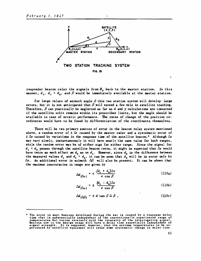
February 1, 191,.7
'I
~~:::::::~4x x 8 rt 'I,o.0)
SECONDARY STATION
I
TWO STATION TRACKING SYSTEM
FIG. I. responder beacon relay the signals fromBa back to the master station. In this manner, d 1 • d 1 + da• and ~ would be immediately available at the master station.
For large values of azimuth angle p this two station system will develop large errots, but it is not anticipated that ~ will exceed a few mils in satellite tracking. Therefore. ~ can practically be neglected as far as d and 1 calculations are concerned if the satellite orbit remains within its prescribed limits, but the angle should be available in case of erratic performance. The rates of change of the position coordinates would have to be found by differentiation of the coordinates themselves.
There will be two primary sources of error in the beacon relay system mentioned above, a random error of ± ~ caused by the master radar and a systematic error of ± ~ caused by variations in the response time of the satellite beacon.- Although ~ may vary slowly, instantaneously it will have nearly the same value for both ranges, while the random error may be of either sign for either range. Since the signal for d 1 + da passes through the satellite beacon twice. it might be expected that ~ would have twice as IlUch effect on da as on d1 • However, since da is the difference between the measured Talues d1 and d1 + da• it can be seen that da will be in error only by ~. An additional error in azimuth t¥3 will also be present. It can be shown that the maximum inaccuracies in range are given by
l::JJJ (6r) .. ± . (d1 + da}6r
( BOa) e cos ~
l::JJJ(6. ) .. ± (d! - da)~ (BOb)
e cos ~
t:J.(t¥3) .. ± d tan f3 6 f3 (noc)
• The error in most beacons developed during the war is caused by a reaponse delay time that is substantially independent of the conventionally experienced range of temperaturea but varies inversely with the intensity of the interro,ating aignal. Beacona now in the design atage will hav. a delay ti~e esaentially Independent of signal strength. It ia supposed, however, that the extreme temperatures to be experienced by satellite equipment will cause some systematic change in delay time.
63

February 1, 1947
and the maximum inaccuracies in altitude by
6.y (6,.) .. ± [d, + d (kd, - d,~ D.r e cos p y
(lIla)
6.y (6.,) .. ± [d, • d (d, - d,)] D.s e cos p y
UUb)
(UIC)
where 6d(6.r) = inaccuracy in d caused by 6r, etc.
k • ~l when % > e k ,. +1 when % < e.
While the above values are for a flat earth. they are good approximations for the true earth values.
IV-B-2-d. Tracking with Three Radar Stations
With the addition of a third ground station it becomes unnecessary to find any angles. From Fig. 20,
1 [ (d' • d')] % .. b2 + d~ - 3 2 2
2e (112)
% '" Ii! ~ d!
4g (113)
d '" -./%2 + %2 (U4)
Y .. -.Jd~ _ d2 • (115)
This system gives more accurate values of '. but yields more accurate values of d and y only if P is large. For small ~alues of~. the accuracies of the two and three station systems are approx~tely the same. For satellite tracking the greater simplicity of the two station system ia to be preferred.
64
'I SATELUTE (x.J .Z)
SECONDARY STATION. I
•J.~~~~a:~::::~~~~~~ .. '~') -- X 0,0,0) - ... - __ _
MASTER It. ~--__ STATION , I,Ce,o.g)
SECONDARY STATION .2
THREE STATION TRACKING SYSTEM 'IG.20

February 1, 194.7
IV-B-3. Poaitioa Finding by Ground Analysis of Satellite Signals
IV-B-3-a. Hyperbolic Systeas
If the difference in time of arrival of a pulse from the satellite or the difference in the phase of the satellite signal at two ground stations is determined, the locus of the position of the satellite is established on a hyperLoloid of revolution. The Loran. Gee, and Decca navigation systems211 operate m this principle, but in reversed form, since they compare signals originating from ground stations. To obtain a fix in three dimensions, three sets of two ground stations wopld be necessary, which actually would require only four stations. Since the flight path of the satellite extends above the ionosphere, a frequency for operation would have to be selected considerably above present Loran and Decca values. This would result in an increased accuracy for the inverse Loran system because steeper pulse fronts could be used. and in an increase in the accuracy of the inverse Decca system at the expense of an increase in the armiguity of position. The ambiguity in Decca position finding could be remedied by use of a low frequency mOdulating signal for the determination of the approximate position; a high frequency modulation or the radio frequency itself could be used as a vernier for accurate position finding. Present accuracy of pulse Loran is approximately one wavelength and about one per cent of a wavelength for Decca and cycle-matching Loran26
•
Making the simplifying assumptions of a flat earth, a two diRensional flight path, and equally spaced ground stations, and using the notation of Fig. 21, the location of the satellite can be determined from the following relations
" ,.
y .. (Fa _ 8~)(~ - 8:)(4Fa - [8
1 - 8J.a)
2F (8 2 + 81 )
~ (I.Y)
4, d. d.
)lox (-F,o) (0.0) (+F,o)
t GROUNO .TATIONS t a.. d.-d, at- dl"'d.
HYPERBOLIC TRACKING SYSTEM
FIG.21
(116)
(117)
65

February 1, 1947
IV-B-3-b. R.Zativ. V.locit,S,.te .. If the satellite transmitter and ground reference signals could all be kept at
precisely the same carrier or modulation frequency, a measure of the beat frequency at ground stations would give the relative velocities and changes in range of the satellite. The work of Pound on stable microwave oscillators2T demonstrates the potential feasihility of such a system. Observation of relative velocities {and no angles} at four ground stations would suffice to determine both the position and velocity of the satellite in two dimensions. The measurement of relative velocity from two additional ground stations would give the values in three dimensions. The measurement of six differences in frequency, or velocity, at seven ground stations would also give velocity and position of a body in three dimensions. The measurement of differences in velocity depends as heavily on frequency synchronization of ground and satellite signals as does the measurement of absolute velocity and has no advantage over the simpler system using absolute relative velocities.
The chief advantage of the hyperbolic and relative velocity systems is that no satellite receiver is necessary for position finding, but this advantage loses its importance when it is recalled that a satellite receiver is needed in any case for controlling the final jet burning time. The greatest disadvantage of the methods is the complex communication system needed between ground stations.
IV-B-3-c. Radio Rela1 S,.t ... Navigation systems, such as Decca, Popi, Gee, Loran, etc., in which the obser
vation of signals and the calculation of position is done in an aircraft, could be adapted to satellite tracking by having the satellite relay the signals to a ground station for computing and tracking.
As an example of a relay system, assume that pulses of differeht lengths are transmitted from four ground stations simultaneously and relayed by the satellite to a control station where three sets of differences of time of arrival would be used to compute the position of the satellite. A feature of such a system is that slow variations in the response time of the satellite beacon would not affect the accuracy since t~ differences are used. An advantage of this system over the ground analysis systems mentioned previously is the simplification of the ground intercommunication system to a synchronizing pulse. However, to obtain the accuracies demanded the synchronizing pulse must have such a short rise time that a carrier frequency of at least SO megacycles must be employed. Since the ground stations must be separated by hundreds of miles, the communication problem is seen to be complex. Dependable communication at frequencies above SO megacycles practically demands a system of relay stations located with the limitations in mind imposed by the nature of the terrain, earth's curvature, etc.
IV-B-3-d. Radio Direction Finder. The measurement of angles by raciio direction finders is a relatively inaccurate
process cOll'plred with range measurements hy radar. For this reason a position finding system based on angle measurements is not further considered.
66

February 1, 1947
V. TECHNIQUES FOR COMMUNICATIONS
Communications will playa vital role in the launching and observation of a satellite and fortunately many types of equipment have been developed that can ac· complish the required tasks. The two basic types of communication required, command control and telemeterins, are now briefly examined.
Command control is a means for exercising control from the ground over certain operations within the satellite. Such communication systems have been developed for the remote control of drone aircraft and guided missiles. Either 'on-off' or pro· portional control is usually achieved by changing the pulse repetition frequency of a pulse system or changing the modulating frequency of a continuous carrier type system. Since lon-off' control, by far the aimpler of the two systems, is the type needed for the satellite control, it is not anticipated that any serious problems will arise in applying present techniques to the satellite problem.
Telemetering is a means of transmitting instrument information, available in the satellite, to ground stations. While telemetering has undergone considerable development in the past few years·', the proper solution for the satellite problem is not an obvious one and will require an analysis of the various types of telemetering as applied to the satellite.
The most important consideration in the selection of a satellite telemetering system is the necessity of keeping power drain to a minimwr.. The number and frequency response of the telemetering channels should be kept to a minimum, since an increase in either causes at least a proportional increase in the power requirements. If the telemetering can be so designed that information will be transmitted only when desired, and if the same transmitter can be used for both tracking and telemetering, a considerable saving in the power requirements is possible. Since telemetering must playa secondary role to position finding, it would be desirable to find a satisfactory telemetering system that could be incorporated with the satellite equipment of whatever tracking system is deemed preferable.
The problem confronting a designer developing a telemetering system is the means of signalling on one radio carrier the information from several measuring instruments. One possible solution is the use of subcarriers, the variation~ of which about reference frequencies or amplitUdes indicate the magnitudes of the information. Either frequency or amplitude modulation may be used at the lower frequencies where magnetrons <which cannot be amplitude or frequency modulated easily) are not necessary, keeping in mind that flight above the ionosphere demands carder frequencies in excess of about 60 megacycles for dependable communications. Subcarrier telemetering is limited to a few channels because of troubles originating from intermodulation between channels.
Television methods could be applied to telemetering by televising to the ground a picture of instrument indicators aboard the satellite. However, the channel width required, complexity of equipment, and other engineering factors discourage the use of such a telemetering method.
A phase-shift system of telemetering has been developed that permits use of existing types of flight instruments by converting the angular position of an instru-
67

February 1, 194,7
IDeDt pointer into a correaporsdins uplar phue·shift of an audio frequency sub· carrier. The .ystem has several 8dvantages, notably a narrow bandwidth, but pickups, conversion circuits, and indicators are not available for several important types of measuremen t.
Another solution to the problem is time division telemetering, in which channel infornation is transmitted in sequence over discrete periods of time. The cOlml1tation from one channel to another is accomplished by either motor-driven commutators or electronic switching tubes. Unlike most other telemetering systelll8, the power output requirement of this system is essentially independent of the number of information channels. On the other hand, increasing the number of channels will reduce either the frequency or duration of individual channel sampling.
Pulse position modulation is a modification of time division telemetering. In this .ystem. one cycle of operation consists of a synchronizing or reference pulse followed by one pulse for each of the measurements being telemetered. There are several pulse modulation methods, but usually the position of these information pulses relative to a fixed separation from either the synchronizing or preceding pulse indicates the magnitude of the information. The sampling frequency must be about three times the naximum modulating frequency. Thus, the duty cycle is the product of the maximum modulating frequency and the number of telemetering channels, and increasing either will denand a proportionate increase in the average power output. The range considerations of a pulse position modulation system is essentially the same as discussed for beacon operation of pulse radar (Section IV-B-2-b). Pulse modulation systems are especially useful for magnetron and high frequency operation, and have been e""loyed in the NU... telemetering equipment for Army V -2 test launchings2" and for multi-channel voice communication in the familiar AN/lRC-6. Pulse modulation cannot be employed successfully at lower frequencies, since the transmission of sharp pulses requires bandwidths of the order of one megacycle.
Section IV-B-1-b has indicated that a pulse radar system with a satellite-borne responder beacon has the most promise for satellite tracking. It is apparent that the "pulse position telemetering system could be incorporated into such a tracking .ystem. In addition to triggering a tracking response pulse, the radar interrogating pulse could also initiate one train of pulses using the tracking response as a reference pulse. A valuable feature of such a system is that the telemetering data will not be tr~nsmitted except when the beacon is interrogated. The r8dar pulse repetition frequency arust be at least three times the maximum modulating frequency for a satisfactory frequency response.
VI. RECOMMENDED SYSTEM
It would be unwise to attempt to select a specific and final tracking and telemetering system for the satellite at this time, since the arts are evolving so rapidly. This section will provide details of the system which for the present is recommended as haying better possibilities than the other systems outlined.
68

February I, 1947
In the interests of power, weight, and space economy in the satellite, a combined tracking and telemetering system has heen provisionally adopted, and an operating wavelength in the region of 10 centimeters selected. In the summary at the end of Section III it was pointed out that the optimum band of useful wavelengths for such a combined system was from approximately 10 to 40 centimeters. The presence of cosmic noise and occasional bursts of solar noise in the wavelength region from about 1.5 meters and upward provides additional grounds, if any are required, for the use of centimeter waves. The most suitable equipment available in the region from 10 to about 40 centimeters is at the 10 centimeter end of the band, and it is for this reason that 10 centimeters has been selected as the operating wavelength, despite the son~what more attractive characteristics of the longer wavelengths.
The operating system for the launching operation is basically the system described in IV-B-2-c. It is a two station triangulation system utilizing a beacon in the satellite as a relay between the ground stations. This system does not demand drastic modification of existing techniques or equipment, and the ground communication system is relatively straightforward. Two master radar stations and two beacons are placed along the equator under the planned launching trajectory. Orbital observations, other than over the launching area, are made by ten suitably placed tracking radars. Since the life of the satellite-borne beacon is limited, a corner reflector should be extended when the satellite reaches its orbit to increase the range of the orbital-tracking radars during later periods.
VI-A. DISPOSITION OF EQUIPMENT
As illustrated in Fig. 22, radar stations will be located along the equator approximately 200 and 2700 miles from the launching site. Associated ground radar beacons will be 550 and 1400 miles from the site. These stations should be as nearly directly beneath the planned tracking trajectory as practicable, and if stations must be located far from the equator the two station system should be replaced by the three station system of Section IV-B-2-d. Locations fo~ the ground stations have been chosen such that a minimum number of ground installations is required, but considerable care has heen taken to provide good accuracy at the critical periods of the trajectory. The first critical period occurs from about 300 to 500 miles from the launching site, or just prior to the third stage coasting period, while the second critical period occurs during the final jet burning, between 2400 and 2500 miles. The stations are so placed that they are not required to track directly overhead or at elevations less than 5° during a critical portion of the launching trajectory.
Since successful launching does not depend upon especially accurate observations during the first 250 to 300 miles of flight, an entirely separate radar or optical tracking system may he used to make a record of this part of the launching trajectory. It will be noted, however, that only the first 20 miles of flight will take place at an elevatIon angle of less than 5° as seen from the first master radar station.
Orbital tracking other than during the launching operation will be done by individual radar sets with approximately equal separations along the equator. The total number of stations N needed for observation of a complete orbit of minimum
69

February 1, 1947
altitude Y.' with radar elevation angles restricted to values greater than e, where e is expressed in degrees, is given by
N = cos -1 l(8~os a ~ • e' 1
y. +
a
(118)
where a is the radius of the earth in the same units as y.' On the other hand, y. is siven by
y = a •
TRAJECTORY SYMBOLS
• JET BURNING PERIOD • COASTING PERIOD
--- ..•.• • ORBIT
LOCATION OF GROUND STATIONS ALONG TRAJECTORY
FIG. 22
(119)
FIg. 23 gives the above equations in graphical form and also shows the separation needed between ground stations. Fractional values of N must obviously be raised to the next higher integer. Since two of the necessary stations will be the master ground stations of the launching operation, the necessary additional stations for complete orLital observation will be N - 2.
70

February 1, 1947
0 0 0
10 9 8 1 0 8 0
5 0
4 0
3 0
, , \ '\
' '\. \ 1\ , , \ '" \ \ " " \\ ~
200
300
400
500 600
"' ~ MINIMUM ELEVATION ANGLE
100 800 900 (I)
(I) z 22 ~ ~
-.., \\ \ \
~ " '" ~
"-. """" ~
~
t ~ r--.-. 45---.. r--~
r--- , -~
1000 w ..J
i ~ -i
~I 0 ~ .......
~ ~ "'
~ I---i"""ooo....
2000 z 2 !c a: a:
<I)
.... o a: w lD
! z
9 ~ ~ --... 15-8 .......... ..... """--1 8
........ '""-- ---- 5--!5 ,-
4
3000 f w (I)
4000
5000 ~ 8000 !c 1000
t;
3 I- 8000
9000 10000
2
I o 100 200 300 400 500 &00 100 800 900 1000 1100 ltoo 1300 1400
MINIMUM ALTITUDE IN MILES
NUMBER OF GROUND STATIONS AND STATION SEPARATIONS REQUIRED FOR OBSERVATION OF A COMPLETE ORBIT
FIG. 23
If the velocity, path angle, ana height of the satellite at commencement of free flight all lie within the tolerances statea. in II-A, but- deviate from tne Ideal values in such a way that the most elliptical orbit is obtained, that orbit would pass about 250 miles above the earth's surface at its closest approach. To track the satellite on such an elliptical orbit at all times it is necessary to space the orbital tracking stations as if the satellite were on a circular orbit at a hel~ht of 250 miles. Tlle numher of stations installed. for orbital tracking purposes must be a compromise be· tween the number required for lI.aximum accuracy and the minill,ulT! numLer required for continuous observation. If elevation angles w.::re kept above 45° as recorr.mendea in
71

February 1, 1947
Section IY-B-2-4. Fig. 23 shows that fifty-two ground stations separated by 500 miles would be needed. If zero elevation angles were permitted, only 9 stations would be required, but Section III has demonstrated the difficulties encountered when using angles much below S°. Fig. 23 shows that if elevation angles of S° are tolerated, a total of 12 stations separated by approximately 2000 miles is necessary. Two launching radars plus ten additional orbital tracking radars seem to be a reasonable compromise.
VI-B. MODE OF OPERATION The tracking operation by means of the satellite-borne responder beacon and the
ground radar and beacon stations is illustrated in Fig. 24. A one-microsecond interrogating pulse is transmitted by the master grouna station. This triggers the satellite beacon which responds with a two microsecond pulse to both the master radar and ground beacan stations. The ground beacon responds with a two microsecond pulse which in turn triggers a four microsecond pulse in the satellite beacon. Fig. 25 shows the tracking pulses as viewed at the master radar station. If the satellite beacon has a response delay tiDe of t. microseconds and the ground beacon a delay time of t, microseconds, the slant ranges are given by
(120)
d = 0.0931 (t 2 - t - t - t ) miles II 1 • i •
(121)
using the notation of Figs. 19 and 25. This information, plus the observed azimuth angle at the master station, will be fed to an electronic computer at the master station for calculation of the ground range and altitude. The velocity vector will be found by differentiation of the position coordinates.
~~ plan must be followed in switching from one observation station to another. As shown in Fig. 22, the first switch in stations occurs 900 miles from the launching site when the second ground beacon replaces the first. Se~eral schemes could be used for timing the shift, but it seems preferable to have the master radar station in control. When the computer indicates a ground range of 900 miles, orders for the replacement of the first beacon by the second can be sent by radio from the master station to the two beacons. A second switch in stations occurs at 1400 miles when the secona master radar replaces the first. The second radar can track the beacon response without transmitting any signals of its own until the first rauar inaicates the transfer of control by ceasing transmission. The resultant break in satellite beacon signals will be the signal for the second master station to take control.
Telemeterin~ is accomplished by using a pulse position modulation nethea in which the synchronizing, or reference, pulse is the response pulse of the beacon to the master radar station, and each such pulse is followed by a chain of 15 telerr~tering pulses. The final jet is turned on by changing the pulse repetition frequency of the master grounD station. After the critical horizontal velocity has been reaclteCl Clurlng the final thrust, another chan8e in the master raoar pulse repetition frequency turns on a satellite-borne Doppler altineter. The final jet is turned off' without further reference to the ground station when the altimeter indicates a sufficiently small v~rtical velocity component.
72

February 1, 191,.7
SATELLITE BEACON
DIAGRAM OF BEACON ACTIONS
INTERROGATING PULSE Ip.IIC.
FIG. 24
FIRST RESPONSE
21£ SIC.
SECOND RESPONSE
4p.11C.
TRACKING PULSES AS VIEWED AT MASTER GROUND STATION
FIG. 25
GROUND BEACON

February 1,1947
VI-C. TRACKING
VI -C-l. Ground Radars
Grouna radar stations will not have to differ greatly from conventional tracking systems. To keep satellite requirements to a minimum, the ground radar antenna area and radio frequency peak power should be made as large as possible and the receiver noise level kept as low as possible. The specifications given in Table 5 represent values that seem reasonabl~ at the present time.
Table 5
SPECIFICATIONS OF GROUND RADAR EQUIPMENT
Tranamitter
Receiyer
Antenna
RF Frequency·
RF Peak Power
mF
Pulse Width
RF Frequency·
If Band Pass
Noise, db ahove KTB
Pulse-width discr~ination
3000 Mc/s
1 Mw or greater
40 p~s (variable)
I }.Ls
2990 Me/s
I Me/s
15 or less
Against pulses shorter than 1.5 }.Ls
Spinning dipole 10 punch~d paraboloid
Diameter 10 ft
2.30
5400
He amwid th
Gain over isotropic radiator
Target Followins
Automatic and aIded
The radar pulse repetition rate has been selected as 40 pulses per second to avoid range ambiguity and allow till'.e for a train of telemetering pulses to follow the satellite beacon response. With such a low pulse repetition frequency the satellite position will change by as much as 0.1 miles between pulses, and position data must be smoothed before being differentiated for velocity information. Monopulsing, or sin.ultaneous lobing, may be a necessary refinenent. If automatic range tracking at this low pulse repetition frequency will not give the precision desired, range ambiguity will have to be tolerated and a higher pulse repetition frequency used.
• Theae exact frequencies are ,iyen to illuatrate the relation between systems and do not n.c •••• rily repre.ent .x.ct frequenci •• to be u.ed.
74

February 1, 1947
The carrier frequency of the ground transmitters will be slightly less than that of the satellite transmitter. The ground radar receivers will be tuned to the satellite transmitter frequency and thus will not be susceptible to dirp.ct echoes. Because of the narrow receiver bandwidths employed and the possibility of drift in the airborne transmitter, a good automatic frequency control system will be needed in the ground receivers. A pulse-width discriminator, discriminating against pulses shorter than 1.5 microseconds, is included in the radar receivers to eliminate telemetering pulses.
VI-C-2. Ground Beacons . The ground beacons will be designed around conventional techniques and circuits
except for two major considerations. The beacon antennas will he as large as possible, but must be restricted somewhat in order that these units may be shipborne. Due to the narrow beamwidth, complete stabilization must be employed. Secondly, the beacon antennas should be capable of automatically tracking the satellite. This will reduce the satellite power requirements and at the same time allow the beacons to assume prime observation responsibility should the satellite drop out of sight of the master stations. Table 6 gives an outline of the specifications for the ground beacon equipment.
Table 6
SPECIFICATIONS OF GROUND BEACON EQUIPMENT Transmitter
Receiver
Antenna
RF Frequency
RF Peak Powe r
PRF
Pulse Width
RF Frequency
IF Band Pass
Noise, db above KTB
Pulse-width discrimination
Conical scan in punched paraboloid
Diameter
Beamwidth
Gain over isotropic radiator
Target Following
Automatic and aided
3000 Mc/s
1 Mw or greater
40 pps (delayed response)
2 j.Ls
2990 Me/s 1 Mc/s
15 or less
Against pulses shorter than 1.5 j.LS
and greater than 3 ~.
10 ft
2.3 0
5400
The pulse-width discriminators in the ground beacons pass pulses between 1.5 and 3 microseconds 1n duration. Such discrimination prevents trig@ering by telemetering pulses or satellite beacon responses to ground beacon pulses. Thus, the ground beacons will respond only to those satellite pulses triggered by master radar interrogation.
75

February 1,1947
A standby modulator is required should independent observation of the satellite Ly a beacon become necessary. At other times the beacons will perform in the normal beacon manner and will incorporate a carefully controlled delay time. Receiver and frequency considerations are the same as in the case of the ground radar stations.
VI-C-3. Satellite-borue BeacOD
TIle satellite beacon will consist basically of a modified and iq>roved 'Rosebud' type responder beacon. The receiver sensitivity and peak pulse power are greater than usual airborne beacon values to permit long range operation. Additional components will be added for control and telemetering purposes, as shown in block form in Fig. 26. A pulse-width discriminator will pass the two microsecond ground beacon pulse directly to a four microsecond pulse forming modulator. The one microsecond pulse from the master radar stations will trigger a two microsecond pulse plus a chain of one microsecond telemetering pulses.
It has been estin.ted that the satellite beacon and telemetering equipment will require about 250 watts, weigh 300 pounds, and occupy six cubic feet. Since heat cannot be dissipated Ly convection at the low air densities to be experienced, heat radiating fins and a greater than usual volume for a given amount of equipment may be necessary.
The type of antennas to be used for the teacon will not be discussed, since their selection is a con,plex problem which will probably require considerable experimentation. Experience with guided missiles indicates that some form of stub-dipole or slotted-cavity antenna may be satisfactory. Current tracking of V-2's has demonstrated. under conditions of imperfect rocket attitude stabilization, the need for a beacon antenna giving circularly polarized radiation.
Table 7
SPECIFICATIONS OF SATELLITE-BORNE BEACON EQUIPMENT
Transmitter
Receiver
RF Frequency
ru:- Peak Power
Pulse Width
Average RF Power
Frequency Stability
RF Frequency
IF Bandpass
Sensitivity
Stages
2990 Mc/s
2000 watts
4 ~s for response to 2 ~ pulses 2 ~s for re sponse to I ~ pulse 1 ~s for telemetering pulses
1. 74 watts
2 ~k/s or better
3000 Me/s
4 Me/s
5 X 10- 11 watts or less
7IF
Power Required (inr.luding telemetering equipment)
250 watts
76

~ ~ RECEIVER 2"lIc 4"," POWER
PULSE PULSE OSCILLATOR ....
I ~ I + l I - PULSE LENGTH ~ PULSE POWER - ... DISCRIMINATOR I-
FORMING MOOlLATOR -CIRCUIT
PRF PRF 1,,'10 BLANKING FILTER *1 fiLTER #2 PULSE PULSE 2~lc ... TELEMETERING
l' P LSES
~ \ TELEMETERING CIRCUIT
~
, JET ALTIMETER MAGNETIC TO~ND
• ON" CONTROL POWER SUPPLY ROll-REfERENCE INSTRUMENTS CONTROL
¢ \ -- TO END INSTRUMENTS
~ f ALTIMETER - ALTIMETER
~ SUB - AUDIO TO JET "oFF" CONTROL
TRANSMITTER RECEIVER fILTER
TO SERVO
BLOCK DIAGRAM OF SATELLITE BEACON AND TELEMETERING EQUIPMENT
fiG. 26

February 1, 1947
VI-C-'. Ccaputers It will be necessary to employ two computers during the launching operation.
The first will determine the satellite position and velocity from the data obtained frClll the observation system. Fig. 27 illustrates in block form a possible computer for the two station triangulation system. The illustrated computer applies to a flat earth and must be modified to take the earth's curvature into account. A second computer will calculate the length of coasting time necesaary to place a rocket having the positions and velocities determined by the first computer on the best possible orbit.
VI-C-S. Trackil'll' Inaccuracies
Two sources of inaccuracies in position will predominate in the receR,mended trackint system - a random ranging uncertainty caused by errors at the master ground station and a systematic error caused hy variations in the response time of the satellite-borne beacon. Errors (and the resulting inaccuracies in position) caused by nriations in the responae time of the ground beacons and by non-systematic variations in the satellite beacon response time are a~sumed to be small enough to neglect. At the operating frequencies selected, range errors resulting from neglecting syste"tic group retardation of pulses passing through the ionosphere are not likely to exceed 13 feet (see Fig. 12) and are not considered.
Figs. 28 and 29 show the maximum inaccuracies in ground range and altitude along the trajectory, c_Iculated from Eqs. (110) and (Ill>. when the azimuth angle is zero or Tery s.ll. The curves were plotted assuming a random error of to.01 miles and a ayst_tic error of to.04- miles. As drawn, the two sources of inaccuracies considered haTe been combined in whatever manner i. appropriate to show the maximum possihle inaccuracy. Since both errors are pessimistic and since it is unlikely that both would have maximum values of the same sign simultaneously, the maximum inaccuracies shown are not likely to be realized. Fig. 30 illustrates the effect of an azimuthal error of t1 mil. A study of the three curves will show that large inaccuracies in position are possible during the coasting period, but the inaccuracies will be less than to.OS miles in ground range and to.10 miles in altitude during the critical portions' of the trajectory. Although the systematic error of the satellite beacon introduces moderate inaccuracies in position measurements', velocity and path-angle measurements are less seriously affected.
VI-D. TELEMETERING
VI-D-!. Satellite-borne ec:..onents
As shown in Fig. 26, the one microsecond pulse from the master radar station initiates a two microsecond response, or synchronizing pulse, plus a train of fifteen telemetering pulses, each of one microsecond duration. The position of each pulse relative to either the synchronizing or preceding pulse is used to signify the magnitude of the quantity being telemetered.
The telemetering modulating circuits should, in general, follow the design of the JIItL pulse position system now being used in V-2firings2 9. The RF section of the beacon will also serve for telemetering. Telemetering data will run for 16,000 micro.econds for each train, permitting a deviation of as much as 500 microseconds per channel. Since each channel is saapled 40 times per second, as determined by the
78

-I '0
MEASUflED PARAME FROM R
TERS AllAR
& .-- SQUARING CIRCUIT
SQUARING CIRCUIT
KNOWN PARAMETERS
,I I ~
L_G ,\ .. 1 ... 1
4.1- .. : '-ADOING '--- MULTIPLYING ~ MULTIPLYING
.. ~r ClRCUT CIRWT CIRCUIT - CIRWT '''''f-4:
SQUARING ~ CIRCUIT
.' SECANT
.m __ SUBTRACTING '-- CIRCUIT
TANGENT - MULTiPlYING - ,All,. CIRWT
BLOCK DIAGRAM OF COMPUTING MACHINE FOR FINDING SATELLITE POSITION FROM DATA OF" TWO GROUND STATIONS
FIG. 27
UNKNOWN PARAMETERS
t\ I • : .... I He /J
f--
.. : ... ' SQUARE ROOT I~d~ CIRWT
,
,I •• ~ .• ~ TIIIt/J -.-.- z

~ .07
!i a:: :;) o
.06
.0 5
~
~.O 3 z
2
.0 I
o o
/ I I
·V TY"kS OF INACCURACIES RANDOM
~ ----- SYSTEMATIC / --- TOTAL
\ V ~ \
/ , // " -
\ / -j 1/ \ , \ /"" -- 1\ / ,
i-'
1/' " ~- V \
" / V" \ / \ J ... \ ! .' V ,I ,r 1', \ ,/
~- ' 'X /,1
\ /, V ,
V ~I\ j. II' ", HIBI~ ,,/ 1\, / /1
r--...... ",
~\ " j V\
~ \ \
V-~
/1 HI B2 V " /
\ I r'\ / V HI B. ,
~ ~ \ 1/ It b<: f\ 1\' -
I \ \ I -~ , /
\
" \ III
, ~
\ , , " ", I , , 'J \ I , ,
II , ;
500 1000 1500 GROUND RANGE IN MILE S
2000 2500
RANGE INACCURACIES OF RECOMMENDED SYSTEM WITH ZERO AZIMUTH ANGLE FIG. 28

O. 14-,--
O. 12
10
~,O 8 a:: J o o 4 Z -.0 I"
&IJ a J t: !:; ..
-y 4,0
.0 2
0 o
i/r
I
/ II ~-I j
I I J /
~ I
HIB.
I..---
"-l/
- ' ....
" "
1\ \ l~ \
\ \ I \ V V \
~ I
\ ~/
1\ J J
I~ ~ J 1', 1/-:' r-. f\ 1 " ~ V r",
I'........ ~
500
\
TylS L tNAcluRJclEs ~ RANDOM ----- SYSTEMATIC
\ --- TOTAL '\ , \ ,
~\ V 1--' ...... ,
\ " ,'~
\ \ /
V V 1\, \ \ I ~- -- -...... 1\ \
, ,,' ~ "" V \ 1\
V v/
II \
/ I \ \ V ,.
II / \ / \ (\ \.
/ V ~ ~\
J
~ I HzB1 -~
HI Bt-..t ~~ , f
" ~ r--..... / ,
t'-...... r-- ........
"" ~ I--~ r-- t--..... L / 1' ...... I-""""
1000 1500 2000 2500 GROUND RANGE IN MILES
ALTITUDE INACCURACIES OF RECOMMENDED SYSTEM WITH ZERO AZIMUTH ANGLE FIG. 29
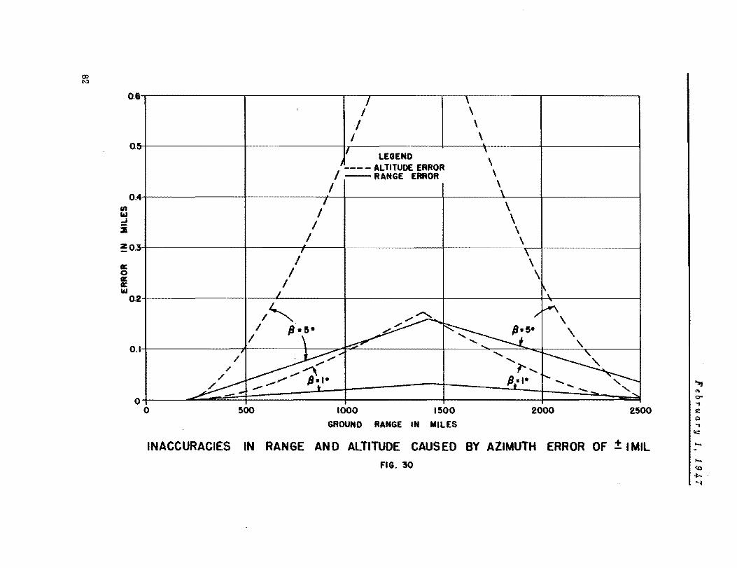
en It.I .J i
0.6
0. "'-'"
4 O.
!0.3
a: o a: a: It.I
O. 2
o .I
o
I \ I \
1 \ I \
II \ LEGEND
1 __ __ ALTITUDE ERROR \ I - RANGE ERROR \
I \ \
I \ I \ I \ I \ i
I
\ I I \
I \. I
1"'- ~ /'
,.A'\
\ 1 /l. 5- ~~- \ / \ ' ..... ,
/' ~; , -..
~ ,
,/ 1', / ,/~ / ."..,""" /lei- /l:I- '- , ~ .".., t --.. '-,
o ~oo 1000 I~OO 2000 2~
GROUND RANGE IN MILES
INACCURACIES IN RANGE AN 0 ALTITUDE CAUS EO BY AZIMUTH ERROR OF ± I MIL
FIG. 30

February 1, 1947
ground radar repetItIon frequency, the maxImum frequency response will be approximately 40/3 or 13 cycles per second.
It is apparent that the satellite beacon may be transmitting telemetering information when the ground beacon pulse reaches the receiver. The pulse width of the tracking pulse is four times wider than the telemetering pulse, however, so telemetering will not prevent relaying of the ground beacon pulse. During the transmission of the four microsecond response to the ground beacon signal, -the telemetering equipment is gated from operation and one telemetering pulse can be missed. This will not be serious, since ranges vary so rapidly that a single channel will be affected only for a second or so.
VI-D-2. Ground Equipment
It is recommended that the telemetering signals be received on the ground at a position somewhat removed from the immediate presence of the master radar stations. A directional antenna like that of the master radar stations should be used. It may always be kept directed on the satellite by means of a servo link with the nearby master radar. A pulse width discriminator, discriminating against pulses greater than three microseconds in duration, will prevent misreadings from signals relayed from the ground beacon by the satellite. The reception, decoding, and indication of telemetering intelligence can use conventional techniques and should be straightforward.
VI-E. SPECIAL EQUIPMENT
VI-E-l. Variable PRF Control
Certain functions within the satellite will be controlled from the ground by .ariation of the PRF of the second master radar station. When it is desired to restart the third stage rocket motor, a change in the PRF of the radar station is made. On detection by means of a PRF filter in the satellite (see Fig. 26) the motor is started. After the critical horizontal velocity has been reached, another change in PRF will turn on the Doppler altimeter. Remo.te cont,rol by varying the PRF of the SCR-S84 is standard practice24 and the satellite application should not introduce any new problems.
VI-E-2. Doppler Altimeter
The Doppler altimeter will be turned on by PRF control after the critical horizontal velocity has been reached (see Fig. 26). This altimeter will operate at 100 megacycles and heterodyne a portion of the transmitted signal with the echo signal from the ground. The frequency of operation is again a compromise between a lower frequency for more efficient operation and a higher frequency to permit use of a higher cut-off frequency in the amplifier without increasing the critical velocity. The receiver amplifier ideally would be a DC amplifier with a very low upper cut-off frequency. However. the great amplification required and stability difficulties demand that an AC amplifier with a narrow band-pass filter of as low a frequency as practical be used. When the beat note reaches a band-pass frequency the vertical velocity of the satellite is smaller than a predetermined value, and the final jet i. turned off by the action of the altimeter. The narrow receiver bandwidth permits use of a transmitted power of a few watts. If the upper cut-off frequency of the
83

February 1, 1947
receiver were 20 cycles per second, -the critical vertical velocity for cut-off would be given by
v :: ± 'A.6.f /2 :t 100 feet per second.
Reducing the upper cut-off frequency of the receiver would reduce the critical vertical velocity, but would increase the weight of the altimeter. The width between half-power frequencies of the receiver will be governed not only by weight restrictions, but also by the rate of change of vertical velocity to be expected. In addition to turning off the final jet, the altimeter action will turn itself off, switch end instruments from trajectory to orbital observations, switch the servo-mechanisms and controls, and switch the output of the pulse repetition rate filter number two to the magnetic roll-control device3o•
Table 8
DOPPLER ALTIMETER SPECIFICATIONS
Transmitter
RF Frequency
RF CW Power Output
Frequency Stability
Receiyer
Bandpass
Power Required
100 14::/s
3 watts
Unimportant
5-20 cps approximately
30 watts
VII. RECOMMENDATIONS FOR FURTHER STUDY AND DEVELOPMENT
Although use of available equipment was a major factor in the selection of the recommended system, some development and modification of present equipment will be necessary to bring the system into operation. It is also possible that developn~nt work now in progress throughout the country may lead to a system that is superior to the one recommended. Some specific items for further investigation and development are discussed briefly in this section.
84

February 1, 19J,.7
VII-A. DEVELOPMENT OF COMPONENTS OF RECOMMENDED SYSTEM The ~round equipment of the recolllllended system will demand no new techniques
but will require modification of existing equipment. The master ground stations can be sinlilar to the SCR-584 <as modified to permit variation of the pulse repeti tion frequency), with the maximum range sweep extended to 1800 miles, the antenna diameter increased to ten feet, and the peak power output increased to one megawatt. The ground beacons will be similar to the master radar stations, but must have provisions for switching from normal responder operation to self-pulsing.
While the satellite beacon will demand no new techniques, its development will present many problems. The sensitivity of the beacon receiver will have to be approximately 5 x 10- 11 watts and the peak power two kilowatts - values in excess of conventional characteristics. Since the receiver will have greater frequency selectivity than is usually the case for beacons, the increase in sensitivity should not be difficult. The PRY filters, pulse discriminators, pulse forming circuits, telemetering circuits, and power stages will all be modifications of existing equipment and should not cause any serious problems, other than keeping power drain and weight to a n.inimum. Other problems of a serious nature in the design of the satellite electronic equiprrent will he the protection against the variations in acceleration, temperature, and pressure. The maxin.um acceleration expected is 5g and since conventional airborne equipment is capable of withstanaing a force of IO~ for ten minutes31
, acceleration will not cause any new problems. However, the maximunl temperature expected on the orbit is about 1130 C32
• well above the 71.1° C usually met by airborne equipment31
• Moreover, the equipment will be operatin~ in a near vacuum and cooling by convection will he impossible. Either the equipment must be designed to meet this new high temperature requirement or means for cooling must be divised. The variation in temperature and the cooling difficulties combine to make frequency stability a difficult problem, but the use of a cavity resonator would probably result in adequate stability. The ~reat variation in air pressure (7.59 x lOa to 4.52 x 10⁻⁸ mm of Hg)8 demands that the equipment be protected avainst voltage breakdown. Ordinary airborne equipment has not been required to operate at pressures lower than 87.S mm of Hg31 (altitude of 50,600 feet). Perhaps evacuating, instead of the conventional pressurizinv. of equipment will .be prac~icable, since the vacuum can be established just prior to launching and the equipnent construction made adequate to hold the vacuum until the low pressure of the orbit is reached. Since voltage breakdown at very low pressures takes place between points of maximum separation rather than between minimum separations", as is the case at higher pressures, considerable care in the placement of equipment will probably be necessary.
The development of the Doppler altimeter will probably cause no serious prohlems other than the prevention of exc~ssive transmitter-receiver leakage. The transmitter could, for example, consist of a power oscillator usin~· a recently developed type of vhf triode. The receiver will probably consist of a crystal mixer section, three low-pass sub-audio stages, and a power stage. Care must be taken to prevent the transn,itter frequency from drifting so rapidly that a false beat frequency results.
Extension of a corner reflector from the satellite when on the orbit would gIve an increase in echo observation range and accuracy, and permit trackin~ after the power supply or electronic equipment in the satellite has failea. Since dra~ is likely to be negligible at orbit heights, the installation of an extenriaLle trailing or rigidly fastened corner reflector should cause no engineerin~ dif ficul ties. .5hou10
0::

February 1, 194,7
the satellite equipment fail during the launching, it would be desirable to have powerful, long-range radars available to give an indication of the flight path. Radar systems capable of the task are in the process of development and should be completed prior to the first attempts to launch a satellite.
A reduction in satellite power requirements of as much as 50% is possible subject to successful development of vacuum tube cathodes heated by radioactive means. The appendix provides further discussion of such a scheme.
Problems associated with antennas and computer construction will require considerable and detailed attention.
VII-B. STUDY OF ALTERNATIVE SYSTEMS
The following tracking aids considered earlier have qualities that would render them useful for satellite tracking if their development were carried to completeness:
Rn
1. FM and Doppler radars, because of the possibility of obtaining position as well as velocity directly.
2. Inverse Decca or Loran type systen~. because of the simplicity of the satellite-borne equipment despite the need for complex ground equipment.
3. Altimeters, even though a preliminary survey has indicated that an altimeter working at altitudes as ATeat as 350 miles would be extremely heavy and require considerable power.

February 1, 1947
APPENDIX
RADIOACTIVITY AS A SOURCE OF POWER
FOR HEATING ~ACUUM TUBE CATHODES ;. \,.
Because of the stringent limitations in continuous power available in the satellite, it is necessary to explore all neans of reducing requirements from the auxiliary power supply without curtailing the general program of communication and observation.
In most electronic apparatus, and in particular in the types required for pulse work, many of the vacuum tubes are performing specific functions requiring the drawing of plate current only for a small fraction of the time. For the remainder of the time their cathodes, which must be kept hot, are sirrply dissipating power as heat. It is safe to estimate that about half the input power to the equipment is wasted in heating cathodes, and for equipment utilizing a great many vacuum tubes, mas t of which perform relatively menial tasks, this wastage may seriously restrict what Can be done with fixed power availahle.
It has heen suggested3• that radioactive isotopes may have application as cathode
materials in vacuum tubes. Certain of these known isotopes are capable of liberating sufficient heat to keep the cathodes at a temperature necessary for adequate ther~ionic emission, without any drain on an external supply. Such cathodes or filaments will have a useful lifetime of the order of the mean life of the isotope.
While other possihle isotopes should be investigated, polonium, in particular, has been suggested as suitable, since it emits very little dangerous y-radiation when it disintegrates, and is therefore relatively easily and safely handled. The usefulness of polonium can better be understood from the following calculation.
Since one curie corresponds to 3.7 x 10¹⁰ disintegrations per second, and the mean life of polonium is about 200 days, one curie of polonium corresponds to:
3.7 X 1010 x 200 x 24 x 60 x 60
= 6.4 X 10¹¹ disintegrations 1n mean life.
Dividing hy 6.0 x 10²³ (Avogadro's number) and noting that the atolllic weight of polonium is 210, this corresponds to:
6.4 X 1011 x 210 6.0 x 1013
= 2.2 x 10-· grams
$ 0.22 milligrams.
87

February 1,1947
The energy of disintegration of one polonium atom (the kinetic energy of the emitted a-particle plus the recoil of the remainder) is 5.3 x 10⁸ electron volts. Since one electron volt is equal to 1.6 x 10- 13 ergs. one curie of polonium liberates:
• 3.1 X lOG ergs per second
• 0.031 watts.
But it has previously been shown, assuming constant actIvIty for the period of the mean life, that me curie of polonium weighs 0.22 DI@ •• and it follows that the 'efficiency' of polonium* for cathode heating can be expressed as:
0.22 • 7.1 milligrams per watt. 0.031
It i. seen therefore that the mass of the polonium required to make a cathode is of the same order of mas. a. conventional cathodes. To supply 200 watts of cathode heating will therefore require less than one and a half grams of polonium. Cathode heating required by the .atellite~borne electronic equipment is probably somewhat less than this figure.
Since disintegration bombardment and recoil tend to cause spontaneous dispersal of polonium. it has been suggested that the polonium be inserted into a fine tube of some other metal and drawn to suitable filament dimensions. Whether such a filament has too great a surface to permit the development of temperature suitable to the required thermionic emission will require further investigation along with the more 'general problem of determining the surface temperature of a cathode as a function of its surface area per unit mass of polonium.
Typical of the numerous problems which will arise and require solution before polonium can be used for cathodes are the problem of what to do about the 1. 2 x 10¹³
atoms of helium liberated per second per watt**and< the problems associated with the use of vacuum tubes with a determinable decay rate for cathode emission.
Clearly the matter of using radioactive isotopes for cathode materials in vacuum tubes requires practical development. but offers considerable promise as an ultimate means of reducing the output required of a satellite-borne power plant.
• For the purpoae of co_pariaon it ia pointed out that radiUM ia only about 1/5000th aa 'efficient' aa polonium. i.e. 5000 timea aa much radiUM i. required per watt .
•• Thi. corre.ponda to an accumulation at the end of 200 day. of about 0.8 cc of helium at NTP per watt equiyalent 01 polonium.
R8

February 1, 1947
REFERENCES
Third Quarterly Report, RA-lS013, Project RAND, Dou~las Aircraft Company, Inc., De_c. I, 1946.
a Krueger, R.W.; Grimminger, G.; and Tieman, E.M.: Flight Mechanics of a Satellite Rocket, RA-lS0 21, Pr oject RAND, Douglas Ai rcraft Company, Inc., Feb. 1. 1947.
3 Bailey, O.K., and Lipp, J.E.: Study of Launching Sites for a Satellite Projectile, RA-15029, Project RAND, Douglas Aircraft Company, Inc., Feb. 1, 1947.
4 Clement. G.H.: Structural and Weight Studies of a Satellite Rocket, RA-lS026. Project RAND, Douglas Aircraft Company, Inc •• Feb. I, 1947.
to Gendler. 5.1..: Satellite Rocket Power Plant, RA.15027, Project RAND. Douglas Aircraft Company, Inc •• Feb. I, 1947.
e M~ller, G.: Photometrie der Gestirne, Wilhelm Engelmann, Leipzig, 1897.
1 Chauveeet. W.: A Manual of Spherical and Practical Astronomy •. Vol. I, Sth Edition, J.B. Lippincott Company, Philadelphia, 1891.
8 Grimminger, G.: Analysis of Temperature, pressure, and Density of the Atmosphere Extending to Extreme Altitudes, RA-1S023. Project RAND, Douglas Aircraft Company, Inc.,
8 Norton, A.P.: A Star Atlas and Ref,rence Handbook, 5th Edition, Gall and Inglis, LonQon, 1933.
10 Pawaey, J.L.; Payne-Scott, R.; and McCready L.L.: Solar Radiation at Kadio Frequencies and Its Relation to Sunspota, Report RPR 24. Diyision of Radiophysics, Council for Scientific and Industrial Research, Melbourne, 1946 •.
11 Carroll. T.J.: Private Communication, Jan., 1947.
12 Millington, G.: Funda_ntal Principlea of Ionospheric Tunaminion, Part I, Baddow Heport 990, Britiah Admiralty, Sept., 1943
13
10
Ionospheric Data, Report IRPL-FI4, Interae'rYice Radio Propagation Laboratory, National Bureau of Standarda, Waahington, October, 1945 (and subsequent iasues to date ) •
........ --Report on Japanese Research on Radio Waye Propagation, Vol. II, General Headquartera, United States Army Forces, Pacific, Tokyo, May, 1946.
Ionospheric Data, Report CRPL·F27, Central Radio propagation Laboratory, National Bureau of Standards, Washington, Nov., 1946.
18 Dimitroff. G.Z., and Baker, J.G.: Teleacopes and Accessories, The Blakiston Company, Philadelphia, 1945.
11 Russell. H.N.; Dugan, R.S.; and Stewart, J.Q.: Astronomy, 2 Vola., Ginn and Company, Boaton, 1927.
18 Blau, ~~, and Feuer, I.: Radioactiye Light Sourcea, J. Opt. Soc. Am •• 36, 10, Oct., 1946.
18 Howstoun, R.A.: Vision and Colour Viaion, Longmans, Green snd Company, London, 1932.
89

February 1, 1947
ao In@alla, A.G. (Editor); AMateur Telescope Makins Advanced, Munn and Canpany, 1937.
al Norton, K.A., and ember" A.C.: Maximum Range of a Radar Set, Proc. I. R. E •• Vol. 35, Jan., 1947.
aa Kaeff, A.V.: Minimum Detectat-Ie Radar Signal and Its Dept!lldance lIpon Parameters of Radar Systems, Proc. I. R. E., Vol. 34, Nov., 1946.
~a ______ U. S. Hadar Survey, Section 4, Navi,ation Radar, NORC, Div. 14, June IS, 1945.
a. ______ Army Air Forcea, Electronic Development Survey, A. M. C., Wright Field, Ohio, Oct. I, 1946.
as ------Electronic Navigation Systems, Final Report, NURC, Div. 13, Dee. I, 1945.
aft DuBridl!t, L.A.: Radar and Comllllnications, A Report of the MF Scientific Advisory Group, May, 1946.
a'l' Pound. R. V. : Electronic Fcequency Stabilization of Microwave Oscillators, Hev. Sci. Instr., 17, Nov., 1946.
21 -----
Vol
Princeton and APL Te lemetering Conferences, Bumt.lebee Report No. 42, John Hopkins UniYeraity.
aa ______ Upper At~osphere Research, Naval Re.e.rch L.boratories Report R-2955.
30 Frick, H.H.: Stability and Control of a Satellite Rocket, RA.15025, Project RAND, Dougla. Aircraft Company, Inc., Fe~. I, 1947.
31 _____ U. S. Army Si,na! Corp. Spec. No. AAL-102-A.
3. Krueser, R.W., and Grimmin,er, G.: Aerodynamics, Gas Dynamics, and Heat Transfer Problems of a Satellite Rocket, RA-15022, Project RAND, Douslas Aircraft Company, Inc., Feb. 1, 1947.
33 Cobine, J.D.: Ga.eou. Conductor., McGraw-Hill Company, New'York, 1941.
3. Lipp, J.E.: Reference Paper. Relating to a S.tellite Study, 1lA-15032, Project hAND, Douglas Aircraft Company, Inc., Feb. 1, 1947.

INITIAL EXTERNAL DISTRIBUtION LISTS
Initial distribution of all related technical reports on the satellite vehicle is given below. The code is explained on pages 92 through 101.
Report No. Title Distribution
RA-1S021 Flight Mechanics of a Satellite Rocket AO) , C, DO)
RA·lS022 Aerodynamics, Gas Dynamics and Heat AO) , C, DO) Transfer Problems of a Satellite Rocket
RA-lS023 Analysis of Temperature, Pressure and AU), C. DO) Density of the Atmosphere Extend-ing to Extreme Altitudes
RA-lS024 Theoretical Characteristics of Several AO) , C, D(3 ) Liquid Propellant Systems
RA-IS02S Stability and Control of a Satellite AO) , c, DO) • D(2) Rocket
RA-IS026 Structural and Weight Studies of a AO) , c, DO) Satellite Rocket
RA-IS027 Satellite Rocket Power Plant AO) , c. D(3)
RA-IS028 Communication and ObserTation Problems AO) , c, D( 2) of a Satellite
RA-IS032 Reference Papers Relating to a A(l) • C, D( 2) Sa te lli te Study
Those agencies not on the initial distribution may obtain reports on a loan basis by writing to: Commanding General, Air Materiel Command, Attn: TSEON-2, Wright Field, Dayton, Ohio.
91
A (1). GOVERNMENT AGENCIES
"la ••• , •• tl •• Co..ttt •• 101.t ••••••• ~ • D ••• lop ••• ' ao ••• ••• W •• Dop •• '-o.t .. 11.' •• W ••• " ... to., D. c.
C ....... , ........ 1 C4 Co., •• ) I. •• , 1.1 r r ••••• W •• b, ... to. ", D. C. • tt •• '10al .C/"~4. D .. -I, ••• , ••••
C •••• h., ........ 1 C'. C •• l •• ) • , ••• ' •• 1.1 C ..... . W.l.-t Fl.1 •• D.,t ••• O~l • • ,t •• '10.1 " •• 0.-' C •••••• S •••••••• 1 .lr U.l •••• 1', •• & •• 11 r,.l ••• 1._ ••• • ,t •• tl0.1 .1. U.' •••• l', LA_ ••• ,
c ...... , •• ottl ••• (' C.pl •• ) ot" •• ot •••• 1 ••••••• b ••••• " Ott ••• 818 11 •• 10. It • I •• r •••• l.oo, C.ll'ora,.
Co ..... :u •• ort, ••• V.I ••••• 1 I.'r MS •• 'l. " •• t c •• t •• Pol.t ..... C.l1to •• l •
eo ..... l •• o,t, ••• V., ••••• 1 0.411 •••• " •• t ".t, •• I.,ok.... Cal1ro •• S •
0. ...... 1 •• o,rl ••• • 1 .... 0 •• 0 ••• , .'r .... .loao...... • •• M.sl.o
Dlr •• t ••••• t' ••• l ••• ' ••• r Co..ltt •• , ••••• o ••• tl.. C4 Co., •• )
C~S., ., ~. , ••••• • t ••••••• '1.. (. C •• l •• ) ••• r Dop •• t ••• ,
1&00 •••••••• ~1 ............. . W •• bl •• to.. D. C • .tt •• 'l •• 1 ••• C ••••• 1 ••
W •• ~l •• 'o. '.. D. C • • 't •• '10.' 'fD-4 Dl •• ot.r, •••• 1 ••••••• b La_.r.to.r (I Cops •• ) ...... " •• ,.'10.
Cbl.t .t 'b ....... • t 0....... (4 C •• , •• ) • ··r ..... ,-.. , W •• bl •• to. ". D. C. .,te. '1 •• , a.-I
Cbl.t .t ~ ....... ot Ibl.. (I Co.l •• ) ••• r D •••• ' ... , W •• bl •• to. a.. D. C. • t' •• '10.' C ••• ell
W •• b' •• ' ••• D.C •
Li_rar, .r Co...... (a Co., •• ) " •• b.' •• l ,.tor •• ,10 ••• 0Uo. ".bl •• to. ", D. C. .tt •• ,10., .r. I •••• 1 •
or, ••• or ~. Cbl.' ot 0 ...... . 0 ............... b • D ••• l0 •••• ' Dl.1.10 ..
Cbl.t, ,.1 •••• , •• '1 •• , •••• b " •• b.l •• 1 C ..... 4 ........ • r •••• l. I.rrl •••
Co ..... , •• 0 ••••• 1 •••• 1 •• Oro ••• Co ...... .,11. rl.1 •• '1 •• ' ••
b.ll. t '.g.1l ".'.10 • W •• bl •• 'o. a., D.C •
CIl •• t ot •••• 1 Op.r.Uo •• • •• r .... r,-•• t
• ,,-, Fl •• t .& ... , ... t.l ,., ••• M' •• 'l ••••••• W •• bl .. "o. '1. D.C • I.tt •• tlo.1 Op-IT
Co."UC"oa
.ppl1 •• "r.l0. La_.r.,.rr lob ••••• k' •• V.l •••• 1t, .11 ••• 1 •• 1 ••• M •• r1 ••• • ,'-, D •• Dolab' ••••• r
CI •• pl •• )
"11 .&., •••• tt c.r •••• tt ... • 1., ••• ,.11 ••••• 'f.rk • tta: Mr. a •••• t.a1.,
• r • •• 1 •• 11.
.. 11 ".1 •••••• La_o •• torl •• M.rr., .111 •••• l •••• r .tt.1 Dr. W •••••• I.'r
.... 4Ss •• ,.t,o. Co ••••• t, •• ,p •• '.l .. od •• ,. D ••• l ..... t. ••• t ".' •• _.ro. I •• l.r •• r .tt.1 Dr. I.rno ••• 1.14111.
92
C. PRIME CONTRACTORS
.... 10 •••• t C •• t ••• ' otrl0.r ••• 1' •• Phr.' •• La_.r.t.rr lob •• lopll' •• V.l •• r.lt, ... , ' .... '. . ..... '11 •••••••••• l.rr1 •••
.. •••• ot ••• o ••• t,o ••• p • C •••• ll •• rOll •• tl0.1 La_ • aos •• ..tt.1 •• ••• 'f.rk
CO •• IU." •••• C'f
OIID D.H
..... BUOIUI

C. PRIME CONTRACTORS (CoDt'd)
'0.1 •• Al.o •• tt COap.a7 ••• ttl. 1_. W •• ~la.toa At'.' Mr. a. I ••• 1.0.
Co ••• 114.t.d-Valt •• Alrcr.tt Co.p. Lo ••• t •• Labor.to.7 D.l ••• rtl.14. T.x •• Att.: M •• J. a. 1. •• 014
Coa.ol14.t.4-Valt •• Alrer.tt Co.p. Do.a.7. C.llto.al. A'ta, Mr. W. M. aobla.oa
Cor •• ll A •• o •• atle.1 Lab. I&tta10, ••• 'forlt Att., M •• W ••• Dult.
Cartl •• ·Wrl.bt Co.p. Cola.b ••• Ohio Att., M •••• ac. a.to.
Do •• I •• Alrer.tt Co. al ..... do , ••• ob al .... a40, C.lltor.l. Attal Mr. a. I ••• 1a ••• a.
Doa.1 •• Alror.tt Co. 1000 00 •••••• It Doa1 •••• 4 ••• t. Moalo •• C.lltor.l. Attol M •• A. a. ".7ao.d (1)
Mr. a ..... arto. (1)
a •• ta •• Ko4.k Co • ••• 7 O.da •• o. Dl.l.10. • oob •• tor, ••• 'fork Att., Dr. I.rb.rt Trott.r
ralrobl14 a •• i •• 6 Alrpl ••• Corp. .a.A Dl.1.10a P.O. lox .111 Oak .i4S •• 'f.a •• Att.. Mr. A. &ollti •• k7.
Clli.t llasi.o.r
rair.bl14 a.sla. 6 Alrpl ••• Corp. Pl10tl ••• Pl ••• Di.l.loa ra •• i .... l •• Lo •• 1.1 •• 4 ••• 1'. Att.1 ••• J. A •• 10.la
'fIl. ,... •• ltl1. I •• tltat. .La.O •• torl •• tor ••••••• b •• d
D ••• lo .... t .. 11 ••• 1pbl., ... Att.1 Mr ••••• MoCl •• r ••
•••••• 1 al.ot.l0 Co. P •• J •• t •••••• • ob ••• O&&.7, ••• 'forlt A,t.1 M •• C. K. aa •••
•••• r.l al.ot.l0 C •• ...... 1 6 M •• l •• C ...... l.1 Dl.1.10. .ob •••• t.47, ••• Y.rk Attal M •• A. L ••• 1&
.... r.l al •• trle C •• A.l.tl •• Dl.1.10a •• b ••• ot.4, •••• y.rk A'ta. • •••• A •• ohal.r. Jr.
Mr. Phillip Cl •••
T .. AII.M ITTaD v II.
D ••• lop ••• t Coatr •• t Ottl0 •• Co •• olld. t.d-Val to. Al.or.tt Corp. D.ial •• ti.14, 'f.x ••
a.p ••••• t.Cl •• -i.-Ch.r ••• IUAKIl Coao.lid.t.4-Valt •• Ai.er.tt Corp. V.lt .... i.14 Do ••• ,. C.lltoral.
D ••• 10pa.aC Coatr •• t Ottl0.r Cora.ll A.ro ••• tl •• l Lab. 'att.lo, ••• York
lar •• a ot A.ro ••• tl0. a.p. Cu.ti •• ·Wrisht Corpor.Cio. Colu.b •• Ie, Obl0
I.r ••• ot A •• oa •• tl0. a.p. D •• Sl •• Al.or.tt Co. al ..... 40. C.litorai.
•••• 1 Ia.pootor ot Or4 ••• 0. ' •• 7 Or4 •• ao. Di.l.10 • a •• ta •• I.od.k Co. 110 w •• t M.la .tr •• t aoob •• t.r _ •••• york
a.pr •••• t.tl •• -l.-Cb.r •• P.irobll4 a •• la. 6 Alrp1 ••• Corp. Pllotl •••• 1 ••• Dl.l.loa P.ra ••• 4.l., Lo.S 1.1 •• 4. '.1'. C ..... dla. Ottl0.r X ••• 1 Alrcr.tt .odltl0.tl0. V.lt Joba •• ll1., " ••• 71 ••• 1.
• ••• 1.p ••• ' C .. tr.ot Ottl0.r •••••• 1 11.et.lo Co • .oll ••• ct •• , •••• Yo.k
COOIIZAI'I' AGEII CY
8VOlUl
UP' .UU:I\ 6 auollD
Iuu:a 6 aUOaD
auua
AI. .. 01lD DlCPT
1J00aD
U,.
IVAEIl
lJOua
OU Dapt
lJOoaD
93

C. PRIME CONTRACTORS (Coat'd)
co.'UC,o.
• 1 ••• L ••• rU. Co. ... ltt.op •••• rrl •• 4 • tt., .1' .•.•. Voop.t ••
.1 ••• L ••• rtt. Co., •• ,
... ltt.or. I ••• rrl •• 4
.tt., .1' .•.•. "'1', ••
• 10 .... Cor,. • 1ror.ft Dt"l.to. Jo1t.t, 1111.01 • • U,.I .1'. J ••• W •• ,l. • 004r •• r .lror.ft c.r,. .111'''. 01110 ."., Dr. C.r1 .ra.'.l. .004r •• r .lror.f' Pl ... , -.-.111'0. IT, Oblo ."al .1' ... J. P.t.r •••
er_ ••• lror.ft Ka'I .... rl.' Corp. a.tbp.,., Loa, 1.l.a4, •• Y • • t'.1 .1'. Wtlll •• ,. ,ob ••• 41.r
•• ,11 ••• lror.f' C •• C.l".r Cit" C.llfor.t • • "., .1'. D ••• K" •••
J.t Prop.l.l0. Labor.tor, C.llf ••• t. 1 •• '1'.' •• f '.ahAolo,r (a aopl •• )
... ll.s Corp. ••• YOI'll •••• YOI'll
•• •• ".110" Co. Foot of D •• for~ ." ..... J.r •• , Cttr I ••• J. Dr •••••••••• r1r
Ch.lr ....... 1' .•• C (a 0.,1 •• ) ProJ.ot •• '.01' Offl_ ••••• oh .... t'. Ia.tl' .. ,. of
' ...... 010" C ..... rld' ••••••• • ".1 Dr ••••• ".".1' •• Dooa.ll .1rer.f' Cor,. • ,. Loul •• • 1 ..... 1'1 .'tnl .1'. W. p •• o.t,o".r
'ortll ."1'10 •••• l.tl0. I ••• Lo ... ,.1 •• , C.1tfor.l. .ttal Dr .... aol1.r
'ortllro, .Jror.tt I ••• ••• ' .. 01' .... C.lltorat.
PrJac.toft Dalv.rottr Phr.Sc. D.p.r' .... t Prince toa , ••• J.r •• r Attn: Dr. Jobn A. W .... l.r
94
a.r ••• ot •• ro ••• tl0. a.,. .1 .... L ••• ptl. Co • Baltl.0p., I, •• 1',1 •••
I •• ,.otor of •• ".1 •• '.1'1.1 1.1 W. J.okOo. a1,,4 • Cllto.,o ., 1111 •• t.
,,1' •••• f •• 1'0 ••• '10 ••• p • lalO •••• 1110. ao.d .111'0. 18, 01110
"1' •••• t •• roa ... tl •••• ,. .1' •••••• lr.r.tt ,.,1'. Corp. "''',.,., L.I., •• Y.
ottlo.r-t.-CII.r,. Ord ........... 1'011 • D.".lo,. •• t Dl"l.l •• .u ..... ottl.. ( ••• II.t) C.lttor.l. 1 •• ,ltut. of , •• 1I .. 010,r p ••• 4 •••• , C.lltor.t •
1 •• , •• ,.1' ot •• ".1 •• '.1'1.1 eo CII .. p.1I .tr •• t ••• Y.rll T, •• Y •
•• ", Ord ••••• a •• ld •• , '.01l.ld.1 Ll.1.on Otrl0.p ••••• oll ••• t'. l •• tttat. ot '.o".oloar .00. 80-C-1I6 C ..... rt4 .. I., ••••.
a .. r ••• ot •• ron.utto ••• p • •• Do.a.ll .1r.p.tt corp • P.O •• os Iue .t. Lo.I. ai, .t •• oapt
a.r ••• • t ••• o ••• tl •• • •• ld .. t •• ,r ••• at.tl". .. al01pel .tr,opt Lo •• a,.l ••• 6, C.llt.
D ••• lop •• at Contr •• t Orrl •• r Prlnoetoa Dalv.r.ltr Pplaoeton, .e. J.r •• ,
.U., •
..,.
auu •
.u •••
....,.
.. ,. on D,n
aUORD
..F BUon
.uon • •• F
..,. .
.U.K.
..,. BUOO • au •••
..,. BUORD

C. PRIME CONTRACTORS (Coat'd)
COli Ta& C Toa
Princeton Unlver.ltr (I copl •• ) princeton, lIew Jer •• r &ttn: ProJ"ct SQUID
a.dlo Corpor.tlon or & •• rlc. Vlct.or Dlvl.lon C •• den, II •• Jer.er &ttn: III'. T. T. E.ton
•• dlopl.n. Corpor.tlon lI.tropollt.n &lrport V.n lIur., C.llrornl.
R.r th.on lI.nuracturln, Co. W.lt.h •• , 1I •••• chu.ett. &tt.n: 111' •• R. L. Tho •••
ae.v.a In.t.ru •• nt Corp. 21D E. 8l.t Btre.t. II •• tork 2S, II.Y.
Republic &vl.t.lon Corp. 1I111t.rr Cont.r.ct D.pt. F.r.lnld.le, L.I., lI.t. &ttn: Dr. Willi •• O'Donn.ll
ar.n &.ron.utlc.l Co. Llndb.rl Fl.ld S.n Dle,o 12, C.llrornl. &ttn: III'. B. T. S.l.on
,. W. lI.r.h.l1 Co. Shor.h •• B .. l1dln, W •• hln,ton, D. C.
aperrr Grro.cope Co., Inc. Gre.t lIeck, L. I., lI.t.
trnlted &lrcr.rt Corp. Ch.nc" Voulht Alrcr.rt Dlv. Stratrord, Conn. Attn: III'. P. S ••• k.r
United Aircr.rt Corp. ae.e.rch Dep.rt •• nt E •• t •• rtrord, Conn. Attn: III'. John G. Lee
Unlv.raltr or 1I1chl,.n &eron.utic.l a •••• rch C.nt.r Willow a .. n Airport Yp.l1.ntl, 1I1chi,.n Attn: III'. a. P. liar
Dr. A. II. Eueth.
Unlver.ltr or So .. thern C.llrornl. lI.v.} aeae.rch proJ.ct, Collele or Bnlin.erin, Lo. Anlele., C.llrorni. Attn: Dr. a. T. DeV ... lt
Unlver.ltr or Tex •• Derenae a •••• rch Lab. &uatln, Telt •• Attn: Dr. C. P. Bon.r
Wilira-ov.rl.nd 1I0tor., Inc. • a1wood, Callrornla Attn: .1'. Joe T.lle1
TaAIISIiITTED VIA
Co •• andln, Orric.r Branch oruc. Orrico or lI.val a.a •• rch 80 Church Str.et - a. 1118 II •• York T, II •• York
Bur.au or &.ron.utlc. a.p. Lockh •• d &ircr.rt Corp. aDDD 1I0rth Bollr.ood W.r Burbank, calirornia
Inap.ctor or •• val lIaterlal Park SIl .. ar. Bul1din, Bo. ton I S, II ••••
Inapector or .aval lIat..rial 80 Church St.. • •• tork T ••• Y.
In.p.ctor or •• v.l lIat.rial .01 W.t..r atr •• t. •• ltl.or. a, lIarrl.nd
In.pector or •• v.l lIat.ri.l 80 Church Btr •• t. II •• York T, lI.t.
Bur .... or A.ron ... tlc. aep. Unlt.d Alrcr.rt Corp. Ch.nc. Voulht Aircrart Div. Btr.trord I, COnn.
a .. r •• u or A.ron.utic. aep. Unit.d Aircr.rt corp. pr.t.t • Whlt.ner Alrcrart Div. B •• t B.rtrord I, Conn.
Bureau or Aerona .. tlca a.p. lD Boutb Ra1.ond atr •• t P.a.den., C.lirornl.
D.velop •• nt Contr.ct Orrio.r DOO a •• t •• tb atr •• t Auatin 12, Telt.a
a.pr ••• ntat.lv.-ln-Cbarl., BU&Ea Con.olldated-Vulte. Alrcrart Corp • Do.n.r. C.llrornl.
COGIIIZ1IIf AGEIICt
IItrA£a
AU" • BtrORD
BUAEa
olAF. BtlABa
BtrABR
AAF
AAF
BUAEa
Buu:a ORD DEPT
BUA£a
BuoaD
AAF
BU<a
BUORD
BtrAKa
95

D. COMPONENT (1) AE.ODYIA.ICI •• ALLI.~IC.
COIT.ACTO.
I ••••• 10 ••• b •• l .t .1 ... ••••••• b • D ••• l ..... t Dl •• Alb ••••••••• I ••••• 1 ••
••• ••• 1 •• I.b •• l .t A •• t.alt •••••• eh •• 1e A.t. It.t. C.ll ••• , •••••• t •• Att., D •••••••• a ......
I •• Y~.~ V.l •••• 1tF A.pl •• d •• tb ... tl •• C •• t •• ••• Y •• ~. • •• Y •• ~ Att., •••• 1.b •• d c ••••• ,
Ottl.. .t tb. Cbl.t .t 0 ••••••• 0 .............. b ..... l ..... t Dlyl.1 •• •••••• ob ••• t •• t.l •••••• b •• 111.tl ••••• tt .. P •• t •••• W •• bt •• t •••• , D.C •
•• l,t.eb.l. I •• t.t.t • • t •••• ~lFn •• 0.~lF., ••• Y •• ~ Att., ••••• P ••••• 1 •• t ..
U •••••• ltF .t .1 •••• ot. .1 •••••• 11 ••• 1 ••••• t. Att., D •• Ak .....
A ••• J.t ... 1 •••• 1 •• Co.p. A..... C.llt ••• t. At'.' E.F •••• dt
••• ~ •••• t Al •••• tt c •• V •• loo.C.llt •• al. Atta, D •••• E ••••• a •• 4t
.. l ••• t •• 410 C •••••• tl •• aaal w •• t Dlok ••• A ••••• Cble •••• 8. 1111 •• 1. A't., •••••• old C ••• tt ••
"ndl. Ayl.tl .. C •• p. Eollp •• -PI ••••• Dlyl.loD T.t •• b.... • .. J •• O.F Att.1 ••••• C •• Fly •••••
••• dl. A.t.tl •• C •• p. P.oltl0 Dl.101 •••• PO w •• t ••• tb 1011F.O.d, C.llt.
••• dl. Ayl.tl0 ••• dt. Dlyl010. E •• t J.pp •• o.d .. ltl ••••••••• Fl •• d AttD' .r. J. W •••••• ad
a •• bl.r a.d C •• P.OF leo, a ••• rd Itr •• , Cble •••••• Illt •• l. Att.1 .r. J.c~ ••••• hn
C ..... dl •• e.n.r.l Ar.F Atr F ••••• ... t •••• ••• hln.ton •• , D.C. A,tnl AC/AI-4, D.E-IF
96
T.AII.IT~ED vIa
D ••• l ••••• t c •• t ••• t Ottl ••• I ..... 1 •• I.h •• l .t .ta •• Alb ••••••••• I ••••• 1 ••
.. •• l ..... t c •• t ••• t Ottl ••• I ••••• 1 •• leh •• l .t .1 ... Alb ••••••••••••••• 1 ••
I •• p.o' •• • t 1 ••• 1 •• t •• l.l 10 Cb ••• b It ••• t ••• Y •• ~ T. I •• Y •• ~
In •••• t •• • t I.y.l •• t •• t.l ao Ch ••• b .t ... t ••• Y •• ~ T. I •• Y •• ~
l •• p •• t •• • t I.y.l •• t •• l.1 rod ••• l .ld •• • 11 ••• ko. a. WI ••
.. •••• • t A •••••• tl •••• p. 1. I •• tb •• F ••• d .t ••• t " •• d ••• , C.ltt ••• t.
•••••• • t A •••••• tl •••• p • la ••• th •• F ••• d It ••• t .. •• 4 •••• C.llt ••• I.
(a) GUIDAICE • CO.T.OL
...... • t A •• o ••• tl0. • •• I ••• t •• p ••••• t&tly. ... dt. AY1.tt •• c •••• T.t •• bo ••• I •• J •••• F
D.y.lop ... t C •• t •• ot ottte •• ••• dl. A.t.t.o. Co.p. 11.00 .b.r ••• WaF lorth I.IIF ••• d. Calttorata
COOIIZAIT AGEICT
.VORD
.VO.D
OaD DEPT
.VA£R
.VO.D
.VA£R
.VORD
AAF

D. COMPONENT CONTRACTORS (Cont'd)
CO.".Ac"oa
Co •• ol14.t.4-V.lt •• Alre •• tt Corpor.tlon ••• Dl •• o, C.lltornl. Attnl Mr. C. J •••• 1t.l ••• r
Cor •• l1 Unl •• r.lt, Itll ••• , ••• Tork Att.1 .r .. 1111 •• C ••• 11.rd, Jr.
81 ••• tor, U ••• S •• , Sl •• tro.lo. Labor. tor, • •• n Dl •• o. C.l1tornl.
SI •• tro-•• oll •• I •• l ••••• roll .14 •• "1.14. C •••• 0 Uo .. t Att.: .r. Cb.rl •••• Alk ••
"r ••• or~ ".1.vl.l0 ••• 4 •• 410 Co. 'ort •• ,n., 1041.n. Att.: IIr. J, D •• ell.nt.
,..4.r.l ".1.,110 •••• 4 •• dl0 Cor,. 100 .t. Pl ••••• t Ay •••• •••• rk _, ••• .,.r •• , Att.: Mr. S. S •••• 4.11
.. 1.1. M ••• t.et.ri •• Cor ••
.... A .... ta 11.4. ClIle •• o I. 1111.01. Att.: Mr. 8 ••••• 08O •• ld
I. M. Gl ••• l.1 •• 4 Co., 1.0. II •••• t Color.40 It. .......... ,. C.llroral.
4I1lrl11 •• Corp. lI1a-ll.0 Y •• le •• 1vd. Lo. A ••• l •• 10 C.llror.l. Att.: Mr. I. I. Mil ••
Illl,.r S •• l ••• rl •• Co. ••• Tork •••• York Att.1 Mr. C.rtl.o Illl,.r
K •• rrott ... l ••• rl •• Co. ••• york, S •• York Att.: .r ........ a.lch.l
La •• I.ooppo •• t.d 110 10 •• Av ••••••••• Gr... a •• ld. ., .10hl ••• Att.1 .r ••••• Mo.k
•••• t •• t.r.r •••• 111 •• 6 Tool Co • • 10 ••• bl •• to. Itr •• t Mt. Yor.o •••• T. Att.: Mr. L •••••• th •• ,.r,
Co.,troll.r
MI.n •• ,oll.-lon., •• ll Mr.r. Co. a1al ,.o.rtll Av •••• • 1 ••••• 011. 8, .1 .... ot. Attnl .r ••• J •• cGoldrlok,
Ylo.-Pr •• l" •• t
01110 It.t. U.lv.r.lt, ••••• rob 'ou.4. tl on Col ... I1 •• , 01110 Attnl .r. Tho ••• S. D.yl.,
• t.rt 1. •• 10 t •• t
(a) GUIDAICE • COI"aOL
'I'IU,18.I'I''I'I:D VIA
.ur .... or A.ron ... tlc. a., •••• nt ... l •• , Con.ol14 .... d-V .. lt •• Alrc •• tt Cor,. I.n Dle.o, C.lltornl.
DCO, A,,11 •• PII,olc. Lallor.tor, Joh •• lo,kl.o Unl •• rolt, ..al O.or.l. A •• nuo. 111.or I,rl ••••• r,l •• d
tar ••• or A.ron.utlc ••• ,. la I ... tll •• ,00 •• It. P ••• 4.n •• C.lltornl •
Ino.octor or 1 ••• 1 •• terl.1 10 CII.rel! Itr •• t ••• york 1 •••• York
l •• ,.otor or •• V.l •• t.ri.l eo Churoh Itr •• t ••• York 1. I •• Tork
COOIIIZ ... II,. AGEII CT
IIVAEa
AAF
IAYY
AA,.
Iuoe
AA"
.UAEa
A""
IUAS.
.VAIt.
.lAP"
AA,.
.lAP"
.lAP"
97

D. COMPONENT CQNTHACTORS (Cont'd)
COIITIIACToa
I.ll.r, R.,.ond to Bro_ P.O. lOll ,.a St.t. Collel., P.nn.,l •• nl. Attn: Dr. II. C. R.,.ond, Pr •••
Ottle. ot Cbl.t 111n.l Ottle.r Inlln •• rlnl to T.cbnle.l I.r.le •• , Inlln •• rlnl Dl.l.lon P.nt·lon ••• blnlton 8a, D.C.
1I.,tron, Inc. a08 I •••• blnlton A •• n •• I.e~.on, Mlebll.n Attn: Mr. John a. a.l ... r, Ylc.-Pr •••
L. I. leb •• ln Inlln •• rl.1 Co. aTa8 ••• hlnlton 11.01. Lo. Anlel •• 18, C.lltornl. Attnl Loll. aeb •• ln, a.n.r.l PArtn.r
a.nlor 11 ••• 1 Ll.l.on ottlc.r U ••• 11 ••• 1 Il.ctronlc Ll.l.on Ottlc • • 1 ... 1 Corp., Inlln •• rlnl L.bor.tor, Fort Mon.oatb, II •• J.r •• ,
•• r.o Corpor.tlon ot A .. rle. I.ntlnlton, L.I., II •• Tor~
•••• r. D Co. loll ... n In.tra •• nt Dl.l.lon Il.b.r.t, II •• Tor~ Attnl Mr. Y. I. C.rbon.r •
• tro.b.rl-C.rl.on Co.p.n, aocb •• t.r, II •• Tor~ Attnl Mr. L.Lo Ip.ne.r, Ylc.-Pre ••
.ab •• rln •• 1 ... 1 Co.p.n, 10. ton, M •••• cba •• tt. Attnl Mr. Idl.r lorton
..... r. O,ro.cop. Co. 1100 Color.do A.en •• •• nt. Monic., C.lltornl. Attnl Mr. To. I •••• r., Jr.
.,l •• nl. Il.ctrle Product. Inc. Fl •• hlnl, Lonl I.l.nd, II.T. Attnl Dr. aob.rt 10.1.
Unl •• r.lt, ot Illinol. Urb.n., Illinol. Attnl Mr. I. IE. CUDnl"lh •• , •• e.
Unl •• r.lt, ot P.n".,l •• nl. Moor •• chool ot Il.etrle.l Inlr. Phll.d.lpbl., P ••
Ual •• r.lt, ot Pltt.barlh Pltt.barlb, Penn.,l •• nl. Attnl Mr. I. A. IIolbroo~, D •• n
Unl •• r.lt, ot Ylrllnl. Ph,.le. Dep.rt •• nt Ch.rlotte •• llle, Ylrllnl. Attnl Dr. J ••••••••
98
(a, GUIDAIICI to COIITaOL
TRAIISMITTED YIA
In.p.etor ot 1 ••• 1 M.t.rl.l 80 Cb.rcb Itr •• t I •• Tor~ T, II •• Tor~
aur •• u ot A.ron.ut,c. R.p. eo Cburcb Itr •• t lie. Tor~ T, II •• Tor~
D ••• lop •• nt Contr.ct Ottlc.r M •••• cb ••• tt. In.tlt.te ot T.chnolol' C •• brldl. a8, M •••• eb ••• tt.
In.p.ctor ot " ••• 1 M.terl.l 80 Ch.reh .tr •• t " •• Tor~ T, " •• Tor~
Co ... ndlal Ottlcer " ••• 1 Alrer.tt Modltle.tlon Unit Jou •• lll., P ••
De •• lopa.nt Contr.et Ottle.r Unl •• r.lt, ot Ylrllnl. Ch.rlott •• vlll., Ylrllnl.
COGlIIZAIIT AGIIICT
AAF
OU DEPT
AAF
AAF
IIAYT
BUAlEa
IUAla
AAF
.UORD
AAF
.UORD
AAF
BUAIII
AAF
BUOU

D. COMPONENT CONTRACTORS (Coat'd) (I) GUID.lca • COl7ROL
COl7a'C1'0a
••• ~l •• ton Dal •• r.lt, a •••• r.b P ••••• tl.D .tla P.r.,tb. 11 ••• , Cl.,ton a, .l •• o.rl .tt., Dr. a. 8 •• p •••• r
••• tl •• bo ••• al.etrla Corp. aprl.lfl.l4 •••••• eb ••• tt • • ttD' J ••••• •• r., Yla.-Pr •• -
(Da, tOD Offl •• )
Dir.ator of Bp.el.lt, Pro •• ct. D ••• lop ... t
Wblpp •• , 11. •• 10 LAbor.tor, .blpp •• " I .J • • ttDl .r ..... cook
••• 1tb 11. •• 10 CorporotlGa Cbl0.,o, 1111.01. 'ttDl •• ,b Itob.rt.on,
I •• o.tl •• Ytc.-Pr •••
,.roJ.t 1.ll ••• rtn, corp. •••••• C.ltfornl • • tt., •• P ••••• t
,r.o.r a •••• roh "0 •• 4.tto. 1'.clt.l0.l C •• t.r, Cbl •• ,o tl. llli.ol • • tt.1 .r ..... C •• l.r
.rtbDr D. 1.1 ttl., I.e. 10 ••• ori.l Dri ••• C •• bri., ••••••• • tt., .r ... 11. 101.'
.. t'.ll •••• ori.l Ia.ti' .. ' .. Ha .ia ....... . Col ... b •• I, Ohio .'tDl Dr ••• D. 1'bo •••
.... 1 ••• i.tl .. Corp. paolfic Di.l.10 •• SPD ••• t II. loll,.ood. C.llf.
.... ia Prod.ot. Di.l.10.
.... la •• 1.t108 Corporotlon 401 .... ia Drl •• 'oDtb .... 10. 1 •• 1.n • • tt.1 .r. Pr •• k C •• ock
C ...... l •••••• r.l .r., .1r P.ro •• Pen' •• on ••• bl •• to. aa, D.C • • tt.. .C/.,-4 .aK-a.
co ..... , •••••• r.l .1r •• '.ri.l Co .... d Wri,b, P1.1. D.,tOD. Oblo ,tt.. 78EPP-4.(I) 1'Bapp-.,(I)
78a ... a'(I) TBapp·aC(l) 780aK-(l)
Co ..... l •• Offlc.r Ple.ti •• , .r •••• l Doy.r. ,I •• ~er •• J .tt., 1'eollale.1 Dlvl.10n
1'It.IBIU1'71:D YU
(I) paOPVL81011
Bar ••• ot •• ron •• ttc. It.p. ta So.tb R.,.on4 Btr •• t P •••••••• C.ltfor.t.
D ••• lo .... t Contr.ct Offlo.r 'endl ••• 1.tion COTp. 11100 BIt.r ..... , •• Boll,.o.d, C.l1f •
COGlfIZAlf7 'GilfCY
U ..
'U'
011.1) DEPT
OItD DEPT
9ItD DaPT
.... . au • .I.
.uoaD
. ... BUORD
011.1) DU7
99

D. COMPONENT CONTRACTORS (Cont'd)
CONTai.CTOa
Co ••• a4inc Ottlc.r w.t.rto.a .r •• n.l •• terto •• Ta •••••• chu •• tt •• i.ttal lA!lor.to.,.
Contln.nt.l .vl.tloa .n4 BuCr. Corp. D.troit, .1chlC.n
Cu.tl ••• _rlcht Co.po •• tlon •• op.l1 •• Dlvl.ton C.ld •• ll, ••• J.r •• , .ttal .1'. c. w. Chll1.on
.sp.rl .. nt. lacorpor.ted alehaond, Vl.cinl. .ttn: Dr. J •••• ull.a. II
P.lrchl1d .lrp1.n ... Enclne Co. R.n,e • • 1rcr.t, Bncln •• -Dlv. ..... l .. 'd.l •• :t..1., ••• york
Gener.l .oto •• corpor.tion .111.on Dlvl.lon Indl.n.poll •• Indl.n. i.tt.. .1'. aon.14 •••• n
G ••• Gl.nnlal .. Co., Inc. a85 w. Color.do St • .... 4.n., C.litornl •
•• reul •• Po.4er Co. Port I.en, •• 1'.
•• rqu.r4t .1rer.tt Coap.n, V.nlc •• C.litorni. .tta' Dr. I.. I ••• rqu •• 4t
• en •• co •• n.t.ctu.lnC Co. 805 B. a.n ... rn.n40 Blvd. Bur!l.ak, C.lltorni • • ttal aob ... t R •• ill ••
Ell.C. Vic.-Pr •••
••• Yo.k Unlv ••• it, .ppli.4 •• th ••• tic. Cent •• I. •• York, ••• Yo.k i.ttn' Dr. Rich.rd Cour.nt
OttlC. ot Chi.r ot ordn.nce Ordn.nce R •••• rch .. Develop •• nt Dlv. Rocke t Br.nch P.nt·con, ••• hla, tOD ai, D. C.
Po1,t.cbaic In.titut. or Brookl,n B.ookl,a, ••• Yo.k .tta. • •• R.P ••• r.lnlton
Pur4uo Unlv.r.tt, Lat.,ett., In41.n. i.ttn: .1'. G. 8 ••• 1kol
a •• ctlon .oto •• , Inc. IAk. D.n •• rll: Do •• r, ••• Jor.e,
100
(I) .aOPULBIO.
Buro.u ot .... ron.utlc. a.p. 11111 P •• nch &0.4 D.trolt I, .1cbl,.a
D.y.lop •• at Contr.ct Otticer P.O. BOll 1-" Rlcb.on4 a, Virllnl.
Bur •• u or i..ron.utlc. R.p. B.thp.,., L.t., N.Y •
Bure.u ot ••• on.utlc. Kep. O.ner.l .otor. Corpor.tlon .111.on Dlvl.10n la41.a.poll., In41.n.
In.poctor at •• v.l •• t •• l.l 80 Chu.ch 8t •• ot ••• York T, ••• 1'01'11:
Bu ••• u ot i..ron.utlc. aop. tG South a.,.ond 8t.oet P •• a4.n., C.lltorni •
In.pector ot N.v.l •• to.l.1 80 Church Str •• t • •• York T, N •• Yo.k
la.p.etor ot •• v.l •• tori.l 80 Church St.oe' No. 1'01'11: T, .0. torll:
In.peetor ot N.v.l •• terl.l 141 •• J.enon Blv4. Chic.,o 4, Illln~·.
Bur •• u ot •• ron.utle. a •• 14ent aepre.ont.tlvo a •• ctlon .otor., Inc. N.val ••• unltlon Depot Lake D.n •• rk. Dov.r, N .. I.
COGNIZANT ... GEN Cl
oaD DEPT
BVAEa .. ...... .... Bt/ORD
BVi.Ea
BUAEft
.A ..
BUORD
u .• " BUAER
. ... Bt/u:a
OIlD DEPT
BVi.Eft
BU.Elt

D. COMPONENT CONTRACTORS (CoDt'd)
a.a ••• l •• r Pol,.'.ollllio III.tl~ .. ~. \'ro,., ••• 'forlt .ttlll III.traotor ot •• y.l 101.lIc.
lol.r .Ircr.tt Co.p.a, 1.11 DI.IO 18, C.lltorlli. &t'.1 Dr •••••• 1111 ••• 011
It •• d.rd Oil Co .... ,. E •• o Lallor.torl •• E1I.olI.tll, ••• J.r •• ,
U.I •• rott,. ot Ylrlllli. PIl,.I •• D.part •• at CIl.rlott ••• lll., Ylrllal. • ttal Dr. J ....... .
UaI •• r.I~,. ot .1.000.111 .odl.o., .1.00 •• 111 Attar Dr. J.o. Ilr.olltold.r
••• tlaillo .... El.ctrlc Co. E •• laltoa, Pea •• ,1.0.10
• rtCllt •• roll ... tlc.l Corp. • oodrld ...... J.r •• ,.
.. tlll.II •• It •• l Corp. IlIlpll .. l1dll1, Dl.l.lol1 Qal •• , ee, ••••• &tt., .r .•. Foa
Do •• lop .. at COli tract ottl0.r It •• dord 011 Co ... a,. E •• o Lallor.torl •• , Boa a41 Ell •• II.t.II, ••• J.r •• ,
Do •• 10 .... t COlltr •• t. Ottlc.r Ulll •• r.tt,. ot Y1rllal0 Charlott ••• l11., Y1rll.l •
I •• p.otor ot •••• 1 .0 '.rt.l, 141 W. JooltOoll 11.d. ChloOIO 4, 1111001 •
.. r .... ot •• roll ... tlc • a •• ld •• t a.pr •••• t.,t •• W •• tl.lbo ••• El.ctrl0 Corp. E •• t •• tOIl, Pe.II.,.l ••• t.
B .. r •• a ot •• ro .... tl •• '.p . Wrt.llt. •• ro.o.t.t •• l corp • Woodrld •• , ••• J.r •• ,
I"p.r.t.or ot IlIlpll .. l1dll1l, ua • 41 .. 1 •• ,., •••••
COGlrIZ.IIT .GEIIC'f
BUOR.D
OU DEPT
BUOII.D
BUOU
BUOII.D
BUAItIl.
IIV.EII.
101


