Page 1
WI-FI Based Real Time Monitoring and Control System using Power Lin e Communication
Dept of ECE, SJCE, Mysore. 1
Chapter 1
INTRODUCTION
Automation essentially involves leveraging the power of technology to reduce the
dependency on human presence and decision making for any process. It leverages
different electronic equipment (either standalone or interlinked with appropriate
applications) to control different parameters of any process. In these days of energy
scarcity, it is prudent to save energy in every way possible and is paramount to make such
systems as easy to use as possible so that people can use their appliances in a smarter way
to save energy. It also enables people to be more energy conscious by enabling them to
have a real time status of electric appliances.
Automation also helps reduce peak hour power consumption by enabling people
to turn off appliances at will remotely. This facilitates a constant power supply by having
varied pricing policies for different times of day and night. The results are exceptionally
good with the use of wireless technologies.
1.1 Objective of the Project
The main aim of the project is to design and develop an open source automation
system for controlling electrical appliances using Power Line Communication (PLC) and
monitoring the data.
The objective of this project is to design a WSN using PLC to monitor and control
the electrical appliances i.e. to inform appropriate individuals in a timely and cost
effective manner and take suitable actions. The project further deals with the detection of
temperature monitoring and controlling. This project is implemented taking an example
of the temperature detection using sensor in the places like industries, hospitals, colleges
etc. In this project, we present an automation system which is easy to implement and can
report to the user, if the value exceeds the preset limit and also enables the user to send
appropriate signals to control the appliances. Due to this flexibility of reporting, low cost
due to use of PLC and easy implementation, the automation system will be preferred.
The project describes the design for WSN response systems using Temperature
sensor. Further, it deals to design and develop the system using the embedded technology,
Page 2
WI-FI Based Real Time Monitoring and Control System using Power Lin e Communication
Dept of ECE, SJCE, Mysore. 2
with the latest networking technology in the real time environment. The project will
utilize open hardware for realizing its goals.
1.2 Methodology
The main aim of the project is to design and develop an open source automation
system for controlling electrical appliances using power line communication and
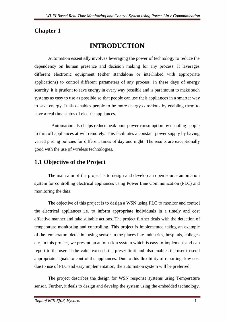
monitoring the data [1]. The experimental setup is as shown in the block diagram in
Fig 1.1. Control messages are sent over Wi-Fi network from a Wi-Fi device to the PC
which then couples the messages to the power lines using the micro controller with the
serial port interface. Ubiquitous power lines are used as physical media to transmit data
over 220V/50Hz signal to control appliances/equipment and to monitor.
Fig 1.1 Block diagram of Remote Monitoring and Control System
Here we are monitoring the temperature and when this crosses the set limit the
data is sent back to the PC and this will send the data to the cell phone and the user can
get to know the temp details. The data from the microcontroller is coupled onto the power
lines using a PLC modem and DCSK (Differential Code Shift Keying) modulation
technique is employed to transmit data. The receiver unit consists of PLC modem plus
microcontroller and can be connected anywhere in the power line network. The receivers
Page 3
WI-FI Based Real Time Monitoring and Control System using Power Lin e Communication
Dept of ECE, SJCE, Mysore. 3
have addresses assigned to them and only respond to the commands sent to them by the
transmitter PLC modem. The receiver unit controls the flow of electricity to the socket.
1.3 Scope of the Project
The proposed project aims at ensuring good monitoring and control of various
industrial parameters. It provides a good automation system as it sends a warning
message when the parameters exceed the preset limits. Also the system provides an easy
access to either switch on/off the device based on the value of the parameter received.
This system will be advancement in the industry, and also of low cost, since information
can be transmitted through the existing power lines without having to rewire the system.
1.4 Organization of the Report
Rest of the thesis is organized as follows.
Chapter 2 describes about the literature survey taken from the papers published in IEEE
transactions and reputed websites related to the design and implementation of Wi-Fi
based real time monitoring and control system using PLC.
Chapter 3 explains about Communication Protocols like PLC, Wi-Fi and DSSS
Modulation.
Chapter 4 describes the hardware implementation PLC Module, PIC Microcontroller
18F458, Temperature sensor, Amplifier, MAX232, ULN2003, Relay and LCD.
Chapter 5 gives the explanation of software implementation, Embedded C, MPLAB,
JAVA basics and Flowcharts.
Chapter 6 describes the results, conclusion and scope for future work.
Appendix A gives the pin description and architecture of PIC18F458 microcontroller.
Appendix B describes the information about description and other details of LM35.
Appendix C explains the details about input voltage range and features of LM324.
Appendix D gives the information about typical operating circuit and features of
MAX232.
Appendix E gives the details of ULN2003
Appendix F gives the features of PLC.
Page 4
WI-FI Based Real Time Monitoring and Control System using Power Lin e Communication
Dept of ECE, SJCE, Mysore. 4
Chapter 2
LITERATURE SURVEY
2.1 A Remote Controller for Home and Office Appliances by
Telephone [5]
This paper describes the design and development of a phone -based remote
controller for home and office automation. The circuit is designed based on the Turkish
telephone standards and connected to the telephone network just like any normal
telephone sets. Any tone dialing Dual Tone Multiple Frequency (DTMF) telephone set or
hand-held tone dialer may be used to send commands to the control unit, and remotely
control a wide range of mains appliances in homes and offices. The designed circuit can
also detect user identification number for prevent non-authorized use of the control unit.
The feedback signal informs to the user about the results of commands.
2.2 Remote-Controlled Home Automation Systems with
different Network Technologies [6]
This paper describes an investigation into the potential for remote controlled
operation of home automation systems. It considers problems with their implementation,
discusses possible solutions through various network technologies and indicates how to
optimize the use of such systems. The home is an eternal, heterogeneous, distributed
computing environment (Greaves, 2002) which certainly requires a careful study before
developing any suitable Home Automation System (HAS) that will accomplish its
requirements. Nevertheless the latest attempts at introducing Home Automation Systems
in actual homes for all kinds of users are starting to be Successful thanks to the
continuous standardization process that is lowering the prices and making devices more
useful and easier to use for the end user. Even so several important issues are always to be
handled strictly before developing and installing a Home Automation System; factors like
security, reliability, usefulness, robustness and price are critical to determine if the final
product will accomplish the expected requirements.
Page 5
WI-FI Based Real Time Monitoring and Control System using Power Lin e Communication
Dept of ECE, SJCE, Mysore. 5
2.3 Remote Control of Electrical Appliances via Power Line [7]
The presented work deals with problems of data transfer via power line 230 V for
the purposes of remote control electrical appliances. The devices providing relative
communication via power li
ne for a one-family house were designed and assembled. The designed devices,
namely the input-output unit, PC interface and the GSM gate, work on a bus principle.
The bus is constructed by power line 230V. The designed devices are composed of the
AVR microcontrollers and their mutual communication via power line is provided by
TDA5051AT modem. Communication protocol, with which the devices work, was
developed so that it corresponds with hardware resolution of particular devices. The
particular devices were practically implemented and their activity was tested.
2.4 Street Public Light Control and Monitoring using PLC [8]
There may be tens of thousands of street lamps in the streets and along the
highways. To inspect each lamp to check if it is working is an arduous task. Isn't it nice to
have a system, which will automatically report if a lamp in a Public Lighting System has
broken down. The infrastructure required for such self-reporting function must be very
complicated and cost prohibitively high. It is not so, if ARCHNET power line
modems are used. The ARCHNET power line modem makes use of the power cable as a
communication medium and data communication can take place between two points on a
power line without the need of a dedicated signal wires. An ARCHNET power line
modem and a sensor connected at the power source of the street lamp of a public lighting
system can sense the current flow through the lamp, thus monitoring the operation of the
street lamp. If the lamp breaks down, the modem will report the address code of the lamp
report back to the monitoring station through the power cable. At the Public Lighting
control station, a signal will flash on the screen giving the location of the street lamp.
2.5 A Practical Intelligent Home System Based on PLC [9]
This paper presents a practical, cost-effective intelligent home system based on
power line communication, in which manual keypad control, speech control and
GSM/GPRS remote control are implemented. In this system, speech control is for old
men and handicapped people who are unable to operate home appliances. A focusing
Page 6
WI-FI Based Real Time Monitoring and Control System using Power Lin e Communication
Dept of ECE, SJCE, Mysore. 6
fuzzy template matching algorithm is proposed to improve the accuracy of speech
recognition under noisy background. GSM/GPRS remote control makes operation of
home appliances and home surveillance feasible anywhere. Because of the
implementation of power line communication technology, no rewiring is required, thus
making the installation of such system simple, low cost and efficient, which is favorable
for the popularization of intelligent home.
2.6 Wireless Networking for Sugar Industries through PLCC
Technique [10]
This paper discusses the new approach of parameters monitoring for drives
through Power Line Carrier Communication. Using this technique parameters likes speed,
voltage, current and power factors are monitored by using exceed power leads as a
communication media. The communication media are located in two different places for
sending and receiving the data which require existing 50Hz power line. This
communication circuit uses an asynchronous serial Communication protocol and an FSK
modulation for realizing frequency multiplexing in the power line. These monitoring
systems used for an inverter-fed induction machine are constructed using this power line
communication link. A prototype model was demonstrated satisfactory within the limited
distance.
2.7 Remote Data Acquisition Using Wireless SCADA System
[11]
This project has developed an integrated wireless SCADA system for monitoring
and accessing the performance of remotely situated device parameter such as temperature,
pressure, humidity on real time basis. For this the infrastructure of the existing mobile
network has been used, which is based on GPRS technique. Supervisory Control and Data
Acquisition (SCADA) is a field of constant development and research. This project
investigates on creating an extremely low cost device which can be adapted to many
different SCADA applications via some very basic programming and plugging in the
relevant peripherals. Much of the price in some expensive SCADA applications is a result
of using specialized communication infrastructure. The application of existing
infrastructure in the proposed scheme will reduce the cost. Additionally the generic nature
of the device will be assured.
Page 7
WI-FI Based Real Time Monitoring and Control System using Power Lin e Communication
Dept of ECE, SJCE, Mysore. 7
Chapter 3
COMMUNICATION PROTOCOLS
This chapter gives the details of different communication protocols like PLC,
Wi-Fi and DSSS modulation techniques.
3.1 Power Line Communication System
Power line communication or power line carrier (PLC), also known as power line
digital subscriber line (PDSL), mains communication, power line telecom (PLT), power
line networking (PLN), or broadband over power lines (BPL) are systems for carrying
data on a conductor also used for electric power transmission.
A wide range of power line communication technologies are needed for different
applications, ranging from home automation to Internet access. Electrical power is
transmitted over long distances using high voltage transmission lines, distributed over
medium voltages, and used inside buildings at lower voltages. Most PLC technologies
limit themselves to one set of wires (such as premises wiring within a single building),
but some can cross between two levels (for example, both the distribution network and
premises wiring). Typically transformers prevent propagating the signal, which requires
multiple technologies to form very large networks. Various data rates and frequencies are
used in different situations. A number of difficult technical problems are common
between wireless and power line communication, notably those of spread spectrum radio
signals operating in a crowded environment. Potential interference, for example, has long
been a concern of amateur radio groups.
Power line communications systems operate by impressing a modulated carrier
signal on the wiring system. Different types of power line communications use different
frequency bands, depending on the signal transmission characteristics of the power wiring
used. Since the power distribution system was originally intended for transmission of AC
power at typical frequencies of 50 or 60Hz, power wire circuits have only a limited ability
to carry higher frequencies. The propagation problem is a limiting factor for each type of
power line communications.
Page 8
WI-FI Based Real Time Monitoring and Control System using Power Lin e Communication
Dept of ECE, SJCE, Mysore. 8
Data rates and distance limits vary widely over many power line communication
standards. Low-frequency (about 100–200 kHz) carriers impressed on high-voltage
transmission lines may carry one or two analog voice circuits, or telemetry and control
circuits with an equivalent data rate of a few hundred bits per second; however, these
circuits may be many miles long. Higher data rates generally imply shorter ranges; a local
area network operating at millions of bits per second may only cover one floor of an
office building, but eliminates the need for installation of dedicated network cabling.
3.1.1 ATL90 Series PLC Modem
ATL90 series Embedded PLC modem series is based on the Direct Sequence
Spread Spectrum Technology. The new technology in Power Line Carrier
Communication (PLCC) is well known for its high immunity to electrical noise persistent
in the power line. With the new solution, the form factor of the PLC modem is further
reduced and its cost lowered [2].
The Embedded PLC Modem is in the form of a ready-to-go circuit module, which
is capable of transferring data over the power cable at the low voltage end of the power
transformer of a 3-phase/ 4-wire distribution network. A pair of Embedded PLC Modems
connected on the power line can provide low speed bi-directional data communication at
a baud rate of 300/600 bps. It is built in a small form factor that can be easily integrated
into and become part of the user's power line data communication system.
3.1.2 Block Diagram of PLC Modem
The operation of the PLC Modem can be better understood by its block diagram.
Fig 3.1 shows the General Block Diagram of the ATL90 series PLC Modem.
A Power Line Communication Modem system begins with a modulated signal
entering the receiver stage, or active band pass filter where the op-amp selected for the
filter should provide low noise, low harmonic distortion, and low input bias as seen in
TI’s OPA365 or OPA353. Scaling the received signal by using a Programmable Gain
Amplifier (PGA) such as the PGA112 allows for a wide dynamic range and optimal
signal processing. It needs to connect to the input of an Analog to Digital Converter fast
and accurate enough to properly convert to a digital form for processing. This is done
Page 9
WI-FI Based Real Time Monitoring and Control System using Power Lin e Communication
Dept of ECE, SJCE, Mysore. 9
thanks to the on–chip 12-bit ADC of the F28235 Delfino™ or F2802x/03x Piccolo™
microcontroller member of the scalable C2000™ 32-bit microcontroller (MCU) family.
The 12-bit ADC operates at up to 12.5 MSPS and also includes triggering
mechanisms for support of multi-frequency and phase sampling (2 sample and hold
functions). The C2000™ MCU family then enables developers to support multiple
modulations on the same hardware, thus eliminating the need to redesign the modem to
support different modulation or standards. This makes the C2000™ 32-bit MCU family a
smart and flexible platform for Power Line Communication implementation.
Fig 3.1 General Block Diagram of PLC Modem
Processed signals are injected back into the power grid by the PLC transmitter
stage that drives a high output current. The control can be done using the C2000 PWMs
support duty cycle resolution down to 150 ps to enable more control over harmonics and
reduce sample-to-output delay. The transmitter stage must be carefully designed to take
digital signals from the MCU, filter them to eliminate out of band emissions and drive the
low impedance of the AC power line. The OPA564 is a 24V, 1.5A, 17 MHz power op-
amp designed for the rigorous demands of the PLC line driver. Further improvements in
integration, performance and cost can be realized when combining the AFE031, a highly
Page 10
WI-FI Based Real Time Monitoring and Control System using Power Lin e Communication
Dept of ECE, SJCE, Mysore. 10
integrated PLC Analog Front End with the C20000TM. The AFE031 integrates the
transmit filter, power amplifier, receive filter and PGA in a programmable integrated
circuit designed just for PLC.
The resulting modem MCU + AFE can directly communicate with outside
systems (both wired and wireless applications) via one of C2000TM serial interface
options including CAN, I2C, LIN, SPI or UART. TI PLC software is delivered in the
PLC Suite library and enables developers to support several modulations and standards on
one unique design. Developers can implement SFSK IEC61334, PRIME and G3
standards as well as Flex OFDM for custom OFDM implementation and is scalable for
the incoming standards.
From the power management perspective, the PLC module can take its power
from existing system DC rails or directly from the mains AC power it is communicating
over. In the case of the latter, 115V, 60Hz in the U.S. (or 230V, 50Hz in Europe and
Asia) needs to be filtered and converted to isolated DC power for the MCU, AFE and
various support components. The UCC28600 or UCC28610 Fly back Green-Mode
Controller is ideal for providing an isolated 12V or 15V DC rail that can be used directly
for the power amplifier and into a DCDC module, such as the PTH08080W, or buck
converter, such as the TPS54231, to provide low voltage (5V) PLC system rail. The
addition of a linear regulator such as the TPS79533 LDO can provide a low-noise 3.3V
rail for use by low power components such as the MCU, PGA, op amps, USB
transceivers, and any additional digital or analog components.
3.1.3 Features of PLC Modem
Some of the features of PLC modem are as follows:
Embedded ready-to-go Power Line Carrier Modem module with SMT
components.
Small form factor for easy of system integration.
Bi-directional half-duplex data communication over the mains.
Applicable to universal mains voltage and frequency up to 250V, 50 - 60 Hz.
Protocol independent, data transfer transparent to user's data terminals.
High noise immunity and reliable data communication.
Page 11
WI-FI Based Real Time Monitoring and Control System using Power Lin e Communication
Dept of ECE, SJCE, Mysore. 11
Simple serial interface to user's data devices.
Built-in on board AC coupling circuit with direct connection to mains.
Built-in carrier generation and detection.
Baud rate of 300/600 bps.
Selectable TTL and RS232C level serial interface to user's data devices.
Built with industrial grade components for operation under harsh environment.
3.1.4 Applications of the PLC
Some of the important applications of the PLC are
Home Automation
Automatic Meter Reading
Process Control
Heating and Ventilation Control
Air Conditioning Control
Lighting Control
Status Monitoring and Control
Intelligent Buildings
Fire and Security Alarm System
Power Distribution Management
3.2 Wireless Communication
Wireless communication is used to transfer information over short distance of a
few meters as in TV (Tele Vision) remote control or long distance thousands of millions
of km for radio communication. The term is often shortened to wireless. It encompasses
various types of fixed, and portable two way radios, cellular telephone, Personal Digital
Assistant (PDAs) and wireless networking, other examples of wireless networking
includes GPS (Global Positioning Systems) units garage door openers, wireless computer
mouse, keyboard and handsets, satellite TV and cordless telephones. Its operation permits
service such as long range communication that is impossible or impractical to implement
with the use of wires. The term is commonly used in telecommunication industry to refer
Page 12
WI-FI Based Real Time Monitoring and Control System using Power Lin e Communication
Dept of ECE, SJCE, Mysore. 12
telecommunication system for example radio transmitter and receiver, remote controllers
which use some form of energy for example radio frequency, Infrared light, laser light to
transfer information without the use of wires. Information is transferred in this manner
over both short and long distance. In our project we are using Wi-Fi as a wireless
communication.
3.2.1 Wi-Fi
Wi-Fi is a popular technology that allows an electronic device to exchange data
wirelessly using radio waves over a computer network, including high speed internet
connections.
3.2.2 Working of Wi-Fi
Radio waves are used for the working of Wi-Fi technology. The Wi-Fi network's
most common encryption module named as wired equivalent privacy is considered to be
the safest. The use and access to Wi-Fi network is really simple. The wireless adapter of
the computer and the wireless router play an important role in its working. The adapter
receives data from the computer in digital form. This data, after its conversion in radio
waves is sent to the router by means of an antenna. The router decodes the signal and
sends it to the internet. The process is reversed when information is sent from the internet
to a computer. The difference between the radio waves sent by Wi-Fi and those sent by
walkie-talkies and cell phones is that Wi-Fi uses high frequency waves.
3.2.3 Wi-Fi Working in Laptop or Desktop
There are three most important items which makes Wi-Fi working in laptop or
desktop. These are
Fig 3.2: Wi-Fi Working
Page 13
WI-FI Based Real Time Monitoring and Control System using Power Lin e Communication
Dept of ECE, SJCE, Mysore. 13
1. Radio Signals
2. Wi-Fi Card which fits in laptop or computer
3. Hotspots which create Wi-Fi Network
Radio Signals: Radio Signals are the keys which make Wi-Fi networking possible.
These radio signals transmitted from Wi-Fi antennas are picked up by Wi-Fi receivers
such as computers and cell phones that are equipped with Wi-Fi cards. Whenever a
computer receives any signals within the range of a Wi-Fi network which is usually 300-
500 feet for antennas, the Wi-Fi card will read the signals and thus create an internet
connection between the user and the network without the use of a cord.
Access points which consist of antennas and routers are the main source which
transmit and receive radio waves. Antennas work stronger and have a longer radio
transmission with a radius of 300-500 feet which are used in public areas while the
weaker yet effective router is more suitable for homes with a radio transmission of 100-
150 feet.
Wi-Fi Cards: Wi-Fi card as being an invisible cord that connects computer to the
antenna for a direct connection to the internet. Wi-Fi cards can be external or internal,
meaning that if a Wi-Fi card is not installed in a computer, USB antenna attachment has
to be purchase and have it externally connect to USB port, or have an antenna-equipped
expansion card installed directly to the computer. For laptops, this card will be a Personal
Computer Memory Card International Association (PCMCIA) card in which you insert to
the PCMCIA slot on the laptop.
Wi-Fi Hotspots: A Wi-Fi hotspot is created by installing an access point to an internet
connection. The access point transmits a wireless signal over a short distance, typically
covering around 300 feet. When a Wi-Fi enabled device, such as a pocket PC, encounters
a hotspot, the device can then connect to that network wirelessly. Most hotspots are
located in places that are readily accessible to the public like airports, coffee shops,
hotels, book stores and campus environments. 802.11b is the most common specification
for hotspots worldwide. The 802.11g standard is backwards compatible with .11b but .11a
uses a different frequency range and requires separate hardware such as an a, a/g, or a/b/g
Page 14
WI-FI Based Real Time Monitoring and Control System using Power Lin e Communication
Dept of ECE, SJCE, Mysore. 14
adapter. The largest public Wi-Fi networks are provided by private Internet Service
Providers (ISPs) that charge a fee for users to connect to the internet.
Any notebook computer with integrated wireless, a wireless adapter attached to
the motherboard by the manufacturer, or a wireless adapter such as a PCMCIA card can
access a wireless network. Furthermore, all pocket PCs or palm units with compact flash,
SD I/O support, or built-in Wi-Fi, can access hotspots. Some Hotspots require Wireless
Encryption Protocol (WEP) key to connect that is the connection is considered to be
private or secure. As for open connections, anyone with a Wi-Fi card can gain access to
that hotspot. So in order for a user to gain access to the internet under WEP, the user must
input the WEP key code.
3.2.4 Communication ranges
Wi-Fi networks have limited range. A typical wireless access point using 802.11b
or 802.11g with a stock antenna might have a range of 32m (120 ft) indoors and 95m
(300 ft) outdoors. Range also varies with frequency band. Wi-Fi in the 2.4GHz frequency
block has slightly better range than Wi-Fi in the 5GHz frequency block which is used by
802.11a. On wireless routers with detachable antennas, it is possible to improve range by
fitting upgraded antennas which have higher gain in particular directions. Outdoor ranges
can be improved to many kilometers through the use of high gain directional antennas at
the router and remote devices. Due to reach requirements for wireless LAN applications,
Wi-Fi has fairly high power consumption compared to some other standards.
Technologies such as Bluetooth designed to support wireless PAN applications
provide a much shorter propagation range of less than 10m and so in general have lower
power consumption. Other low-power technologies such as Zigbee have fairly long range,
but much lower data rate. The high power consumption of Wi-Fi makes battery life in
mobile devices a concern.
3.2.5 Advantages of Wi-Fi
Following are the advantages of Wi-Fi
1. Wi-Fi allows cheaper deployment of Local Area Networks (LANs). Also spaces
where cables cannot be run, such as outdoor areas and historical buildings, can
host wireless LANs.
Page 15
WI-FI Based Real Time Monitoring and Control System using Power Lin e Communication
Dept of ECE, SJCE, Mysore. 15
2. Manufacturers are building wireless network adapters into most laptops. The price
of chipsets for Wi-Fi continues to drop, making it an economical networking
option included in even more devices.
3. Wi-Fi Protected Access encryption (WPA2) is considered secure, provided a
strong passphrase is used. New protocols for quality of service make Wi-Fi more
suitable for latency sensitive applications such as voice and video. Powers saving
mechanisms extend battery life.
3.2.6 Sockets protocol
In computer networking, an Internet socket or network socket is an endpoint of a
bidirectional inter-process communication flow across an internet protocol based
computer network, such as the internet. The Fig 3.3 below shows the socket connection.
Fig 3.3: Block Diagram Showing Communication through Sockets
The term Internet socket is also used as a name for an application programming
interface (API) for the TCP/IP protocol stack, usually provided by the operating system.
Internet sockets constitute a mechanism for delivering incoming data packets to the
appropriate application process or thread, based on a combination of local and remote IP
addresses and port numbers. Each socket is mapped by the operating system to a
communicating application process or thread.
A socket address is the combination of an IP address (the location of the
computer) and a port (which is mapped to the application program process) into a single
identity, much like one end of a telephone connection is the combination of a phone
number and a particular extension. An Internet socket is characterized by a unique
combination of the following: Local socket address, Local IP addresses and port number.
Remote socket address is used for establishing TCP sockets. As discussed in the Client-
Server section below, this is necessary since a TCP server may serve several clients
concurrently. The server creates one socket for each client, and these sockets share the
same local socket address.
Page 16
WI-FI Based Real Time Monitoring and Control System using Power Lin e Communication
Dept of ECE, SJCE, Mysore. 16
The term socket refers to an entity that is uniquely identified by the socket
number. In other sense, the socket term refers to a local socket address, i.e. a
"combination of an IP address and a port number". In the original definition
of socket given in RFC 147, as it was related to the ARPA network in 1971, the socket is
specified as a 32 bit number with even sockets identifying receiving sockets and odd
sockets identifying sending sockets. Today however, socket communications are
bidirectional. On UNIX and Microsoft Windows based operating systems the net state
command line tool may be used to list all currently established sockets and related
information.
3.3 DSSS Modulation
Direct Sequence Spread Spectrum (DSSS) as shown in Figure 3.4, is a spread
spectrum technique whereby the original data signal is multiplied with a pseudo random
noise spreading code. This spreading code has a higher chip rate (the bit rate of the
code), which results in a wideband time continuous scrambled signal.
Fig 3.4: Direct Sequence Spread Spectrum
DSSS significantly improves protection against interfering (or jamming) signals,
especially narrowband and makes the signal less noticeable. It also provides security of
transmission if the code is not known to the public. These reasons make DSSS very
popular by the military. In fact, DSSS was first used in the 1940s by the military.
DSSS can also be used as a multiple access technique, whereby several different pseudo
random spreading codes are being used simultaneously. This multiple access technique
is better known as Direct Sequence CDMA.
Page 17
WI-FI Based Real Time Monitoring and Control System using Power Lin e Communication
Dept of ECE, SJCE, Mysore. 17
Chapter 4
HARDWARE IMPLEMENTATION
This chapter deals with the working principle of project and hardware description
of PIC microcontroller, PLC modem, Temperature sensor, Amplifier, MAX232, Relay,
LCD and ULN2003.
4.1 Principle of Operation
A Wi-Fi enabled device is used as means of input. A Cell phone with Wi-Fi &
Android based is used for this purpose, which provides the user with a touch screen
interface facilitating ease of use. A Wi-Fi network is first setup using a wireless router.
The PC connects to the PLC Modem through a RS232 interface. An application on the
device consists of keypad that enables us to send signals to the PC through Wi-Fi.
These signals are sent to PLC modem. When a user presses a particular number,
specific messages are sent over the Wi-Fi network to the PLC modem through PC .
PLC modem transmits data signals through the existing power lines to the other side
PLC Modem.
Fig 4.1 Block diagram of Wi-Fi based real time Monitoring and Control system
Using PLC.
Page 18
WI-FI Based Real Time Monitoring and Control System using Power Lin e Communication
Dept of ECE, SJCE, Mysore. 18
PLC modem sends this data signals to the PIC Microcontroller. The
microcontroller converts these messages into simple control signals. The commands sent
by the microcontroller to switch ON/OFF an appliance are not sent directly to the
appliance, but rather these commands are broadcasted over the power lines using a
PLC transmitter. The microcontroller sends data to the PLC modem using UART
protocol. Each end appliance has a PLC receiver plus microcontroller combination to
listen to these commands, if the commands are intended to the corresponding appliance;
it switches ON/OFF the appliance. Fig 4.1 shows the block diagram of Wi-Fi based real
time Monitoring and Control system using PLC.
On the other hand if the parameters of a particular appliance exceed a threshold
or preset limit then the microcontroller sends data signal to the PLC modem using
UART Protocol. The PLC modem on the other side receives this signal through the
existing Power lines. These signals are sent to the PC through RS232 interface. PC will
send information to the cell phone via Wi-Fi for monitoring parameters. Here we are
monitoring the temperature and when this crosses the set limit the data is sent back to the
PC and this will send the data to the cell phone through Wi-Fi and the user can get to
know the temperature details.
4.2 Hardware Description
The following sections briefly describe the hardware components used in this project.
4.2.1 PLC Modem ATL90115-1
The ATL90115 series Embedded PLC Modem is a ready to go circuit module,
which is capable of transferring data over the power cable at the low voltage end of
the power transformer of a 3-phase/ 4-wire distribution network. Fig 4.2 shows PLC
Modem ATL90115-1 used in the project.
Fig 4.2 PLC Modem ATL90115-1
Page 19
WI-FI Based Real Time Monitoring and Control System using Power Lin e Communication
Dept of ECE, SJCE, Mysore. 19
A pair of Embedded PLC Modems connected on the power line can provide low
speed bi-directional data communication at a baud rate of 300 bps. It is built in a small
form factor that can be easily integrated into and become part of the user's power line data
communication system. The PLC modem is based on the Direct Sequence Spread
Spectrum Technology, which ensures high noise immunity and reliable data
communication.
Fig 4.3 ATL90115-1 Application Diagram
Application Diagram for the single phase of the ATL90115 is shown in Fig 4.3.
This PLC Module provides bi-directional half-duplex data communication over the mains
of any voltage up to 250V AC, and for frequency of 50 or 60 Hz. It does not require any
protocol to function and therefore is protocol independent.
Data flow through PLC modem as if it is a channel and therefore it is transparent
to the Data Devices. As a result, with user’s proper addressing and communication
protocol, multiple units can be connected to the mains without affecting the operation of
one another. There is no hassle of building interface circuits. It has a built-in onboard AC
coupling circuit, which allows direct and simple connection to the mains. Interface to
user’s data devices is a simple data -in and data-out serial link. Power to the PLC Modem
circuit module is a single +12v DC supply.
4.2.2 PIC Microcontroller
The microcontroller used for his system is PIC 18F458. Fig 4.4 shows PIC18F458
Pin details. The PIC families of microcontrollers are developed by microchip Technology
Inc [3].
Features
The CPU uses Harvard architecture with separate program and variable (data) memory
Page 20
WI-FI Based Real Time Monitoring and Control System using Power Lin e Communication
Dept of ECE, SJCE, Mysore. 20
interface. This facilitates instruction fetch and the operation on data accessing of variables
simultaneously. Basically, all PIC microcontrollers offer the following features:
RISC instruction set
On-chip timer with 8 bit prescaler
Power on reset
Watchdog timer
Power saving SLEEP Mode
Direct, indirect and relative addressing modes
External clock interface
RAM data memory
EPROM Program memory
Some devices offer the following additional features:
Analogue input channels
Analogue comparators
Additional timer circuits
EEPROM data memory
Flash EEPROM program memory
External and timer interrupts
USART serial interface
Internal oscillator
Pin Description:
PIC18F458 is a 40 pin microcontroller. It has 5 ports Port A, port B, port C, port D, port E.
All the pins of the ports for interfacing input output devices.
Port A [Analog]: It consists of 6 pins from A0 to A5
Port B [Interrupt]: It consists of 8 pins from B0 to B7
Port C [serial communication]: It consists of 8 pins from C0 to C7
Port D [LCD]: It consists of 8 pins from D0 to D7
Page 21
WI-FI Based Real Time Monitoring and Control System using Power Lin e Communication
Dept of ECE, SJCE, Mysore. 21
Port E [Enable]: It consists of 3pins from E0 to E2
The rest of the pins are mandatory pins these should not be used to connect input/output
devices.
Pin 1 is MCLR (master clear pin) also referred as reset pin.
Pin 13, 14 are used for connecting the crystal oscillator to generate a frequency of about
20MHz.
Fig 4.4 PIC 18F458 Pin Details
4.2.2.1 Analog to Digital converter (ADC):
External signals are usually fundamentally different from those the
microcontroller understands (zero and one); so that they have to be converted in order the
microcontroller can understand them.
An analog-to digital converter is an electronic circuit which converts continuous
signals to discrete digital numbers. This module is therefore used to convert some analog
value into binary number and forwards it to the CPU for further processing. In other
words, this module is used for input pin voltage measurement (analog value). The result
of measurement is a number (digital value) used and processed later in the program.
Page 22
WI-FI Based Real Time Monitoring and Control System using Power Lin e Communication
Dept of ECE, SJCE, Mysore. 22
The Analog-to-Digital (A/D) Converter module has five inputs for the
PIC18F2X8 devices and eight for the PIC18F4X8 devices. This module has the
ADCON0 and ADCON1 register definitions that are compatible with the PICmicro®
mid-range A/D module. The A/D allows conversion of an analog input signal to a
corresponding 10-bit digital number.
4.2.2.2 UART
A universal asynchronous receiver/transmitter, abbreviated UART, is a type of
"asynchronous receiver/transmitter", a piece of computer hardware that translates data
between parallel and serial forms. For serial data transfer UART is often used because of its
simple design. Serial transmission is commonly used with modems and for non-networked
communication between computers, terminals and other devices. There are two primary
forms of serial transmission Synchronous and Asynchronous.
The device changes parallel information to serial, which can be sent on
communication line. The UART usually does not directly generate or receive the external
signals used between different items of equipment. Separate interface devices are used to
convert the logic level signals of the UART to and from the external signaling levels.
External signals may be of many different forms. Examples of standards for voltage
signaling are RS-232, RS-422 and RS-485 from the EIA. In UART we are using a standard
protocol i.e. RS-232.
4.2.2.3 Liquid Crystal Display
A liquid crystal display is a thin, flat display device as shown in Fig 4.5 is made
up of many number of color or monochrome pixels arrayed in front of a light source or
reflector and it consumes very low power which makes it user compatible. Each pixel of
LCD consists of a column of liquid crystal molecules suspended between two transparent
electrodes, and two polarizing filters, the axes of polarity of which are perpendicular to
each other.
The liquid crystal twists the polarization of light entering through one filter to
allow it to pass through the other filter. For an 8-bit data bus, the display requires a +5V
Page 23
WI-FI Based Real Time Monitoring and Control System using Power Lin e Communication
Dept of ECE, SJCE, Mysore. 23
supply and 11 I/O lines. When the LCD display is not enabled, data lines are tri-state and
they do not interfere with the operation of the microcontroller.
Fig 4.5 Pin Details of 16x2 line LCD
There are three signals in the LCD: Enable, Read/Write and Register select.
1. Enable (E): This line allows access to the display through R/W and RS lines.
When this line is low, the LCD is disabled and when it is high, the LCD checks
the state of the two control lines and responds accordingly.
2. Read/Write (R/W): This line determines the direction of data between the LCD
and microcontroller and when it is low, data is written to the LCD. When it is
high, data is read from the LCD.
3. Register Select (RS): With the help of this line, the LCD interprets the type of data
on data lines and when it is low, an instruction is being written to the LCD. When
it is high, a character is being written to the LCD.
Page 24
WI-FI Based Real Time Monitoring and Control System using Power Lin e Communication
Dept of ECE, SJCE, Mysore. 24
4.2.3 RS232
RS232 (Recommended Standard 232) is the traditional name for a serial binary
single ended data and control signal connecting between a DTE (Data Terminal
Equipment) and a DCE (Data Circuit terminating Equipment) this defines each device
which wires will be sending and receiving each signal.
Table 4.1 RS232 Logic Levels
RS232 Line Type & Logic Level RS232 Voltage TTL Voltage
to/from MAX232
Data Transmission (Rx/Tx) Logic 0 +3 V to +15 V 0 V
Data Transmission (Rx/Tx) Logic 1 -3 V to -15 V 5 V
Control Signals
(RTS/CTS/DTR/DSR) Logic 0 -3 V to -15 V 5 V
Control Signals
(RTS/CTS/DTR/DSR) Logic 1 +3 V to +15 V 0 V
4.
The standard defines the electrical characteristics and timing of signals, the
meaning of signals, and the physical size and pin out of connectors. The RS232 standard
defines the voltage levels that corresponding to logical one and logical zero levels for the
data transmission and the control signal lines. The Table 4.1 shows the RS232 logic
levels.
Fig 4.6 RS232 Pin Diagram
The standard specifies a maximum open circuit voltage of 25 V, signal levels of
+/- 5 V, +/-10 V, +/- 12 V, and +/- 15 V are all commonly seen depending on the power
supplies available within device. Fig 4.6 shows the 9 pin configuration of RS232. The
standard defines the electrical characteristics and timing of signals, the meaning of
signals, and the physical size and pin out of connections. RS232 drivers and receivers
Page 25
WI-FI Based Real Time Monitoring and Control System using Power Lin e Communication
Dept of ECE, SJCE, Mysore. 25
must be able to withstand indefinite short circuit to ground or to any voltage level up to
+/- 25 V. Both synchronous and asynchronous transmissions are supported.
4.2.4 MAX232
The MAX232 from maxim was the first IC which is one package contains
the necessary drivers and receivers, to adapt the RS232 signal voltage levels to TTL logic.
It became popular, because it just needs +5 V and generates the necessary RS232 voltage
levels. The pin configuration of MAX232 is shown in Fig 4.7. In serial communication
the line that is used to transmit data is called Tx and the line used to receive data is called
Rx. The PIC Microcontroller uses TTL level for logic that is a 1 is a 5 V and 0 is 0 V but
RS232 standard uses different scheme for logic level, so we need a level converter in
between. The data is ready to be fed to a standard serial port of PC. All good development
boards have an on board level converter. The MAX 232 IC is a industry standard chip for
the purpose of level conversion between RS232 and TTL signals. Serial cable has been
used to connect the MAX232 to PC.
Fig 4.7 Pin Configuration of MAX232
Serial cable has male and female DB9 connector. Pin 13 and 8 of MAX232 have
been connected to DB9 port in order to transfer information to the computer. Pins 12 and
9 on the MAX232 have been connected to PIC, port C pin C6 and C7 in order to transfer
information signals to PIC. The voltage supply of 5V for Max232 can be achieved
through the schematic circuit which has standard capacitance.
Voltage Levels
It is helpful to understand what occurs to the voltage levels. When a MAX232 IC
receives a TTL level to convert, it changes a TTL Logic 0 to between +3 and +15 V, and
changes TTL Logic 1 to between -3 to -15 V, and vice versa for converting from RS232
Page 26
WI-FI Based Real Time Monitoring and Control System using Power Lin e Communication
Dept of ECE, SJCE, Mysore. 26
to TTL. The different voltage levels as shown in Table 4.1 of RS-232 and TTL voltage to
and from MAX232. This can be confusing when one realize that the RS-232 Data
Transmission voltages at a certain logic state are opposite from the RS-232 Control Line
voltages at the same logic state.
For data transmission lines TXD, RXD and their secondary channel equivalents
logic one is defined as a negative voltage and the signal condition is called marking.
Logic zero is defined as positive and the signal condition is termed spacing. Control
signals are logically inverted with respect to what one sees on the data transmission lines.
When one of these signals is active, the voltage on the line will be between +3 to +15
volts and the inactive state for these signals is the opposite voltage condition, between −3
and −15 volts. The voltage levels are higher than logic levels typically used by integrated
circuits, special intervening driver circuits are required to translate logic levels and also
protect the device's internal circuitry from short circuits or transients.
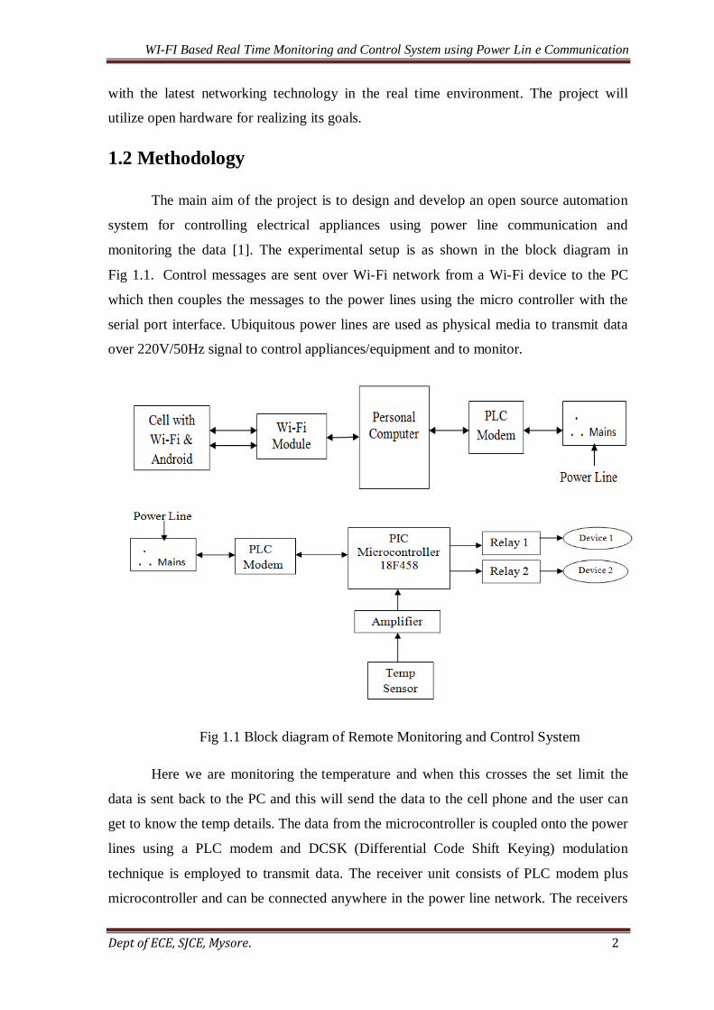
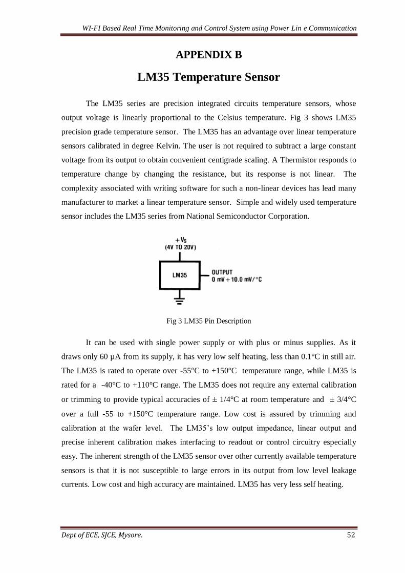
4.2.5 LM35 Temperature Sensor
The LM35 series are precision integrated circuit temperature sensor is shown in
the Fig.4.8 whose output voltage is linearly proportional to the Celsius temperature. The
LM35 thus has an advantage over linear temperature sensors calibrated in Kelvin, as the
user is not required to subtract a large constant voltage from its output to obtain
convenient Centigrade scaling. The LM35 does not require any external calibration or
trimming to provide typical accuracies of ±1⁄4°C at room temperature and ±3⁄4°C over a
full −55 to +150°C temperature range. Low cost is assured by trimming and calibration at
the wafer level.
Fig 4.8 Temperature Sensor LM35
LM35 can be applied easily in the same way as other integrated circuit
temperature sensors. It can be glued or cemented to a surface and its temperature will be
within about 0.01°C of the surface temperature. This presumes that the ambient air
LM
35
Vcc O/P Gnd
Page 27
WI-FI Based Real Time Monitoring and Control System using Power Lin e Communication
Dept of ECE, SJCE, Mysore. 27
temperature is almost the same as the surface temperature; if the air temperature were
much higher or lower than the surface temperature, the actual temperature of the LM35
would be an intermediate temperature between the surface temperature and the air
temperature. The copper leads are the principal thermal path to carry heat in the devices,
so its temperature might be close to the air temperature than to the surface temperature.
The LM35’s low output impedance, linear output, and precise inherent calibration make
interfacing to readout or control circuitry especially easy. It can be used with single
power supplies, or with plus and minus supplies.
As it draws only 60 μA from its supply, it has very low self heating, less than
0.1°C in still air. The LM35 is rated to operate over a −55° to +150°C temperature range,
while the LM35C is rated for a −40° to +110°C range. The LM35 series is available
packaged in hermetic TO-46 transistor packages, while the LM35C, LM35CA, and
LM35D are also available in the plastic TO-92 transistor package. To minimize this
problem, the wiring to the LM35 as it leaves the devices, held is at the same temperature
as the surface of interest. The easiest way to do this is to cover up these wires with a bead
of epoxy, which will insure that the leads and wires are all the same temperature as the
surface and that the LM35’s temperature is not affected by the air.
The LM35 can be applied easily in the same way as other integrated-circuit
temperature sensors. It can be glued or cemented to a surface and its temperature will be
within about 0.01°C of the surface temperature. If the air temperature were much higher
or lower than the surface temperature, the actual temperature of the LM35 die would be at
an intermediate temperature between the surface temperature and the air temperature.
This is especially true for the TO-92 plastic package, where the copper leads are the
principal thermal path to carry heat into the device, so its temperature might be closer to
the air temperature than to the surface temperature. Alternatively, LM35 mounted can be
inside a sealed end metal tube and is then dipped into a bath or screwed into a threaded
hole in a tank. The LM35 and accompanying wiring and circuits must be kept insulated
and deep, to avoid leakage and corrosion. This is especially true if the circuit coatings and
varnishes such as epoxy paints or dips often used are to insure that moisture cannot
corrode the LM35 or its connections.
Page 28
WI-FI Based Real Time Monitoring and Control System using Power Lin e Communication
Dept of ECE, SJCE, Mysore. 28
4.2.6 LM324 Operational Amplifier
The LM324 series are low cost, quad operational amplifiers with true differential
inputs. They have several distinct advantages over standard operational amplifier types in
single supply applications. The quad amplifier can operate at supply voltages as low as
3.0V or as high as 32V with quiescent currents about one fifth of those associated. The
common mode input range includes the negative supply, thereby eliminating the necessity
for external biasing components in many applications. The output voltage range also
includes the negative power supply voltage.
In the linear mode, the input common mode voltage range includes ground and the
output voltage can also swing to ground, even though operated from only a single power
supply voltage. The unity gain crossover frequency and the input bias current are
Temperature compensated. LM324 has large dc voltage gain up to 100 dB, wide
bandwidth is about 1MHz. It has Wide power supply range Single supply 3Vdc to 30Vdc
and Low input biasing current and offset voltage. True Differential input stage is
considered, and is internally compensated.
The LM324 consists of four independent, high-gain, internally frequency-
compensated operational amplifiers designed specifically to operate from a single power
supply over a wide range of voltages. The LM324 series is made using four internally
compensated, two stage operational amplifiers. Another feature of this input stage is that
the input common mode range can include the negative supply, in single supply
operation, without saturating either the input devices or the differential to single ended
converter.
Fig 4.9: Pin Description of LM324
Page 29
WI-FI Based Real Time Monitoring and Control System using Power Lin e Communication
Dept of ECE, SJCE, Mysore. 29
Pin description of LM324 is as shown in Fig 4.9. The first stage consists of
differential input devices Q20 and Q18 with input buffer transistors Q21 and Q17 and the
differential to single ended converter Q3 and Q4. The first stage performs not only the
first stage gain function but also performs the level shifting and transconductance
reduction functions. By reducing the transconductance, a smaller compensation capacitor
can be employed, thus saving chip area. The transconductance reduction is accomplished
by splitting the collectors of Q20 and Q18.
4.2.7 ULN2003
The ULN2003 is a high voltage and high current Darlington transistor array. It
consists of seven NPN Darlington pairs that feature high voltage output with common
cathode clamp diodes for switching inductive loads. The collector current rating of a
single Darlington pairs is 50 mA. The Darlington pairs can be paralleled for higher
current capability. Applications include relay drivers, hammer drivers, lamp drivers,
display drivers and logic buffer. Fig 4.10 shows the pin configuration of ULN2003.
Fig 4.10 Pin Diagram of ULN2003
The key features of ULN2003 are 500 mA rated collector current (single output),
high voltage output, and output clamp diodes and input compatible with various type of
logic and relay driver applications. A Darlington pairs consists of two transistors which
are connected in series, output of one transistor drives the other transistors. The
amplification done at one transistor is enhanced by other transistor. Fig 4.11 shows
Darlington pairs.
The seven NPN Darlington connected transistors in these arrays are well suited for
driving lamps, relays, or printer hammers in a variety of industrial and consumer
Page 30
WI-FI Based Real Time Monitoring and Control System using Power Lin e Communication
Dept of ECE, SJCE, Mysore. 30
applications. Their high breakdown voltage and internal suppression diodes insure
freedom from problems associated with inductive loads. Peak inrush currents to 500 mA
permit them to drive incandescent lamps. The ULx2003A with a 2.7 kΩ series input
resistor is well suited for systems utilizing a 5.0 V TTL or CMOS Logic.
Fig 4.11 Darlington pairs
4.2.8 Relay
Relay is an electrically operated switch which is as shown in Fig 4.12. The current
flowing through the coil of the relay creates a magnetic field which attracts a lever and
changes the switch contacts.
Fig 4.12 Circuit diagram of a Relay
Page 31
WI-FI Based Real Time Monitoring and Control System using Power Lin e Communication
Dept of ECE, SJCE, Mysore. 31
The coil current can be on or off so relays have two switch positions and they are
double throw (changeover) switches. Relays allow one circuit to switch a second circuit
which can be completely separate from the first.
For example a low voltage battery circuit can use a relay to switch a 230V AC
mains circuit. There is no electrical connection inside the relay between the two circuits;
the link is magnetic and mechanical. The relay's switch connections are usually labeled C,
NC and NO.
C indicates Common, always connected; it is the moving part of the switch. NC
indicates Normally Closed, C is connected to this when the relay coil is off. NO indicates
Normally Open, C is connected to this when the relay coil is on. As shown in the in Fig
4.12, coil of a relay passes a relatively large current , typically 30mA for a 12V relay, but
it can be as much as 100mA for relays designed to operate from lower voltages. Most ICs
(chips) cannot provide this current and a transistor is usually used to amplify the small IC
current to the larger value required for the relay coil. The coil will be obvious and it may
be connected either way round. Relay coils produce brief high voltage 'spikes' when they
are switched off and this can destroy transistors and ICs in the circuit. To prevent damage
a protection diode must be connected across the relay coil.
Page 32
WI-FI Based Real Time Monitoring and Control System using Power Lin e Communication
Dept of ECE, SJCE, Mysore. 32
Chapter 5
SOFTWARE IMPLEMENTATION
This chapter briefs about the different software tools used in the project like
MPLAB, Java basics and flowchart of the program.
5.1 Embedded C
The C programming language is the most popular programming language for
programming embedded systems. C is a general purpose, block structured, procedural,
imperative computer programming language developed in 1972 by Dennis Ritchie at the
Bell Telephone Laboratories for use with the UNIX operating system. Although C was
designed for implementing system software, it is also widely used for developing
application software. C is a high level programming language that is portable across many
hardware architectures. This means that architecture specific features such as register
definitions, initialization and start up code must be made available to our program via the
use of libraries and include files.
C remains a very popular language for microcontroller developers due to the code
efficiency and reduces overhead and development time. C offers low-level control and is
considered more readable than assembly. Many free C compilers are available for a wide
variety of development platforms. The compilers are part of an IDEs with ICD support,
breakpoints, single –stepping and an assembly window. The performance of C compilers
has improved considerably in recent years, and they are claimed to be more or less as
good as assembly. Most tools now offers options for customizing the compiler
optimization. Additionally, using C increases portability, since C code can be compiled
for different types of processors.
5.2 MPLAB IDE
MPLAB IDE is a Windows based IDE for the Microchip Technology
Incorporated PIC microcontroller families. MPLAB IDE allows writing, debugging and
optimizing PIC microcontroller application for firmware product designs. IDE is
abbreviated as Integrated Development Environment. It includes a text editor, simulator
and project manager. It runs under Microsoft Windows 3.1x, Windows 95/98, Windows
Page 33
WI-FI Based Real Time Monitoring and Control System using Power Lin e Communication
Dept of ECE, SJCE, Mysore. 33
NT or Windows 2000. It provides function that allows creating and editing source files,
group files into projects, debugging source code and debugs executable logic using this
simulator. MPLAB IDE allows creating and editing source code by providing full feature
text editor. Further, it can easily debug source code with the aid of a Build Results
window that displays the errors found by the compiler, assembler and linker when
generating executable files. A Project Manager allows to group source files, pre-compile
object files, libraries and link script files into a project format. The MPLAB IDE also
provides feature rich simulator environment to debug the logic of executable. Source
code, program memory and absolute listing windows allow viewing the source code and
its assembly level equivalent separately and together. It has the ability to step through
execution or apply Break, Trace, Standard or Complex trigger points.
A MPLAB desktop contains the major elements like menu across the top lines,
tool bar below the menu, workspace in which various files, windows, and dialogues can
be displayed and a status bar at the bottom. The status bar includes information about how
the system is currently configured. A project in MPLAB is the group of files needed to
build an application along with their associations to various build tools. The source nodes
are typically assembly source files, C source files, Precompiled object files, libraries and
linker scripts.
5.3 Java
Java is a general purpose, object oriented programming language developed by
Sun Microsystems of USA in 1991.Originally called Oak by James Gosling, one of the
inventors of the language; Java was designed for the development of software for
consumer electronic devices like TVs, VCRs, toasters and such other electronic machines.
This goal had a strong impact on development team to make the language simple,
portable and highly reliable. The most striking feature of the language is that it is
platform-neutral language.
Java is a pure object-oriented language. Object-oriented programming is an
approach that provides a way of modularizing programs by creating partitioned memory
area for both data and functions that can be used as templates for creating copies of such
modules on demand. Some of the features of object-oriented paradigm are Emphasis is on
data rather than procedure, Programs are divided into Objects, Data structures are
designed such that they characterize the Objects. Methods operate on the data of an object
Page 34
WI-FI Based Real Time Monitoring and Control System using Power Lin e Communication
Dept of ECE, SJCE, Mysore. 34
or tied together in the data structure. Data is hidden and cannot be accessed by external
functions. Objects may communicate with each other through methods. New data and
methods can be easily added whenever necessary. Java is a first programming language
that is not tied to any particular hardware or operating system. We can call Java as a
revolutionary technology because it has brought in a fundamental shift in how we develop
and use programs. The inventors of Java wanted to design a language which could offer
solutions to some of the problems encountered in modern programming.
They wanted the language to be not only simple, portable and highly reliable, but
also compact and interactive. The inventors describe Java with following attributes.
Usually a computer language is either compiled or interpreted. Java combines both these
approaches thus making java a two stage system. First Java compiler translates source
code into what is known as byte code instructions, next Java interpreter generates
machine code that can be directly executed by the machine that is running Java program.
Java programs can be easily moved from one computer system to another, anywhere and
anytime. Java ensures portability in two ways. First, Java compiler generates byte code
instructions that can be implemented on any machine. Secondly, the size of the primitive
data types is machine data types are machine independent.
Almost everything in Java is an object. All program code and data reside within
objects and classes. Java comes with an extensive set of classes, arranged in packages that
we can use in our programs by inheritance. The object model in Java is simple and easy to
extend. Java performance is impressive for an interpreted language mainly due to the use
of intermediate byte code. Java architecture is also designed to reduce overheads during
runtime.
5.4 JCreator
JCreator is a powerful IDE for Java. JCreator is the development tool for every
programmer that likes to do what he does best: programming. It is faster, more efficient
and more reliable than other Java IDE’s. Therefore it is the perfect tool for programmers
of every level, from learning programmer to Java-specialist. JCreator provides the user
with a wide range of functionality such as: Project management, project templates, code-
completion, debugger interface, editor with syntax highlighting, wizards and a fully
customizable user interface. With JCreator you can directly compile or run your Java
Page 35
WI-FI Based Real Time Monitoring and Control System using Power Lin e Communication
Dept of ECE, SJCE, Mysore. 35
program without activating the main document first. JCreator will automatically find the
file with the main method or the html file holding the java applet, and then it will start the
appropriate tool. JCreator is written entirely in C++, which makes it fast and efficient
compared to the Java based editors/IDE.
5.5 Android
Android is a mobile operating system that is based on a modified version of
Linux. It was originally developed by a startup of the same name, Android, Inc. In 2005,
as part of its strategy to enter the mobile space, Google purchased Android and took over
its development work (as well as its development team). The Android code was released
under the open-source Apache License, which means that anyone who wants to use
Android can do so by downloading the full Android source code. Moreover, vendors
(typically hardware manufacturers) can add their own proprietary extensions to Android
and customize Android to differentiate their products from others. This simple
development model makes Android very attractive and has thus piqued the interest of
many vendors.
The main advantage of adopting Android is that it offers a unified approach to
application development. Developers need only develop for Android, and their
applications should be able to run on numerous different devices, as long as the devices
are powered using Android. In the world of smart phones, applications are the most
important part of the success chain. Device manufacturers therefore see Android as their
best hope to challenge the onslaught of the iPhone, which already commands a large base
of applications.
Eclipse is a highly extensible multi-language software development environment
that supports application development of all sorts. Eclipse can be used to write and test
the developed applications using a wide variety of languages, such as Java, C, C++, PHP,
Ruby, and so on. Because of its extensibility, new users of Eclipse often feel inundated
with the IDE. The Android Platform takes advantage of several mechanisms designed to
protect the privacy and security of Android users, as well as the operating system. These
methods include the Android security architecture, application certificate and application
permissions.
Page 36
WI-FI Based Real Time Monitoring and Control System using Power Lin e Communication
Dept of ECE, SJCE, Mysore. 36
5.6 Hyper Terminal
Hyper Terminal is a communication program that is included with Windows and
allows a user to call a remote computer via modem and transfer files. Here Hyper
Terminal is used to send and receive characters over the serial port using AT
commands. The following sequence shows how to create a connection. Hyper Terminal is
usually found in 'Start | All Programs | Accessories | Communications' Click on
HyperTerminal. If you have never run HyperTerminal before it will ask for your location
and area code this will not be needed for our application but enter this information
anyway to get the software to start. Fig 5.1 shows the connection description for hyper
terminal. Hyper Terminal will begin by asking for the connection description in the
connection description dialog box, enter a name and choose an icon for the connection.
Then click the OK button. In the connect-to dialog box, choose the COM port for GSM
modem to combo box. The illustration is shown in an example, choose COM1 if mobile
phone or GSM modem is connecting to the COM1 port. Then click the OK button. The
Properties dialog box comes out. Enter the correct port settings for your mobile phone or
GSM mode.
Fig 5.1 Connection Description of Hyper Terminal
The example uses a baud rate of 9600 so select '9600' in the 'Bits per second' drop
down box, and select 'None' in the Flow control drop down box. The other settings
Page 37
WI-FI Based Real Time Monitoring and Control System using Power Lin e Communication
Dept of ECE, SJCE, Mysore. 37
should be the defaults. Then click the OK button. To find the correct port settings that
should be used with your mobile phone or GSM/GPRS modem, consult the manual of
your mobile phone or GSM/GPRS modem. Type AT in the main window. A response OK
should be returned from the mobile phone or GSM/GPRS modem .If the command OK
returns, it means your mobile phone or GSM/GPRS modem is connected successfully.
After successful connection of GSM /GPRS modem with PC, you are ready to run this
application.
The attached project is downloaded and the application is run. The communication
using the Hyper Terminal is done by selecting the Hyper Terminl window and the file
name is entered to save the file,using the settings options COM Port,baud rate and
configuration settings is done.After all the settings the commands are sent to build
communication between modem and the PIC Microcontroller. Fig 5.2 shows the Hyper
Terminal Window for port selection. The connect to screen now appears, select the com
port that the USB to TTL cable has been asssigned from the connect using drop down list
and click OK. Next the port properties dialog box appears the example uses the baud rate
of 9600 so select 9600 in the bits per second and select none in the flow control.
Fig 5.2 Port Settings in Hyper Terminal
Page 38
WI-FI Based Real Time Monitoring and Control System using Power Lin e Communication
Dept of ECE, SJCE, Mysore. 38
5.6 Flowchart of the Project
Y
N
N
Y
Y
N
Y
N
Y
N
Fig: 5.3 Flowchart of the Project
Start
Initialize PIC
Initialize ADC and
Read Temperature
Values
IF
Temp
> 40
Display “Temp High”
and send character
‘A’ to PLC
Display
“Temp Normal “
Stop
RCV_ISR
INT_RDA
Return
Value
=1
If
Value
=2
If
Value
3
If
Value
=4
Bulb Switch ON
Bulb Switch OFF
Bulb
Fan Switch ON
Fan
Fan Switch OFF
Page 39
WI-FI Based Real Time Monitoring and Control System using Power Lin e Communication
Dept of ECE, SJCE, Mysore. 39
5.7 Flowchart for Android Application
N
Y
N
Y
Fig 5.4 Flowchart of Android Application
Start
Enter the Wi-Fi
router IP
addresses
Send messages to hardware for
Fan ON, Fan OFF, Light ON and
Light OFF.
Hardware Receives
messages
Disconnect from hardware
Stop
If
Connection
established
IF data
received from
PC=’A’
Display “Temp Limit
Crossed”
Page 40
WI-FI Based Real Time Monitoring and Control System using Power Lin e Communication
Dept of ECE, SJCE, Mysore. 40
Figure 5.3a shows the flow chart of the project. On power ON, the
Microcontroller, ports, registers, ADC and LCD connected to the Microcontroller are
initialized. The temperature value sensed by the sensor is read by the ADC of the
microcontroller. The microcontroller checks whether the temperature value is greater than
40. If it is true, the microcontroller displays “Temp High” in the LCD. If the condition is
false then the microcontroller displays “Temp Normal” and sends a character ‘A’ to PLC.
Figure 5.3(b) shows the flowchart in the case of an interrupt. The ISR checks if
the value received is ‘1’. If the condition is true, then a control signal to switch on the
bulb is sent. If the condition is false, check if value is ‘2’. If it is true, Bulb is switched
off; else check if value received is ‘3’. If it is true Fan is switched on. If the condition is
false, the ISR checks if the value is ‘4’. If it is true, Fan is switched off. If not true, the
ISR is terminated and execution returns to the main program
Figure 5.4 shows the flowchart of Android Application. On opening the
application in the cell phone, it requests for the IP address of the router to establish
connectivity between the cell and the PC .On successfully connected with the PC ,the
Android application checks if the data received from PC is ‘A’. If it is true, then a
message “Temp limit Crossed” is displayed in the cell. Then the application continues
with the other routines like sending messages to turn ON/OFF the Fan and Bulb
controlled by the microcontroller.
Page 41
WI-FI Based Real Time Monitoring and Control System using Power Lin e Communication
Dept of ECE, SJCE, Mysore. 41
Chapter 6
RESULTS, CONCLUSION AND FUTURE WORK
This chapter provides details about the results obtained from the work done,
conclusion, future work and enhancement.
6.1 Results
This project is mainly designed for the purpose of monitoring and controlling various
electrical appliances based on the temperature value sensed from a remote location. The user
can know the status of the temperature from anywhere in a large building without requiring
him to be present at the location for monitoring and controlling, in the real time
environment. This status information will be in the form of Text message. The status of the
appliances whether the Light ON/OFF and Fan ON/OFF is displayed in the user’s mobile.
Depending on the status of the temperature in the field, the user can again control the status
of the devices by sending commands from his mobile. These monitoring and controlling can
be done by pressing the GUI buttons in the Android, Wi-Fi based mobile. The signals are
communicated through the Wi-Fi, PC and through power line, to the device section. This
will reduce the requirement of external communication media or wiring. Fig 6.1 shows the
snapshot of hardware unit.
Fig: 6.1 Snapshot of Hardware Unit.
Page 42
WI-FI Based Real Time Monitoring and Control System using Power Lin e Communication
Dept of ECE, SJCE, Mysore. 42
Figure 6.2 shows the snapshot requesting the IP Address of the router.
Fig: 6.2 Snapshot requesting the IP Address of the router.
Page 43
WI-FI Based Real Time Monitoring and Control System using Power Lin e Communication
Dept of ECE, SJCE, Mysore. 43
Fig 6.3 shows that Wi-Fi connectivity has been established between users mobile and the
PC. PC is connected to the PLC modem via RS232 cable.
Fig: 6.3 Snapshot showing Wi-Fi connectivity.
Page 44
WI-FI Based Real Time Monitoring and Control System using Power Lin e Communication
Dept of ECE, SJCE, Mysore. 44
Fig: 6.4 Snapshot of GUI created in the Mobile
Fig 6.4 shows GUI buttons that enable the user to turn ON/OFF the Bulb and Fan.
Fig: 6.5snapshot showing the Temperature limit crossed.
Figure 6.5 shows the temperature limit crossed.
Page 45
WI-FI Based Real Time Monitoring and Control System using Power Lin e Communication
Dept of ECE, SJCE, Mysore. 45
Figure 6.6 shows Transmitter Section.
Fig: 6.6 Snapshot showing the Transmitter Section
Fig: 6.7 Snapshot of showing Rreceiver section.
Figure 6.7 shows snapshot of Receiver Section.
Page 46
WI-FI Based Real Time Monitoring and Control System using Power Lin e Communication
Dept of ECE, SJCE, Mysore. 46
6.2 Conclusion
The system was extensively tested for various conditions/cases in the laboratory
such as AC power, UPS and no power and practical conditions were simulated
artificially; for example resetting automatically from no power state. The system uses
Power Line as a physical media for communication in spite of no activity on the Power
Line data was being transferred reliably. This system has the potential to reduce the
response time in a cost effective way. The system is robust and efficient methods can be
incorporated to validate the threats in the Industry by adding some additional options to
the sensors. This system at the moment will be focusing on multiple aspects of the
emergency detection which are fire, short circuit and gas leaks which occurs mostly in
many industries, severe weather changes in the campus.
6.3 Scope for Future Work
The project can be enhanced by using 32 bit ARM controller to monitor and control
more parameters. In our project PLC Modem processes with a Baud rate of 300 bps. The
processing speed can be increased by using latest PLC Modems with 9600 Baud rate. PC
can be replaced by RTOS based systems. Implementation of PLC-Zigbee Hybrid
combination could further enhance the functionality of the system.
Page 47
WI-FI Based Real Time Monitoring and Control System using Power Lin e Communication
Dept of ECE, SJCE, Mysore. 47
AUTHORS PUBLICATION
This work has been selected for Paper presentation in 2nd
INTERNATIONAL
CONFERNCE ON INNOVATIONS IN ELECTRONICS & COMMUNICATION
ENGINEERING [ICIECE – 2013] on 08-09 August 2013, organized by department of
Electronics & Communication, Guru Nanak Institute of Technology, Ibrahimpatnam,
Hyderabad, A.P, India.
Page 48
WI-FI Based Real Time Monitoring and Control System using Power Lin e Communication
Dept of ECE, SJCE, Mysore. 48
BIBLIOGRAPHY
[1] Chia-Hung Lien,Ying-Wen Bai, Hsien-Chung Chen and Chi-Huang Hung:“Home
Appliance Energy Monitoring and Controlling Based on Power Line Communication”,
978-4244-2559-4/09/$25.00©2009 IEEE
[2] Yitran ATL90115 Power Line Communication Modem Data Sheet
[3] Microchip PIC18FXX8 Data Sheet.
[4] Shwehdi.M.H.; Khan,A.Z; "A power line data communication interface using spread
spectrum technology in home automation," Power Delivery, IEEE Transactions on,
vol.11, no.3, pp.1232-1237, July1996.doi:10.1109/61.517476
[5] A Remote Controller for Home and Office Appliances by Telephone-Consumer
electronics, IEEE, 1998.
[6] Remote-Controlled Home Automation Systems with Different Network Technologies-
Centre for Applied Internet Research (CAIR), University of Wales, NEWI, Wrexham,
UK
[7] Remote Control of Electrical Appliances via Power Line- XIX IMEKO World
Congress fundamental and Applied Metrology September 6−11, 2009, Lisbon, Portugal
[8] Street Public Lighting Control and Monitoring using PLC
[9] A Practical Intelligent Home System Based on PLC -Power electronics systems and
applications, 2006 ICPESA`06 2nd
International conference dated on 12-14 Nov 2006
[10] Wireless Networking for Sugar Industries through PLCC Technique- International
Journal of Recent Trends in Engineering, Vol 2, No. 6, November 2009
[11] Remote Data Acquisition Using Wireless –SCADA System.
[12] Power Line Communication Based Automation System using a Hand held Wi-Fi
device.
WEB REFERENCES
http://www.cscjournals.org/csc/manuscript/Journals/IJE/volume3/Issue1/IJE-24.pdf
http://www.archnetco.com/english/product/lamp.htm
Page 49
WI-FI Based Real Time Monitoring and Control System using Power Lin e Communication
Dept of ECE, SJCE, Mysore. 49
APPENDIX A
18F458 PIC Microcontroller
Appendix A includes the PIC 18f458 architecture and features. Fig 1 shows the
Architecture of PIC18458. It consists of RISC instruction set, single cycle execution and
Harvard architecture.
Fig.1 Architecture of PIC 18f458 Microcontroller
Page 50
WI-FI Based Real Time Monitoring and Control System using Power Lin e Communication
Dept of ECE, SJCE, Mysore. 50
High-Performance RISC CPU:
Linear program memory addressing up to2 Mbytes
Linear data memory addressing to 4 Kbytes
Up to 10 MIPS operation
DC – 40 MHz clock input
4 MHz-10 MHz oscillator/clock input with PLL active
16-bit wide instructions, 8-bit wide data path
Priority levels for interrupts
8 x 8 Single-Cycle Hardware Multiplier
Peripheral Features:
High current sink/source 25 mA/25 mA
Three external interrupt pins
Timer0module: 8-bit/16-bit timer/counter with 8-bit programmable prescaler
Timer1module: 16-bit timer/counter
Timer2module: 8-bit timer/counter with 8-bit period register (time base for PWM)
Timer3module: 16-bit timer/counter
Secondary oscillator clock option – Timer1/Timer3
Advanced Analog Features:
10-bit, up to 8-channel Analog-to-Digital Converter module (A/D) with:
Conversion available during Sleep
Up to 8 channels available
Analog Comparator module:
Programmable input and output multiplexing
Comparator Voltage Reference module
Programmable Low-Voltage Detection (LVD) module:
Supports interrupt-on-Low-Voltage Detection
Programmable Brown-out Reset (BOR)
CAN bus Module Features:
Complies with ISO CAN Conformance Test
Message bit rates up to 1 Mbps
Page 51
WI-FI Based Real Time Monitoring and Control System using Power Lin e Communication
Dept of ECE, SJCE, Mysore. 51
Conforms to CAN 2.0B Active Spec with:
9-bit Identifier Fields
8-byte message length
3 Transmit Message Buffers with prioritization
2 Receive Message Buffers
Fig 2 Pin Diagram of PIC 18F458
Page 52
WI-FI Based Real Time Monitoring and Control System using Power Lin e Communication
Dept of ECE, SJCE, Mysore. 52
APPENDIX B
LM35 Temperature Sensor
The LM35 series are precision integrated circuits temperature sensors, whose
output voltage is linearly proportional to the Celsius temperature. Fig 3 shows LM35
precision grade temperature sensor. The LM35 has an advantage over linear temperature
sensors calibrated in degree Kelvin. The user is not required to subtract a large constant
voltage from its output to obtain convenient centigrade scaling. A Thermistor responds to
temperature change by changing the resistance, but its response is not linear. The
complexity associated with writing software for such a non-linear devices has lead many
manufacturer to market a linear temperature sensor. Simple and widely used temperature
sensor includes the LM35 series from National Semiconductor Corporation.
Fig 3 LM35 Pin Description
It can be used with single power supply or with plus or minus supplies. As it
draws only 60 µA from its supply, it has very low self heating, less than 0.1°C in still air.
The LM35 is rated to operate over -55°C to +150°C temperature range, while LM35 is
rated for a -40°C to +110°C range. The LM35 does not require any external calibration
or trimming to provide typical accuracies of 1/4°C at room temperature and 3/4°C
over a full -55 to +150°C temperature range. Low cost is assured by trimming and
calibration at the wafer level. The LM35’s low output impedance, linear output and
precise inherent calibration makes interfacing to readout or control circuitry especially
easy. The inherent strength of the LM35 sensor over other currently available temperature
sensors is that it is not susceptible to large errors in its output from low level leakage
currents. Low cost and high accuracy are maintained. LM35 has very less self heating.
Page 53
WI-FI Based Real Time Monitoring and Control System using Power Lin e Communication
Dept of ECE, SJCE, Mysore. 53
APPENDIX C
LM324 Operational Amplifier
The amplifier used in this project is LM324 which is shown in Fig 4 [7]. It is a
Quad Operational Amplifier which consists of four independent, high gains; internally
frequency compensated operational amplifiers which were designed specifically to
operate from a single power supply over a wide voltage range. Operation from split
power supplies is also possible so long as the difference between the two supplies is 3
volts to 32 volts. Application areas include transducer amplifier, DC gain blocks
Summing Amplifiers, multivibrators, oscillators and all the conventional OP Amp circuits
which now can be easily implemented in single power supply systems.
Fig 4 Input Voltage Range
LM323 eliminates need for dual supplies and it is four internally compensated op
amps in a single package, allows directly sensing near ground. LM324 is compatible with
all forms of logic. The graph shows input voltage range of LM324.
Page 54
WI-FI Based Real Time Monitoring and Control System using Power Lin e Communication
Dept of ECE, SJCE, Mysore. 54
APPENDIX D
MAX 232 Level Converter
The MAX232 from maxim was the first IC which is one package contains the
necessary drivers and receivers, to adapt the RS232 signal voltage levels to TTL logic. It
became popular, because it just needs +5 V and generates the necessary RS232 voltage
levels. In serial communication the line that is used to transmit data is called Tx and the
line used to receive data is called Rx. The PIC Microcontroller uses TTL level for logic
that is a 1 is a 5 V and 0 is 0 V but RS232 standard uses different scheme for logic level,
so we need a level converter in between.
Fig 5: Max 232 Pin Diagram
The data is ready to be fed to a standard serial port of PC. All good development
boards have an on board level converter. The MAX 232 IC is a industry standard chip for
the purpose of level conversion between RS232 and TTL signals. Serial cable has been
used to connect the MAX232 to PC. Serial cable has male and female DB9 connector. Pin
13 and 8 of MAX232 have been connected to DB9 port in order to transfer information to
the computer. Pins 12 and 9 on the MAX232 have been connected to PIC, port C pin C6
and C7 in order to transfer information signals to PIC. The voltage supply of 5V for
Max232 can be achieved through the schematic circuit which has standard capacitance.
Page 55
WI-FI Based Real Time Monitoring and Control System using Power Lin e Communication
Dept of ECE, SJCE, Mysore. 55
APPENDIX E
ULN2003
The ULN2003 is a high-voltage and high-current Darlington transistor array. It
consists of seven NPN Darlington pairs that feature high-voltage with common cathode
clamp diode for switching inductive loads. The collector-current rating of a single
Darlington pair is 500mA. The Darlington pairs may be paralleled for higher current
capability. The ULN2003 has become the primary choice to control the external
components. It is cheap, effective, and requires no operating voltages other than the
common ground.
Fig 6 : LOGIC DIAGRAM Fig:7 SCHEMATIC (EACH DARLINGTON PAIR)
Pin Configuration of ULN2003
Pins 1:7 are inputs, while pins 10:16 are high-current sink drivers. Between the
I/Os is an independent Darlington pair (the ‘Darlington pair’ behaves like a single
transistor with a high-current gain). When a input is driven high, the corresponding output
will basically become an earth. Alternately, when the input pin is low the output pin
adopts high impedance. This allows external high-current circuits to be driven by small
Page 56
WI-FI Based Real Time Monitoring and Control System using Power Lin e Communication
Dept of ECE, SJCE, Mysore. 56
micro-controllers. These are seven channels ready to be used, and as mentioned earlier,
the ULN2003 can sink up-to 500mA between all the channels. For inductive loads, such
as motors and relays, pin 9 is connected to the loads positive to shunt counter-
electromotive force safety. That is, if the motor was connected to +12V and pin 16 of the
ULN2003, then pin 9 would be connected to the same +12V source as the motor.
Applications include relay drivers, hammer drivers, lamp drivers, display drivers
(LED gas discharge), line drivers, and logic buffers. The pin configuration of ULN2003 is
as shown in fig. ULN2003 has output current of 500mA featured with high sustained
voltage output of 50V min. The inputs are compatible with various types of logic.
Features
Output current (single output) 500 mA Max.
High sustaining voltage output 50v Min.
Output clamp diodes
Inputs compatible with various types of logic
Package type : DIP-16pin
Page 57
WI-FI Based Real Time Monitoring and Control System using Power Lin e Communication
Dept of ECE, SJCE, Mysore. 57
APPENDIX F
PLC MODEM
The ATL90115 series Embedded PLC Modem is a ready-to-go circuit module,
which is capable of transferring data over the power cable at the low voltage end of the
power transformer of a 3-phase/ 4-wire distribution network. A pair of Embedded PLC
Modems connected on the power line can provide low speed bi-directional data
communication at a baud rate of 300 bps. It is built in a small form factor that can be
easily integrated into and become part of the user's power line data communication
system. The PLC modem is based on the Direct Sequence Spread Spectrum Technology,
which ensures high noise immunity and reliable data communication.
The modules provide bi-directional half-duplex data communication over the
mains of any voltage up to 250V AC and for frequency of 50 or 60 Hz. It does not require
any protocol to function and therefore is protocol independent. Data flow through PLC
modem as if it is a channel and therefore it is transparent to the Data Devices. As a result,
with user’s proper addressing and communication protocol, multiple units can be
connected to the mains without affecting the operation of one another. There is no hassle
of building interface circuits. It has a built -in on board AC coupling circuit, which allows
direct and simple connection to the mains. Interface to user’s data devices is a simple
data-in and data-out serial link. Power to the PLC Modem circuit module is a single +12V
DC supply.
Applications of the Power Line Modem include status monitoring, control and
data communication of devices connected on the power line, such Home Automation,
Lighting Control, HVAC control, Low Speed Data Networks, Automatic Meter Reading,
Signs and Information Display, Fire and Security Alarm.
Features
Embedded ready-to-go Power Line Carrier Modem module with SMT
components
Small form factor for easy of system integration
Bi-directional half-duplex data communication over the mains
Applicable to universal mains voltage and frequency up to 250v, 50 – 60 Hz
Page 58
WI-FI Based Real Time Monitoring and Control System using Power Lin e Communication
Dept of ECE, SJCE, Mysore. 58
ATL90115-3 applicable to 3-phase 4-wire network of up to 460VAC phase to
phase
Protocol independent, data transfer transparent to user’s data terminals
High noise immunity and reliable data communication
Simple serial interface to user’s data devices
Built-in on board AC coupling circuit with direct connection to mains
Built-in carrier generation and detection
Multiple units can be connected to the power line of the distribution transformer
Baud rate of 300 bps
Selectable TTL and RS232C level serial interface to user’s data devices
Built with industrial grade components for operation under harsh environment
Complies with EN50065-1: 2001
ATL90115 Data port Pin out assignment
Page 59
WI-FI Based Real Time Monitoring and Control System using Power Lin e Communication
Dept of ECE, SJCE, Mysore. 59
ATL90115 Application Diagram
Fig: 8 Application diagram
Specifications