This document presents the elementary concepts for designing a condenser for a depropanizer in a gas processing plant
27
Page 1 of 27 A Summer Project Report on “Designing of De-superheating propane condenser for DPD train installed in ONGC HAZIRA PLANT” Submitted by: Jay Tailor B.E Chemical engineering M.S. University, Baroda
Transcript
Page 1 of 27
A
Summer
Project Report
on
“Designing of De-superheating propane condenser for
DPD train installed in ONGC HAZIRA PLANT”
Submitted by:
Jay Tailor
B.E Chemical engineering
M.S. University, Baroda
Page 2 of 27
ACKNOWLEDGEMENT
Sharing our experience is one of the biggest honors’ which
every one cannot experience. To share our experience at ONGC as
engineering student is a matter of great Honors and Pride.
We are grateful to ONGC for letting us to do this project. We
express our gratitude to Mr. Y.K.VERMA (I/C, Training Center), Mr.
Vicky Motwani (Project guide) and our sincere thanks to Mr.
N.R.CHAUDHARY, ONGC Hazira for guiding us through the various
aspects. We are really thankful to Employees of ONGC who have been
guiding us in this path Step by Step and have made our path really
simple to get through. We will use this experience throughout our career
and will make our future bright. So once again we thank all of them.
And the most precious part of our life, our parents who have
showered their love and support which can be never repaid in any form
but can be commemorated without them this achievement could not
have been achieved.
Page 3 of 27
PREFACE
The vocational training provided is essential step towards making
future engineer familiar with the practice aspect of their field .During the training
period the trainee is exposed to the work of the company.
During the training the trainee gets an opportunity to relate the
theoretical knowledge with practical operation. He is the first given a brief
overview of the entire setup and then detailed description of individual units
follows.
ONGC is one of the leading enterprises in the country with substantial
contribution to the energy demand in particular and its industrial and economic
growth in general. Born in a modest corporate house with in serene Himalayan
setting 55 year ago in 1956 as commission, ONGC has growth, today into a fully
fledged integrated upstream petroleum company with in house service
capabilities and infrastructure into the range of oil and gas exploration and
production activities.
We feel privileged to make the opportunity of undergoing this training
at ONGC (HAZIRA PLANT). During training we made familiar with the various
operations, equipment and their function and their safety measure of individual
working units. We made these humble efforts to put up in words sum
information, in brief, about the operation of the plant that we could gather during
training.
Page 4 of 27
INTRODUCTION
Hazira gas processing complex was set-up in September 1985 to receive gas
from Mumbai high initially and subsequently to process sour natural gas from bassein and
other offshore fields. Sour along with associated condensate is transfer through two subsea
pipeline form bassein offshore platform to hazira plant.
1. 36” diameter pipeline (231 Km)
2. 42” diameter pipeline (244 Km)
Hazira plant is the largest gas processing complex in the country. It is designed
to process 41MMSCMD (Million Standard Cubic Meters per Day) sour gas Sour natural gas
and associated condensate. Natural gas containing toxic and corrosive H2S gas is given a
special treatment to making it sweet, marketable and safe for domestic and industrial use. The
gas and condensate are received at the gas terminal in a slug catcher where gas and slug
containing HC condensate, moisture and chemicals (like corrosion inhibitors) are separated.
Gas and associated condensate are sent further in separate system for processing. The various
processing units are,
1. Gas Receipt Terminal,
2. Gas Sweetening Unit (GSU),
3. Gas Dehydration Unit (GDU),
4. Dew Point Depression Unit (DPDU),
5. Sulphur Recovery Unit (SRU),
6. our Condensate Processing Unit,
7. Gas Based LPG Recovery Unit and
8. Kerosene Recovery Unit (KRU)
Page 5 of 27
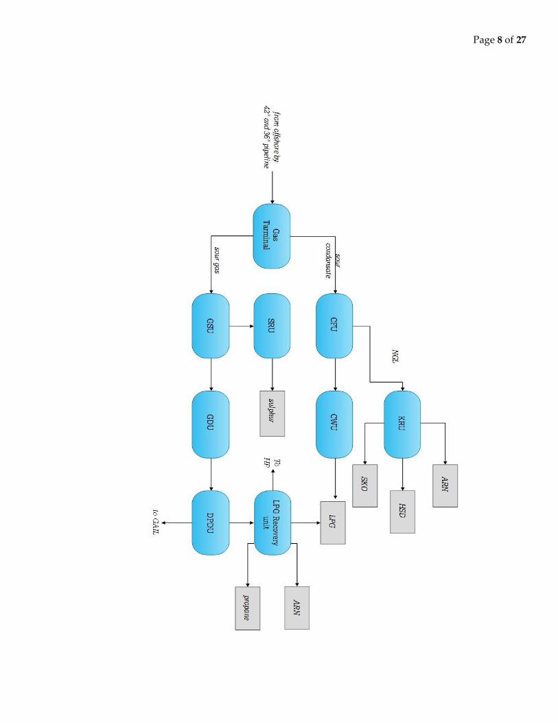
The sour gas and condensate are received from offshore in a multiphase flow.
They are separated by gravity into two steams, gas and liquid at initial stage. The sour gas
separated is taken out from top riser pipes of slug catcher to Gas Sweetening Unit (GSU) and
the sour liquid thus collected is routed to Condensate Fractionation Unit (CFU).
The purpose of GSU is to remove lethal H2S from sour gas. Sour gas from slug
catcher is distributed to different GSU trains, which comes in counter current contact with
lean amine solution (Methyl Di Ethanol Amine) in absorption column. The sweet gas leaves
from the top of the column with 4 ppm H2S which is routed to GDU/LPG units. The rich
amine enters the regeneration and re-circulation in the system. Acid gas liberated from top of
the regenerator column during recycling of amine forms feed for sulphur recovery unit.
The Gas Dehydration Unit (GDU) aims at removal of water vapors from
sweetened gas from GSU. The sweet gas in counter-current contact with lean Tri-Ethylene
Glycol (TEG) solution in absorption column. The dry gas liberated from top of the absorber
forms feed for Dew Point Depression Unit. The rich TEG is sent to reboiler to regenerator to
remove moisture. The regenerated TEG continuously recycled and reused in the system.
The purpose of DPD unit is to remove hydrocarbon condensate from the
sweetened and dehydrated gas by chilling to avoid hydrate formation in the long distance H-
B-J pipeline. The feed gas from GDU trains is chilled to about -5 0C in a chiller with the help
of propane refrigerator in closed circulation cycle. The cooled gas condensate is pumped to
LPG plant for distillation. The treated gas is then sent to GAIL for onward transmission to H-
B-J pipeline and partly to local consumers.
Page 6 of 27
The Condensate Fractionation Unit (CFU) aims at removal of H2S and recovery
of LPG and NGL (Natural Gas Liquid) from the sour hydrocarbon condensate separated in
the slug catcher. The liquid from slug catcher is distributed into stripper columns of various
CFU trains. H2S is stripper from the condensate along with lighter hydrocarbons and fed to
GSU trains for removal of H2S. The liquid from stripper bottom is fed to LPG column for
recovery of LPG from the top and NGL from the bottom. The LPG is sent to caustic wash
unit for removal of H2S. The LPG is sent to Caustic Wash Unit for removal of H2S. The NGL
forms the feed for KRU.
The LPG from CFU contains upto 20 ppm H2S which has to be removed to less
than the permissible limit of 4 ppm in CWU before it is sent for storage in Horton spheres.
The LPG is passed through absorber tower containing caustic solution to wash and remove
H2S.NGL produced from CFU is given value addition in KRU by way of producing aromatic
rich naptha (ARN), superior kerosene oil (SKO), heavy cut (HC) and/or high-speed diesel
(HSD). The hot NGL is fed to Naptha Column for distillation from where Naptha is
recovered as a top product. The bottom steam is fed to the kerosene column through the gas
fired furnace for further fractionation. Kerosene/ATF is recovered from top of the kerosene
column and HSD is recovered from the bottom.
A part of sweet gas from outlet of GSU (about 5 MMSCMD) and all the sweet
condensate from DPD are taken as feed to LPG recovery unit. Here cryogenic process is done
by turbo-Expander. The feed gas is first dried in molecular sieve dryers and then chilled in a
cold box to -300C. The chilled vapor is expanded isentropically in turbo-expander wherein
temperature of the gas falls to -570C. In the chilling process heavier hydrocarbons (C3+) get
liquefied and separated for fractionation in the LEF and LPG columns. The lean gas liberated
is further compressed as per requirement of consumer. The product come out from the LPG
unit is naphtha from bottom and LPG from top. A part of the LPG is further distillate to
obtain propane, which is used as a refrigeration cycle in LPG and DPD unit.
Page 7 of 27
The purpose of SRU is to convert acid gas liberated from GSU into elemental
sulphur for environment protection. Acid gas comes in contact with catalyst LOCAT solution
in absorber. H2S is oxidized to elemental sulphur in presence of the catalyst. Air is introduced
into Absorber for regeneration for catalyst. Sulphur is palletized up to 99% purity and sand
for disposal in HDPE bags in the market. The catalyst is re circulated in the system and make
up chemicals are dosed to maintain the quality. The vent gas from the top of absorber vessel
containing CO2, N2, O2 and moisture vented to atm.
Hazira plant also has utility units & offsite facilities for safe and smooth
operations. They are as follows,
1.) Cogeneration power
2.) Steam system
3.) Water system
4.) Air system
5.) Inert gas system
6.) Effluent treatment plant
7.) Product storage
8.) Dispatch
Page 8 of 27
Page 9 of 27
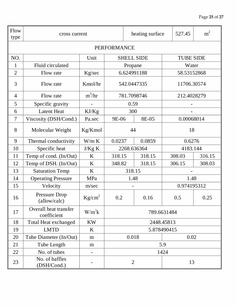
AIM:- Designing of de-superheating propane condenser for DPD unit from the
given data and compare the result with actual design.
DATA GIVE:-
Over all heat duty: - 2105798 Kcal/hr = 2448.458 KW
Hot fluid temperature, Inlet: - 75.67 0C
Outlet: - 45.00 0C
Cold fluid temperature, Inlet: - 43.00 0C
Outlet: - 33.00 0C
Operating Pressure: - 14.88 Kg/cm2
Baffles space: - 0.4 m
Outer diameter of tube: - 0.020 m
Inner diameter of tube: - 0.018 m
Length of tube: - 5.9 m
RESULT SHOULD BE MATCHED
WITH: -
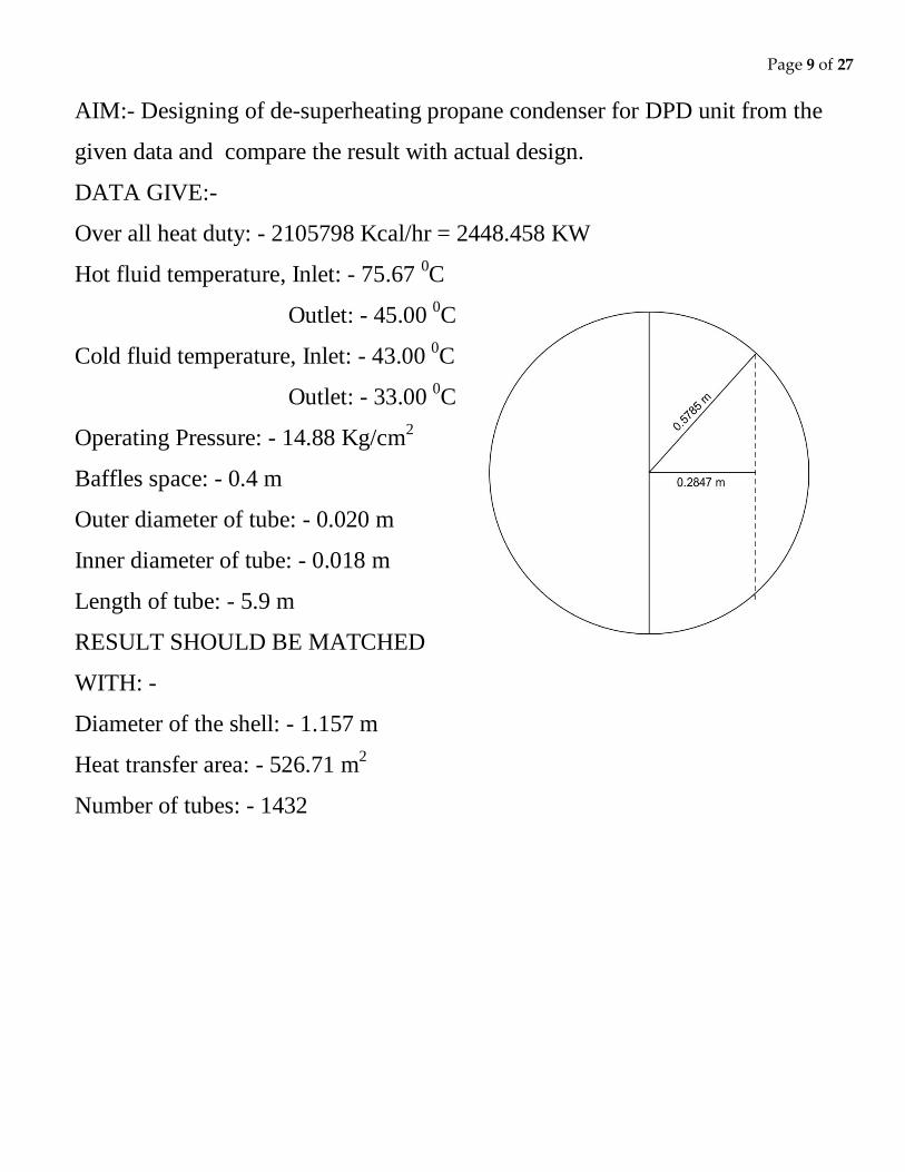
Diameter of the shell: - 1.157 m
Heat transfer area: - 526.71 m2
Number of tubes: - 1432
Page 10 of 27
SOLUTION: -
Now properties of water at average temperature T = 38 0C (311.5 K)
Density 992.0466 Kg/m3
Specific heat Cp 4183.144 J/Kg K
Viscosity 6.0814*10-4
Pa sec
Thermal conductivity k 0.6276 W/m K
Now for water,
Q = mCpt
Where,
Q = Total heat duty, KW = KJ/sec
m = mass flow rate of water, Kg/sec
t = Temperature gradient of water, K
Cp = specific heat of water, J/Kg K
K
KKgJ
J
tCp
Qm
10*.
144.4183
sec10*458.2448 3
= 58.53 Kg/sec
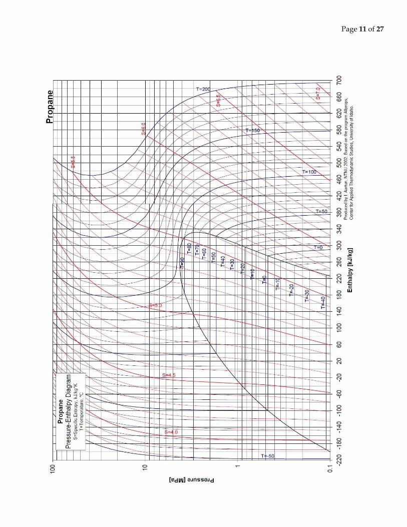
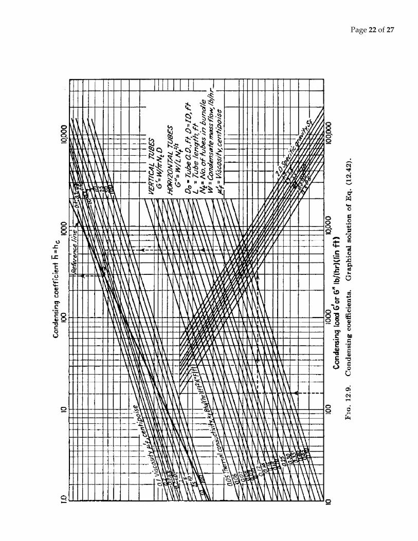
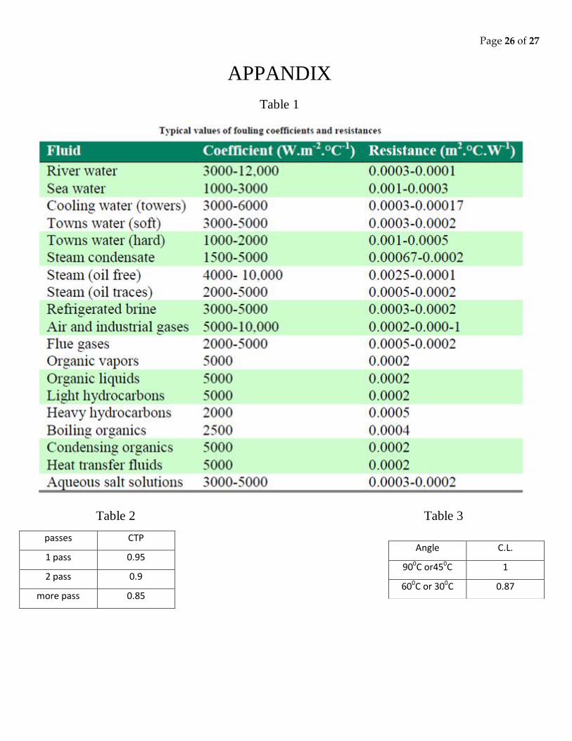
From P-H diagram (given on page no. 10) of propane at 1.46 MPa pressure,
Saturation temperature, Tset = 45 0C (318.15 K),
Specific heat, = 300 KJ/Kg.
Page 11 of 27
Page 12 of 27
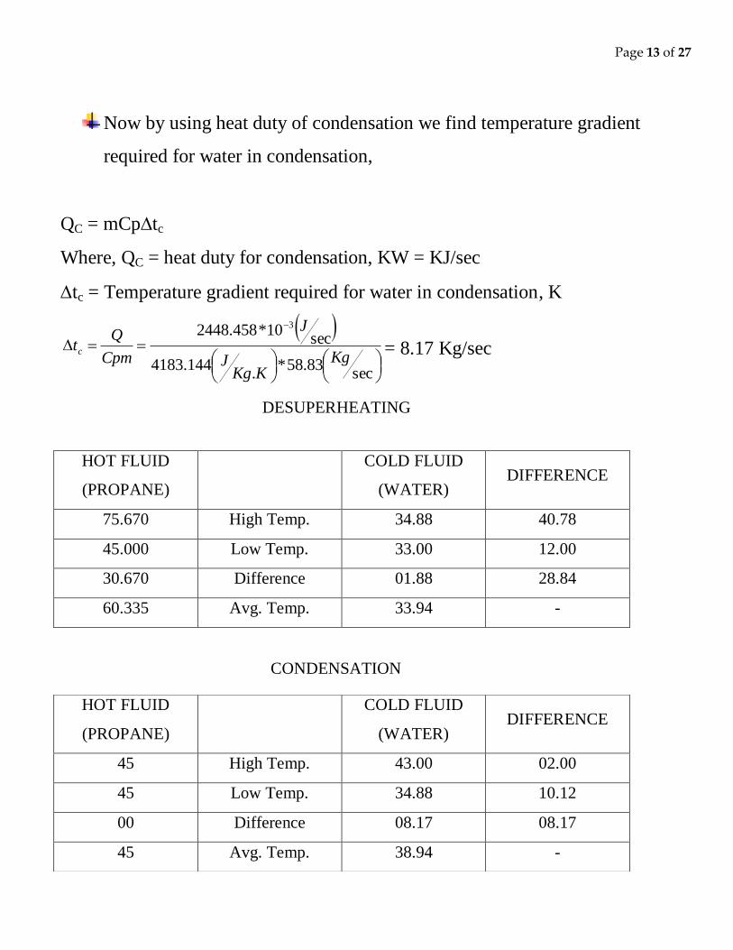
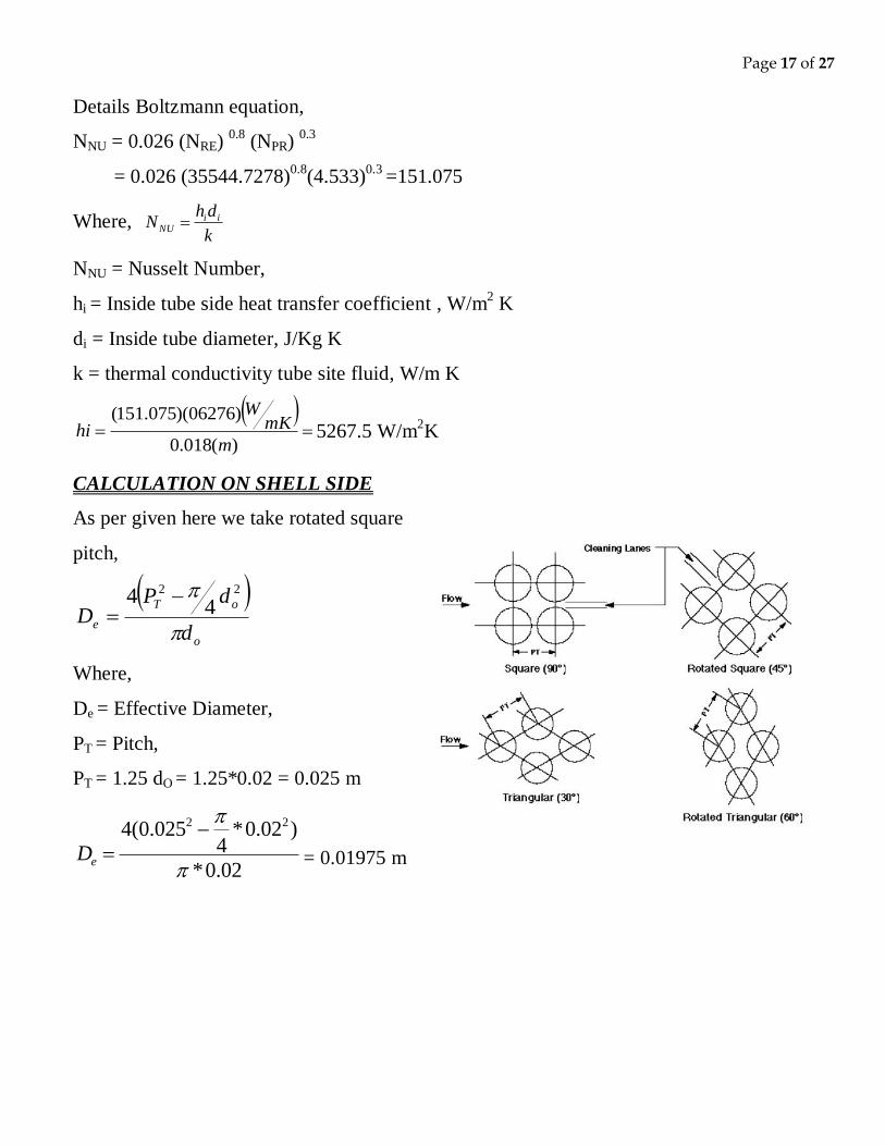
FOR DESUPERHEATING
Now properties of propane at average temperature of de-superheating T = 60 0C


![Oxygen Analyzer Jay Patel #19 April 27, 2011. Senior Design Project [1]](https://static.documents.pub/doc/80x56/5a4d1b0c7f8b9ab05998bd81/-oxygen-analyzer-jay-patel-19-april-27-2011-senior-design-project.jpg)


