Page 1
1
R.M.O.Pauletti - www.lmc.ep.usp.br/people/pauletti
Ruy Marcelo de Oliveira Pauletti
Polytechnic School of the University of São Paulo
Taut Structures
Taut Structures:
“those that require their elements to be taut,
instead of slack or wrinkled, to work properly.
Page 2
2
1
2
kf
m
A spring-mass system:
f nm
T
L
~g
Tk
L
A vibrating string:
Page 3
3
A transversaly loaded string:
2 2
4 14
rP u k uL u
r
EAk r
L
Non-linear equilibrium:
1
1
i
i i i
u
dgu u g u
du
Newton´s Method:
i
i
t
u
dgk
duTangent stiffness
Given F, find *
u such that F
u*
* *0g u P u F
0
0
4Tk
L
u
P
P=P(u)F
_
u*
_
u0
g0<0
g1
P1
kt0
1
Du1
u1=u0+Du1
g2
P2
kt1
1
Du2
u2=u1+Du2
g3
kt2
Du3
P3
u3=u2+Du3
Du4
1kT
3
P4
u4=u3+Du4
Newton´s Method for a scalar problem g=P(u)-F=0
1
1
i
i i t iu u k g u
1
Page 4
4
Geometrically Non-Linear Equilibrium, for many DOF:
*uFind such that * * *
g u = P u - F u 0
P = P u
F = F u
Internal Load Vector
External Load Vector
g = g u Unbalanced (‘Error’) Load Vector
Newton’s method:
-1
1
i
i i i
u
gu u g u
u
Tangent stiffness matrix
-1
i
i t i u K g u
i
i
t
u
gK
u
1 1 1
, 1, ,j i
i ij ijij ij
j i
n n n
j j j
N N i n
x xp p v
x x
1 1
2 2;
n n
f p
f pF P
f p
A System of Central Forces
Page 5
5
A System of Central Forces
P = C N
Vector of internal
element loads“Geometric operator”
( )
( )
( ) 1 ( ) )
3
(1
1 ( )
0 0 010 0
0 0
0 0 0 0
0
0 0 0
b be
e e e
n b
e
e b
i
j
n
v
v
C C
1
1b b
e
N
N
N
N
A System of Central Forces
P = C N
Vector of internal
element loads“Geometric operator”
T
t
N C FK CN F C N
u u u u
t c g ext K K K K
mu cu p u f t
f tA single DOF oscilator:
st
Fu
k
The Dynamic Relaxation Method
Page 6
6
A linear SDOF oscilator
under a step force:
0, 0
, 0
p u ku
tf t
F t
mu cu p u f t
f tA single DOF oscilator:
The Dynamic Relaxation Method
Kinetic Damping:
Transient of kinetic energy during the shape finding of a cable network via DR, with kinetic damping
The Dynamic Relaxation Method
“Peso portante << Peso portado”
( Majowiecki, 1994)Drawing by Enzo Pinto, Naples, 1985.
“Light structures”
Page 7
7
“Light structures”
Adapted from R. Serger, “Structures nouvelles in architecture”,
in Cahiers du centre d’estudes architecturales, n. 1, 1967, p. 42.
“Light structures, structures of light” – H. Berger
Page 8
8
King Fahd Stadium, Riyadh, Arábia Saudita (1986)
Page 11
11
R.M.O.Pauletti - www.lmc.ep.usp.br/people/pauletti
Page 13
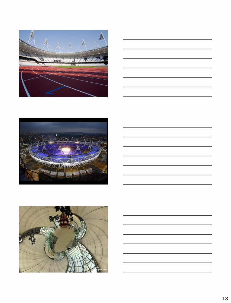
13
Photo by
Tim Nugent, 2009
Page 14
14
Suvarnabhumi Airport, Bangkok, Thailand
Page 16
16
(b) A ‘flexible’ structure, such as a cable, can change drastically its shape, when loading varies
Taut Structures are ‘flexible’:
(a) a stiff ‘structure’ , such as a bridge, does not change drastically its shape, when loading varies
Mardan, Paquistan, Aug, 2006
Earhquake in Eichuan, China (May, 2008)
Page 17
17
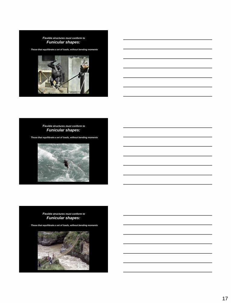
Flexible structures must conform to
Funicular shapes:
Those that equilibrate a set of loads, without bending moments
Flexible structures must conform to
Funicular shapes:
Those that equilibrate a set of loads, without bending moments
Flexible structures must conform to
Funicular shapes:
Those that equilibrate a set of loads, without bending moments
Page 18
18
Funicular Shapes:
The Catenaria
The Catenoid:
A family of conoids:
Page 19
19
The Helicatenoid
A gyroid (Alan Schoen, 1970)
A gyroid (Alan Schoen, 1970)
Page 20
20
A Schwarz-P surface
Costa’s Surface (1982):
Helaman Ferguson, 2008 AUSTRALIAN WILDLIFE HEALTH CENTRE
Helaman Ferguson, 1999
anticlastic
Double curvature superfaces
sinclastic
Single curvature
Page 21
21
A triangle immersed in a saddle-shape plane (a hyperbolic
paraboloid), as well as two diverging ultraparallel lines.
Equação de Laplace-Young
(equação das bolhas de sabão, ou das membranas):
Page 22
22
Uma estrutura ‘rígida’:
‘Stiff’ structures formal flexibility
‘Flexible’ structures formal stiffness
A paradox:
Planification
Single curvature surfaces can be
flattened without distortion;Double curvature surfaces undergoe distortion due to
flattening
Page 23
23
Winkel projection
Mercator projection
Mercator projection
Interrupted sinusoidal map
Mercator projection
Fueller´s Dymaxion Projection
Page 24
24
“No other class of architectural structural systems is as
dependent upon the use of digital computers as are tensile
membrane structures”.
David Campbel [ASCE Second Civil Engineering Automation Conference,
1991].
The Design Process of Taut Structures
DESIGN SOLUTION:
ARCHITECTURAL INTENTION:
PROJECT / ANALYSIS:
Final, viable shape
Initial, non-viable
shape
Patterning and
flattening:
Load analysis
Costa’s Surface:
Page 25
25
Costa’s Surface:
Symmetries & Patterns
Symmetries & Patterns
Costa’s Surface:
Realization: Lycra sculpture at EPUSP (2008)
Costa’s Surface:
Page 26
26
Igreja Batista Central
Fortaleza (2003)
Page 30
30
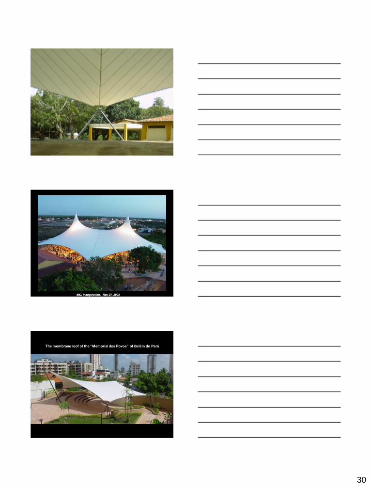
IBC, Inauguration , Nov 27, 2003
The membrane roof of the “Memorial dos Povos” of Belém do Pará
Page 31
31
S1 field, for prestressing loads S1 field, for a wind along the Y direction
displacement
norms, for a
wind along the
Y direction
geodesic patterns
non-geodesic patterns
Page 32
32
Cutting patterns
1st principal stresses
after flattening:
2nd principal stresses
after flattening:
1st principal stresses
before flattening:
2nd principal stresses
before flattening:1
Initial prestresses
Displacements due
to flattening:
Flattening process
Residual stresses
1st principal stresses after pull-back:2nd principal stresses after pull-back:
Stresses after pull-back
Maximum first principal stresses
after planification and pull-back
Maximum first principal stresses
for the prestress load case, as initially
calculated
Page 33
33
Maximum first principal stresses
after relaxation of pull-back stresses
Displacements due to relaxation of
pull-back stresses
Sliding Cables
Border cable
ridge cable
valley cable
“thalweg” cable
ideal-sliding model
Displacement
fields:
SI fields
SII fields
fully-adherent model
The Memorial dos Povos de Belém do Pará
Page 34
34
Pneumatic envelop for Angra 3
(September 2009)
Initial mesh modeled in SATS
equilibrium geometry under internal pressure
Page 36
36
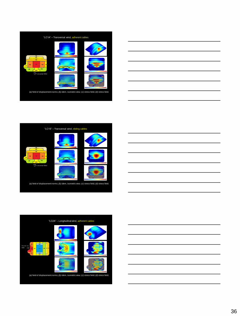
“LC1A” – Transversal wind, adherent cables
(a) field of displacement norms; (b) idem, isometric view; (c) stress field; (d) stress field.
“LC1S” – Transversal wind, sliding cables
(a) field of displacement norms; (b) idem, isometric view; (c) stress field; (d) stress field.
“LC2A” – Longitudinal wind, adherent cables
(a) field of displacement norms; (b) idem, isometric view; (c) stress field; (d) stress field.
Page 37
37
“LC2S” – Longitudinal wind, sliding cables
(a) field of displacement norms; (b) idem, isometric view; (c) stress field; (d) stress field.
R.M.O.Pauletti - www.lmc.ep.usp.br/people/pauletti
CENPES II – Rio de Janeiro, 2010Archs. Ziegbert Zenettini, Wagner Garcia
CENPES II - Petrobrás Research Center
Page 38
38
R.M.O.Pauletti - www.lmc.ep.usp.br/people/pauletti
R.M.O.Pauletti - www.lmc.ep.usp.br/people/pauletti
R.M.O.Pauletti - www.lmc.ep.usp.br/people/pauletti
Page 39
39
R.M.O.Pauletti - www.lmc.ep.usp.br/people/pauletti
Tensoestruturas