GIF/PRPPWG/2011/002 Proliferation Resistance and Physical Protection of the Six Generation IV Nuclear Energy Systems July 15, 2011 Prepared Jointly by: The Proliferation Resistance and Physical Protection Evaluation Methodology Working Group and the System Steering Committees of the Generation IV International Forum
Transcript
GIF/PRPPWG/2011/002
Proliferation Resistance and Physical Protection of the Six Generation IV Nuclear Energy Systems
July 15, 2011
Prepared Jointly by:
The Proliferation Resistance and Physical Protection
Evaluation Methodology Working Group and the
System Steering Committees of the Generation IV International Forum
ii
(This page has been intentionally left blank.)
iii
CONTENTS
ACRONYMS AND ABBREVIATIONS .......................................................................................................... vii
4.2 Next Steps .................................................................................................................................. 18
APPENDIX A ............................................................................................................................................... 20
PART II System White Papers .................................................................................................................. 27
Very High-Temperature Reactor (VHTR) .................................................................................................... 29
1. Overview of Technology ............................................................................................................. 29
2. Overview of Fuel Cycle(s) ........................................................................................................... 34
3. PR&PP Relevant System Elements and Potential Adversary Targets ....................................... 35
4. Proliferation Resistance Considerations Incorporated into Design ............................................ 37
5. Physical Protection Considerations Incorporated into Design .................................................... 38
6. PR&PP Issues, Concerns and Benefits ...................................................................................... 39
1 Overview of Generation IV Systems ...................................................................................... 6
A.1 Summary of PR&PP Characteristics of the GIF Design Concepts........................................ 20
SFR.1 Key Design Parameters of Generation IV SFR Concepts ..................................................... 50
GFR.1 Exploratory Phase Design Results for the Four Combinations of Options Used for Fuel Selection ......................................................................................................... 72
GFR.2 Fuel Composition for a Ceramic GFR Core........................................................................... 75
LFR.1 Main Characteristics of the SSTAR and ELSY ...................................................................... 85
LFR.A.1 Design Provisions Proposed for ELSY .................................................................................. 96
MSR.1 Uranium Isotopes Inventories at Equilibrium ......................................................................... 110
FIGURES
VHTR.1 Illustration of Coated Particle Fuel in the Prismatic Fuel Element ....................................... 30 VHTR.2 GT-MHR Reactor, Cross-Duct and PCU Vessels ............................................................... 31 VHTR.3 GT-MHR Fully-Embedded Reactor Building ........................................................................ 31 VHTR.4 Illustration of Coated Particle Fuel in Pebble Fuel Element ................................................ 32 VHTR.5 400 MW-thermal PBMR Partially Embedded Reactor Building with
Reactor Vessel and Turbine Lay-down................................................................................ 33 VHTR.6 250 MW-thermal HTR-PM Reactor Building Elevated above Ground
Level with Steam Generator; Spent Fuel Storage Not Shown ............................................ 33 VHTR.7 Diagram of VHTR Nuclear System Elements ...................................................................... 35 SFR.1 Japan Sodium-cooled Fast Reactor .................................................................................... 46 SFR.2 KALIMER-600 System Configuration .................................................................................. 47 SFR.3 Elevation View of SMFR System ......................................................................................... 49 SFR.4 SFR System Elements Containing Nuclear Material ........................................................... 53 SCWR.1 SCWR Concept .................................................................................................................... 59 SCWR.2 Reactor and Turbine Building of the High Performance Light Water Reactor ..................... 60 SCWR.3 Concept of the Super Fast Reactor ..................................................................................... 61 SCWR.4 Conceptual Pressure-Tube Type SCWR Layout and Thermal Cycle ................................. 62 SCWR.5 PR&PP Relevant System Elements of Pressure-Tube-Type SCWR .................................. 64
vi
GFR.1 Schematic Views of the GFR Reference Design ................................................................. 69 GFR.2 Indirect Combined Gas/Steam Power Conversion System ................................................. 70 GFR.3 Overview of the Secondary and Emergency Systems Connected to the
Primary Circuit through the Spherical guard vessel ............................................................ 71 GFR.4 a) Pin Type Fuel Element and b) Honeycomb Plate Type Fuel Element ............................ 72 GFR.5 Simplified Chart for Carbide or Nitride Fuel Fabrication ...................................................... 74 GFR.6 General Design of a GFR Plant Layout ............................................................................... 76 GFR.7 Schematic Representation of the Emergency Cooling System ........................................... 78
LFR.1 Primary System Configuration of ELSY ............................................................................... 83 LFR.2 The Small Secure Transportable Autonomous Reactor ...................................................... 85 LFR.3 Conceptual Development Schedule of the LFR .................................................................. 87 LFR.4 ELSY Plot Plan .................................................................................................................... 89 LFR.A.1 SSTAR with All Fuel Pins Shown ........................................................................................ 96 LFR.A.2 ELSY Core Configuration .................................................................................................... 97 LFR.A.3 FA Cross Section at Level of the Fuel Pins.......................................................................... 98 LFR.A.4 ELSY Reactor Building ........................................................................................................ 99 LFR.A.5 ELSY General Layout (3D) .................................................................................................. 99 MSR.1 Schematic View of a Quarter of the MSFR. ......................................................................... 104 MSR.2 Overall Scheme of the Fuel Salt Management Including the Online Gaseous
Extraction and the Off-line Reprocessing Unit .................................................................... 106 MSR.3 Diagram of MSFR Nuclear System Elements...................................................................... 107 MSR.4 Heavy Element Inventory for the
233U-Started MSFR and for the
Transuranic-Started MSFR .................................................................................................. 110 MSR.5 Evolution of the
232U/U ratio in the core and in the fertile blanket during
reactor operation for both U-started MSFR and TRU-started MSFR .................................. 111 MSR.6 Decay Scheme of
VNIINM A.A. Bochvar All-Russian Scientific Research Institute for Inorganic Materials
x
xi
(This page has been intentionally left blank.)
1
ABSTRACT This report presents the status of proliferation resistance and physical protection (PR&PP) characteristics for each of the six nuclear energy systems selected by the Generation IV International Forum (GIF) for further research and development. The intent is to generate preliminary information about the PR&PP merits of each system and to recommend directions for optimizing their PR&PP performance. The PR&PP Methodology, developed by the GIF Proliferation Resistance and Physical Protection Working Group (PRPPWG), provides a comprehensive framework and guidance for carrying out a system evaluation. This report was prepared jointly by the PRPPWG and the six GIF System Steering Committees (SSCs), and it is an outcome of workshop exchanges and white paper collaborations for each of the GIF system designs. For each design concept, the report catalogues the proliferation resistance aspects in terms of robustness against State-based threats associated with diversion of materials, misuse of facilities, breakout scenarios, and production in clandestine facilities. Similarly, for physical protection, this report catalogues the robustness against theft of material and sabotage by non-State actors. The report captures the current salient features of the GIF system design concepts that impact their PR&PP performance. It identifies crosscutting studies to assess PR&PP design or operating features common to various GIF systems. In addition, it suggests beneficial characteristics of the design of future nuclear energy systems, beyond the nuclear island and power conversion system, that should be addressed in subsequent GIF activities.
2
(This page has been intentionally left blank.)
1
EXECUTIVE SUMMARY The Generation IV International Forum has stated four goals to assess performances of GIF nuclear energy systems: proliferation resistance and physical protection; sustainability; economics; and safety and reliability. Methodologies have been developed for evaluating Generation IV systems against these criteria. With regard to PR&PP performance, the PR&PP methodology developed by the PRPPWG provides a comprehensive framework and guidance for carrying out a system evaluation. However, when undertaking a specific case study, difficulties arise from either the lack of specific information in the early stages of design or the proprietary nature of detailed information for mature designs. In order to facilitate the timely introduction of PR&PP characteristic into the design process, an effort was initiated in 2007 between the GIF SSCs and the PRPPWG to move forward in this area. This report, prepared jointly by the PRPPWG and the six SSCs, presents the status of PR&PP characteristics for each of the six systems selected by GIF for further research and development. The intent is to generate preliminary information about the PR&PP merits of each system and to recommend directions for optimizing their PR&PP performance. The three main objectives of this work are to: capture the current salient features of the design concepts that impact their PR&PP performance; identify crosscutting studies that assess PR&PP design or operating features common to various GIF systems; and suggest beneficial characteristics of the design of future nuclear energy systems, beyond the nuclear island and power conversion system, that should be addressed in subsequent GIF activities. Accordingly, white papers have been developed jointly by the SSCs and the PRPPWG for each of the GIF designs to identify qualitative design features that condition proliferation resistance (fuel cycle technologies, nature and throughput of nuclear materials in the fuel cycle, and achievable surveillance) and physical protection (nature of active or passive safety features, details on the confinement/containment of radioactive materials, and possible collocation with spent fuel processing plants). These are presented as Section II of the present report. Results and recommendations of generic interest on PR&PP features that may be derived from initial generic studies are expected to yield valuable guidelines for proceeding with further detailed conceptual studies of GIF systems. Further, desirable features for the global architecture of future nuclear plants to minimize risks of proliferation and optimize physical protection constitute another type of generic study that may lead to recommendations on the layout of fresh and spent fuel storage areas, on handling nuclear materials on the site, on hardening parts of nuclear service buildings, and on implementing dedicated instrumentation to achieve an effective surveillance of nuclear materials and/or sensitive subsystems. The PRPPWG interacts with the SSCs in order to conduct generic studies on the GIF systems and to oversee evaluations made by the SSCs of their specific system for the sake of consistency across all GIF systems. This approach leaves to the SSCs the ultimate responsibility of the final assessment of PR&PP features of their respective designs, with input from the PR&PP subject matter experts. The focus of the GIF designs as coordinated by the SSCs is primarily on the reactor with rather less emphasis on the fuel cycle that the reactor is imbedded within. The current report reflects on the broader fuel cycle context and discusses some crosscutting concepts with regard to fuel cycle. Other areas in which there is likely to be crosscutting topics are: fuel type, coolant, moderator, refuelling modes, and safeguards. To varying degrees there are commonalities among the GIF designs but there are also distinctions. These are discussed in Section I of the report. The major crosscuts of safety and economics are also discussed in terms of their current state of development for evaluation of GIF systems. The linkage of these efforts to PR&PP is also discussed in this report. Each white paper that is presented in Section II of this report is a stand-alone statement on the state-of-the-art with regard to PR&PP for each nuclear energy system. As can be seen from each report, the level of development varies among the design concepts. This is to be expected since some design concepts have historically and collectively been given more attention than others. It is not the purpose of this report
2
to perform a differential evaluation of the designs for comparative assessments. Rather, we seek to define paths forward for each design, taken on its current status, for research and development to enhance PR&PP characteristics. For each design concept, this report catalogues the proliferation resistance aspects in terms of robustness against State-based threats associated with diversion of materials, misuse of facilities, breakout scenarios, and production in clandestine facilities. Similarly, for physical protection, this report catalogues the robustness against theft of material and sabotage by non-State actors.
PART I General Overview
3
PART I
General Overview
PART I General Overview
4
(This page has been intentionally left blank.)
PART I General Overview
5
1 Introduction 1.1 Objectives In the framework of the Generation IV International Forum, proliferation resistance and physical protection, together with sustainability, economics, and safety and reliability are goals to assess the performance of Generation IV systems. Refined methodologies have been developed for evaluating Generation IV systems against these criteria. With regard to PR&PP performance, the PR&PP Methodology developed by the PRPPWG provides a comprehensive framework and guidance for carrying out a system evaluation. However, when undertaking a specific case study, difficulties arise from either the lack of specific information in the early stages of design or the proprietary nature of detailed information for mature designs. This report, prepared jointly by the PRPPWG and the six SSCs, presents the status of PR&PP characteristics for each of the six systems selected by GIF for further research and development. The intent is to generate preliminary information about the PR&PP merits of each system and to recommend directions for optimizing its PR&PP performance. The three main objectives of this work, identified during the first workshop which brought together SSC representatives and PRPPWG member, are: capturing in the short-term salient features of the design concepts that impact their PR&PP performance; identifying crosscutting studies that assess PR&PP design or operating features common to various GIF systems; and suggesting beneficial characteristics of the design of future nuclear power plants, beyond the nuclear island and power conversion system, that should be addressed in subsequent GIF activities. Firstly, white papers have been developed by the SSCs to identify qualitative design features that condition proliferation resistance (fuel cycle technologies, nature and throughput of nuclear materials in the fuel cycle, and achievable surveillance) and physical protection (nature of active or passive safety features, details on the confinement/containment of radioactive materials, and possible collocation with spent fuel processing plants). Secondly, results and recommendations of generic interest on PR&PP features may be derived from the application of the evaluation methodology to a set of GIF systems. Specific recommendations that may be derived from such generic studies are expected to yield valuable guidelines for proceeding with further detailed conceptual studies of GIF systems. Thirdly, desirable features for the global architecture of future nuclear plants to minimize risks of proliferation and optimize physical protection constitute another type of generic study that may lead to recommendations on the layout of fresh and spent fuel storage areas, on handling nuclear materials on the site, on hardening parts of nuclear service buildings, and on implementing dedicated instrumentation to achieve an effective monitoring and surveillance of nuclear materials and/or sensitive subsystems. An action plan that builds on the current PR&PP evaluation methodology and its application to the case study of an example sodium fast reactor, and that makes use of the three types of above-suggested studies, is being currently followed in GIF. This leads the PRPPWG to interact with SSCs in order to conduct generic studies on the GIF systems, and to oversee evaluations made by the SSCs of their specific system for the sake of consistency across all GIF systems. This approach leaves to the SSCs the ultimate responsibility of the final assessment of PR&PP features of their respective designs, with input from the PR&PP subject matter experts.
PART I General Overview
6
1.2 Scope The main characteristics of the six GIF systems are summarized in Table 1 and a brief overview of the design concepts under consideration within the six SSCs is given below (GIF 2009 Annual Report, http://www.gen-4.org/PDFs/GIF-2009-Annual-Report.pdf).
fast sodium 500-550 On-Site; Offline batch / Offline full core (Off-site)
closed 50-150 300-1 500 600-1 500
SCWR (supercritical water-cooled reactor)
thermal/ fast
water 510-625 On-site; Offline batch / Online continuous
open/closed
300-700 1 000-1 500
GFR (gas-cooled fast reactor)
fast helium 850 On-site; Offline batch
closed 1 200
LFR (lead-cooled fast reactor)
fast lead 480-570 On-site; Offline batch / Offline full core (Offsite)
closed 10-100 300-1 200 600-1 000
MSR (molten salt reactor)
thermal/ fast
fluoride salts
700-800 On-site; Online continuous
closed 1 000
VHTR – The very-high-temperature reactor is a further step in the evolutionary development of high-temperature reactors. The VHTR is a helium-gas-cooled, graphite-moderated, thermal neutron spectrum reactor with a core outlet temperature higher than 900°C, and a goal of 1 000°C, sufficient to support high temperature processes such as production of hydrogen by thermo-chemical processes. The reference thermal power of the reactor is set at a level that allows passive decay heat removal, currently estimated to be about 600 MWth. The VHTR is useful for the cogeneration of electricity and hydrogen, as well as to other process heat applications. It is able to produce hydrogen from water by using thermo-chemical, electro-chemical or hybrid processes with reduced emission of CO2 gases. At first, a once-through low enriched uranium (<20%
235U) fuel cycle will be adopted, but a closed fuel cycle will be assessed, as well
as potential symbiotic fuel cycles with other types of reactors (especially light-water reactors) for waste reduction purposes. The system is expected to be available for commercial deployment by 2020.Some examples of major VHTR design options that potentially affect PR&PP are:
Prismatic versus pebble fuel
Type of fresh fuel [low enriched uranium (LEU), Pu, transuranics (TRU), 233
SFR – The sodium-cooled fast reactor system uses liquid sodium as the reactor coolant, allowing high power density with low coolant volume fraction. It features a closed fuel cycle for fuel breeding and/or actinide management. The reactor may be arranged in a pool layout or a compact loop layout. The reactor-size options which are under consideration range from small (50 to 150 MWe) modular reactors to larger reactors (300 to 1 500 MWe). The two primary fuel recycle technology options are advanced aqueous and pyrometallurgical processing. A variety of fuel options are being considered for the SFR, with mixed oxide preferred for advanced aqueous recycle and mixed metal alloy preferred for pyrometallurgical processing. Owing to the significant past experience accumulated with sodium cooled reactors in several countries, the deployment of SFR systems is targeted for 2020. Some examples of major SFR design options that have PR&PP implications are:
Transmuter versus converter versus breeder (net consumption/production of fissile material)
Homogeneous versus heterogeneous recycle scheme [minor actinide (MA) loading]
Existence versus absence of blanket elements
Multi-batch versus cartridge refuelling scheme SCWR – Supercritical water-cooled reactors are a class of high-temperature, high-pressure water-cooled reactors operating with a direct energy conversion cycle and above the thermodynamic critical point of water (374°C, 22.1 MPa). The higher thermodynamic efficiency and plant simplification opportunities afforded by a high-temperature, single-phase coolant translate into improved economics. A wide variety of options are currently considered: both thermal-neutron and fast-neutron spectra are envisaged; and both pressure vessel and pressure tube configurations are considered. The operation of a 30 to 150 MWe technology demonstration reactor is targeted for 2022. Some examples of SCWR major design options that have PR&PP implications are:
Pressure vessel versus pressure tube (off-load versus on-load refuelling)
Fuel cycle scheme [once-through (LEU) versus recycle (U/Pu or Th/U mixed oxides)] GFR – The gas-cooled fast reactor combines the advantages of a fast neutron core and helium coolant giving possible access to high temperatures. It requires the development of robust refractory fuel elements and appropriate safety architecture. The use of dense fuel such as carbide or nitride provides good performance regarding plutonium breeding and minor actinide burning. A technology demonstration reactor needed for qualifying key technologies could be in operation by 2020. Some examples of GFR design variations that have PR&PP implications are:
Breeding gain
Pu isotopics (reactor-grade versus deep-burn grade)
Use of MA loaded fertile blankets LFR – The lead-cooled fast reactor system is characterized by a fast-neutron spectrum and a closed fuel cycle with full actinide recycling, possibly in central or regional fuel cycle facilities. The coolant may be either lead or lead/bismuth eutectic. The LFR may be operated as: a breeder; a burner of actinides from spent fuel, using inert matrix fuel; or a burner/breeder using thorium matrices. Two reactor size options are considered: a small 10-100 MWe transportable system with a very long core life and a medium 600 MWe system. In the long term a large system of 1200 MWe may be envisaged. The LFR system may be deployable by 2025.The modular transportable design option differs from the medium system by having a life time core that does not require onsite refuelling. As such there is no fresh or spent fuel inventory at the plant site for the modular design. MSR – The molten-salt reactor system embodies the very special feature of a liquid fuel. MSR concepts, which may be used as efficient burners of transuranic elements from spent light-water reactor (LWR) fuel, also have a breeding capability in any kind of neutron spectrum ranging from thermal (with a thorium fuel cycle) to fast (with a uranium-plutonium fuel cycle). Whether configured for burning or breeding, MSRs have considerable promise for the minimization of radiotoxic nuclear waste. (The MSR white paper only
PART I General Overview
8
covered the fast breeder option operated with liquid fuel in the thorium fuel cycle.) Some examples of MSR design options that have PR&PP implications are:
Breeder versus burner;
Use of fertile radial blanket;
Fresh fuel inventory outside the core; and
233
U versus Pu (TRU) initial core. 2. How the Report Was Prepared 2.1 Workshops In 2007 discussions began between the PRPPWG and representatives of the SSCs for each of the six GIF systems on ways and means to cooperate aiming at pursuing joint projects. A first workshop was held in May 2008 at Brookhaven National Laboratory (BNL, United States), where representatives from the SSCs met with members of the PRPPWG. The discussions carried out during the workshop highlighted the need to exchange information and work together in order to promote a better understanding within SSCs of PR&PP issues and to enhance the user friendliness of the PR&PP Methodology. It was decided then to undertake the drafting of System White Papers focusing on PR&PP issues for each of the six systems. The main outcome of the workshop was a program plan for future joint activities. Three broad goals were defined for those activities: capture in the near term salient features of the design concepts that impact their PR&PP performance; conduct crosscutting studies that assess PR&PP measures against design or operating features common to various GIF systems; and derive functional requirements for the design and the global layout of future nuclear energy systems. A follow-on workshop was held in July 2009, also at BNL, during which the SWPs were discussed and further advanced. A third workshop was held in Bologna, Italy, in January 2010 to finalize the structure and content of the System White Papers. At that stage, it was decided to undertake jointly the preparation of a compendium document incorporating the six System White Papers and sections on cross-cutting issues. It was agreed that the report would be submitted to the GIF Experts Group for final review and could be issued eventually to the GIF community and beyond upon receiving clearance from the GIF Policy Group. 2.2 Production of White Papers The PRPPWG developed a template providing a framework covering structure and desirable content of the System White Papers. The SSCs prepared successive drafts of the System White Papers providing key design information on their respective systems relevant from the PR&PP viewpoint. The drafts were reviewed by members of the PRPPWG who provided comments and suggestions on enhancing their comprehensiveness and harmonizing their level of detail and coverage, in so far as feasible. After several iterations, the System White Papers were cleared by SSCs for further use within GIF and in particular for contributing to the compendium document. The exchange of information and technical discussions associated with the preparation of the SWPs, including the successive iterations, were beneficial for both the PRPPWG and the SSCs. The SSCs acquired a better understanding of the ways and means to apply the PR&PP Methodology and of the benefits of results from its application for enhancing PR&PP performance of their designs. The PRPPWG acquired a better appreciation of the users‟ requirements and received valuable guidance on improvements that could be implemented in the proposed methodological approach.
PART I General Overview
9
2.3 Drafting of the Report The PRPPWG took the lead responsibility for drafting the present report. It designed the structure and table of contents and compiled the information provided by SSCs together with other relevant materials. The draft was reviewed by SSCs, which provided consistent checking on technical information. 3. Cross-cutting Topics Several topical areas have cross cutting studies:
Fuel type,
Coolant, moderator,
Refueling modes,
Fuel cycle architecture,
Safeguards, and
Other GIF topics (safety and economics). The following sections provide an overview of each study and mentions characteristics of PR&PP interest. 3.1 Fuel Type Fuel type refers to the physical form, chemical form and isotopic composition of the fissile component of a nuclear reactor. The fuel for the six GEN IV designs takes the form of:
Assembly with fuel rods [SFR, SCWR, LFR, GFR (pins or plates)]
Prismatic-block with coolant channels (VHTR)
Pebble (VHTR)
Molten salt (MSR) The physical form has relevance to PR&PP with regard to the weight, bulk, and configuration of the fuel. Weight and bulk are two of the basic attributes for PR&PP evaluations. The bulk of the fuel form also determines the safeguards approach for material accountancy [item (assembly and block) versus bulk (pebble and liquid salt)]. The configuration of the fuel has direct implications for identifying potential proliferation pathways, e.g., pin diversion and clandestine production (reconstitute fuel with fertile material). The isotopic composition of the fuel can be categorized according to the phase in its life cycle, i.e., fresh, core, and spent fuel. One of the common metrics for describing the attractiveness of fuel is its fissile isotope content. The materials of interest to PR&PP in fresh fuel are the fissile isotopes of uranium and all isotopes of plutonium. For LEU the
235U enrichment is a parameter of interest while for MOX it is the
enrichment in Pu. In a thorium cycle fuel the presence of 238
U can make the separation of 233
U more difficult. The composition of core and spent fuel is a function of its utilization in the reactor and the time since its discharge. For core fuel and spent fuel the special nuclear materials of interest in the context of PR&PP are the TRU (Pu in particular),
233U/
232U (Th cycle), and the MA (for the transmuter mode).
Radiotoxicity, heat load, and spontaneous fission are some of the other fuel properties related to the isotopic composition. These properties are often associated with the material type attributes of PR&PP target materials.
PART I General Overview
10
Chemical composition of the fuel includes the material of the fuel compact and the engineered barriers (e.g., clad of fuel pins). Typical compositions of fuel compact are:
Oxide (e.g., UO2, MOX, ThO2)
Nitride or carbide [e.g., (U,TRU)N and (U,TRU)C]
Metal (e.g., U-TRU-10%Zr alloy)
Salt [e.g., 7Li-ThF4-(TRU or
233U)F3]
Typical clad materials are:
Metal (e.g., zircaloy, ODS, HT9, T91, 316-SS)
Ceramic (e.g., SiC, ZrC)
Pyrolytic carbon (as in TRISO coated fuel particle) The chemical composition of fuel compact and the clad material both have implications in the choice of technology and the ease of separation and reprocessing of fuel. For example the reprocessing of TRISO fuel particle would require first the separation of the pyrolytic carbon from the ceramic fuel kernel. The three solid-fuel fast neutron reactors (GFR, LFR, and SFR) allow for, but do not require, the use of blanket assemblies where
239Pu can be produced.
3.2 Coolant, Moderator Moderator is only present in thermal reactors. Among the reactors described in the white papers only the VHTR and one of the design options of the SCWR are thermal reactors
1. In the case of the VHTR the
slowing down of neutrons occur in the carbon matrix of the fuel compact (TRISO particles embedded in pebble or prismatic block). For the SCWR either light water (the pressure vessel option) or heavy water (the pressure tube option) is the moderator. The coolant environment affects safeguards systems. With the exception of the SCWR all other reactors described in the white papers rely on non-aqueous coolants:
Helium gas for the GFR and the VHTR.
Liquid metal for the SFR and the LFR.
Liquid salt for the MSR. Liquid metal prevents verification of core fuel by direct visual inspection because the coolant is opaque, and this affects safeguards operation. Liquid salt is the opaque coolant and the carrier of the MSR fuel, and the safeguards inspection of the MSR fuel is performed by sampling only. It is impossible to tag the MSR fuel by serial number. A common feature shared by the LFR and the MSR is the solidification of the coolant when the reactor is shut down. For the SFR, heating is provided to prevent sodium solidification upon shutdown. 3.3 Refueling Modes Refueling is either performed offline with the reactor shut down (in periodic batches or full-core cassette replacement) or online continuously while the reactor is operating. The frequency and mode of refueling have relevance to PR&PP with respect to accessibility of the fuel before, during, and after the refueling process, and the potential misuse of the refueling process to produce and divert weapons-usable material.
1 A thermal option is under consideration for the MSR, but the MSR white paper covers only the fast breeder option
operated with liquid fuel in the thorium fuel cycle.
PART I General Overview
11
Five of the six GIF systems have variations that are refueled offline in batches:
the prismatic-block core VHTR;
medium and large, pool or loop type SFRs;
the pressure vessel design option of the SCWR;
medium and large pool-type LFRs; and
GFR. All of these systems share aspects of on-site solid fuel management: new fuel acceptance, spent fuel handling, and out-of-reactor storage. Two GIF systems have a design variation that is refueled by a full-core replacement:
the small, sealed, transportable, autonomous reactor (SSTAR) variation of the LFR; and
the small modular pool-type SFR (SMFR). In SSTAR the compact active core is removed as a single cassette during refueling and replaced by a fresh core. Fresh or spent fuel storage is not envisioned as part of the normal operations, and full cassette core replacement would take place only at end of core life (15-30 years) and would be carried out by the reactor supplier. Similarly, a key design feature of the SMFR is the long-lived core – 30 years with no refueling. Both of these systems eliminate all aspects of on-site fuel management – new fuel acceptance, spent fuel handling, and out-of-reactor storage – a characteristic which is beneficial from the PR&PP viewpoint. Three GIF systems have variations that are refueled continuously online:
the pebble-bed version of the VHTR;
pressure tube design options for the SCWR; and
the MSR. The pebble-bed VHTR and pressure tube SCWRs share aspects of on-site solid fuel management while also using an online automated refueling process. In the liquid-fueled MSR, however, refueling and liquid fuel processing are integrated. A small side stream of the molten salt is processed for fission product removal and then returned to the reactor. Thorium is the main component, which has to be added during reactor operation in the form of thorium fluoride. The constraints on the storage of thorium are that of fertile materials. If the choice of a fertile blanket is made in the design, excess uranium management and storage will be necessary to store the uranium produced in excess of the fissile needs of the reactor. MSRs do not have spent nuclear fuel, except the fuel salt when the reactor is decommissioned. 3.4 Fuel Cycle Architectures Three of the six GIF systems are strictly fast neutron reactors (SFR, GFR, and LFR); two others can be built as fast reactors (MSR and SCWR); and only two operate with slow neutrons (VHTR and SCWR). Four of the six GIF systems (SFR, GFR, LFR, and MSR) employ only a closed fuel cycle, as do the fast spectrum design variations of the SCWR. The thermal spectrum SCWRs and the VHTR designs employ a once-through open fuel cycle, and share the fuel cycle characteristics of today‟s nuclear reactor systems: mining and milling, conversion, fuel enrichment, fuel fabrication, fresh fuel transport and on-site storage, spent fuel storage, transport, and disposal. All solid fueled GIF systems are likely to rely on off-site fuel fabrication plants for fresh fuel supply. A fuel cycle phase common to all solid fueled closed fuel cycle systems is transportation of the spent fuel to the separations facility. Transportation requirements will depend heavily on the fuel cycle technology configuration (co-located or centralized). Most of the solid fueled closed fuel cycle GIF systems will likely transfer spent fuel to small regional or large centralized reprocessing facilities. However, some system
PART I General Overview
12
design variations may allow for on-site spent fuel reprocessing and fresh fuel fabrication (e.g., metal-fueled SFR with co-located pyrometallurgical reprocessing). The thermal option SCWRs with UO2 as fuel will use a conventional once-through fuel cycle with fuel enrichment of up to 6% and an exit burnup of up to 60 GWd/tHM. It will require LEU fuel enrichment and fuel fabrication facilities for fuel supply. There are a number of possible thermal SCWRs with once-through fuel cycles that employ thorium. Since thorium is fertile, not fissile, a fissile material is needed to start the process. This fissile isotope is typically
235U,
233U (which is bred from an earlier thorium cycle), or
239Pu. The thorium fuel cycles are being considered for the pressure-tube SCWR design with a heavy-
water moderator and light water coolant. The thorium direct-self-recycle option of the SCWR is a near-term means of exploiting thorium, without investing in expensive recycle technologies. In contrast, the fast option SCWR with MOX fuel uses a conventional U-Pu fuel cycle, and would likely rely on an off-site fuel fabrication plant and an off-site (regional or centralized) facility with full actinide recycle based on conventional reprocessing. Base-line designs of the three solid-fueled fast neutron reactors (GFR, LFR, and SFR) are not conventional fast breeders, i.e., they do not have a blanket assembly where
239Pu is produced. Instead,
plutonium production takes place in the core, where burnup is high and the proportion of plutonium isotopes other than
239Pu remains high. However, some design options of the GFR and SFR include
blankets. The primary SFR, LFR, and GFR variants that are considered in this report all utilize depleted uranium as the fuel matrix:
a 50 MWe pool-type SFR with a long-lived single cartridge refueling strategy eliminating all aspects of on-site fuel management, and using U-TRU metal fuel requiring electrometallurgical processing (pyroprocessing);
a 600 MWe pool-type SFR with multi-batch offline refueling, using U-TRU metal fuel requiring electrometallurgical processing;
a 1500 MWe loop-type SFR with multi-batch offline refueling, using TRU-bearing MOX fuel requiring advanced aqueous reprocessing;
a 20 MWe pool-type LFR with a long-lived factory sealed core for long-term operation without on-site refueling, using nitride fuel of uranium or mixed actinides, and involving off-site reprocessing;
a 600 MWe pool-type LFR with multi-batch offline refueling, using oxide fuel of uranium or mixed actinides involving advanced aqueous reprocessing; and
a 1200 MWe helium cooled GFR with multi-batch offline refueling, using UPuC or UPuN ceramic fuel involving advanced aqueous reprocessing.
For multi-batch concepts the fuel is typically removed as individual assemblies, while the long-lived concepts require full core removal. All discharged spent fuel requires on-site cooling/storage for a length of time before it is safe to transport to a reprocessing facility. For SFR pool concepts, the fuel assemblies are typically cooled in storage racks within the reactor vessel for ~1 year so they can be handled without active cooling. For SFR compact loop configuration, fuel storage space is not available inside the vessel, and the discharged fuel must be removed directly and stored at a nearby location. GFR spent fuel assemblies are discharged from the reactor building into a pool storage unit (in water). Similarly, LFR spent fuel assemblies are placed in on-site interim storage for cooling inside an appropriate area in the fuel building for at least one year before introduction into transport casks for shipping to the reprocessing site. In addition to the reference configurations, a wide variety of advanced fuel cycle options are being considered for future closed fuel cycle concepts, including:
Alternate nitride and carbide fuel forms
Alternate fuel fabrication processes
PART I General Overview
13
Advanced dry and aqueous separations technology with either grouped transuranic or elemental recovery
Modular co-located or monolithic centralized separations facilities
Heterogeneous recycle schemes for handling of minor actinide fuels The MSR fuel cycle is less well developed than any of the other GIF-system fuel cycles. Fuel cycle features of the MSR fuel cycle include:
initial fuel cycle is either Th/233
U or Th/Pu, whereas equilibrium fuel cycle tends to Th/233
U;
lithium and beryllium fluoride coolant with dissolved thorium and 233
U fuel;
refueling and liquid fuel processing are integrated and performed continuously online;
low fissile inventories due to a high power density and the absence of excess fuel reactivity;
no spent nuclear fuel except at the end of life when the reactor is decommissioned;
low fuel use; and
safety due to passive cooling up to any size. 3.5 Safeguards Topics The proliferation resistance goal of GIF
2 will be met through both enhanced safeguards and enhanced
safeguardability – as appropriate to meet the needs of enhanced reactor and fuel-cycle technologies being developed. While accountancy and control of nuclear material, with reliance upon containment and surveillance to provide continuity of knowledge, will remain an important tool, the transition to being fully information driven will add emphasis on other tools to international safeguards. Safeguards approaches and applied technologies will advance to reflect new processes and materials coming under safeguards. Many advances in safeguards, such as unattended and remote monitoring, are policy-driven or economics-driven concepts with technology-dependent applications. Some advances in safeguards technology will be driven by technology alone, such as the requirement to verify fresh fuel with significantly different radiation signatures in closed fuel-cycle systems (SFR, GFR, LFR, MSR) than inspection regimes have been accustomed to distinguishing between in the past. Similarly, safeguarding of thorium fuel cycles (SCWR, MSR) will require an ability to verify non-fissile thorium fresh fuel, and spent fuel bearing quite different uranium isotopes (
233U and
232U) and associated decay chains. Finally,
although bulk and quasi-bulk fuel management (MSR, pebble-bed VHTR) will require significant changes in reactor safeguards instrumentation and approach, in order to provide an adequate level of material accountancy, safeguards should be simpler overall due to the low fissile content of fuels to be controlled. By far, it is expected that the more significant area of improvement in Generation IV systems will be that of safeguardability – the degree to which a technology facilitates safeguards, thus affecting both efficiency and ultimately effectiveness of the safeguards approach. In this respect, most advances will be made in the areas of plant layout and fuel cycle. It is expected that any Generation IV system will incorporate, through the principle of Safeguards by Design, the lessons of past generations of reactor technology safeguards, which focus in large part on the path of fuel movement and storage of fuel within the plant. At the current stage of GIF system development, such details of plant layout are more of an academic issue. Likewise, many fuel-related advances in safeguardability are beyond the scope of current GIF system development as they pertain to international fuel supply arrangements, with the inherent benefit to the control and accountancy of global nuclear material flow that these afford. The closed fuel-cycle systems,
2 “Generation IV nuclear energy systems will increase the assurance that they are very unattractive and the least
desirable route for diversion or theft of weapons-usable materials ...” (see “A Technology Roadmap for Generation IV Nuclear Energy Systems,” www.gen-4.org/technology/roadmap.htm ).
for example, can involve separation and movement of fissile material that is mitigated, from a proliferation resistance standpoint, by controlling the location and trade of the sensitive fuel-cycle components. Some fuel-related advances in safeguardability do lie within the scope of current GIF system development. Any characteristic of fuel that minimizes its handling during operation will tend to reduce the effort needed to verify its accountancy. This can be fuel that is more robust, less prone to disassembly, and less likely to leak, to entire core cassettes that are inserted and removed by the reactor supplier (e.g., the SSTAR-LFR variant). In general, small modular reactor technology presents a number of advantages with respect to PR&PP, and is a subject of current interest within the IAEA and the non-proliferation community. On the other hand, fuel that is, by its very nature, handled with high frequency on a bulk or quasi-bulk (MSR, pebble-bed VHTR) may facilitate robust verification through the provision of large amounts of operational data – in a similar manner to fuel processing and reprocessing facilities. This requires a new approach that relies upon the automated processing of potentially large amounts of operational data, but one that offers a significant level of knowledge of core operation. Other fuel-related features of GIF systems that impact the implementation of safeguards are the separation of Pu and minor actinides together, non-aqueous reprocessing, low fissile core content (MSR) due to on-line fuelling, and in the case of VHTR – the relatively novel nature of the fuel itself that does not lend itself easily to reprocessing. Finally, recycling fissile materials will decrease enrichment requirements and thereby reduce the number and/or size of the enrichment plants to be placed under safeguards. These considerations, and others discussed in Part II, embody the concept of Safeguards by Design (SBD) that has emerged as a guiding principle of effective and efficient safeguards within the IAEA and the nuclear non-proliferation community. Recent international dialogue on this concept
3,4 highlights the
need for (SBD) procedures, specifications, and other guidance in the engineering community, as well as increased communication on SBD among all stakeholders (designers, regulators, IAEA, etc.). The goal is to foster an “SBD culture” that sees proliferation resistance as a natural and accepted component of nuclear design. To the extent that GIF system design incorporates the proliferation-resistance goal of GIF using the PRPP methodology as a primary tool, and that GIF itself encourages dialogue between the system technology designers and the non-proliferation community (represented by the PRPP Working Group), it is evident that the GIF development process is aligned with the concept of SBD. 3.6 Other GIF Cross-cutting Topics The Generation IV International Forum (GIF) is also carrying out collaborative research and development with the aim of meeting goals in the areas of safety and of economics. The GIF has formed working groups in these areas to help define design guidelines and to develop methodologies to assess progress toward meeting safety and economics goals, as broadly defined in the GIF Roadmap. These methodologies (see http://www.gen-4.org/Technology/horizontal/index.htm) are at different stages of development, testing, and application for system assessment and performance enhancement. The fourth high level goal for GIF is sustainability, and this is discussed, in part, in Section 3.4, which is devoted to fuel cycle architecture. The optimization of a nuclear energy system‟s performance requires an integrated consideration of all the goal areas and careful evaluation of tradeoffs for different system design and operating parameters. Design approaches motivated by each of the goal areas (in isolation of the other goal areas) may be mutually compatible or in conflict. However, no systematic methodology approach has yet been
3 International Atomic Energy Agency (IAEA) “Facility Design and Plant Operation Features that Facilitate the
Implementation of IAEA Safeguards”, STR-360. February 2009, Vienna, Austria.
4
“Third International Meeting on Next Generation Safeguards: Safeguards by Design”, December 2010, Washington, D.C.
developed to identify and maximize synergies and optimally balance conflicts across the possible design configurations and operating modes of a nuclear energy system. Because Generation IV systems are at an early stage of development, design, and assessment, the GIF is exploring synergies and conflicts between PR&PP, safety, and economics goals. 3.6.1 Safety The coupling between PR&PP and safety goals is perhaps most apparent. For example, passive systems and structures that eliminate requirements for external power sources and frequent operator surveillance may be synergistic for both safety and security, if designed for both functions. Likewise, it is important to know where nuclear materials are and how their protection against hazards and threats is organized from both PR&PP and safety standpoints. Human performance programs can also be designed to be synergistic for both areas. In emergency response there are clear areas of potential conflict between safety and physical protection related to providing multiple pathways for access and egress. For physical protection (PP), the details of the national regulatory requirements and their implementation changed and became less accessible after September 11, 2001. For proliferation resistance (PR) reliance is made on the international treaties, agreements, and protocols to assure that behavior is within expected international norms. In addition to the establishment of the PRPPWG, the GIF has recognized the need for a Risk and Safety Working Group (RSWG) to address the approach to be adapted to safety of future nuclear energy systems. The GIF also recognized that an interface with the activities of the PRPPWG would be needed, and thus noted:
A need for integrated consideration of safety, reliability, proliferation resistance and physical protection approaches in order to optimize their effects and minimize potential conflicts between approaches.
A need for mutual understanding of safety priorities and their implementation in PR&PP and RSWG evaluation methodologies.
The assessments for the two goal areas are similar in that both must consider the behavior of the nuclear energy systems under abnormal conditions, caused by a spectrum of challenges. Accordingly the PR&PP and safety evaluation methodologies share a common framework/paradigm. The following paradigm underlies the PR&PP evaluation approach:
THREATS SYSTEM RESPONSE OUTCOMES The safety and reliability assessment paradigm can be defined in a similar way:
ACCIDENT SYSTEM INITIATORS RESPONSE CONSEQUENCES In each case, system response is determined by system design features and operational procedures, as well as protective measures. Moreover, the sabotage category of PP threats may involve the intentional triggering of accident initiators. Consequences of hypothesized accidents, although potentially severe, can be estimated through physical analysis. Outcomes of PR&PP hypothesized events can also be estimated through physical analysis. Finally, the two types of assessments require similar system information to be collected and analyzed at various stages of facility development, design, and operation. Parallel evaluations in these areas complement each other and can share information, and their results and implications for system design, operation and protection are interrelated.
PART I General Overview
16
The methodologies under development for evaluation (and eventual optimization) of Gen IV systems from the standpoints of PR&PP and safety are addressing a number of common challenges and requirements:
Both must consider how to have their respective objectives integrated into the design process as early as possible.
Both must work with designs that are initially defined in broad conceptual terms, with limited detail, and provide a basis for defining functional requirements and design bases that can guide detailed design.
Both must consider the behavior of the nuclear energy systems under abnormal conditions, caused by a spectrum of challenges.
Both rely on systematic approaches to the evaluation of off-normal conditions and to alternative design features that would prevent or mitigate the effects of challenges.
Both must consider the entire fuel cycle for the nuclear energy systems that will be designed.
Target identification for various categories of threats in PR&PP evaluations has many similarities with the hazard identification process used in safety analysis. To ensure completeness, target and hazard identification should be updated regularly, as the design progresses and the system processes, stocks, and flows (including waste streams) are defined in progressively greater detail.
Uncertainty of information will be an essential characteristic in both areas, particularly at early phases of design, and where possible the assumptions introduced to address uncertainties should be translated into functional requirements and documented in a design bases document that can then provide guidance during detailed design.
Potential conflicts between the goals in each area and other high-level Generation IV goals (economics, sustainability) need to be understood and reflected in the development of an optimized design.
In addition to such commonalities, significant distinctions between safety and PR&PP evaluations must be recognized and accommodated:
The focus of safety assessment is on the health and safety of the public and workers during the normal course of operation of these systems and as a result of accidents. In contrast PR&PP focuses on the prevention and mitigation of malevolent events instigated by nation states (PR-related threats) that would possess these systems or by non-host-state entities (PP-related threats).
The likelihoods of accidents for future nuclear energy systems, and their associated uncertainties, can be estimated. The likelihoods of malevolent acts involve strategic actions by a proliferant State or a sub-national adversary, and predicting their frequency requires an understanding of motivation, objective, strategy, and capability of the malevolent parties, along with analytical tools such as game theory. In general PR&PP studies do not assume a frequency of malevolent acts, but instead consider the response of the system contingent upon a malevolent act occurring. Nations establish “design basis threat (DBT)” definitions to set PP requirements based on their assessments of the likelihood of different potential types of attack. DBT information is sensitive, but at the conceptual design stage the general categories of potential attacks can be defined, and the system optimized to be resistant against these different categories of threats. For PR it is difficult to assess the probability that a State would choose to proliferate, so PR analysis is performed contingent on the assumption that an attempt would be made.
Topics for further discussion relative to PR&PP and RSWG collaboration include: an integrating framework that would embrace both RSWG and PR&PP methods and concepts; elements of the evaluation methodologies and how they can be mutually supportive and consistent; and an integrated pilot demonstration of the PRPPWG and RSWG techniques in the early stages of a GIF design concept
5.
5 H. Khalil, R. Bari, G-L. Fiorini, T. Leahy, P.F. Peterson, R. Versluis, “Integration of Safety and Reliability with
Proliferation Resistance and Physical Protection for Generation IV Nuclear Energy Systems,” Proceedings of Global 2009, Paris, France, September 2009.
PART I General Overview
17
As of this writing, the RSWG has produced an “Integrated Safety Assessment Methodology” (ISAM), for use throughout the Gen IV technology development cycle (see http://www.g4if.org/gif/workspaces/rswg ). The RSWG is also in the early stages of a joint effort with the SSCs on furthering the introduction of the ISAM to the GIF design concepts. It is anticipated that joint white papers, analogous to those presented here for PR&PP, will be prepared in the safety area. 3.6.2 Economics Although less obvious than the relationship between PR&PP and safety and reliability, links exist between PR&PP and economics. Clearly a holistic assessment encompassing all goal areas constitutes the best approach to ensure synergy and reach the best performance in all areas. Considering economic goals together with PR&PP aspects could help designers in enhancing resistance to proliferation and physical protection at the lowest possible cost. The GIF Policy and Experts Groups promote interactions between the Economic Modeling Working Group (EMWG) and the PRPPWG as well as encouraging collaboration between the RSWG and the PRPPWG, and strongly encourage communication between the Methodology Working Groups (MWGs) and the SSCs. Some progress was made in this regard following the discussions carried out during the GIF Symposium (see http://www.gen-4.org/GIF/About/documents/GIFProceedingsWEB.pdf) held in September 2009, and following meetings where representatives of MWGs and SSCs had opportunities to share information and experience. However, SSCs continue to place higher priority on R&D and tend to postpone horizontal work because they lack manpower and funding to support it. Economic competitiveness is a prerequisite for Generation IV nuclear systems to be built and operated. GIF recognized upfront the importance of economic criteria and the EMWG was created in order to develop a methodology for assessing the economic performance of GIF designs. The methodology developed by the EMWG aims at providing a standardized cost estimating protocol offering decision makers a fair and credible basis to assess, comparing, and eventually selecting future nuclear energy systems, taking into account a robust evaluation of their economic viability. The main outcomes of the EMWG are the Cost Estimating Guidelines for Generation IV Nuclear Energy Systems, Rev. 4 (GIF/EMWG/2007/004) and the G4ECONS Software Package with its Users Manual (GIF/EMWG/2007/005). The methodology and software have been tested on current nuclear generation systems and some advanced systems such as the Japanese Fast Sodium Reactor. However, owing to the preliminary status of GIF system designs, it has proven impossible so far to undertake an economic evaluation of any of the concepts under consideration by the various SSCs. Furthermore, applications of the EMWG methodology and running of the software package are data intensive and require a significant effort from SSC members for collecting and checking the consistency of input data and analyzing the results. Collaboration between the EMWG and the PRPPWG could lead to a better understanding of costs and benefits of alternative design options which, in turn, could provide robust guidance to research teams aiming at optimizing their respective concepts. At the detailed level, the Code Of Account of the EMWG methodology and software package includes cost items associated with proliferation resistance measures, safeguards control, and physical protection against theft and sabotage.
4. Conclusion 4.1 Summary This report, prepared jointly by the PRPPWG and the six SSCs, presents the status of PR&PP characteristics for each of the six systems selected by GIF for further research and development. The intent is to generate preliminary information about the PR&PP merits of each system and to recommend directions for optimizing their PR&PP performance. The three main objectives of this work are to: capture the current salient features of the design concepts that impact their PR&PP performance; identify crosscutting studies that assess PR&PP design or operating features common to various GIF systems; and suggest beneficial characteristics of the design of future nuclear energy systems, beyond the nuclear island and power conversion system, that should be addressed in subsequent GIF activities. The focus of the GIF designs as coordinated by the SSCs is primarily on the reactor with rather less emphasis on the fuel cycle that the reactor is imbedded within. The current report reflects on the broader fuel cycle context and discusses some crosscutting concepts with regard to fuel cycle. Other areas in which there is likely to be crosscutting topics are: fuel type, coolant, moderator, refuelling modes, and safeguards. To varying degrees there are commonalities among the GIF design but there are also distinctions. The major crosscuts of safety and economics are also discussed in terms of their current status of development for evaluation of GIF systems. The linkage of these efforts to PR&PP is also discussed in this report. Each white paper that is presented in Section II of this report is a stand-alone statement on the state-of-the-art with regard to PR&PP for each nuclear energy system. As can be seen from each report, the level of development varies among the design concepts. This is to be expected since some design concepts have historically and collectively been given more attention than others. It is not the purpose of this report to perform a differential evaluation of the designs for comparative assessments. Rather, we seek to define paths forward for each design, taken on its current status, for research and development to enhance PR&PP characteristics. For each design concept, this report catalogues the proliferation resistance aspects in terms of robustness against threats associated with diversion of materials, misuse of facilities, breakout scenarios, and production in clandestine facilities. Similarly, for physical protection, this report catalogues the robustness against theft of material and sabotage. Appendix A provides an extended table (Table A.1) which lists, in summary form, each design concepts and its robustness characteristics for the above threats. 4.2 Next Steps The SCCs for each of the GIF design concepts and the PRPPWG have had fruitful engagements through interactions in three major workshops, and co-development of this report in bringing the state-of-knowledge of the PR&PP robustness to this point. The six white papers will be helpful to system designers and program policy makers as the plan for the future maturation of the GIF design concepts. The next major step in a joint activity between the SSCs and the PRPPWG should be to designate one or two concept designs for a pilot study. This would involve applying the PR&PP methodology to the development of a model of the design. The model would be rather high-level and attempt to capture the broad features of the design in term of expressing its robustness for PR&PP characteristics. The pilot study would include participation by nuclear energy system designers as specified by the SSCs and members of the PRPPWG who would bring modeling expertise to the collaboration. In addition, subject matter experts in safeguards and physical protection would be needed to provide specific context for the development of the models. In the longer term, when the results and insights from these pilot studies become available, other GIF design concepts would also engage in such model development with the assistance of the PRPPWG.
PART I General Overview
19
The overall benefit would be to introduce PR&PP early in the design process in order to cost-effectively provide for safeguards and security before the design has fully matured (and to thus avoid costly retrofits). This would ultimately be a useful approach to minimizing project risk for the emerging GIF concepts. If this approach is acceptable to the GIF and the SSCs in particular, then a workshop should be convened in the near future to scope out the details of the pilot studies. As a second point, no systematic methodology approach has yet been developed to identify and maximize synergies and optimally balance conflicts across the possible design configurations and operating modes of a nuclear energy system. Perhaps this could be another cross-cutting task.
PA
RT
I G
enera
l Overv
iew
20
APPENDIX A
Table A.1 Summary of PR&PP Characteristics of the GIF Design Concepts
Sodium-Cooled Fast
Reactor (SFR)
(R&D on fuel cycle
technology is outside the
GIF SFR scope)
Proliferation Resistance
Concealed Diversion or
Production of Material
Design: Three types are considered: Compact Loop configuration [1500 MWe – MOX (TRU Bearing fuel),
13.8% Pu]; Pool configuration [600 MWe – Metal (U-TRU – 10% Zr Alloy fuel), 24.9% Pu]; Small Modular configuration [50 MWe (U-TRU – 10% Zr Alloy fuel), 15.0% Pu]. Closed fuel cycle is used (aqueous processing for oxide fuel, electrometallurgical processing for metal fuel, providing very effective consumption of transuranic elements. Spent fuel is recycled without Pu separation (or possibly without complete removal of fission products). Sodium can react chemically with air and water. Due to that, refueling needs to be done in an inert environment. System elements are: reactor, fresh fuel storage, spent fuel storage, fuel service building, and fuel shipping area (only reactor for Small Modular). Target: Potential targets are fuel assemblies, and undeclared production of fissile material by irradiation of
fertile material introduced clandestinely into the reactor. The fissile content of fresh fuel and spent fuel is similar. So, fresh fuel is more attractive. Diversion pathway for spent fuel becomes more attractive after cleaning (removal of residual Na). MA bearing fresh (and irradiated) fuel elements present a different attractiveness than U-Pu ones, and a higher degree of difficulty in handling. The Small Modular configuration
improves proliferation resistance by eliminating refueling, fuel handling, and out-of-reactor storage operations. Safeguards: Efficient application of safeguards for fresh and spent fuel (including blanket assemblies) needs
to be developed. The primary PR&PP R&D needs identified are:
a flexible methodology to compare system design features and safeguards approach for a wide variety of fuel cycle options for the GIF SFR concepts;
a methodology to identify and compare fuel handling and physical protection strategies at the reactor site.
Breakout In the longer term, the SFR closed fuel cycle can eliminate the need for enrichment, removing the enrichment pathway for breakout. Due to greater attractiveness of fresh fuel, the fresh fuel fabrication step is an effective pathway for breakout. High quality, dilute Pu can be produced in blankets. Np can be added to the blankets as a barrier.
Production in Clandestine
Facilities
The SFR technology does not lend itself to clandestine application. The utilization of liquid metal coolant requires a specialized infrastructure. The relatively complicated fuel handling and unique fuel requirements (15-30% enrichment) are hard to conceal as compared to alternative neutron sources for producing fissile material.
Physical Protection
Theft of Material for
Nuclear Explosives
For the Small Modular configuration, there is no access to fuel assemblies. The fissile content of fresh fuel and spent fuel is similar. Spent fuel has significant heat load and radioactivity, and needs sodium cleaning. Therefore, fresh fuel is more attractive. The spent blankets have desirable isotopic composition and moderate radiation level. Due to that spent blankets could be a target for theft.
Radiological Sabotage
Passive decay heat removal protects the reactor from severe accidents with potential for core damage.
PA
RT
I G
enera
l Overv
iew
21
Super-Critical Water Cooled
Reactor (SCWR)
Proliferation Resistance
Concealed Diversion or
Production of Material
Design: Three reactor concepts are considered: Pressure Vessel thermal (6% U235
enrichment, once through
cycle), Pressure Vessel fast (25.6% Pu enrichment, closed MOX cycle), and Pressure Tube thermal (closed thorium cycle). It is possible to design a small fast SCWR requiring no refueling during up to 30 years of operation. Target: For thermal reactors, the low enriched fuel used is less attractive for diversion. Pu in the spent fuel is
protected by radioactivity. For the fast option, fresh fuel includes larger amounts of Pu. Its protection and surveillance is more demanding. If breeding assemblies are unavoidable, they should be blended with minor actinides to make them less attractive for diversion. The thorium fuel cycle provides lower Pu production. U
233
is produced. Self-protection is provided by the production of U232
which has a high gamma-emitting decay chain and is difficult to separate from U
233. For the batch-refueling option, there is limited access to the core but
more attractive spent fuel (fewer items per significant quantity (SQ), non-uniform burnup). For the on-line-refueling (pressure tube) option, rigorous accountability of fuel movement is needed. This option offers less attractive spent fuel (more items per SQ, uniform burnup). The most attractive diversion point is probably the point of transfer to interim or long-term spent fuel storage. For the thorium cycle, removing thorium pins from the fuel bundle in the direct-self-recycling option introduces a new target for diversion. Safeguards: There are more than 50 years experience of safeguarding LWRs and heavy water reactors in the
world. Water is a clear liquid which allows optical surveillance of the fuel at any position. Fuel assemblies are large items easily accountable. The fuel assemblies and even rods can be numbered and monitored easily in the water. Because the core is monitored and safeguarded and spent fuel storage is verified against production records and placed under containment and surveillance, concealed production of nuclear material is difficult.
Breakout The thorium fuel cycle and MOX fuel cycle options will decrease global enrichment requirement in the world. The overt proliferant State is limited by the time constraints (indicated by the Proliferation Time measure) associated with the generation of weapons-grade or weapons-usable material. In the case of the most time-limited of breakout scenarios, the most attractive materials would probably be associated with the lower burn up material either in the core itself (for a partial-batch refueling scheme), or in the spent fuel where burn up is not uniform.
Production in Clandestine
Facilities
SCWR technology is not expected to provide much utility in aid of clandestine production facilities.
Physical Protection
Theft of Material for
Nuclear Explosives
For 30 years refueling life in small fast SCWR, there is no fuel assembly movement into and out of the core. So, there is no target for the theft. If non-state actors don‟t have enrichment and separation technology, materials in SCWR are not highly attractive for theft. U
233 in spent fuel from thorium cycle, Pu in spent fuel from
once-through cycle, and Pu in fresh fuel from closed cycle can be attractive for theft.
Radiological Sabotage
Enhanced intrinsic and extrinsic features minimize the probability of damage in any conditions. SCWRs have enhanced thermal inertia, improved use of passive safety systems for reactivity control and shutdown and for heat removal, redundant safety systems that are independent, and enhanced severe accident management strategies. Because water is chemically inert in the containment, coolant leak does not cause any damage.
PA
RT
I G
enera
l Overv
iew
22
Molten Salt Fast
Reactor (MSFR)
Proliferation Resistance
Concealed Diversion or
Production of Material
Design: MSR operates with liquid fuel in the Th cycle. Fast neutron criticality is obtained. Salt is composed
of LiF and a heavy nuclei (22.5% mole) mixture initially composed of fertile thorium and a fissile component (22.5% mole), either U
233 or Pu. Two options are considered: U
233 started MSFR and TRU started MSFR.
System elements are MSFR units, reprocessing unit, Th storage, excess U storage (only needed if there is fertile blanket), waste storage, and initial fissile storage. A part of the fuel salt is periodically extracted and sent to the reprocessing unit, replaced by an equivalent amount of reprocessed fuel. If there is a fertile blanket, the same process is used for it. Due to the very high level of radioactivity in the reprocessing unit, all the stages of the reprocessing unit are automated. Target: The fissile inventories of MSRs are lower than in other reactor systems because there is no
reactivity reserve in the reactor core and no spent nuclear fuel except at the end of life when the reactor is decommissioned. Therefore, the targets for diversion are limited. In the initial fissile storage, there can be U
233 produced elsewhere or actinides separated from the spent fuel of LWRs. For transport, the fuel will have
to be prepared in a way acceptable from the PR viewpoint. Diversion is very difficult in the excess U management and storage unit, due to the presence of U
232 together with U
233. In waste storage, the amount
of radioactivity produced by fission products is large enough to prevent any diversion. For the case of U233
started MSFR, U
233 can be a target for the diversion.
Safeguards: Due to low fissile content, safeguards are simpler. The strong radiation signatures of
transferred salt from the reactor hot cell make containment and surveillance simpler. Obtaining the critical mass (8 kg U
233) requires the extraction of about 100 liters (around 1/3 metric ton) of fuel salt and a chemical
unit able to process this large amount of salt. A diversion of this amount of fuel will be detectable easily by fuel salt composition monitoring and reactor operation temperature monitoring. U
232 is produced by a (n, 2n)
reaction on thorium. This generates a distinct signature and a serious health hazard.
Breakout The reactor can operate with U233
which has rather small critical mass (around 16 kg for pure U233
and 26 kg for the uranium mix present in the salt), very low spontaneous fission rate, and long half-life (1.6 10
5 years).
The U233
might be used for nuclear weapons. If U233
is extracted, various U isotopes are quickly produced and mixed with it. In the case of U
233 started MSFR, Pu is produced in very limited quantity. The most
abundant isotope is Pu238
, which represents more than 50% of the Pu. MSFRs operated with a Th fuel cycle cannot be used to make Pu usable for nuclear weapons. If MSFR is started with Pu, this initial Pu has to contain enough Pu
238 to prevent producing Pu for nuclear weapons. In MSFR, the fertile blanket can be
replaced by a passive reflector fully made of Ni-based alloy, without any fertile matter inside. Even if fertile blankets are used, the production of U
232 is large enough to prevent the utilization of blankets for proliferation
purpose.
Production in Clandestine
Facilities
The weakest point of the MSFR is that pure U233
can be obtained through protactinium (Pa) separation. If Pa
is quickly extracted and efficiently separated to let Pa233
decay to U233
, it is possible to divert some part of that U at the right time to obtain rather pure U
233. A modification of this first extraction loop will lead to the
recovery of the Pa233
produced in the core (235 g per day). A critical mass could be obtained after about 6 months and would require the separation in a new salt of the 235 g of Pa from other actinides. This operation will require a very efficient organization (significant and permanent modifications of the reprocessing scheme of the MSFR) which will be impossible for individuals and difficult to be done undetected by a State.
Physical Protection
Theft of Material for Nuclear Explosives
Some fraction of the fuel inventory resides outside the core. It can be a target for theft. All salts are transferred as solid materials from the reactor hot cell with strong radiation signatures. That limits the accessibility to fissile components. U
232 provides proliferation resistance.
Radiological Sabotage
Safety studies are undertaken and are needed before starting a real evaluation of the physical protection features.
PA
RT
I G
enera
l Overv
iew
23
Lead Cooled Fast Reactor
(LFR)
Proliferation Resistance
Concealed Diversion or
Production of Material
Design: Two types are considered: SSTAR (10–100 MWe, Nitride Fuel) and ELSY (600MWe, MOX Fuel).
SSTAR has three radial zones with 14.54%–17.63%–20.61% Pu enrichment. ELYS has five radial zones with 1.7%–3.5%–17.2%–19.0%–20.7% TRU enrichment. Closed fuel cycle is considered for ELSY. Detailed description of closed cycle is not available. It is possible to burn all the generated minor actinides. Target: For SSTAR, operational complexity and maintenance requirement are minimized. There is no
access to the fuel. No refuelling is expected with the possible exception of the whole-core (cassette) refuelling at the end of core life (15 to 30 years). For ELSY, potential targets are the entire fuel assemblies. Potential diversion areas are: the fresh fuel storage area, the reactor core, the spent fuel area at fuel building, the independent spent fuel storage, fuel shipping to neighboring areas. Safeguards: Concealed diversion is deterred and detected by international safeguards. Upper parts of the
fuel assemblies are monitored by cameras in the reactor. There is a high level of automation; remote control and standardization of items in transfer facilities surveillance. In ELSY, for items in transit, only one route is foreseen. Thermal hydraulic design features of the core do not allow loading a dummy fuel assembly filled with a fertile material instead of a fuel assembly. The introduction of fuel pins inside a reflector assembly is prevented by the completely different geometries.
Breakout For SSTAR, the potential diversion target is the entire core in the case of breakout. A breakout can be done only at the beginning of the cycle due to long life core and high burnup. ELSY inventory has 35 tons HM including 6 tons Pu and 0.3 tons MA. They are fueled with Pu based fuels with added MA. MOX with MA increases PR. Due to thermal hydraulic design of the core, dispersal of fertile pins among several fuel assemblies is required.
Production in Clandestine
Facilities
Reactor construction and operation do not produce technological know-how directly applicable to other sensitive fuel cycle phases. Simpler thermal reactor facilities could be more easily adopted for dedicated clandestine production of Pu.
Physical Protection
Theft of Material for
Nuclear Explosives
For both designs no physical protection scheme has been developed yet. For SSTAR, there is no access to fuel assemblies. There is no refueling. The entire core would be replaced at the end of the core life. ELSY fuel assemblies are large and can be handled only with special equipment, skill, and training. Due to high radiation and gas environment, all operations are to be performed remotely. On the site, there is no equipment to disassemble the active part of the fuel assemblies.
Radiological Sabotage
Both ELSY and SSTAR have: simple compact core, low pressure operation, integral power conversion equipment, no intermediate cooling system, and lead coolant that is non-reactive chemically and has a high margin to boiling. SSTAR is partially underground. Fast spectrum offers fuel cycle and materials management flexibility, MA fuel, and natural circulation decay heat removal. Lead is chemically compatible with air and water and operating at ambient pressure enhances PP. If lead leaks, it will solidify and it will be the outer protective layer. The risk of fire propagation is very small. The application of the principle of defense-in-depth for the shut down function as required by the safety analysis will provide protection also against acts of sabotage. Passive shutdown systems and negative reactivity feedbacks and operation of the DHR system will limit the core outlet temperature.
PA
RT
I G
enera
l Overv
iew
24
Very High Temperature
Reactor (VHTR)
Proliferation Resistance
Concealed Diversion
or Production of Material
Design: Two types are considered: Prismatic and Pebble Bed. The baseline fuel cycle is the once-through
fuel cycle using LEU fuel. A “deep-burn” option for weapon-grade Pu disposition is considered in Russia. General Atomics and AREVA consider “deep burn” options including Pu disposition and TRU/MA transmutation, and the use of thorium as a fertile component for high-conversion fuel. Target: Since each prismatic fuel element is loaded with less than 4 kilograms of LEU, the plutonium content
at full burnup will be small (~60-70 grams) and its isotopic composition will be degraded as compared to weapon-grade plutonium. Spent pebble bed fuel has no more than 0.12 grams of plutonium per pebble; it would take several tens of thousands of contaminated pebbles to be diverted for recovering a significant quantity of Pu. Raw material for fresh fuel fabrication is most attractive since the least amount of effort would be needed to divert it. Once encased in graphitized carbon as TRISO-coated particle fuel in fuel elements, recovery becomes more difficult. The VHTR does not produce readily accessible, attractive fissile material; the technologies for reprocessing coated particle fuels are complicated and still require development. Safeguards: Within facilities, measures shall be taken to assure containment and surveillance and the
continuity of knowledge (CoK). For prismatic fuel VHTRs, CoK shall be established by the visual tracking of serial-numbered fuel elements from fabrication to disposition. For pebble fuel VHTRs, CoK shall be established by counting of fresh fuel elements and by bulk accountability methods.
Breakout Reprocessing technologies for VHTR fuels are not currently developed except the specific head-end process to separate the fuel particles from the graphite matrix and fuel kernels from the coatings. If there are multi-lateral contractual provisions for the supply of fresh fuel and the take-back of spent fuel for an exported VHTR, the issue of breakout is further mitigated since there will be either no such material or limited quantities of material to be reprocessed in the user state.
Production in
Clandestine Facilities
Physical Protection
Theft of Material for
Nuclear Explosives
Spent fuel is not a desirable target for theft due to its intrinsic qualities. Spent fuel is highly radioactive. Obtaining a significant quantity requires the theft of metric tons of contaminated graphite and/or graphitized carbon containing the coated particles. Accessing to Pu or U
233 requires substantial effort of both mechanical
and chemical processing with a resulting product of less-than-desirable nuclear characteristics, namely, either plutonium with a high inventory of the heavier plutonium isotopes or U
233 with hundreds of ppm of U
232,
making it highly radioactive and requiring further chemical cleaning to remove radioactive decay products that would then reappear within a matter of hours to days after processing. Deep-burn fuels containing Pu or TRU/MA and thorium fuels containing U
233 without U
238 diluent could be potential targets for theft, particularly
during transportation. Partially irradiating them with an onsite reactor, or adding radioactive spikes to them before transportation can protect them from theft.
Radiological Sabotage
The reactor is designed to achieve passive safety to avoid release of fission products under all conditions of normal operation and accidents. Systems maintain the fuel temperature below fuel-damaging temperatures under all conditions.
PA
RT
I G
enera
l Overv
iew
25
Gas Cooled Fast Reactor
(GFR)
Proliferation Resistance
Concealed Diversion or
Production of Material
Design: 2400 MWth GFR is considered. Fuel composition is UPuC or UPuN ceramic with Unat/dep + 15 -
20% Pu + 1% MA enrichment. The present reference cycle is closed fuel cycle (GANEX) where all the actinides are recycled and U is separated from transuranic isotopes. A GFR plant with its fresh and spent fuel management and storage unit is considered. The fuel cycle is the same as the one for SFRs with aqueous recycle, using depleted U and high-Pu-content MOX fuel. Only slight differences can be found, due to the clad and the fissile materials (respectively ceramic matrix composite and mixed carbide) or due to a specific design of the fuel element (honeycomb plate fuel element). Target: There is no enriched U. Reprocessed U or depleted U is used. Fissile materials are diluted in the
fuel matrix. Low grade Pu coming from PWR irradiated fuel is used. Radiation level is increased with using minor actinides in fuel assemblies. Fuel elements are not separated from their sub-assemblies on reactor site. Safeguards: GFRs share similar safeguards and non-proliferation characteristics with other fast neutron
reactor systems (either sodium or lead-cooled).
Breakout In the longer term, enrichment requirement may be eliminated. Pu production in the blanket can be target for breakout. MA-loaded fertile blankets produce Pu and transmute MA under irradiation and no pure Pu is produced.
Production in Clandestine
Facilities
It is expected that GFRs will operate in fuel cycle States that will have broad technological capabilities in reprocessing and enrichment capacity. This will affect the capability of other States to acquire technological capability in enrichment and reprocessing that could assist clandestine efforts, as well as affect the capability of the export control system to detect State acquisition of equipment for enrichment or reprocessing.
Physical Protection
Theft of Material for
Nuclear Explosives
Due to its lowest contamination with fission products, fresh fuels are the most attractive. The fresh fuel can be produced using group extraction of actinides to provide a passive barrier to theft. To access the fissile material, cutting ceramic clad and then dissolving in nitric acid is needed. Reprocessing technology is not very different from technology for oxide fast reactor fuel.
Radiological Sabotage
A pre-stressed concrete containment building is included in the design. Decay heat removal can be achieved by natural circulation of the gas in most of the cases. Main safety buildings (control room, diesel place, and gas storage) are in a bunker. Helium, an inert gas, is used as the primary coolant. Refractory fuel can sustain very high temperature (1600
0C clad) without releasing fission products (FPs). Passive
and redundant safety systems are used. Specific attention should be paid to the protection of the emergency cooling systems on which the global safety of GFRs relies.
Part II System White Papers
26
(This page has been intentionally left blank.)
Part II System White Papers
27
PART II
System White Papers
VHTR SFR
SCWR GFR LFR MSR
Part II System White Papers
28
(This page has been intentionally left blank.)
PART II System White Papers – VHTR
29
Very High-Temperature Reactor (VHTR) 1. Overview of Technology The Very High Temperature Reactor (VHTR) design descriptions, technology overviews, and discussions of issues, concerns and benefits documented in this White Paper establish the bases to support more detailed assessments, as the designs evolve, using the methodology developed for evaluating the proliferation resistance and physical protection (PR&PP) of the Generation IV reactors [1] with consideration of the International Atomic Energy Agency (IAEA) guidance for the application of an assessment methodology for innovative nuclear reactors and fuel cycles (INPRO) [2,3]. Various versions of the VHTR are under development in several countries that are members of the Generation IV International Forum (GIF), including the People‟s Republic of China, France, Japan, the Russian Federation, Republic of South Africa, Republic of Korea, and the United States of America. The VHTR is a helium-cooled, graphite-moderated, graphite-reflected, metallic-vessel reactor plant with the capability for the generation of electricity using a Brayton gas-turbine cycle, with possible co-generation of process steam and high-temperature process heat for chemical process and hydrogen co-production. The major VHTR design options that potentially affect PR&PP can be categorized as follows:
Prismatic versus pebble fuel
Direct versus indirect power conversion cycles
Water versus air cooled Reactor Cavity Cooling System (RCCS)
Filtered confinement versus low leakage containment
Underground versus above-ground nuclear islands The two VHTR basic design concepts considered here are the Prismatic VHTR and the Pebble Bed VHTR. 1.1 Description of the prismatic VHTR There are currently five concepts for the prismatic VHTR under consideration by different GIF nations. The first two of the following have the generic features of low-enriched uranium (LEU) and plutonium-fuelled block-type cores and are sufficiently developed to be considered further here as examples for PR&PP assessment. Except for the second concept discussed below, the prismatic VHTRs are being designed assuming the initial use of a once-through LEU fuel cycle. United States – The General Atomics (GA) prismatic-fuel, direct or indirect cycle, air-cooled RCCS, filtered confinement Gas-Turbine Modular Helium-cooled Reactor (GT-MHR) [4-6] or Modular High-Temperature Gas Reactor (MHTGR). The GT-MHR and MHTGR are 350-600 MW-thermal reactors with options for cogeneration of electricity and process heat. The completion of licensing-supporting research and development for the GT-MHR is projected to take at least 10 years. Russian Federation – In cooperation with GA and the U.S. Department of Energy (DOE) National Nuclear Security Administration (NNSA), the Experimental Design Bureau of Mechanical Engineering (OKBM) in Nizhniy-Novgorod with partners at the Kurchatov Institute (KI) and the A.A. Bochvar All-Russian Scientific Research Institute for Inorganic Materials (VNIINM) in Moscow is designing a Russian version of the GA GT-MHR to disposition excess weapon-grade plutonium; however, OKBM is also analyzing alternative fuel cycles for the Russian GT-MHR [7]. The deployment of the Russian GT-MHR is subject to DOE/NNSA joint funding to complete necessary research and development. France – The Areva prismatic-fuel, indirect cycle, water-cooled RCCS, filtered confinement Modular High-Temperature Reactor (HTR) (designated ANTARES) [8, 9], where Areva is also partnered with other EURATOM participants in the High Temperature Reactor-Technology Network (HTR-TN). The ANTARES
PART II System White Papers – VHTR
30
Modular HTR is also envisioned to be a 600 MW-thermal cogeneration plant; however, the schedule for completion of research and development depends on end-user engagement. Japan – The Japan Atomic Energy Agency (JAEA) continues development work begun under the former Japan Atomic Energy Research Institute (JAERI) on the Gas Turbine High Temperature Reactor 300 for Cogeneration (GTHTR300C) [10], which will scale up the technology from the JAEA 30 MW-thermal High Temperature Test Reactor (HTTR) into a 600 MW-thermal configuration that shares design features with both the GA GT-MHR and the Areva Modular HTR except for being coupled to a horizontal turbine-generator for electricity production; however, deployment of the GTHTR300C is not envisioned until after 2030. Republic of Korea – The Korea Atomic Energy Research Institute (KAERI) is pursuing the Nuclear Hydrogen Development and Demonstration (NHDD) Project; the NHDD reactor is to be limited to 200 MW-thermal (based on the maximum reactor vessel diameter, 6.5 m, that can be fabricated in-country) with no decision yet made as to fuel/core type (pebble bed or prismatic) [11]. Technology summaries can be found for each vendor-proposed design option in the respective references provided above. ANTARES and GT-MHR/MHTGR are proposed to be constructed as modules with the Areva and GA designs to be built in sets of four or more modules per site. As indicated above, the baseline fuel design for the first modules uses LEU as TRISO-coated particle fuel in a once-through fuel cycle; the Russian version of the GT-MHR will use excess weapon plutonium as TRISO-coated fuel particles with the addition of erbium containing
167Er to provide a neutron poison with a thermal neutron
capture resonance to effect a negative moderator temperature coefficient of reactivity. The safety basis for all the VHTR is to design the reactor to achieve passive safety to avoid release of fission products under all conditions of normal operation and accidents including most of the beyond design basis events. This passive safety aspect of the design should make the VHTR less vulnerable to a significant risk of "radiological sabotage" through malevolent acts.
Figure VHTR.1 – Illustration of Coated Particle Fuel in the Prismatic Fuel Element
The TRISO-coated particle fuel (see Figure VHTR.1) has a small-diameter (nominally 200-500 μm)
spherical ceramic fuel kernel of either uranium oxide or uranium oxycarbide, or mixed oxides of other actinides. The kernel is coated with four coating layers consisting sequentially of low-density porous pyrocarbon, an inner high density pyrocarbon (IPyC), silicon carbide (SiC)
6, and an outer high density
6 On-going research focuses on replacing SiC coatings with zirconium carbide (ZrC) coatings to achieve higher
temperature limits (~2000ºC) for fission product retention during accidents and to reduce diffusion of radioactive-silver.
Uranium Oxide or Uranium Oxycarbide
Porous Carbon Buffer
Silicon Carbide or Zirconium Carbide
Pyrolytic Carbon
PARTICLES
COMPACTS
FUEL ELEMENTS
TRISO Coated fuel particles (left) are formed into fuel rods (center) and inserted into graphite fuel elements (right).
PART II System White Papers – VHTR
31
pyrocarbon (OPyC). The coatings on the fuel particles serve as the primary containment preventing the release of fission products, and plant configurations and operating conditions are being designed appropriately to limit fuel temperatures during both normal operations and accident conditions so as to preclude the release of fission products. The coated particles are loaded into fuel compacts (sticks) held together by graphitized carbon. The fuel compacts are loaded into holes in hexagonal prismatic block fuel elements. Fuel elements are stacked in the reactor core with fissile and neutron burnable poison loadings tailored so that the power distribution is peaked toward the top of the core where the inlet cooling gas has the lowest temperature and the power density is lowest in the bottom of the core where the temperature of the outlet coolant is highest. The fuel and burnable poison loading patterns are set to keep the peak fuel temperature below the limit for normal operation, which is 1250ºC for TRISO-coated fuel particles with SiC coatings. Spent fuel is retained in cooled storage containers that are embedded underground and located adjacent to the reactor cavity. Prismatic spent fuel, which is unloaded from the core during periodic refueling shutdowns, can be tracked remotely by cameras viewing the serial numbers on the fuel elements during handling and storage operations. Since each fuel element is loaded with less than 4 kilograms of LEU, the plutonium content at full burnup (~120 GWD/MT) will be small (~60-70 grams) and isotopically degraded compared to weapon-grade plutonium. The current concepts for the energy utilization from the prismatic VHTRs are based on:
direct Brayton cycle for electricity generation,
indirect steam generation for process heat and/or electricity generation,
indirect heat transfer to process heat user (e.g., Hydrogen production).
The vessel configuration for the direct cycle GT-MHR is illustrated in Figure VHTR.2, and the reactor building option for the GT-MHR is illustrated in Figure VHTR.3.
Figure VHTR.2 – GT-MHR Reactor, Cross-Duct and PCU Vessels
Figure VHTR.3 – GT-MHR Fully-Embedded Reactor Building
Power Conversion Unit (PCU)
Reactor Vessel
PART II System White Papers – VHTR
32
For the GT-MHR, the reactor vessel and power conversion unit are placed underground, which enhances the physical protection of the plant. 1.2 Description of the pebble bed VHTR There are two national programs for a pebble bed VHTR. Republic of South Africa – The Westinghouse and South African PBMR (Pty) Ltd. pebble-fuel, water-cooled RCCS, filtered confinement Pebble Bed Modular Reactor (PBMR) [17-22] that was designed as a 400 MW-thermal direct Brayton cycle plant as a Next Generation Nuclear Plant (NGNP) candidate. It has recently been changed to a 400-500 MW-thermal steam plant utilizing two 200-250 MW-thermal reactors. The core for the 400 MW-thermal PBMR was to be annular with an inner cylindrical graphite reflector; the 200-250 MW-thermal core design would be cylindrical. People’s Republic of China (PRC) – The China Huaneng Group in a consortium with the China Nuclear Engineering & Construction Group (CNEC) and Tsinghua University's Institute of Nuclear and New Energy Technology (INET) is developing and preparing near-term (starting in 2010, commissioning around 2014) construction of the 250 MW-thermal, steam-cycle High-Temperature Reactor-Pebble-bed Module (HTR-PM) [23, 24]; the HTR-PM, which builds on the success of the Tsinghua University's HTR-10 test reactor [25], is envisioned to be constructed in two module units producing 500 MW-thermal and 200 MW-electric. The HTR-PM core is to be cylindrical. The pebble bed reactors share the same passive safety features as the prismatic VHTRs but have less excess reactivity due to on-load refueling. The LEU fuel for the pebble bed VHTRs is to be TRISO-coated particles compacted in small spheres, as illustrated in Figure VHTR.4.
Figure VHTR.4 – Illustration of Coated Particle Fuel in Pebble Fuel Element
The pebble fuel is not tracked individually by serial number as in the prismatic core, but elements are counted, characterized, and checked following each of multiple re-circulations until they achieve the target burnup based on radioactivity measurements. Following several passes of each pebble through the core during on-line pebble recirculation, when pebble radioactivity indicates sufficient burnup, the pebble
PART II System White Papers – VHTR
33
is transferred to a storage container with a record kept of the number of pebbles transferred. Once pebble spent fuel is in the storage container, radiation monitoring is used to quantify by inference the amount of spent fuel present since, with no more than 0.12 grams of plutonium per pebble, it would take several tens of thousands of pebbles (or several metric tons by total mass and cubic meters by volume) to be diverted to constitute the basis for recovering a significant quantity of plutonium since a fresh PBMR pebble only contains 9 grams of LEU and a fresh HTR-PM pebble 7 grams. Further, at a burnup around 90 GWD/MT, the plutonium isotopic composition in the pebble spent fuel is degraded significantly from that of weapon-grade plutonium. The reactor building and vessel arrangement for the 400 MW-thermal Brayton-cycle PBMR concept is illustrated in Figure VHTR.5, showing the partially embedded reactor with the horizontal gas-turbine to the right of the reactor vessel and the associated spent fuel storage locations below-grade to the left of the reactor vessel. The reactor vessel and vessel arrangement for the 250 MW-thermal steam-cycle PRC HTR-PM are illustrated in Figure VHTR.6, with the steam generator below and to the left of the reactor vessel.
Figure VHTR.5 – 400 MW-thermal PBMR Partially Embedded Reactor Building with Reactor Vessel
and Turbine Lay-down
Figure VHTR.6 – 250 MW-thermal HTR-PM Reactor Building Elevated above Ground Level with Steam Generator; Spent Fuel
Storage Not Shown 1.3 Current system design parameters and development status The key design parameters for each concept (both prismatic and pebble bed) are presented in Appendix A. Since the South African design for the 200-500 MW-thermal steam-cycle PBMR has not yet been completed, it is assumed that the PRC HTR-PM envelops this design. The construction of HTR-PM is scheduled to start in 2010 with completion and commissioning around 2014. All other concepts require further development and are at least ten years in the future. Completion of the necessary research and development for potential NGNP candidates (MHTGR, ANTARES Modular HTR, and 200-500 MWth Pebble Bed designs) depends upon their selection for further funding by the U.S. government.
PART II System White Papers – VHTR
34
2. Overview of Fuel Cycle(s) A comparison of the vendor-proposed VHTR fuel cycle parameters is provided in Appendix VHTR.B. The information in Appendix VHTR.B is taken either from the references given in Section 1 or from inferences drawn from these references where no specific information has been provided by the vendors. The baseline fuel cycle for the first generation VHTR is the once-through fuel cycle using LEU fuel. The Russians are simultaneously pursuing the GT-MHR as a “deep-burn” option for weapon-grade plutonium (Pu) disposition. The use of highly enriched uranium (HEU) as HTGR fuel, as was done in the past, is no longer considered acceptable due to the very low proliferation resistance of HEU. Both GA and Areva are considering a range of other fuel cycle options for future reactor deployments including plutonium disposition and transuranic elements (TRU)/MA transmutation and the use of thorium (
232Th) as a fertile
component for high-conversion fuel. Each of these options, including the so-called deep-burn options, is currently based on an initial once-through irradiation without recycle, although technologies to reprocess and recycle TRISO fuel are also under either consideration or initial development and were studied extensively in the past at laboratory and pilot scale for HEU/Th fuels. The ongoing research and development and the past experience provide a reasonably sound basis to have confidence in the ability to close the VHTR fuel cycle in the future, if needed. The fuel cycle options for VHTRs can be categorized in three ways described below. First, VHTRs can operate with either pebble or prismatic fuels. Pebble bed reactors operate with on-line refueling. This enables operation with very low excess reactivity, typically only sufficient to overcome the neutron poisoning effects of xenon that occur following power reductions. Prismatic fueled reactors require periodic refueling outages and thus operate with substantially higher average excess reactivity, but allow substantially greater flexibility in fuel zoning and shuffling. Second, VHTR fuel cycles can be categorized by the types of fuel particles used, as follows:
LEU fuel particles with or without natural uranium fertile fuel particles.
Pu fuel particles.
TRU or MA fuel particles.
233
U fuel particles (or 233
U with 238
U).
Thorium (or thorium with uranium) fertile fuel particles.
Pu/232
Th and/or Pu/238
U in mixed oxides (MOX). The first four types of particles contain fissile isotopes that are required to support criticality of the reactor. The LEU particles also contain the fertile isotope
238U and may contain in some designs fertile particles of
natural uranium. However, with the VHTR‟s thermal spectrum, thorium has substantially better properties as a fertile isotope, so, for core designs that add fertile material, thorium fuel particles may replace the use of natural uranium in the future. This thorium may be mixed with a small amount of uranium to dilute and “denature” the fissile
233U produced by neutron absorption in thorium. In general, it can be expected
that future VHTR reactors will operate with fuels composed of some mix of the six particle types listed above. Each particle type involves specific technical issues for fabrication, with some being more challenging than others. Third, VHTR fuel cycles can be categorized by whether or not the spent fuel is discarded or recycled. Recycle may occur with either aqueous or pyroreprocessing methods, and recycled materials may be returned to VHTRs or sent to fast reactors. Except for the LEU once-through cycle and the historic testing and use of HEU/Th, all other fuel cycles for the VHTR represent future possibilities given also that there is likely to be several years and a significant financial investment for supporting research (including irradiation testing of laboratory-scale, pilot-scale and industrial-scale fabrications of candidate fuels) to qualify the fuel forms for the alternative fuel cycles. Currently, only the LEU fuel is being tested for qualification so alternative fuel options are likely years away in development. Further, reprocessing technologies for VHTR fuels are not currently developed
PART II System White Papers – VHTR
35
except the specific head end process to separate the fuel particles from the graphite matrix and fuel kernels from the coatings. The grind-leach, burn-leach, and electrolysis in nitric acid technologies studied for reprocessing HEU/Th fuels must still be developed beyond laboratory and pilot-scale and yield large quantities of
14C-contaminated CO2 or carbon sludge that must be treated, conditioned, and disposed
safely. 3. PR&PP Relevant System Elements and Potential Adversary Targets The "system elements" for the VHTR are described as follows:
Figure VHTR.7 – Diagram of VHTR Nuclear System Elements Key high-level information defining the VHTR system elements includes:
Material types existing within each system element or grouping of system elements:
o Fresh fuel: LEU in currently planned VHTRs; weapon-grade plutonium in future Russian GT-MHR; plutonium or TRU in future deep-burn VHTRs; and LEU/Th or Pu/Th MOX in future converter VHTRs. Raw material for fresh fuel fabrication is most attractive since the least amount of effort would be needed to divert it. As currently practiced, appropriate protection should be assured to the nuclear material used for manufacturing the fresh fuel. Once encased in graphitized carbon as TRISO-coated particle fuel in fuel elements (pebbles or prismatic blocks), recovery becomes more difficult.
o Irradiated and spent fuel with fission products: Irradiated LEU with small amounts of
plutonium in currently planned VHTRs; irradiated/isotopically-degraded plutonium in future
Fresh fuel fabrication by supplier
Fresh fuel shipment from supplier to user
Fresh fuel receiving at user
Fresh fuel storage at user site; fresh fuel lay-down at PBRs
VHTR Module
Irradiated fuel recirculation system for PBRs, irradiated fuel handling
system for prismatic reactors
Spent fuel on-site storage system
Spent fuel transfer, cask-loading and shipping from user to supplier disposition facility
On-site radioactive and hazardous waste storage
Supplier disposition facility
VHTR System
PART II System White Papers – VHTR
36
Russian GT-MHR; irradiated TRU in future deep burn VHTRs; irradiated LEU/Th with both plutonium and
233U in future converter VHTRs; and radioactive or other hazardous wastes
especially those solid, liquid and gaseous materials collected for storage and/or disposal during operations and maintenance of any reactor type. Reprocessing is required to recover usable weapon-grade material, but, as is the case for all spent fuel, breakage and dispersal of radioactive irradiated fuel are potentially attractive as a means of effecting radiological sabotage.
Operations envisioned to occur in a system element, and whether (and how) these operations can be modified or misused:
o Fresh fuel: Operations include fabrication by supplier, shipment from supplier to user, and
receiving and storage at user's site. Theft is an issue in each element dealing with fresh fuel for the acquisition of either indirect-use
235U in the current baseline concepts or direct-use
plutonium in future plutonium and TRU fueled concepts, but recovery of weapon-usable material is made difficult by the form of the fuel (particles embedded in graphite matrix). Fabrication is where a deliberate act or inadvertent error in quality control can lead to fuel failures and radioactive releases from the damaged fuel during irradiation. Fabrication also involves scrap recovery and recycling within the supplier's fuel fabrication facility with non-recoverable scrap stored for disposition as low-level radioactive waste. Broken fresh fuel elements would be stored separately by the user for shipment back to the supplier for recycling as un-irradiated scrap.
o Irradiated fuel: Operations include irradiation in reactor, recirculation (pebble bed) of
irradiated fuel, reloading (prismatic) of irradiated fuel into reactor, irradiated and spent fuel storage, radioactive waste handling and storage, loading irradiated and spent fuel or radioactive wastes into shipping casks for off-site shipment, shipment of spent fuel or radioactive wastes for disposition, and processing of spent fuel for disposition by supplier. Diversion and theft of irradiated material is the principal threat for the acquisition of potentially nuclear weapon-usable material (plutonium, or
233U) that still must be recovered from
irradiated fuel elements by reprocessing.
Material movements in and out of a system element:
o Fresh fuel fabrication: Raw constituents of fresh fuel are brought into the fuel fabrication facility (LEU - uranium hexafluoride, nitrate, or oxide; Pu-bearing - plutonium metal, nitrate, or oxide; TRU - nitrates or oxides; and LEU/Th - hexafluoride, nitrate, or oxide), and fabricated fuel elements (prismatic blocks or pebbles) containing graphitized-carbon-encased TRISO-coated fuel particles are shipped out. Fuel scrap is recycled internally at the supplier's fabrication facility with non-recoverable fuel scrap-waste stored on-site and ultimately shipped off-site for disposal as low-level radioactive waste.
o Fresh fuel shipment to, receipt by, storage at, and irradiation by user facility: Except for
irradiation, all movement in and out of the listed system elements is that of fresh fuel; damaged fresh fuel is collected, stored and returned to supplier for scrap recovery. Diverted or stolen fresh fuel must still be processed using the same methods for reprocessing spent fuel to remove the carbon and SiC in order to recover the fissile material content.
o Irradiation, handling of irradiated fuel for recirculation (pebbles) or reloading
(prismatic) or spent fuel storage, spent fuel storage, loading for off-site shipment, shipment for disposition, and the handling and storage of radioactive wastes: Except for irradiation and radioactive waste handling and storage, all movement in and out of the listed system elements is that of irradiated or spent fuel. Radioactive waste handling and storage involves all fluids and solids that are contaminated with fission and neutron-activation products that end up in either the off-gas system or the solid and liquid waste systems for storage and ultimate disposition as low-level radioactive waste; the wastes are primarily
PART II System White Papers – VHTR
37
generated by the helium purification system and routine maintenance of the reactor and auxiliary systems.
Safeguards and security envisioned to exist in the system elements:
o All facilities and operations will be subject to the provisions of the supplier and user states' Safeguards Agreement with the IAEA, the Additional Protocol, the Convention on Physical Protection of Nuclear Materials for international shipments of nuclear material, the Agency's guidance on The Physical Protection of Nuclear Materials and Nuclear Facilities, and the nuclear material, equipment and technology transfer commitments of the members states of the Zangger Committee and the Nuclear Suppliers Group.
o Within facilities, measures shall be taken to assure Containment and Surveillance (C/S) and
the CoK. For prismatic fuel VHTRs, CoK shall be established by the visual tracking of serial-numbered fuel elements from fabrication to disposition. For pebble fuel VHTRs, CoK shall be established by counting of fresh fuel elements and by bulk accountability methods that may include for spent fuel both counting elements and active neutron interrogation techniques to quantify the fissile inventory to within acceptable levels of uncertainty.
Assuming that the most likely adversary targets are those presented in the user state, then fresh fuel is the most likely target for theft or diversion. For this reason, LEU and LEU/Th fuels are best suited for export to user states containing only indirect use
235U in LEU with the use of Pu-bearing fuels
reserved for use in supplier states for weapon material disposition and deep burn of TRU. However, recovery of usable nuclear material from either fresh or irradiated VHTR fuel involves the processes needed to remove large quantities of carbon for a small yield of nuclear material.
4. Proliferation Resistance Considerations Incorporated into Design The key proliferation resistance feature of the VHTR fuel system is the fuel itself. To obtain a significant quantity of either indirect-use
235U from LEU or direct-use plutonium, one has to process some metric tons
and tens of cubic meter quantities of carbon encasing coated particles using either grind-leach, burn-leach of electrolysis in nitric acid. The most attractive fuel form would be weapon-grade plutonium oxide proposed for plutonium disposition in Russia, and this fuel form would most likely not be exported out of the country. 4.1 Concealed diversion or production of material For large quantities of materials production (plutonium or
233U), this would likely be detectable by spent
fuel accountancy based on radiation monitoring or fuel element counting, by containment and surveillance on fuel storage, or by recorded reactivity deviations in reactor operations. The VHTR does not produce readily accessible, attractive fissile material, and the technologies for reprocessing coated particle fuels are both more complicated and still require development. 4.2 Breakout As noted in Section 2.0, reprocessing has yet to be demonstrated for the coated particle fuels on an industrial scale. If there are multi-lateral contractual provisions for the supply of fresh fuel and the take-back of spent fuel for an exported VHTR, the issue of breakout is further mitigated since there will be either no such material or limited quantities of material to be reprocessed in the user state.
PART II System White Papers – VHTR
38
5. Physical Protection Considerations Incorporated into Design This section provides a high-level, qualitative overview discussing those elements of the VHTR system design that create potential benefits or issues for potential sub-national threats. 5.1 Theft of material for nuclear explosives Any plutonium, or
233U in future LEU/Th cycles, would be in highly radioactive spent fuel encased in
coated particles with fission products, where the material of interest would be quite dilute so that the theft of a significant quantity would require the theft of metric tons of contaminated graphite and/or graphitized carbon containing the coated particles. Obtaining access to a significant quantity of plutonium or
233U in
the stolen spent fuel would require substantial effort of both mechanical and chemical processing with a resulting product of less than desirable nuclear characteristics, namely, either plutonium with a high inventory of the heavier plutonium isotopes or
233U with hundreds of ppm of
232U, making it highly
radioactive and requiring further chemical cleaning to remove radioactive decay products that would then reappear within a matter of hours to days after processing. It is judged that the intrinsic qualities of VHTR spent fuel would not make it a desirable target for theft by a sub-national group for nuclear explosives. Deep burn fuels containing Pu or TRU/MA and thorium fuels containing
233U without
238U diluent could be
potential targets for theft, particularly during transportation. In this case pebble fuels may have a PP advantage, since it is possible to partially-irradiate them with an onsite reactor before transportation, which could use the same shielded canisters used for the return of spent pebble fuel. Another alternative would be to add radioactive spikes to the fuel during fabrication as was previously considered for HEU/Th fuels, but this would increase fabrication costs and need to be assessed. The most economical and practical approach for exported fuels may likely be to use LEU. 5.2 Radiological sabotage As discussed in Section 1 above, the VHTR is designed based on achieving passive-safety by the use of a robust fuel in a reactor that maintains the fuel temperature below fuel-damaging temperatures under all conditions of normal operations and accidents, including beyond-design-basis events. The design vision used is that, even if the safety-related RCCS is compromised, heat will still be dumped from the external wall of the reactor vessel such that sufficient heat is removed into surrounding structures so that fuel temperatures in the core do not exceed the levels that would cause the loss of the primary containment provided by the SiC coatings on the fuel particles. However, the possible objectives for "radiological sabotage" by insider threats could include sabotage of fuel quality at the fuel fabrication plant or sabotage from an insider or intruder threat at the reactor plant. Neither of these strategies would be expected to cause significant off-site consequences but could be very expensive to recover due to lost operations and repair costs and would be highly detrimental to public confidence. Based on the discussions above, the most crucial aspects of preventing radiological sabotage in reactor operations are those steps, including physical protection and access controls to sensitive areas on-site to preclude both insider and intruder threats, to assure the following:
Quality controls at the fuel fabrication plant in the supplier nation.
Proper maintenance, inspections, and protection of (1) the helium supply and the helium supply station to prevent the introduction of corrosive chemicals, (2) the primary coolant contaminant monitoring equipment to detect the introduction of such chemicals, and (3) the helium purification system to remove contaminants.
Careful maintenance, inspections, testing, and protection of reactivity control systems to assure the capability to achieve safe hot and cold shutdown and, if required, accomplish the same function from a secure remote location.
PART II System White Papers – VHTR
39
Careful maintenance, inspections, testing, and protection of the safe-shutdown cooling system circulator, heat exchanger, and power supplies so that, while not safety-related equipment but rather investment-protection equipment, loss of normal cooling upsets do not always lead to reliance on the safety-related reactor cavity cooling system in which fuel temperatures can approach their limits for accident conditions.
Physical protection of and controlled access to fresh and spent fuel storage locations and to the inbound and outbound transportation loading systems and the transportation of the fresh fuel from the fuel fabrication facility and of the spent fuel to its processing or disposal facilities.
6. PR&PP Issues, Concerns, and Benefits The key areas of known strength in the VHTR concept at this time are its robust fuel strongly diluted in carbonaceous material, high burnup, and the use of the once-through LEU fuel cycle, which all make VHTR fuel unattractive for proliferation purpose. Future plans for integration and assessment of PR&PP for the concept need to address (1) emerging issues from the PR&PP aspects of alternative fuel cycles that have yet to be realized and (2) the inclusion of PR&PP aspects in the development of coated particle fuel reprocessing technologies that are as yet not fully developed and demonstrated. In addition, the benefits of an underground siting in terms of enhanced physical protection versus cost of construction needs to be assessed in detail for each concept. 7. References [1] Evaluation Methodology for Proliferation Resistance and Physical Protection of Generation IV
Nuclear Energy Systems, GIF/PRPPWG/2006/005, Revision 5, prepared by the Proliferation Resistance and Physical Protection Evaluation Methodology Expert Group of the Generation IV International Forum (GIF), November 30, 2006.
[2] Guidance for the Application of an Assessment Methodology for Innovative Nuclear Energy Systems: INPRO Manual — Proliferation Resistance, Volume 5 of the Final Report of Phase 1 of the International Project on Innovative Nuclear Reactors and Fuel Cycles (INPRO), IAEA-TECDOC-1575/Vol. 5, International Atomic Energy Agency, Vienna, July 16, 2007.
[3] Guidance for the Application of an Assessment Methodology for Innovative Nuclear Energy Systems: INPRO Manual — Physical Protection, Volume 6 of the Final Report of Phase 1 of the International Project on Innovative Nuclear Reactors and Fuel Cycles (INPRO), IAEA-TECDOC-1575/Vol. 6, International Atomic Energy Agency, Vienna, July 16, 2007.
[4] M.B. Richards et al., Part 1 -- H2-MHR Pre-Conceptual Design Report: SI-Based Plant, GA-A25401, General Atomics, Idaho National Laboratory, and Texas A&M University, April 2006.
[5] M.B. Richards et al., Part 2 -- H2-MHR Pre-Conceptual Design Report: HTE-Based Plant, GA-A25402, General Atomics, Idaho National Laboratory, and Texas A&M University, April 2006.
[6] General Atomics, Gas-Turbine Modular Helium Reactor (GT-MHR) Conceptual Design Description Report, GA Document No. 910720, Revision 1, July 1996, transmitted by letter from Laurence L. Parme (GA) to Raji Tripathi (USNRC), "GT-MHR Conceptual Design Description Report," GA/NRC-337-02, General Atomics, San Diego, CA, August 6, 2002.
[7] V. Petrunin, et al., "Analysis of questions concerning the nonproliferation of fissile materials for low-and medium-capacity nuclear power systems," Atomnaya Energiya 105, Issue 3, pp. 123-127, September 2008 (in English. pp. 159-164, Atomic Energy 105, Springer, New York, ISSN 1063-4258 (Print), 1573-8205 (Online)).
[8] Brochure: AREVA HTR: A Process Heat Source to Power Many Industrial Applications, http://www.areva-np.com/us/liblocal/docs/EPR/ANP_U-257_V1_06_ENG.pdf.
[9] Brochure: ANTARES - The AREVA HTR-VHTR Design, http://www.areva-np.com/us/liblocal/ docs/EPR/ANTARES.pdf.
[10] K. Kunitomi, et al., "JAEA's VHTR for Hydrogen and Electricity Cogeneration: GTHTR300C," Nuclear Engineering and Technology 39, pp. 9-20, February 2007.
[11] Chang Keun Jo, Hong Sik Lim, and Jae Man Noh, "Preconceptual Designs of the 200MWth Prism and Pebble-bed Type VHTR Cores," PHYSOR-2008, International Conference on the Physics of Reactors ―Nuclear Power: A Sustainable Resource,‖ Casino-Kursaal Conference Center, Interlaken, Switzerland, September 14-19, 2008.
[12] Presentations by PBMR (Pty) Ltd. to the U.S. Nuclear Regulatory Commission Public Meeting, PBMR Safety and Design Familiarization, February 28-March 3, 2006.
[13] Johan Slabber, PBMR (Pty) Ltd., "PBMR Nuclear Material Safeguards," Paper No. B14, Proceedings of the Conference on High Temperature Reactors, Beijing, China, September, 22-24, 2004, International Atomic Energy Agency, Vienna (Austria).
[14] Z. Zhang, et al., "Current status and technical description of Chinese 2×250MW th HTR-PM demonstration plant," Nuclear Engineering and Design 239, pp. 1212-1219, July 2009.
[15] Jonghwa Chang, et al., "A Study of a Nuclear Hydrogen Production Demonstration Plant," Nuclear Engineering and Technologies 39, pp. 111-122, April 2007.
PA
RT
II S
yste
m W
hite
Pap
ers
–V
HT
R
41
Appendix VHTR.A – VHTR Major Reactor Design Parameters
Major Reactor Parameters
Areva Modular HTR
General Atomics GT-MHR
Westinghouse & PBMR (Pty)
Ltd. PBMR
Huaneng Group &
CNEC/INET HTR-PM
JAEA GTHTR300C
OKBM GT-MHR
KAERI NHDD
Thermal Power (MW-th) 600 600 400 250 600 600 200
Thermal Efficiency (%) in Electricity Generation
~50 (inferred) ~48 44.8 at a core coolant Toutlet of
High-Temperature Graphite or Graphitized Carbon with
Reflector
Power Density (MW/m3) ~6.3 (inferred) 6.3 4.78 ~3.22 5.4 6.3 2.27-3.0
pebble, 5.68 prismatic
Fuel Materials LEUO2 TRISO-coated
particles
UC0.5O1.5 TRISO-coated
particles; LEUC0.5O1.5
(19.8%) fissile and
UNatC0.5O1.5 fertile
LEUO2 TRISO-coated particles
LEUO2 TRISO-coated
particles
LEUO2 TRISO-coated
particles
PuO1.8 , LEUCO or
mixed uranium-plutonium
oxide (MOX)
LEUO2 TRISO-coated
particles
PA
RT
II S
yste
m W
hite
Pap
ers
–V
HT
R
42
Appendix VHTR.A – VHTR Major Reactor Design Parameters (Continued)
Major Reactor Parameters
Areva Modular HTR
General Atomics GT-MHR
Westinghouse & PBMR (Pty)
Ltd. PBMR
Huaneng Group &
CNEC/INET HTR-PM
JAEA GTHTR300C
OKBM GT-MHR
KAERI NHDD
Core Inlet Temperature/Pressure
(ºC/MPa)
500/~6.0-7.0 (pressure inferred)
490/7.07 500/~9.0 (pressure inferred)
250/~7.0 586-663/6.9 (electrical
production) & 594/5.1 (H2 production)
490/7.07 490/~7.0
Core Outlet Temperature/Pressure
(ºC/MPa)
900-1000 (for H2
production/6.0 or 850 (for electricity
generation)/ 7.0
850/7.0 900/~9.0 750/~7.0 850-950/6.9 (electrical
production) &950/5.1 (H2 production)
850/7.0 950/~7.0
Neutron Energy Spectrum Thermal peaking just below 0.3 eV
Thermal peaking just below 0.3 eV
Thermal peaking just below
0.3 eV
Thermal peaking just below 0.3 eV
Thermal peaking just below 0.3 eV
Thermal peaking just below 0.3 eV
Thermal peaking just below 0.3 eV
PA
RT
II S
yste
m W
hite
Pap
ers
–V
HT
R
43
Appendix VHTR.B – A Comparison of VHTR Fuel Cycle Parameters
Fuel Cycle Parameters
Areva Modular HTR
General Atomics GT-
MHR
Westinghouse/ PBMR (Pty) Ltd.
PBMR
Huaneng Group &
CNEC/INET HTR-PM
JAEA GTHTR300C
OKBM GT-MHR
KAERI NHDD
Reactor Thermal Power (MW-th)
600 600 400 250 600 600 200
Reactor Electrical Power (MWe) Generation
~300, 186 for cogeneration with process
heat use
262 to 286 (varied
assumptions documented)
165 100 per reactor in two reactors
per module
274-300 depending on outlet T, 87-
202 depending on H2
production
262 to 286 (varied
assumptions documented)
Only H2 production
Fuel type
-Form
-Fertile material
-Fissile material
LEU
Ceramic coated particle
238U
235U
LEU
Ceramic coated particle
238U
235U
LEU
Ceramic coated particle
238U
235U
LEU
Ceramic coated particle
238U
235U
LEU
Ceramic coated particle
238U
235U
Pu initially
Ceramic coated particle
None
Pu
LEU
Ceramic coated particle
238U
235U
Enrichment (%) ~15 19.8 in fissile particles, 0.7 (UNat) in fertile particles
9.6 in the equilibrium core loading~5.7 in start-up loading
8.5 in the equilibrium core
~14 Pure Pu 9.6 pebble, 15.5 prismatic
PA
RT
II S
yste
m W
hite
Pap
ers
–V
HT
R
44
Appendix VHTR.B – A Comparison of VHTR Fuel Cycle Parameters (Continued)
Fuel Cycle Parameters
Areva Modular HTR
General Atomics GT-
MHR
Westinghouse/ PBMR (Pty) Ltd.
PBMR
Huaneng Group &
CNEC/INET HTR-PM
JAEA GTHTR300C
OKBM GT-MHR
KAERI NHDD
Source of Fissile Material (inputs are assumed since not given in available documentation)
U.S. or European enrichment plants (inferred)
U.S. or European enrichment plants (inferred)
South African, U.S. or European enrichment plants (inferred)
Undefined Undefined Russian excess weapons Pu; other U and Pu in later versions
Undefined
Fuel Inventory (MT)
Not given 4.68 initial core, 2.26 each reload
~4.0 in equilibrium core
~2.9 in equilibrium core
Not given ~1.8 in equilibrium cycle
Not given
Discharge Burn-up (GWD/MT)
150 121 for LEU cycle
91 90 120 ~120-150 153
Refueling frequency (months)
18 18 Continuous on line
Continuous on line
24 (electrical)/18 (H2)
18 Pebble continuous;
Recycle Approach Baseline is once-through
Baseline is once-through
Baseline is once-through
Baseline is once-through
Baseline is once-through
No recycle, deep-burn
Baseline is once-through
Recycle Technology
To be developed
To be developed
To be developed To be developed
To be developed
No recycle, -deep-burn
To be developed
Recycle efficiency To be determined
To be determined
To be determined
To be determined
To be determined
No recycle, deep-burn
To be determined
PART II System White Papers – SFR
45
Sodium-cooled Fast Reactor (SFR) 1. Overview of Technology A basic description of the Sodium-Cooled Fast Reactor (SFR) system is given in the Annex of the GIF SFR Systems Arrangement [1] and the three current design “tracks” are described in the GIF SFR System Research Plan [2]. This section will provide an overview of key SFR technology features. The fuel cycle options will be identified in Section 2. The SFR system was identified during the Generation IV Technology Roadmap [3] as a promising technology to perform the actinide management mission and, if enhanced economics for the system could be realized, also the electricity and heat production missions. The main characteristics of the SFR that make it especially suitable for the actinide management mission are:
Consumption of transuranic elements in a closed fuel cycle, thus reducing the radiotoxicity and heat load which facilitates waste disposal and geologic isolation.
Enhanced utilization of uranium resources through efficient management of fissile materials and multi-recycle.
High level of safety achieved through inherent and passive means that accommodate transients and bounding events with significant safety margins.
The SFR system uses liquid sodium as the reactor coolant, allowing high power density with low coolant volume fraction. While the oxygen-free environment prevents corrosion, sodium reacts chemically with air and water and requires a sealed coolant system. The primary system operates at near-atmospheric pressure with typical outlet temperatures of 500-550°C; at these conditions, austenitic and ferritic steel structural materials can be utilized, and a large margin to coolant boiling is maintained. The reactor unit can be arranged in a pool layout, a compact loop layout, or a hybrid of these two arrangements. Plant sizes ranging from small modular systems to large monolithic reactors are being considered. A wide variety of fuels and fuel cycles are being considered, as described in Section 2. There are many predecessor sodium-cooled fast reactor conceptual designs that have been developed worldwide in national advanced reactor development programs. In particular, the European Fast Reactor in the European Union [4, 5, 6, 7], the Advanced Liquid Metal Reactor (PRISM) and Integral Fast Reactor Programs in the United States [8, 9], and the Demonstration Fast Breeder Reactor in Japan [7, 10, 11] have been the basis for many SFR design studies. For the Generation-IV collaboration, several new design concepts have been contributed by the participants to guide the R&D research activities. These designs cover a wide range of reactor size and configuration options. Within the following subsections, the three contributed reactor “tracks” are briefly illustrated and described. 1.1 Compact loop configuration SFR To promote favorable economies of scale, many SFR designs have targeted large monolithic plant designs. For this approach, a prominent recent concept is the Japan Sodium-cooled Fast Reactor (JSFR) [12, 13, 14, 15, 16], which is a sodium-cooled, MOX (or metal) fueled, advanced loop-type evolved from Japanese fast reactor technologies; the conceptual plant layout is shown in Figure SFR.1. The JSFR design employs several advanced technologies to reduce the construction cost: compact design of reactor structure, shortened piping layout, reduction of loop number, integration of components, and simplification of decay heat removal system through enhancement of natural circulation capability. These measures include innovative technologies such as modified 9Cr-steel with high strength, an advanced structural design standard at elevated temperature, two-dimensional seismic isolation, and re-criticality free core.
PART II System White Papers – SFR
46
Despite the desirable features of a SFR such as low pressure with excellent heat transfer characteristics, the chemical reactions of sodium with air and water, and sodium‟s opaque characteristics make the in-service inspection and repair (ISI&R) more difficult. The JSFR design utilizes passive safety measures to increase its reliability. The improvement of ISI&R technology is concentrated to confirm the integrity of internal structures, including core support structure, and coolant boundaries. The means of access is taken into account in design.
Figure SFR.1 – Japan Sodium-cooled Fast Reactor (JSFR)
The JSFR design studies consider plant sizes ranging from a modular system composed of medium size reactors to a large monolithic reactor. The large-scale sodium-cooled reactor utilizes the advantage of “economy of scale” by setting the electricity output to 1500 MWe. On the other hand, a medium-scale modular reactor would offer advantages of flexibility in power requirements from utility companies and the reduction of development risk compared with large-scale reactors.
Primary
Pump/IHX
Reactor Vessel
SG
Secondary Pump
PART II System White Papers – SFR
47
1.2 Pool configuration SFR Moderate size pool configuration SFR designs have also been proposed; in this case, cost reduction relies on design simplification and factory fabrication techniques. A recent example is the KALIMER-600 [17, 18] pool-type reactor design, shown in Fig. SFR.2, evolved from previous pool-type SFR designs such as PRISM [8, 9],
SuperPhenix, and European Fast Reactor (EFR) [4, 5, 6]. A pool-type reactor
provides many important design advantages in plant economy and safety. The entire Primary Heat Transport System (PHTS) piping and equipment is located inside the vessel completely eliminating the possibility of a PHTS piping break outside the reactor vessel. Also the large thermal inertia characteristics of a pool-type reactor enhance passive safety mechanisms. The safety of KALIMER is enhanced further by loading its core with metal fuel, which has inherent safety characteristics resulting from large negative power reactivity coefficients.
Figure SFR.2 – KALIMER-600 System Configuration
IHX
DHX
PHTS pump
Reactor core
Steam Generator
AHX Chimney
PDRC piping
In-vessel core catcher
IHTS piping
IHTS pump
IHX
DHX
PHTS pump
Reactor core
Steam Generator
AHX Chimney
PDRC piping
In-vessel core catcher
IHTS piping
IHTS pump
PART II System White Papers – SFR
48
For improvement of the plant economy over previous designs, KALIMER reduces the number and/or eliminates equipment by design simplification, compact configuration, and higher plant efficiency. Its net plant efficiency is designed to reach 39.3% with conventional steam plant. The introduction of the innovative passive decay heat removal circuit system could enable an increase in the size of the system to 1,000 MWe or more. KALIMER requires neither active component operation nor operator action in managing accidents, which may eliminate the need for a safety grade emergency electricity generator. These safety design features provide very high reliability in the safety management and can accommodate design basis events (DBE) and beyond design basis anticipated transients without scram (ATWS) events without any operator action or support of active shutdown system operation. The grace period during accidents can be measured in days without violating core protection limits. 1.3 Small modular SFR The Small Modular Fast Reactor (SMFR) is aimed at exploiting characteristics inherent to fast reactors for application to small grid applications. In a recent United States study [19],
a reactor size of 50 MWe was
selected for a specific niche market where industrial infrastructure is not sufficient for larger systems and the unit cost of electricity generation is very high with conventional technologies. Examples of this situation are remote areas in Alaska, small grid systems in developing countries, and Pacific-basin islands. The basic goal is to make the operation, safety, and fuel management as simple as possible; for example, by the application of a long-lived reactor core that eliminates the need for refueling. The SFR characteristics that enable this approach are:
The non-corrosive character of sodium coolant does not degrade the reactor core material and primary system components even over very long residence times.
The excellent neutron economy of fast spectrum and metal fuel can be exploited to design a small core with a conversion ratio near unity, obviating the need for refueling to account for reactivity losses over an extended lifetime.
Innovative design features have been incorporated into the SMFR design, including a metallic fueled core with high internal conversion ratio, inherent passive safety characteristics, simplified reactor configuration for modular construction and transportability, and supercritical CO2 Brayton cycle power conversion system. The primary and intermediate heat transport systems and Brayton power conversion are depicted in Figure SFR.3; the primary and intermediate systems are embedded below ground level for more robust physical protection. The primary system is configured as a typical pool arrangement with the core, pumps, intermediate heat exchangers, and auxiliary cooling decay heat exchangers all contained within the reactor vessel. The intermediate sodium exits the vessel and flows to the sodium-to-CO2 heat exchangers. A key design feature of the SMFR is the long-lived core – 30 years with no refueling. This long lifetime improves proliferation resistance by eliminating all aspects of on-site fuel management: new fuel acceptance, spent fuel handling, and out-of-reactor storage. The SMFR incorporates all the passive safety features developed for SFR applications to avoid plant damage; this includes a passive decay heat removal system directly from the primary coolant pool. The SMFR utilizes a metal fuel form with similar burnup and fluence limits as employed for the KALIMER design. However, the SMFR operates at a significantly reduced power density to achieve the 30-year lifetime design goal. Thus, the system size is increased compared to a conventional SFR high power density design, and this results in a higher system cost per unit power generation. However, the SMFR energy generation cost is acceptable for the intended niche market application, where the small size and design simplicity are more important considerations.
PART II System White Papers – SFR
49
Figure SFR.3 – Elevation View of SMFR System
1.4 Summary of generation-IV SFR tracks Table SFR.1 summarizes the key design parameters of the SFR design concepts identified in the previous three subsections. It is important to note that all of these SFR systems are designed with a large degree of flexibility in size, specific fuel design, and fuel loading configuration. These particular designs are indicative of current international SFR design studies that cover a wide range of power applications (sized from 50-1500 MWe). The question of size involves a cost reduction approach of economies of scale for large systems as compared to modular factory fabrication for small systems. Other factors like capital investment limits or electrical grid limitations may dictate the optimal deployment system power rating. With regard to the fuel and loading, any of the systems can be designed for different actinide management missions. The reactor performance noted in Table SFR.1 is for converter mode designs (see actinide management discussion in Section 2); each concept could readily be modified to breeder or transmuter configurations by changing the fuel assembly design to modify the uranium loading. Furthermore, the SFR reactor performance can be achieved with different fuel forms, depending on the success of the advanced fuels research to develop and demonstrate recycle fuels.
PART II System White Papers – SFR
50
Table SFR.1 – Key Design Parameters of Generation IV SFR Concepts
Design Parameters JSFR KALIMER SMFR
Power Rating, MWe 1,500 600 50
Thermal Power, MWth 3,570 1,525 125
Plant Efficiency, % 42 42 ~38
Core outlet coolant temperature, oC 550 545 ~510
Core inlet coolant temperature, oC 395 370 ~355
Main steam temperature, oC 503 495 480
Main steam Pressure, MPa 16.7 16.5 20
Cycle length, years 1.5–2.2 1.5 30
Fuel reload batch, batches 4 4 1
Core Diameter, m 5.1 3.5 1.75
Core Height, m 1.0 0.8 1.0
Fuel Type MOX(TRU bearing)
Metal(U-TRU-10%Zr Alloy),
Metal(U-TRU-10%Zr Alloy),
Cladding Material ODS HT9M HT9
Pu enrichment (Pu/HM), % 13.8 24.9 15.0
Burnup, GWd/t 150 79 ~87
Breeding ratio 1.0–1.2 1.0 1.0
1.5 Current system development status
The SFR has the highest technical maturity level among Generation IV systems. Its development approach builds on technologies already developed and demonstrated for sodium-cooled reactors and associated fuel cycles in fast reactor programs worldwide; test SFRs have successfully been built and operated in Japan, France, Germany, India, the United Kingdom, Russia, and the United States. A major benefit of previous investments in SFR technology is that the majority of the R&D needs that remain for the SFR reactor technology are related to performance rather than viability of the system. Accordingly, the Generation IV collaborative R&D focuses on a variety of design innovations for actinide management, improved SFR economics, development of recycle fuels, in-service inspection and repair, and verification of favorable safety performance. The GIF System Research Plan covers the needs of the viability R&D phase and the performance R&D phase for the SFR system envisioned in the GIF Technology Roadmap. The viability phase has extended to assess promising new technology features such as supercritical CO2 energy conversion. The performance phase aims at the design inclusion and refinement of key SFR innovative design features by the end of 2015. These research activities have been arranged by the SFR Signatories into five “Projects” to organize the joint GIF research activities:
1. System Integration and Assessment: This project will carry out the design and safety studies needed to define technical requirements for safety, fuels, and components of the SFR system. The results of the technical R&D projects will be integrated into generalized design concepts (contributed by the Members), and evaluated against Generation-IV goals and criteria.
2. Safety and Operation: This project includes the verification of safety tools, evaluation of the effectiveness of inherent mechanisms and design features, and identification of bounding events
PART II System White Papers – SFR
51
to consider in SFR licensing and containment design. This project also includes reactor operation and technology testing campaigns in existing SFR reactors.
3. Advanced Fuels: This project includes the development of high-burnup fuel systems (fuel form and cladding) to complete the SFR fuel database; research on remote fuel fabrication techniques for recycle fuels that contain minor actinides and possibly trace fission products; and the consideration of alternate fast reactor fuel forms for special applications (e.g., high temperature).
4. Component design and balance of plant (BOP): This project includes the development of advanced energy conversion systems to improve thermal efficiency and reduce secondary system capital costs. It also includes the development of advanced in-service inspection and repair (in sodium) technologies.
5. Global Actinide Cycle International Demonstration (GACID): This project will demonstrate that the SFR can effectively manage all actinide elements in the fuel cycle, including uranium, plutonium, and the minor actinides (neptunium, americium and curium). This technical demonstration will be pursued using existing fast reactors in a comparatively short time frame.
In addition to the Generation-IV SFR research and development Projects identified above, several of the GIF members countries have plans to build prototype or demonstration SFR systems in the 2020-2030 time frame. These prototype designs typically reduce risk and system cost by employing more conventional technology options with reduced power output (for monolithic approach) or single module application (for modular approach). Thus, these modern systems provide unique opportunities to test the SFR technology innovations, and initial demonstration of the Generation-IV SFR performance potential. 2. Overview of Fuel Cycle(s) Fast reactors hold a unique role in the actinide management mission because they operate with high energy neutrons that are more effective in fissioning transuranic actinides. In contrast, thermal reactors extract energy primarily from fissile isotopes; a thermal spectrum also leads to the generation of higher actinides that complicate subsequent recycling. In the current once-through fuel cycle, enriched uranium is utilized as LWR fuel, and over 99% of uranium initially mined remains in the residue from the enrichment process and used LWR fuel. Fast reactors are the key to efficient utilization of uranium resources because they support multiple recycle, which enables complete consumption of uranium and transuranic elements. Fast reactors can operate in three distinct fuel cycle roles. A conversion ratio
7 less than 1 (“transmuter”
mode) means that there is a net consumption of transuranic elements. Here, “transmute” means to convert transuranic elements into shorter-lived isotopes to reduce long-term waste management burdens. A conversion ratio near 1 (“converter” mode) provides a balance in transuranic production and consumption. This mode results in low reactivity loss rates with associated control benefits. A conversion ratio greater than 1 (“breeder” mode) means there is a net creation of transuranic elements. This approach allows the creation of additional fissile materials, but requires the inclusion of extra uranium in the SFR and fuel cycle. An appropriately designed fast reactor has flexibility to shift between these operating modes, and the desired actinide management strategy will depend on a balance of waste management and resource extension considerations. Therefore, nearly all SFR concepts are intended for utilization in a closed fuel cycle. The primary options (i.e., as employed in the contributed design tracks identified in Section 1) are oxide fuel with aqueous processing and metal fuel with electrometallurgical processing. However, a wide variety of advanced fuel cycle options are being considered for future SFR closed fuel cycle concepts, including:
Alternate nitride and carbide fuel forms (included in scope of the SFR Advanced Fuels technical project)
7 The conversion ratio is defined as the ratio of the transuranic production rate to the transuranic destruction rate,
whereas the breeding ratio is a similar ratio for the fissile material.
PART II System White Papers – SFR
52
Advanced dry and aqueous separations technology with either grouped transuranic or elemental recovery
Modular co-located or monolithic centralized separations facilities
Heterogeneous recycle schemes for handling of minor actinide fuels It is important to note that research and development of these advanced fuel cycle technologies is NOT included in the Generation-IV SFR scope. The fuel performance and fabrication are part of the GIF research projects, but all work on the separations technology has been excluded. Thus, a detailed description of closed fuel cycle options cannot be defined for the Generation-IV SFR concepts, nor is this information forthcoming as a product of the GIF R&D collaborations. Besides the above observations, it is clear that the results obtained on MA bearing fuels (form, performance, burnup, and integrity) will influence the fuel cycle strategy. In particular, the choice between homogeneously (2-5%) or heterogeneously (up to 10-20% in blanket elements) fuelled cores has PR&PP implications, because MA bearing fresh (and irradiated) fuel elements present a different attractiveness than U-Pu ones, and a higher degree of difficulty in handling. With the focus of Generation-IV SFR collaboration on the reactor concept, the main PR&PP fuel cycle issue at the reactor site is the fuel handling. A variety of fuel-handling schemes are proposed in different SFR concepts. Most designs rely on a conventional multi-batch refueling scheme with 1/3 to 1/5 of the core replaced at regular intervals that range from one to several years. One key aspect of the Advanced Fuels Project is to extend the discharge burnup of SFR fuels; the fuel lifetime in conventional SFRs is limited by irradiation damage not by reactivity degradation. This development would reduce the fuel handling frequency (e.g., either extend cycle length or reduce batch size) at the same power density. Conversely, some recent concepts (e.g., the SMFR in Section 1.3) propose a cartridge refueling strategy where the entire core is replaced at long time intervals of 15 to 30 years. Because the same fuel burnup limits apply, this requires a reduced power density, resulting in a larger system with associated economic penalties. The use of liquid metal coolant dictates a sealed primary system to prevent coolant interactions with the environment and secondary fluids. Thus, any refueling outage will require removal and insertion of fuel through an inert environment configuration. Furthermore, specialized fuel handling machines have been developed for identifying and moving the fuel assemblies which remain under sodium. For multi-batch concepts the fuel is typically removed as individual assemblies, while the long-lived concepts require full core removal. For pool concepts (e.g., the KALIMER in Section 1.2), the fuel assemblies are typically cooled in storage racks within the reactor vessel for ~1 year so they can be handled without active cooling. For compact loop configuration (e.g., the JSFR in Section 1.1), fuel storage space is not available inside the vessel and the discharged fuel must be removed directly and stored at a nearby location. The next fuel cycle phase is transportation of the spent fuel to the separations facility. A common step will be the need to clean sodium from the fuel assembly before processing. The subsequent transportation requirements will depend heavily on the fuel cycle technology configuration (co-located or centralized) and are beyond the Generation-IV scope, as noted above. The typical characteristics of fresh and spent SFR fuel are noted in Section 4.0 where the proliferation resistance design issues are described.
PART II System White Papers – SFR
53
3. PR&PP Relevant System Elements and Potential Adversary Targets The term “system elements” is defined as a collection of facilities
8 inside the identified nuclear energy
system where nuclear material diversion/acquisition and/or processing, as well as theft or radiological sabotage could take place. Figure SFR.4 contains a high level diagram depicting the basic system elements of a typical SFR with on-site refueling. The SMFR with a long-lived core eliminates all aspects of on-site fuel management: new fuel acceptance, spent fuel handling, and out-of-reactor storage. The material present in the fuel management system elements (shown in dashed boxes in the figure) will be in the form of intact fast reactor fuel assemblies. The TRU inventory in the SFR reactor core is 5-10 MT/GWe depending on the fissile fraction of the feed material and reactor configuration. The pool type SFR core could also contain in-vessel storage for one or more batches worth of fuel. The minimum fresh fuel storage inventory is one refueling batch, or 1/5 to 1/3 core size. The on-site spent fuel storage capacity depends on the cooling time requirements and frequency of spent fuel shipments to a fuel cycle facility. The operations within the fuel management system elements will comprise fuel assembly handling, transfer, and storage, and possibly could also include fuel assembly washing to remove adhered sodium from assemblies prior to spent fuel storage. Operations within the core include fuel loading and unloading, irradiation, and for pool type SFRs, in-vessel fuel storage. Material movement involves the transfer of intact fuel assemblies within and between system elements, in specialized transfer containers and possibly under sodium.
Figure SFR.4 – SFR System Elements Containing Nuclear Material
8 According to International Atomic Energy Agency (IAEA) Additional Protocol, facility means “(i) A reactor, a critical
facility, a conversion plant, a fabrication plant, a reprocessing plant, an isotope separation plant or a separate storage installation; or (ii) Any location where nuclear material in amounts greater than one effective kilogram is customarily used”. [International Atomic Energy Agency (IAEA). 1998. Model Protocol Additional to the Agreement(s) between State(s) and the International Atomic Energy Agency for the Application of Safeguards. INFCIRC/540 (Corrected), IAEA, Vienna.]
Fuel services building (transfer, staging, and washing)*
Fresh fuel and spent fuel shipping & receiving area*
Reactor
Fresh fuel storage cell*
Spent fuel storage cell*
*Fuel management system elements (shown in dashed boxes) are not present
in SMFR design case.
PART II System White Papers – SFR
54
The safeguards system will focus on item accounting and C/S, and will likely include portal monitoring. Safeguards approaches for under sodium verification may also be utilized. Potential adversary targets include the system‟s declared fuel assemblies for diversion or theft, as well as undeclared fissile material produced by irradiating fertile material introduced into the reactor. Therefore, in addition to detecting the diversion of declared material, the safeguards system should be designed to detect illicit activities of facility misuse for the undeclared production of fissile material. 4. Proliferation Resistance Considerations Incorporated into Design As noted in Section 2, all the Generation-IV SFR concepts are intended for utilization in a closed fuel cycle. The sustainability and waste management benefits of the technology derive from successful application of such advanced fuel cycles. In fact, fast reactors are closely tied to the justification and development of traditional fuel cycle closure strategies and technology. The wide body of existing literature on fuel cycle studies [20, 21, 22, 23, 24, 25, 26, 27] highlights the general issues for aqueous and dry processing options. The vast majority of proliferation resistance studies echo the following statement from the Nuclear Energy Safety Group report:
Nuclear reactors themselves are not the primary proliferation risk; the principal concern is that countries with the intent to proliferate can covertly use the associated enrichment or reprocessing plants to produce the essential material for a nuclear explosive. [24]
From the viewpoint of enhancing proliferation resistance of the SFR and its associated nuclear fuel cycle system, the following considerations have been proposed for incorporation to the SFR closed fuel cycle:
recycling of spent nuclear fuel without the separation of plutonium (or possibly without the complete removal of fission products)
avoidance of need for enrichment technology
increased fuel burnup (reduces the fuel handling frequency and gives a higher radiation barrier for the spent fuel)
advanced safeguards technology employed for fuel cycle monitoring
incorporating safeguards considerations into the design phase to facilitate nuclear inspections conducted by IAEA
It is important to reiterate that R&D on fuel cycle technology is outside the GIF SFR scope. Thus, detailed information on the recycle technology and configuration will not be part of the information shared within GIF. Furthermore, detailed system design information is not widely available from the concept developers although PR&PP self-assessment could be requested for the different design tracks. With the focus of the Generation-IV SFR collaboration on the reactor concept, the main fuel cycle issues at the reactor site are the core loading strategy including the source of the start-up core assemblies and the fuel handling. Thus, it is very important to facilitate ready application of safeguards on the fresh and spent fuel assemblies. For perspective, some typical fuel characteristics are given below.
The fuel material is oxide (TRU-MOX), metal (U-TRU-Zr). o Nitride (MN) or carbide (MC) is also being researched.
The transuranic elements (TRU) or plutonium enrichment is ~15–30% TRU/Heavy-Metal.
The TRU inventory in the SFR reactor core is 5-10 MT/GWe, depending on the fissile fraction of the feed material and reactor configuration.
Converter and breeder configurations utilize uranium blanket assemblies to enhance fissile material production; transmuters do not.
PART II System White Papers – SFR
55
The conventional fuel lifetime is 3-6 years, with long-lived cores (15-30 years) possible in derated power density concepts.
Discharge burnup is ~80–150 GWd/t, depending on the configuration. o Higher burnup (up to 250 GWd/t) is a key Advanced Fuels research target.
4.1 Concealed diversion or production of material Concealed diversion or production of material is deterred primarily by the application of effective international safeguards. At the reactor site, this applies to the material tracking of fresh fuel, blanket, and spent fuel assemblies. The fresh fuel has lower radioactivity while the spent fuel has significant heat loading and radioactivity. Handling methods for fresh fuel assemblies may depend significantly on minor actinide content (homogeneous recycle or heterogeneous recycle concentrated minor actinide targets). For fast reactors, the fissile content of fresh driver and spent fuel is similar. Thus, detailed accounting of fresh fuel is most important. With regard to blankets, the fresh assemblies are natural or even depleted uranium. The spent blankets have relatively low burnup and high quality plutonium material. Thus, detailed accounting of the spent blanket assemblies is an important deterrent. Given the need for special fuel handling equipment and inert environment, it should be easy to determine when SFR systems are performing fuel handling operations. Proper identification and tracking of the spent fuel will be required anyhow for the subsequent reprocessing operations since the recovered materials must be blended to create recycle fuel. Thus, application of safeguards for the fuel handling procedures should secure tracking of this material. 4.2 Breakout It is expected that SFRs will operate in States operating fuel cycle facilities which will provide also other fuel cycle services, including enrichment. In the longer term, the SFR closed fuel cycle can eliminate the need for enrichment, removing the enrichment pathway for breakout. As noted above, the fresh fuel has more attractive radiation and composition features than the spent fuel. Thus, the fabrication step is the key fuel cycle phase for that material. With regard to the blankets, for any neutron source the potential exists to create high quality, dilute plutonium. In the breeder closed fuel cycle, blankets are utilized to replenish the fissile material allowing the extension of uranium resources; this material will be closely tracked as noted in Section 4.1. As an additional barrier, the inclusion of neptunium in the fresh blanket has also been proposed to degrade the plutonium isotopic composition; however, the proliferation resistance benefits and cost of this approach have not been clarified. 4.3 Production in clandestine facilities The SFR technology does not lend itself to clandestine application. The utilization of liquid metal coolant requires a specialized infrastructure. The relatively complicated fuel handling and unique fuel requirements (15-30% enrichment) are hard to conceal compared to alternative neutron sources for producing fissile material. Furthermore, the sustainability of the SFR closed fuel cycle can reduce the demand for enrichment services in the global fuel cycle architecture. With proper international fuel cycle arrangements this may limit the widespread application of enrichment technology. 5. Physical Protection Considerations Incorporated into Design As noted above, the Generation-IV SFR scope does not consider the fuel cycle technology facilities but only the reactor system itself. For the reactor site, the key issues for physical protection are fuel handling (including transport) and material security. Thus, the key approach for the Generation-IV SFR regarding
PART II System White Papers – SFR
56
physical protection is to design modern security features directly into planning and building of new nuclear energy systems (and fuel cycle facilities). For example, the following matters might be considered in the detail design stage of the SFR from the viewpoint of enhancement to physical protection:
The design of the fuel handling equipment should account for application of security measures for physical protection and safeguards.
It should be possible to restrict any unauthorized access or approach to both fresh fuel and spent fuel at the reactor site, for example, by designing for exclusively remote handling,
5.1 Theft of material for nuclear explosives As noted in Section 4.1, the fresh fuel is the most attractive target because it has low radioactivity while the spent fuel has significant heat loading and radioactivity; for fast reactors, the fissile content of fresh and spent fuel is similar. The spent blankets have desirable isotopic composition at moderate radiation levels. The spent fuel must be cleaned (removal of residual sodium) after extraction from the reactor vessel. This makes transportation after cleaning, cooling, and packaging a more desirable pathway for theft. The transport techniques and security arrangements will clearly be quite different between co-located and centralized fuel cycle strategies. Reactors with co-located recycle facilities would still acquire initial start up material from an off-site source. 5.2 Radiological sabotage The favorable inherent safety behavior of fast reactors (e.g., passive decay heat removal) is expected to virtually exclude the possibility of severe accidents with potential for core damage. Design measures to mitigate the consequences of severe accidents (e.g., seismic isolation, advanced containment, etc.) are also being researched. The Generation-IV SFR designs exploit passive safety measures to increase reliability. The system behavior will vary depending on system size, design features, and fuel type. R&D for passive safety will investigate phenomena such as axial fuel expansion and radial core expansion, and design features such as self-actuated shutdown systems and passive decay heat removal systems. The ability to measure and verify these passive features must be demonstrated. Associated R&D will be required to identify bounding events for specific designs and investigate the fundamental phenomena to mitigate severe accidents. In summary, the safety performance of Generation-IV SFR designs should provide a robust prevention of high consequence events. The inherent nature of this behavior should provide natural resistance to radiological sabotage. 6. PR&PP Issues, Concerns, and Benefits A brief overview of the Generation-IV SFR technology was provided in this white paper. The promise of improved sustainability and waste management performance in a closed fuel cycle is a primary motivation for the application of this reactor type. Thus, the safeguards and nonproliferation aspects of the closed fuel cycle are a key issue for the SFR. A wide variety of closed fuel cycle technologies are being explored worldwide. However, collaboration on separations technology is not part of the GIF SFR collaboration scope and is typically the critical concern for closed fuel cycle strategies. Therefore, only the general aspects of SFR closed fuel cycle were addressed in this white paper, and detailed information will not be available from the R&D Projects. At the reactor site, the key issue will be efficient application of safeguards for the fresh and spent fuel assemblies. A variety of fuel-handling techniques were noted, and it will be important to consider
PART II System White Papers – SFR
57
safeguards and security in the final design of Generation-IV SFR concepts. A primary nonproliferation benefit of the SFR closed fuel cycle will be the long term elimination of any need for enrichment technology. Most of the proposed advanced fuel cycle technologies also purport to improve safeguards and resistance to diversion and theft, as identified in recent international studies. The primary PR&PP R&D needs identified are:
a flexible methodology to compare system design features and safeguards approach for a wide variety of fuel cycle options
for the Generation-IV SFR concepts, a methodology to identify and compare fuel handling and physical protection strategies at the reactor site.
7. References [1] Generation-IV International Forum, “Generation-IV International Forum System Arrangement for
The International Research and Development of Sodium-cooled Fast Reactor Nuclear Energy System, Annex A,” NEA Document, February 2006.
[2] Generation-IV International Forum, “Generation-IV Nuclear Energy Systems System Research Plan for the Sodium-Cooled Fast Reactor,” NEA Document GIF/SFR/SC/2006/007, Revision 1.4, October 2007.
[3] Generation-IV International Forum, “A Technology Roadmap for Generation IV Nuclear Energy Systems,” GIF-002-00, USDOE, December 2002.
[4] Broggiato, A. et al., EFRUG safety requirement for EFR, International Conference on Fast Reactor and Related Fuel Cycles, Kyoto, Japan (1991).
[5] Del Beccaro et al., The EFR safety approach, International Conference on design and Safety of Advanced Nuclear Plants, Tokyo, Japan (1992).
[6] Lefevre, J.C. et al., European fast reactor design, Nuclear Engineering Design, 162, 133 (1996. [7] Farrar, B. et al., Fast reactor decay heat removal: approach to the safety system design in Japan
and Europe, Nuclear Engineering and Design, 193, 45 (1999). [8] Thompson, M.L. et al., The Advanced Liquid Metal Reactor – Near, Medium and Long-Term
Applications, ICONE-3, Kyoto, Japan (1995). [9] Chang, Y.I. et al., A next-generation concept: The Integral Fast Reactor (IFR), USDOE Report,
Argonne National Laboratory (1992). [10] Inagaki, T. et al., Current status of development of the demonstration FBR in Japan, Eleventh
pacific Basin Nuclear Conference, Banff, Canada (1998). [11] Miura, M. et al., Design study of fast breeder reactors in Japan, International Fast Reactor Safety
Meeting Snowbird, USA (1990). [12] Sagayama, Y., Feasibility Study on Commercialized Fast Reactor Cycle Systems (1) Current Status
of the Phase-II Study, Global2005, Oct.9-13, Tsukuba, Japan (2005). [13] Kotake, S., Sakamoto, Y., Ando, M. and Tanaka, T., Feasibility Study on Commercialized Fast
Reactor Cycle Systems / Current Status of the FR System Design, Global2005, Oct.9-13, Tsukuba, Japan (2005).
[14] Hishida, M., Murakami, T., Konomura, M. And Toda, M., Progress on the Plant Design Concept of Sodium-Cooled Fast Reactor, Global2005, Oct.9-13, Tsukuba, Japan (2005).
[15] Mizuno, T., Ogawa, T., Naganuma, M. and Aida, T., Advanced Oxide Fuel Core Design Study for
SFR in the “Feasibility Study” in Japan, Global2005, Oct.9-13, Tsukuba, Japan (2005).
[16] Kubo, S., Kurisaka, K., Niwa, H. and Shimakawa, Y., Status of Conceptual Safety Design of Japanese Sodium-cooled Fast Reactor, Global2005, Oct.9-13, Tsukuba, Japan (2005).
[17] Hahn, D., Kim, Y., Kin, S., Lee, J. and Lee, Y., Design Concept of KALIMER-600, Global2005, Oct.9-13, Tsukuba, Japan (2005).
[18] Song, H. and Kim, Y., The KALIMER-600 Core Neutronic Design with a Single Enrichment, Global2005, Oct.9-13, Tsukuba, Japan (2005).
[19] Chang, Y., Konomura, M. and Lo Pinto, P., A Case for Small Modular Fast Reactor, Global2005, Oct.9-13, Tsukuba, Japan (2005).
PART II System White Papers – SFR
58
[20] Bengelsdorf, Harold, Nonproliferation Risks and Benefits of the Integral Fast Reactor, IEALR/86-100, International Energy Associates Limited, Fairfax, VA (Dec. 1986).
[21] Wymer, R. G. et al, An Assessment of the Proliferation Potential and International Implications of the Proliferation Potential and International Implications of the Integral Fast Reactor, Martin Marietta (May 1992).
[22] U.S. Congress, Office of Technology Assessment, Technologies Underlying Weapons of Mass Destruction, OTA-BP-ISC-115 (Washington, DC: U.S. Government Printing Office, December 1993)
[23] Committee on Separations Technology and Transmutation Systems, National Research Council, Nuclear Wastes Technologies for Separations and Transmutation, National Academies Press, Washington, D.C. 1996.
[24] Nuclear Energy Study Group of the American Physical Society Panel on Public Affairs, Nuclear Power and Proliferation Resistance: Securing Benefits, Limiting Risk, May 2005. Available at http://www.aps.org/public_affairs/proliferation-resistance/
[25] U.S. Committee on the Internationalization of the Civilian Nuclear Fuel Cycle; Committee on International Security and Arms Control, Policy and Global Affairs; National Academy of Sciences and National Research Council, Internationalization of the Nuclear Fuel Cycle: Goals, Strategies, and Challenges, National Academies Press, Washington, D.C. 2008.
[26] A.G. Croff, R.G. Wymer, L.L. Tavlarides, J.H. Flack, H.G. Larson, U.S. Nuclear Regulatory Commission, NUREG-1909, Advisory Committee on Nuclear Waste and Materials White Paper, Background, Status, and Issues Related to the Regulation of Advanced Spent Nuclear Fuel Recycle Facilities, 2008. Available at http://www.nrc.gov/reading-rm/doc-collections/nuregs/staff/sr1909/sr1909.pdf/
[27] National Nuclear Security Administration Office of Nonproliferation and International Security, Draft Nonproliferation Impact Assessment for the Global Nuclear Energy Partnership Programmatic Alternatives, 2008. Available at
Super Critical Water Reactor (SCWR) 1. Overview of Technology The supercritical water-cooled reactor (SCWR) is a high temperature, high-pressure water-cooled reactor that operates above the thermodynamic critical point (374
oC, 22.1 MPa). The main improvement in the
SCWR is in the area of economics due to the high thermal efficiency and simplifications that result from the use of supercritical (SC) water as coolant. However, improvements in other areas such as safety and proliferation resistance and physical protection (PR&PP) will have high priority during the conceptual design stage. More details about the SCWR can be found in [1]. Two reactor concepts are being considered for the SCWR: a) pressure vessel and b) pressure tube (Figure SCWR.1). In addition, both thermal and fast spectra are possible in the SCWR design. This provides several options [2-4, 8, 9] for the SCWR, each with its own PR&PP requirements.
Figure SCWR.1 – SCWR Concept
In the thermal design, the major SCWR parameters are:
Power: up to 1500 MWe
Efficiency: up to 50%
Coolant: light water
Moderator: light water (pressure vessel) or heavy water (pressure tube)
Fuel: UO2, MOX, or thorium
Power density: up to 100 MW/m3
Burnup: up to 60 GWd/tHM
Inlet temperature: up to 350oC
T1, P1
T2, P2
T3, P3
T1, P1
T2, P2
T3, P3
T1, P1
T2, P2
T3, P3
H.P. TURBINE S
CONDENSER Brine
H.P. TURBINE S
CONDENSER
H.P. TURBINE S
CONDENSER Brine
Heat for Co- Generation or IP/LP Turbines
Turbine Compressor
Generator Core -
Electric power Electric power
Heat for co - generation or intermediate/low pressure turbines
Heat for co - generation or intermediate/low pressure turbines Drinking
water Drinking water
Core
Turbine
PART II System White Papers – SCWR
60
Outlet temperature: up to 625oC
Coolant pressure: 25 MPa In the fast design, all parameters are similar to those of the thermal design except the burnup, which would be up to 120 GWd/tHM. The reference fuel for the SCWR is UO2 or MOX. In addition, the pressure-tube option is considering thorium. The UO2 fuel composition is not expected to deviate much from the fuel used in Gen-III and Gen-III+ technologies. The thorium fuel composition is being optimized for various fuel carrier options in the pressure-tube type of SCWRs. Recent studies examining effects of lattice pitch, dysprosium concentration in the centre pin, and Pu enrichment (in a PuO2 / ThO2 mixture) in the CANFLEX fuel have concluded the feasibility of achieving a burnup of 40 MWd/kg using graded Pu enrichment in various fuel rings. The safety approach is to use Gen III+ technology as a starting point with the goal of enhancing the use of passive safety systems. In addition, advantage will be taken of the compactness of the SCWR core and the elimination of certain systems (e.g., steam generators) to decrease the footprint and hence decrease the containment size. This has positive implications for protection against external events. While sufficient information is not available to do a thorough assessment in the area of PR&PP, the designers are aware that PR&PP considerations need to be incorporated at an early stage during the conceptual design. 1.1 Brief descriptions of SCWR concepts Currently, an SCWR with thermal neutron spectrum inside a reactor pressure vessel is being developed by a European consortium, called the High Performance Light Water Reactor (HPLWR). It features a core with small fuel assemblies of 40 fuel rods each, housed in an assembly box like in a boiling water reactor, and a central water channel to enhance neutron moderation. Peak cladding temperatures are minimized by heating up the coolant in three steps with intermediate mixing zones, which requires an up- and downwards meandering flow-path through the core.
Figure SCWR.2 – Reactor and Turbine Building of High Performance Light Water Reactor [13]
The fuel is considered to be UO2 in a once-through cycle with an initial enrichment of up to 7%. Schulenberg et al. [11] summarize the status of core design and analyses. The HPLWR safety system is based on those of latest boiling water reactors. To disconnect the reactor from the conventional island in
PART II System White Papers – SCWR
61
case of an accident, active and passive containment isolation valves are closing all feed water and steam lines. An active and passive depressurization system releases the steam into pressure suppression pools inside the containment, from where feed water is pumped into the reactor with low pressure coolant injection pumps via a cooler. Further passive systems include containment condensers and backflow limiters. The safety system and its performance are described by Schlagenhaufer et al. [12]. First sketches of the reactor building and the turbine building have been published by Bittermann et al. [13], as shown in Figure SCWR.2. Again, most plant design features are quite similar to boiling water reactors. The fast SCWR reactor option pursues the advantages of good compatibility of once-through cooling cycle with a tight fuel lattice core. The plant and its safety systems are similar to those of the thermal SCWR, whereas a higher power density of a fast reactor without moderator leads to economic improvements. A pressure vessel type SCWR with a fast neutron spectrum is being studied by the University of Tokyo, called the Super Fast Reactor [8]. Moderator channels have been omitted, which simplifies the core design and increases its power density to 160 MW/m
3 or more. Care had to be taken to
ensure a negative void coefficient throughout the entire burnup cycle. For this purpose, Cao et al. [14] introduced a heterogeneous arrangement of seed and blanket assemblies, the latter ones having ZrH layers to soften the neutron spectrum, as sketched in Figure SCWR.3.The seed assemblies have an average Pu enrichment of 25.6%. Within 200 equivalent full power days, the initial Pu inventory of 6900 kg needed for a 1650 MWth reactor is reduced by 230 kg, such that we speak rather about a high conversion reactor than about a breeder. Additionally, Am can be added to the blanket assemblies to burn it for transmutation of minor actinides, as discussed by Lu et al. [15]. Similar to the HPLWR, the coolant flow path through the core includes upward and downward flow directions. The safety system for the Super Fast Reactor is almost identical with the one needed for a thermal reactor. Ikejiri et al. [16] outline its components and demonstrate its functionality by analyses of loss of coolant accidents.
Figure SCWR.3 – Concept of the Super Fast Reactor, Cao et al. [14]
The conceptual pressure-tube SCWR design takes advantage of the current turbine designs of the fossil power plant. Figure SCWR.4 presents the typical layout and thermal cycle for the pressure-tube type SCWR. The high pressure turbine is operating at the pressure of 25 MPa and temperature of 625°C. The majority of the steam from the high-pressure turbine is directed to specific reheat channels in the reactor core for superheating before passing to the intermediate-pressure turbine. This option is extremely
Seed assembly
Blanket assembly
50%
50%
280°C >500°C
PART II System White Papers – SCWR
62
economic and would increase the cycle efficiency to about 50% (which is close to 40% greater than current reactor designs).
Figure SCWR.4 – Conceptual Pressure-Tube Type SCWR Layout and Thermal Cycle
The conceptual pressure-tube SCWR design consists of 300 fuel channels, each housing a 5-m long bundle string. Some fuel channels at the outer region of the core are established for the reheat option. The limit on SCWR outlet temperature is effectively set by the fuel cladding, since the peak clad temperature is about 20% higher than the average, and the corrosion rates are much higher. Several studies have focused on optimizing the fuel bundle to reduce the fuel-cladding temperature leading to increase in outlet temperature and hence efficiency. Coolant and cladding temperatures have been established for current fuel designs of the CANDU reactors and are lower for the CANFLEX fuel bundle than the 37-element bundle. Additional optimization studies for fuel geometry and thorium fuel are being performed. The conceptual fuel-channel design consists of a pressure tube, an insulator, and a liner tube. The pressure tube is designed to withstand the high pressure. It contacts directly the moderator maintaining at low temperatures. The insulator keeps the inside surface temperature low as compared to the bulk fluid temperature through the bundle. A liner is placed between the fuel bundle and the insulator minimizing potential damage to the latter. The thickness and porosity of the insulator are designed to allow small amount of heat transferred to the moderator during normal operation and postulated accident scenarios. This heat loss facilitates the continuous cooling of the fuel through radiation even under the postulated large loss of coolant accident without emergency core cooling scenario. 1.3 Current system development status In 2009, a project arrangement on thermal-hydraulics and safety of SCWR has been signed by members from Canada, Japan, and Europe. This project includes heat transfer tests and numerical studies for flow of supercritical water through fuel assemblies, studies of critical flow through breaks or nozzles, stability analyses of coolant flow through the core, and the definition of safety requirements and limits. Moreover, codes and numerical methods are being developed for later reactor design. A second project on SCWR materials and water chemistry has been signed in 2010. It includes corrosion and other material tests in supercritical water, both un-irradiated and irradiated samples of fuel claddings and other structures of the core. Data are shared in a database to be available for later core design. Radiolysis and water chemistry tests are being performed to specify the coolant chemistry to minimize corrosion under supercritical water conditions. A third project being defined today is the test of a small scale SCWR fuel assembly in a critical arrangement in a research reactor. It shall be operated with supercritical water, for which a pressure tube is required to be inserted into the water cooled pool reactor at ambient pressure.
PART II System White Papers – SCWR
63
A joint project on system integration and assessment had been outlined but had to be postponed. Thus, all SCWR options are still rather at the conceptual design stage. While it is too early to perform any PR&PP assessment of the SCWR, the intention is to take PR&PP issues into consideration as early as possible in the conceptual design. For example, physical protection against sabotage could be taken into consideration in the early design stages of the safety systems to identify vital equipment early in the design, where a key issue is to minimize accessibility to vital equipment and provide physical separation of redundant vital equipment. For safeguards, methods can likely be closely derived from those currently applied to LWRs and CANDUs. 2. Overview of Fuel Cycle(s) The thermal option with UO2 as fuel will use a conventional once-through fuel cycle with fuel enrichment of up to 6% and an exit burnup of up to 60 GWd/tHM. The thorium fuel cycles will be similar to the ones that are under investigation for CANDU reactors. There are a number of possible fuel cycles that employ thorium. Since thorium is fertile, not fissile, a fissile material is needed to start the process. This fissile isotope is typically U-235, U-233 (which is bred from an earlier thorium cycle) or Pu-239. The synergy between thorium fuel cycles and the SCWR is quite apparent. For example, a Pu-Th fuel cycle addresses several of the primary goals of the Generation IV initiative, including proliferation resistance and minimization of waste [5]. The thorium direct-self-recycle option is a near-term means of exploiting thorium, without investing in expensive recycle technologies. In the first cycle, pure ThO2 is used in some of the elements of the CANFLEX fuel bundle with fissile material in the other driver elements. At the end of the first cycle, the irradiated thorium elements would be re-inserted into a new fuel bundle, thus deriving further energy from the thorium. The U-233 produced and recycled in the thorium elements reduces the fissile requirements for the other driver elements, and in the second and subsequent cycles, the addition of fissile material is reduced in the outer elements [6,7]. Also, the once-through thorium (OTT) fuel cycle will be investigated with homogeneous and heterogeneous fuel compositions [7]. The thorium fuel cycles are being considered for the pressure-tube SCWR design with a heavy-water moderator and light water coolant. The fast option with MOX fuel uses a conventional U-Pu fuel cycle. It is possible to design a small fast SCWR without refueling for 30 years. 3. PR&PP Relevant System Elements and Potential Adversary Targets The PR&PP relevant system elements of the pressure vessel type SCWR with a thermal neutron spectrum, using UO2 or MOX fuel, are identical with those of current Boiling Water Reactors. In case of UO2 fuel, they include the U-235 enrichment, UO2 production, fuel assembly production, assembly shipment, fresh fuel storage in the reactor building, spent fuel storage in the spent fuel pool inside the reactor building, dry interim spent fuel storage, spent fuel shipment, and the final repository. In case of MOX fuel, which has also been used since several decades in European Boiling Water Reactors, the reprocessing facility is an additional PR&PP relevant system element. Potential adversary targets are in particular those where reprocessed but unirradiated MOX fuel is stored. The proven BWR design concepts are planned to be applied for the SCWR system again. The system elements for the pressure tube-type SCWR are similar to those for the pressure vessel type. A schematic is shown in Figure SCWR.5. Intact fuel assemblies are received at the nuclear power plant, stored on-site prior to irradiation, and irradiated in the reactor core, then the spent fuel assemblies are stored on-site while the fuel cools. The current reference fuel for the pressure tube SCWR is homogeneous plutonium-thorium. Other fuels that are under consideration include: enriched UOX, MOX, Pu/Th/U, and minor-actinide bearing oxide fuels. Fuel reprocessing is required for some these fuel cycle
PART II System White Papers – SCWR
64
options. In these cases the spent fuel would be shipped to a reprocessing facility, either off-site, or in a location on-site as part of a fuel cycle centre. The fresh fuel storage would contain one refueling batch, 1/3 of the core, as a minimum. The current design has an in-core residence time is 4.5 years, with 1/3 of the core refueled every 1.5 years. For the spent fuel, a minimum storage capacity for ten years of accumulated reactor operation plus a full core discharge is required. After a predetermined period, fission products and decay heat will be adequately low to enable storage in either intermediate term dry or wet storage facilities. Theft or diversion of declared fresh or spent fuel assemblies is a possible adversary target. The high level of radioactivity of the spent fuel will provide a large barrier to diversion of the spent fuel assemblies. Another potential target is the generation of undeclared fissile material through the irradiation of fertile material. The introduction of excess fertile material in the core would alter the physics of the reactor which could be identified using in-core detectors or changes to the usual refuelling schemes. The safeguard approach for the SCWR will be designed both to detect diversion of fuel and the production of clandestine fissile materials.
Figure SCWR.5 – PR&PP Relevant System Elements of Pressure-Tube-Type SCWR 4. Proliferation Resistance Considerations Incorporated into Design Proliferation resistance aspects of the SCWR designs with UO2 fuel are expected to be similar to that of existing LWR and CANDU designs, and plant design would incorporate safeguards that are also expected to be similar. With a target exit burnup of 60 GWd/tHM, average plutonium isotopic ratios in spent fuel will be similar to that found in current LWR spent fuel, regardless of the design variant chosen. The spent fuel from the on-line-refuelled design variant would have uniformly high burnup, similar to pebble-bed fuel, whereas spent fuel from a batch-refuelled design variant would have a range of burnups dependent upon refueling strategy. The thorium fuel-cycle option would offer similar proliferation-resistance enhancements as this option offers to Gen III+ designs today: principally, lower plutonium production and self-protection through the
Fresh/Spent Fuel Shipping/
Receiving
Fresh Fuel Storage
Spent Fuel Storage
Reactor
PART II System White Papers – SCWR
65
production of U-232 with its high gamma-emitting decay chain and difficult separation from the fissile component, U-233. 4.1 Concealed diversion or production of material Timely detection of the acquisition/diversion of nuclear material would be achieved in a similar fashion as that found in LWRs and CANDUs today. The batch-refueled option offers limited access to the core but more attractive spent fuel (fewer items per SQ, non-uniform burnup), whereas the on-line-refueled option requires rigorous accountability of fuel movement and less attractive spent fuel (more items per SQ, uniform burnup). The most attractive diversion point in either case is probably the point of transfer to interim or long-term spent fuel storage. Concealed production of nuclear material would not be easily achieved in either design variant, due to (a) the effectiveness with which access to the core can be monitored and thus safeguarded, and (b) the effectiveness with which spent fuel inventories can be verified against production records and placed under containment and surveillance. The thorium option presents new territory that will need to be examined from a PR perspective. One issue of interest is the ability to remove thorium pins from the fuel bundle in the direct-self-recycle option, as this introduces a new target for diversion. 4.2 Breakout The breakout scenario in an SCWR facility is similar to that analyzed in current LWR and CANDU facilities. In both design variants the overt proliferant State is limited by the time constraints (indicated by the Proliferation Time measure) associated with the generation of weapons-grade or weapons-usable material. In the case of the most time-limited of breakout scenarios, the most attractive material would probably be associated with the lower burn-up material either in the core itself (for a partial-batch refueling scheme), or in the spent fuel where burn-up is not uniform. 4.3 Production in clandestine facilities The SCWR technology is not expected to provide much utility in aid of clandestine production facilities. 5. Physical Protection Considerations Incorporated into Design The risks of theft or sabotage by non-State actors associated SCWR designs are expected to be similar to that of existing LWR and CANDU designs.
5.1 Theft of material for nuclear explosives None of the SCWR design variants feature material that is highly attractive for theft, as enrichment and separation technology would not be available to non-State actors. However, the thorium fuel cycle presents new territory that will have to be examined from a PP viewpoint, particularly if it involves materials with relatively high U-233 concentrations. Equally so, the attractiveness of plutonium in the spent fuel will need to be examined, particularly where low-burnup material is stored in the Spent Fuel Bay, or moved to interim dry storage. 5.2 Radiological sabotage The SCWR design variants are not expected to be different from Gen III+ systems. The main objective is to protect the plant (investment) and to protect the public and environment from radiological hazards
PART II System White Papers – SCWR
66
caused by sabotage (external/internal). Enhanced intrinsic and extrinsic features that minimize the probability of damage to the plant will be used as much as possible to prevent damage to the plant. If damage does occur, intrinsic and extrinsic measure should be in place to mitigate the effect to protect the public and the environment. Special attention will be made to improvements that take advantage of the use of supercritical water as coolant. For example the SCWR will have a reduced footprint, which makes it possible to use a smaller and more robust containment. Another example is the enhanced use of the moderator (in the pressure-tube concept) as a passive heat sink as a result of changes to the fuel channel design [10]. Every effort will be made to take advantage of such opportunities for improvement in the early design stages. Other measure that will be investigated are similar to those used in Gen III+ water-cooled reactors and include: 1) enhanced thermal inertia, 2) improved use of passive safety systems for reactivity control and shutdown and for heat removal, 3) redundant safety systems that are independent, and 4) enhanced severe accident management strategies. Extrinsic prevention measures such as improved plant security will be considered at a later stage and is expected to involve institutes that have access to proprietary information that may not be readily available. It is anticipated that security experts will be involved in certain activities such as developing the plant layout and asked for a “wish list” of improvements that can be made to make plant protection easier. 6. PR&PP Issues, Concerns, and Benefits Compared with liquid metal cooled reactors, the SCWR has a number of general advantages with respect to PR&PP. First, water is a clear liquid which allows optical surveillance of the fuel at any position, in the opened reactor, during fuel handling or in the storage pool, no matter if it is fresh fuel or spent fuel. The fuel assemblies and even each fuel rod can be numbered, labeled and thus identified without the need to remove them from the coolant or from the core. Second, water is chemically inert in the containment, such that a leak of coolant does not cause any secondary damage, and safety systems simply need to replace missing coolant. Compared with gas cooled fast reactors, water stored inside the containment can provide a heat sink at least for several hours without the need for outside heat removal. Regarding thermal reactors, we have the additional advantage that low enriched fuel is used which is less attractive for diversion. Finally, as a consequence of more than 50 years of experience with more than 500 water cooled reactors, methods for surveillance and physical protection are well proven. Most of them can directly be applied to the SCWR. There are some more concerns, however, with the fast reactor option. The fresh fuel storage will include larger amounts of Pu, which might require more effort for protection and surveillance. If breeding assemblies are unavoidable, they should be blended with minor actinides to make them less attractive for diversion. Nevertheless, the spent fuel storage pool is still containing several tons of Pu causing a higher proliferation risk in general. Most of these concerns can only be addressed, however, once a design concept of the reactor building will be available. The pressure tube concept offers an opportunity to exploit “operational transparency” in order to make safeguards more effective and efficient. This is possible due to the automated nature of the refuelling process, using indexed fuel channels and digital control that generates a continuous data log of fuelling in the facility. By providing the IAEA reliable access to this operational information, and automated tools to efficiently interpret the data, continuous knowledge of fuelling activity can be achieved (in concert with other containment and surveillance processes). Through such “information-driven” advances, enabled by systems by fully-automated fuelling processes, overall efficiency and effectiveness of safeguards can be improved.
PART II System White Papers – SCWR
67
7. References [1] A Technology Roadmap for Generation IV Nuclear Energy Systems, Generation IV International
Forum, GIF-002-00, December 2002 [2] K. Yamada, et al., "Recent Activities and Future Plan of Thermal-Spectrum SCWR Development in
Japan", 3rd Int. Symposium on SCWR - Design and Technology, March 12-15, 2007, Shanghai, China
[3] T. Schulenberg, K. Fischer and J. Starflinger, “Review of design studies for high performance light water reactors”, 3rd Int. Symposium on SCWR - Design and Technology, March 12-15, 2007, Shanghai, China
[4] H. Khartabil, et. al., “The pressure-tube concept of Generation IV supercritical water-cooled reactor (SCWR): Overview and status”, Proceedings of the International Congress on Advanced Nuclear Power Plants, Seoul, Korea, 2005
[5] J. M. Hopwood, P. Fehrenbach, R. Duffey, S. Kuran, M. Ivanco, G. R. Dyck, P. S. W. Chan, A. K. Tyagi and C. Mancuso, “CANDU Reactors with Thorium Fuel Cycles,” Proc. Pacific Basin Nuclear Conf., Sydney, Australia, 15 October, 2006, p. 42
[6] G.R. Dyck and P.G. Boczar, “Fuel Cycle Flexibility in the ACR,” Proc. Pacific Basin Nuclear Conference and Technology Exhibition, Honolulu, Hawaii, USA, March 21, 2004
[7] P. G. Boczar, G. R. Dyck, P. S. W. Chan and D. B. Buss, Thorium Fuel Utilization: Options and Trends, IAEA-TECDOC-1319, IAEA, VIENNA, 2002, p 10
[8] Y.OKA, Y. Ishiwatari and S. Koshizuka ,Research and Development of Super LWR and Super Fast Reactor. Paper No. SCR2007-I003, 3
rd Int. Symposium on SCWR –Design and Technology,March
12-15, 2007, Shanghai, China [9] L. Cao. Y. Oka and Y. Ishiwatari, Fuel, core design and sub-channel analysis of a super fast reactor,
J. Nucl.Sci. Technol., vol45, No.2, pp138-148 (2008) [10] H.F. Khartabil, “Review and status of the Gen-IV CANDU-SCWR passive moderator core cooling
system”, Proc. 16th Int. Conf. on Nuclear Eng. (ICONE-16), Orlando, FL, USA, May 11–15, 2008 [11] T. Schulenberg, C. Maraczy, J. Heinecke, W. Bernnat, Design and analysis of a thermal core for a
HPLWR – a state of the art review, NURETH13, Kanazawa, Japan, Sept. 27 – Oct. 2, 2009, Paper N13P1039
[12] M. Schlagenhaufer, T. Schulenberg, J. Starflinger, D. Bittermann, M. Andreani, Design proposal and parametric study of the HPLWR safety system, Proc. ICAPP‟10, San Diego, CA, USA, June 13-17, 2010, Paper 10152
[13] D. Bittermann, S. Rothschmitt, J. Starflinger, T. Schulenberg, Reactor and turbine building layout of the High Performance Light Water Reactor, Annual meeting on Nuclear Technology, Berlin, Germany, May 4-6, 2010
[14] L. Cao, H. Ju, Y. Ishiwatari, Y. Oka, S. Ikejiri, Research and development of a super fast reactor, (2) Core design improvement on local void reactivity, 16PBNC, Aomori, Japan, Oct. 13-18, 2008, P16P1291
[15] H. Lu, Y. Ishiwatari, C. Han, Y. Oka, S. Ikejiri, Evaluation of transmutation performance of long-lived fission products with a super fast reactor, Proc. ICAPP‟09, Tokyo, Japan, May 10-14, 2009, Paper 9263
[16] S. Ikejiri, Y. Ishiwatari, Y. Oka, Loss of coolant accident analysis of a supercritical pressure water-cooled fast reactor with downward flow channels, Proc. ICAPP‟09, Tokyo, Japan, May 10-14, 2009, Paper 9257
PART II System White Papers – GFR
68
(This page has been intentionally left blank.)
PART II System White Papers – GFR
69
Gas-cooled Fast Reactor (GFR) 1. Overview of Technology The GFR system features a high temperature helium cooled fast spectrum reactor with a reference indirect combined cycle with helium turbine plus a steam generator, for electricity production. It is associated to a closed fuel cycle. The GFR associates the advantages of fast spectrum systems (long term resources sustainability, in terms of use of uranium and waste minimization, through fuel multiple reprocessing and grouped recycling and fission of long-lived actinides) with those of high temperature (high thermal cycle efficiency and the possibility of hydrogen production). Its development approach is to rely, as much as possible, on technologies already used for the High-Temperature Reactor (HTR) but with significant extrapolations, if not breakthroughs, to reach the objectives stated above. Thus, it calls for specific R&D beyond the current and foreseen work on thermal HTRs. 1.1 Description of GFR reference design A 2 400 MWth unit power is chosen as the reference design (see Figure GFR.1) for the pre-conceptual design phase as the decreased neutron leakage makes it easier to design self-sustainable cores with less challenging fuels, than using a small size unit. An attractive 100 MW/m
3 power density is also selected in order to achieve a reasonable in-core Pu
inventory, and also an acceptable compromise between economics and safety considerations.
Primary circuit & DHR loop
Spherical guard vessel The reactor in its containment building
Figure GFR.1 – Schematic Views of the GFR Reference Design [2]
Cores should be designed to achieve a low pressure drop value in order to facilitate gas circulation during power operation, anticipated operational occurrences, normal shutdown cooling, and accidents.
PART II System White Papers – GFR
70
A medium containment pressure safety strategy is chosen for the emergency Decay Heat Removal: this means that the design has to include a guard vessel capable of maintaining a pressure of 0.6 to 1.0 MPa in case of primary circuit failure. The rationale for this is to establish compatibility with very low pumping power for the emergency gas circulation and to offer the possibility to transition to natural circulation at low pressure within several hours after shutdown. The emergency shutdown cooling system is also designed to remove decay heat under fully depressurized containment conditions under a higher-power operating mode. Finally, a reinforced containment building protects the reactor from external hazards. The main reactor and fuel parameters of the design currently under study are given below [1, 4].
Figure GFR.2 – Indirect Combined Gas/Steam Power Conversion System
H2O 150 bar
He-N2 65 bar He
70 bar
850°C
400°C
820°C 535°C
32°C 178°C 362°C
565°C
Electrical grid
PART II System White Papers – GFR
71
For the power conversion system, the current choice is an indirect combined cycle, as shown in Figure GFR.2, with a He-N2 mixture for the intermediate gas cycle. The cycle efficiency is 44.7%, based on assumed component efficiencies and pressure drops. Finally, the secondary circuits of the normal and emergency shutdown decay heat removal systems are located outside the guard vessel, as shown in Figure GFR.3. The heat sinks of the emergency loops are inside the containment building to be protected from external hazards.
Figure GFR.3 – Overview of the Secondary and Emergency Systems Connected
to the Primary Circuit through the Spherical Guard Vessel 1.2 GFR reference fuel designs
PART II System White Papers – GFR
72
Table GFR.1 – Exploratory Phase Design Results for the Four Combinations of Options Used for Fuel Selection [3] (BOL/EOL = Beginning Of Life/End Of Life)
Table GFR.1 gives the detailed results of four of the seven studied combinations of fuel options. There are two fuel types (both refractory): the classical strategy of pellet fuel, illustrated in Figure GFR.4a, where two pin concepts have been characterized, one with carbide fuel as a reference and the other one with oxide fuel as a backup; and a more advanced design, ensuring fission product confinement close to the place of birth, using a honeycomb plate fuel element as shown in Figure GFR.4.b. a b
Figure GFR.4 – a) Pin Type Fuel Element and b) Honeycomb Plate Type Fuel Element All the options considered need the development of adequate SiC-based structural and matrix materials.
PART II System White Papers – GFR
73
1.3 Current system development status Timelines for key system development stages are given below for the GFR line and the Allegro demonstrator. GFR line
2004 Pre-selection of fuel and core concepts
2005 Selection of a consistent set of design features for a 2400 MWth GFR system (fuel, core, energy conversion, primary system, safety systems…)
2007 Preliminary feasibility report
2009 Confirmation of fuel concept (achievement of FUTURIX irradiation in PHENIX)
2012 GFR feasibility report (Gen IV)
2015 Fuel concept validation, system technology mock-ups ALLEGRO demonstrator
2007 Selection of first ALLEGRO design features
2009 Feasibility studies Specifications for Preliminary design studies
2012 Start of Detailed design studies
2020 Startup 2. Overview of Fuel Cycle(s) The present reference cycle for the GFR is a closed cycle with a centralized recycling facility where all the actinides are recycled. Uranium is separated from transuranic elements, which are treated together. This cycle uses a GANEX process and is called the GANEX cycle. To start a deployment of the reactor technology, a first GFR system could be deployed with a simpler fuel cycle where only uranium and plutonium are recycled and where minor actinides are separated and put to waste. This cycle uses a PUREX process and is called the PUREX cycle. It has the advantage to simplify the carbide fuel fabrication where americium carbide has a higher volatility and tends to evaporate during the carbothermal reduction stage. In both cases long-lived fission products are separated from the fuel materials and put to waste. The fabrication of MOX powder is the same as for the sodium-cooled system or PWR MOX fuel. The loss fraction of separated material is 0.1%. Carbide or nitride fuel is obtained through carbothermal reduction under vacuum or nitrogen, with the following chemical reaction, with UO2 and PuO2 powders as starting material:
(U,Pu,MA)O2 + (3-x)C + 0.5xN2 (U,Pu,MA)C1-xNx + 2CO The isotopic composition of the plutonium for the first core is the average plutonium composition in France in 2016; it is called Pu2016. For the following cores, the plutonium is coming from GFR fuel recycling. The fabrication process is illustrated in Figure GFR.5.
PART II System White Papers – GFR
74
Figure GFR.5 – Simplified Chart for Carbide or Nitride Fuel Fabrication [7] The main core characteristics are given below [5, 6]. Global core values
Ceramic Core
Thermal Power 2000 - 3000 MWth
Electrical Power 900 – 1350 MWe
Efficiency ~45 %
Power Density ~ 100 W/cm3
Moderator None
Spectrum Fast
Inlet Temperature 350-400 °C
Outlet Temperature 750-850 °C
Fuel element composition
2400 MWth Ceramic Core
Fuels (U,Pu,AM)C or (U,Pu,AM)N
Burnup 5 - 10 % FIMA (fissions per initial metal atom)
Refueling Batch 3 x 600 EFPD (equivalent full power days)
Enrichment 15-20 % Pu
Fertile blanket None
Fuel element Pellets in Pins or Plates
Fuel Assemblies 237 (75 plates each)
Fuel assembly Hexagonal 6000 x 226 mm
Quantities 55 t U + 11 t Pu + 0.7 t MA
Fuel process Aqueous
Pu management Group actinides
Waste Form SiC (silicium carbide)+ W-Re (tungsten-rhenium alloy) metallic liner + FPs glass
Carbothermic
reduction
Crushing/Milling
Pellet pressing
Sintering
Compactation (disks)
Blending
UO2 C
Carbothermic
reduction
Crushing/Milling
Pellet pressing
Sintering
Compactation (disks)
Blending
UO2 C
PART II System White Papers – GFR
75
BurnupCore cycle parameters
12/06F core First cycle “Pu2016” Equilibrium
Unit Power (MWth) 2400
Power density (MW/m3) 91.5
Rc(cm) Hf(cm) 188.6 235
Average Pu enrichment (%) 17.2 18.2
Pu+MA mass (t) /GWe 9.9 11.0 (incl. 0.6 MA)
Residence time (BUmax=10at%)
3‟ 600 = 1800 EFPD
Breeding gain (BOL, EOL) -0.21 -0.11 0.02 -0.03
BUaverage BUmax (% FIMA) 6.6 10.1 6.7 10.4
BOL = beginning of life; EOL = end of life; BU = burnup. Fuel compositions for the first and equilibrium cores are given in Table GFR.2 for the ceramic GFR core.
Table GFR.2 – Fuel Composition for a Ceramic GFR Core
Mass inventory (kg) First cycle “Pu2016” Equilibrium
BOL EOL BOL EOL
U 55080 50497 53407 48957
Np 0 27 72 77
Pu 11380 11348 12029 12106
Am 80 260 524 457
Cm 0 26 134 155
TOTAL 66540 62157 66166 61753
TOTAL Pu9 Equiv. 8758 8262 8140 8277
TOTAL Pu9 Equiv. (EOL+3 years) 8125 8156
BOL = beginning of life; EOL = end of life. 3. PR&PP Relevant System Elements and Potential Adversary Targets Presently, a GFR plant is seen as a single unit with its fresh and spent fuel management and storage unit (see Figure GFR.6). The fuel reprocessing and fabrication unit (which is not described here) is located outside, and radioactive materials are transported by trucks.
PART II System White Papers – GFR
76
Color legend: Red………… Spent fuel storage building
(bunker) Pink………... Fresh fuel storage and operation
building Light green... GTCS building (x3) Dark green... N3S building Purple……… Diesel bunker type building (x2) Orange…….. Control command operation
building (bunker) (x2) Yellow……... Access to HSS and CRDM‟s
handling building Light blue….. Helium and Nitrogen tanks
storage (bunker) Black………. Reactor plant
Figure GFR.6 – General Design of a GFR Plant Layout (HSS = Helium Supply Service; GTCS = Gas Turbine Conversion System;
N3S = Nuclear Steam Supply System; CRDM = Control Rod Drive Mechanism)
Fresh fuel assemblies, where fuel element bundles are enclosed in a canister, are delivered by trucks to the interim storage unit. They are stored in air. Spent fuel assemblies are discharged from the reactor building in the pool storage unit (in water). This unit is inside a bunker to prevent external hazards and radioactive theft. 4. Proliferation Resistance Considerations Incorporated into Design Proliferation resistance is mainly connected today to the fuel cycle. It is based on the idea that we should not separate some transuranium materials from uranium. Basic resistance is coming from the following elements:
Fissile materials are diluted in the fuel matrix.
There no enriched U. Namely reprocessed U or depleted U is used.
Low grade Pu coming from PWR irradiated fuel is used.
Fresh fuel elements or sub-assemblies could incorporate minor actinides to increase radiation level.
Finally, fuel elements are not separated from their sub-assemblies on reactor site. 4.1 Concealed diversion or production of material Concealed diversion or production of material is deterred primarily by the application of effective international safeguards. The GFR shares a similar fuel cycle with other fast reactors that use aqueous processing with group extraction of actinides, and thus would use similar safeguards methods. Because the GFR shares its reprocessing technology with other Gen IV reactor types, PR&PP for the reprocessing element is not discussed here and is instead treated as a crosscutting PR&PP evaluation topic. Fuel fabrication processes have not been considered within the scope of the Gen IV GFR System Steering Committee, so information is not available. It is assumed, however, that these fabrication processes will share safeguards approach and PR&PP characteristics with other Gen IV ceramic fuel fabrication technologies. The major variants will depend upon whether the fuels involve recycle of plutonium in glove boxes, with separate fabrication of minor actinide targets, or full transuranic recycle with fabrication in hot cells.
PART II System White Papers – GFR
77
4.2 Breakout It is expected that GFRs will operate in fuel cycle states that will also provide other fuel cycle services including enrichment. In the longer term, GFRs may eliminate the need to perform enrichment. GFRs operate with plutonium isotopics ranging from reactor-grade to deep-burn grade. In a case where GFRs will use breeding blankets, as foreseen for other fast neutron systems, one possibility is to use minor actinide-loaded fertile blankets. In such a case, MA and U are mixed in the fresh blanket and produce Pu and transmute MA under irradiation. The global isotopics of the blanket fuel never give access to pure Pu. Because breakout would focus on misuse of fuel cycle facilities, GFR breakout pathways are likely to be similar to pathways for other fast reactors using aqueous recycle technologies. 4.3 Production in clandestine facilities It is expected that GFRs will operate in fuel cycle states that will have broad technological capabilities in reprocessing and enrichment capacity. This will affect the capability of other states to acquire technological capability in enrichment and reprocessing that could assist clandestine efforts, as well as affect the capability of the export control system to detect state acquisition of equipment for enrichment or reprocessing. An important impact from GFR technology will be on the global fuel cycle architecture, because the GFR reduces demand for enrichment services and thus incentives to expand enrichment capacity, potentially in states that do not currently have enrichment. 5. Physical Protection Considerations Incorporated into Design Physical protection is mainly connected today to the reactor system. It is based on the idea that a robust containment building should protect the core from external hazards. Some specific buildings, that need to provide a safety function, are also re-enforced to resist to external hazards. The following protective measures are taken:
A pre-stressed concrete containment building is included in the design.
Decay heat removal can be achieved by natural circulation of the gas in most of the cases.
Main safety buildings (control room, diesel place, gas storage) are bunkerized. In addition, the GFR relies on some interesting characteristics such as inertness of the helium coolant and, namely, the absence of chemical reactions provided by this coolant (fire, explosion). Furthermore, refractory fuel can sustain very high temperature:
Clad fuel can withstand ~1600 °C without FPs release.
Clad can withstand ~2000 °C without loss of geometry.
For instance, a spent fuel sub-assembly behaves naturally safe (without any cooling) during handling,
5.1 Theft of material for nuclear explosives The GFR has a similar fuel cycle with other fast reactor technologies that use centralized, aqueous reprocessing. The fresh fuel used in the GFR provides the most attractive target for theft, since it has the lowest contamination with fission products. In the case where the fuel is produced using group extraction of actinides, the radiation levels in fresh fuel require significant biological shielding, which can also be designed to provide a passive barrier to theft. The GFR uses an advanced ceramic fuel design, which requires a reprocessing technology not very different from the one used for conventional oxide fast reactor fuel. (Access to the fissile matter is made first through cutting the ceramic clad and then nitric acid dissolves the fuel part.)
PART II System White Papers – GFR
78
5.2 Radiological sabotage The GFR has both a containment building and a guard vessel that provide physical isolation and protection to the primary system.
Figure GFR.7 – Schematic Representation of the Emergency Cooling System
The normal shutdown cooling system relies on the power conversion system, for hot shutdown states and for short-term cooling (typically one week) following transition to cold shutdown states. It is located outside the containment building. For longer term hot shutdown and for cold shutdown states, the first level of emergency decay heat removal loops is used, as far as a sufficient pressure level is maintained in the primary circuit (typically more than 0.5 MPa). If this system fails, the second level of emergency cooling system carries on the safety function. The second level can operate at low pressure. Those emergency systems are located inside the containment building, but their ultimate heat sink is outside the reactor building (river or air cooling tower, see Figure GFR.7). The first level system is operated through diverse AC power sources (external grid current, floating batteries, diesels) as it needs a limited electric power supply (typically 150 kWe per loop). This is not the case for the second level system that needs higher power supply (typically 500 kWe per loop). Each system is redundant with two or three loops. 6. PR&PP Issues, Concerns, and Benefits GFRs share similar safeguards and non-proliferation characteristics with other fast neutron reactor systems (either sodium or lead-cooled). For proliferation resistance, the GFR fuel cycle is the same as the one for SFRs with aqueous recycle, using depleted U and high Pu content MOX fuel. Only slight discrepancies can be found due to the clad and the fissile materials (respectively ceramic matrix composite and mixed carbide) or due to a specific design of the fuel element (honeycomb plate fuel element). At first, those discrepancies do not affect the level of resistance to proliferation as we can evaluate it today. It is difficult to discuss proliferation resistance issues in a frame of an agreement where only the reactor and its fuel are studied. This is the case of the GFR steering committee. By the way, a large part of safeguards will come from international rules and controls, and by monitoring of fuel composition all along the fuel cycle. These are crosscutting issues for all Gen IV reactors using aqueous recycle technologies.
PART II System White Papers – GFR
79
For physical protection, present design of GFRs offers a traditional set of protection compared to PWRs (mainly with a reactor containment building) given the fact that inert gas is used as a primary coolant. A guard vessel which envelopes the primary system should give additional protection level. Specific attention should be paid to the protection of the emergency cooling systems on which the global safety of GFRs relies. Beyond these factors, there are the uncertainties associated with a system that is not precisely defined today. Much of the development of PR&PP characteristics for reactors is a result of careful examination of systems and interactions by designers, the nonproliferation community, the weapons community, and the physical protection community. Only such interactions over a period of time can provide high confidence about the actual characteristics of an advanced reactor. In summary, the areas requiring R&D to study and optimize the PR&PP characteristics of GFRs are:
Make sure that the cross-cutting aspects of the fuel cycle process will be evaluated in the frame of the Generation International Forum, and find a good committee to deal with proliferation resistance in the fuel cycle.
Identify later on discrepancies of GFRs fuel cycle compared to SFRs (or LWRs) reprocessing process.
Identify sensitivity of emergency shutdown cooling systems to external hazards. 7. References [1] JC. Garnier et al., "Status of GFR pre-conceptual design study", Proceedings of ICAPP'07, Nice,
France, May 13-18, 2007. [2] C. Mitchell, et al., “GCFR: The European Union‟s Gas-Cooled Fast Reactor Project”, pp. 540,
Proceedings of ICAPP‟06, Reno, NV, June 4-8, 2006. [3] JY. Malo, T. Mizuno, TYC. Wei, C. Mitchell, P. Coddington, “GIF GFR End-of-Exploratory Phase
Design and Safety Studies”, Proc. of the Int. Conf. on the Physics of Reactors PHYSOR. Interlaken, Switzerland, September 14-19, 2008.
[4] JY. Malo et al., "GFR 2400MWth, status of the conceptual design studies and preliminary safety analysis", Proc. of the Int. Conf. ICAPP'09, Tokyo, Japan, May 10-14, 2009.
[5] P. Richard et al., "Status of the pre design studies of the GFR core", Proc. of the Int. Conf. on the Physics of Reactors PHYSOR. Interlaken, Switzerland, September 14-19, 2008.
[6] L. Brunel, N. Chauvin, T. Mizuno, MA. Pouchon, J. Somers, "The GEN IV Fuel and other Core Materials Project", Proc. of the Int. Conf. GLOBAL'09, Paris, France, September 6-11, 2009.
[7] S. Vaudez, C. Riglet-Martial, L. Paret, E. Abonneau, "GEN IV: Carbide fuel elaboration for the Futurix-Concepts experiment", Proc. Of the Int. Conf. GLOBAL'07, Boise, Idaho, USA, September 9-13, 2007.
PART II System White Papers – GFR
80
(This page has been intentionally left blank.)
PART II System White Papers – LFR
81
Lead-cooled Fast Reactor (LFR) 1. Overview of Technology Among the promising reactor technologies being considered by the Generation IV International Forum (GIF), the Lead-cooled Fast Reactor (LFR) has been identified as a system with great potential to meet needs for both remote sites and central power stations [1]. The LFR promises to readily meet the Generation IV objectives of Sustainability, Economics, Safety and Reliability and PR&PP, based both on the inherent features of lead as a coolant and on the specific engineered designs. Sustainability Because lead is a coolant with very low neutron absorption and energy moderation, it is possible to maintain a fast neutron flux even with large amount of coolant in the core. The fast neutron spectrum yields excess neutrons that can be utilized efficiently to manage a variety of fuel materials. Reactor designs can readily achieve a conversion ratio of 1, and this enables a long core life and a high fuel burnup. A fast neutron flux significantly reduces waste generation, Pu recycling in a closed cycle being the first condition recognized by Generation IV for waste minimization. The capability of the LFR systems to safely burn recycled minor actinides within the fuel will add to the attractiveness of the LFR while achieving another important Generation IV condition. Economics The cost advantages of the LFR are expected to include low capital cost, short construction duration, and low production cost. Because of the favorable characteristics of molten lead, it will be possible to significantly simplify the LFR systems, and hence to reduce its overnight capital cost, which is a major cost factor for the competitive generation of nuclear electrical energy. The use of in-vessel energy conversion equipment [i.e., Steam Generator Units (SGUs) or Pb to CO2 heat exchangers in the case of supercritical CO2 power conversion] and the consequent elimination of the need for an Intermediate system increases the thermal efficiency while reducing system complexity and is expected to provide competitive generation of electrical energy in the LFR. In the short term, to use available structural materials and to reduce the potential risk for investors in a nearly new technology, it is planned to operate at a low core outlet temperature (around 500°C) to produce electricity and low temperature process heat. In the longer term, when new materials resistant to corrosion in lead become available at the industrial level, the very high boiling temperature of lead will also allow the production of process heat at much higher temperatures for hydrogen generation or other missions. The industrial risk is also reduced by a simple design, reduced need of ISI, the use of a simple refueling machine, and the possibility of replacement of all components inside the reactor. Safety and Reliability Molten lead offers excellent neutronic performance, is chemically inert with air and water, and exhibits low vapor pressures with the advantage of allowing operation of the primary system at atmospheric pressure. A low dose to the operators can also be predicted, owing to its low vapor pressure, high capability of trapping fission products, and high shielding of gamma radiation.
PART II System White Papers – LFR
82
The total core void reactivity is negative for small size reactors and increases with the plant size until reaching positive values, which nevertheless cannot be associated with a credible accident scenario because of the very high coolant boiling temperatures [1737 °C and 1670 °C, respectively, of lead and lead-bismuth eutectic (LBE)]. Design provisions are being elaborated to eliminate by design the risk of steam or CO2 ingress into the core. Due to the low moderating capability of lead it is possible to have relatively large spacing among the fuel rods with low pressure losses in spite of the high density of lead. Lead allows a high level of natural circulation of the coolant with simplification of control and protection systems. Any leaked lead would solidify without significant chemical reactions affecting the operation or performance of surrounding equipment or structures. With lead as a coolant, fuel dispersion dominates over fuel compaction, reducing the risk of re-criticality in the event of partial core melt. In fact lead, with its high density (close to that of oxide fuel and low-density metal fuel) and its natural convection flow, prevents fuel aggregation with subsequent formation of a secondary critical mass in the event of postulated fuel failure. Lead or lead-bismuth coolants, however, have some safety and reliability concerns primarily related to possible corrosion of structural materials and the production of volatile and radioactive Po-210. The experience gained with Pb-Bi cooled reactors in the Soviet nuclear submarine propulsion program, however, indicates that the technical problems can be overcome with adequate materials selection, chemical control, design, and manufacture. The generation of Po-210 is mainly an issue with LBE coolants; the lead cooled designs generate about four orders of magnitude lower levels of Po-210. Proliferation Resistance and Physical Protection The use of MOX fuel containing MA increases PR because of the inherent properties of the nuclear material. Moreover, some LFR system has been designed from the beginning to achieve non-proliferation goals by incorporating a sealed core and very long life fuel. The use of a coolant chemically compatible with air and water and operating at ambient pressure greatly enhances PP. There is reduced need for robust protection against the risk of catastrophic events, initiated by acts of sabotage, and there is a little risk of fire propagation. There are no credible scenarios of significant containment pressurization. This document presents two reference-LFR systems [2] considered in the dual track approach of GIF:
A small transportable system of 10–100 MWe size, based on the system concept known as the Small Secure Transportable Autonomous Reactor (SSTAR), [3, 4];
A larger system rated at about 600 MWe, based on the system concept known as the European Lead-cooled SYstem (ELSY), [5, 6].
Other concepts, have separately been developed, but have not been included here, because at present they are not incorporated into the GIF-LFR research plan. Power conversion efficiencies are in the 40% range (44% for the supercritical CO2 Brayton cycle of SSTAR, and 42% for the steam cycle of the larger ELSY plant), and the coolant temperatures range from 420 °C (core inlet), to 567 °C (core outlet), for SSTAR and only 400 °C (core inlet), to 480 °C (core outlet), for the ELSY design planned for early deployment. 1.1 ELSY LFR design One of the key characteristics of ELSY is the short primary coolant flow path, which enables a compact primary system in spite of the low liquid lead velocity (below 2 m/s vs. 4-6 m/s for liquid sodium). This, together with the elimination of the intermediate loops is the basis for the positive economic performance of the plant. The low lead velocity reduces the pressure losses in the primary system, providing a significant advantage for pumping power and for the capability of cooling by natural circulation. The high
PART II System White Papers – LFR
83
density of lead has impacts on the mechanical design, particularly because of the seismic loads, but this feature can be conveniently exploited for the design of the fuel element support system. The ELSY system has benefited from an intensive design effort over the past three years. Figure LFR.1 shows the configuration of the primary system of ELSY. The Fuel Assemblies (FAs), whose weight is supported by lead, are fixed at their upper end in the cold gas space, well above the lead surface. This avoids the classical problem of a core support grid immersed in the coolant, which would require a tricky ISI in the lead environment. With this design approach, the FA foot is free from mechanical supports (no core grid as in classical designs), except for the radial interlocking contact with adjacent FAs and Reflector Assemblies.
Figure LFR.1 – Primary System Configuration of ELSY [10]
The outer ring of the Reflector Assemblies is installed, with a gap of a few mm, inside the Cylindrical Inner Vessel, which acts as a core barrel. The gap and the possibility of horizontal displacements of the FAs will allow refueling even in case of FA deformation; in fact no clearance is provided among the FAs during reactor operation in order to avoid the possibility of reactivity insertion through core compaction. ELSY‟s innovative design includes FAs that extend well above the fixed reactor roof, and as a result, the FA heads are directly accessible for handling from the above reactor cell. The handling heads are visible from above by means of cameras and are provided with identification tags and “colored” for indication of the different zones of enrichment. The core instrumentation cable runs inside the cylindrical mid structure and inside the upper section up to electrical contacts provided in the cold FA supporting beams.
CORE
Reactor Vessel
RVACS
Steam Generator
Primary Pump Safety
Vessel
Hot Collector lead level
Cold Collector lead level
Cylindrical Inner Vessel VesselvReactor Vessel
FA headss
PART II System White Papers – LFR
84
This innovative approach addresses issues related to key lead properties and the anticipated advantages are:
The elimination of the core support grid with the associated stringent requirement of ISI, which would be difficult to perform in lead.
The elimination of the need to lock the FAs to the core support grid. Because of the buoyancy resulting from the high density of lead, a conventional approach might require the locking of the FAs to the core support grid.
The elimination of in-vessel fuel transfer equipment. This type of machine has never been designed or tested in lead. In addition, reactor compactness would require the use of a pantograph machine, which would require a tricky and uncertain development.
Careful attention has been also given to the issue of mitigating the consequences of the steam generator tube rupture (SGTR) accident to reduce the risk of pressurization of the primary boundary and to avoid by design the risk of steam ingress into the core. In the case of ELSY, the Reactor Vessel Auxiliary Cooling System (RVACS) performance is sufficient only in the long term (about one month after shut down) and a Direct Reactor Cooling (DRC) system, consisting of four loops each equipped with a dip cooler, is needed. To fulfill stringent safety and reliability requirements, an additional steam condenser is installed on each of four out of the eight steam loops. Both systems operate with stored water and can continue operation even in cases where chimneys are destroyed by aircraft crash/explosions or other external events. 1.2 SSTAR LFR design The SSTAR concept was developed as a particularly proliferation resistant design [11. 12]. The reactor has a small size core and a very long core life of up to 30 years. The reactor module is factory fabricated, and shipped to the plant site. It would require relatively little action from the operators, who have no access to the fuel. The vessel has a high height-to-diameter ratio, large enough to completely rely on natural circulation for primary cooling. The SSTAR system is at an early stage of development with preliminary conceptual designs in progress [13]. Figure LFR.2 depicts selected features of the current reference design for the SSTAR system. It should be noted that the genesis for the SSTAR concept was the idea of developing a reactor that was, by design, low in proliferation risk and therefore deployable virtually anywhere in the world [14]. The objectives resulting from this goal included factory fabrication (and fuelling); transportability of the reactor system to the site and installation without the requirement for handling fresh fuel or for developing a fuel supply infrastructure; ultra-long core life to enable long-term operation without refuelling; and robustness and simplicity of design (e.g., reliance on natural convection flow for heat removal) to minimize operational complexity and maintenance requirements. The current SSTAR pre-conceptual design is a small (19.8 MWe/45 MWth) natural circulation fast reactor plant incorporating Pb as the coolant and able to use transuranic nitride fuel. The SSTAR design features a pool vessel configuration, natural circulation of the primary coolant for heat transport, and a supercritical CO2 Brayton cycle power conversion system. SSTAR is located below-grade and can meet the electricity requirements of a small town (with ~ 25000 people).
PART II System White Papers – LFR
85
Figure LFR.2 – The Small Secure Transportable Autonomous Reactor (SSTAR) [3]
The main characteristics of the SSTAR and ELSY are listed in Table LFR.1.
Table LFR.1 – Main Characteristics of the SSTAR and ELSY
Enrichment (%w HM) 14.54/17.63/20.61 Pu, three radial zones
1.7/3.5/17.2/19.0/20.7 TRU, five radial zones
1.3 Current System Development Status The application of lead technology to nuclear energy had its start in Russia in the 1970s and 80s, where nuclear systems cooled by LBE were developed and deployed for submarine propulsion. More recently, attention to heavy liquid metal coolants for reactors has developed in several countries around the globe as their advantageous characteristics have gradually become recognized.
PART II System White Papers – LFR
86
ELSY has been under development since September 2006 and is funded by the Sixth Framework Programme of Euratom. The ELSY project is being conducted by a large consortium of European organizations to demonstrate the possibility of designing a competitive and safe fast critical reactor using simple engineered features, while fully complying with Generation IV goals, including that of minor actinide burning capability. The proposed ELSY thermal cycle is between 400°C at the core inlet and only 480°C at the core outlet. The inlet temperature includes a sufficient thermal margin to eliminate the risk of lead freezing, while the 480°C core outlet temperature provides many advantages in terms of reduced material corrosion, enabling to a great extent the use of currently available structural materials thereby supporting the goal of near term deployment. The Lead-cooled European Advanced DEmonstration Reactor (LEADER) project, under negotiation phase in the 7
th Framework Programme, will build on the ELSY results with the objective to finalize the
design of a large size LFR and to develop the conceptual design of a scaled demonstrator. Other Euratom projects (i.e., VELLA, GETMAT) include R&D programs related to lead technology as well projects related to subcritical systems (i.e., IP-EUROTRANS and the Central Design Team). The SSTAR pre-conceptual design relies on the assumption that a number of advanced technologies will be successfully developed; these include yet to-be-developed and code-qualified advanced cladding and structural materials that will enable service in Pb for 15 to 30 years at peak cladding temperatures up to about 650 ºC with a core outlet temperature of 570 ºC; qualified transuranic nitride fuel meeting fuel performance requirements; whole-core cassette refueling; supercritical CO2 power conversion technology; and in-service inspection approaches for components immersed in Pb coolant. If SSTAR were to be developed for near-term deployment, then the operating system temperatures would likely be reduced (e.g., 480 ºC outlet temperature, as in the ELSY design) to enable the use of existing codified materials and an existing fuel type such as metallic fuel. In the United States, an initial scoping investigation has been carried out into the viability of a near-term deployable LFR technology pilot plant/demonstration test reactor (demo) operating at low temperatures enabling the use of existing materials, such as T91 ferritic/martensitic steel or Type 316 stainless steel shown in numerous worldwide tests conducted during the past decade to have corrosion resistance to lead alloys at temperatures up to ~ 550°C with active oxygen control. Neutronic and system thermal hydraulic analyses indicate that a 100 MWth lead-cooled metallic-fueled demo with forced flow and a 480°C core outlet temperature supporting the development of both the ELSY and SSTAR LFRs may be a viable concept. In Japan R&D programs were supported by the Tokyo Institute of Technology to promote LFRs in the areas of Po behavior, corrosion, steam lift-pump reactor designs and basic research. In the Republic of Korea, recent initiatives include the PEACER (Proliferation-resistant, Environment-friendly, Accident-tolerant, Continual-energy, Economical Reactor) development, which has the objective to transmute long-lived wastes in the spent nuclear fuel into short-lived low-intermediate level wastes; and the BORIS (Battery Optimized Reactor Integral System) reactor system that is an integral-type optimized fast reactor with an ultra long-life core coupled with a supercritical CO2 turbine Brayton cycle. The research activities that are needed to advance the LFR system concepts under consideration, principally the SSTAR and ELSY concept are identified and described in the draft System Research Plan (SRP) [2]. It is expected that in the future, the required efforts could be organized into four major areas of collaboration and formalized as projects. The four areas are: system integration and assessment; lead technology and materials; system and component design; and fuel development. Preparation of a System Arrangement for approval by participating GIF members has been considered, but formal agreements are still pending.
PART II System White Papers – LFR
87
SSTAR
(20MWe;
Preliminary design
2006-2009)
ELSY
(600MWe;
Preliminary design
2006-2009)
Viability
R&D
Advanced
R&D
Demo
÷ 100MWe
2012-2025
Prototype of
central station LFR
(from 2025)
First of a kind and
commercialization
central station LFR
Advanced LFR availability
from 2040 (H2, CO2 cycle)
First of
a kind small LFR
and
commercialization
(from 2025
MYRRHAFast
reactor
facilities
Figure LFR.3 – Conceptual Development Schedule of the LFR [7]
Figure LFR.3 depicts a conceptual development schedule for SSTAR and ELSY under the assumption of sustained support for their development
9.
2. Overview of Fuel Cycle(s) Fuels being considered include nitride (of uranium or mixed actinides) for the small system and oxide (of uranium or mixed actinides) for the central station system. In both cases, the main fertile material is U-238. The use of thorium as a fertile component is a theoretical possibility, but this option has received little consideration so far. The plutonium content envisioned for these reactors is up to 20%, defined as the ratio of the mass of fissile material vs. the total mass of heavy metal (Pu/(Pu+U)), corresponding to about 10 kg/MWe, with multiple enrichment zones including fuels with substantially lower levels. Both reactor concepts envision a production of fissile isotopes equal to or slightly above their consumption (conversion ratio equal to or slightly above 1.0) to enable long core life and no or infrequent refueling. As such, breeding blankets, either radial or axial, have not been included in the reference reactor core concepts. Reload cores could draw from recycle material from LWR spent fuel and eventually from multiply recycled fuel. The first core could be fabricated from fresh enriched uranium. The current reference designs envision fuel inventories of 4.5 tHM for SSTAR and 35 tHM for ELSY. The refueling frequency for SSTAR is unique; no refueling is expected with the possible exception of the whole-core (cassette) refueling at the end of core life (15 to 30 years) [15]. For the ELSY concept, in-core residence time is about 5 years with planned outages. Off-line refueling would be required. Neutronic analysis performed for ELSY has demonstrated that it is possible to burn all the generated minor actinides with an equilibrium content of MA, in the core, of about 0.9% of heavy metal [8]. The recycle approach has not at this time been detailed. It is expected that the approach would involve central vs. co-located recycle facilities and that recycled constituents could include any of the following combinations: Pu only, Pu+Np, or all TRU. Heterogeneous recycle of MA, as well as recycle of Low Level Fission Products (LLFP), has not yet been investigated. The recycle technology and its attributes (e.g., recycle efficiency and waste forms) would be expected to be similar to that of the oxide-fueled variant of the Sodium Fast Reactor (SFR).
9 The European Industrial Initiative of the SET Plan dedicated to the demonstration of Gen IV technologies foresees
a two-phase program in support to LFR development: (i) a LFR Pilot Plant (Myrrha) with no electricity production in operation within 2020 and (ii) a LFR demonstrator with electricity production in operation within 2025.
PART II System White Papers – LFR
88
ELSY is conceived as an “adiabatic reactor”, meaning that it has a conversion ratio of about 1 and burns its own MAs. Nevertheless, the option exists for operation in a burner mode to cope the MA legacy. Each FA contains, at its bottom end, a fuel pin bundle with structural grids similar to the grids of a PWR. Since in the open square solution there is no possibility of different gauging in the FAs, for the thermal hydraulic analysis the most important parameter is the total radial distribution factor frad_ (maximum power of the fuel assembly vs. mean power), which is kept below a postulated limit of 1.2 by using three enrichment regions [9]. An alternative option with hexagonal closed fuel assemblies, similar to the one used for sodium fast reactors, is also studied. The R&D activity on fuels included in the LFR SRP is limited to the aspects related to the use in lead environment. As regards to fabrication of fresh fuel, the situation of the LFR is similar to that of the SFR. Therefore, in GIF, to avoid duplication of activities, it has been established that SFR will be the lead system for LMR fuel development, encompassing the LFR fuel development needs. In addition the separation technologies are not included in the Generation-IV scope. As a result, a detailed description of closed fuel cycle options for the Generation-IV LFR concepts is not available in the frame of the GIF cooperation. 3. PR&PP Relevant System Elements and Potential Adversary Targets It can be assumed that the first LFRs will be fueled with Pu-based fuels, and subsequently, with added MA that can be loaded in a homogeneous or heterogeneous configuration. Nuclear material is only present in fuel related items. For ELSY, potential targets for diversion are the entire fuel assemblies (fresh and spent) or the active parts of the fuel assemblies (fresh and spent), which are comparable in size or even of larger size than that of SFRs. In the case of SSTAR, fuel will not normally be accessible outside of the reactor; and with the highly infrequent full-core cassette replacement conducted by the reactor supplier, the hypothetical target for diversion would be the entire core, an implausible target for concealed actions. No dismantling activities of the active part of the ELSY fuel assemblies are foreseen on the site. A leaking pin is not replaced in the fuel element. Likewise for SSTAR, no dismantlement or fuel handling activities are anticipated at the reactor site, and furthermore the specialized equipment and trained staff required for refueling would be retained by the reactor supplier organization and would not be present at the reactor location during normal operations. The ELSY in-core residence time is about 5 years with planned outages every 15 months for periodic partial refueling. Spent fuel assemblies are placed in interim storage for cooling inside an appropriate area in the fuel building for at least one year before introduction into transport casks for shipping to the reprocessing site. The spent fuel area is sized to accept all FA of a core. Independent spent fuel storage is foreseen in case the capacity of the fuel building is exceeded. Fresh fuel for ELSY can be delivered to the site fresh fuel store with storage capacity at least for the periodic partial refueling. Different technical options are under investigation in order to design the monolithic active part of the ELSY fuel assemblies with built-in features for identification (numbering, etc,), which would facilitate the implementation of safeguards. Typical of the ELSY solution is the bolted connection to the fuel assembly active part of an upper extension with all instrumentations. Connection could take place at the reactor site or in the off-site fuel fabrication facility (both options are still under consideration).
PART II System White Papers – LFR
89
In the reactor, the upper part of the fuel assemblies extends above the lead free level and can be continuously monitored by cameras, a relevant feature for implementation of safeguards. Optimization of the overall fuel cycle strategy for large plants has yet to be completed. An alternative credible option, not yet evaluated, can be in-core residence time of 5-6 years with only one refueling at the end of the fuel cycle. For ELSY the system elements where targets for potential diversion are located are listed below and indicated on Figure LFR.4:
The fresh fuel storage area;
The reactor core;
The spent fuel area at fuel building;
The Independent Spent Fuel Storage; and
Fuel shipping neighboring areas (during arrival of fresh fuel and dispatching of spent fuel).
Figure LFR.4 – ELSY Plot Plan
The frequency of spent and fresh fuel operations is envisioned to be similar to that of conventional nuclear power plants (NPPs), but a fast reactor has the potential to have longer fuel cycles, and this can be addressed in the future. In SSTAR the fuel pins are permanently attached to an underlying support plate. This configuration restricts access to fuel and eliminates fuel assembly blockage accident initiators. The compact active core is removed as a single cassette during refueling and replaced by a fresh core. Fresh or spent fuel storage is not envisioned as part of the normal operations, and full cassette core replacement would take place only at end of core life (15-30 years) and would be carried out by the reactor supplier. 4. Proliferation Resistance Considerations Incorporated into Design The following considerations related to LFRs are based on the hypotheses of a central reprocessing and fuel fabrication plant physically separated from the reactor. This is applicable to both the small reactor
Access Control
Visitor Building
Administration
Building
Cooling Towers
Security Patrol Road
Pump House
Water Storage Tanks
Service Water Building & Water Treatment
Fire Brigade & Fire Water Storage Tank
Fuel Building
Radwaste Building
Stack
Lay Down Area
Reactor Building
Turbine Building
Cooling Tower Auxiliary Services
Electric Building & Technical Support Center
Condensate Storage Tanks
Transformers
Emergency Diesel Generators
Switch Yard
Warehouse
Diesel Tank Grease & Gases Warehouse N2 Plant & Warehouse
Laboratory
Demi waterTank
Electrochlorination Plant
Make-Up Pumps House
Effluent Collection Pond
Sewage Treatment Plant
Cold Machine Shop
Independent Spent Fuel Storage
Hot Machine Shop & Storage
PART II System White Papers – LFR
90
(SSTAR type) and large reactor (ELSY type). Spent fuel reprocessing can encompass separation of Pu and MA or of fission fragments only according to progress and developments which are out of the scope of the LFR SSC. A significant difference among the two systems is that SSTAR foresees the supply and replacement of the entire core, whereas ELSY foresees quite standard operational practices with periodic access to the core for fuel handling and partial replacement of the core. SSTAR is based on nitride fuels, whereas ELSY foresees MOX fuel (nitride fuel is considered only as fall back option) and associated processing technologies similar to those of a large SFR. Both systems, at least in principle, can accept MA-bearing fresh fuel. SSTAR was top ranked in proliferation resistance because of its long life sealed core without possibility of access by the operator. There is essentially no possibility of concealed action for diversion or misuse. In the case of breakout the potential diversion target is the entire core. The inventory of the ELSY baseline design at core equilibrium is of about 35 tons HM, including about 6 tons Pu and about 0.3 tons MA. Due to the adiabatic characteristics of the core, the Pu inventory is roughly constant during the reactor operation. The objective of ELSY core design is to burn at least its own-generated MA whereas the first core may or may not contain MAs, depending on fuel cycle policy in the country hosting the plant. 4.1 Concealed diversion or production of material Concealed diversion of material from the reactor site can be deterred and detected by the application of international safeguards. Material balance areas are not yet defined. Accountancy is limited to materials in item form. ELSY design features facilitating the application of C/S measures are as follows [16]: high level of automation; remote handling of both fresh and spent fuel; and standardization of items in transfer in the facility (entire fuel assembly or the active part of them). The surveillance is facilitated by the possibility of visual inspection of the FA inside the four system elements (storage area and reactor), which even include monitoring of the FA inside the core during operation. Monitoring of neighboring areas is standard safeguards practice For items in transit, only one route is foreseen, and the flow of the material in the facility can be easily surveyed. Development foresees the design of standard FAs, which will facilitate monitoring and material balance activities. As far as the possibility of concealed production of materials, the thermal hydraulic design features of the core do not allow loading a dummy fuel assembly filled with a fertile material instead of a fuel assembly (in addition to neutron flux disturbances, the open configuration of the fuel assemblies does not allow coolant flow rate calibration, and consequently, a low-power, large-size
10 fuel assembly will predictably
generate unacceptable thermal gradients in the structures at core outlet). The introduction of fuel pins inside a reflector assembly is prevented by the completely different geometries. Signals coming from in-core instrumentation could be made available to inspectors to detect anomalies resulting from design modifications. Moreover, in-core instrumentation will remain mostly operational even during refueling operations.
10
The large size of the fuel assembly is necessary to introduce the control rod mechanism inside the upper part of the fuel assemblies.
PART II System White Papers – LFR
91
4.2 Breakout In a global system architecture, this type of reactor would be deployable in full fuel cycle states as well in reactor states. Even in a breakout situation the above-mentioned thermal hydraulic/design constraints would require the dispersal of fertile pins among several fuel assemblies. In the case of SSTAR, a breakout would represent a potential diversion threat only at the beginning of the fuel cycle, due to long lasting core and high burnup. 4.3 Production in clandestine facilities Reactor construction/operation does not produce the technological know-how directly applicable to other sensitive fuel cycle phases. Simpler thermal reactor facilities could be easier adopted for dedicated clandestine production of Pu. 5. Physical Protection Considerations Incorporated into Design The ELSY NPP has to be hosted on a site of comparable size as that of existing Gen II and III power plants. It is foreseen to protect the site and the facility with a physical protection system (PPS) similar to that of existing reactors. In the case of SSTAR, a substantially smaller site footprint is envisioned with the possibility of partial undergrounding. However for both designs, no PPS designs have yet been developed. The next sections provide a high-level, qualitative overview of those elements of the LFR system design that create potential benefits or issues for potential sub-national threats. 5.1 Theft of material for nuclear explosives Potential targets for diversion of fissile materials have been identified in Sections 3 and 4 for state actors and apply to theft by a sub-national actor as well. Only item material is present. The ELSY fuel assemblies are of large size which can be handled only with the availability of dedicated specialized plant equipment and require a high level of operator skill and training. All operations are performed remotely because of the high radiation level around the fuel elements handled in gas environment. Moreover, no equipment is available on site for disassembling the active part of the fuel assemblies. As far as MA-bearing fuel, the radioactivity level is so high as to require remote handling using methods and locations that create a substantial barrier for access by non-state actors. ELSY fresh fuel with Pu only would be a theft target similar to MOX assemblies of LWRs. In the case of SSTAR, by design there would be no access to fresh or spent fuel during refueling operations since the plant operates without refueling for extended periods of time (15-30 years). Refueling operations at the end of core life would be conducted by the reactor supplier, and the refueling approach involves the removal and replacement of the complete core as a cassette unit. 5.2 Radiological sabotage For SSTAR, the reactor itself is the system element of concern. For ELSY, a sabotage incident yielding potential radiological consequences would imply a direct attack on the following system elements:
Fresh fuel storage area
Reactor
PART II System White Papers – LFR
92
Spent fuel storage area at fuel building
The Independent Spent Fuel Storage
Fuel shipping neighboring areas (during arrival of fresh fuel and dispatching of spent fuel). All these system elements need to be protected from direct attack. The containment building will be designed on the basis of the experience on SFRs and LWRs, as well as guidance from the European Utility Requirements document for LWRs, and will include limited access to withstand external attack and take into account evolution in terms of threat definition. A reference threat has not yet been defined. In case of a successful direct attack to the reactor with the defeat of all physical protection barriers finally yielding to severe core damage, the inherent characteristics of an LFR can mitigate the consequences by the scavenging effect of lead with respect to most fission products and the fact that the coolant itself does not contribute to dispersion of the radioactivity. Moreover, the tendency toward dispersion of melted fuel in lead (because of their similar density) would make the creation of a new critical fuel configuration very unlikely. The chemical stability of lead prevents fires and a simple intervention with water would allow the cooling of the bulk lead, with the formation of a solidified outer protective layer. The reactor can theoretically be indirectly sabotaged through an attack on the shut-down systems. No significant development has yet been done on LFR for the reactor shut-down system; hence, only design recommendations can be outlined. Failure of the shut-down system could theoretically be an initiator of severe accidents. As an example, negative reactivity feedbacks and operation of the decay heat removal (DHR) system will limit the core outlet temperature of ELSY in the range 700°C-900 °C in case of Unprotected Loss of Heat Sink or in case of Unprotected Loss of Heat Sink + Unprotected Loss of Flow. The application of the principle of defense-in-depth for the shut-down function as required by the safety analysis will provide protection also against acts of sabotage. Shut down by the operator can be compromised by outsiders with the help of insiders. Diversified automatic systems would be more difficult to sabotage. Passive shutdown systems and/or important negative reactivity feedbacks in case of Unprotected Loss of Flow and in case of Unprotected Loss of Heat Sink provided for safety will reinforce resistance against sabotage because these systems could be impaired only with direct attack. The reactor can be sabotaged indirectly also through an attack to the DHR systems. The grace period for DHR function is relatively long thanks to the large thermal capacity of a pool type reactor: the primary coolant temperature will need more than 2 hours for 200 K increase. The two independent, redundant, and diversified DHR systems use water stored inside the reactor building (DRC System) or outside the reactor building (Condenser Loop System branched from the steam-water loops). Water/steam circulation is by gravity. Actuation will require opening of valves, which can be performed manually or automatically. This diversity of DHR systems mitigates against any single system being disabled by an attack. Freezing of the dip coolers or of the steam generator (SG) connected to the steam condenser does not hamper the circulation through the remaining four SGs and through the core. For both DHR systems, the storage water pools are protected against sabotage, and steam venting to the atmosphere can take place via small ducts without intrusion possibilities and with multiple outlets to prevent risk of intentional plugging.
PART II System White Papers – LFR
93
Also the spent fuel storage area can be indirectly sabotaged through attack to its cooling systems with water or air as coolant. In both cases the grace time to recover the cooling function of the spent fuel is significantly longer than in case of the reactor core. It has to be remarked that: not all design solutions improving safety and reliability will necessarily improve robustness against acts of sabotage, actually it might be the other way round; hence, any design solutions must balance the trade-off for the different objectives and goals as well as take into account economical aspects. 6. PR&PP Issues, Concerns, and Benefits Both ELSY and SSTAR have inherent and design features favorable to PR&PP; these include the following:
Simple, compact core
Low pressure operation
Integral power conversion equipment
No intermediate cooling system
Lead coolant that is non-reactive and has a high margin to boiling
Fast spectrum that offers fuel cycle and materials management flexibility
Minor actinide fuel
Natural circulation DHR In addition, SSTAR is the only Gen-IV system specifically designed to minimize proliferation risk through its very long core life and deployment as a sealed system, eliminating access to fresh or spent fuel during the reactor life. In addition, its small size enables a small operational and security footprint. From the SSC‟s point of view, the following aspects of the design choices present proliferation resistance challenges and advantages for PR threats:
The use of a MOX fuel containing MA increases PR;
The long life sealed core eliminates possibility of access by the operator, and the large size of the fuel assemblies can be handled only with the availability of dedicated specialized plant equipment and requires a high level of operator skill and training.
All operations are performed remotely because of the high radiation level around the fuel elements that create a substantial barrier for access by non-state actors.
From the viewpoint of the SSC, the following aspects of the design choices present physical protection challenges and advantages for PP threats. Advantages include
System simplification;
The use of a coolant chemically compatible with air and water and operating at ambient pressure;
Reduced need for robust protection against the risk of catastrophic events, initiated by acts of sabotage because there is a little risk of fire propagation;
No credible scenarios of significant containment pressurization due to design features of the steam generators that limit maximum flow rates;
Low pressure of the primary system;
Passive decay heat removal; and
compact security footprint.
PART II System White Papers – LFR
94
Future R&D needs and issues for the LFR systems considered by the SSC include the following:
For SSTAR, details of the plant layout including the possibility of undergrounding have yet to be studied in detail.
For SSTAR, details concerning cassette core replacement and transportation of the spent core require additional study.
For both systems, detailed safety analyses are yet to be completed, and the results of these studies should be relevant to PR&PP assessment.
For both systems, R&D related to fuels and fuel reprocessing, carried out in conjunction with SFR fuel cycle evaluations, is needed.
7. References [1] U.S. Department of Energy Nuclear Energy Research Advisory Committee and the Generation IV
International Forum. 2002. A Technology Roadmap for Generation IV Nuclear Energy Systems. GIF002-00, U.S. Department of Energy & Generation IV International Forum, Washington, D.C.
[2] Draft System Research Plan for the Lead-cooled Fast Reactor (LFR),” Final Draft, 4 April 2008. [3] J. J. Sienicki, Anton Moisseytsev, D. C. Wade and A. Nikiforova, “Status of development of the
Small Secure Transportable Autonomous reactor (SSTAR) for Worldwide Sustainable Nuclear Energy Supply, Paper 7218, Proceedings of the International Congress on Advances in Nuclear Power Plants (ICAPP), Nice, France, 13-18 May, 2007.
[4] J. J. Sienicki, D. C. Wade and Anton Moisseytsev, “Role of Small Lead-Cooled Fast Reactors for International Deployment in Worldwide Sustainable Nuclear Energy Supply, Paper 7228, Proceedings of the International Congress on Advances in Nuclear Power Plants (ICAPP), Nice, France, 13-18 May, 2007.
[5] L. Cinotti, C. F. Smith, J. J. Sienicki H. Ait Abderrahim, G. Benamati, G. Locatelli, S. Monti, H. Wider, D. Struwe, A. Orden, I.S. Hwang, “The potential of the LFR and the ELSY Project”, RGN, Année 2007 N° 4, Juillet-Aout.
[6] L. Cinotti, G. Locatelli, H. Aït Abderrahim, S. Monti, G. Benamati, K. Tucek, D. Struwe, A. Orden, G. Corsini, D. Le Carpentier, “The ELSY Project,” International Conference on the Physics of Reactors ―Nuclear Power: A Sustainable Resource, Casino-Kursaal Conference Center, Interlaken, Switzerland, September 14-19,2008.
[7] GEN IV International Forum – 2008 Annual Report [8] Personal communication; courtesy of the ELSY consortium. [9] A. Alemberti, J. Carlsson, E. Malambu, A. Orden, L. Cinotti, D. Struwe, P. Agostini, “European
Lead-Cooled Fast Reactor”, FISA 2009, Prague 22-24 June 2009. [10] L. Cinotti, Craig F. Smith, Hiroshi Sekimoto, “Lead-cooled Fast Reactor (LFR) Overview and
perspectives”, Proceedings of the GIF Symposium 2009, Paris, France September 9-10, 2009. [11] R. N. Schock, N. W. Brown and C. F. Smith, "Nuclear Power, Small Nuclear Technology, and the
Role of Technical Innovation: An Assessment," UCRL-JC-142964, Workshop on Nuclear Energy Technologies: A Policy Framework for Micro-Nuclear Technology, James A. Baker III Institute for Public Policy, Rice University, Houston, TX, March 19-20, 2001.
[12] Neil W. Brown, Craig F. Smith, Ehud Greenspan, Akio Minato, David C. Wade, Jor-Shan Choi, William G. Halsey, Douglas Vogt, "Liquid Metal Cooled Reactors And Fuel Cycles For International Security," ICONE 11-36339, 11th International Conference On Nuclear Engineering, Tokyo, April 20-23, 2003.
[13] C. F. Smith, Neil W. Brown, William G. Halsey, Douglas C. Crawford, David C. Wade, Michael W. Cappiello, Ning Li, Development Plan for the Small, Secure, Transportable, Autonomous Reactor (SSTAR) UCRL-ID-153961, June 16, 200312.
[14] C. F. Smith, D. Crawford, M. Cappiello, A. Minato, J. Herczeg, “The Small Modular Liquid Metal Cooled Reactor: A New Approach to Proliferation Risk Management, UCRL-CONF-201002, November 2003. (for the 14th Pacific Basin Nuclear Conference, March 2004).
[15] C. F. Smith, William G. Halsey, Neil W. Brown, James J. Sienicki, Anton Moisseytsev, David C. Wade, “SSTAR: The US lead-cooled fast reactor (LFR),” Journal of Nuclear Materials, Volume 376, Issue 3, 15 June 2008, Pages 255-259).
PART II System White Papers – LFR
95
[16] G.G.M. Cojazzi, G. Renda, F. Sevini, Proliferation Resistance Characteristics of Advanced Nuclear Energy Systems: a Safeguardability Point of View, ESARDA Bulletin No. 39, Special Issue on Proliferation Resistance, October 2008, pp. Available at: http://esarda2.jrc.it/bulletin/bulletin_39/index.html
[17] C. Artioli, G. Grasso, M. Sarotto, J. Krepel, ELSY Neutronic Analysis by deterministic and Monte Carlo methods: an innovative concept for the control rod systems, ICAPP „09, International Congress on Advances in Nuclear Power Plants, May 10-14, 2009, Tokyo (Japan)
[18] C. Artioli, G. Grasso, E. Malambu, S. Monti, M. Sarotto, European Lead-cooled SYstem core design: an approach towards sustainability. FR09, International Conference on Fast Reactors and Related Fuel Cycles: Challenges and Opportunities, December 7-11, 2009, Kyoto (Japan).
Appendix LFR.A – Additional information ELSY design provisions Table LFR.A.1 presents a summary of the design provisions that have been proposed for ELSY to exploit the advantages of lead and to overcome or alleviate the impacts of recognized drawbacks.
Table LFR.A.1 – Design Provisions Proposed for ELSY
Lead characteristics Reactor design feature
Advantage
Low neutron moderation and absorption
Fast flux, waste burning, higher coolant fraction and low core ΔP
No fast reaction with water or air No intermediate loop, in-vessel SGs, DHR by RVACS and water coolers
High boiling point Primary system at nearly atmospheric pressure
Scavenging and retention potential
Several volatile fission products remain in the melt in case of fuel cladding failure
High density Reduced risk of re-criticality in case of core melt. Fuel elements supported by buoyancy.
Drawback
Corrosion Core mean outlet T limited to 480°C.
Opacity Refueling machine operates in gas above coolant level. No mechanism operates in lead. ISI requirements limited by design.
High melting point
High density 2D seismic isolators supporting the reactor building. Short-height vessel.
The SSTAR core The SSTAR core shown in Figure LFR.A.1 [3, 4] is an open lattice of large diameter fuel pins on a triangular pitch that does not consist of removable fuel assemblies.
Figure LFR.A.1 – SSTAR with All Fuel Pins Shown [3]
STAINLESS STEEL PINS OF
RADIAL REFLECTOR
(SST AND Pb)
TWO INDEPENDENT GROUPS
OF CONTROL RODS
LOW ENRICHMENT CENTRAL
REGION (TWO
ENRICHMENT ZONES)
DRIVER (THREE ENRICHMENT
ZONES)
PART II System White Papers – LFR
97
The ELSY core and fuel elements The reference core (Figure LFR.A.2) consists of an array of open square fuel assemblies (FAs), each containing 428 fuel pins in square pitch, a configuration that presents reduced possibility of coolant flow blockage. Each FA contains, at its bottom end, a fuel pin bundle with structural grids similar to the grids of a PWR. The outer-ring FAs are surrounded by reflector-assemblies (Dummy); these are closed square structures, containing lead, and shielding the cylindrical inner vessel. An additional structure connected with the inner part of the cylindrical inner vessel is shaped to match the square geometry of the reflector-assemblies. This structure, together with the reflector-assemblies and the cylindrical inner vessel, provide the lateral support of the core.
Figure LFR.A.2 – ELSY Core Configuration (one-quarter) [18] Fuel pins (Figure LFR.A.3) are arranged in a 21 x 21 open lattice with a total of 428 pins, the remaining 13 positions being allocated to four steel rods arranged at the corner and to a central square cross sectional tube with mechanical functions. The central tubes can be used also for insertion of control rods [17]. This configuration presents reduced possibility of coolant flow blockage.
B1_11/4
F. Intermediate (Am_n)
Pb
PuO2 VF / N. FAs
B11_5
B9_7
D5_8
D2_9
D4_8
D3_8
D5_7
19,1 / 44
Pb + 41%SS Barrel (Bm_n) Dummy (Dm_n)
Fuel Outer(Am_n)
B5_10
D9_4
B11_1 B11_2 B11_3 B11_4
D9_1 D9_2 D9_3
B4C CR (CRm_n)
Fuel Inner (Am_n)
16,2 / 6214,2 / 56
D1_9/2
D3_9
D4_9
A1_7/2 D1_8/2
B2_11
A1_1/2 A1_2/2 A1_3/2 A1_4/2 A1_5/2 A1_6/2
A2_5
B3_11/2
A2_7 A2_8
CR3_5 A3_6 A3_7
A2_6A2_3 A2_4
A3_1 A3_2 A3_3 A3_4
A2_1/2
A2_2
A4_1/2
A4_2 A4_3 A4_4 A4_5 A4_6 A4_7 B4_11
A5_1 A5_2 A5_3 A5_4
B7_9
A6_5 A6_6 B6_10D6_8
D7_7D7_5 D7_6
D6_7
A7_2 A7_3 A7_4
A6_1/2
A6_2 CR6_3 A6_4
B8_9D8_6D8_4 D8_5
B9_8
FA Pitch 294 mm
B10_7B10_6
A5_5 A5_6
A8_1/2
A8_2 A8_3
A7_1
162 FAs:
56 Inner
62 Intermediate
44 Outer
8 B4C CR As
80 Refl. As (Dummy)
Steel Structure with Pb
PART II System White Papers – LFR
98
Figure LFR.A.3 – FA Cross Section at Level of the Fuel Pins [18] ELSY layout The ELSY Reactor Building (Figure LFR.A.4) is a six-story building, two stories of which are below ground level. It is of cylindrical shape with a diameter of 44 m and a height of 49 m. Its base plate, located 14 m below grade, rests on seismic supports and a single foundation slab. The lowest floor, 12 m below grade, is the storage area for fresh and spent fuel assemblies. With respect to spent fuel, it is possible either (i) to store all spent fuel inside the reactor building or (ii) to provide a limited storage capacity inside the reactor building (namely, sufficient storage for a single core) with additional capacity in an auxiliary dedicated building (see, for example, Independent Spent Fuel Storage, in Figure LFR.4); it shall only be required if the capacity of the building to store fuel is exceeded. Only the 2
nd option is presented in this paper. The reactor building is designed to withstand anticipated
earthquake stresses and has double-barrier containment. The outer containment barrier, designed for aircraft crash, is made of reinforced concrete with a steel liner on the inner surface, and is designed to withstand the double-ended rupture of one main-steam manifold. The Above Reactor Enclosure (ARE) performs as the first containment barrier and contained work area whenever the vessel head is removed and in-vessel components and fuel assemblies are lifted from the reactor vessel by means of large and small cranes, respectively, both cranes being arranged in the ARE.
291,9 mm (FA size at 20 °C) 13,9
B4C
30,6
30,8
32,0
35,3
38,3
SS box
41,7 (= 3 pitches)
13,9 * 3
- 3,00 % Void(Real Void - 3 spacers)
- 42,79 % SS(Box+Spacers+Finger Clad)
- 35,08 % B4C
- 19,13 % Pb
B4C Finger + SS BOX (Void)
+ 3 SPACERS + Pb
Hom. Region:B4C
291,9 mm (FA size at 20 °C) 13,9
B4C
30,6
30,8
32,0
35,3
38,3
SS box
41,7 (= 3 pitches)
13,9 * 3
- 3,00 % Void(Real Void - 3 spacers)
- 42,79 % SS(Box+Spacers+Finger Clad)
- 35,08 % B4C
- 19,13 % Pb
B4C Finger + SS BOX (Void)
+ 3 SPACERS + Pb
Hom. Region:B4C
PART II System White Papers – LFR
99
Figure LFR.A.4 - ELSY Reactor Building Besides the Reactor Vessel, the Reactor Building houses water storage pools required to supply the safety-grade DRC System and the piping for the RVACS. Two additional water storage pools for the Secondary Loops Reactor Cooling System are located outside the Reactor Building at both sides of the steam tunnel. The three DHR systems are connected to four chimney stacks (Figure LFR.A.5), allowing for the release of the RVACS hot air and the steam of the other systems.
Figure LFR.A.5 – ELSY General Layout (3D) [9]
3
PART II System White Papers – LFR
100
The four chimneys are arranged symmetrically around the Reactor Building, one chimney stack in each quadrant. ELSY fuel handling The handling of spent FAs for refueling is carried out by steps as follows:
The handling flask is positioned above the spent FA and upon opening the cover (rotating plug) above the spent FA, the handling head grappled by the handling machine.
The FA is lifted from the lead while being cooled by argon in forced circulation until it is fully contained in the transfer flask that has active cooling. This cooling system can be enhanced by metallic lamellae introduced between the rows of the fuel pins and extending outside the FA to transfer decay heat to the ambient argon gas by conduction and natural convection.
The FA is transferred from the ARE into the spent fuel storage located inside the reactor building: The storage is isolated during normal operation and opened to the ARE for refueling.
The FA is disassembled: the lower and active part is separated from the upper part, which is cleaned for reusing, and the medium part, which is treated as radioactive waste. When decay heat power has reached the limit for transport (value to be specified), the lower section of the FA is introduced into the transport cask.
ELSY steam generators The SGs are composed of stacks of spiral-wound tubes arranged in the bottom-closed, annular space formed by vertical outer and inner shrouds. The inlet and outlet ends of each tube are connected to the feed-water and steam headers, respectively, both arranged above the reactor cover plate. An axial-flow Primary Pump, located inside the inner shell, provides the head required to force the coolant to flow radially from the inner to the outer perforated shrouds through the SG spirals tubes. Therefore, the hot primary coolant enters the pump-steam generator assembly from the bottom and flows radially through the SG spiral tubes arranged at different vertical levels. This ensures that the coolant will flow over steam generator bundles even in the event of reduction in the primary coolant level, in case of leakage from the reactor vessel. As a by-product, the SG unit can be positioned at a higher level in the down comer and the RV shortened, accordingly. All reactor internal structures are removable, including, in particular the SG Unit, because its upper part is bolted to the reactor cover plate and can be withdrawn by radial and vertical displacements, which disengage the unit from the reactor cover plate. Careful attention has been also given to the issue of mitigating the consequences of the SG tube rupture (SGTR) accident to reduce the risk of pressurization of the primary boundary and to avoid by design the risk of steam ingress into the core. To this end, five provisions have been conceived: The first provision is the elimination of the risk of failure of the water and steam collectors inside the primary boundary by installing them outside the reactor vessel. This provision aims to eliminate by design a potential initiator of a severe accident of low probability but potentially catastrophic consequences. The second provision is the installation on each tube of a check valve close to the steam header and of a Venturi nozzle close to the feed water header. With these valves any leaking tube would be promptly partially isolated. The third provision aims at ensuring that the flow of any feed-water-steam-primary coolant mixture be re-directed upwards and the risk of potentially disruptive pressure surges within the reactor vessel prevented by design. To this purpose in the event of a SGTR, the normal radial flow is deviated upwards by design features that are fully passive and are actuated by pressurization in the SG bundle.
PART II System White Papers – LFR
101
The fourth provision is the installation of two rupture discs, installed on top of each SG unit, hydraulically connect the reactor cover gas plenum with the ARE in case of inner pressure surge. The fifth provision is a fast depressurization system of the water and steam loops. The fact that molten lead does not react violently with air or water gives the designer some freedom in the choice of the liquid for the DHR coolers, the use of air and water remaining the preferred approaches.
PART II System White Papers – LFR
102
(This page has been intentionally left blank.)
PART II System White Papers – MSR
103
Molten Salt Reactor (MSR)11 1. Overview of Technology Molten salt reactors are liquid-fuel reactors that can be used for producing electricity or hydrogen as well as for burning actinides and producing fissile nuclides (breeding). In most but not all MSR designs, the liquid fuel processing is part of the reactor where a small side stream of the molten salt is processed for fission product removal and then returned to the reactor. This is fundamentally different from a solid fuel reactor where separate facilities produce the solid fuel and process the Spent Nuclear Fuel (SNF). Because of this design characteristic, the MSR can operate with widely varying fuel composition. Because the choice of fuel cycle affects the safeguards and non-proliferation characteristics of the reactor system, different MSR concepts may have different PR&PP characteristics. 1.1 MSR historical development Between 1950 and 1976 (Nuclear Applications and Technology, February 1970; U.S. Atomic Energy Commission, September 1972) a large MSR development program was conducted in the United States. Two test reactors were successfully operated, the Aircraft Reactor Experiment (ARE) and the Molten Salt Reactor Experiment (MSRE). A preliminary design of a 1000-MWe reactor, the Molten Salt Breeder Reactor (MSBR) based on the Th/U
233 cycle, was completed, and a design was partially developed for a
demonstration reactor. Ultimately, the U.S. decided to concentrate on the development of a single breeder reactor concept - the sodium-cooled fast reactor - and development of the MSR was stopped. These billion-dollar programs created the basis of MSR technology. The 8-MWth MSRE provided a demonstration of many aspects of this reactor technology. 1.2 Concept of Molten Salt Fast Reactor Starting from the MSBR, an innovative concept called Molten Salt Fast Reactor (MSFR) has been proposed using the Th/
233U fuel cycle with fluoride salts. The main new feature of this concept is the
absence of a graphite moderator in the core. With a fuel salt content low in light elements, fast neutron criticality is obtained. Reactor geometry Figure MSR.1 provides a schematic of a vertical quarter-section of the MSFR. The core is a single cylinder (with diameter equal to the height) where nuclear criticality is maintained within the flowing fuel salt. The core is composed of three volumes: the active core, the upper plenum, and the lower plenum. MSFR simulations have been performed using a binary salt, composed of LiF enriched in
7Li to 99.999%
and a heavy nuclei (HN) mixture initially composed of fertile thorium and fissile component, either 233
U or Pu. The (HN)F4 proportion is set at 22.5 mol % (eutectic point), corresponding to a melting temperature
11
This paper only addresses the Molten Salt Reactor (MSR) stricto sensu operated with liquid fuel in the thorium fuel
cycle. The Advanced High Temperature Reactor (AHTR), a solid fuel concept cooled by liquid salt is, from the viewpoint of fuel and fuel cycle, very close to the Very High Temperature Reactor (VHTR) concepts and has to be analyzed separately. Only the MSR breeder option is covered in the present version of the White Paper. Another concept (MOSART), specifically designed for efficient actinide burning (burner option), and therefore fuelled with compositions of plutonium plus minor actinide trifluorides from UOX and MOX LWR spent fuel without U-Th support, will be integrated in the next revision of the paper.
PART II System White Papers – MSR
104
Figure MSR.1 – Schematic View of a Quarter of the MSFR of 565°C. This salt composition leads to a fast neutron spectrum in the core. The operating temperatures chosen for the neutronic studies range between 700°C and 800°C, the lower limit due to the salt‟s melting point, the upper limit to the structural materials, classically Ni-based alloys. The external core structures and the fuel heat exchangers are protected by thick reflectors made of nickel-based alloys, which have been designed to absorb more than 80% of the escaping neutron flux. These reflectors are themselves surrounded by a 10-cm thick layer of B4C, which provides neutronic protection from the remaining neutrons. In one MSFR design variant, the radial reflector includes a fertile blanket (50 cm thick - green area in Fig. MSR.1) to increase the breeding ratio. This blanket is filled with a fertile salt of LiF-ThF4 with 22.5% mol % of
232Th.
Finally the normal way to stop the nuclear reaction will be to drain the fuel into tanks located under the core. Thermal-hydraulic considerations The fuel salt flows upward in the core until it reaches an extraction area which leads to salt-bubble separators through salt collectors (see description of the gaseous extraction system of fission products in Section 2). The salt then flows downward in the fuel heat exchangers and the pumps before re-entering the bottom of the core through injectors. The fuel salt runs through the total cycle in around 3-4 seconds, depending on the salt flow velocity. The total fuel salt volume is distributed half in the core and half in the external fuel circuit (salt collectors, salt-bubble separators, fuel heat exchangers, pumps, salt injectors, and pipes). This external fuel circuit is broken up in 16 identical modules distributed around the core, outside the fertile blanket. The fuel circuit, including the core and the external fuel circuit, represents the first barrier for the nuclear fuel and is enclosed in the reactor vessel.
PART II System White Papers – MSR
105
If the temperature increase during the upward flow of the salt in the core is set at ∆T = 100°C, the fuel salt is then cooled down by ∆T = 100°C in the fuel heat exchangers, the intermediate salt gaining an equivalent warm-up, with a temperature difference between the fuel and the intermediate coolant of 150°C. The simulations of the system assume that the mean temperature of the fuel salt ranges from 700°C to 800°C in the core, while the temperature of the intermediate salt ranges from 550°C to 650°C in the heat exchangers. It has been considered that the heat transfer between the intermediate coolant and the secondary coolant (gas, for example) occurs such that the output temperature of the gas is equal to 600°C for the industrial power production. With a cold source at 50°C, the Carnot efficiency is equal to (600 – 50)/(600 + 273), that is, 63%, and the actual conversion efficiency is estimated to be 56.7%. The MSFR is simulated with a thermal power of the core equal to 3 GWth. The extraction by helium bubbling of the gaseous and non-soluble fission products removes around 5% of this power, i.e., 150 MWth. The electric power of the reactor finally obtained is equal to around (3000 – 150)*0.567= 1615 MWe. To be very conservative, a somewhat smaller global conversion efficiency may be considered, leading to a final electric power equal to around 1500 MWe. The combination of the fuel circuit and the intermediate circuit of the MSFR is equivalent to the primary circuit of PWRs and represents the second barrier for the nuclear fuel. These two circuits, together with the intermediate heat exchangers (between the intermediate and the secondary circuits) are enclosed in the reactor building which is the third barrier. 1.3 Current system development status The conditions for the core operation (core dimensions, fuel composition, power, safety coefficients) have been determined, and first drawings of the core taking into account the thermal-hydraulic constraints are under study, together with the salt reprocessing (see Section 2). Performing safety analyses represents the next step of the system development and requires a complete design of the system. 2. Overview of fuel cycle(s) The initial fuel salt is composed of either
7LiF-ThF4-(TRU)F3 or
7LiF-ThF4-(
233U)F3 with 77.5 mole % of LiF,
this fraction being kept constant during reactor operation. For the simulations of the TRU-started MSFR version, the chosen mix of Pu, Np, Am, and Cm corresponds to the transuranic elements of an UOX fuel discharged from a standard PWR and after five years of storage. The initial fuel cycle is thus either Th/
233U or Th/Pu while the fuel cycle at equilibrium tends to Th/
233U.
The on-site salt management of the MSFR combines a salt control unit, an online gaseous extraction system, and an offline lanthanide extraction component by pyrochemistry. This salt reprocessing scheme is portrayed in Figure MSR.2. The only continuous salt chemistry process is the gaseous extraction system, where helium bubbles are injected in the core to remove all the non-soluble fission products (noble metals and gaseous fission products). This gaseous extraction system is composed of a pumping system to circulate the helium gas and of a filter which removes the gaseous and the metallic fission products from the salt. This first part of the gaseous extraction system is integrated in the fuel circuit and is thus part of the first barrier. Following this filtration, a part of the gas is withdrawn in order to let the fission products decay, and the remaining part of gas is sent back to the lower part of the core.
PART II System White Papers – MSR
106
Figure MSR.2 – Overall Scheme of the Fuel Salt Management Includes the online gaseous extraction (top) and the off-line reprocessing unit (bottom).
The yellow boxes surrounded by a red line are enclosed in the reactor vessel. The salt properties and composition are monitored through the online chemistry control and adjustment unit. A fraction of salt is periodically withdrawn and reprocessed offline in order to extract the lanthanides before it is sent back into the core. In this separate batch reprocessing unit, 99% of uranium (including 233
U) and neptunium and 90% of plutonium are extracted by fluorination and directly and immediately reintroduced in the core. The remaining actinides are then extracted together with protactinium and also sent back to the core. In the last step, a second reductive extraction is performed to separate the thorium from the lanthanides, which are then sent to waste disposal. 3. PR&PP Relevant System Elements and Potential Adversary Targets The different parts of the plant are shown in Figure MSR.3. MSFR (reactor buildings) As already detailed at the end of section 1.2, the fuel circuit, the intermediate circuit and the intermediate heat exchangers (between the intermediate and the secondary circuits), are enclosed in the reactor building. In order to be reprocessed in a batch mode, a part of the fuel salt is periodically extracted and sent to the reprocessing unit, replaced by an equivalent amount of reprocessed fuel. In the versions of the MSFR including fertile blankets, a fraction of the fertile salt is also periodically withdrawn and sent to the reprocessing unit.
PART II System White Papers – MSR
107
Figure MSR.3 – Diagram of MSFR Nuclear System Elements Reprocessing unit As discussed in Section 2, the salt reprocessing is made through a series of operations which use different materials. The fluorination stage will produce gases containing fissile materials. As the core itself is under-breeder, the fissile materials extracted at this stage are used to prepare the reprocessed salt sent back directly to the core. That will be done by the reactivity control unit which checks the salt composition and adjusts the salt composition as needed. The salt extracted periodically from the fertile blanket is only submitted to the fluorination stage in order to extract the uranium produced. The amount of uranium necessary to maintain the reactivity is sent to the core through the reactivity control unit, the remaining part being stored in the excess and management storage unit. Thorium, supplied by the thorium storage unit, is sent to the reactivity control unit in order to be incorporated in the fuel salt. The extracted fission products in the reprocessing unit will be sent to the waste storage unit. The chemical products used during the extractions will be cleaned and reused. Due to the very high level of radiations in this unit, all the stages of the reprocessing unit will be automated. Initial fissile fuel storage The initial load of fissile material has to be prepared as molten fluoride salt and mixed with LiF and ThF4. This initial load may be either
233U produced elsewhere or the actinides (except uranium) separated
during the reprocessing of the spent fuel of light water reactors. In these two cases, for transport constraints, the fuel will have to be prepared in a way acceptable from the non-proliferation point of view. Thorium storage Thorium is the main component which has to be added during reactor operation under the form of thorium fluoride. The constraints on the storage of thorium are those of fertile materials. The annual consumption is calculated to be about 1 ton per reactor unit.
PART II System White Papers – MSR
108
Excess uranium management and storage This unit will be necessary only if the choice of a fertile blanket is made in the design. It will be used to store the uranium produced in excess in the fertile blanket of the reactors, uranium to be used to start new reactor units. The non-proliferation requirements for this uranium storage are fulfilled thanks to the presence of
232U (see details in Section 4.2.1 and Figure MSR.5) produced together with fissile
233U.
Waste storage The waste storage unit is designed to manage the radioactive fission products coming from the gaseous extraction (mainly gases and noble metals) and from the reprocessing unit (mainly lanthanides). They will be stored up to reach, after radioactive decay, an acceptable radioactivity level and thus a reasonable decay heat. They will be packaged, probably after vitrification. The large amount of radioactivity produced by these fission products is large enough to prevent any diversion. 4. Proliferation Resistance Features Incorporated into Design MSRs have a number of distinctive characteristics relevant to PR&PP. These characteristics are described in this section. 4.1 Low fissile inventory per unit power output The fissile inventories of MSRs are lower than in other reactor systems because there is no reactivity reserve in the reactor core and no SNF - except at the end of life when the reactor is decommissioned. This has important safeguard implications: (1) it limits the quantities of fissile materials that could be diverted before the reactor would shut down for refueling and (2) it makes safeguards simpler because there is less fissile material to account for. This also has substantive implications on the global system architecture, because the inventories of fissile material needed to start up new reactors, and inventories remaining when reactors are shut down, are reduced substantially from other closed fuel cycles based on fast spectrum reactors and solid fuels. The low MSR fissile inventory is a consequence of some fundamental MSR characteristics.
Power density. If all other factors are held constant, higher reactor power densities imply smaller fissile inputs per unit power output. Solid-fuel power reactor density is limited by the need to transfer heat from the solid fuel to the coolant. In an MSR, the fission energy is generated in the coolant. This avoids the traditional power density limits in solid fuel reactors. The most recent studies (Merle-Lucotte et al. [8]) taking into account the two main limitations to the power density (materials damage and heat exchangers capability) have shown that an initial fissile inventory between 2.5 and 4 metric tons per GWe may be reached.
No excess fuel reactivity for operations. The fuel in a solid-fuel reactor must have excess fissile material to operate between refueling sequences, either sufficient excess reactivity to manage xenon power transients for on-line refueled reactors, or even greater excess reactivity to sustain criticality between outages for periodically refueled reactors. In a liquid-fuel reactor, xenon is removed continuously, and fuel can be added as needed, allowing operation with no excess reactivity.
Minimum parasitic neutron losses. In MSRs, many of the fission products with large absorption cross-section are continuously removed. In particular, xenon and lanthanides are removed. This minimizes fissile loading in the reactor.
Fuel inventory outside the core. In MSRs, some fraction of the fuel inventory resides outside the core. Unlike other characteristics, this increases the total fissile inventory, and primary loop design focuses on minimizing this inventory. This needs to be taken into account while estimating the fissile inventory per unit power output.
PART II System White Papers – MSR
109
MSRs do not have SNF, except the fuel salt when the reactor is decommissioned. Due to the high freezing temperatures of the salts, all salt transfers from the reactor hot cell are intended to occur as solid materials with strong radiation signatures that limit the accessibility to fissile components and favour the application of containment and surveillance safeguards methods. 4.2 Diversion of fissile materials 4.2.1 Case of
233U-started MSFR
The reactor can be operated with
233U or plutonium. The first case is a priori more sensitive because
233U,
due to rather small critical mass (around 16 kg for pure 233
U and 26 kg for the uranium mix present in the salt), very low spontaneous fission rate, and long half-life (1.6 x 10
5 years), might be used for nuclear
weapons. The uranium fuel is diluted in the salt and represents a small fraction (2 to 3 mol %) of the salt (see solid lines in Figure MSR.4). To obtain the uranium quantity needed to reach the critical mass requires the extraction of about 100 liters (around 1/3 metric ton) of fuel salt and also requires a chemical unit able to process this large amount of salt. A diversion of this amount of fuel will be detectable by either of two methods:
Fuel salt composition monitoring: For solid fueled reactors, diversion of materials can be detected by item accounting of fuel elements, and any bulk handling occurs separately in a reprocessing facility. In an MSR, the fuel is handled in bulk form. The very short recirculation time of the fuel salt implies that the majority of the fuel, except any holdup in processing equipment or other locations, has the same concentration of fissile materials, fertile materials, and fission products. A large amount of information can be gained by monitoring the elemental and isotopic composition of the salt. For example, when the total reactor power is known, the total fuel salt inventory (mass) can be determined by measuring the concentration of short-lived fission products in a sample of the salt. If any fraction of the fuel salt were removed, the concentration of short-lived fission products per unit mass of fuel salt would increase for a given power level. The use of composition data for safeguards will require methods to validate the composition measurements. Further study of fuel composition monitoring methods may be developed.
Reactor operation temperature monitoring: The reactor reactivity, and thus the fissile inventory of the core, may be controlled by stabilizing the operation temperature of the reactor. This is due to the largely negative feedback coefficients of the MSFR concept: a decrease of operating temperature at constant power would reveal a decrease of reactivity due to a leak of fissile matter. Recent studies [9-11] show that a disappearance of 1 kg of
233U leads to a reactivity
variation of 9.5 pcm. Assuming a feedback coefficient value of about -5 pcm/°C, a loss of 1 kg of 233
U would lead to a decrease of 2°C of the operation temperature. The diversion of one critical mass of
233U would then lead to a decrease of about 60°C of the operating temperature, which is
easy to measure.
PART II System White Papers – MSR
110
Figure MSR.4 – Heavy Element Inventory for the
233U-Started MSFR (solid lines)
and for the Transuranic-Started MSFR (dashed lines) In addition, the uranium extracted will not be pure
233U since the various uranium isotopes are quickly
produced and are mixed with 233
U. They are thus extracted together through the available chemical processes such as fluorination. The uranium isotope compositions of the salts are given in Table MSR.1 for the MSFR concept both for the fuel salt and for the fertile fuel if a fertile blanket is present. As previously written, the presence of those isotopes increases the critical mass (26 kg instead of 16 kg for pure
233U); that is equivalent to an isotope dilution.
Table MSR.1 – Uranium Isotopes Inventories at Equilibrium
(corresponding to a total fuel salt mass of 73.8 tonnes and a fertile salt mass of 31.5 tonnes)
MSFR – 3 GWth
(fuel salt) MSFR – 3 GWth
(fertile salt) 232
U 13.2 kg 39.3 g 233
U 4754 kg 61.3 kg 234
U 1792 kg 472 g 235
U 518 kg 5.81 g 236
U 569 kg 49.6 mg 237
U 0,69 kg 238
U 1.1 kg
Total U 7 649 kg 61.9 kg
Furthermore, concerning proliferation resistance, the most interesting product is uranium-232, which is mainly produced by a (n, 2n) reaction on thorium according to:
In the case of the MSFR concept, all isotopes of Pa are quickly sent back to the core (see Figure MSR.2). The ratio of
232U over U in the fuel salt and in the fertile salt of the MSFR is displayed in Figure MSR.5.
For a 233
U-started MSFR, the ratio 232
U/U varies from 30 ppm after one year of operation to around 3000 ppm for the fuel salt at equilibrium.
PART II System White Papers – MSR
111
Figure MSR.5 – Evolution of the 232
U/U Ratio in the Core (fuel salt) and in the Fertile Blanket during Reactor Operation for both U-Started MSFR and TRU-Started MSFR
The decay scheme of
232U (half life 68.9 years) is given in Figure MSR.6. The main feature related to the
proliferation resistance is the presence of a significant fraction (36%) of 232
U decay products, with a very energetic (2.6 MeV) γ rays preventing easy handling of the salt and, therefore, extracted uranium. This may also help to detect the diversion of uranium even in very small quantities. The slowest step in the decay chain is the
228Th decay (1.91 year). The activity of 1 g
232U, related only to the γ rays and
assuming equilibrium among decay products, increases by 0.3 GBq per day during the first three months of the reactor operation, the maximum activity reached after 10 years being equal to 270 GBq. This value, combined with γ energy, explains why the handling and transport of diverted uranium are virtually impossible without their detection and present a serious health hazard. This would also generate a distinct signature for the uranium contained in the fuel salt and in the fertile salt.
Figure MSR.6 – Decay Scheme of 232
U 4.2.2 Case of TRU-started MSFR From the proliferation viewpoint, plutonium production has to be accounted for. In the case of
233U-started
MSFR, Pu is produced in very limited quantity (solid lines in Figure MSR.5). Moreover, the most abundant isotope is
238Pu, which represents more than 50% of the Pu (see Figure MSR.7) and is characterized by
an extremely high spontaneous fission rate.12
MSFRs operated on a thorium fuel cycle cannot be used to make plutonium usable for nuclear weapons.
12
1 kg of 238
Pu emitting 0.12 GBq of spontaneous fissions.
PART II System White Papers – MSR
112
Figure MSR.7 – 238
Pu/Pu Proportion in the Core during Reactor Operation, for a
233U-Started MSFR and a TRU-Started MSFR
The issue is different for the case of MSFR started with Pu and minor actinides produced in LWRs instead of
233U, because the amount of Pu is initially larger, as shown in Figure MSR.4 (dashed lines). To avoid
proliferation problems, this initial Pu has to contain enough 238
Pu (more than 3 to 5%), which is the case when using the MA mix produced in LWRs. As shown in Figure MSR.7, the
238Pu/Pu proportion then
increases when the fissile isotopes are burnt during reactor operation, reaching more than 50%. 4.2.3 Fertile blanket of the MSFR
The MSFR concept is reliable and robust enough to allow further simplifications, like the removal of the fertile blanket, without significantly degrading its operational advantages. The fertile blanket surrounding the core can be replaced by a passive reflector fully made of Ni-based alloy, without any fertile matter inside. Such a reactor is successful at breeding a sufficient amount of fissile material to sustain its own operations while accounting for realistic reprocessing scenarios, i.e., less than some hundreds kg of heavy nuclei reprocessed per day. A worldwide nuclear deployment up to 0.7% per year could be achieved using such a simplified MSFR, the potential proliferation problem due to the presence of a fertile blanket being automatically solved. Even if fertile blankets are used, the production of
232U is large enough to prevent the utilization of
blankets for proliferation purpose (see Table MSR.1 and Figure MSR.7). 4.3 Separation of
233U in clandestine facilities
The only way to obtain pure
233U in a MSR seems to be the use of an efficient and fast protactinium
separation, followed by the Pa decay out of the neutron flux. The weakest point of the MSBR project, where the uranium balance was favorable and where the protactinium was quickly extracted and efficiently separated to let the
233Pa decay in
233U, was thus the possibility to divert some part of that
uranium at the right time to obtain rather pure 233
U. The MSFR concept is designed to operate without the need of producing extra uranium out of the system. The role of the reprocessing unit (Figure MSR.2) is to extract lanthanides. Before lanthanide removal, the first steps consist of extracting uranium, minor actinides and Pa, and to send them back directly into the core. As already mentioned, this requires two steps: a fluorination leading to the extraction of 99% of U
PART II System White Papers – MSR
113
and Np, and 90% of Pu, then an extraction loop where the remaining 1% of U and Np, together with Pu, Am, Cm, and Pa, are extracted. A modification of this first extraction loop will lead to the recovery of the 233
Pa produced in the core (235 g per day). A critical mass could be obtained after about 6 months and would require the separation in a new salt of the 235 g of Pa from other actinides.
13 After the decay of
233Pa into
233U, the available uranium is composed mainly of
233U (84%) and 16% of the other U isotopes,
including 700 ppm of 232
U. This 232
U content is then equivalent to that of the fertile salt, the 233
U content being lower and mixed with other minor actinides. As a conclusion, this operation will require a very efficient organization (significant and permanent modifications of the reprocessing scheme of the MSFR), which will be impossible for individuals and difficult to be done undetected for a state. Moreover, the uranium obtained through this operation will not be pure
233U, its quality will be worse than that of the uranium extracted from fertile blankets. Finally this
recurrent operation will lead to the extraction of all the MAs from the core during 6 months. This will significantly reduce the proportion of MA in the fuel salt (1/3 of Cm will disappear for example), which is easily detected through a check of the fuel salt composition. With the reprocessing unit in the vicinity of the reactor, the problems related to the fuel transport are greatly reduced, and this unit can be adapted by design to receive the thorium irradiated in other reactors to produce the first
233U load without any other handling operations.
As the chemical reprocessing scheme is not firmly established now, it is difficult to further discuss the proliferation issues linked to the reprocessing unit. Two points are favorable. First, as previously mentioned the unavoidable production of
232U together with
233U prevents easy handling and transport of
fissile material. Secondly, one has to keep in mind that the fuel in a MSR remains in a hot cell environment because of the very high radiation levels, facilitating the application of containment and surveillance measurements for safeguards and providing a large passive barrier to the theft of materials. A direct theft by isolated individuals appears unfeasible; and the diversion by states would require significant and permanent modifications of the reactor system, which would be detectable through external controls (such as IAEA safeguards). 5. Physical Protection Features Incorporated into Design The MSR concepts are currently under re-assessment as fast spectrum reactors, either breeder or burner. This implies a re-definition of the original designs. Safety studies have been undertaken and are needed before starting a real evaluation of the physical protection features. 6. PR&PP Issues, Concerns, and Benefits The MSFR has interesting characteristics from the viewpoint of proliferation resistance. Its fissile inventory is low due to a high power density and the absence of excess fuel reactivity for operations. The fissile material is disseminated in small quantity (some %) in the fuel salt. To obtain the critical mass of fissile material would require a reprocessing system designed for a large amount of salt. Finally, the unavoidable production of
232U accompanying
233U production, even in small fractions, would generate
very strong constraints on the handling of uranium, preventing from undesirable use and making uneasy any fuel transport. This would produce a visible signature for the detection of fissile material transport.
13
170 g of uranium, 69 g of Pu, 3.5 g of Np, 13.5 g of Am, 12 g of Cm, 6.6 mg of Bk, and 38 mg of Cf.
PART II System White Papers – MSR
114
7. References [1] Bettis E.S., Robertson R.C.: “The design and performance features of a single-fluid molten salt
Engineering, vol. 2, 795-853 (1957). [3] Delpech S., Merle-Lucotte E., Heuer D., Allibert M., Ghetta V., Le Brun C., Mathieu L., Picard G.,
“Reactor physics and reprocessing scheme for innovative molten salt reactor system”, J. of Fluorine Chemistry, vol. 130, Issue 1, 11-17 (2009).
[4] Forsberg C.W., Renault C., Le Brun C., Merle-Lucotte E., Ignatiev V., “Liquid Salt Applications and Molten Salt Reactors”, Revue Générale du Nucléaire N° 4/2007, 63 (2007).
[5] Haubenreich P.N., Engel J.R.: “Experience with the Molten Salt Reactor Experiment”, Nuclear Applications and Technology, vol. 8, 107-117 (1970).
[6] Kang, J., and F. N. von Hippel, “U-232 and the Proliferation-Resistance of U-233 in Spent Fuel,” Science and Global Security, 9, 1-32 (2001).
[7] Le Brun C., Mathieu L., Heuer D., Nuttin A., “Impact of the Technology of the MSBR Concept on Long Lived Radiotoxicity and Proliferation Resistance“, Proceedings of an IAEA Technical Meeting on Fissile Material Management Strategies for Sustainable Nuclear Energy, Vienna, 805-826 (2005).
[8] Merle-Lucotte E., Heuer D., Allibert M., Doligez X., Ghetta V., “Minimization of the Fissile Inventory of the Molten Salt Fast Reactor”, submitted to Proceedings of the Advances in Nuclear Fuel Management IV (ANFM 2009), Hilton Head Island, USA (2009).
[9] Merle-Lucotte E., “Le cycle Thorium en réacteurs à sels fondus peut-il être une solution au problème énergétique du XXIème siècle ? Le concept de TMSR-NM”, Habiliation à Diriger les Recherches, Institut Polytechnique de Grenoble, France (2008) – In French.
[10] Merle-Lucotte E., Heuer D. et al., “Optimization and simplification of the concept of non-moderated Thorium Molten Salt Reactor”, Proceedings of the International Conference on the Physics of Reactors PHYSOR 2008, Interlaken, Switzerland (2008).
[11] Merle-Lucotte E., Heuer D., Allibert M., Ghetta V., Le Brun C., “Introduction of the Physics of Molten Salt Reactor”, Materials Issues for Generation IV Systems, NATO Science for Peace and Security Series - B, Editions Springer, 501-521 (2008).
[12] Pigford T.H., Thorium fuel cycles compared to uranium fuel cycles, Journal de Physique IV, (1999), Pr7-73.
[13] Uri Gat, J.R. Engel, “Non-proliferation attributes of molten salt reactors”, Nuclear Engineering and Design, 201, pp 327-334, 2000.
[14] Whatley M.E. et al.: “Engineering development of the MSBR fuel recycle”, Nuclear Applications and Technology, vol. 8, 170-178 (1970).


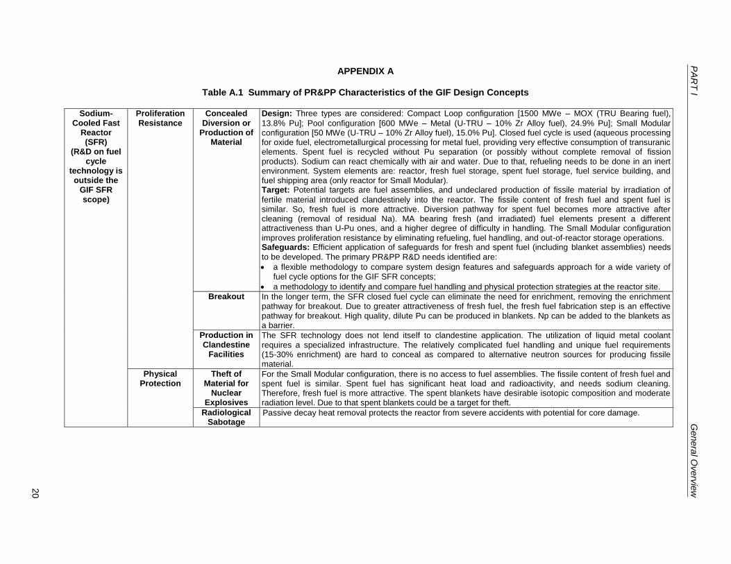
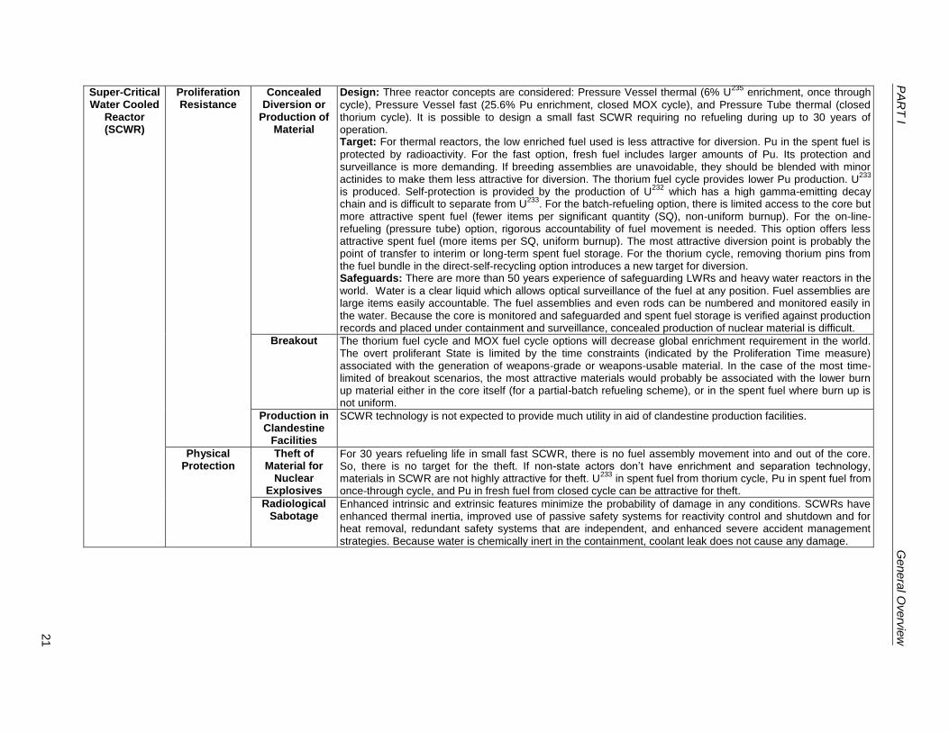
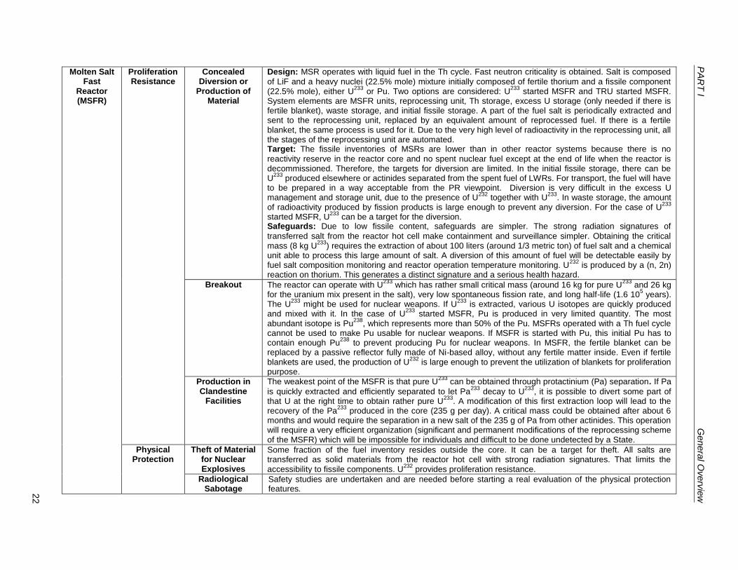
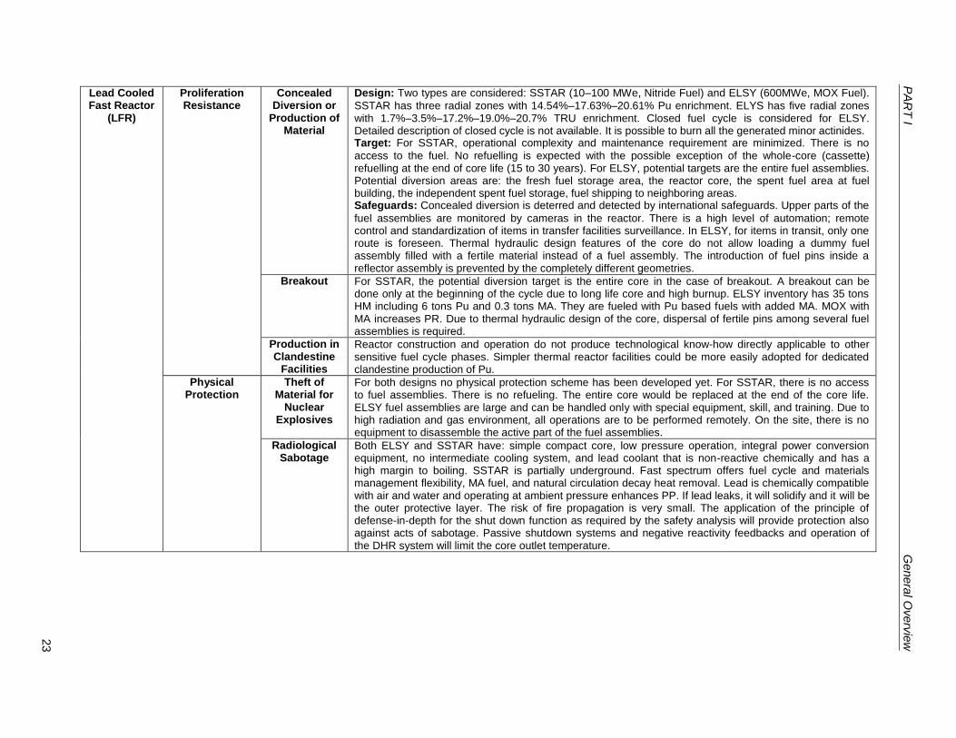
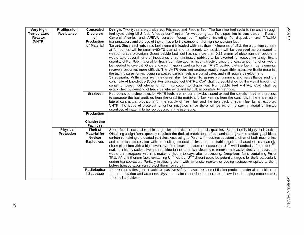


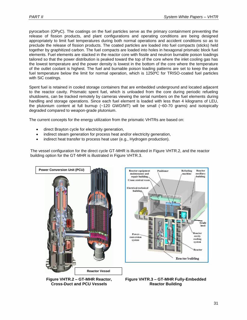
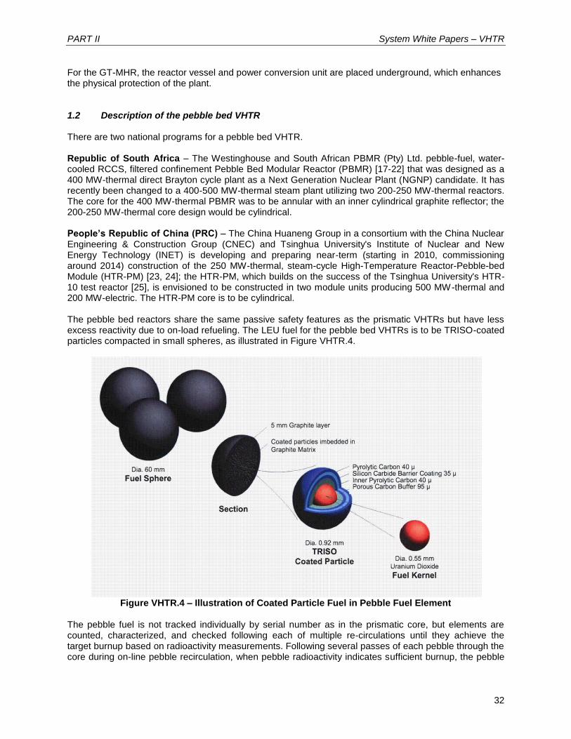
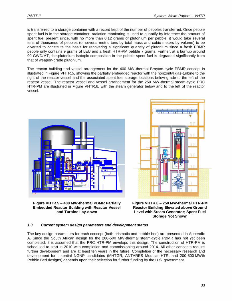

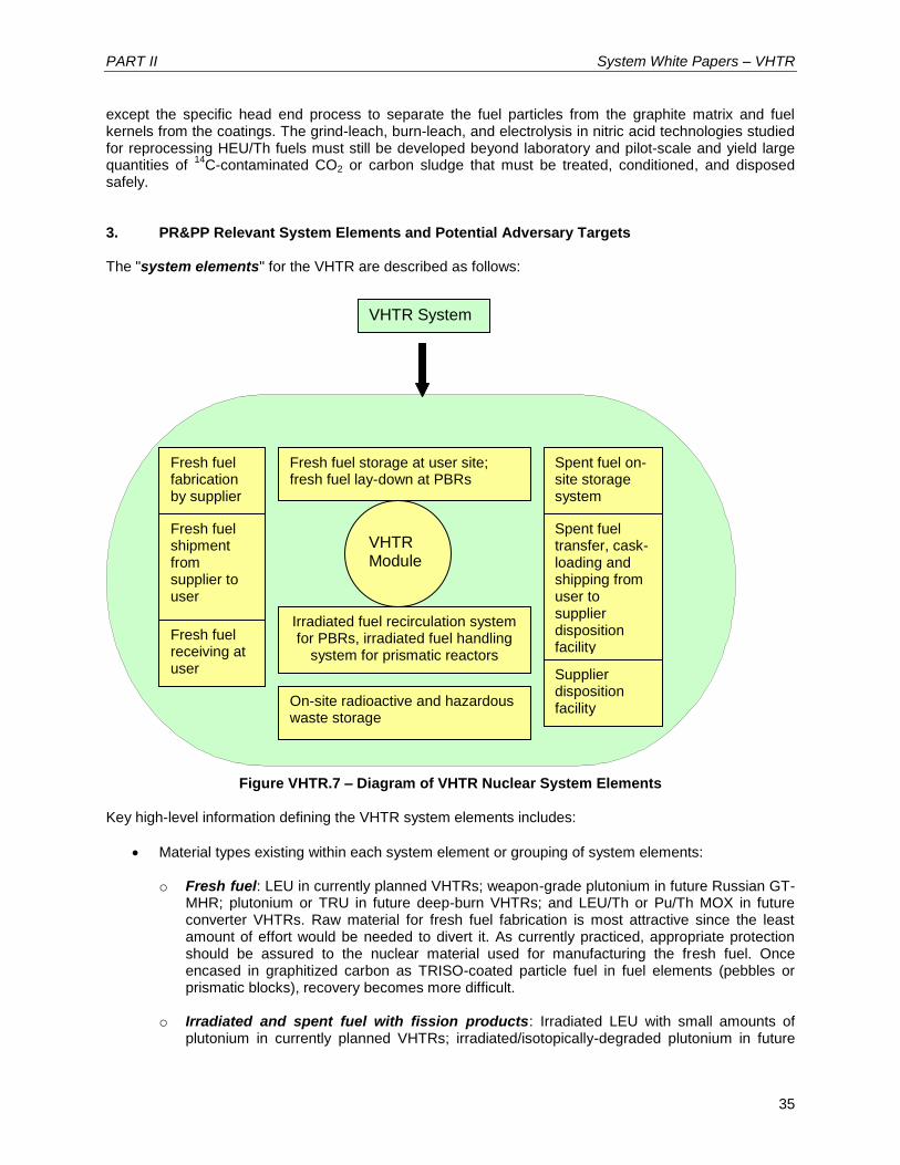


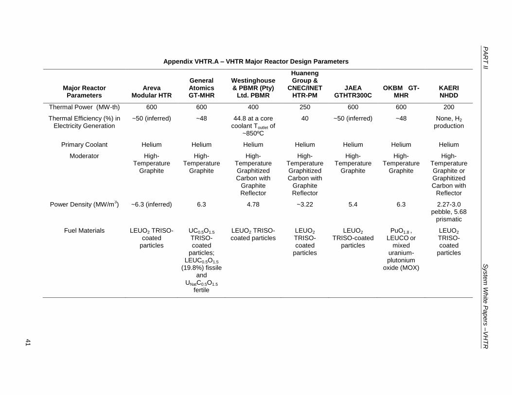
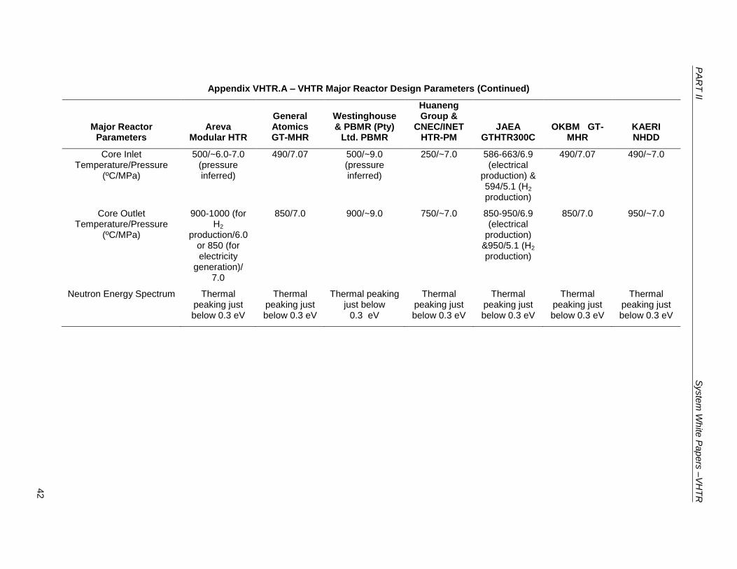


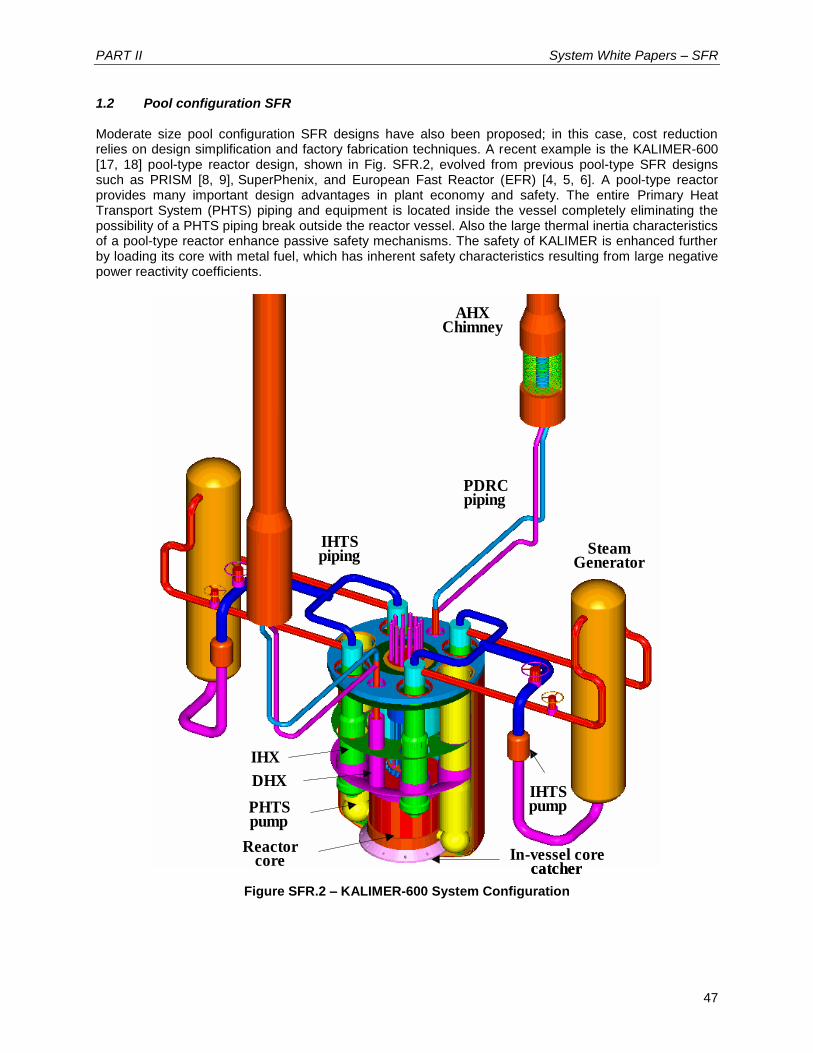


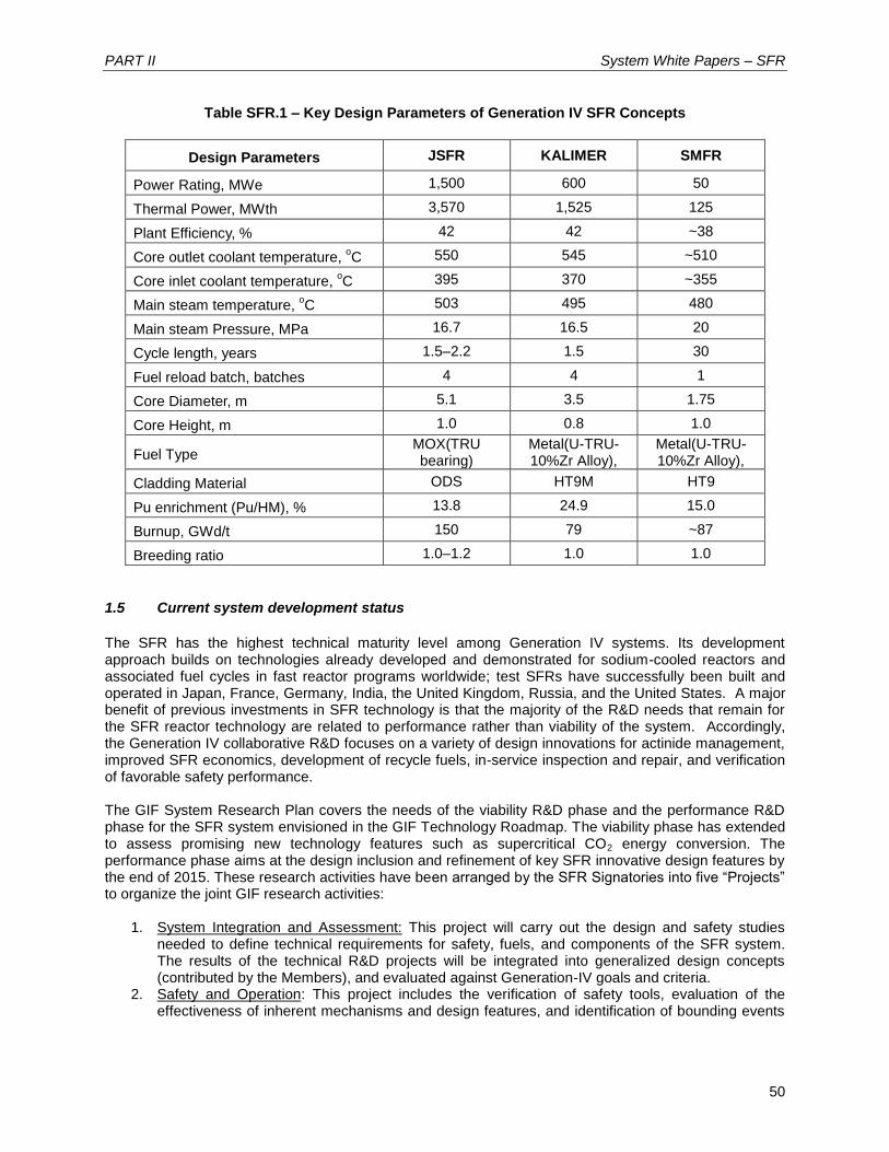

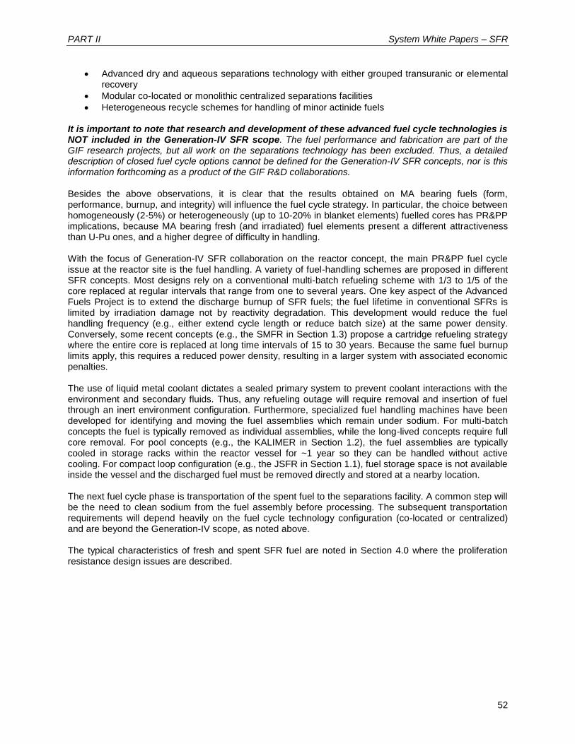


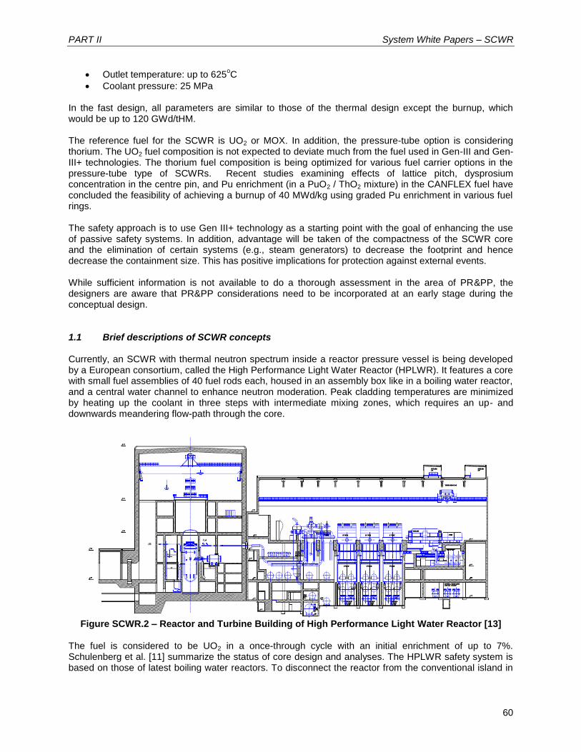

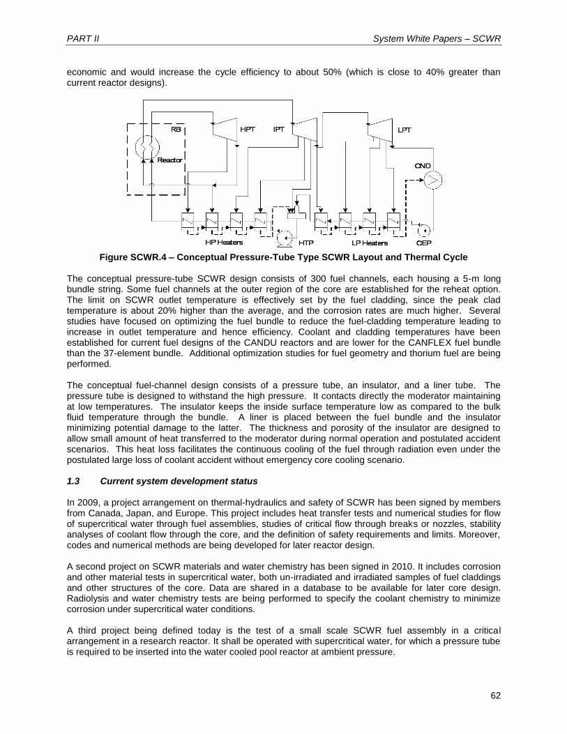

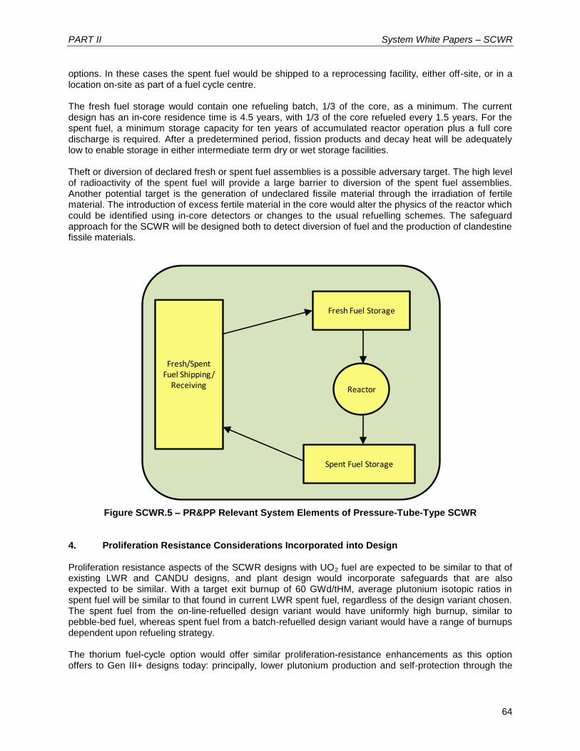


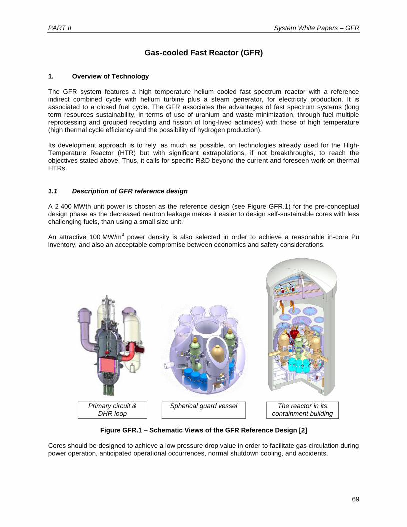


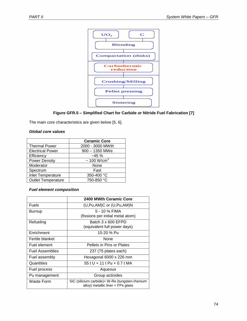
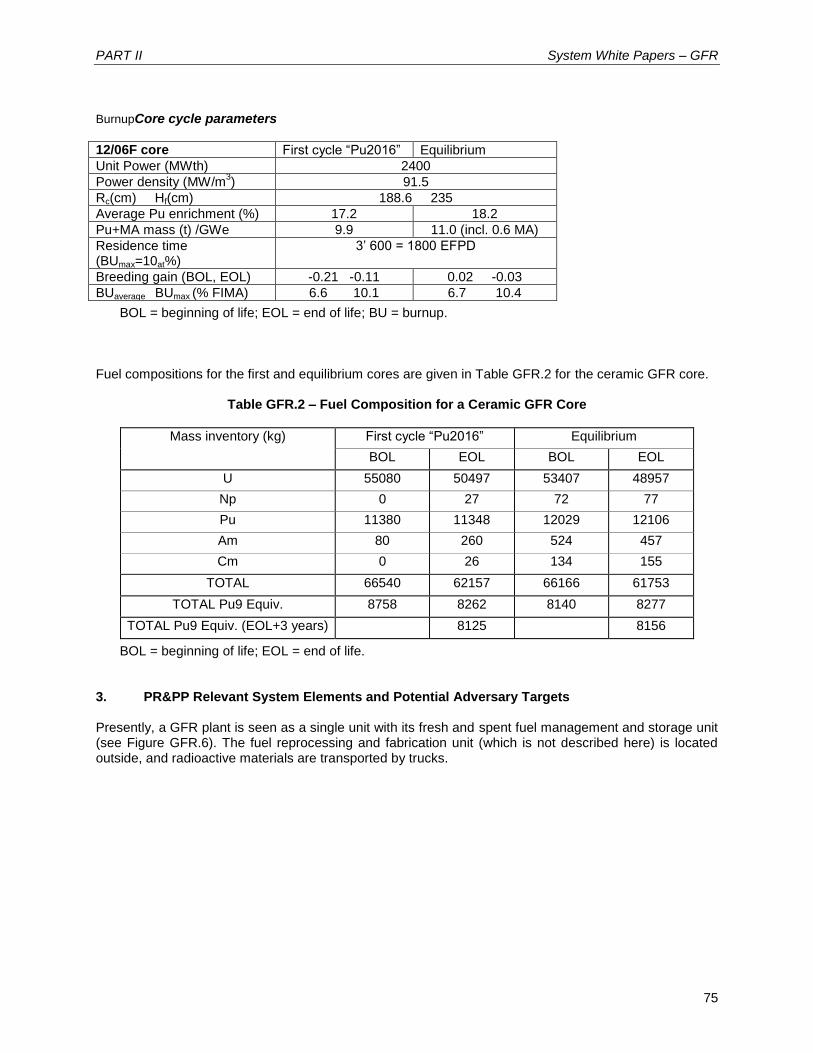

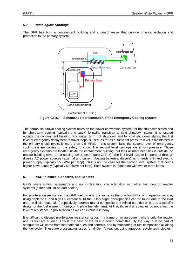


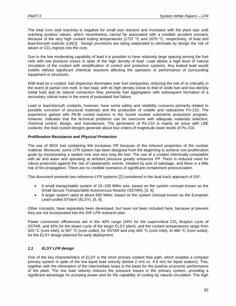
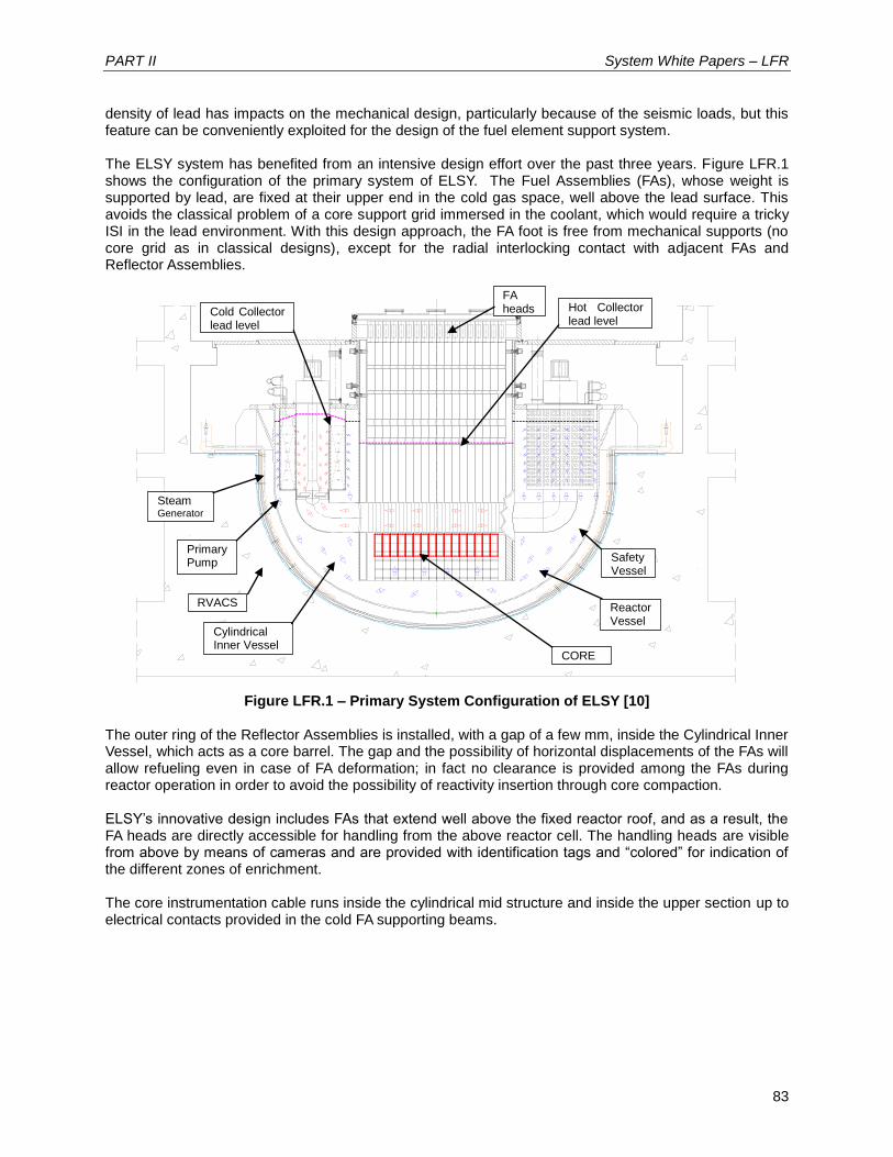


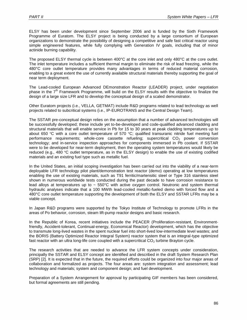
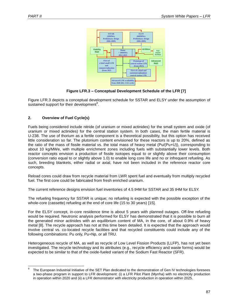


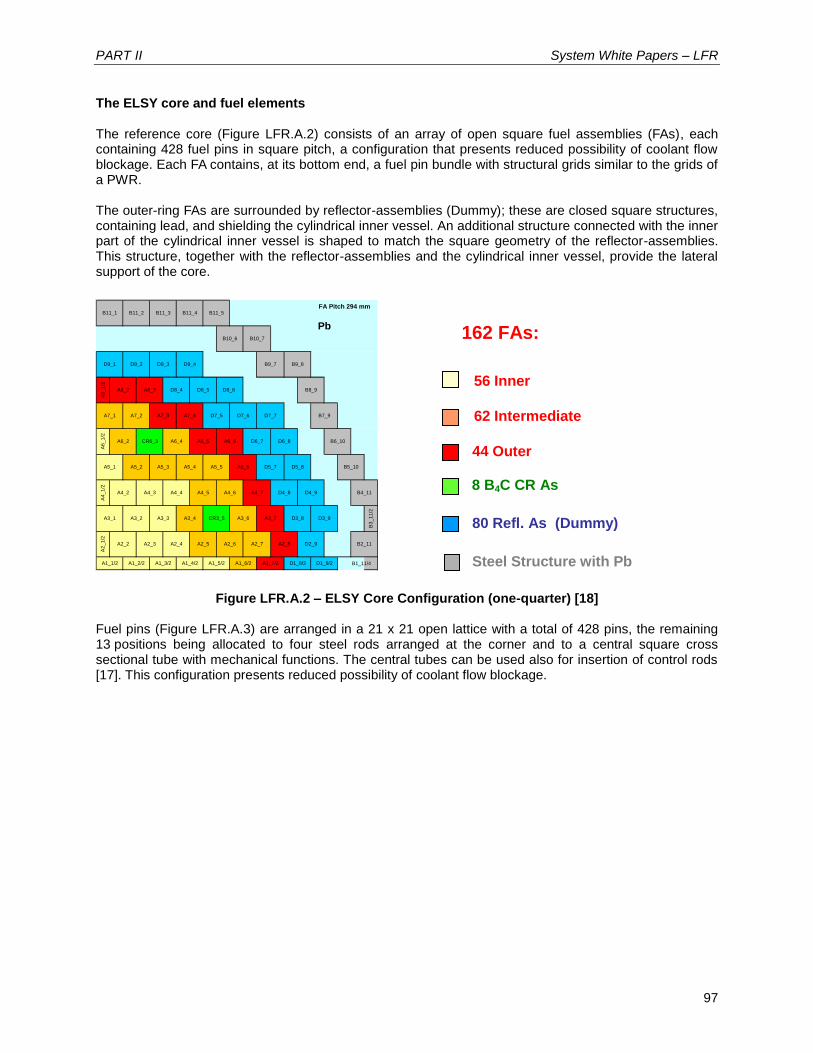
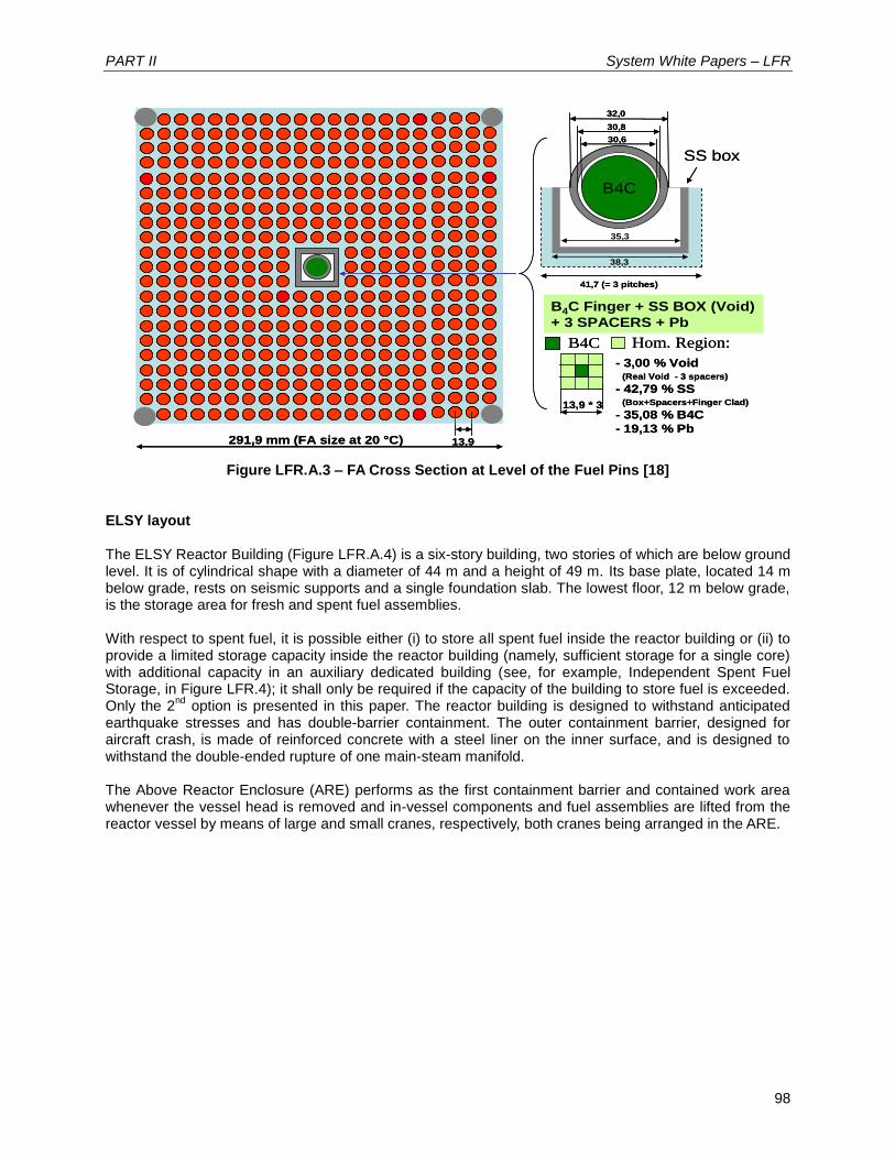


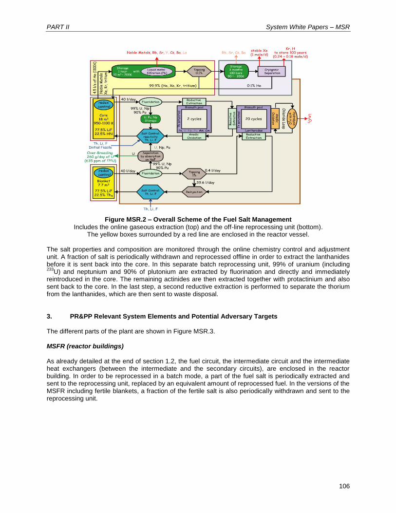


![FGL1 regulates acquired resistance to Gefitinib by ......cell proliferation play key roles in pathways that promote tumor cell proliferation and suppress their apoptosis [14, 15],](https://static.documents.pub/doc/80x56/611628ee2e8d510eac08c93e/fgl1-regulates-acquired-resistance-to-gefitinib-by-cell-proliferation-play.jpg)