134
BA059D/06/en/12.06 71036077 Valid as of version V 2.02.00 (Device software) Operating Instructions Proline Promass 83 Coriolis Mass Flow Measuring System 6

BA059D/06/en/12.06
71036077
Valid as of version
V 2.02.00 (Device software)
Operating Instructions
Proline Promass 83
Coriolis Mass Flow Measuring System
6
Brief operating instructions Proline Promass 83
2 Endress+Hauser
Brief operating instructions
These brief operating instructions show you how to configure your measuring device quickly and
easily:
! Note!
Always start troubleshooting with the checklist on Page 82, if faults occur after commissioning or
during operation. The routine takes you directly to the cause of the problem and the appropriate
remedial measures.
Safety instructions Page 7
▼
Installation Page 13
▼
Wiring Page 24
▼
Display and operating elements Page 31
▼
Commissioning with QUICK SETUP Page 52 ff.
You can commission your measuring device quickly and easily, using the special "Quick Setup"
menu. It enables you to configure important basic functions using the local display, for example
display language, measured variables, units of measures, type of signal, etc.
The following adjustments can be made separately as necessary:
– Zero point adjustment
– Density adjustment
▼
Application-specific commissioning Page 55 ff.
In the "Commissioning" Quick Setup you have the option of launching other, application-specific
Quick Setups, for instance the menu for measuring pulsating flow, etc.
▼
Customer-specific configuration Page 36 ff.
Complex measuring operations necessitate additional functions that you can configure as necessary
with the aid of the function matrix, and customize to suit your process parameters.
! Note!
All functions are described in detail, as is the function matrix itself, in the "Description of Device
Functions" manual, which is a separate part of these Operating Instructions.
▼
Data storage Page 64
The configuration of the transmitter can be stored on the integrated T-DAT data storage device.
! Note!
For time-saving commissioning, the settings stored in the T-DAT can be transmitted:
– For equivalent measuring points (equivalent configuration,)
– In the event of device/board replacement.
▼
More detailed configuration Page 65 ff.
The inputs and outputs can be modified on convertible boards by configuring the current inputs and
outputs and relay contacts. The F-Chip module gives the user the added option of using software
packages for diagnosis, concentration measurement and viscosity.
Proline Promass 83 Brief operating instructions
Endress+Hauser 3
QUICK SETUP "Commissioning"
! Note!
More detailed information on running Quick Setup menus, especially for devices without a local
display, can be found in the "Commissioning" section. → Page 53 ff.
a0004561-en
Fig. 1: "QUICK SETUP COMMISSIONING"- menu for straightforward configuration of the major device functions
04200400
6461
0421 6462
6463
6464
4200
4221
4222
4223
4225
4227
4226
4000
4001
4002
4004
4006
4003
4005
4201
4203
4204
4206
4208
4209
4205
4207
0422
646030013001
04040402
2000
1002B
++E +E
n
o
p
q
r
Esc
E+-
XXX.XXX.XX
m
s Batching
Yes
Yes
Yes
No
No
No
No
Configure another system unit ?
Current output n Freq./Pulse output n
Selection output type
Automatic configuration of display ?
Carrying out another Quick Setup ?
Quit
AssignCurrent output
Current span
Value 0/4 mA
Value 20 mA
Meas. mode Meas. mode
Meas. mode
Time constant
Time constantFailsafe mode
Failsafe mode
Failsafe mode
AssignFreq. output
End value freq.
Value F Low
Value F High
Output signal
AssignPulse output
Pulse value
Pulse width
Output signal
Operation Mode
Frequency Pulse
Automatic parameterization of the display
Reference Calculated
Fix. Density
Density
UnitRef. Density Exp. Coeff. Lin
Exp. Coeff. SQR
Reference temp.
Volume flow Corr. Vol. flowMass flow Density
Selection system units
Temperature Quit
UnitVolume flow
UnitCorr. Vol. flow
UnitMass flow
UnitDensity
UnitTemperature
UnitTotalizer
Corr. Vol.calculation
UnitTotalizer
Language
Pre-setting
Quick Setup
HOME-POSITION
QSCommission
Pulsating flow Gas measurement
Configure another output ?
Carrying out the selected Quick Setup
Selection pre-settings
Actual SettingsDeliver Settingsy

Brief operating instructions Proline Promass 83
4 Endress+Hauser
Proline Promass 83 Table of contents
Endress+Hauser 5
Table of contents
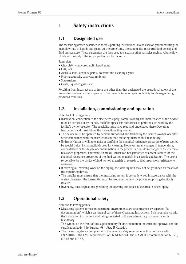
1 Safety instructions . . . . . . . . . . . . . . . . 7
1.1 Designated use . . . . . . . . . . . . . . . . . . . . . . . . . . . . 7
1.2 Installation, commissioning and operation . . . . . . . . 7
1.3 Operational safety . . . . . . . . . . . . . . . . . . . . . . . . . . 7
1.4 Return . . . . . . . . . . . . . . . . . . . . . . . . . . . . . . . . . . . 8
1.5 Notes on safety conventions and icons . . . . . . . . . . . 8
2 Identification . . . . . . . . . . . . . . . . . . . . 9
2.1 Device designation . . . . . . . . . . . . . . . . . . . . . . . . . 9
2.1.1 Nameplate of the transmitter . . . . . . . . . . . . 9
2.1.2 Nameplate of the sensor . . . . . . . . . . . . . . 10
2.1.3 Nameplate for connections . . . . . . . . . . . . 11
2.2 Certificates and approvals . . . . . . . . . . . . . . . . . . . 12
2.3 Registered trademarks . . . . . . . . . . . . . . . . . . . . . . 12
3 Installation . . . . . . . . . . . . . . . . . . . . . 13
3.1 Incoming acceptance, transport and storage . . . . . . 13
3.1.1 Incoming acceptance . . . . . . . . . . . . . . . . . 13
3.1.2 Transport . . . . . . . . . . . . . . . . . . . . . . . . . 13
3.1.3 Storage . . . . . . . . . . . . . . . . . . . . . . . . . . . 14
3.2 Installation conditions . . . . . . . . . . . . . . . . . . . . . . 14
3.2.1 Dimensions . . . . . . . . . . . . . . . . . . . . . . . . 14
3.2.2 Mounting location . . . . . . . . . . . . . . . . . . . 14
3.2.3 Orientation . . . . . . . . . . . . . . . . . . . . . . . . 16
3.2.4 Heating . . . . . . . . . . . . . . . . . . . . . . . . . . . 18
3.2.5 Thermal insulation . . . . . . . . . . . . . . . . . . 19
3.2.6 Inlet and outlet runs . . . . . . . . . . . . . . . . . 19
3.2.7 Vibrations . . . . . . . . . . . . . . . . . . . . . . . . . 19
3.2.8 Limiting flow . . . . . . . . . . . . . . . . . . . . . . . 19
3.3 Installation . . . . . . . . . . . . . . . . . . . . . . . . . . . . . . 20
3.3.1 Turning the transmitter housing . . . . . . . . 20
3.3.2 Installing the wall-mount housing . . . . . . . 21
3.3.3 Turning the local display . . . . . . . . . . . . . . 23
3.4 Post-installation check . . . . . . . . . . . . . . . . . . . . . . 23
4 Wiring . . . . . . . . . . . . . . . . . . . . . . . . 24
4.1 Connecting the remote version . . . . . . . . . . . . . . . 24
4.1.1 Connecting connecting cable for
sensor/transmitter . . . . . . . . . . . . . . . . . . . 24
4.1.2 Cable specification, connecting cable . . . . . 25
4.2 Connecting the measuring unit . . . . . . . . . . . . . . . 25
4.2.1 Transmitter connection . . . . . . . . . . . . . . . 25
4.2.2 Terminal assignment . . . . . . . . . . . . . . . . . 27
4.2.3 HART connection . . . . . . . . . . . . . . . . . . . 28
4.3 Degree of protection . . . . . . . . . . . . . . . . . . . . . . . 29
4.4 Post-connection check . . . . . . . . . . . . . . . . . . . . . . 30
5 Operation . . . . . . . . . . . . . . . . . . . . . . 31
5.1 Display and operating elements . . . . . . . . . . . . . . . 31
5.1.1 Readings displayed (operation mode) . . . . . 32
5.1.2 Additional display functions . . . . . . . . . . . . 32
5.1.3 Icons . . . . . . . . . . . . . . . . . . . . . . . . . . . . . 33
5.1.4 Controlling the batching processes using the
local display . . . . . . . . . . . . . . . . . . . . . . . . 35
5.2 Brief operating instructions to the function matrix . 36
5.2.1 General notes . . . . . . . . . . . . . . . . . . . . . . 37
5.2.2 Enabling the programming mode . . . . . . . . 37
5.2.3 Disabling the programming mode . . . . . . . . 37
5.3 Error messages . . . . . . . . . . . . . . . . . . . . . . . . . . . . 38
5.3.1 Type of error . . . . . . . . . . . . . . . . . . . . . . . 38
5.3.2 Error message type . . . . . . . . . . . . . . . . . . . 38
5.3.3 Confirming error messages . . . . . . . . . . . . . 39
5.4 Communication . . . . . . . . . . . . . . . . . . . . . . . . . . . 39
5.4.1 Operating options . . . . . . . . . . . . . . . . . . . 40
5.4.2 Current device description files . . . . . . . . . 41
5.4.3 Device and process variables . . . . . . . . . . . 42
5.4.4 Universal / Common practice
HART commands . . . . . . . . . . . . . . . . . . . 43
5.4.5 Device status / Error messages . . . . . . . . . . 48
5.4.6 Switching HART write protection
on and off . . . . . . . . . . . . . . . . . . . . . . . . . 51
6 Commissioning . . . . . . . . . . . . . . . . . . 52
6.1 Function check . . . . . . . . . . . . . . . . . . . . . . . . . . . 52
6.2 Switching on the measuring device . . . . . . . . . . . . 52
6.3 Quick Setup . . . . . . . . . . . . . . . . . . . . . . . . . . . . . . 53
6.3.1 Quick Setup "Commissioning" . . . . . . . . . . 53
6.3.2 "Pulsating Flow" Quick Setup menu . . . . . . 55
6.3.3 "Batching" Quick Setup menu . . . . . . . . . . 58
6.3.4 "Gas Measurement" Quick Setup menu . . . 62
6.3.5 Data backup/transmission . . . . . . . . . . . . . 64
6.4 Configuration . . . . . . . . . . . . . . . . . . . . . . . . . . . . 65
6.4.1 Two current outputs: active/passive . . . . 65
6.4.2 Current input: active/passive . . . . . . . . . . . 66
6.4.3 Relay contacts: Normally closed/
Normally open . . . . . . . . . . . . . . . . . . . . . . 67
6.4.4 Concentration measurement . . . . . . . . . . . 68
6.4.5 Advanced diagnostic functions . . . . . . . . . . 73
6.5 Adjustment . . . . . . . . . . . . . . . . . . . . . . . . . . . . . . 75
6.5.1 Zero point adjustment . . . . . . . . . . . . . . . . 75
6.5.2 Density adjustment . . . . . . . . . . . . . . . . . . 76
6.6 Purge and pressure monitoring connections . . . . . . 78
6.7 Data storage device (HistoROM), F-CHIP . . . . . . . . 78
6.7.1 HistoROM/S-DAT (sensor-DAT) . . . . . . . . 78
6.7.2 HistoROM/T-DAT (transmitter-DAT) . . . . 78
6.7.3 F-CHIP (Function-Chip) . . . . . . . . . . . . . . . 78
7 Maintenance . . . . . . . . . . . . . . . . . . . . 79
7.1 Exterior cleaning . . . . . . . . . . . . . . . . . . . . . . . . . . 79
7.2 Cleaning with pigs (Promass H, I, S, P) . . . . . . . . . . 79
7.3 Replacing seals . . . . . . . . . . . . . . . . . . . . . . . . . . . . 79
8 Accessories . . . . . . . . . . . . . . . . . . . . . 80
8.1 Device-specific accessories . . . . . . . . . . . . . . . . . . . 80
8.2 Measuring principle-specific accessories . . . . . . . . . 80
8.3 Communication-specific accessories . . . . . . . . . . . . 80
Proline Promass 83 Table of contents
6 Endress+Hauser
8.4 Service-specific accessories . . . . . . . . . . . . . . . . . . 81
9 Troubleshooting . . . . . . . . . . . . . . . . . 82
9.1 Troubleshooting instructions . . . . . . . . . . . . . . . . . 82
9.2 System error messages . . . . . . . . . . . . . . . . . . . . . . 83
9.3 Process error messages . . . . . . . . . . . . . . . . . . . . . . 88
9.4 Process errors without messages . . . . . . . . . . . . . . 90
9.5 Response of outputs to errors . . . . . . . . . . . . . . . . . 91
9.6 Spare parts . . . . . . . . . . . . . . . . . . . . . . . . . . . . . . 92
9.6.1 Removing and installing printed circuit boards
93
9.6.2 Replacing the device fuse . . . . . . . . . . . . . . 97
9.7 Return . . . . . . . . . . . . . . . . . . . . . . . . . . . . . . . . . . 97
9.8 Disposal . . . . . . . . . . . . . . . . . . . . . . . . . . . . . . . . 97
9.9 Software history . . . . . . . . . . . . . . . . . . . . . . . . . . 98
10 Technical data . . . . . . . . . . . . . . . . . . 100
10.1 Technical data at a glance . . . . . . . . . . . . . . . . . . 100
10.1.1 Applications . . . . . . . . . . . . . . . . . . . . . . . 100
10.1.2 Function and system design . . . . . . . . . . . 100
10.1.3 Input . . . . . . . . . . . . . . . . . . . . . . . . . . . . 100
10.1.4 Output . . . . . . . . . . . . . . . . . . . . . . . . . . 102
10.1.5 Power supply . . . . . . . . . . . . . . . . . . . . . . 103
10.1.6 Performance characteristics . . . . . . . . . . . 103
10.1.7 Operating conditions: Installation . . . . . . . 109
10.1.8 Operating conditions: Environment . . . . . 110
10.1.9 Operating conditions: Process . . . . . . . . . 111
10.1.10 Mechanical construction . . . . . . . . . . . . . 121
10.1.11 Human interface . . . . . . . . . . . . . . . . . . . 126
10.1.12 Certificates and approvals . . . . . . . . . . . . 127
10.1.13 Ordering information . . . . . . . . . . . . . . . 128
10.1.14 Accessories . . . . . . . . . . . . . . . . . . . . . . . 128
10.1.15 Documentation . . . . . . . . . . . . . . . . . . . 128
Index . . . . . . . . . . . . . . . . . . . . . . . . . . . . . 129
Proline Promass 83 Safety instructions
Endress+Hauser 7
1 Safety instructions
1.1 Designated use
The measuring device described in these Operating Instructions is to be used only for measuring the
mass flow rate of liquids and gases. At the same time, the system also measures fluid density and
fluid temperature. These parameters are then used to calculate other variables such as volume flow.
Fluids with widely differing properties can be measured.
Examples:
• Chocolate, condensed milk, liquid sugar
• Oils, fats
• Acids, alkalis, lacquers, paints, solvents and cleaning agents
• Pharmaceuticals, catalysts, inhibitors
• Suspensions
• Gases, liquefied gases, etc.
Resulting from incorrect use or from use other than that designated the operational safety of the
measuring devices can be suspended. The manufacturer accepts no liability for damages being
produced from this.
1.2 Installation, commissioning and operation
Note the following points:
• Installation, connection to the electricity supply, commissioning and maintenance of the device
must be carried out by trained, qualified specialists authorized to perform such work by the
facility's owner operator. The specialist must have read and understood these Operating
Instructions and must follow the instructions they contain.
• The device must be operated by persons authorized and trained by the facility's owner-operator.
Strict compliance with the instructions in the Operating Instruction is mandatory.
• Endress+Hauser is willing to assist in clarifying the chemical resistance properties of parts wetted
by special fluids, including fluids used for cleaning. However, small changes in temperature,
concentration or the degree of contamination in the process can result in changes of the chemical
resistance properties. Therefore, Endress+Hauser can not guarantee or accept liability for the
chemical resistance properties of the fluid wetted materials in a specific application. The user is
responsible for the choice of fluid wetted materials in regards to their in-process resistance to
corrosion.
• If carrying out welding work on the piping, the welding unit may not be grounded by means of
the measuring device.
• The installer must ensure that the measuring system is correctly wired in accordance with the
wiring diagrams. The transmitter must be grounded, unless the power supply is galvanically
isolated.
• Invariably, local regulations governing the opening and repair of electrical devices apply.
1.3 Operational safety
Note the following points:
• Measuring systems for use in hazardous environments are accompanied by separate "Ex
documentation", which is an integral part of these Operating Instructions. Strict compliance with
the installation instructions and ratings as stated in this supplementary documentation is
mandatory.
The symbol on the front of this supplementary Ex documentation indicates the approval and the
certification body ( 0 Europe, 2 USA, 1 Canada).
• The measuring device complies with the general safety requirements in accordance with
EN 61010-1, the EMC requirements of EN 61326/A1, and NAMUR Recommendation NE 21,
NE 43 and NE 53.
Safety instructions Proline Promass 83
8 Endress+Hauser
• For measuring systems used in SIL 2 applications, the separate manual on functional safety must
be observed.
• The manufacturer reserves the right to modify technical data without prior notice. Your
Endress+Hauser distributor will supply you with current information and updates to these
Operating Instructions.
1.4 Return
The following procedures must be carried out before a flowmeter requiring repair or calibration, for
example, is returned to Endress+Hauser:
• Always enclose a duly completed "Declaration of contamination" form. Only then can
Endress+Hauser transport, examine and repair a returned device.
• Enclose special handling instructions if necessary, for example a safety data sheet as per
EN 91/155/EEC.
• Remove all residues. Pay special attention to the grooves for seals and crevices which could
contain residues. This is particularly important if the substance is hazardous to health, e.g.
flammable, toxic, caustic, carcinogenic, etc.
With Promass A and Promass M the threaded process connections must first be removed from the
sensor and then cleaned.
! Note!
You will find a preprinted "Declaration of contamination" form at the back of this manual.
# Warning!
• Do not return a measuring device if you are not absolutely certain that all traces of hazardous
substances have been removed, e.g. substances which have penetrated crevices or diffused
through plastic.
• Costs incurred for waste disposal and injury (burns, etc.) due to inadequate cleaning will be
charged to the owner-operator.
1.5 Notes on safety conventions and icons
The devices are designed to meet state-of-the-art safety requirements, have been tested, and left the
factory in a condition in which they are safe to operate. The devices comply with the applicable
standards and regulations in accordance with EN 61010-1 "Protection Measures for Electrical
Equipment for Measurement, Control, Regulation and Laboratory Procedures". The devices can,
however, be a source of danger if used incorrectly or for other than the designated use.
Consequently, always pay particular attention to the safety instructions indicated in these Operating
Instructions by the following icons:
# Warning!
"Warning" indicates an action or procedure which, if not performed correctly, can result in injury
or a safety hazard. Comply strictly with the instructions and proceed with care.
" Caution!
"Caution" indicates an action or procedure which, if not performed correctly, can result in incorrect
operation or destruction of the device. Comply strictly with the instructions.
! Note!
"Note" indicates an action or procedure which, if not performed correctly, can have an indirect
effect on operation or trigger an unexpected response on the part of the device.
Proline Promass 83 Identification
Endress+Hauser 9
2 Identification
2.1 Device designation
The "Promass 80/83" flow measuring system consists of the following components:
• Promass 80 or 83 transmitter.
• Promass F, Promass M, Promass E, Promass A, Promass H, Promass I, Promass S or Promass P
sensor.
Two versions are available:
• Compact version: transmitter and sensor form a single mechanical unit.
• Remote version: transmitter and sensor are installed separately.
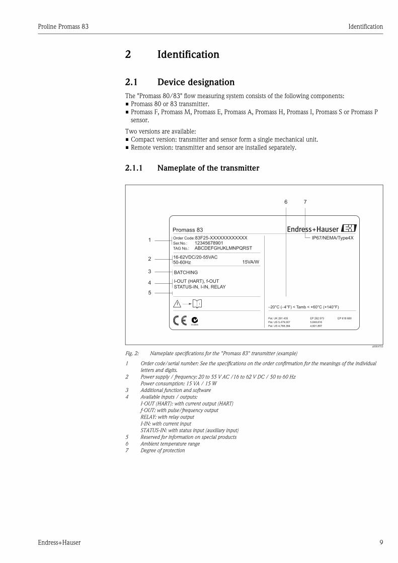
2.1.1 Nameplate of the transmitter
a0004703
Fig. 2: Nameplate specifications for the "Promass 83" transmitter (example)
1 Order code/serial number: See the specifications on the order confirmation for the meanings of the individual
letters and digits.
2 Power supply / frequency: 20 to 55 V AC /16 to 62 V DC / 50 to 60 Hz
Power consumption: 15 VA / 15 W
3 Additional function and software
4 Available inputs / outputs:
I-OUT (HART): with current output (HART)
f-OUT: with pulse/frequency output
RELAY: with relay output
I-IN: with current input
STATUS-IN: with status input (auxiliary input)
5 Reserved for information on special products
6 Ambient temperature range
7 Degree of protection
Promass 83
Order Code:
Ser.No.:
TAG No.:
16-62VDC/20-55VAC50-60Hz 15VA/W
IP67/NEMA/Type4X83F25-XXXXXXXXXXXX12345678901ABCDEFGHJKLMNPQRST
–20°C (–4°F) < Tamb < +60°C (+140°F)i
1
76
2
4
5
Pat. US 5,479,007
Pat. US 4,768,384
Pat. UK 261 435
5,648,616
4,801,897
EP 262 573 EP 618 680
I-OUT (HART), f-OUT
STATUS-IN, I-IN, RELAY
3 BATCHING
N12895
Identification Proline Promass 83
10 Endress+Hauser
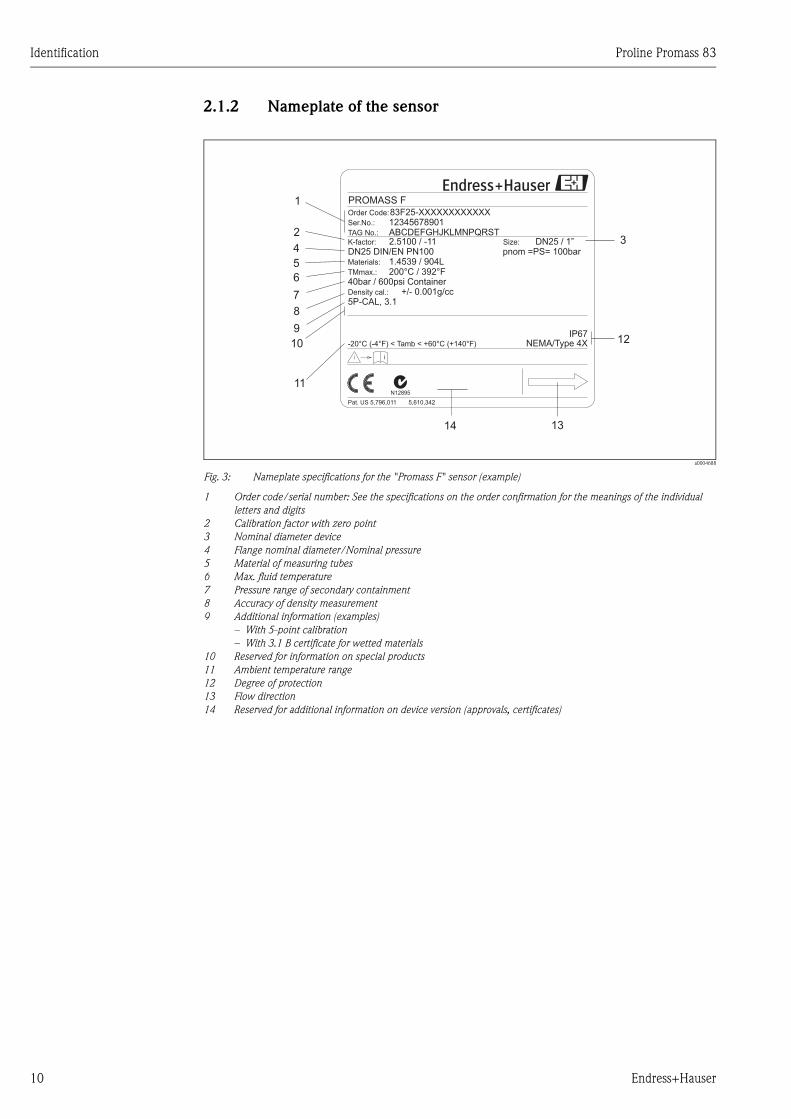
2.1.2 Nameplate of the sensor
a0004688
Fig. 3: Nameplate specifications for the "Promass F" sensor (example)
1 Order code/serial number: See the specifications on the order confirmation for the meanings of the individual
letters and digits
2 Calibration factor with zero point
3 Nominal diameter device
4 Flange nominal diameter/Nominal pressure
5 Material of measuring tubes
6 Max. fluid temperature
7 Pressure range of secondary containment
8 Accuracy of density measurement
9 Additional information (examples)
– With 5-point calibration
– With 3.1 B certificate for wetted materials
10 Reserved for information on special products
11 Ambient temperature range
12 Degree of protection
13 Flow direction
14 Reserved for additional information on device version (approvals, certificates)
1
2
4
5
6
7
8
912
1314
3
11
DN25 / 1”Size:
-20°C (-4°F) < Tamb < +60°C (+140°F)
Pat. US 5,796,011
i
NEMA/Type 4X
ABCDEFGHJKLMNPQRST12345678901
2.5100 / -11
83F25-XXXXXXXXXXXX
DN25 DIN/EN PN1001.4539 / 904L200°C / 392°F
40bar / 600psi Container
5P-CAL, 3.1+/- 0.001g/cc
K-factor:
TMmax.:
Materials:
Density cal.:
Ser.No.:
TAG No.:
Order Code:
5,610,342
IP67
pnom =PS= 100bar
N12895
PROMASS F
10
Proline Promass 83 Identification
Endress+Hauser 11
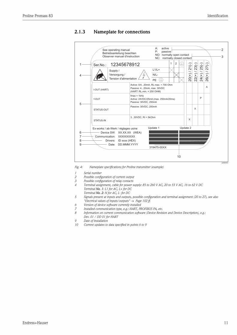
2.1.3 Nameplate for connections
a0000963
Fig. 4: Nameplate specifications for Proline transmitter (example)
1 Serial number
2 Possible configuration of current output
3 Possible configuration of relay contacts
4 Terminal assignment, cable for power supply: 85 to 260 V AC, 20 to 55 V AC, 16 to 62 V DC
Terminal No. 1: L1 for AC, L+ for DC
Terminal No. 2: N for AC, L- for DC
5 Signals present at inputs and outputs, possible configuration and terminal assignment (20 to 27), see also
"Electrical values of inputs/outputs" → Page 102 ff.
6 Version of device software currently installed
7 Installed communication type, e.g.: HART, PROFIBUS PA, etc.
8 Information on current communication software (Device Revision and Device Description), e.g.:
Dev. 01 / DD 01 for HART
9 Date of installation
10 Current updates to data specified in points 6 to 9
Communication:
Drivers:
Device SW:
ID xxxx (HEX)
XX.XX.XX (WEA)
XXXXXXXXXX
Date: DD.MMM.YYYY
Ex-works / ab-Werk / réglages usine
26(+
)/27(-
)
NC:
Versorgung /
Tension d'alimentation
Observer manuel d'instruction
See operating manualBetriebsanleitung beachten
Active: 0/4...20mA, RL max. = 700 Ohm
Passive: 4...20mA, max. 30VDC
Passive: 30VDC, 250mA
Active: 24VDC/25mA (max. 250mA/20ms)
Passive: 30VDC, 250mA
(HART: RL.min. = 250 OHM)
fmax = 1kHz
3...30VDC, Ri = 5kOhm
f-OUT
I-OUT (HART)
12345678912Ser.No.:
Supply /
24(+
)/25(-
)
22(+
)/23(-
)
20(+
)/21(-
)
N/L-
PE
A:
NO:P:
L1/L+
1 2
319475-00XX
A
P
activepassivenormally open contactnormally closed contact
XSTATUS-OUT
STATUS-IN X
Update 1 Update 2
2
3
1
4
5
6
7
8
9
10

Identification Proline Promass 83
12 Endress+Hauser
2.2 Certificates and approvals
The devices are designed in accordance with good engineering practice to meet state-of-the-art
safety requirements, have been tested, and left the factory in a condition in which they are safe to
operate. The devices comply with the applicable standards and regulations in accordance with EN
61010-1 "Protection Measures for Electrical Equipment for Measurement, Control, Regulation and
Laboratory Procedures" and with the EMC requirements of EN 61326/A1.
The measuring system described in these Operating Instructions thus complies with the statutory
requirements of the EC Directives. Endress+Hauser confirms successful testing of the device by
affixing to it the CE mark.
The measuring system is in conformity with the EMC requirements of the "Australian
Communications and Media Authority (ACMA)".
2.3 Registered trademarks
KALREZ® and VITON®
Registered trademarks of E.I. Du Pont de Nemours & Co., Wilmington, USA
TRI-CLAMP®
Registered trademark of Ladish & Co., Inc., Kenosha, USA
SWAGELOK®
Registered trademark of Swagelok & Co., Solon, USA
HART®
Registered trademark of HART Communication Foundation, Austin, USA
HistoROM™, S-DAT®, T-DAT™, F-CHIP®, FieldCare®, ToF Tool - Fieldtool® Package,
Fieldcheck®, Applicator®
Registered or registration-pending trademarks of Endress+Hauser Flowtec AG, Reinach, CH
Proline Promass 83 Installation
Endress+Hauser 13
3 Installation
3.1 Incoming acceptance, transport and storage
3.1.1 Incoming acceptance
On receipt of the goods, check the following points:
• Check the packaging and the contents for damage.
• Check the shipment, make sure nothing is missing and that the scope of supply matches your
order.
3.1.2 Transport
The following instructions apply to unpacking and to transporting the device to its final location:
• Transport the devices in the containers in which they are delivered.
• The covers or caps fitted to the process connections prevent mechanical damage to the sealing
faces and the ingress of foreign matter to the measuring tube during transportation and storage.
Consequently, do not remove these covers or caps until immediately before installation.
• Do not lift measuring devices of nominal diameters > DN 40 (> 1½") by the transmitter housing
or the connection housing in the case of the remote version (Fig. 5). - Use webbing slings slung
round the two process connections. Do not use chains, as they could damage the housing.
• In the case of the Promass M / DN 80 sensor, use only the lifting eyes on the flanges to lift the
assembly!
# Warning!
Risk of injury if the measuring device slips. The center of gravity of the assembled measuring device
might be higher than the points around which the slings are slung.
At all times, therefore, make sure that the device does not unexpectedly turn around its axis or slip.
a0004294
Fig. 5: Instructions for transporting sensors with > DN 40 (> 1½")
Installation Proline Promass 83
14 Endress+Hauser
3.1.3 Storage
Note the following points:
• Pack the measuring device in such a way as to protect it reliably against impact for storage (and
transportation). The original packaging provides optimum protection.
• The permissible storage temperature is –40 to +80 °C (–40 °F to +176 °F), preferably +20 °C
(+68 °F).
• Do not remove the protective covers or caps on the process connections until you are ready to
install the device.
• The measuring device must be protected against direct sunlight during storage in order to avoid
unacceptably high surface temperatures.
3.2 Installation conditions
Note the following points:
• No special measures such as supports are necessary. External forces are absorbed by the
construction of the instrument, for example the secondary containment.
• The high oscillation frequency of the measuring tubes ensures that the correct operation of the
measuring system is not influenced by pipe vibrations.
• No special precautions need to be taken for fittings which create turbulence (valves, elbows,
T-pieces, etc.), as long as no cavitation occurs.
• For mechanical reasons and in order to protect the pipe, it is advisable to support heavy sensors.
3.2.1 Dimensions
All the dimensions and lengths of the sensor and transmitter are provided in the separate
documentation "Technical Information"
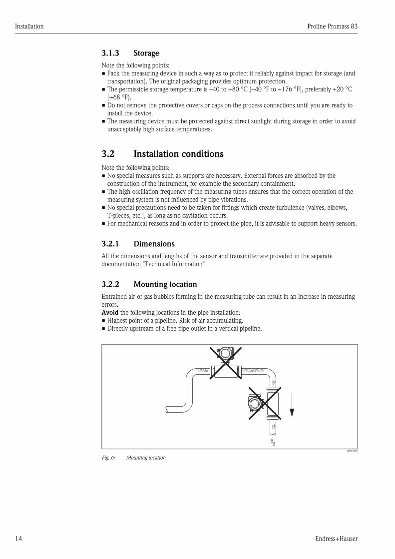
3.2.2 Mounting location
Entrained air or gas bubbles forming in the measuring tube can result in an increase in measuring
errors.
Avoid the following locations in the pipe installation:
• Highest point of a pipeline. Risk of air accumulating.
• Directly upstream of a free pipe outlet in a vertical pipeline.
a0003605
Fig. 6: Mounting location
Proline Promass 83 Installation
Endress+Hauser 15
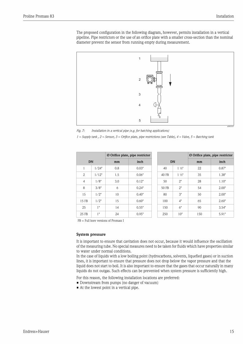
The proposed configuration in the following diagram, however, permits installation in a vertical
pipeline. Pipe restrictors or the use of an orifice plate with a smaller cross-section than the nominal
diameter prevent the sensor from running empty during measurement.
a0003597
Fig. 7: Installation in a vertical pipe (e.g. for batching applications)
1 = Supply tank , 2 = Sensor, 3 = Orifice plate, pipe restrictions (see Table), 4 = Valve, 5 = Batching tank
System pressure
It is important to ensure that cavitation does not occur, because it would influence the oscillation
of the measuring tube. No special measures need to be taken for fluids which have properties similar
to water under normal conditions.
In the case of liquids with a low boiling point (hydrocarbons, solvents, liquefied gases) or in suction
lines, it is important to ensure that pressure does not drop below the vapor pressure and that the
liquid does not start to boil. It is also important to ensure that the gases that occur naturally in many
liquids do not outgas. Such effects can be prevented when system pressure is sufficiently high.
For this reason, the following installation locations are preferred:
• Downstream from pumps (no danger of vacuum)
• At the lowest point in a vertical pipe.
1
2
3
4
5
DN
Ø Orifice plate, pipe restrictor
DN
Ø Orifice plate, pipe restrictor
mm inch mm inch
1 1/24" 0.8 0.03" 40 1 ½" 22 0.87"
2 1/12" 1.5 0.06" 40 FB 1 ½" 35 1.38"
4 1/8" 3.0 0.12" 50 2" 28 1.10"
8 3/8" 6 0.24" 50 FB 2" 54 2.00"
15 1/2" 10 0.40" 80 3" 50 2.00"
15 FB 1/2" 15 0.60" 100 4" 65 2.60"
25 1" 14 0.55" 150 6" 90 3.54"
25 FB 1" 24 0.95" 250 10" 150 5.91"
FB = Full bore versions of Promass I
Installation Proline Promass 83
16 Endress+Hauser
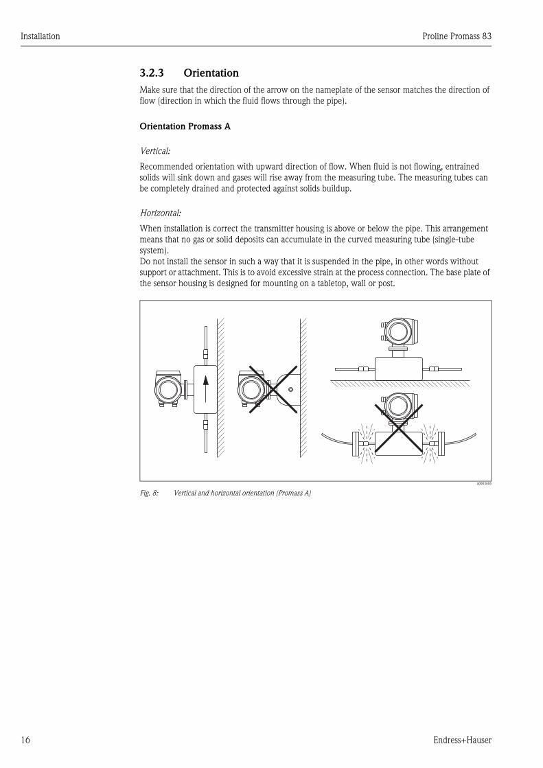
3.2.3 Orientation
Make sure that the direction of the arrow on the nameplate of the sensor matches the direction of
flow (direction in which the fluid flows through the pipe).
Orientation Promass A
Vertical:
Recommended orientation with upward direction of flow. When fluid is not flowing, entrained
solids will sink down and gases will rise away from the measuring tube. The measuring tubes can
be completely drained and protected against solids buildup.
Horizontal:
When installation is correct the transmitter housing is above or below the pipe. This arrangement
means that no gas or solid deposits can accumulate in the curved measuring tube (single-tube
system).
Do not install the sensor in such a way that it is suspended in the pipe, in other words without
support or attachment. This is to avoid excessive strain at the process connection. The base plate of
the sensor housing is designed for mounting on a tabletop, wall or post.
a0003606
Fig. 8: Vertical and horizontal orientation (Promass A)
Proline Promass 83 Installation
Endress+Hauser 17
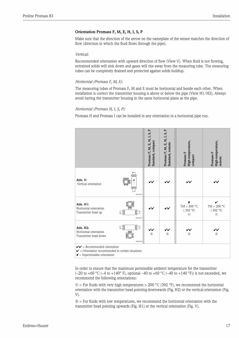
Orientation Promass F, M, E, H, I, S, P
Make sure that the direction of the arrow on the nameplate of the sensor matches the direction of
flow (direction in which the fluid flows through the pipe).
Vertical:
Recommended orientation with upward direction of flow (View V). When fluid is not flowing,
entrained solids will sink down and gases will rise away from the measuring tube. The measuring
tubes can be completely drained and protected against solids buildup.
Horizontal (Promass F, M, E):
The measuring tubes of Promass F, M and E must be horizontal and beside each other. When
installation is correct the transmitter housing is above or below the pipe (View H1/H2). Always
avoid having the transmitter housing in the same horizontal plane as the pipe.
Horizontal (Promass H, I, S, P):
Promass H and Promass I can be installed in any orientation in a horizontal pipe run.
In order to ensure that the maximum permissible ambient temperature for the transmitter
(–20 to +60 °C (–4 to +140° F), optional –40 to +60 °C (–40 to +140 °F)) is not exceeded, we
recommend the following orientations:
m = For fluids with very high temperatures > 200 °C (392 °F), we recommend the horizontal
orientation with the transmitter head pointing downwards (Fig. H2) or the vertical orientation (Fig.
V).
n = For fluids with low temperatures, we recommend the horizontal orientation with the
transmitter head pointing upwards (Fig. H1) or the vertical orientation (Fig. V).
Pro
mass
F,
M,
E,
H,
I, S
, P
Sta
nd
ard
, com
pact
Pro
mass
F,
M,
E,
H,
I, S
, P
Sta
nd
ard
, re
mote
Pro
mass
F
Hig
h-t
em
pera
ture
,
com
pact
Pro
mass
F
Hig
h-t
em
pera
ture
,
rem
ote
Abb. V:
Vertical orientation
a0004572
ÃÃ ÃÃ ÃÃ ÃÃ
Abb. H1:
Horizontal orientation
Transmitter head up
a0004576
ÃÃ ÃÃ
✘
TM > 200 °C
( 392 °F)
m
ÃTM > 200 °C
( 392 °F)
m
Abb. H2:
Horizontal orientation
Transmitter head down
a0004580
ÃÃn
ÃÃn
ÃÃn
ÃÃn
ÃÃ = Recommended orientation
à = Orientation recommended in certain situations
✘ = Impermissible orientation
Installation Proline Promass 83
18 Endress+Hauser
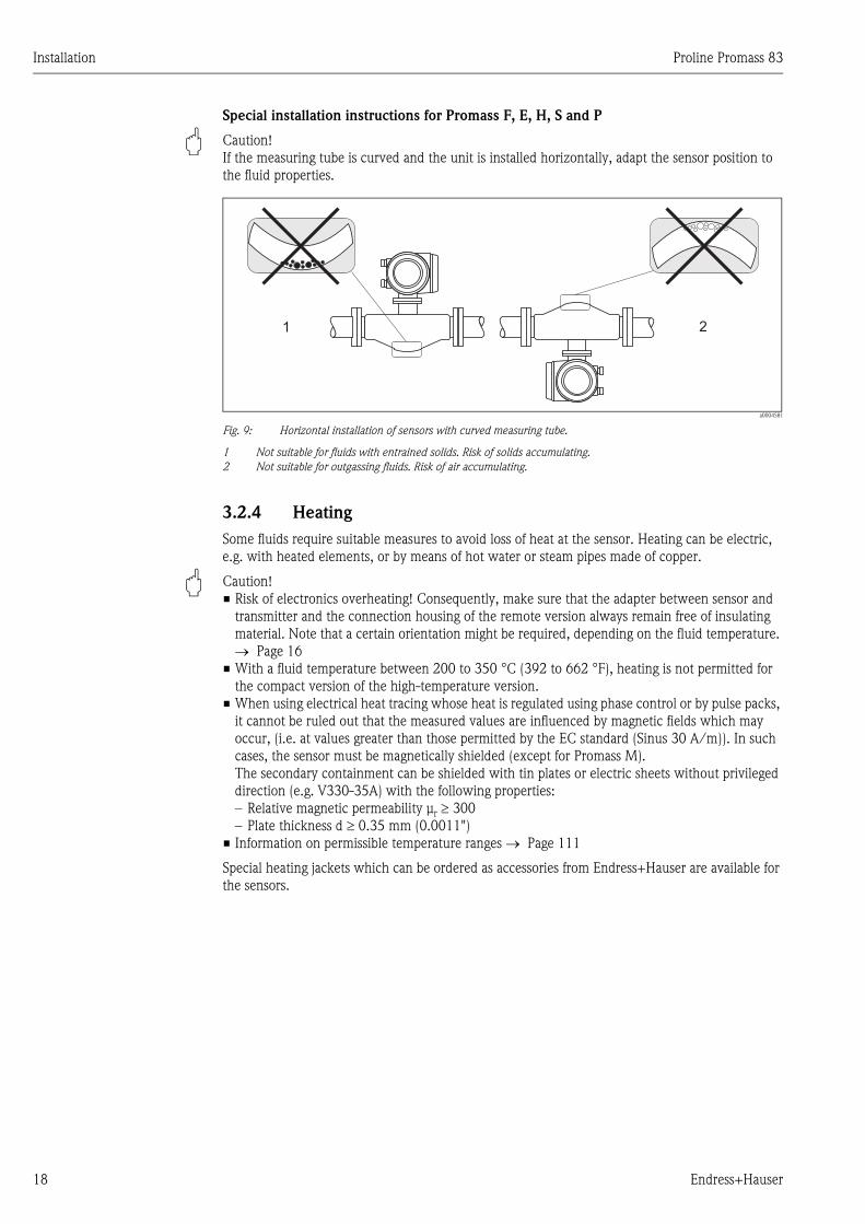
Special installation instructions for Promass F, E, H, S and P
" Caution!
If the measuring tube is curved and the unit is installed horizontally, adapt the sensor position to
the fluid properties.
a0004581
Fig. 9: Horizontal installation of sensors with curved measuring tube.
1 Not suitable for fluids with entrained solids. Risk of solids accumulating.
2 Not suitable for outgassing fluids. Risk of air accumulating.
3.2.4 Heating
Some fluids require suitable measures to avoid loss of heat at the sensor. Heating can be electric,
e.g. with heated elements, or by means of hot water or steam pipes made of copper.
" Caution!
• Risk of electronics overheating! Consequently, make sure that the adapter between sensor and
transmitter and the connection housing of the remote version always remain free of insulating
material. Note that a certain orientation might be required, depending on the fluid temperature.
→ Page 16
• With a fluid temperature between 200 to 350 °C (392 to 662 °F), heating is not permitted for
the compact version of the high-temperature version.
• When using electrical heat tracing whose heat is regulated using phase control or by pulse packs,
it cannot be ruled out that the measured values are influenced by magnetic fields which may
occur, (i.e. at values greater than those permitted by the EC standard (Sinus 30 A/m)). In such
cases, the sensor must be magnetically shielded (except for Promass M).
The secondary containment can be shielded with tin plates or electric sheets without privileged
direction (e.g. V330-35A) with the following properties:
– Relative magnetic permeability μr ≥ 300
– Plate thickness d ≥ 0.35 mm (0.0011")
• Information on permissible temperature ranges → Page 111
Special heating jackets which can be ordered as accessories from Endress+Hauser are available for
the sensors.
1 2
Proline Promass 83 Installation
Endress+Hauser 19
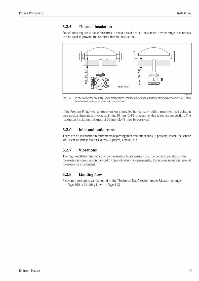
3.2.5 Thermal insulation
Some fluids require suitable measures to avoid loss of heat at the sensor. A wide range of materials
can be used to provide the required thermal insulation.
a0004614-ae
Fig. 10: In the case of the Promass F high-temperature version, a maximum insulation thickness of 60 mm (2.4") must
be observed in the area of the electronics/neck.
If the Promass F high-temperature version is installed horizontally (with transmitter head pointing
upwards), an insulation thickness of min. 10 mm (0.4") is recommended to reduce convection. The
maximum insulation thickness of 60 mm (2.4") must be observed.
3.2.6 Inlet and outlet runs
There are no installation requirements regarding inlet and outlet runs. If possible, install the sensor
well clear of fittings such as valves, T-pieces, elbows, etc.
3.2.7 Vibrations
The high oscillation frequency of the measuring tubes ensures that the correct operation of the
measuring system is not influenced by pipe vibrations. Consequently, the sensors require no special
measures for attachment.
3.2.8 Limiting flow
Relevant information can be found in the "Technical Data" section under Measuring range
→ Page 100 or Limiting flow → Page 112
Esc
E-
+
ma
x.6
0(2
.4)
ma
x.6
0(2
.4)
mm (inch)
Installation Proline Promass 83
20 Endress+Hauser
3.3 Installation
3.3.1 Turning the transmitter housing
Turning the aluminum field housing
# Warning!
The turning mechanism in devices with EEx d/de or FM/CSA Cl. I Div. 1 classification is not the
same as that described here. The procedure for turning these housings is described in the Ex-specific
documentation.
1. Loosen the two securing screws.
2. Turn the bayonet catch as far as it will go.
3. Carefully lift the transmitter housing as far as it will go.
4. Turn the transmitter housing to the desired position (max. 2 x 90° in either direction).
5. Lower the housing into position and reengage the bayonet catch.
6. Retighten the two securing screws.
a0004302
Fig. 11: Turning the transmitter housing (aluminum field housing)
Turning the stainless steel field housing
1. Loosen the two securing screws.
2. Carefully lift the transmitter housing as far as it will go.
3. Turn the transmitter housing to the desired position (max. 2 x 90° in either direction).
4. Lower the housing into position.
5. Retighten the two securing screws.
a0004303
Fig. 12: Turning the transmitter housing (stainless steel field housing)
3
5
61
2 4
1 2
3
4
5
Proline Promass 83 Installation
Endress+Hauser 21
3.3.2 Installing the wall-mount housing
There are various ways of installing the wall-mount housing:
• Mounted directly on the wall
• Installation in control panel (separate mounting set, accessories) → Page 22
• Pipe mounting (separate mounting set, accessories) → Page 22
" Caution!
• Make sure that ambient temperature does not go beyond the permissible range
(– 20 to +60 °C (–4 to + °140 F), optional – 40 to +60 °C (–40 to +140 °F)). Install the device
in a shady location. Avoid direct sunlight.
• Always install the wall-mount housing in such a way that the cable entries are pointing down.
Mounted directly on the wall
1. Drill the holes as illustrated in the diagram.
2. Remove the cover of the connection compartment (a).
3. Push the two securing screws (b) through the appropriate bores (c) in the housing.
– Securing screws (M6): max. Ø 6.5 mm (0.26")
– Screw head: max. Ø 10.5 mm (0.41")
4. Secure the transmitter housing to the wall as indicated.
5. Screw the cover of the connection compartment (a) firmly onto the housing.
a0001130
Fig. 13: Mounted directly on the wall
a
bc c
90 (3.54)
35 (1.38)
192 (7.56)
81.5
(3.2
)
mm (inch)
Installation Proline Promass 83
22 Endress+Hauser
Installation in control panel
1. Prepare the opening in the panel as illustrated in the diagram.
2. Slide the housing into the opening in the panel from the front.
3. Screw the fasteners onto the wall-mount housing.
4. Screw threaded rods into holders and tighten until the housing is solidly seated on the panel
wall. Afterwards, tighten the locking nuts.
Additional support is not necessary.
a0001131
Fig. 14: Panel installation (wall-mount housing)
Pipe mounting
The assembly should be performed by following the instructions in the diagram.
" Caution!
If a warm pipe is used for installation, make sure that
the housing temperature does not exceed the max. permitted value of +60 °C (+140 °F).
a0001132
Fig. 15: Pipe mounting (wall-mount housing)
245 (9.65)
~110 (~4.33)
210 (8.27)
+0.5 (+0.019)–0.5 (–0.019)
+0.5 (+0.019)–0.5 (–0.019)
mm (inch)
Ø 20…70(Ø 0.79…2.75)
~ ~ 6.1)155 (
mm (inch)
Proline Promass 83 Installation
Endress+Hauser 23
3.3.3 Turning the local display
1. Unscrew cover of the electronics compartment from the transmitter housing.
2. Press the side latches on the display module and remove the module from the electronics
compartment cover plate.
3. Rotate the display to the desired position (max. 4 x 45 ° in both directions), and reset it onto
the electronics compartment cover plate.
4. Screw the cover of the electronics compartment firmly back onto the transmitter housing.
a0003236
Fig. 16: Turning the local display (field housing)
3.4 Post-installation check
Perform the following checks after installing the measuring device in the pipe:
4 x 45°
Device condition and specifications Notes
Is the device damaged (visual inspection)? -
Does the device correspond to specifications at the measuring point, including
process temperature and pressure, ambient temperature, measuring range, etc.?
→ Page 7 ff.
Installation instructions Notes
Does the arrow on the sensor nameplate match the direction of flow through the
pipe?
-
Are the measuring point number and labeling correct (visual inspection)? -
Is the orientation chosen for the sensor correct, in other words suitable for sensor
type, fluid properties (outgassing, with entrained solids) and fluid temperature?
→ Page 14 ff.
Process environment / process conditions Notes
Is the measuring device protected against moisture and direct sunlight? -
Wiring Proline Promass 83
24 Endress+Hauser
4 Wiring
# Warning!
When connecting Ex-certified devices, see the notes and diagrams in the Ex-specific supplement to
these Operating Instructions. Please do not hesitate to contact your Endress+Hauser sales office if
you have any questions.
4.1 Connecting the remote version
4.1.1 Connecting connecting cable for sensor/transmitter
# Warning!
• Risk of electric shock. Switch off the power supply before opening the device.
Do not install or wire the device while it is connected to the power supply.
Failure to comply with this precaution can result in irreparable damage to the electronics.
• Risk of electric shock. Connect the protective ground to the ground terminal on the housing
before the power supply is applied.
• You may only connect the sensor to the transmitter with the same serial number. Communication
errors can occur if this is not observed when connecting the devices.
1. Remove the connection compartment cover (a) by loosening the fixing screws on the
transmitter and sensor housing.
2. Feed the connecting cable (b) through the appropriate cable runs.
3. Establish the connections between sensor and transmitter in accordance with the wiring
diagram:
– see Fig. 17
– See wiring diagram in screw cap
4. Screw the connection compartment cover (a) back onto the sensor and transmitter housing.
a0003681
Fig. 17: Connecting the remote version
a Wall-mount housing: non-hazardous area and ATEX II3G / Zone 2 → see separate Ex documentation
b Wall-mount housing: ATEX II2G / Zone 1 /FM/CSA → see separate Ex documentation
c Remote version, flange version
Terminal No.: 4/5 = gray; 6/7 = green; 8 = yellow; 9/10 = pink; 11/12 = white; 41/42 = brown
4 5 6 7 8 9 10 11 12 41 42
4 5 6 7 8 9 10 11 12 41 42
S1 S1 S2 S2 GND TM TM TT TT+ + + +
+ + + +S1 S1 S2 S2 GND TM TM TT TT
a b
c
d
d
d
e
Proline Promass 83 Wiring
Endress+Hauser 25
4.1.2 Cable specification, connecting cable
The specifications of the cable connecting the transmitter and the sensor of the remote version are
as follows:
• 6 x 0.38 mm2 PVC cable with common shield and individually shielded cores
• Conductor resistance: ≤ 50 Ω/km
• Capacitance core/shield: ≤ 420 pF/m
• Cable length: max. 20 m (3.28 ft)
• Permanent operating temperature: max. +105 °C (+221 °F)
! Note!
The cable must be installed securely, to prevents movement.
4.2 Connecting the measuring unit
4.2.1 Transmitter connection
# Warning!
• Risk of electric shock. Switch off the power supply before opening the device. Do not install or
wire the device while it is connected to the power supply. Failure to comply with this precaution
can result in irreparable damage to the electronics.
• Risk of electric shock. Connect the protective ground to the ground terminal on the housing
before the power supply is applied (not required for galvanically isolated power supply).
• Compare the specifications on the nameplate with the local supply voltage and frequency. The
national regulations governing the installation of electrical equipment also apply.
1. Unscrew the connection compartment cover (f) from the transmitter housing.
2. Feed the power supply cable (a) and the signal cable (b) through the appropriate cable entries.
3. Perform wiring:
– Wiring diagram (aluminum housing) → Fig. 18
– Wiring diagram (stainless steel housing) → Fig. 19
– Wiring diagram (wall-mount housing) → Fig. 20
– Terminal assignment → Page 27
4. Screw the cover of the connection compartment (f) back onto the transmitter housing.
a0004582
Fig. 18: Connecting the transmitter (aluminum field housing). Cable cross-section: max. 2.5 mm2
a Cable for power supply: 85 to 260 V AC, 20 to 55 V AC, 16 to 62 V DC
Terminal No. 1: L1 for AC, L+ for DC
Terminal No. 2: N for AC, L- for DC
b Signal cable: Terminals Nos. 20–27 → Page 27
c Ground terminal for protective ground
d Ground terminal for signal cable shield
e Service adapter for connecting service interface FXA291 (FieldCheck, ToF Tool - Fieldtool Package)
f Cover of the connection compartment
g Securing clamp
bb
c
d
a
a
21
– 27
– 25
– 23
– 21
+ 26
+ 24
+ 22
+ 20
L1 (L+)N (L-)
g
f
e
Wiring Proline Promass 83
26 Endress+Hauser
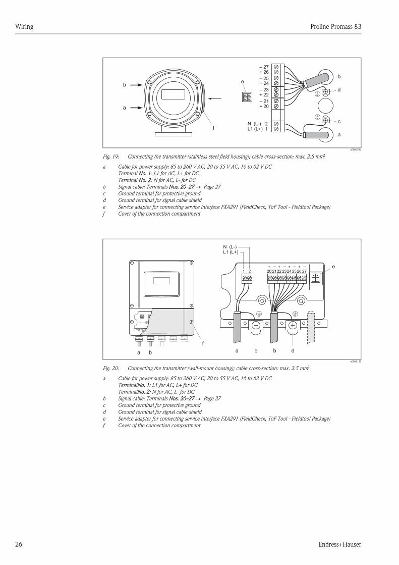
a0004584
Fig. 19: Connecting the transmitter (stainless steel field housing); cable cross-section: max. 2.5 mm2
a Cable for power supply: 85 to 260 V AC, 20 to 55 V AC, 16 to 62 V DC
Terminal No. 1: L1 for AC, L+ for DC
Terminal No. 2: N for AC, L- for DC
b Signal cable: Terminals Nos. 20–27 → Page 27
c Ground terminal for protective ground
d Ground terminal for signal cable shield
e Service adapter for connecting service interface FXA291 (FieldCheck, ToF Tool - Fieldtool Package)
f Cover of the connection compartment
a0001135
Fig. 20: Connecting the transmitter (wall-mount housing); cable cross-section: max. 2.5 mm2
a Cable for power supply: 85 to 260 V AC, 20 to 55 V AC, 16 to 62 V DC
TerminalNo. 1: L1 for AC, L+ for DC
TerminalNo. 2: N for AC, L- for DC
b Signal cable: Terminals Nos. 20–27 → Page 27
c Ground terminal for protective ground
d Ground terminal for signal cable shield
e Service adapter for connecting service interface FXA291 (FieldCheck, ToF Tool - Fieldtool Package)
f Cover of the connection compartment
b
c
d
a
21L1 (L+)
N (L-)f
b
a
e
– 27
– 25
– 23
– 21
+ 26
+ 24
+ 22
+ 20
1 2
c d
e
aa bb
f
+22
–23
+20
–21
+24
–25
+26
–27
L1 (L+)N (L-)
Proline Promass 83 Wiring
Endress+Hauser 27
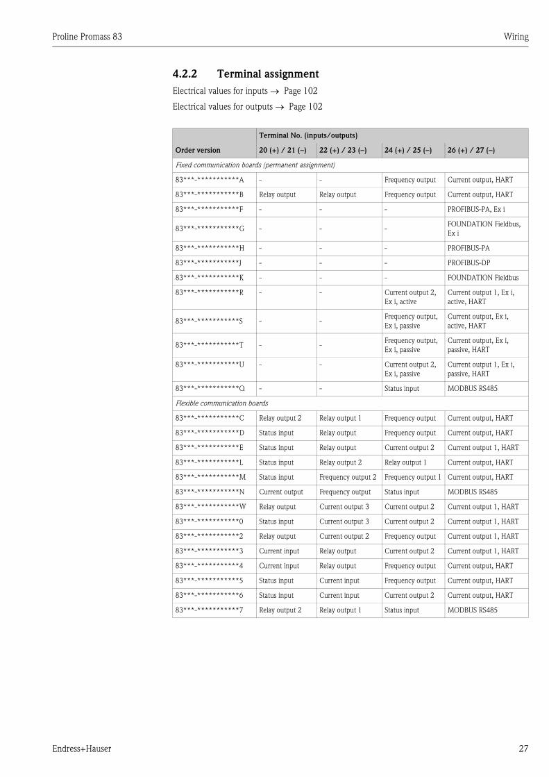
4.2.2 Terminal assignment
Electrical values for inputs → Page 102
Electrical values for outputs → Page 102
Terminal No. (inputs/outputs)
Order version 20 (+) / 21 (–) 22 (+) / 23 (–) 24 (+) / 25 (–) 26 (+) / 27 (–)
Fixed communication boards (permanent assignment)
83***-***********A - - Frequency output Current output, HART
83***-***********B Relay output Relay output Frequency output Current output, HART
83***-***********F - - - PROFIBUS-PA, Ex i
83***-***********G - - -FOUNDATION Fieldbus,
Ex i
83***-***********H - - - PROFIBUS-PA
83***-***********J - - - PROFIBUS-DP
83***-***********K - - - FOUNDATION Fieldbus
83***-***********R - - Current output 2,
Ex i, active
Current output 1, Ex i,
active, HART
83***-***********S - -Frequency output,
Ex i, passive
Current output, Ex i,
active, HART
83***-***********T - -Frequency output,
Ex i, passive
Current output, Ex i,
passive, HART
83***-***********U - - Current output 2,
Ex i, passive
Current output 1, Ex i,
passive, HART
83***-***********Q - - Status input MODBUS RS485
Flexible communication boards
83***-***********C Relay output 2 Relay output 1 Frequency output Current output, HART
83***-***********D Status input Relay output Frequency output Current output, HART
83***-***********E Status input Relay output Current output 2 Current output 1, HART
83***-***********L Status input Relay output 2 Relay output 1 Current output, HART
83***-***********M Status input Frequency output 2 Frequency output 1 Current output, HART
83***-***********N Current output Frequency output Status input MODBUS RS485
83***-***********W Relay output Current output 3 Current output 2 Current output 1, HART
83***-***********0 Status input Current output 3 Current output 2 Current output 1, HART
83***-***********2 Relay output Current output 2 Frequency output Current output 1, HART
83***-***********3 Current input Relay output Current output 2 Current output 1, HART
83***-***********4 Current input Relay output Frequency output Current output, HART
83***-***********5 Status input Current input Frequency output Current output, HART
83***-***********6 Status input Current input Current output 2 Current output, HART
83***-***********7 Relay output 2 Relay output 1 Status input MODBUS RS485
Wiring Proline Promass 83
28 Endress+Hauser
4.2.3 HART connection
Users have the following connection options at their disposal:
• Direct connection to transmitter by means of terminals 26(+) / 27(−)
• Connection by means of the 4 to 20 mA circuit
! Note!
• The measuring circuit's minimum load must be at least 250 Ω.
• The CURRENT SPAN function must be set to "4-20 mA" (individual options see device function).
• See also the documentation issued by the HART Communication Foundation, and in particular
HCF LIT 20: "HART, a technical summary".
Connection of the HART handheld communicator
a0004586
Fig. 21: Electrical connection of HART handheld terminal
1 = HART control unit, 2 = Power supply, 3 = Shielding, 4 = Additional switching units or PLC with passive input
Connection of a PC with an operating software
In order to connect a PC with operating software (e.g. " ToF Tool - Fieldtool Package"), a HART
modem (e.g. "Commubox FXA195") is needed.
a0004592
Fig. 22: Electrical connection of a PC with operating software
1 = PC with operating software, 2 = Power supply, 3 = Shielding,
4 = Additional switching units or PLC with passive input, 5 = HART modem, e.g. Commubox FXA195
+26
³ W250-27
1
34
2
1# % &
Copy
G H I
P Q R S
, ( ) ‘
A B C
Paste
PageOn
PageUp
DeleteBksp
Insert
J K L
T U V
_ < >
D E F
Hot Key
+ Hot Key
M N O
W X Y Z
+ * /
4
7
.
2
5
8
0
375FIELD COMMUNICATOR
3
6
9
-
+26
³ W250
–27
1
2
3
5
4
Proline Promass 83 Wiring
Endress+Hauser 29
4.3 Degree of protection
The measuring device fulfill all the requirements for IP 67.
" Caution!
Do not loosen the screws of the sensor housing, as otherwise the degree of protection guaranteed
by Endress+Hauser no longer applies.
Compliance with the following points is mandatory following installation in the field or servicing,
in order to ensure that IP 67 protection is maintained:
• The housing seals must be clean and undamaged when inserted into their grooves.
The seals must be dried, cleaned or replaced if necessary.
• The threaded fasteners and screw covers must be firmly tightened.
• The cables used for connection must be of the specified outside diameter
→ Page 103, cable entries.
• The cable entries must be firmly tighten (point a → Fig. 23).
• The cable must loop down in front of the cable entry ("water trap") (point b → Fig. 23).
This arrangement prevents moisture penetrating the entry.
The cable entries may not be point up.
• Remove all unused cable entries and insert plugs instead.
• Do not remove the grommet from the cable entry.
a0001914
Fig. 23: Installation instructions, cable entries
a b
Wiring Proline Promass 83
30 Endress+Hauser
4.4 Post-connection check
Perform the following checks after completing electrical installation of the measuring device:
Device condition and specifications Notes
Are cables or the device damaged (visual inspection)? -
Electrical connection Notes
Does the supply voltage match the specifications on the nameplate? 85 to 260 V AC (45 to 65 Hz)
20 to 55 V AC (45 to 65 Hz)
16 to 62 V DC
Do the cables comply with the specifications? → Page 25
Do the cables have adequate strain relief? -
Cables correctly segregated by type?
Without loops and crossovers?
-
Are the power supply and signal cables correctly connected? See the wiring diagram inside
the cover of the terminal
compartment
Are all screw terminals firmly tightened? -
Are all cable entries installed, firmly tightened and correctly sealed?
Cables looped as "water traps"?
→ Page 29
Are all housing covers installed and firmly tightened? -
Proline Promass 83 Operation
Endress+Hauser 31
5 Operation
5.1 Display and operating elements
The local display enables you to read all important parameters directly at the measuring point and
configure the device using the "Quick Setup" or the function matrix.
The display consists of four lines; this is where measured values and/or status variables (direction
of flow, empty pipe, bar graph, etc.) are displayed. You can change the assignment of display lines
to different variables to suit your needs and preferences (→ see the "Description of Device
Functions" manual).
a0001172
Fig. 24: Display and operating elements
1 Liquid crystal display
The backlit, four-line liquid crystal display shows measured values, dialog texts, fault messages and notice
messages. HOME position (operating mode) is the term given to the display during normal operation.
Readings displayed
2 Optical sensors for "Touch Control"
3 Plus/minus keys
– HOME position → Direct access to totalizer values and actual values of inputs/outputs
– Enter numerical values, select parameters
– Select different blocks, groups and function groups within the function matrix
Press the +/− keys (X) simultaneously to trigger the following functions::
– Exit the function matrix step by step → HOME position
– Press and hold down +/− keys for longer than 3 seconds → Return directly to HOME position
– Cancel data entry
4 Enter key
– HOME position → Entry into the function matrix
– Save the numerical values you input or settings you change
+24.502+1863.97
x
y
–50 +50 %
v
v
3S
Esc
E+-
1
2
3 4
xy
+24.502+1863.97
x
y
–50 +50 %
v
v
3S xy
Operation Proline Promass 83
32 Endress+Hauser
5.1.1 Readings displayed (operation mode)
The display area consists of three lines in all; this is where measured values are displayed, and/or
status variables (direction of flow, bar graph, etc.). You can change the assignment of display lines
to different variables to suit your needs and preferences (→ see the "Description of Device
Functions" manual).
Multiplex mode:
A maximum of two different display variables can be assigned to each line. Variables multiplexed in
this way alternate every 10 seconds on the display.
Error messages:
Display and presentation of system/process errors → Page 38
a0001173
Fig. 25: Typical display for normal operating mode (HOME position)
1 Main line: shows main measured values
2 Additional line: shows additional measured variables and status variables
3 Information line: shows additional information on the measured variables and status variables, e.g. bargraph display
4 "Info icons" field: icons representing additional information on the measured values are shown in this field.
→ Page 33
5 "Measured values" field: the current measured values appear in this field.
6 Unit of measure" field: the units of measure and time defined for the current measured values appear in this field.
5.1.2 Additional display functions
Depending on the order option (F-CHIP*), the local display has different display functions.
Device without batching software:
From HOME position, use the OS keys to open an "Info Menu" containing the following
information:
• Totalizer (including overflow)
• Actual values or states of the configured inputs/outputs
• Device TAG number (user-definable)
OS → Scan of individual values within the Info Menu
X (Esc key) → Back to HOME position
Device with batching software:
On measuring instruments with installed batching software (F-Chip*) and a suitably configured
display line, you can carry out filling processes directly using the local display. You will find a
detailed description on → Page 35.
1
4 5 6
2
3
+24.502+1863.97
x
xy
y
–50 +50 %
v
v
3S
*F-CHIP → Page 78
Proline Promass 83 Operation
Endress+Hauser 33
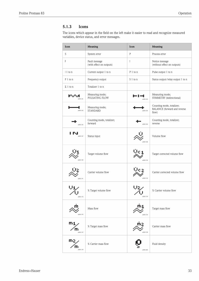
5.1.3 Icons
The icons which appear in the field on the left make it easier to read and recognize measured
variables, device status, and error messages.
Icon Meaning Icon Meaning
S System error P Process error
$ Fault message
(with effect on outputs)
! Notice message
(without effect on outputs)
| 1 to n Current output 1 to n P 1 to n Pulse output 1 to n
F 1 to n Frequency output S 1 to n Status output/relay output 1 to n
Σ 1 to n Totalizer 1 to n
a0001181
Measuring mode;
PULSATING FLOWa0001182
Measuring mode;
SYMMETRY (bidirectional)
a0001183
Measuring mode;
STANDARD a0001184
Counting mode, totalizer;
BALANCE (forward and reverse
flow)
a0001185
Counting mode, totalizer;
forward a0001186
Counting mode, totalizer;
reverse
a0001187 Status input
a0001188
Volume flow
a0001189
Target volume flow
a0001190
Target corrected volume flow
a0001191
Carrier volume flow
a0001192
Carrier corrected volume flow
a0001193
% Target volume flow
a0001194
% Carrier volume flow
a0001195
Mass flow
a0001196
Target mass flow
a0001197
% Target mass flow
a0001198
Carrier mass flow
a0001199
% Carrier mass flow
a0001200
Fluid density
Operation Proline Promass 83
34 Endress+Hauser
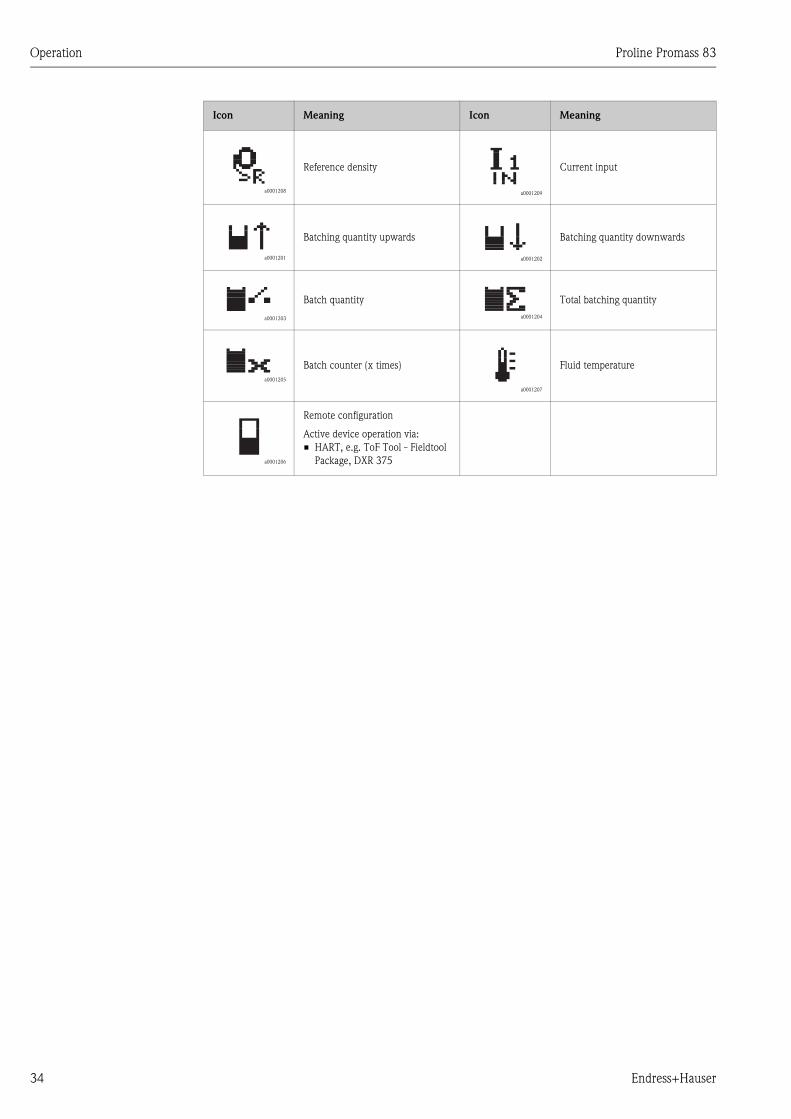
a0001208
Reference density
a0001209
Current input
a0001201
Batching quantity upwards
a0001202
Batching quantity downwards
a0001203
Batch quantity
a0001204
Total batching quantity
a0001205
Batch counter (x times)
a0001207
Fluid temperature
a0001206
Remote configuration
Active device operation via:
• HART, e.g. ToF Tool - Fieldtool
Package, DXR 375
Icon Meaning Icon Meaning
Proline Promass 83 Operation
Endress+Hauser 35
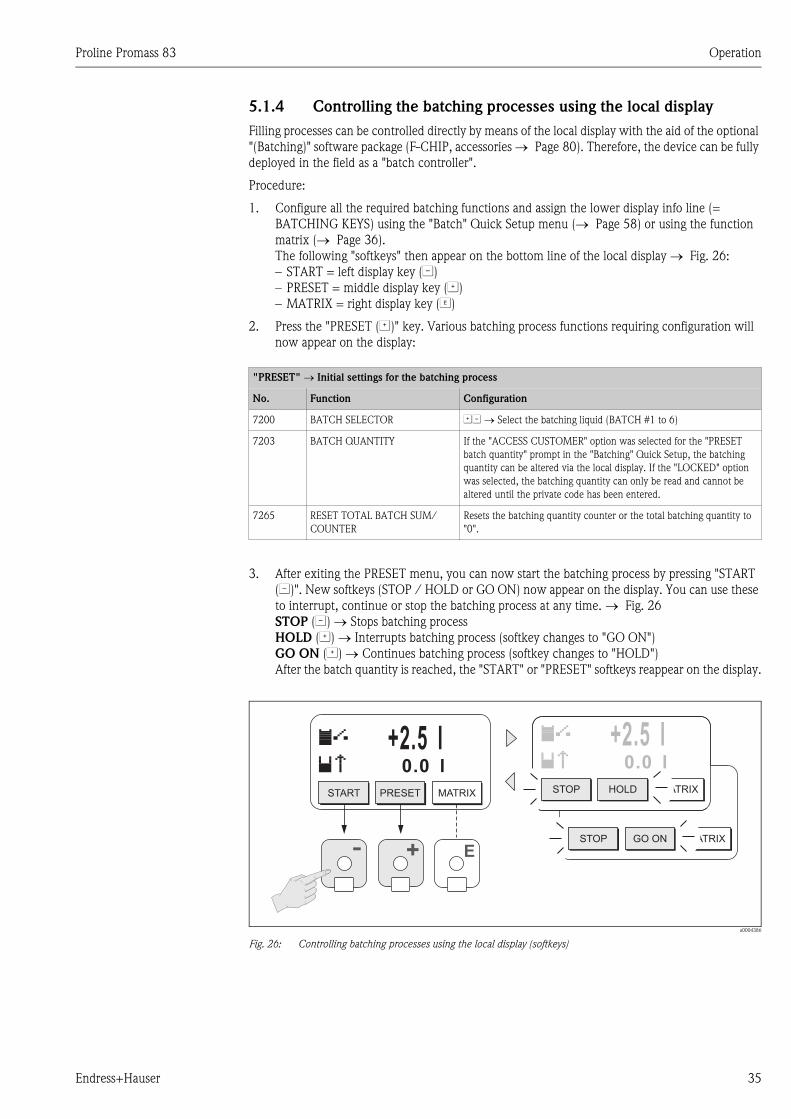
5.1.4 Controlling the batching processes using the local display
Filling processes can be controlled directly by means of the local display with the aid of the optional
"(Batching)" software package (F-CHIP, accessories → Page 80). Therefore, the device can be fully
deployed in the field as a "batch controller".
Procedure:
1. Configure all the required batching functions and assign the lower display info line (=
BATCHING KEYS) using the "Batch" Quick Setup menu (→ Page 58) or using the function
matrix (→ Page 36).
The following "softkeys" then appear on the bottom line of the local display → Fig. 26:
– START = left display key (S)
– PRESET = middle display key (O)
– MATRIX = right display key (F)
2. Press the "PRESET (O)" key. Various batching process functions requiring configuration will
now appear on the display:
3. After exiting the PRESET menu, you can now start the batching process by pressing "START
(S)". New softkeys (STOP / HOLD or GO ON) now appear on the display. You can use these
to interrupt, continue or stop the batching process at any time. → Fig. 26
STOP (S) → Stops batching process
HOLD (O) → Interrupts batching process (softkey changes to "GO ON")
GO ON (O) → Continues batching process (softkey changes to "HOLD")
After the batch quantity is reached, the "START" or "PRESET" softkeys reappear on the display.
a0004386
Fig. 26: Controlling batching processes using the local display (softkeys)
"PRESET" → Initial settings for the batching process
No. Function Configuration
7200 BATCH SELECTOR OS → Select the batching liquid (BATCH #1 to 6)
7203 BATCH QUANTITY If the "ACCESS CUSTOMER" option was selected for the "PRESET
batch quantity" prompt in the "Batching" Quick Setup, the batching
quantity can be altered via the local display. If the "LOCKED" option
was selected, the batching quantity can only be read and cannot be
altered until the private code has been entered.
7265 RESET TOTAL BATCH SUM/
COUNTER
Resets the batching quantity counter or the total batching quantity to
"0".
STOP GO ON MATRIX
+2.5 l0.0 l
+2.5 l0.0 l0.0 l
+-
+2.5 l0.0 l
START PRESET MATRIX STOP HOLD MATRIX
E
Operation Proline Promass 83
36 Endress+Hauser
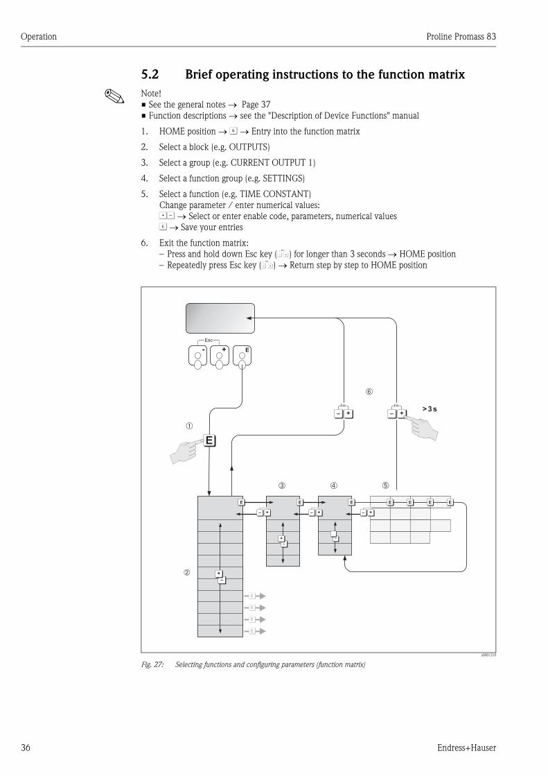
5.2 Brief operating instructions to the function matrix
! Note!
• See the general notes → Page 37
• Function descriptions → see the "Description of Device Functions" manual
1. HOME position → F → Entry into the function matrix
2. Select a block (e.g. OUTPUTS)
3. Select a group (e.g. CURRENT OUTPUT 1)
4. Select a function group (e.g. SETTINGS)
5. Select a function (e.g. TIME CONSTANT)
Change parameter / enter numerical values:
OS → Select or enter enable code, parameters, numerical values
F → Save your entries
6. Exit the function matrix:
– Press and hold down Esc key (X) for longer than 3 seconds → HOME position
– Repeatedly press Esc key (X) → Return step by step to HOME position
a0001210
Fig. 27: Selecting functions and configuring parameters (function matrix)
- + E
Esc
>3s
E
E
E
E
E E E E E E E
–
+
–
+ –
E
+
Esc
–
+– +– +–
+
Esc
–
➀
➂ ➃ ➄
➅
➁
Proline Promass 83 Operation
Endress+Hauser 37
5.2.1 General notes
The Quick Setup menu contains the default settings that are adequate for commissioning. Complex
measuring operations on the other hand necessitate additional functions that you can configure as
necessary and customize to suit your process parameters. The function matrix, therefore, comprises
a multiplicity of additional functions which, for the sake of clarity, are arranged on a number of
menu levels (blocks, groups, and function groups).
Comply with the following instructions when configuring functions:
• You select functions as described on → Page 36.
Each cell in the function matrix is identified by a numerical or letter code on the display.
• You can switch off certain functions (OFF). If you do so, related functions in other function groups
will no longer be displayed.
• Certain functions prompt you to confirm your data entries. Press OS to select "SURE [ YES ]" and
press F to confirm. This saves your setting or starts a function, as applicable.
• Return to the HOME position is automatic if no key is pressed for 5 minutes.
• Programming mode is disabled automatically if you do not press a key within 60 seconds
following automatic return to the HOME position.
" Caution!
All functions are described in detail, as is the function matrix itself, in the "Description of Device
Functions" manual, which is a separate part of these Operating Instructions.
! Note!
• The transmitter continues to measure while data entry is in progress, i.e. the current measured
values are output via the signal outputs in the normal way.
• If the supply voltage fails all preset and parameterized values remain safely stored in the EEPROM.
5.2.2 Enabling the programming mode
The function matrix can be disabled. Disabling the function matrix rules out the possibility of
inadvertent changes to device functions, numerical values or factory settings. A numerical code
(factory setting = 83) has to be entered before settings can be changed.
If you use a code number of your choice, you exclude the possibility of unauthorized persons
accessing data (→ see the "Description of Device Functions" manual).
Comply with the following instructions when entering codes:
• If programming is disabled and the P operating elements are pressed in any function, a prompt
for the code automatically appears on the display.
• If "0" is entered as the customer's code, programming is always enabled!
• The Endress+Hauser service organization can be of assistance if you mislay your personal code.
" Caution!
Changing certain parameters such as all sensor characteristics, for example, influences numerous
functions of the entire measuring system, particularly measuring accuracy.
There is no need to change these parameters under normal circumstances and consequently, they
are protected by a special code known only to the Endress+Hauser service organization. Please
contact Endress+Hauser if you have any questions.
5.2.3 Disabling the programming mode
Programming mode is disabled if you do not press an operating element within 60 seconds following
automatic return to the HOME position.
You can also disable programming in the ACCESS CODE function by entering any number (other
than the customer's code).
Operation Proline Promass 83
38 Endress+Hauser
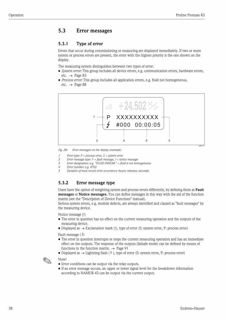
5.3 Error messages
5.3.1 Type of error
Errors that occur during commissioning or measuring are displayed immediately. If two or more
system or process errors are present, the error with the highest priority is the one shown on the
display.
The measuring system distinguishes between two types of error:
• System error: This group includes all device errors, e.g. communication errors, hardware errors,
etc. → Page 83
• Process error: This group includes all application errors, e.g. fluid not homogeneous,
etc. → Page 88
a0001211
Fig. 28: Error messages on the display (example)
1 Error type: P = process error, S = system error
2 Error message type: $ = fault message, ! = notice message
3 Error designation: e.g. "FLUID INHOM." = fluid is not homogeneous
4 Error number: e.g. #702
5 Duration of most recent error occurrence (hours: minutes: seconds)
5.3.2 Error message type
Users have the option of weighting system and process errors differently, by defining them as Fault
messages or Notice messages. You can define messages in this way with the aid of the function
matrix (see the "Description of Device Functions" manual).
Serious system errors, e.g. module defects, are always identified and classed as "fault messages" by
the measuring device.
Notice message (!)
• The error in question has no effect on the current measuring operation and the outputs of the
measuring device.
• Displayed as → Exclamation mark (!), type of error (S: system error, P: process error)
Fault message ( $)• The error in question interrupts or stops the current measuring operation and has an immediate
effect on the outputs. The response of the outputs (failsafe mode) can be defined by means of
functions in the function matrix. → Page 91
• Displayed as → Lightning flash ( $ ), type of error (S: system error, P: process error)
! Note!
• Error conditions can be output via the relay outputs.
• If an error message occurs, an upper or lower signal level for the breakdown information
according to NAMUR 43 can be output via the current output.
1
2 4 5 3
+24.502XXXXXXXXXX#000 00:00:05
P
+24.502
Proline Promass 83 Operation
Endress+Hauser 39
5.3.3 Confirming error messages
For the sake of plant and process safety, the measuring device can be configured in such a way that
fault messages displayed ($) always have to be rectified and acknowledged locally by pressing F.
Only then do the error messages disappear from the display.
This option can be switched on or off by means of the "ACKNOWLEDGE FAULT MESSAGES"
function (see the "Description of Device Functions" manual).
! Note!
• Fault messages ($) can also be reset and confirmed via the status input.
• Notice messages (!) do not require acknowledgment. Note, however, that they remain visible
until the cause of the error has been rectified.
5.4 Communication
In addition to local operation, the measuring device can be configured and measured values can be
obtained by means of the HART protocol. Digital communication takes place using the 4-20 mA
current output HART. → Page 28
The HART protocol allows the transfer of measuring and device data between the HART master and
the field devices for configuration and diagnostics purposes. The HART master, e.g. a handheld
terminal or PC-based operating programs (such as ToF Tool - Fieldtool Package, FieldCare), require
device description (DD) files which are used to access all the information in a HART device.
Information is exclusively transferred using so-called "commands". There are three different
command groups:
There are three different command groups:
• Universal Commands
Universal commands are supported and used by all HART devices. These are associated with the
following functionalities for example:
– Recognizing HART devices
– Reading digital measured values (volume flow, totalizer, etc.)
• Common practice commands:
Common practice commands offer functions which are supported and can be executed by most
but not all field devices.
• Device-specific commands:
These commands allow access to device-specific functions which are not HART standard. Such
commands access individual field device information, amongst other things, such as empty/full
pipe calibration values, low flow cutoff settings, etc.
! Note!
The measuring device has access to all three command classes.
List of all "Universal Commands" and "Common Practice Commands": → Page 43
Operation Proline Promass 83
40 Endress+Hauser
5.4.1 Operating options
For the complete operation of the measuring device, including device-specific commands, there are
DD files available to the user to provide the following operating aids and programs:
! Note!
• In the CURRENT RANGE function (current output 1), the HART protocol demands the setting
"4-20 mA HART" or "4-20 mA (25 mA) HART".
• HART write protection can be disabled or enabled by means of a jumper on the I/O board.
→ Page 51
HART handheld terminal DXR 375
Selecting device functions with a HART Communicator is a process involving a number of menu
levels and a special HART function matrix.
The HART manual in the carrying case of the HART Communicator contains more detailed
information on the device.
Operating program "ToF Tool - Fieldtool Package"
Modular software package consisting of the service program "ToF Tool" for configuration and
diagnosis of ToF level measuring devices (time-of-flight measurement) and evolution of pressure
measuring instruments as well as the "Fieldtool" service program for the configuration and diagnosis
of Proline flowmeters.
The Proline flowmeters are accessed via a service interface or via the service interface FXA291 or
the HART protocol.
Contents of the "ToF Tool - Fieldtool Package":
• Commissioning, maintenance analysis
• Configuring flowmeters
• Service functions
• Visualization of process data
• Troubleshooting
• Reading out the verification data and updating the software of the "Fieldcheck" flow simulator
FieldCare
FieldCare is Endress+Hauser’s FDT-based plant asset management tool and allows the configuration
and diagnosis of intelligent field devices. By using status information, you also have a simple but
effective tool for monitoring devices. The Proline flowmeters are accessed via a service interface or
via the service interface FXA291.
Operating program "SIMATIC PDM" (Siemens)
SIMATIC PDM is a standardized, manufacturer-independent tool for the operation, configuration,
maintenance and diagnosis of intelligent field devices.
Operating program "AMS" (Emerson Process Management)
AMS (Asset Management Solutions): program for operating and configuring devices
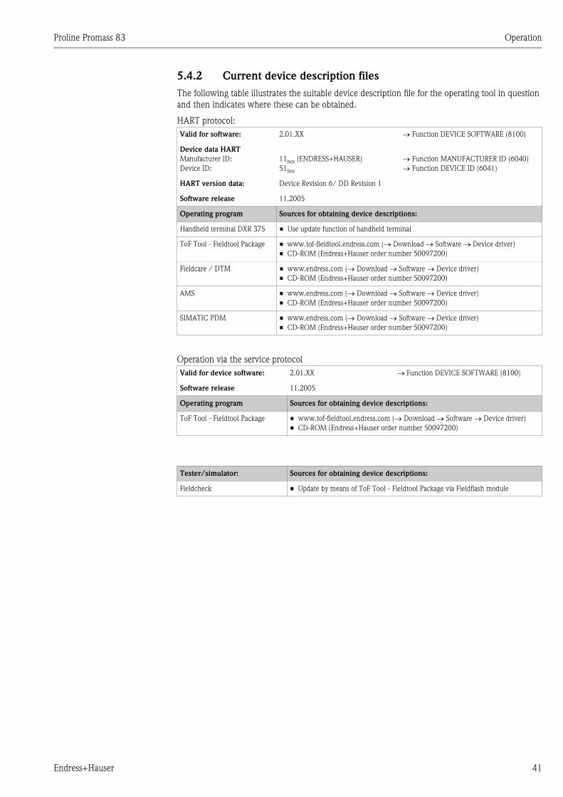
Proline Promass 83 Operation
Endress+Hauser 41
5.4.2 Current device description files
The following table illustrates the suitable device description file for the operating tool in question
and then indicates where these can be obtained.
HART protocol:
Operation via the service protocol
Valid for software: 2.01.XX → Function DEVICE SOFTWARE (8100)
Device data HART
Manufacturer ID:
Device ID:
11hex (ENDRESS+HAUSER)
51hex
→ Function MANUFACTURER ID (6040)
→ Function DEVICE ID (6041)
HART version data: Device Revision 6/ DD Revision 1
Software release 11.2005
Operating program Sources for obtaining device descriptions:
Handheld terminal DXR 375 • Use update function of handheld terminal
ToF Tool - Fieldtool Package • www.tof-fieldtool.endress.com (→ Download → Software → Device driver)
• CD-ROM (Endress+Hauser order number 50097200)
Fieldcare / DTM • www.endress.com (→ Download → Software → Device driver)
• CD-ROM (Endress+Hauser order number 50097200)
AMS • www.endress.com (→ Download → Software → Device driver)
• CD-ROM (Endress+Hauser order number 50097200)
SIMATIC PDM • www.endress.com (→ Download → Software → Device driver)
• CD-ROM (Endress+Hauser order number 50097200)
Valid for device software: 2.01.XX → Function DEVICE SOFTWARE (8100)
Software release 11.2005
Operating program Sources for obtaining device descriptions:
ToF Tool - Fieldtool Package • www.tof-fieldtool.endress.com (→ Download → Software → Device driver)
• CD-ROM (Endress+Hauser order number 50097200)
Tester/simulator: Sources for obtaining device descriptions:
Fieldcheck • Update by means of ToF Tool - Fieldtool Package via Fieldflash module
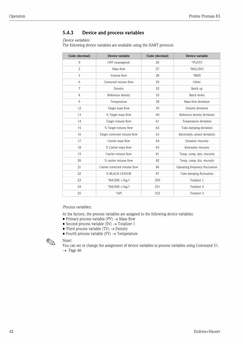
Operation Proline Promass 83
42 Endress+Hauser
5.4.3 Device and process variables
Device variables:
The following device variables are available using the HART protocol:
Process variables:
At the factory, the process variables are assigned to the following device variables:
• Primary process variable (PV) → Mass flow
• Second process variable (SV) → Totalizer 1
• Third process variable (TV) → Density
• Fourth process variable (FV) → Temperature
! Note!
You can set or change the assignment of device variables to process variables using Command 51.
→ Page 46
Code (decimal) Device variable Code (decimal) Device variable
0 OFF (unassigned) 26 °PLATO
2 Mass flow 27 °BALLING
5 Volume flow 28 °BRIX
6 Corrected volume flow 29 Other
7 Density 52 Batch up
8 Reference density 53 Batch down
9 Temperature 58 Mass flow deviation
12 Target mass flow 59 Density deviation
13 % Target mass flow 60 Reference density deviation
14 Target volume flow 61 Temperature deviation
15 % Target volume flow 62 Tube damping deviation
16 Target corrected volume flow 63 Electrodyn. sensor deviation
17 Carrier mass flow 64 Dynamic viscosity
18 % Carrier mass flow 65 Kinematic viscosity
19 Carrier volume flow 81 Temp. comp. dyn. viscosity
20 % carrier volume flow 82 Temp. comp. kin. viscosity
21 Carrier corrected volume flow 86 Operating frequency fluctuation
22 %-BLACK LIQUOR 87 Tube damping fluctuation
23 °BAUME >1kg/l 250 Totalizer 1
24 °BAUME <1kg/l 251 Totalizer 2
25 °API 252 Totalizer 3
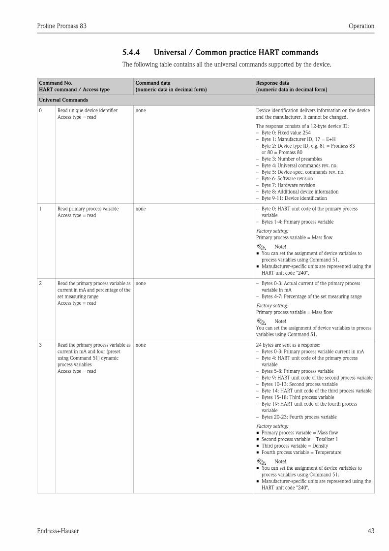
Proline Promass 83 Operation
Endress+Hauser 43
5.4.4 Universal / Common practice HART commands
The following table contains all the universal commands supported by the device.
Command No.
HART command / Access type
Command data
(numeric data in decimal form)
Response data
(numeric data in decimal form)
Universal Commands
0 Read unique device identifier
Access type = read
none Device identification delivers information on the device
and the manufacturer. It cannot be changed.
The response consists of a 12-byte device ID:
– Byte 0: Fixed value 254
– Byte 1: Manufacturer ID, 17 = E+H
– Byte 2: Device type ID, e.g. 81 = Promass 83
or 80 = Promass 80
– Byte 3: Number of preambles
– Byte 4: Universal commands rev. no.
– Byte 5: Device-spec. commands rev. no.
– Byte 6: Software revision
– Byte 7: Hardware revision
– Byte 8: Additional device information
– Byte 9-11: Device identification
1 Read primary process variable
Access type = read
none – Byte 0: HART unit code of the primary process
variable
– Bytes 1-4: Primary process variable
Factory setting:
Primary process variable = Mass flow
! Note!
• You can set the assignment of device variables to
process variables using Command 51.
• Manufacturer-specific units are represented using the
HART unit code "240".
2 Read the primary process variable as
current in mA and percentage of the
set measuring range
Access type = read
none – Bytes 0-3: Actual current of the primary process
variable in mA
– Bytes 4-7: Percentage of the set measuring range
Factory setting:
Primary process variable = Mass flow
! Note!
You can set the assignment of device variables to process
variables using Command 51.
3 Read the primary process variable as
current in mA and four (preset
using Command 51) dynamic
process variables
Access type = read
none 24 bytes are sent as a response:
– Bytes 0-3: Primary process variable current in mA
– Byte 4: HART unit code of the primary process
variable
– Bytes 5-8: Primary process variable
– Byte 9: HART unit code of the second process variable
– Bytes 10-13: Second process variable
– Byte 14: HART unit code of the third process variable
– Bytes 15-18: Third process variable
– Byte 19: HART unit code of the fourth process
variable
– Bytes 20-23: Fourth process variable
Factory setting:
• Primary process variable = Mass flow
• Second process variable = Totalizer 1
• Third process variable = Density
• Fourth process variable = Temperature
! Note!
• You can set the assignment of device variables to
process variables using Command 51.
• Manufacturer-specific units are represented using the
HART unit code "240".
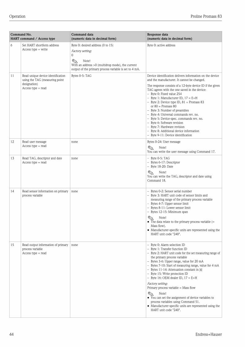
Operation Proline Promass 83
44 Endress+Hauser
6 Set HART shortform address
Access type = write
Byte 0: desired address (0 to 15)
Factory setting:
0
! Note!
With an address >0 (multidrop mode), the current
output of the primary process variable is set to 4 mA.
Byte 0: active address
11 Read unique device identification
using the TAG (measuring point
designation)
Access type = read
Bytes 0-5: TAG Device identification delivers information on the device
and the manufacturer. It cannot be changed.
The response consists of a 12-byte device ID if the given
TAG agrees with the one saved in the device:
– Byte 0: Fixed value 254
– Byte 1: Manufacturer ID, 17 = E+H
– Byte 2: Device type ID, 81 = Promass 83
or 80 = Promass 80
– Byte 3: Number of preambles
– Byte 4: Universal commands rev. no.
– Byte 5: Device-spec. commands rev. no.
– Byte 6: Software revision
– Byte 7: Hardware revision
– Byte 8: Additional device information
– Byte 9-11: Device identification
12 Read user message
Access type = read
none Bytes 0-24: User message
! Note!
You can write the user message using Command 17.
13 Read TAG, descriptor and date
Access type = read
none – Byte 0-5: TAG
– Bytes 6-17: Descriptor
– Byte 18-20: Date
! Note!
You can write the TAG, descriptor and date using
Command 18.
14 Read sensor information on primary
process variable
none – Bytes 0-2: Sensor serial number
– Byte 3: HART unit code of sensor limits and
measuring range of the primary process variable
– Bytes 4-7: Upper sensor limit
– Bytes 8-11: Lower sensor limit
– Bytes 12-15: Minimum span
! Note!
• The data relate to the primary process variable (=
Mass flow).
• Manufacturer-specific units are represented using the
HART unit code "240".
15 Read output information of primary
process variable
Access type = read
none – Byte 0: Alarm selection ID
– Byte 1: Transfer function ID
– Byte 2: HART unit code for the set measuring range of
the primary process variable
– Bytes 3-6: Upper range, value for 20 mA
– Bytes 7-10: Start of measuring range, value for 4 mA
– Bytes 11-14: Attenuation constant in [s]
– Byte 15: Write protection ID
– Byte 16: OEM dealer ID, 17 = E+H
Factory setting:
Primary process variable = Mass flow
! Note!
• You can set the assignment of device variables to
process variables using Command 51.
• Manufacturer-specific units are represented using the
HART unit code "240".
Command No.
HART command / Access type
Command data
(numeric data in decimal form)
Response data
(numeric data in decimal form)
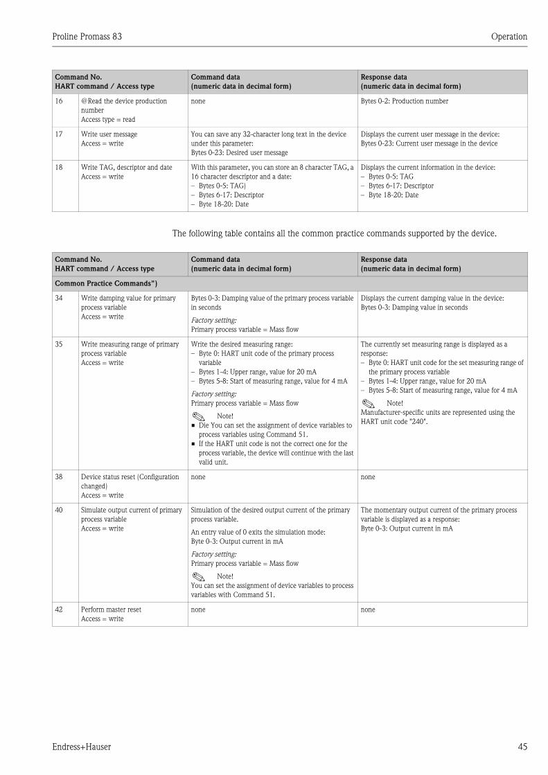
Proline Promass 83 Operation
Endress+Hauser 45
The following table contains all the common practice commands supported by the device.
16 @Read the device production
number
Access type = read
none Bytes 0-2: Production number
17 Write user message
Access = write
You can save any 32-character long text in the device
under this parameter:
Bytes 0-23: Desired user message
Displays the current user message in the device:
Bytes 0-23: Current user message in the device
18 Write TAG, descriptor and date
Access = write
With this parameter, you can store an 8 character TAG, a
16 character descriptor and a date:
– Bytes 0-5: TAG)
– Bytes 6-17: Descriptor
– Byte 18-20: Date
Displays the current information in the device:
– Bytes 0-5: TAG
– Bytes 6-17: Descriptor
– Byte 18-20: Date
Command No.
HART command / Access type
Command data
(numeric data in decimal form)
Response data
(numeric data in decimal form)
Command No.
HART command / Access type
Command data
(numeric data in decimal form)
Response data
(numeric data in decimal form)
Common Practice Commands")
34 Write damping value for primary
process variable
Access = write
Bytes 0-3: Damping value of the primary process variable
in seconds
Factory setting:
Primary process variable = Mass flow
Displays the current damping value in the device:
Bytes 0-3: Damping value in seconds
35 Write measuring range of primary
process variable
Access = write
Write the desired measuring range:
– Byte 0: HART unit code of the primary process
variable
– Bytes 1-4: Upper range, value for 20 mA
– Bytes 5-8: Start of measuring range, value for 4 mA
Factory setting:
Primary process variable = Mass flow
! Note!
• Die You can set the assignment of device variables to
process variables using Command 51.
• If the HART unit code is not the correct one for the
process variable, the device will continue with the last
valid unit.
The currently set measuring range is displayed as a
response:
– Byte 0: HART unit code for the set measuring range of
the primary process variable
– Bytes 1-4: Upper range, value for 20 mA
– Bytes 5-8: Start of measuring range, value for 4 mA
! Note!
Manufacturer-specific units are represented using the
HART unit code "240".
38 Device status reset (Configuration
changed)
Access = write
none none
40 Simulate output current of primary
process variable
Access = write
Simulation of the desired output current of the primary
process variable.
An entry value of 0 exits the simulation mode:
Byte 0-3: Output current in mA
Factory setting:
Primary process variable = Mass flow
! Note!
You can set the assignment of device variables to process
variables with Command 51.
The momentary output current of the primary process
variable is displayed as a response:
Byte 0-3: Output current in mA
42 Perform master reset
Access = write
none none
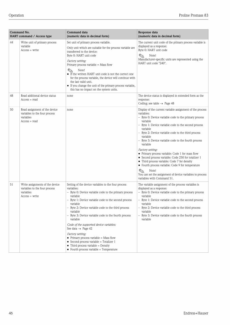
Operation Proline Promass 83
46 Endress+Hauser
44 Write unit of primary process
variable
Access = write
Set unit of primary process variable.
Only unit which are suitable for the process variable are
transferred to the device:
Byte 0: HART unit code
Factory setting:
Primary process variable = Mass flow
! Note!
• If the written HART unit code is not the correct one
for the process variable, the device will continue with
the last valid unit.
• If you change the unit of the primary process variable,
this has no impact on the system units.
The current unit code of the primary process variable is
displayed as a response:
Byte 0: HART unit code
! Note!
Manufacturer-specific units are represented using the
HART unit code "240".
48 Read additional device status
Access = read
none The device status is displayed in extended form as the
response:
Coding: see table → Page 48
50 Read assignment of the device
variables to the four process
variables
Access = read
none Display of the current variable assignment of the process
variables:
– Byte 0: Device variable code to the primary process
variable
– Byte 1: Device variable code to the second process
variable
– Byte 2: Device variable code to the third process
variable
– Byte 3: Device variable code to the fourth process
variable
Factory setting:
• Primary process variable: Code 1 for mass flow
• Second process variable: Code 250 for totalizer 1
• Third process variable: Code 7 for density
• Fourth process variable: Code 9 for temperature
! Note!
You can set the assignment of device variables to process
variables with Command 51.
51 Write assignments of the device
variables to the four process
variables
Access = write
Setting of the device variables to the four process
variables:
– Byte 0: Device variable code to the primary process
variable
– Byte 1: Device variable code to the second process
variable
– Byte 2: Device variable code to the third process
variable
– Byte 3: Device variable code to the fourth process
variable
Code of the supported device variables:
See data → Page 42
Factory setting:
• Primary process variable = Mass flow
• Second process variable = Totalizer 1
• Third process variable = Density
• Fourth process variable = Temperature
The variable assignment of the process variables is
displayed as a response:
– Byte 0: Device variable code to the primary process
variable
– Byte 1: Device variable code to the second process
variable
– Byte 2: Device variable code to the third process
variable
– Byte 3: Device variable code to the fourth process
variable
Command No.
HART command / Access type
Command data
(numeric data in decimal form)
Response data
(numeric data in decimal form)
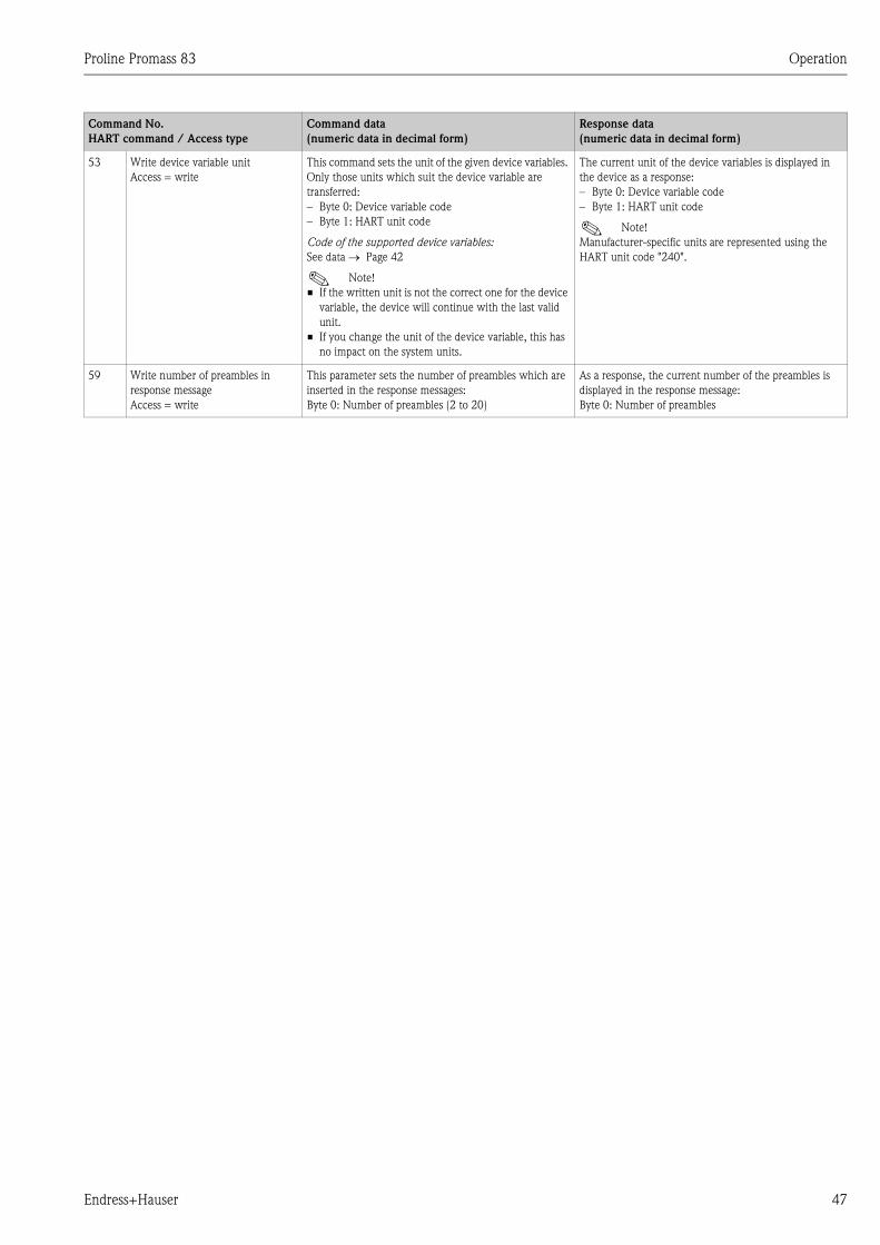
Proline Promass 83 Operation
Endress+Hauser 47
53 Write device variable unit
Access = write
This command sets the unit of the given device variables.
Only those units which suit the device variable are
transferred:
– Byte 0: Device variable code
– Byte 1: HART unit code
Code of the supported device variables:
See data → Page 42
! Note!
• If the written unit is not the correct one for the device
variable, the device will continue with the last valid
unit.
• If you change the unit of the device variable, this has
no impact on the system units.
The current unit of the device variables is displayed in
the device as a response:
– Byte 0: Device variable code
– Byte 1: HART unit code
! Note!
Manufacturer-specific units are represented using the
HART unit code "240".
59 Write number of preambles in
response message
Access = write
This parameter sets the number of preambles which are
inserted in the response messages:
Byte 0: Number of preambles (2 to 20)
As a response, the current number of the preambles is
displayed in the response message:
Byte 0: Number of preambles
Command No.
HART command / Access type
Command data
(numeric data in decimal form)
Response data
(numeric data in decimal form)
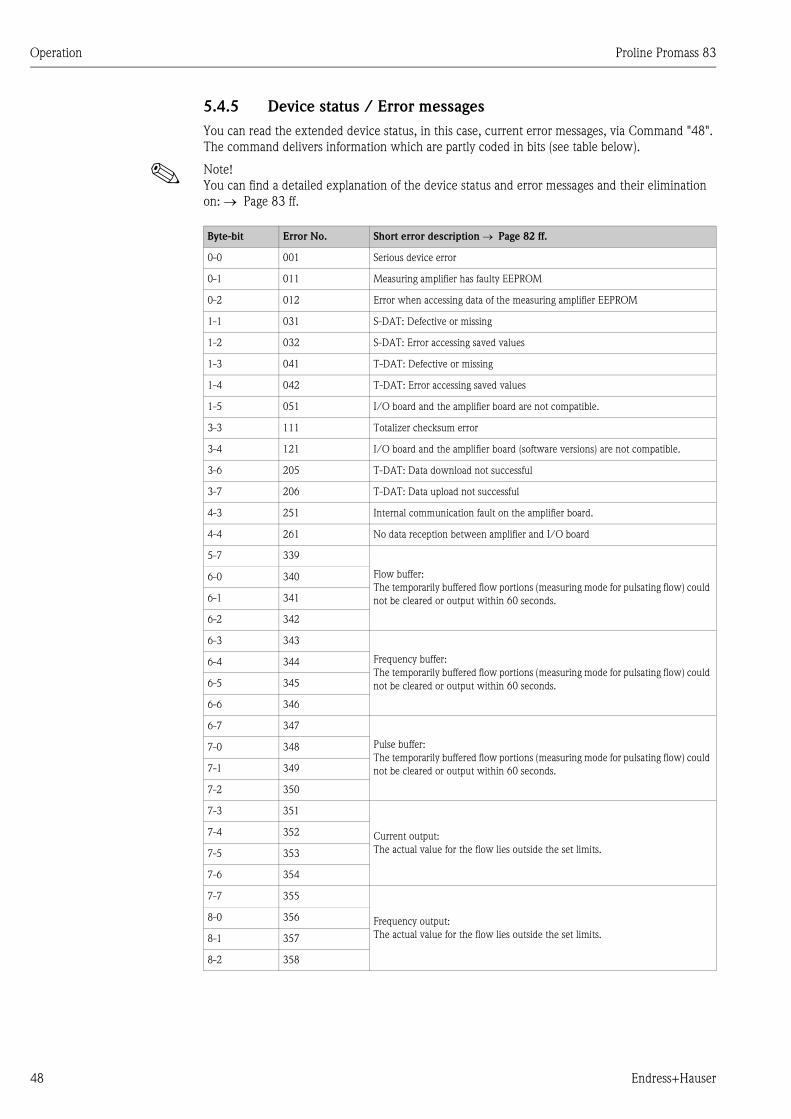
Operation Proline Promass 83
48 Endress+Hauser
5.4.5 Device status / Error messages
You can read the extended device status, in this case, current error messages, via Command "48".
The command delivers information which are partly coded in bits (see table below).
! Note!
You can find a detailed explanation of the device status and error messages and their elimination
on: → Page 83 ff.
Byte-bit Error No. Short error description → Page 82 ff.
0-0 001 Serious device error
0-1 011 Measuring amplifier has faulty EEPROM
0-2 012 Error when accessing data of the measuring amplifier EEPROM
1-1 031 S-DAT: Defective or missing
1-2 032 S-DAT: Error accessing saved values
1-3 041 T-DAT: Defective or missing
1-4 042 T-DAT: Error accessing saved values
1-5 051 I/O board and the amplifier board are not compatible.
3-3 111 Totalizer checksum error
3-4 121 I/O board and the amplifier board (software versions) are not compatible.
3-6 205 T-DAT: Data download not successful
3-7 206 T-DAT: Data upload not successful
4-3 251 Internal communication fault on the amplifier board.
4-4 261 No data reception between amplifier and I/O board
5-7 339
Flow buffer:
The temporarily buffered flow portions (measuring mode for pulsating flow) could
not be cleared or output within 60 seconds.
6-0 340
6-1 341
6-2 342
6-3 343
Frequency buffer:
The temporarily buffered flow portions (measuring mode for pulsating flow) could
not be cleared or output within 60 seconds.
6-4 344
6-5 345
6-6 346
6-7 347
Pulse buffer:
The temporarily buffered flow portions (measuring mode for pulsating flow) could
not be cleared or output within 60 seconds.
7-0 348
7-1 349
7-2 350
7-3 351
Current output:
The actual value for the flow lies outside the set limits.
7-4 352
7-5 353
7-6 354
7-7 355
Frequency output:
The actual value for the flow lies outside the set limits.
8-0 356
8-1 357
8-2 358
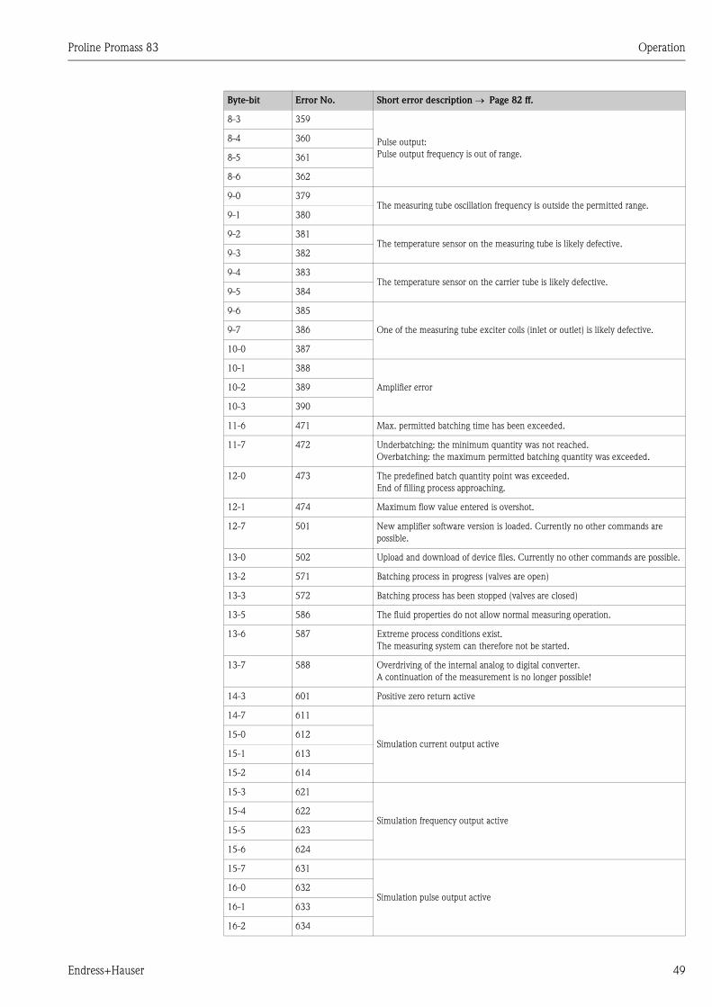
Proline Promass 83 Operation
Endress+Hauser 49
8-3 359
Pulse output:
Pulse output frequency is out of range.
8-4 360
8-5 361
8-6 362
9-0 379The measuring tube oscillation frequency is outside the permitted range.
9-1 380
9-2 381The temperature sensor on the measuring tube is likely defective.
9-3 382
9-4 383The temperature sensor on the carrier tube is likely defective.
9-5 384
9-6 385
One of the measuring tube exciter coils (inlet or outlet) is likely defective.9-7 386
10-0 387
10-1 388
Amplifier error10-2 389
10-3 390
11-6 471 Max. permitted batching time has been exceeded.
11-7 472 Underbatching: the minimum quantity was not reached.
Overbatching: the maximum permitted batching quantity was exceeded.
12-0 473 The predefined batch quantity point was exceeded.
End of filling process approaching.
12-1 474 Maximum flow value entered is overshot.
12-7 501 New amplifier software version is loaded. Currently no other commands are
possible.
13-0 502 Upload and download of device files. Currently no other commands are possible.
13-2 571 Batching process in progress (valves are open)
13-3 572 Batching process has been stopped (valves are closed)
13-5 586 The fluid properties do not allow normal measuring operation.
13-6 587 Extreme process conditions exist.
The measuring system can therefore not be started.
13-7 588 Overdriving of the internal analog to digital converter.
A continuation of the measurement is no longer possible!
14-3 601 Positive zero return active
14-7 611
Simulation current output active15-0 612
15-1 613
15-2 614
15-3 621
Simulation frequency output active15-4 622
15-5 623
15-6 624
15-7 631
Simulation pulse output active16-0 632
16-1 633
16-2 634
Byte-bit Error No. Short error description → Page 82 ff.
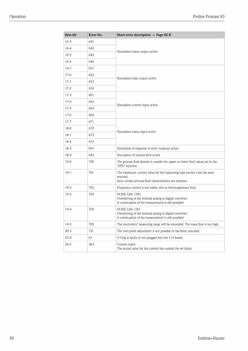
Operation Proline Promass 83
50 Endress+Hauser
16-3 641
Simulation status output active16-4 642
16-5 643
16-6 644
16-7 651
Simulation relay output active17-0 652
17-1 653
17-2 654
17-3 661
Simulation current input active17-4 662
17-5 663
17-6 664
17-7 671
Simulation status input active18-0 672
18-1 673
18-2 674
18-3 691 Simulation of response to error (outputs) active
18-4 692 Simulation of volume flow active
19-0 700 The process fluid density is outside the upper or lower limit values set in the
"EPD" function
19-1 701 The maximum current value for the measuring tube exciter coils has been
reached,
since certain process fluid characteristics are extreme.
19-2 702 Frequency control is not stable, due to inhomogeneous fluid.
19-3 703 NOISE LIM. CH0
Overdriving of the internal analog to digital converter.
A continuation of the measurement is still possible!
19-4 704 NOISE LIM. CH1
Overdriving of the internal analog to digital converter.
A continuation of the measurement is still possible!
19-5 705 The electronics' measuring range will be exceeded. The mass flow is too high.
20-5 731 The zero point adjustment is not possible or has been canceled.
22-4 61 F-Chip is faulty or not plugged into the I/O board.
24-5 363 Current input:
The actual value for the current lies outside the set limits.
Byte-bit Error No. Short error description → Page 82 ff.
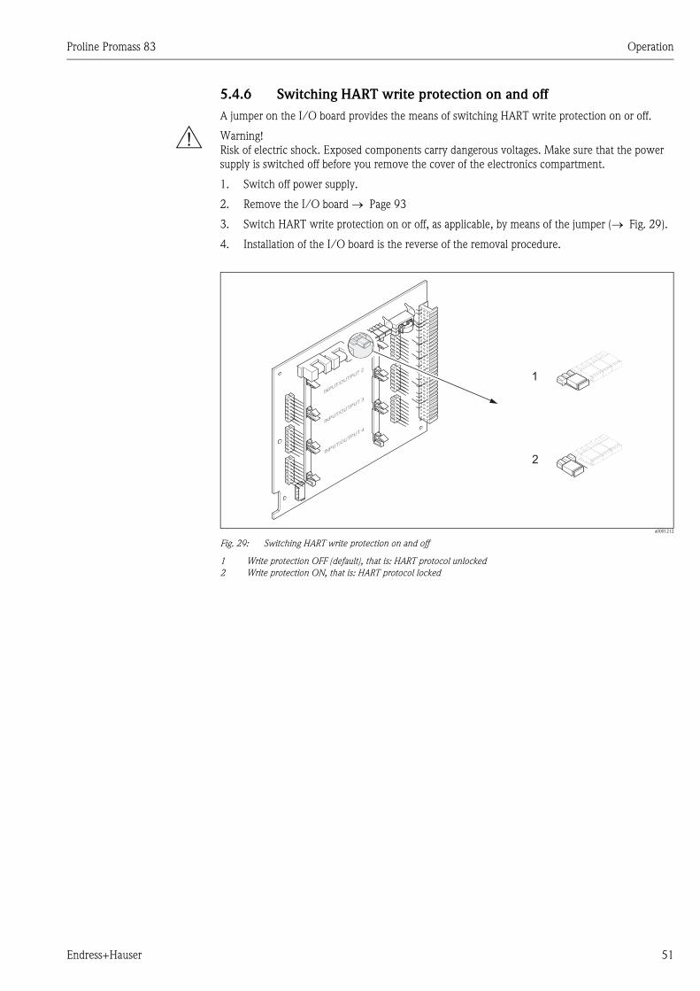
Proline Promass 83 Operation
Endress+Hauser 51
5.4.6 Switching HART write protection on and off
A jumper on the I/O board provides the means of switching HART write protection on or off.
# Warning!
Risk of electric shock. Exposed components carry dangerous voltages. Make sure that the power
supply is switched off before you remove the cover of the electronics compartment.
1. Switch off power supply.
2. Remove the I/O board → Page 93
3. Switch HART write protection on or off, as applicable, by means of the jumper (→ Fig. 29).
4. Installation of the I/O board is the reverse of the removal procedure.
a0001212
Fig. 29: Switching HART write protection on and off
1 Write protection OFF (default), that is: HART protocol unlocked
2 Write protection ON, that is: HART protocol locked
1
2IN
PUT/OUTPUT
4
INPUT/O
UTPUT3
INPUT/O
UTPUT2
Commissioning Proline Promass 83
52 Endress+Hauser
6 Commissioning
6.1 Function check
Make sure that the following function checks have been performed successfully before switching on
the supply voltage for the measuring device:
• Checklist for "Post-installation check" → Page 23
• Checklist for "Post-connection check" → Page 30
6.2 Switching on the measuring device
Once the function check has been performed successfully, the device is operational and can be
switched on via the supply voltage. The device then performs internal test functions and the
following messages are shown on the local display:
Normal measuring mode commences as soon as startup completes.
Various measured value and/or status variables appear on the display (HOME position).
! Note!
If startup fails, an error message indicating the cause is displayed.
PROMASS 83
START-UP
RUNNING
Startup message
▼
PROMASS 83
DEVICE SOFTWARE
V XX.XX.XX
Current software version
▼
CURRENT OUTPUT
FREQUENCY OUTPUT
RELAY
STATUS INPUT
List of installed input/output modules
▼
SYSTEM OK
→ OPERATION
Beginning of normal measuring mode
▼
Proline Promass 83 Commissioning
Endress+Hauser 53
6.3 Quick Setup
In the case of measuring devices without a local display, the individual parameters and functions
must be configured via the configuration program, e.g. FieldCare or ToF Tool - Fieldtool Package.
If the measuring device is equipped with a local display, all the important device parameters for
standard operation, as well as additional functions, can be configured quickly and easily by means
of the following Quick Setup menus.
6.3.1 Quick Setup "Commissioning"
a0004561-en
Fig. 30: "QUICK SETUP COMMISSIONING"- menu for straightforward configuration of the major device functions
04200400
6461
0421 6462
6463
6464
4200
4221
4222
4223
4225
4227
4226
4000
4001
4002
4004
4006
4003
4005
4201
4203
4204
4206
4208
4209
4205
4207
0422
646030013001
04040402
2000
1002B
++E +E
n
o
p
q
r
Esc
E+-
XXX.XXX.XX
m
s Batching
Yes
Yes
Yes
No
No
No
No
Configure another system unit ?
Current output n Freq./Pulse output n
Selection output type
Automatic configuration of display ?
Carrying out another Quick Setup ?
Quit
AssignCurrent output
Current span
Value 0/4 mA
Value 20 mA
Meas. mode Meas. mode
Meas. mode
Time constant
Time constantFailsafe mode
Failsafe mode
Failsafe mode
AssignFreq. output
End value freq.
Value F Low
Value F High
Output signal
AssignPulse output
Pulse value
Pulse width
Output signal
Operation Mode
Frequency Pulse
Automatic parameterization of the display
Reference Calculated
Fix. Density
Density
UnitRef. Density Exp. Coeff. Lin
Exp. Coeff. SQR
Reference temp.
Volume flow Corr. Vol. flowMass flow Density
Selection system units
Temperature Quit
UnitVolume flow
UnitCorr. Vol. flow
UnitMass flow
UnitDensity
UnitTemperature
UnitTotalizer
Corr. Vol.calculation
UnitTotalizer
Language
Pre-setting
Quick Setup
HOME-POSITION
QSCommission
Pulsating flow Gas measurement
Configure another output ?
Carrying out the selected Quick Setup
Selection pre-settings
Actual SettingsDeliver Settingsy
Commissioning Proline Promass 83
54 Endress+Hauser
! Note!
• The display returns to the cell SETUP COMMISSIONING (1002) if you press the Q key combination during
parameter interrogation The stored parameters remain valid.
• The "Commissioning" Quick Setup must be carried out before one of the Quick Setups explained below is run.
m The "DELIVERY SETTING" option sets every selected unit to the factory setting.
The "ACTUAL SETTING" option accepts the units you previously configured.
n Only units not yet configured in the current Setup are offered for selection in each cycle. The unit for mass, volume
and corrected volume is derived from the corresponding flow unit.
o The "YES" option remains visible until all the units have been configured. "NO" is the only option displayed when
no further units are available.
p Only outputs not yet configured in the current Setup are offered for selection in each cycle.
q The "YES" option remains visible until all the outputs have been configured. "NO" is the only option displayed
when no further outputs are available.
r The "automatic parameterization of the display" option contains the following basic settings/factory settings:
YES: Main line = Mass flow; Additional line = Totalizer 1;
Information line = Operating/system conditions
NO: The existing (selected) settings remain.
s The QUICK SETUP BATCHING is only available when the optional software package BATCHING is installed.
Proline Promass 83 Commissioning
Endress+Hauser 55
6.3.2 "Pulsating Flow" Quick Setup menu
Certain types of pump such as reciprocating, peristaltic and cam-type pumps, for example, create a
flow characterized by severe periodic fluctuations. Negative flows can occur with pumps of these
types on account of the closing volume of the valves or valve leaks.
! Note!
Before carrying out the Quick Setup "Pulsating Flow" the Quick Setup "Commissioning. → Page 53
a0001213
Fig. 31: Flow characteristics of various types of pump
A With severely pulsating flow
B With low pulsating flow
1 1-cylinder cam pump
2 2-cylinder cam pump
3 Magnetic pump
4 Peristaltic pump, flexible connecting hose
5 Multi-cylinder reciprocating pump
Severely pulsating flow
Once several device functions have been configured in the "Pulsating flow" Quick Setup menu, flow
fluctuations of this nature can be compensated over the entire flow range and pulsating fluid flows
measured correctly. You will find detailed instructions on how to use this Quick Setup menu below.
! Note!
It is always advisable to work through the "Pulsating flow" Quick Setup menu if there is any
uncertainty about the exact flow characteristic.
Slightly pulsating flow
If flow fluctuations are no more than minor, as is the case, for example with gear-type, three-
cylinder or multi-cylinder pumps, it is not absolutely necessary to work through the Quick Setup
menu.
In cases of this nature, however, it is advisable to adapt the functions listed below (see the
"Description of Device Functions" manual) to suit local process conditions in order to ensure a
stable, unvarying output signal. This applies in particular to the current output:
• Measuring system damping: FLOW DAMPING function → increase value
• Current output damping: TIME CONSTANT function → increase the value
Q
Q
Q Q
Q
t
t
t t
t
1
3
2 5
4
A B
Commissioning Proline Promass 83
56 Endress+Hauser
Performing the "Pulsating flow" Quick Setup
This Quick Setup menu guides you systematically through the setup procedure for all the device
functions that have to be parameterized and configured for measuring pulsating flows. Note that this
has no effect on values configured beforehand, such as measuring range, current range or full scale
value!
a0002615-en
Fig. 32: Quick Setup for measuring severely pulsating flows.
Recommended settings are found on the following page.
! Note!
• The display returns to the cell QUICK SETUP PULSATING FLOW (1003) if you press the Q key
combination during parameter interrogation.
• The Setups can be called up either directly after the "COMMISSIONING" Quick Setup or
manually by means of the QUICK SETUP PULSATING FLOW (1003) function.
++E
+E
3002 3002 3002
4200
4225
8005
6400
6402
6403
6404
4206
4208
4004
4005
B
2002
1003
Esc
E+-
XXX.XXX.XX
Yes
Yes
No
No
n Configure another totalizer ?
o
Current output n Freq.-/Puse output n
Selection of output type
Quit
m
Totalizer 2Totalizer 1 Totalizer 3
Selection totalizer
Quit
Totalizermode (DAA)
Totalizermode (DAB)
Totalizermode (DAC)
Frequency Pulse
Operation mode
Measuring mode
Alarm delay
AssignLF-Cut off
On-valueLF-Cut off
Off-valueLF-Cut off
Pressureshock suppression
QuitQuick Setup
Measuring mode
Time constant
Measuring mode
Time constant
Quick Setup
HOME-POSITION
Displaydamping
QSPlusating Flow
p Configure another output ?
m Only the counters not yet configured in the current Setup are offered for selection in each cycle.
n The "YES" option remains visible until all the counters have been configured. "NO" is the only option displayed when
no further counters are available.
o Only the outputs not yet configured in the current Setup are offered for selection in each cycle.
p The "YES" option remains visible until all the outputs have been configured. "NO" is the only option displayed when
no further outputs are available.
Proline Promass 83 Commissioning
Endress+Hauser 57
Recommended settings
"Pulsating Flow" Quick Setup menu
HOME-Position → F → MEASURED VARIABLE (A)
MEASURED VARIABLE → O → QUICK SETUP (B)
QUICK SETUP → N → QS PULS. FLOW (1003)
Function No. Function name Selection with ( P )
1003 QS PULSATING FLOW YES
After F is pressed by way of confirmation, the
Quick Setup menu calls up all the subsequent
functions in succession.
Æ
Basic configuration
2002 DISPLAY DAMPING 1 s
3002 TOTALIZER MODE (DAA) BALANCE (Totalizer 1)
3002 TOTALIZER MODE (DAB) BALANCE (Totalizer 2)
3002 TOTALIZER MODE (DAC) BALANCE (Totalizer 3)
Signal type for "CURRENT OUTPUT 1 to n"
4004 MEASURING MODE PULSATING FLOW
4005 TIME CONSTANT 1 s
Signal type for "FREQ./PULSE OUTPUT 1 to n" (for FREQUENCY operating mode)
4206 MEASURING MODE PULSATING FLOW
4208 TIME CONSTANT 0 s
Signal type for "FREQ./PULSE OUTPUT 1 to n" (for PULSE operating mode)
4225 MEASURING MODE PULSATING FLOW
Other settings
8005 ALARM DELAY 0 s
6400 ASSIGN LOW FLOW CUTOFF MASS FLOW
6402 ON-VALUE LOW FLOW CUTOFF Setting depends on diameter:
DN 1 = 0.02 [kg/h] or [l/h]
DN 2 = 0.10 [kg/h] or [l/h]
DN 4 = 0.45 [kg/h] or [l/h]
DN 8 = 2.0 [kg/h] or [l/h]
DN 15 = 6.5 [kg/h] or [l/h]
DN 15 FB = 18 [kg/h] resp. [l/h]
DN 25 = 18 [kg/h] resp. [l/h]
DN 25 FB = 45 [kg/h] resp. [l/h]
DN 40 = 45 [kg/h] resp. [l/h]
DN 40 FB = 70 [kg/h] resp. [l/h]
DN 50 = 70 [kg/h] resp. [l/h]
DN 50 FB = 180 [kg/h] resp. [l/h]
DN 80 = 180 [kg/h] or [l/h]
DN 100 = 350 [kg/h] or [l/h]
DN 150 = 650 [kg/h] or [l/h]
DN 250 = 1800 [kg/h] or [l/h]
FB = Full bore versions of Promass I
6403 OFF-VALUE LOW FLOW CUTOFF 50%
6404 PRESSURE SHOCK SUPPRESSION 0 s
Æ
Back to the HOME position:
→ Press and hold down Esc key X for longer than three seconds or
→ Repeatedly press and release Esc key X → Exit the function matrix step by step
Commissioning Proline Promass 83
58 Endress+Hauser
6.3.3 "Batching" Quick Setup menu
This Quick Setup menu guides you systematically through the setup procedure for all the device
functions that have to be parameterized and configured for batching operation. These basic settings
allow simple (one step) batching processes.
Additional settings, e.g. for the calculation of after runs or for multi-stage batching procedures, must
be made via the function matrix itself (see the "Description of Device Functions" manual).
" Caution!
The "Batching" Quick Setup sets certain device parameters for discontinuous measurement
operation.
If the measuring instrument is used for continuous flow measurement at a later time, we
recommend at you rerun the "Commissioning" and/or "Pulsating Flow" Quick Setup.
! Note!
• Before carrying out the Quick Setup "Batching" the Quick Setup "Commissioning" has to be
executed. → Page 53
• This function is only available when the additional "batching" software is installed in the
measuring device (order option). You can order this software from E+H as an accessory at a later
date. → Page 80
• You can find detailed information on the batching functions in the separate "Description of Device
Functions" manual".
• You can also directly control filling process using the local display. During Quick Setup, an
appropriate dialog appears concerning the automatic display configuration. Acknowledge this by
clicking "YES".
This assigns special batching functions (START, PRESET, MATRIX) to the bottom line of the
display. These can be directly executed onsite using the three operating keys ( O / S / F ).
Therefore, the measuring device can be fully deployed in the field as a "batch controller".
→ Page 35
Proline Promass 83 Commissioning
Endress+Hauser 59
a0004644-en
Fig. 33: Quick Setup "Batching"
Recommended settings are found on the following page.
Esc
E+-
XXX.XXX.XX
+
B
6402
6603
6404
7200
7201
7203
7204
1005
4700
4780
7240
+E
E
ON-ValueLow flow cut off
Flowdamping
Pressure shocksuppression
BatchSelector
BatchName
BatchQuantity
FixCompensation Quantity
AssignRelay
Terminal No.
Max. BatchTime
QSBatching/Dosing
YES NOBatch
Supervision?
YES NOAutom. Configuration
Display?
Automatic parameterizationof the display
Quick Setup
Quit Quick Setup
Locked Access CustomerPRESET
Batch quantity
Relay 1 Relay 2Select
Output?
HOME-POSITION
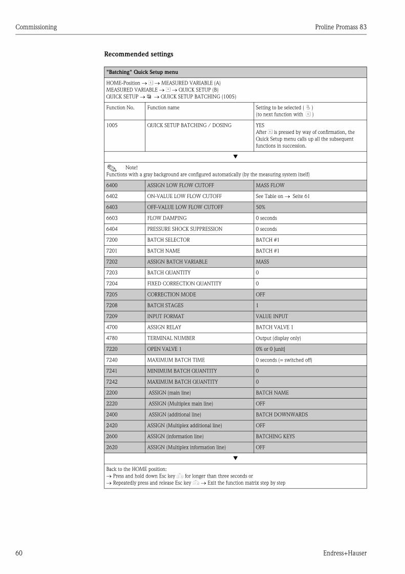
Commissioning Proline Promass 83
60 Endress+Hauser
Recommended settings
"Batching" Quick Setup menu
HOME-Position → F → MEASURED VARIABLE (A)
MEASURED VARIABLE → O → QUICK SETUP (B)
QUICK SETUP → N → QUICK SETUP BATCHING (1005)
Function No. Function name Setting to be selected ( P )
(to next function with F )
1005 QUICK SETUP BATCHING / DOSING YES
After F is pressed by way of confirmation, the
Quick Setup menu calls up all the subsequent
functions in succession.
▼
! Note!
Functions with a gray background are configured automatically (by the measuring system itself)
6400 ASSIGN LOW FLOW CUTOFF MASS FLOW
6402 ON-VALUE LOW FLOW CUTOFF See Table on → Seite 61
6403 OFF-VALUE LOW FLOW CUTOFF 50%
6603 FLOW DAMPING 0 seconds
6404 PRESSURE SHOCK SUPPRESSION 0 seconds
7200 BATCH SELECTOR BATCH #1
7201 BATCH NAME BATCH #1
7202 ASSIGN BATCH VARIABLE MASS
7203 BATCH QUANTITY 0
7204 FIXED CORRECTION QUANTITY 0
7205 CORRECTION MODE OFF
7208 BATCH STAGES 1
7209 INPUT FORMAT VALUE INPUT
4700 ASSIGN RELAY BATCH VALVE 1
4780 TERMINAL NUMBER Output (display only)
7220 OPEN VALVE 1 0% or 0 [unit]
7240 MAXIMUM BATCH TIME 0 seconds (= switched off)
7241 MINIMUM BATCH QUANTITY 0
7242 MAXIMUM BATCH QUANTITY 0
2200 ASSIGN (main line) BATCH NAME
2220 ASSIGN (Multiplex main line) OFF
2400 ASSIGN (additional line) BATCH DOWNWARDS
2420 ASSIGN (Multiplex additional line) OFF
2600 ASSIGN (information line) BATCHING KEYS
2620 ASSIGN (Multiplex information line) OFF
▼
Back to the HOME position:
→ Press and hold down Esc key X for longer than three seconds or
→ Repeatedly press and release Esc key X → Exit the function matrix step by step
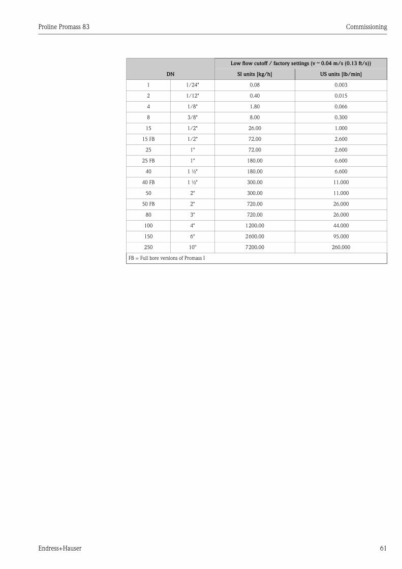
Proline Promass 83 Commissioning
Endress+Hauser 61
DN
Low flow cutoff / factory settings (v & 0.04 m/s (0.13 ft/s))
SI units [kg/h] US units [lb/min]
1 1/24" 0.08 0.003
2 1/12" 0.40 0.015
4 1/8" 1.80 0.066
8 3/8" 8.00 0.300
15 1/2" 26.00 1.000
15 FB 1/2" 72.00 2.600
25 1" 72.00 2.600
25 FB 1" 180.00 6.600
40 1 ½" 180.00 6.600
40 FB 1 ½" 300.00 11.000
50 2" 300.00 11.000
50 FB 2" 720.00 26.000
80 3" 720.00 26.000
100 4" 1200.00 44.000
150 6" 2600.00 95.000
250 10" 7200.00 260.000
FB = Full bore versions of Promass I
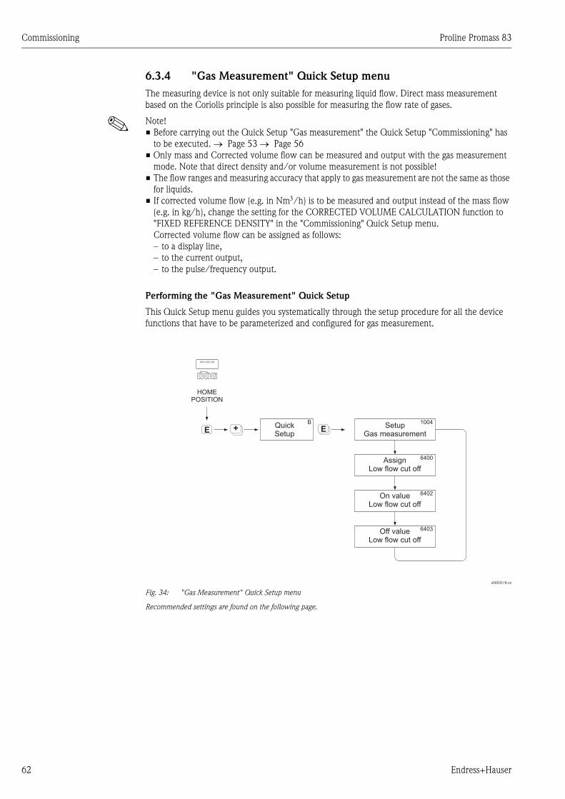
Commissioning Proline Promass 83
62 Endress+Hauser
6.3.4 "Gas Measurement" Quick Setup menu
The measuring device is not only suitable for measuring liquid flow. Direct mass measurement
based on the Coriolis principle is also possible for measuring the flow rate of gases.
! Note!
• Before carrying out the Quick Setup "Gas measurement" the Quick Setup "Commissioning" has
to be executed. → Page 53 → Page 56
• Only mass and Corrected volume flow can be measured and output with the gas measurement
mode. Note that direct density and/or volume measurement is not possible!
• The flow ranges and measuring accuracy that apply to gas measurement are not the same as those
for liquids.
• If corrected volume flow (e.g. in Nm3/h) is to be measured and output instead of the mass flow
(e.g. in kg/h), change the setting for the CORRECTED VOLUME CALCULATION function to
"FIXED REFERENCE DENSITY" in the "Commissioning" Quick Setup menu.
Corrected volume flow can be assigned as follows:
– to a display line,
– to the current output,
– to the pulse/frequency output.
Performing the "Gas Measurement" Quick Setup
This Quick Setup menu guides you systematically through the setup procedure for all the device
functions that have to be parameterized and configured for gas measurement.
a0002618-en
Fig. 34: "Gas Measurement" Quick Setup menu
Recommended settings are found on the following page.
++E
1004B
6400
6402
6403
E
Esc
E+-
XXX.XXX.XX
SetupGas measurement
QuickSetup
AssignLow flow cut off
On valueLow flow cut off
Off valueLow flow cut off
HOMEPOSITION
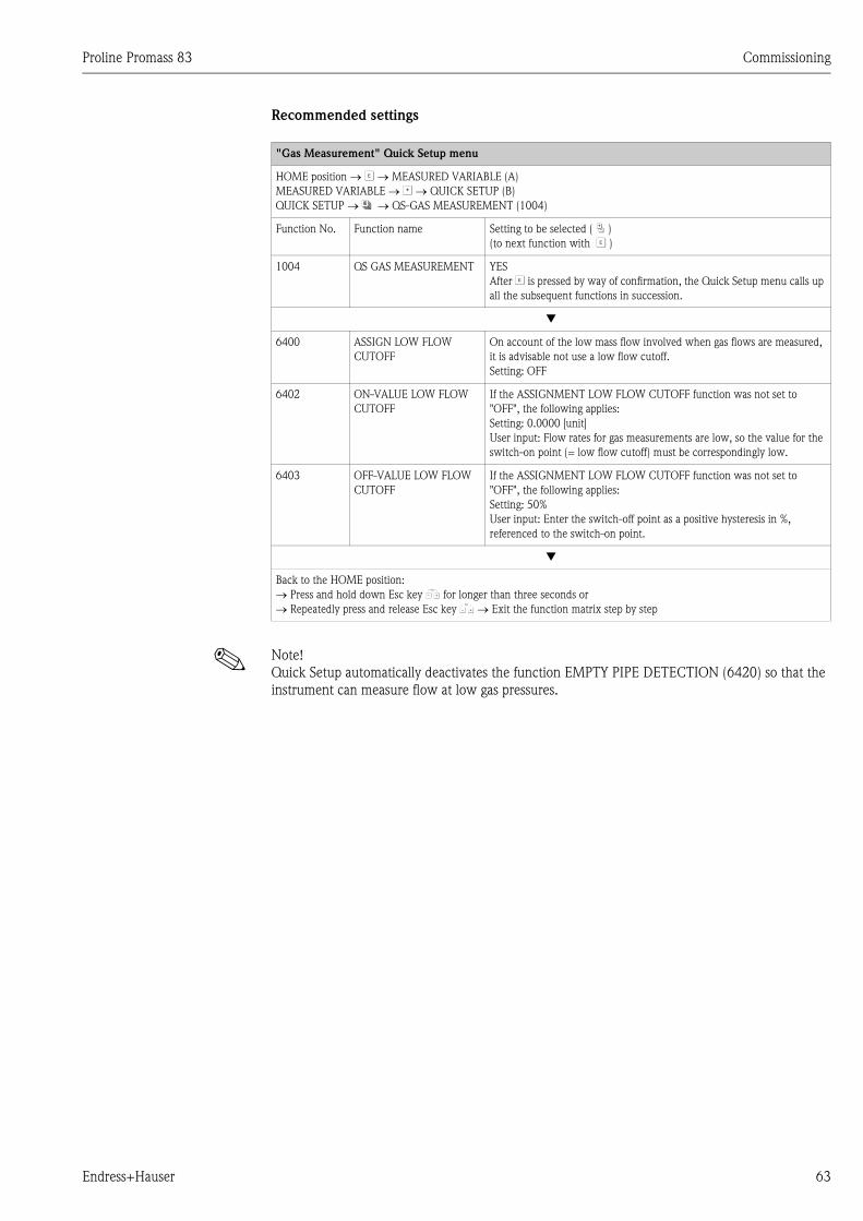
Proline Promass 83 Commissioning
Endress+Hauser 63
Recommended settings
! Note!
Quick Setup automatically deactivates the function EMPTY PIPE DETECTION (6420) so that the
instrument can measure flow at low gas pressures.
"Gas Measurement" Quick Setup menu
HOME position → F → MEASURED VARIABLE (A)
MEASURED VARIABLE → O → QUICK SETUP (B)
QUICK SETUP → N → QS-GAS MEASUREMENT (1004)
Function No. Function name Setting to be selected ( P )
(to next function with F )
1004 QS GAS MEASUREMENT YES
After F is pressed by way of confirmation, the Quick Setup menu calls up
all the subsequent functions in succession.
▼
6400 ASSIGN LOW FLOW
CUTOFF
On account of the low mass flow involved when gas flows are measured,
it is advisable not use a low flow cutoff.
Setting: OFF
6402 ON-VALUE LOW FLOW
CUTOFF
If the ASSIGNMENT LOW FLOW CUTOFF function was not set to
"OFF", the following applies:
Setting: 0.0000 [unit]
User input: Flow rates for gas measurements are low, so the value for the
switch-on point (= low flow cutoff) must be correspondingly low.
6403 OFF-VALUE LOW FLOW
CUTOFF
If the ASSIGNMENT LOW FLOW CUTOFF function was not set to
"OFF", the following applies:
Setting: 50%
User input: Enter the switch-off point as a positive hysteresis in %,
referenced to the switch-on point.
▼
Back to the HOME position:
→ Press and hold down Esc key X for longer than three seconds or
→ Repeatedly press and release Esc key X → Exit the function matrix step by step
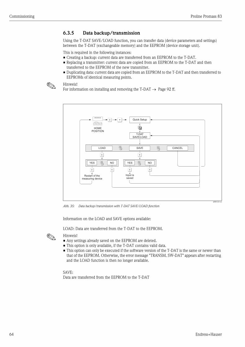
Commissioning Proline Promass 83
64 Endress+Hauser
6.3.5 Data backup/transmission
Using the T-DAT SAVE/LOAD function, you can transfer data (device parameters and settings)
between the T-DAT (exchangeable memory) and the EEPROM (device storage unit).
This is required in the following instances:
• Creating a backup: current data are transferred from an EEPROM to the T-DAT.
• Replacing a transmitter: current data are copied from an EEPROM to the T-DAT and then
transferred to the EEPROM of the new transmitter.
• Duplicating data: current data are copied from an EEPROM to the T-DAT and then transferred to
EEPROMs of identical measuring points.
! Hinweis!
For information on installing and removing the T-DAT → Page 92 ff.
a0001221-en
Abb. 35: Data backup/transmission with T-DAT SAVE/LOAD function
Information on the LOAD and SAVE options available:
LOAD: Data are transferred from the T-DAT to the EEPROM.
! Hinweis!
• Any settings already saved on the EEPROM are deleted.
• This option is only available, if the T-DAT contains valid data.
• This option can only be executed if the software version of the T-DAT is the same or newer than
that of the EEPROM. Otherwise, the error message "TRANSM. SW-DAT" appears after restarting
and the LOAD function is then no longer available.
SAVE:
Data are transferred from the EEPROM to the T-DAT
FEsc
E+-
XXX.XXX.XX
F F
FF FF
P P
PP
N
O
T-DATSAVE/LOAD
Quick Setup
HOMEPOSITION
LOAD
YES NO
CANCELSAVE
YES NO
Restart of themeasuring device
Input issaved
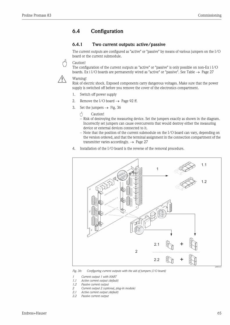
Proline Promass 83 Commissioning
Endress+Hauser 65
6.4 Configuration
6.4.1 Two current outputs: active/passive
The current outputs are configured as "active" or "passive" by means of various jumpers on the I/O
board or the current submodule.
" Caution!
The configuration of the current outputs as "active" or "passive" is only possible on non-Ex i I/O
boards. Ex i I/O boards are permanently wired as "active" or "passive". See Table → Page 27
# Warning!
Risk of electric shock. Exposed components carry dangerous voltages. Make sure that the power
supply is switched off before you remove the cover of the electronics compartment.
1. Switch off power supply
2. Remove the I/O board → Page 92 ff.
3. Set the jumpers → Fig. 36
" Caution!
– Risk of destroying the measuring device. Set the jumpers exactly as shown in the diagram.
Incorrectly set jumpers can cause overcurrents that would destroy either the measuring
device or external devices connected to it.
– Note that the position of the current submodule on the I/O board can vary, depending on
the version ordered, and that the terminal assignment in the connection compartment of the
transmitter varies accordingly. → Page 27
4. Installation of the I/O board is the reverse of the removal procedure.
a0001214
Fig. 36: Configuring current outputs with the aid of jumpers (I/O board)
1 Current output 1 with HART
1.1 Active current output (default)
1.2 Passive current output
2 Current output 2 (optional, plug-in module)
2.1 Active current output (default)
2.2 Passive current output
INPUT/O
UTPUT4
2
1
2.1
1.1
2.2
1.2
+
+
INPUT/O
UTPUT3
INPUT/O
UTPUT2
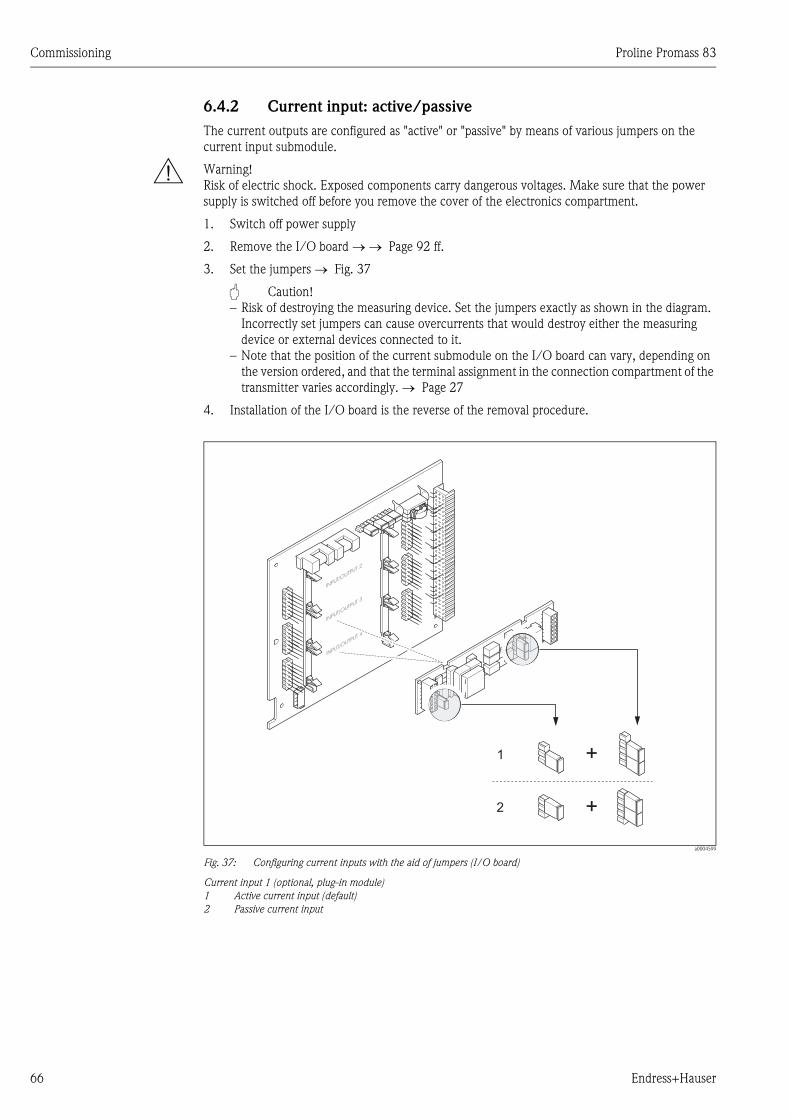
Commissioning Proline Promass 83
66 Endress+Hauser
6.4.2 Current input: active/passive
The current outputs are configured as "active" or "passive" by means of various jumpers on the
current input submodule.
# Warning!
Risk of electric shock. Exposed components carry dangerous voltages. Make sure that the power
supply is switched off before you remove the cover of the electronics compartment.
1. Switch off power supply
2. Remove the I/O board → → Page 92 ff.
3. Set the jumpers → Fig. 37
" Caution!
– Risk of destroying the measuring device. Set the jumpers exactly as shown in the diagram.
Incorrectly set jumpers can cause overcurrents that would destroy either the measuring
device or external devices connected to it.
– Note that the position of the current submodule on the I/O board can vary, depending on
the version ordered, and that the terminal assignment in the connection compartment of the
transmitter varies accordingly. → Page 27
4. Installation of the I/O board is the reverse of the removal procedure.
a0004599
Fig. 37: Configuring current inputs with the aid of jumpers (I/O board)
Current input 1 (optional, plug-in module)
1 Active current input (default)
2 Passive current input
INPUT/O
UTPUT 4
1
2 +
+
INPUT/O
UTPUT 3
INPUT/O
UTPUT 2
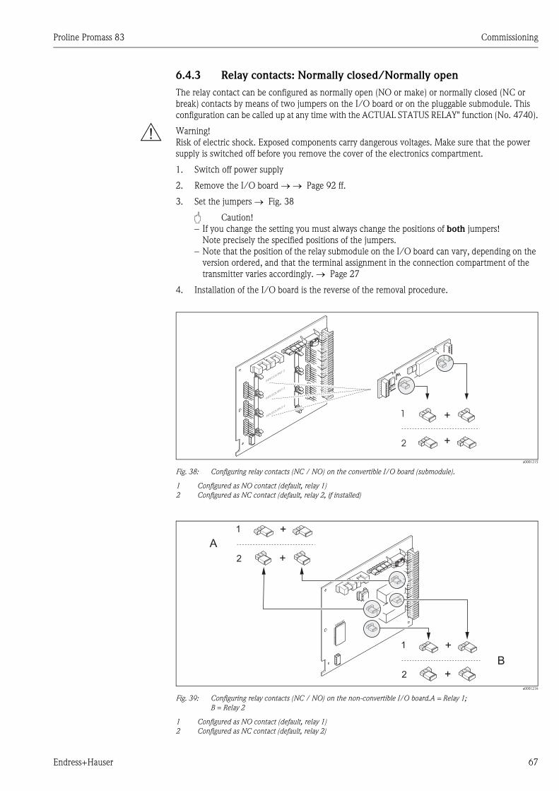
Proline Promass 83 Commissioning
Endress+Hauser 67
6.4.3 Relay contacts: Normally closed/Normally open
The relay contact can be configured as normally open (NO or make) or normally closed (NC or
break) contacts by means of two jumpers on the I/O board or on the pluggable submodule. This
configuration can be called up at any time with the ACTUAL STATUS RELAY" function (No. 4740).
# Warning!
Risk of electric shock. Exposed components carry dangerous voltages. Make sure that the power
supply is switched off before you remove the cover of the electronics compartment.
1. Switch off power supply
2. Remove the I/O board → → Page 92 ff.
3. Set the jumpers → Fig. 38
" Caution!
– If you change the setting you must always change the positions of both jumpers!
Note precisely the specified positions of the jumpers.
– Note that the position of the relay submodule on the I/O board can vary, depending on the
version ordered, and that the terminal assignment in the connection compartment of the
transmitter varies accordingly. → Page 27
4. Installation of the I/O board is the reverse of the removal procedure.
a0001215
Fig. 38: Configuring relay contacts (NC / NO) on the convertible I/O board (submodule).
1 Configured as NO contact (default, relay 1)
2 Configured as NC contact (default, relay 2, if installed)
a0001216
Fig. 39: Configuring relay contacts (NC / NO) on the non-convertible I/O board.A = Relay 1;
B = Relay 2
1 Configured as NO contact (default, relay 1)
2 Configured as NC contact (default, relay 2)
INPUT/O
UTPUT 4
INPUT/O
UTPUT 3
+
+1
2
INPUT/O
UTPUT 2
+
+
1
2
+
+
1
A
B
2
Commissioning Proline Promass 83
68 Endress+Hauser
6.4.4 Concentration measurement
The measuring device determines three primary variables simultaneously:
• Mass flow
• Fluid density
• Fluid temperature
As standard, these measured variables allow other process variables to be calculated, such as volume
flow, reference density (density at reference temperature) and corrected volume flow.
The optional software package "Concentration measurement" (F-Chip, accessories) offers a
multitude of additional density functions. Additional evaluation methods are available in this way,
especially for special density calculations in all types of applications: → Page 80
• Calculating percentage contents, mass and volume flow in two-phase media (carrier fluid and
target fluid),
• Converting density of the fluid into special density units (°Brix, °Baumé, °API, etc.).
Concentration measurement with fixed calculation function
By means of the DENSITY FUNCTION (7000) function, you can select various density functions
which use a fixed specified calculation mode for calculating concentration:
Density function Remarks
%-MASS
%-VOLUME
By using the functions for two-phase-media, it is possible to calculate the percentage mass or
volume contents of the carrier fluid or the target fluid. The basic equations (without temperature
compensation) are:
a0004610-en
a0004619-en
D1 = density of carrier fluid (transporting liquid, e.g. water)
D2 = density of target fluid (material transported, e.g. lime powder or a second liquefied material
to be measured)
ρ = measured overall density
°BRIX Density unit used for the Food & Beverage industry which deals with the saccharose content of
aqueous solutions, e.g. for measuring solutions containing sugar such as fruit juice, etc.
The following ICUMSA table for Brix units is the basis for calculations within the device.
°BAUME This density unit or scale is mainly used for acidic solutions, e.g. ferric chloride solutions.
Two Baumé scales are used in practice:
– BAUME > 1 kg/l: for solutions heavier than water
– BAUME < 1 kg/l: for solutions lighter than water
°BALLING
°PLATO
Both units are a commonly used basis for calculating the fluid density in the brewery industry. A
liquid with a value of 1° BALLING (Plato) has the same fluid density as a water/cane sugar
solution consisting of 1 kg cane sugar dissolved in 99 kg of water. 1° Balling (Plato) is thus 1% of
the liquid weight.
%-BLACK LIQUOR The units of concentration used in the paper industry for black liquor in % by mass. The formula
used for the calculation is the same as for %-MASS.
°API °API (= American Petroleum Institute)
Density units specifically used in North America for liquefied oil products.
D2 · (� – D1)
·(D2 – D1)�·100%Mass [%] =
(� – D1)
(D2 – D1)·100%Volume =[%]
Proline Promass 83 Commissioning
Endress+Hauser 69
a0004598-en
Fig. 40: Selecting and configuring different density functions in the function matrix
++E E
H
700
HAA
7000
7001
7002
7003
7004
7005
7006
7009
7007
7008
7007
7008
7009
Densityfunctions
Specialfunction
Configuration
Densityfunction
Selection
HOMEPOSITION
Reference densityCarrier fluid
Expansion coeff. linearCarrier fluid
Expansion coeff. sqr.Carrier fluid
Reference densityTarget fluid
Expansion coeff. linearTarget fluid
Expansion coeff. sqr.Target fluid
Referencetemperature
% MASS% VOLUME
° BRIX
° API° BAUME° PLATO° BALLING
see separatedescription
FLEXIBLE
Expansioncoefficient linear
Expansioncoefficient square
Expansioncoefficient linear
Expansioncoefficient square
Referencetemperature
Esc
E+-
XXX.XXX.XX
Brixgrade (density of hydrous saccharose solution in kg/m³)
°Brix 10°C 20°C 30°C 40°C 50°C 60°C 70°C 80°C
0 999.70 998.20 995.64 992.21 988.03 983.19 977.76 971.78
5 1019.56 1017.79 1015.03 1011.44 1007.14 1002.20 996.70 989.65
10 1040.15 1038.10 1035.13 1031.38 1026.96 1021.93 1016.34 1010.23
15 1061.48 1059.15 1055.97 1052.08 1047.51 1042.39 1036.72 1030.55
20 1083.58 1080.97 1077.58 1073.50 1068.83 1063.60 1057.85 1051.63
25 1106.47 1103.59 1099.98 1095.74 1090.94 1085.61 1079.78 1073.50
30 1130.19 1127.03 1123.20 1118.80 1113.86 1108.44 1102.54 1096.21
35 1154.76 1151.33 1147.58 1142.71 1137.65 1132.13 1126.16 1119.79
40 1180.22 1176.51 1172.25 1167.52 1162.33 1156.71 1150.68 1144.27
45 1206.58 1202.61 1198.15 1193.25 1187.94 1182.23 1176.14 1169.70
Commissioning Proline Promass 83
70 Endress+Hauser
Concentration measurement with flexible calculation function
Under certain application conditions, it may not be possible to use density functions with a fixed
calculation function (% mass, °Brix, etc.). However, user-specific or application-specific
concentration calculations can be used with the "FLEXIBLE" setting in the function
DENSITY FUNCTION (7000).
The following types of calculation can be selected in function MODE (7021):
• % MASS 3D
• % VOLUME 3D
• % MASS 2D
• % VOLUME 2D
• OTHER 3D
• OTHER 2D
Calculation type "% MASS 3D" or "% VOLUME 3D"
For this type of calculation, the relationship between the three variables - concentration, density and
temperature must be known (3-dimensional), e.g. by a table. In this way, the concentration can be
calculated from the measured density and temperature values by means of the following formula
(the coefficients AO, A1, etc. have to be determined by the user):
a0004620
K Concentration
ρ Currently measured density
A0 Value from function (COEFFICIENT A0 (7032))
A1 Value from function (COEFFICIENT A1 (7033)
A2 Value from function (COEFFICIENT A2 (7034)
A3 Value from function (COEFFICIENT A3 (7035)
A4 Value from function (COEFFICIENT A4 (7036)
B1 Value from function (COEFFICIENT B1 (7037)
B2 Value from function (COEFFICIENT B2 (7038)
B3 Value from function (COEFFICIENT B3 (7039)
T Currently measured temperature in °C
50 1233.87 1229.64 1224.98 1219.93 1214.50 1208.70 1202.56 1196.11
55 1262.11 1257.64 1252.79 1247.59 1242.05 1236.18 1229.98 1223.53
60 1291.31 1286.61 1281.59 1276.25 1270.61 1264.67 1258.45 1251.88
65 1321.46 1316.56 1311.38 1305.93 1300.21 1294.21 1287.96 1281.52
70 1352.55 1347.49 1342.18 1336.63 1330.84 1324.80 1318.55 1312.13
75 1384.58 1379.38 1373.88 1368.36 1362.52 1356.46 1350.21 1343.83
80 1417.50 1412.20 1406.70 1401.10 1395.20 1389.20 1383.00 1376.60
85 1451.30 1445.90 1440.80 1434.80 1429.00 1422.90 1416.80 1410.50
Source: A. & L. Emmerich, Technical University of Brunswick; officially recommended by ICUMSA, 20th session 1990
Brixgrade (density of hydrous saccharose solution in kg/m³)
°Brix 10°C 20°C 30°C 40°C 50°C 60°C 70°C 80°C
K = A0 + A1 · + A2 · +A3 · + A4 · +B1 · T + B2 · T + B3 · T� �2 3 4 2 3
� �
Proline Promass 83 Commissioning
Endress+Hauser 71
Example:
The following is a concentration table from a reference source.
! Note!
The coefficients for the Promass 83 concentration algorithm should be determined with the density
in units of kg/liter, temperature in °C and concentration in decimal form (0.50, not 50%). The
coefficients B1, B2 and B3 must be entered in scientific notation into the matrix positions 7037,
7038 and 7039 as a product with 10−3, 10−6 or 10−9
Assume:
Density (ρ): 870 kg/m3 → 0.870 kg/l
Temperature (T): 20°C
Coefficients determined for table above:
A0 = -2.6057
A1 = 11.642
A2 = -8.8571
A3 = 0
A4 = 0
B1 = -2.7747·10-3
B2 = -7.3469·10-6
B3 = 0
Calculation:
a0004620
= -2.6057 + 11.642 · 0.870 + (-8.8571) · 0.870 2 + 0 · 0.870 3 + 0 · 0.870 4 + (-2.7747)·10 −3 · 20
+ (-7.3469)·10 −6 · 20 2 + 0 · 20 3
= 0.7604
= 76.04%
Temperature 10°C 15°C 20°C 25°C 30°C
Density
825 kg/m3 93.6% 92.5% 91.2% 90.0% 88.7%
840 kg/m3 89.3% 88.0% 86.6% 85.2% 83.8%
855 kg/m3 84.4% 83.0% 81.5% 80.0% 78.5%
870 kg/m3 79.1% 77.6% 76.1% 74.5% 72.9%
885 kg/m3 73.4% 71.8% 70.2% 68.6% 66.9%
900 kg/m3 67.3% 65.7% 64.0% 62.3% 60.5%
915 kg/m3 60.8% 59.1% 57.3% 55.5% 53.7%
K = A0 + A1 · + A2 · +A3 · + A4 · +B1 · T + B2 · T + B3 · T� �2 3 4 2 3
� �
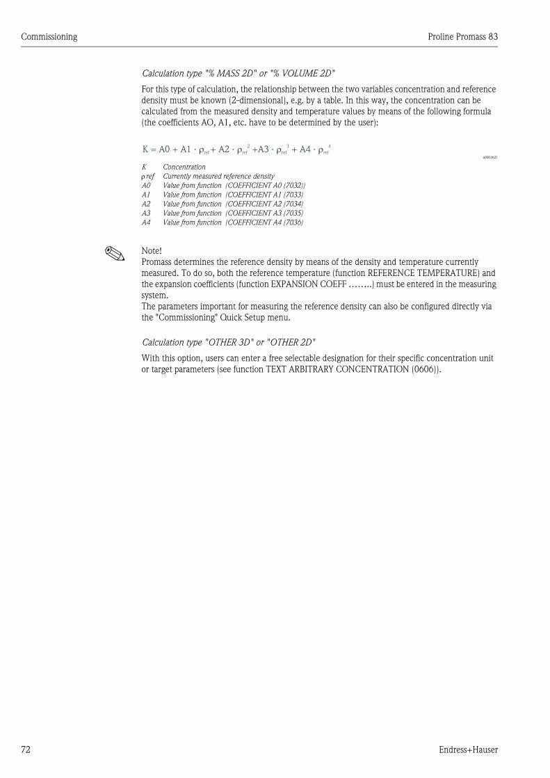
Commissioning Proline Promass 83
72 Endress+Hauser
Calculation type "% MASS 2D" or "% VOLUME 2D"
For this type of calculation, the relationship between the two variables concentration and reference
density must be known (2-dimensional), e.g. by a table. In this way, the concentration can be
calculated from the measured density and temperature values by means of the following formula
(the coefficients AO, A1, etc. have to be determined by the user):
a0004621
K Concentration
ρref Currently measured reference density
A0 Value from function (COEFFICIENT A0 (7032))
A1 Value from function (COEFFICIENT A1 (7033)
A2 Value from function (COEFFICIENT A2 (7034)
A3 Value from function (COEFFICIENT A3 (7035)
A4 Value from function (COEFFICIENT A4 (7036)
! Note!
Promass determines the reference density by means of the density and temperature currently
measured. To do so, both the reference temperature (function REFERENCE TEMPERATURE) and
the expansion coefficients (function EXPANSION COEFF ……..) must be entered in the measuring
system.
The parameters important for measuring the reference density can also be configured directly via
the "Commissioning" Quick Setup menu.
Calculation type "OTHER 3D" or "OTHER 2D"
With this option, users can enter a free selectable designation for their specific concentration unit
or target parameters (see function TEXT ARBITRARY CONCENTRATION (0606)).
K = A0 + A1 · + A2 · +A3 · + A4 ·�ref
2 3 4� � �ref ref ref
Proline Promass 83 Commissioning
Endress+Hauser 73
6.4.5 Advanced diagnostic functions
Changes to the measuring system, e.g. coating buildup or corrosion and abrasion on the measuring
tubes can be detected at an early stage by means of the optional software package "Advanced
Diagnostics" (F-Chip, accessories → Page 80). Normally, these influences reduce the measuring
accuracy of the system or may lead to serious system errors.
By means of the diagnostic functions it is now possible to record various process and device
parameters during operation, e.g. mass flow, density/reference density, temperature values,
measuring tube damping etc.
By analyzing the trend of these measured values, deviations of the measuring system from a
"reference status" can be detected in good time and corrective measures can be taken.
Reference values as the basis for trend analysis
Reference values of the parameters in question must always be recorded for trend analysis. These
reference values are determined under reproducible, constant conditions. Such reference values are
initially recorded during calibration at the factory and saved in the measuring device.
Reference data can also be ascertained under customer-specific process conditions, e.g. during
commissioning or at certain process stages (cleaning cycles, etc.).
Reference values are recorded and saved in the measuring system always by means of the device
function REFERENCE CONDITION USER (7401).
" Caution!
It is not possible to analyze the trend of process/device parameters without reference values!
Reference values can only be determined under constant, non-changing process conditions.
Methods of ascertaining data
Process and device parameters can be recorded in two different ways which you can define in the
function ACQUISITION MODE (7410):
• PERIODICAL option: Measuring device acquires data periodically. Enter the desired time interval
by means of the function ACQUISITION PERIOD (7411).
• SINGLE SHOT option: The user himself acquires the data manually at different, free selectable
periods.
Ensure that the process conditions always correspond to the reference status when data is being
recorded. It is only in this way that deviations from the reference status can be clearly determined.
! Note!
The last ten entries are retained in chronological order in the measuring system.
The "history" of such values can be called up via various functions:
Diagnosis parameters Data saved (per parameter)
Mass flow
Density
Reference density
Temperature
Measuring tube damping
Sensor symmetry
Operating frequency fluctuation
Tube damping fluctuation
Reference value →REFERENCE VALUE function
Lowest measured value → MINIMUM VALUE function
Highest measured value → MAXIMUM VALUE function
List of the last ten measured values → HISTORY function
Deviation measured/reference value → ACTUAL DEVIATION function
More detailed information can be found in the "Description of Device Functions" manual.
Commissioning Proline Promass 83
74 Endress+Hauser
Triggering warning messages
If required, a limit value can be assigned to all the process/device parameters relevant to the
diagnostic functions. A warning message is triggered if this limit value is exceeded → function
WARNING MODE (7403).
The limit value is entered into the measuring system as an absolute (+/-) or relative deviation from
the reference value → function WARNING LEVEL (74…).
Deviations arising and recorded by the measuring system can also be output via the current or relay
outputs.
Data interpretation
The way the data recorded by the measuring system is interpreted depends largely on the
application in question. This means that users must have a very good knowledge of their specific
process conditions and the related deviation tolerances in the process, which have to be determined
by the users themselves in each individual case.
For example, when using the limit function it is especially important to know the minimum and
maximum deviation tolerances allowed. Otherwise there is the danger that a warning message is
triggered inadvertently during "normal" process fluctuations.
There can be various reasons for deviating from the reference status. The following table provides
examples and pointers for each of the six diagnosis parameters recorded:
Diagnosis parameters Possible reasons for deviation
Mass flow A deviation from the reference status indicates possible zero point shift.
Density A deviation from the reference status can be caused by a change in the measuring tube
resonance frequency, e.g. from deposits in the measuring tube, corrosion or abrasion.
Reference density The reference density values can be interpreted in the same way as the density values. If
the fluid temperature cannot be kept completely constant, you can analyze the reference
density (density at a constant temperature, e.g. at 20 °C) instead of the density.
Ensure that the parameters required for calculating the reference density have been
correctly configured (functions REFERENCE TEMPERATURE and EXPANSION COEFF.).
Temperature Use this diagnosis parameter to check the functionality of the PT 100 temperature sensor.
Measuring tube damping A deviation from the reference status can be caused by a change in measuring tube
damping, e.g. from mechanical changes (coating buildup, corrosion, abrasion).
Sensor symmetry Use this diagnosis parameter to determine whether the sensor signals are symmetrical.
Operating frequency
fluctuation
A deviation in the operating frequency fluctuation indicates possible gas content in the
medium.
Tube damping fluctuation A deviation in the tube damping fluctuation indicates possible gas content in the medium.
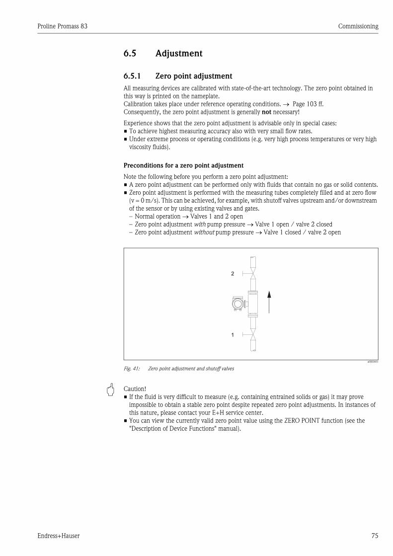
Proline Promass 83 Commissioning
Endress+Hauser 75
6.5 Adjustment
6.5.1 Zero point adjustment
All measuring devices are calibrated with state-of-the-art technology. The zero point obtained in
this way is printed on the nameplate.
Calibration takes place under reference operating conditions. → Page 103 ff.
Consequently, the zero point adjustment is generally not necessary!
Experience shows that the zero point adjustment is advisable only in special cases:
• To achieve highest measuring accuracy also with very small flow rates.
• Under extreme process or operating conditions (e.g. very high process temperatures or very high
viscosity fluids).
Preconditions for a zero point adjustment
Note the following before you perform a zero point adjustment:
• A zero point adjustment can be performed only with fluids that contain no gas or solid contents.
• Zero point adjustment is performed with the measuring tubes completely filled and at zero flow
(v = 0 m/s). This can be achieved, for example, with shutoff valves upstream and/or downstream
of the sensor or by using existing valves and gates.
– Normal operation → Valves 1 and 2 open
– Zero point adjustment with pump pressure → Valve 1 open / valve 2 closed
– Zero point adjustment without pump pressure → Valve 1 closed / valve 2 open
a0003601
Fig. 41: Zero point adjustment and shutoff valves
" Caution!
• If the fluid is very difficult to measure (e.g. containing entrained solids or gas) it may prove
impossible to obtain a stable zero point despite repeated zero point adjustments. In instances of
this nature, please contact your E+H service center.
• You can view the currently valid zero point value using the ZERO POINT function (see the
"Description of Device Functions" manual).
1
2
Commissioning Proline Promass 83
76 Endress+Hauser
Performing a zero point adjustment
1. Operate the system until operating conditions have settled.
2. Stop the flow (v = 0 m/s).
3. Check the shutoff valves for leaks.
4. Check that operating pressure is correct.
5. Using the local display, select the ZEROPOINT ADJUSTMENT function in the function matrix:
BASIC FUNCTIONS → PROCESS PARAMETER → ADJUSTMENT → ZERO POINT
ADJUSTMENT
6. When you press O or S you are automatically prompted to enter the access code if the
function matrix is still disabled. Enter the code (factory setting = 83).
7. Using O or S, now select START and press F to confirm. Click YES to acknowledge the
security prompt and press F again to confirm. Zero point adjustment is now started.
– The message "ZEROPOINT ADJUST RUNNING" appears on the display for 30 to 60 seconds
while adjustment is in progress.
– If the flow in the pipe exceeds 0.1 m/s, the following error message appears on the display:
ZERO ADJUST NOT POSSIBLE.
– When the zero point adjustment completes, the ZERO ADJUSTMENT function reappears on
the display.
8. Back to the HOME position:
– Press and hold down Esc key (X) for longer than three seconds or
– Repeatedly press and release the Esc key (X).
6.5.2 Density adjustment
It is advisable to perform a density adjustment when optimum measuring accuracy is required for
calculating density dependent values. The application may require a 1-point or 2-point density
adjustment.
1-point density adjustment (with one fluid):
This type of density adjustment is necessary under the following circumstances:
• The sensor does not measure exactly the density value that the user expects on the basis of
laboratory analyses.
• The fluid properties are outside the measuring points set at the factory, or the reference operating
conditions used to calibrate the measuring device.
• The system is used exclusively to measure a fluid’s density which must be registered to a high
degree of accuracy under constant conditions.
Example: Brix density measurement for apple juice.
2-point density adjustment (with two fluids):
This type of adjustment is always to be carried out if the measuring tubes have been mechanically
altered by, e.g. material buildup, abrasion or corrosion. In such cases, the resonant frequency of the
measuring tubes has been affected by these factors and is no longer compatible with the calibration
data set at the factory. The 2-point density adjustment takes these mechanically-based changes into
account and calculates new, adjusted calibration data.
Performing a 1-point or 2-point density adjustment
" Caution!
• Onsite density adjustment can be performed only if the user has detailed knowledge of the fluid
density, obtained for example from detailed laboratory analyses.
• The target density value specified in this way must not deviate from the measured fluid density
by more than ±10%.
• An error in defining the target density affects all calculated density and volume functions.
• The 2-point density adjustment is only possible if both target density values are different from
each other by at least 0.2 kg/l. Otherwise the error message #731 (adjustment is not possible)
appears in the "Diag. - Act. Sys. Condition" parameter.
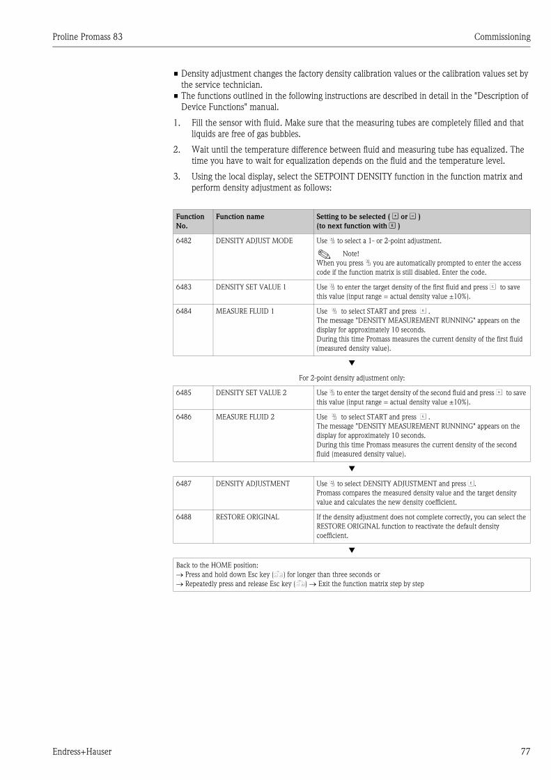
Proline Promass 83 Commissioning
Endress+Hauser 77
• Density adjustment changes the factory density calibration values or the calibration values set by
the service technician.
• The functions outlined in the following instructions are described in detail in the "Description of
Device Functions" manual.
1. Fill the sensor with fluid. Make sure that the measuring tubes are completely filled and that
liquids are free of gas bubbles.
2. Wait until the temperature difference between fluid and measuring tube has equalized. The
time you have to wait for equalization depends on the fluid and the temperature level.
3. Using the local display, select the SETPOINT DENSITY function in the function matrix and
perform density adjustment as follows:
Function
No.
Function name Setting to be selected ( O or S )
(to next function with F )
6482 DENSITY ADJUST MODE Use P to select a 1- or 2-point adjustment.
! Note!
When you press P you are automatically prompted to enter the access
code if the function matrix is still disabled. Enter the code.
6483 DENSITY SET VALUE 1 Use P to enter the target density of the first fluid and press F to save
this value (input range = actual density value ±10%).
6484 MEASURE FLUID 1 Use P to select START and press F .
The message "DENSITY MEASUREMENT RUNNING" appears on the
display for approximately 10 seconds.
During this time Promass measures the current density of the first fluid
(measured density value).
▼
For 2-point density adjustment only:
6485 DENSITY SET VALUE 2 Use P to enter the target density of the second fluid and press F to save
this value (input range = actual density value ±10%).
6486 MEASURE FLUID 2 Use P to select START and press F .
The message "DENSITY MEASUREMENT RUNNING" appears on the
display for approximately 10 seconds.
During this time Promass measures the current density of the second
fluid (measured density value).
▼
6487 DENSITY ADJUSTMENT Use P to select DENSITY ADJUSTMENT and press F.
Promass compares the measured density value and the target density
value and calculates the new density coefficient.
6488 RESTORE ORIGINAL If the density adjustment does not complete correctly, you can select the
RESTORE ORIGINAL function to reactivate the default density
coefficient.
▼
Back to the HOME position:
→ Press and hold down Esc key (X) for longer than three seconds or
→ Repeatedly press and release Esc key (X) → Exit the function matrix step by step
Commissioning Proline Promass 83
78 Endress+Hauser
6.6 Purge and pressure monitoring connections
The sensor housing protects the inner electronics and mechanics and is filled with dry nitrogen.
Beyond that, up to a specified measuring pressure it additionally serves as secondary containment.
# Warning!
For a process pressure above the specified containment pressure, the housing does not serve as an
additional secondary containment. In case a danger of measuring tube failure exists due to process
characteristics, e.g. with corrosive process fluids, we recommend the use of sensors whose housing
is equipped with special pressure monitoring connections (ordering option). With the help of these
connections, fluid collected in the housing in the event of tube failure can be drained off. This
diminishes the danger of mechanical overload of the housing, which could lead to a housing failure
and accordingly is connected with an increased danger potential. These connections can also be
used for gas purging (gas detection).
The following instructions apply to handling sensors with purge or pressure monitoring connections:
• Do not open the purge connections unless the containment can be filled immediately with a dry
inert gas.
• Use only low gauge pressure to purge. Maximum pressure 5 bar.
6.7 Data storage device (HistoROM), F-CHIP
At Endress+Hauser, the term HistoROM refers to various types of data storage modules on which
process and measuring device data are stored. By unplugging and plugging such modules, device
configurations can be duplicated onto other measuring devices to cite just one example.
6.7.1 HistoROM/S-DAT (sensor-DAT)
The S-DAT is an exchangeable data storage device in which all sensor relevant parameters are
stored, i.e., diameter, serial number, calibration factor, zero point.
6.7.2 HistoROM/T-DAT (transmitter-DAT)
The T-DAT is an exchangeable data storage device in which all transmitter parameters and settings
are stored.
Storing of specific parameter settings from the EEPROM to the T-DAT and vice versa has to be
carried out by the user (= manual save function). Detailed instructions regarding this can be found
on Page 64.
6.7.3 F-CHIP (Function-Chip)
The F-Chip is a microprocessor chip that contains additional software packages that extend the
functionality and application possibilities of the transmitter.
In the case of a later upgrade, the F-Chip can be ordered as an accessory and can simply be plugged
on to the I/O board. After start up, the software is immediately made available to the transmitter.
Accessories → Page 80
Plugging onto the I/O board → Page 93 → Page 92
" Caution!
To ensure an unambiguous assignment, the F-CHIP is coded with the transmitter serial number
once it is plugged in. Thus, it cannot be reused with other measuring devices.
Proline Promass 83 Maintenance
Endress+Hauser 79
7 Maintenance
No special maintenance work is required.
7.1 Exterior cleaning
When cleaning the exterior of measuring devices, always use cleaning agents that do not attack the
surface of the housing and the seals.
7.2 Cleaning with pigs (Promass H, I, S, P)
If pigs are used for cleaning, it is essential to take the inside diameters of measuring tube and process
connection into account. See also Technical Information. → Page 128
7.3 Replacing seals
Under normal circumstances, fluid wetted seals of the Promass A and Promass M sensors do not
require replacement. Replacement is necessary only in special circumstances, for example if
aggressive or corrosive fluids are incompatible with the seal material.
! Note!
• The period between changes depends on the fluid properties and on the frequency of cleaning
cycles in the case of CIP/SIP cleaning
• Replacement seals (accessories)
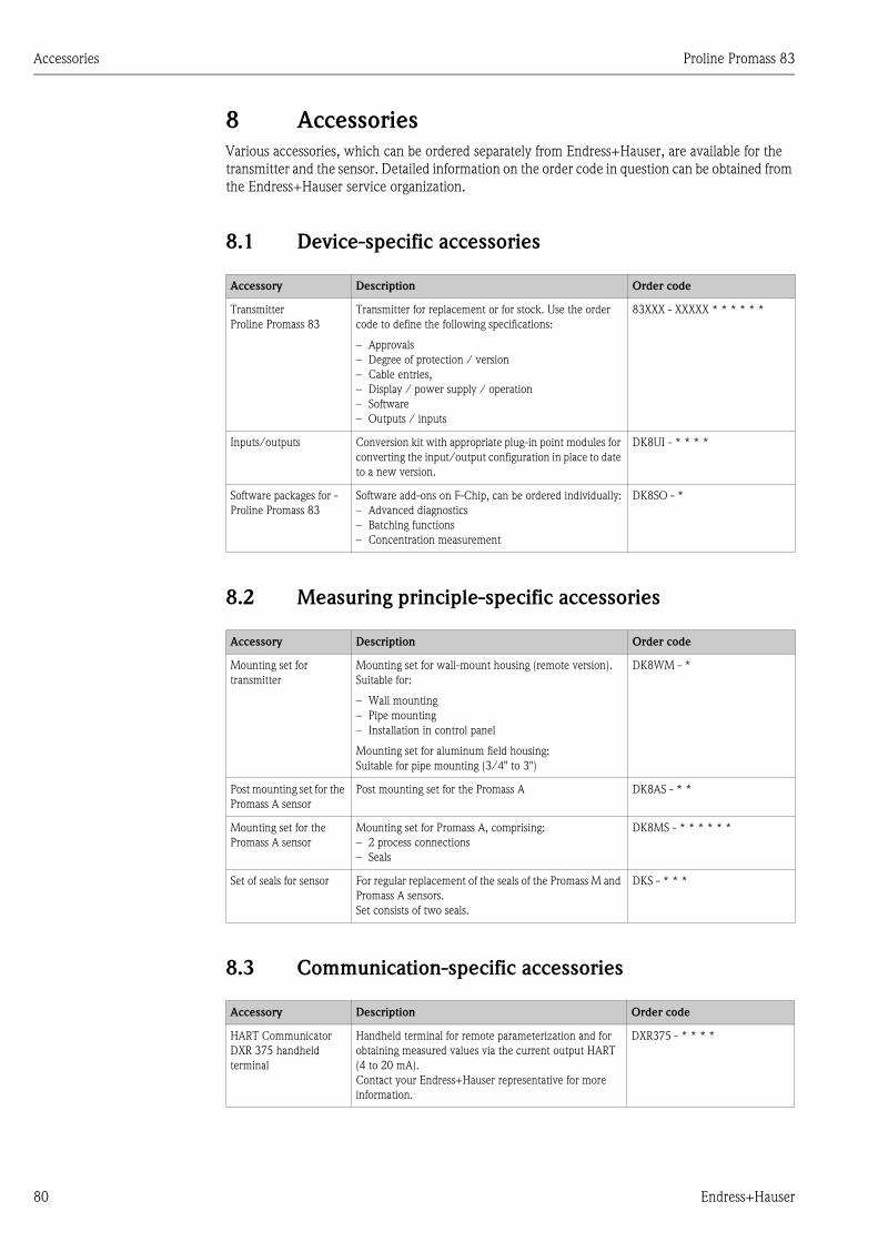
Accessories Proline Promass 83
80 Endress+Hauser
8 Accessories
Various accessories, which can be ordered separately from Endress+Hauser, are available for the
transmitter and the sensor. Detailed information on the order code in question can be obtained from
the Endress+Hauser service organization.
8.1 Device-specific accessories
8.2 Measuring principle-specific accessories
8.3 Communication-specific accessories
Accessory Description Order code
Transmitter
Proline Promass 83
Transmitter for replacement or for stock. Use the order
code to define the following specifications:
– Approvals
– Degree of protection / version
– Cable entries,
– Display / power supply / operation
– Software
– Outputs / inputs
83XXX - XXXXX * * * * * *
Inputs/outputs Conversion kit with appropriate plug-in point modules for
converting the input/output configuration in place to date
to a new version.
DK8UI - * * * *
Software packages for -
Proline Promass 83
Software add-ons on F-Chip, can be ordered individually:
– Advanced diagnostics
– Batching functions
– Concentration measurement
DK8SO - *
Accessory Description Order code
Mounting set for
transmitter
Mounting set for wall-mount housing (remote version).
Suitable for:
– Wall mounting
– Pipe mounting
– Installation in control panel
Mounting set for aluminum field housing:
Suitable for pipe mounting (3/4" to 3")
DK8WM - *
Post mounting set for the
Promass A sensor
Post mounting set for the Promass A DK8AS - * *
Mounting set for the
Promass A sensor
Mounting set for Promass A, comprising:
– 2 process connections
– Seals
DK8MS - * * * * * *
Set of seals for sensor For regular replacement of the seals of the Promass M and
Promass A sensors.
Set consists of two seals.
DKS - * * *
Accessory Description Order code
HART Communicator
DXR 375 handheld
terminal
Handheld terminal for remote parameterization and for
obtaining measured values via the current output HART
(4 to 20 mA).
Contact your Endress+Hauser representative for more
information.
DXR375 - * * * *
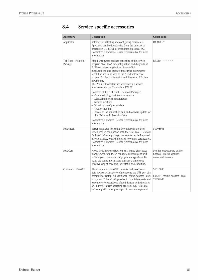
Proline Promass 83 Accessories
Endress+Hauser 81
8.4 Service-specific accessories
Accessory Description Order code
Applicator Software for selecting and configuring flowmeters.
Applicator can be downloaded from the Internet or
ordered on CD-ROM for installation on a local PC.
Contact your Endress+Hauser representative for more
information.
DXA80 - *
ToF Tool – Fieldtool
Package
Modular software package consisting of the service
program "ToF Tool" for configuration and diagnosis of
ToF level measuring devices (time-of-flight
measurement) and pressure measuring instruments
(evolution series) as well as the "Fieldtool" service
program for the configuration and diagnosis of Proline
flowmeters.
The Proline flowmeters are accessed via a service
interface or via the Commubox FXA291.
Contents of the "ToF Tool – Fieldtool Package":
– Commissioning, maintenance analysis
– Measuring device configuration
– Service functions
– Visualization of process data
– Troubleshooting
– Access to the verification data and software update for
the "Fieldcheck" flow simulator
Contact your Endress+Hauser representative for more
information.
DXS10 – * * * * *
Fieldcheck Tester/simulator for testing flowmeters in the field.
When used in conjunction with the "ToF Tool - Fieldtool
Package" software package, test results can be imported
into a database, printed and used for official certification.
Contact your Endress+Hauser representative for more
information.
50098801
FieldCare FieldCare is Endress+Hauser’s FDT-based plant asset
management tool. It can configure all intelligent field
units in your system and helps you manage them. By
using the status information, it is also a simple but
effective way of checking their status and condition.
See the product page on the
Endress+Hauser website:
www.endress.com
Commubox FXA291 The Commubox FXA291 connects Endress+Hauser
field devices with a Service Interface to the USB port of a
computer or laptop. An additional Proline Adapter Cabel
is required.This makes it possible to remotely operate and
execute service functions of field devices with the aid of
an Endress+Hauser operating program, e.g. FieldCare
software platform for plant-specific asset management.
51516983
FXA291 Proline Adapter Cable:
71032688
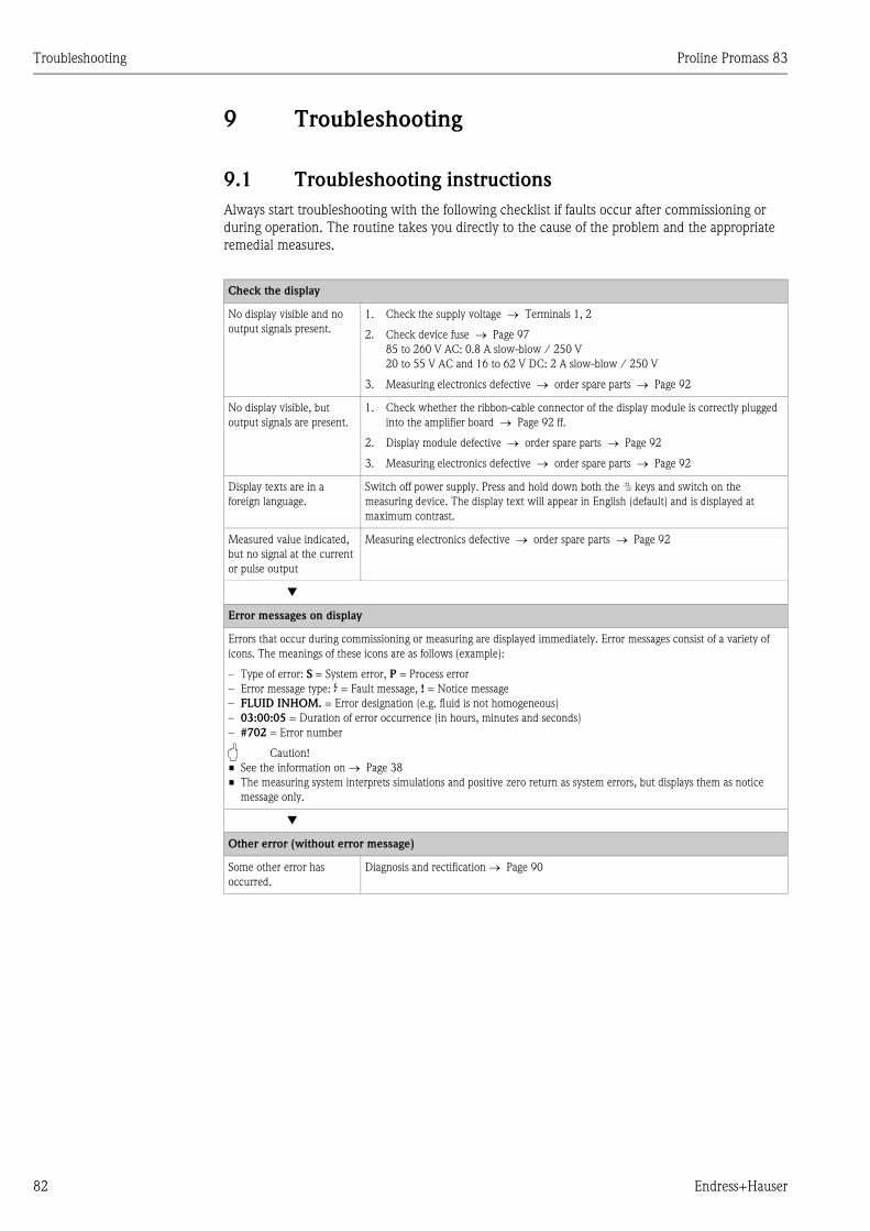
Troubleshooting Proline Promass 83
82 Endress+Hauser
9 Troubleshooting
9.1 Troubleshooting instructions
Always start troubleshooting with the following checklist if faults occur after commissioning or
during operation. The routine takes you directly to the cause of the problem and the appropriate
remedial measures.
Check the display
No display visible and no
output signals present.
1. Check the supply voltage → Terminals 1, 2
2. Check device fuse → Page 97
85 to 260 V AC: 0.8 A slow-blow / 250 V
20 to 55 V AC and 16 to 62 V DC: 2 A slow-blow / 250 V
3. Measuring electronics defective → order spare parts → Page 92
No display visible, but
output signals are present.
1. Check whether the ribbon-cable connector of the display module is correctly plugged
into the amplifier board → Page 92 ff.
2. Display module defective → order spare parts → Page 92
3. Measuring electronics defective → order spare parts → Page 92
Display texts are in a
foreign language.
Switch off power supply. Press and hold down both the P keys and switch on the
measuring device. The display text will appear in English (default) and is displayed at
maximum contrast.
Measured value indicated,
but no signal at the current
or pulse output
Measuring electronics defective → order spare parts → Page 92
▼
Error messages on display
Errors that occur during commissioning or measuring are displayed immediately. Error messages consist of a variety of
icons. The meanings of these icons are as follows (example):
– Type of error: S = System error, P = Process error
– Error message type: $ = Fault message, ! = Notice message
– FLUID INHOM. = Error designation (e.g. fluid is not homogeneous)
– 03:00:05 = Duration of error occurrence (in hours, minutes and seconds)
– #702 = Error number
" Caution!
• See the information on → Page 38
• The measuring system interprets simulations and positive zero return as system errors, but displays them as notice
message only.
▼
Other error (without error message)
Some other error has
occurred.
Diagnosis and rectification → Page 90
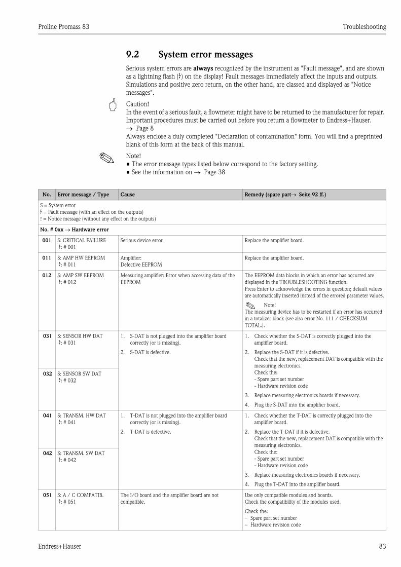
Proline Promass 83 Troubleshooting
Endress+Hauser 83
9.2 System error messages
Serious system errors are always recognized by the instrument as "Fault message", and are shown
as a lightning flash ($) on the display! Fault messages immediately affect the inputs and outputs.
Simulations and positive zero return, on the other hand, are classed and displayed as "Notice
messages".
" Caution!
In the event of a serious fault, a flowmeter might have to be returned to the manufacturer for repair.
Important procedures must be carried out before you return a flowmeter to Endress+Hauser.
→ Page 8
Always enclose a duly completed "Declaration of contamination" form. You will find a preprinted
blank of this form at the back of this manual.
! Note!
• The error message types listed below correspond to the factory setting.
• See the information on → Page 38
No. Error message / Type Cause Remedy (spare part→ Seite 92 ff.)
S = System error
$ = Fault message (with an effect on the outputs)
! = Notice message (without any effect on the outputs)
No. # 0xx → Hardware error
001 S: CRITICAL FAILURE
$: # 001
Serious device error Replace the amplifier board.
011 S: AMP HW EEPROM
$: # 011
Amplifier:
Defective EEPROM
Replace the amplifier board.
012 S: AMP SW EEPROM
$: # 012
Measuring amplifier: Error when accessing data of the
EEPROM
The EEPROM data blocks in which an error has occurred are
displayed in the TROUBLESHOOTING function.
Press Enter to acknowledge the errors in question; default values
are automatically inserted instead of the errored parameter values.
! Note!
The measuring device has to be restarted if an error has occurred
in a totalizer block (see also error No. 111 / CHECKSUM
TOTAL.).
031 S: SENSOR HW DAT
$: # 031
1. S-DAT is not plugged into the amplifier board
correctly (or is missing).
2. S-DAT is defective.
1. Check whether the S-DAT is correctly plugged into the
amplifier board.
2. Replace the S-DAT if it is defective.
Check that the new, replacement DAT is compatible with the
measuring electronics.
Check the:
- Spare part set number
- Hardware revision code
3. Replace measuring electronics boards if necessary.
4. Plug the S-DAT into the amplifier board.
032 S: SENSOR SW DAT
$: # 032
041 S: TRANSM. HW DAT
$: # 041
1. T-DAT is not plugged into the amplifier board
correctly (or is missing).
2. T-DAT is defective.
1. Check whether the T-DAT is correctly plugged into the
amplifier board.
2. Replace the T-DAT if it is defective.
Check that the new, replacement DAT is compatible with the
measuring electronics.
Check the:
- Spare part set number
- Hardware revision code
3. Replace measuring electronics boards if necessary.
4. Plug the T-DAT into the amplifier board.
042 S: TRANSM. SW DAT
$: # 042
051 S: A / C COMPATIB.
$: # 051
The I/O board and the amplifier board are not
compatible.
Use only compatible modules and boards.
Check the compatibility of the modules used.
Check the:
– Spare part set number
– Hardware revision code
Troubleshooting Proline Promass 83
84 Endress+Hauser
061 S: HW F-CHIP
$: # 061
F-Chip transmitter:
1. F-Chip is defective.
2. F-Chip is not plugged into the I/O board or is
missing.
1. Replace the F-Chip.
Accessories <Undefined Cross-Reference>
2. Plug the F-Chip into the I/O board.
No. # 1xx → Software error
111 S: CHECKSUM TOTAL.
$: # 111
Totalizer checksum error 1. Restart the measuring device
2. Replace the amplifier board if necessary.
121 S: A / C COMPATIB.
!: # 121
Due to different software versions, I/O board and
amplifier board are only partially compatible (possibly
restricted functionality).
! Note!
– This message is only listed in the error history.
– Nothing is displayed on the display.
Module with lower software version has either to be actualized by
ToF Tool - Fieldtool Package with the required software version
or the module has to be replaced.
No. # 2xx → Error in DAT / no communication
205 S: LOAD T-DAT
!: # 205
Transmitter DAT:
Data backup (downloading) to T-DAT failed, or error
when accessing (uploading) the calibration values stored
in the T-DAT.
1. Check whether the T-DAT is correctly plugged into the
amplifier board → Page 93 → Page 95
2. Replace the T-DAT if it is defective. Spare parts → Page 92
Before replacing the DAT, check that the new, replacement
DAT is compatible with the measuring electronics. Check
the:
– Spare part set number
– Hardware revision code
3. Replace measuring electronics boards if necessary.
206 S: SAVE T-DAT
!: # 206
251 S: COMMUNICATION I/
O
$: # 251
Internal communication fault on the amplifier board. Remove the amplifier board.
261 S: COMMUNICATION I/
O
$: # 261
No data reception between amplifier and I/O board or
faulty internal data transfer.
Check the BUS contacts
No. # 3xx → System limits exceeded
339
to
342
S: STACK CUR OUT n
$: # 339 to 342
The temporarily buffered flow portions (measuring mode
for pulsating flow) could not be cleared or output within
60 seconds.
1. Change the upper or lower limit setting, as applicable
2. Increase or reduce flow, as applicable
Recommendations in the event of fault category = FAULT
MESSAGE ($):– Configure the fault response of the output to ACTUAL VALUE,
so that the temporary buffer can be cleared. → Page 92
– Clear the temporary buffer by the measures described under
Item 1.
343
to
346
S: STACK FREQ. OUT n
$: # 343 to 346
347
to
350
S: STACK PULSE OUT n
!: # 347 to 350
The temporarily buffered flow portions (measuring mode
for pulsating flow) could not be cleared or output within
60 seconds.
1. Increase the setting for pulse weighting
2. Increase the max. pulse frequency, if the totalizer can handle
a higher number of pulses.
3. Increase or reduce flow, as applicable.
Recommendations in the event of fault category = FAULT
MESSAGE ($):– Configure the fault response of the output to ACTUAL
VALUE", so that the temporary buffer can be cleared.
→ Page 92
– Clear the temporary buffer by the measures described under
Item 1.
351
to
354
S: CURRENT RANGE n
!: # 351 to 354
Current output:
The actual value for the flow lies outside the set limits.
1. Change the upper or lower limit setting, as applicable
2. Increase or reduce flow, as applicable
355
to
358
S: FREQ. RANGE n
!: # 355 to 358
Frequency output:
The actual value for the flow lies outside the set limits.
1. Change the upper or lower limit setting, as applicable
2. Increase or reduce flow, as applicable
No. Error message / Type Cause Remedy (spare part→ Seite 92 ff.)
Proline Promass 83 Troubleshooting
Endress+Hauser 85
359
to
362
S: PULSE RANGE
!: # 359 to 362
Pulse output:
Pulse output frequency is out of range.
1. Increase the setting for pulse weighting
2. When selecting the pulse width, choose a value that can still
be processed by a connected counter (e.g. mechanical
counter, PLC etc.).
Determine the pulse width:
– Version 1: Enter the minimum duration that a pulse must
be present at the connected counter to ensure its
registration.
– Version 2: Enter the maximum (pulse) frequency as the
half "reciprocal value" that a pulse must be present at the
connected counter to ensure its registration.
Example:
The maximum input frequency of the connected counter is
10 Hz. The pulse width to be entered is:
a0004437
3. Reduce flow
363 S: CUR IN. RANGE
!: # 363
Current input:
The actual value for the current lies outside the set
limits.
1. Change set lower-range or upper-range value.
2. Check settings of the external sensor.
379
to
380
S: FREQ. LIM
$: # 379 to 380
The measuring tube oscillation frequency is outside the
permitted range.
Causes:
– Measuring tube damaged
– Sensor defective or damaged
Contact your E+H service organization.
381 S: FLUIDTEMP.MIN.
$: # 381
The temperature sensor on the measuring tube is likely
defective.
Check the following electrical connections before you contact
your E+H service organization:
– Verify that the sensor signal cable connector is correctly
plugged into the amplifier board.
– Remote version:
Check sensor and transmitter terminal connections No. 9
and 10. → Page 24
382 S: FLUIDTEMP.MAX.
$: # 382
383 S: CARR.TEMP.MIN
$: # 383
The temperature sensor on the carrier tube is likely
defective.
Check the following electrical connections before you contact
your E+H service organization:
– Verify that the sensor signal cable connector is correctly
plugged into the amplifier board.
– Remote version:
Check sensor and transmitter terminal connections No. 11
and 12. → Page 24
384 S: CARR.TEMP.MAX
$: # 384
385 S: INL.SENS.DEF.
$: # 385
One of the measuring tube exciter coils (inlet) is likely
defective.
Check the following electrical connections before you contact
your E+H service organization:
– Verify that the sensor signal cable connector is correctly
plugged into the amplifier board.
– Remote version:
Check sensor and transmitter terminal connections No. 4, 5, 6
and 7. → Page 24
386 S: OUTL.SENS.DEF.
$: # 386
One of the measuring tube exciter coils (outlet) is likely
defective.
387 S: SEN.ASY.EXCEED
$: # 387
Measuring pipe excitation coil is probably faulty.
388
to
390
S: AMP. FAULT
$: # 388 to 390
Amplifier error Contact your Endress+Hauser service organization.
No. # 5xx → Application error
501 S: SW.-UPDATE ACT.
!: # 501
New amplifier or communication (I/O module) software
version is loaded. Currently no other functions are
possible.
Wait until process is finished. The device will restart
automatically.
502 S: UP-/DOWNLOAD ACT.
!: # 502
Up- or downloading the device data via configuration
program. Currently no other functions are possible.
Wait until process is finished.
571 S: BATCH RUNNING
!: # 571
Batching is started and active (valves are open). No measures needed (during the batching process some other
functions may not be activated).
No. Error message / Type Cause Remedy (spare part→ Seite 92 ff.)
1
2.10 Hz= 50 ms
Troubleshooting Proline Promass 83
86 Endress+Hauser
572 S: BATCH HOLD
!: # 572
Batching has been interrupted (valves are closed). 1. Continue batching with command "GO ON".
2. Interrupt batching with "STOP" command.
586 S: OSC. AMP. LIMIT
$: # 586
The fluid properties do not allow a continuation of the
measurement.
Causes:
– Extremely high viscosity
– Process fluid is very inhomogeneous (gas or solid
content)
Change or improve process conditions.
587 S: TUBE OSC. NOT
$: # 587
Extreme process conditions exist. The measuring system
can therefore not be started.
Change or improve process conditions.
588 S: GAIN RED.IMPOS
$: # 588
Overdriving of the internal analog to digital converter.
Causes:
– Cavitation
– Extreme pressure pulses
– High gas flow velocity
A continuation of the measurement is no longer possible!
Change or improve process conditions, e.g. by reducing the flow
velocity.
No. # 6xx → Simulation mode active
601 S: POSITIVE ZERO
RETURN
!: # 601
Positive zero return active.
" Caution!
This message has the highest display priority.
Switch off positive zero return.
611
to
614
S: SIM. CURR. OUT. n
!: # 611 to 614
Simulation current output active.
621
to
624
S: SIM. FREQ. OUT n
!: # 621 to 624
Simulation frequency output active. Switch off simulation.
631
to
634
S: SIM. PULSE n
!: # 631 to 634
Simulation pulse output active. Switch off simulation.
641
to
644
S: SIM. STAT. OUT. n
!: # 641 to 644
Simulation status output active. Switch off simulation.
651
to
654
S: SIM. RELAY n
!: # 651 to 654
Simulation relay output active. Switch off simulation.
661
to
664
S: SIM. CURR. IN n
!: # 661 to 664
Simulation current input active. Switch off simulation.
671
to
674
S: SIM. STAT IN n
!: # 671 to 674
Simulation status input active. Switch off simulation.
691 S: SIM. FAILSAFE
!: # 691
Simulation of response to error (outputs) active. Switch off simulation.
692 S: SIM. MEASURAND
!: # 692
Simulation of measuring variables (e.g. mass flow). Switch off simulation.
698 S: DEV. TEST AKT.
!: # 698
The measuring device is being checked on site via the
test and simulation device.
−
No. # 8xx → Other error messages with software options (Coriolis flowmeter)
800 S: M. FL. DEV. LIMIT
!: # 800
Advanced Diagnostics:
The mass flow is outside the limit value, set in the
corresponding diagnosis function.
−
801 S: DENS. DEV. LIMIT
!: # 801
Advanced Diagnostics:
The density is outside the limit value, set in the
corresponding diagnosis function.
−
No. Error message / Type Cause Remedy (spare part→ Seite 92 ff.)
Proline Promass 83 Troubleshooting
Endress+Hauser 87
802 S: REF. D. DEV. LIM.
!: # 802
Advanced Diagnostics:
The reference density is outside the limit value, set in the
corresponding diagnosis function.
−
803 S: TEMP. DEV. LIMIT
!: # 803
Advanced Diagnostics:
The temperature is outside the limit value, set in the
corresponding diagnosis function.
−
804 S: T. DAMP DEV. LIM
!: # 804
Advanced Diagnostics:
The tube damping is outside the limit value, set in the
corresponding diagnosis function.
−
805 S: E.D. SEN. DEV. LIM
!: # 805
Advanced Diagnostics:
The electrodynamic sensor is outside the limit value, set
in the corresponding diagnosis function.
−
806 S: F. FLUCT. DEV. LI
!: # 806
Advanced Diagnostics:
The fluctuation of the operating frequency is outside the
limit value set in the corresponding diagnosis functions.
−
807 S: TD FLUCT. DEV. LI
!: # 807
Advanced Diagnostics:
The fluctuation of the pipe damping is outside the limit
value set in the corresponding diagnosis functions.
−
No. Error message / Type Cause Remedy (spare part→ Seite 92 ff.)
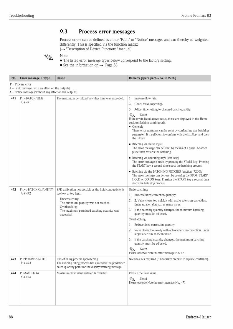
Troubleshooting Proline Promass 83
88 Endress+Hauser
9.3 Process error messages
Process errors can be defined as either "Fault" or "Notice" messages and can thereby be weighted
differently. This is specified via the function matrix
(→ "Description of Device Functions" manual).
! Note!
• The listed error message types below correspond to the factory setting.
• See the information on → Page 38
No. Error message / Type Cause Remedy (spare part→ Seite 92 ff.)
P = Process error
$ = Fault message (with an effect on the outputs)
! = Notice message (without any effect on the outputs)
471 P: > BATCH TIME
$: # 471
The maximum permitted batching time was exceeded. 1. Increase flow rate.
2. Check valve (opening).
3. Adjust time setting to changed batch quantity.
! Note!
If the errors listed above occur, these are displayed in the Home
position flashing continuously.
• General:
These error messages can be reset by configuring any batching
parameter. It is sufficient to confirm with the OS key and then
the F key.
• Batching via status input:
The error message can be reset by means of a pulse. Another
pulse then restarts the batching.
• Batching via operating keys (soft keys)
The error message is reset by pressing the START key. Pressing
the START key a second time starts the batching process.
• Batching via the BATCHING PROCESS function (7260):
The error message can be reset by pressing the STOP, START,
HOLD or GO ON keys. Pressing the START key a second time
starts the batching process.
472 P: >< BATCH QUANTITY
$: # 472
EPD calibration not possible as the fluid conductivity is
too low or too high.
– Underbatching:
The minimum quantity was not reached.
– Overbatching:
The maximum permitted batching quantity was
exceeded.
Underbatching:
1. Increase fixed correction quantity.
2. 2. Valve closes too quickly with active after run correction.
Enter smaller after run as mean value.
3. If the batching quantity changes, the minimum batching
quantity must be adjusted.
Overbatching:
1. Reduce fixed correction quantity.
2. Valve closes too slowly with active after run correction. Enter
larger after run as mean value.
3. If the batching quantity changes, the maximum batching
quantity must be adjusted.
! Note!
Please observe Note in error message No. 471
473 P: PROGRESS NOTE
$: # 473
End of filling process approaching.
The running filling process has exceeded the predefined
batch quantity point for the display warning message.
No measures required (if necessary prepare to replace container).
474 P: MAX. FLOW
!: # 474
Maximum flow value entered is overshot. Reduce the flow value.
! Note!
Please observe Note in error message No. 471
Proline Promass 83 Troubleshooting
Endress+Hauser 89
No. # 7xx → Other process errors)
700 P: EMPTY PIPE
!: # 700
The process fluid density is outside the upper or lower
limit values set in the EPD function
Causes:
– Air in the measuring tube
– Partly filled measuring tube
1. Ensure that there is no gas content in the process liquid.
2. Adapt the values in the EPD function to the current process
conditions.
701 P: EXC. CURR. LIM
!: # 701
The maximum current value for the measuring tube
exciter coils has been reached, since certain process fluid
characteristics are extreme, e.g. high gas or solid
content.
The instrument continues to work correctly.
In particular with outgassing fluids and/or increased gas content,
the following measures are recommended to increase system
pressure:
1. Install the instrument at the outlet side of a pump.
2. Install the instrument at the lowest point of an ascending
pipeline.
3. Install a flow restriction, e.g. reducer or orifice plate,
downstream from the instrument.
702 P: FLUID INHOM.
!: # 702
Frequency control is not stable, due to inhomogeneous
process fluid, e.g. gas or solid content.
703 P: NOISE LIM. CH0
!: # 703
Overdriving of the internal analog to digital converter.
Causes:
– Cavitation
– Extreme pressure pulses
– High gas flow velocity
A continuation of the measurement is still possible!
Change or improve process conditions, e.g. by reducing the flow
velocity.
704 P: NOISE LIM. CH1
!: # 704
705 P: FLOW LIMIT
$: # 705
The mass flow is too high. The electronics' measuring
range will be exceeded.
Reduce flow
731 P: ADJ. ZERO FAIL
!: # 731
The zero point adjustment is not possible or has been
canceled.
Make sure that zero point adjustment is carried out at "zero flow"
only (v = 0 m/s). → Page 75
No. Error message / Type Cause Remedy (spare part→ Seite 92 ff.)
Troubleshooting Proline Promass 83
90 Endress+Hauser
9.4 Process errors without messages
Symptoms Rectification
Comment:
You may have to change or correct certain settings of the function matrix in order to rectify faults. The functions outlined below, such as DISPLAY DAMPING, for
example, are described in detail in the "Description of Device Functions" manual.
Measured value reading fluctuates even
though flow is steady.
1. Check the fluid for presence of gas bubbles.
2. TIME CONSTANT function → increase value (→ OUTPUTS / CURRENT OUTPUT / CONFIGURATION)
3. DISPLAY DAMPING function → increase value (→ USER INTERFACE / CONTROL / BASIC CONFIGURATION)
Flow values are negative, even though
the fluid is flowing forwards through
the pipe.
Change the INSTALLATION DIR. SENSOR function accordingly
Measured-value reading or measured-
value output pulsates or fluctuates, e.g.
because of reciprocating pump,
peristaltic pump, diaphragm pump or
pump with similar delivery
characteristic.
Run the "Pulsating Flow" Quick Setup. → Page 55
If the problem persists despite these measures, a pulsation damper will have to be installed between pump and measuring
device.
There are differences between the
flowmeter's internal totalizer and the
external metering device.
This symptom is due primarily to backflow in the piping, because the pulse output cannot subtract in the "STANDARD" or
"SYMMETRY" measuring modes.
The problem can be solved as follows:
Allow for flow in both directions. Set the MEASURING MODE function to "Pulsating Flow" for the pulse output in
question.
Measured value reading shown on
display, even though the fluid is at a
standstill and the measuring tube is full.
1. Check the fluid for presence of gas bubbles.
2. Activate the ON-VAL. LF-CUTOFF function, i.e. enter or increase the value for the low flow cutoff
(→ BASIC FUNCTION / PROCESS PARAMETER / CONFIGURATION).
The error cannot be eliminated or
another error pattern is present.
In instances of this nature, contact your
E+H service organization.
The following solutions are possible:
Request the services of an Endress+Hauser service technician
If you request the services of a service technician, please be ready with the following information:
– Brief error description
– Nameplate specifications: order code and serial number → Page 9 ff.
Return the devices to Endress+Hauser
Procedures must be carried out before you return a flowmeter to Endress+Hauser for repair or calibration. Please see
Page 8.
Always enclose a duly completed "Declaration of contamination" form with the flowmeter. You will find a master copy of
the Dangerous Goods Sheet at the back of these Operating Instructions.
Replace the transmitter electronics
Parts of the measuring electronics defective → order spare part → Page 92
Proline Promass 83 Troubleshooting
Endress+Hauser 91
9.5 Response of outputs to errors
! Note!
The failsafe mode of totalizers, current, pulse and frequency outputs can be customized by means
of various functions in the function matrix. You will find detailed information on these procedures
in the "Description of Device Functions" manual.
You can use positive zero return to set the signals of the current, pulse and status outputs to their
fallback value, for example when measuring has to be interrupted while a pipe is being cleaned. This
function takes priority over all other device functions. Simulations, for example, are suppressed.
Failsafe mode of outputs and totalizers
Process/system error is present Positive zero return is activated
" Caution!
System or process errors defined as "Notice messages" have no effect whatsoever on the inputs and outputs. See the information on Page 38 ff.
Current output MIN. CURRENT
The current output will be set to the lower value of the signal on alarm level depending on
the setting selected in the CURRENT SPAN (see the "Description of Device Functions"
manual).
MAX. CURRENT
The current output will be set to the higher value of the signal on alarm level depending on
the setting selected in the CURRENT SPAN (see the "Description of Device Functions"
manual).
HOLD VALUE
Measured value display on the basis of the last saved value preceding occurrence of the
fault.
ACTUAL VALUE
Measured value display on the basis of the current flow measurement. The fault is ignored.
Output signal corresponds to "zero flow"
Pulse output FALLBACK VALUE
Signal output → no pulses
HOLD VALUE
Last valid value (preceding occurrence of the fault) is output.
ACTUAL VALUE
Fault is ignored, i.e. normal measured value output on the basis of ongoing flow
measurement.
Output signal corresponds to "zero flow"
Frequency output FALLBACK VALUE
Signal output → 0 Hz
FAILSAFE VALUE
Output of the frequency specified in the FAILSAFE VALUE function.
HOLD VALUE
Last valid value (preceding occurrence of the fault) is output.
ACTUAL VALUE
Fault is ignored, i.e. normal measured value output on the basis of ongoing flow
measurement.
Output signal corresponds to "zero flow"
Totalizer STOP
The totalizers are paused until the error is rectified.
ACTUAL VALUE
The fault is ignored. The totalizer continues to count in accordance with the current flow
value.
HOLD VALUE
The totalizers continue to count the flow in accordance with the last valid flow value
(before the error occurred).
Totalizer stops
Relay output In event of fault or power supply failure: relay → de-energized
The "Description of Device Functions" manual contains detailed information on relay
switching response for various configurations such as error message, flow direction, EPD,
full scale value, etc.
No effect on the relay output
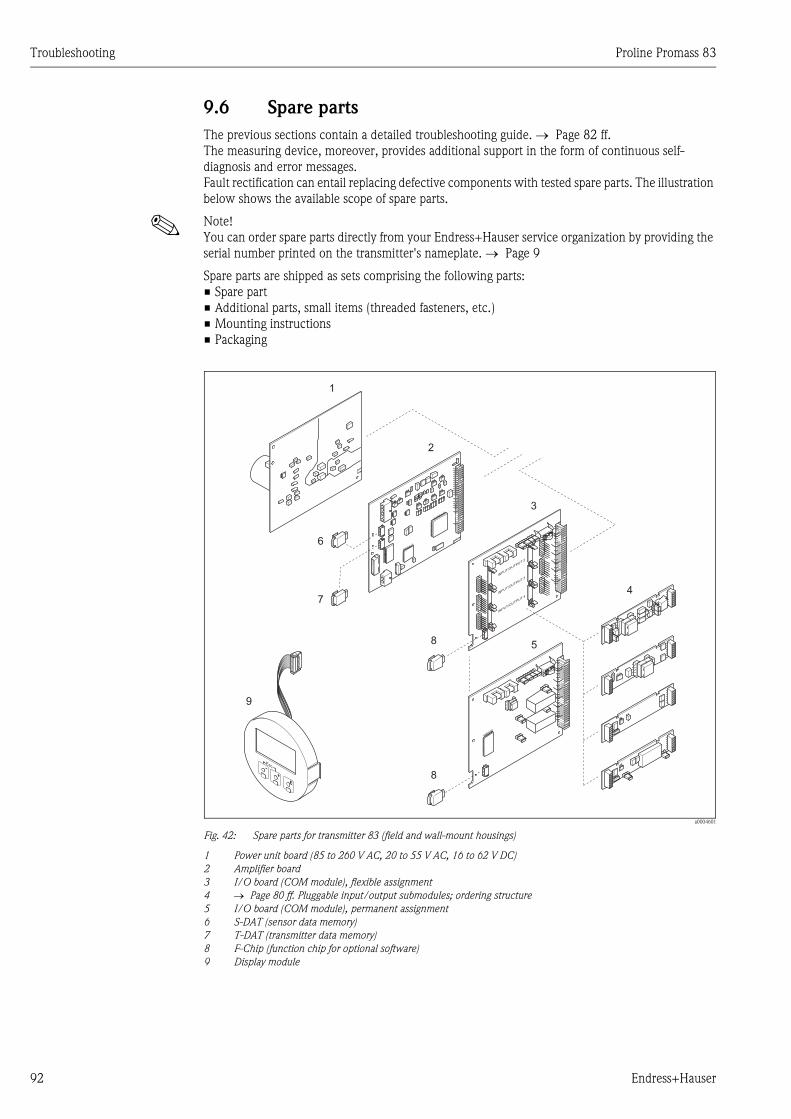
Troubleshooting Proline Promass 83
92 Endress+Hauser
9.6 Spare parts
The previous sections contain a detailed troubleshooting guide. → Page 82 ff.
The measuring device, moreover, provides additional support in the form of continuous self-
diagnosis and error messages.
Fault rectification can entail replacing defective components with tested spare parts. The illustration
below shows the available scope of spare parts.
! Note!
You can order spare parts directly from your Endress+Hauser service organization by providing the
serial number printed on the transmitter's nameplate. → Page 9
Spare parts are shipped as sets comprising the following parts:
• Spare part
• Additional parts, small items (threaded fasteners, etc.)
• Mounting instructions
• Packaging
a0004601
Fig. 42: Spare parts for transmitter 83 (field and wall-mount housings)
1 Power unit board (85 to 260 V AC, 20 to 55 V AC, 16 to 62 V DC)
2 Amplifier board
3 I/O board (COM module), flexible assignment
4 → Page 80 ff. Pluggable input/output submodules; ordering structure
5 I/O board (COM module), permanent assignment
6 S-DAT (sensor data memory)
7 T-DAT (transmitter data memory)
8 F-Chip (function chip for optional software)
9 Display module
1
2
3
4
9
6
7
8
8
INPUT/O
UTPUT2
INPUT/O
UTPUT3
INPUT/O
UTPUT4
5
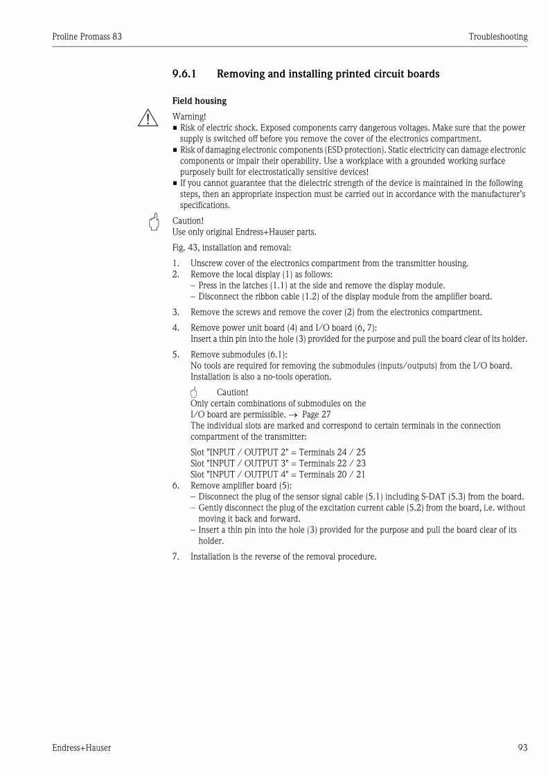
Proline Promass 83 Troubleshooting
Endress+Hauser 93
9.6.1 Removing and installing printed circuit boards
Field housing
# Warning!
• Risk of electric shock. Exposed components carry dangerous voltages. Make sure that the power
supply is switched off before you remove the cover of the electronics compartment.
• Risk of damaging electronic components (ESD protection). Static electricity can damage electronic
components or impair their operability. Use a workplace with a grounded working surface
purposely built for electrostatically sensitive devices!
• If you cannot guarantee that the dielectric strength of the device is maintained in the following
steps, then an appropriate inspection must be carried out in accordance with the manufacturer’s
specifications.
" Caution!
Use only original Endress+Hauser parts.
Fig. 43, installation and removal:
1. Unscrew cover of the electronics compartment from the transmitter housing.
2. Remove the local display (1) as follows:
– Press in the latches (1.1) at the side and remove the display module.
– Disconnect the ribbon cable (1.2) of the display module from the amplifier board.
3. Remove the screws and remove the cover (2) from the electronics compartment.
4. Remove power unit board (4) and I/O board (6, 7):
Insert a thin pin into the hole (3) provided for the purpose and pull the board clear of its holder.
5. Remove submodules (6.1):
No tools are required for removing the submodules (inputs/outputs) from the I/O board.
Installation is also a no-tools operation.
" Caution!
Only certain combinations of submodules on the
I/O board are permissible. → Page 27
The individual slots are marked and correspond to certain terminals in the connection
compartment of the transmitter:
Slot "INPUT / OUTPUT 2" = Terminals 24 / 25
Slot "INPUT / OUTPUT 3" = Terminals 22 / 23
Slot "INPUT / OUTPUT 4" = Terminals 20 / 21
6. Remove amplifier board (5):
– Disconnect the plug of the sensor signal cable (5.1) including S-DAT (5.3) from the board.
– Gently disconnect the plug of the excitation current cable (5.2) from the board, i.e. without
moving it back and forward.
– Insert a thin pin into the hole (3) provided for the purpose and pull the board clear of its
holder.
7. Installation is the reverse of the removal procedure.
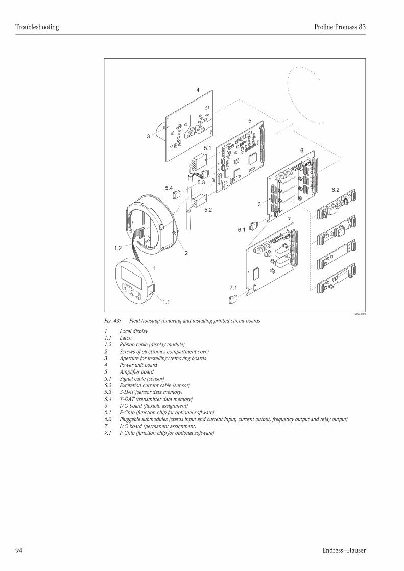
Troubleshooting Proline Promass 83
94 Endress+Hauser
a0004600
Fig. 43: Field housing: removing and installing printed circuit boards
1 Local display
1.1 Latch
1.2 Ribbon cable (display module)
2 Screws of electronics compartment cover
3 Aperture for installing/removing boards
4 Power unit board
5 Amplifier board
5.1 Signal cable (sensor)
5.2 Excitation current cable (sensor)
5.3 S-DAT (sensor data memory)
5.4 T-DAT (transmitter data memory)
6 I/O board (flexible assignment)
6.1 F-Chip (function chip for optional software)
6.2 Pluggable submodules (status input and current input, current output, frequency output and relay output)
7 I/O board (permanent assignment)
7.1 F-Chip (function chip for optional software)
4
5
6
6.2
3
3
3
2
1
1.2
5.1
5.35.4
5.2
1.1
INPUT/O
UTPUT2
INPUT/O
UTPUT3
INPUT/O
UTPUT4
6.1
7
7.1
Proline Promass 83 Troubleshooting
Endress+Hauser 95
Wall-mount housing
# Warning!
• Risk of electric shock. Exposed components carry dangerous voltages. Make sure that the power
supply is switched off before you remove the cover of the electronics compartment.
• Risk of damaging electronic components (ESD protection). Static electricity can damage electronic
components or impair their operability. Use a workplace with a grounded working surface
purposely built for electrostatically sensitive devices!
• If you cannot guarantee that the dielectric strength of the device is maintained in the following
steps, then an appropriate inspection must be carried out in accordance with the manufacturer’s
specifications.
" Caution!
Use only original Endress+Hauser parts.
Fig. 44, installation and removal:
1. Remove the screws and open the hinged cover (1) of the housing.
2. Loosen the screws securing the electronics module (2). Then push up electronics module and
pull it as far as possible out of the wall-mount housing.
3. Disconnect the following cable plugs from amplifier board (7):
– Sensor signal cable plug (7.1) including S-DAT (7.3)
– Unplug excitation current cable (7.2). Gently disconnect the plug, i.e. without moving it
back and forward.
– Ribbon cable plug (3) of the display module.
4. Remove the cover (4) from the electronics compartment by loosening the screws.
5. Remove the boards (6, 7, 8, 9):
Insert a thin pin into the hole (5) provided for the purpose and pull the board clear of its holder.
6. Remove submodules (8.1):
No tools are required for removing the submodules (inputs/outputs) from the I/O board.
Installation is also a no-tools operation.
" Caution!
Only certain combinations of submodules on the I/O board are permissible. → Page 27
The individual slots are marked and correspond to certain terminals in the connection
compartment of the transmitter:
Slot "INPUT / OUTPUT 2" = Terminals 24 / 25
Slot "INPUT / OUTPUT 3" = Terminals 22 / 23
Slot "INPUT / OUTPUT 4" = Terminals 20 / 21
7. Installation is the reverse of the removal procedure.
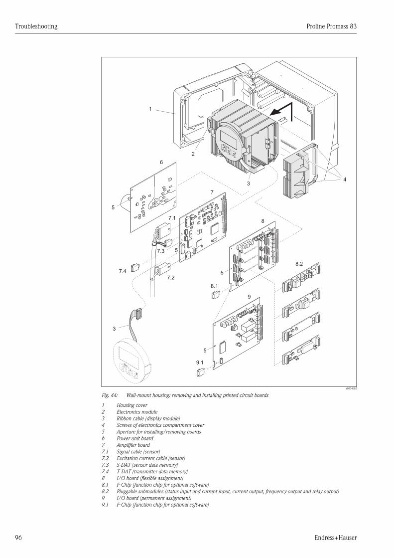
Troubleshooting Proline Promass 83
96 Endress+Hauser
a0004602
Fig. 44: Wall-mount housing: removing and installing printed circuit boards
1 Housing cover
2 Electronics module
3 Ribbon cable (display module)
4 Screws of electronics compartment cover
5 Aperture for installing/removing boards
6 Power unit board
7 Amplifier board
7.1 Signal cable (sensor)
7.2 Excitation current cable (sensor)
7.3 S-DAT (sensor data memory)
7.4 T-DAT (transmitter data memory)
8 I/O board (flexible assignment)
8.1 F-Chip (function chip for optional software)
8.2 Pluggable submodules (status input and current input, current output, frequency output and relay output)
9 I/O board (permanent assignment)
9.1 F-Chip (function chip for optional software)
34
1
2
3
6
7
8
8.2
9
5
5
7.1
7.3
7.4
7.2
INPUT/O
UTPUT2
INPUT/O
UTPUT3
INPUT/O
UTPUT4
8.1
5
5
9.1
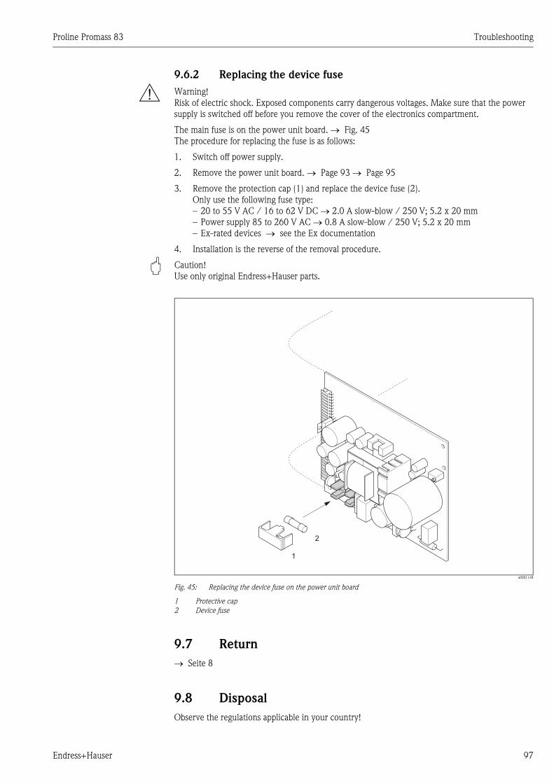
Proline Promass 83 Troubleshooting
Endress+Hauser 97
9.6.2 Replacing the device fuse
# Warning!
Risk of electric shock. Exposed components carry dangerous voltages. Make sure that the power
supply is switched off before you remove the cover of the electronics compartment.
The main fuse is on the power unit board. → Fig. 45
The procedure for replacing the fuse is as follows:
1. Switch off power supply.
2. Remove the power unit board. → Page 93 → Page 95
3. Remove the protection cap (1) and replace the device fuse (2).
Only use the following fuse type:
– 20 to 55 V AC / 16 to 62 V DC → 2.0 A slow-blow / 250 V; 5.2 x 20 mm
– Power supply 85 to 260 V AC → 0.8 A slow-blow / 250 V; 5.2 x 20 mm
– Ex-rated devices → see the Ex documentation
4. Installation is the reverse of the removal procedure.
" Caution!
Use only original Endress+Hauser parts.
a0001148
Fig. 45: Replacing the device fuse on the power unit board
1 Protective cap
2 Device fuse
9.7 Return
→ Seite 8
9.8 Disposal
Observe the regulations applicable in your country!
1
2
Troubleshooting Proline Promass 83
98 Endress+Hauser
9.9 Software history
! Note!
Up or downloading a software version normally requires a special service software.
Date Software version Changes to software Documentation
12.2006 2.02.00 New Sensor:
Promass S
Promass P
BA059D/06/en/12.06
71036077
11.2005 2.01.XX Software expansion:
– Promass I DN80, DN50FB
– Additional functionalities for "Advanced
Diagnosis"
– Additional functionalities for "Batching"
– General instrument functions
BA059D/06/en/12.05
71008485
11.2004 2.00.XX Software expansion:
– Assignment of reference density to the
current input
– HART Command #3 extends functionalities
for F-Chip (e.g. density functions)
– New sensor DN 250
– Chinese language package (English and
Chinese contents)
New functionalities:
– Empty pipe detection via exciting current
(EPD EXC.CURR. (6426))
– Extension with batching option:
MAX.FLOW (7244) → Maximum flow
exceeded during batching
BATCH TIME (7283) → Dosing time
exceeded
– DEVICE SOFTWARE (8100) → Device
software displayed
(NAMUR Recommendation 53)
– REMOVE SW OPTION (8006) → remove
F-CHIP options
BA059D/06/en/11.04
50098469
10.2003 Amplifier:
1.06.XX
Communication module:
1.03.XX
Software expansion:
– Language groups
– Flow direction pulse output selectable
– Adjustments to Fieldcheck and Simubox
– Concentration measurement with 4 data
records
– Viscosity measurement with temperature
compensation
– Acquisition start via status input for
advanced diagnostics
– SIL 2
New functionalities:
– Operation hours counter
– Intensity of background illumination
adjustable
– Simulation pulse output
– Counter for access code
– Current input
– Simulation pulse output
Compatible with:
– ToF-Tool FieldTool Package
(the latest SW version can be downloaded
under: www.tof-fieldtool.endress.com)
– HART Communicator DXR 375
With Device Rev. 5, DD Rev. 1
BA059D/06/en/10.03
50098469
Proline Promass 83 Troubleshooting
Endress+Hauser 99
03.2003 Amplifier:
1.05.XX
Communication module:
1.02.XX
Software adjustment BA059D/06/en/03.03
50098469
08.2002 Amplifier:
1.04.XX
Communication module:
1.02.XX
Software expansion:
– Promass H
– Promass E
BA059D/06/en/08.02
50098469
06.2001 Amplifier:
1.02.XX
Communication module:
1.02.XX
Software expansion:
– General instrument functions
– "Batching" software function
– "Pulse width" software function
– "Concentration measurement" software
function
– "Advanced Diagnostics" software function
– HART operating via Universal Commands
and Common Practice Commands
BA059D/06/en/06.01
50098469
03.2001 Amplifier:
1.01.XX
Communication module:
1.01.XX
Software adjustment BA059D/06/en/11.00
50098469
11.2000 Amplifier:
1.00.XX
Communication module:
1.01.XX
Original software
Compatible with:
– Fieldtool
– HART Communicator DXR 275
(as of OS 4.6) with Rev. 1, DD 1.
BA059D/06/en/11.00
50098469
Date Software version Changes to software Documentation
Technical data Proline Promass 83
100 Endress+Hauser
10 Technical data
10.1 Technical data at a glance
10.1.1 Applications
→ Seite 7
10.1.2 Function and system design
Measuring principle Mass flow measurement by the Coriolis principle
Measuring system → Seite 9
10.1.3 Input
Measured variable • Mass flow (proportional to the phase difference between two sensors mounted on the measuring
tube to register a phase shift in the oscillation)
• Fluid density (proportional to resonance frequency of the measuring tube)
• Fluid temperature (measured with temperature sensors)
Measuring range Measuring ranges for liquids (Promass F, M):
Measuring ranges for liquids (Promass E, H, S, P):
DN Range for full scale values (liquids) gmin(F) to gmax(F)
8 3/8" 0 to 2000 kg/h 0 to 73.5 lb/min
15 1/2" 0 to 6500 kg/h 0 to 238 lb/min
25 1" 0 to 18000 kg/h 0 to 660 lb/min
40 1 ½" 0 to 45000 kg/h 0 to 1650 lb/min
50 2" 0 to 70000 kg/h 0 to 2570 lb/min
80 3" 0 to 180000 kg/h 0 to 6600 lb/min
100* 4"* 0 to 350000 kg/h 0 to 12860 lb/min
150* 6"* 0 to 800000 kg/h 0 to 29400 lb/min
250* 10"* 0 to 2200000 kg/h 0 to 80860 lb/min
*) only Promass F
DN Range for full scale values (liquids) gmin(F) to gmax(F)
8 3/8" 0 to 2000 kg/h 0 to 73.5 lb/min
15 1/2" 0 to 6500 kg/h 0 to 238 lb/min
25 1" 0 to 18000 kg/h 0 to 660 lb/min
40 1 ½" 0 to 45000 kg/h 0 to 1650 lb/min
50 2" 0 to 70000 kg/h 0 to 2570 lb/min
Proline Promass 83 Technical data
Endress+Hauser 101
Measuring ranges for liquids (Promass A):
Measuring ranges for liquids (Promass I):
Measuring ranges for gases (except Promass H)
The full scale values depend on the density of the gas. Use the formula below to calculate the full
scale values:
gmax(G) = gmax(F) ⋅ ρ(G) : x[kg/m3 (lb/ft3)]
gmax(G) = Max. full scale value for gas [kg/h (lb/min)]
gmax(F) = Max. full scale value for liquid [kg/h (lb/min)]
ρ(G) = Gas density in [kg/m3 (lb/ft3)] for process conditions
x = 160 (Promass F DN 8 to 100 (3/8" to 4"), M, I)
x = 250 (Promass F DN 150 to 250 (6" to 10" ))
x = 225 (Promass E);
x = 32 (Promass A)
Here, gmax(G) can never be greater than gmax(F)
Calculation example for gas:
• Sensor type: Promass F, DN 50
• Gas: air with a density of 60.3 kg/m3 (at 20 °C and 50 bar)
• Measuring range: 70000 kg/h
• x = 160 (for Promass F DN 50)
Max. possible full scale value:
mmax(G) = mmin(F) ⋅ ρ(G) : x [kg/m3] = 70000 kg/h ⋅ 60.3 kg/m3 : 160 kg/m3 = 26400 kg/h
Recommended full scale values
See → Page 112 ff. ("Limiting flow")
Operable flow range Greater than 1000 : 1. Flows above the preset full scale value do not overload the amplifier, i.e.
totalizer values are registered correctly.
DN Range for full scale values (liquids) gmin(F) to gmax(F)
1 1/24" 0 to 20 kg/h 0 to 0.7 lb/min
2 1/12" 0 to 100 kg/h 0 to 3.7 lb/min
4 1/8" 0 to 450 kg/h 0 to 16.5 lb/min
DN Range for full scale values (liquids) gmin(F) to gmax(F)
8 3/8" 0 to 2000 kg/h 0 to 73.5 lb/min
15 1/2" 0 to 6500 kg/h 0 to 238 lb/min
15 FB 1/2" FB 0 to 18000 kg/h 0 to 660 lb/min
25 1" 0 to 18000 kg/h 0 to 660 lb/min
25 FB 1" FB 0 to 45000 kg/h 0 to 1650 lb/min
40 1 ½" 0 to 45000 kg/h 0 to 1650 lb/min
40 FB 1 ½" FB 0 to 70000 kg/h 0 to 2570 lb/min
50 2" 0 to 70000 kg/h 0 to 2570 lb/min
50 FB 2" FB 0 to 180000 kg/h 0 to 6600 lb/min
80 3" 0 to 180000 kg/h 0 to 6600 lb/min
FB = Full bore versions of Promass I
Technical data Proline Promass 83
102 Endress+Hauser
Input signal Status input (auxiliary input):
U = 3 to 30 V DC, Ri = 5 kΩ, galvanically isolated.
Configurable for: totalizer reset, positive zero return, error message reset, start zero point
adjustment, batching start/stop (optional)
Current input:
Active/passive selectable, galvanically isolated, resolution: 2 μA
• Active: 4 to 20 mA, RL < 700 Ω, Uout = 24 V DC, short-circuit proof
• Passive: 0/4 to 20 mA, Ri = 150 Ω, Umax = 30 V DC
10.1.4 Output
Output signal Current output:
Active/passive selectable, galvanically isolated, time constant selectable (0.05 to 100 s), full scale
value selectable, temperature coefficient: typically 0.005% of full scale value/°C, resolution: 0.5 μA
• Active: 0/4 to 20 mA, RL < 700 Ω (for HART: RL ≥ 250 Ω)
• Passive: 4 to 20 mA; supply voltage US 18 to 30 V DC; Ri ≥ 150 Ω
Pulse/frequency output:
Active/passive selectable, galvanically isolated
• Active: 24 V DC, 25 mA (max. 250 mA during 20 ms), RL > 100 Ω• passive: open collector, 30 V DC, 250 mA
• Frequency output: full scale frequency 2 to 10000 Hz (fmax = 12500 Hz), on/off ratio 1:1, pulse
width max. 2 s
• Pulse output: pulse value and pulse polarity selectable, pulse width configurable (0.05 to
2000 ms)
Signal on alarm Current output:
Failsafe mode selectable (for example, according to NAMUR Recommendation NE 43)
Pulse/frequency output:
Failsafe mode selectable
Relay output:
De-energized in the event of fault or power supply failure
Load See "Output signal"
Switching output Relay output:
Normally closed (NC or break)
or normally open (NO or make) contacts available (default: relay 1 = NO, relay 2 = NC), max. 30
V / 0.5 A AC; 60 V / 0.1 A DC, galvanically isolated.
Configurable for: error messages, Empty Pipe Detection (EPD), flow direction, limit values, batching
valve 1 and 2 (optional).
Low flow cutoff Switch points for low flow cutoff are selectable.
Galvanic isolation All circuits for inputs, outputs, and power supply are galvanically isolated from each other.
Proline Promass 83 Technical data
Endress+Hauser 103
10.1.5 Power supply
Electrical connections → Page 24 ff.
Supply voltage 85 to 260 V AC, 45 to 65 Hz
20 to 55 V AC, 45 to 65 Hz
16 to 62 V DC
Cable entry Power supply and signal cables (inputs/outputs):
• Cable entry M20 x 1.5 (8 to 12 mm)
• Threads for cable entries, 1/2" NPT, G 1/2"
Connecting cable for remote version:
• Cable entry M20 x 1.5 (8 to 12 mm)
• Threads for cable entries, 1/2" NPT, G 1/2"
Cable specifications (remote
version)
→ Page 25
Power consumption AC: <15 VA (including sensor)
DC: <15 W (including sensor)
Switch-on current:
• max. 13.5 A (< 50 ms) at 24 V DC
• max. 3 A (< 5 ms) at 260 V AC
Power supply failure Lasting min. 1 power cycle:
• EEPROM and T-DAT save measuring system data if power supply fails.
• HistoROM/S-DAT: exchangeable data storage chip which stores the data of the sensor (nominal
diameter, serial number, calibration factor, zero point, etc.)
Potential equalization No measures necessary.
10.1.6 Performance characteristics
Reference operating
conditions
Error limits following ISO/DIS 11631:
• 20 to 30 °C (68 to 86 °F)
• 2 to 4 bar (30 to 60 psi)
• Calibration systems as per national norms
• Zero point calibrated under operating conditions
• Field density calibrated (or special density calibration)
Maximum measured error The following values refer to the pulse/frequency output. The measured error at the current output
is typically also ±5 μA.
o.r. = of reading
Mass flow (liquid)
Promass F, M, A, S, P:
±0.10% ± [(zero point stability : measured value) ⋅ 100]% o.r.
Promass E:
±0.30% ± [(zero point stability : measured value) · 100]% o.r.
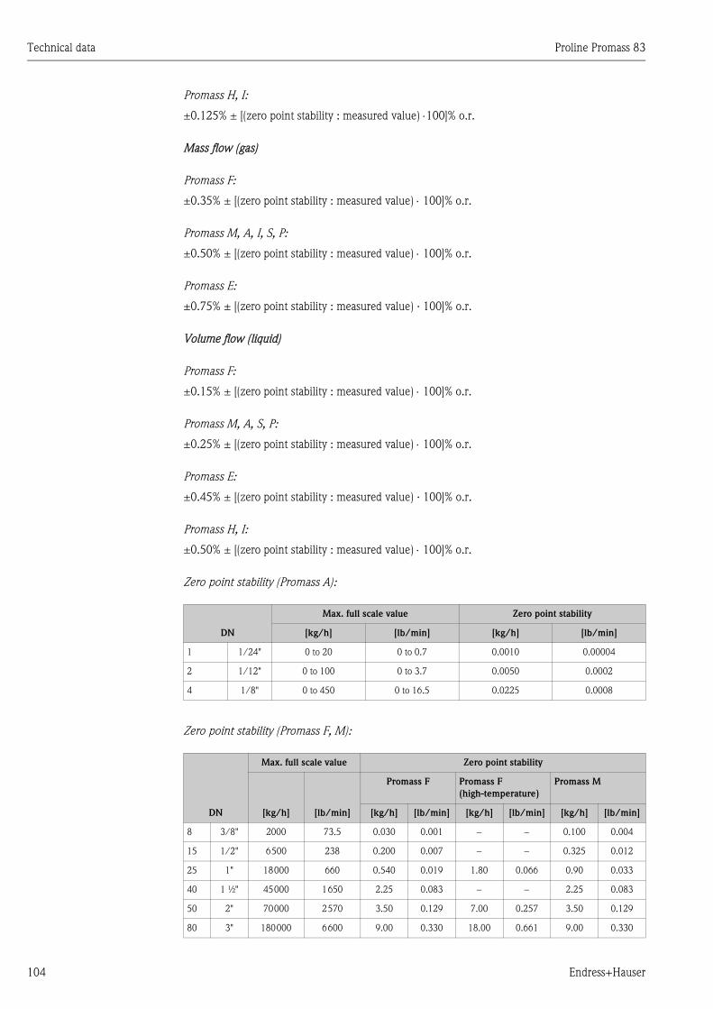
Technical data Proline Promass 83
104 Endress+Hauser
Promass H, I:
±0.125% ± [(zero point stability : measured value) ⋅100]% o.r.
Mass flow (gas)
Promass F:
±0.35% ± [(zero point stability : measured value) ⋅ 100]% o.r.
Promass M, A, I, S, P:
±0.50% ± [(zero point stability : measured value) ⋅ 100]% o.r.
Promass E:
±0.75% ± [(zero point stability : measured value) · 100]% o.r.
Volume flow (liquid)
Promass F:
±0.15% ± [(zero point stability : measured value) ⋅ 100]% o.r.
Promass M, A, S, P:
±0.25% ± [(zero point stability : measured value) ⋅ 100]% o.r.
Promass E:
±0.45% ± [(zero point stability : measured value) · 100]% o.r.
Promass H, I:
±0.50% ± [(zero point stability : measured value) ⋅ 100]% o.r.
Zero point stability (Promass A):
Zero point stability (Promass F, M):
DN
Max. full scale value Zero point stability
[kg/h] [lb/min] [kg/h] [lb/min]
1 1/24" 0 to 20 0 to 0.7 0.0010 0.00004
2 1/12" 0 to 100 0 to 3.7 0.0050 0.0002
4 1/8" 0 to 450 0 to 16.5 0.0225 0.0008
DN
Max. full scale value Zero point stability
[kg/h] [lb/min]
Promass F Promass F
(high-temperature)
Promass M
[kg/h] [lb/min] [kg/h] [lb/min] [kg/h] [lb/min]
8 3/8" 2000 73.5 0.030 0.001 − − 0.100 0.004
15 1/2" 6500 238 0.200 0.007 − − 0.325 0.012
25 1" 18000 660 0.540 0.019 1.80 0.066 0.90 0.033
40 1 ½" 45000 1650 2.25 0.083 − − 2.25 0.083
50 2" 70000 2570 3.50 0.129 7.00 0.257 3.50 0.129
80 3" 180000 6600 9.00 0.330 18.00 0.661 9.00 0.330
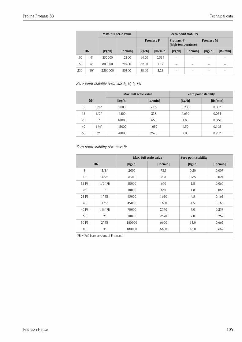
Proline Promass 83 Technical data
Endress+Hauser 105
Zero point stability (Promass E, H, S, P):
Zero point stability (Promass I):
100 4" 350000 12860 14.00 0.514 − − − −
150 6" 800000 29400 32.00 1.17 − − − −
250 10" 2200000 80860 88.00 3.23 − − − −
DN
Max. full scale value Zero point stability
[kg/h] [lb/min] [kg/h] [lb/min]
8 3/8" 2000 73.5 0.200 0.007
15 1/2" 6500 238 0.650 0.024
25 1" 18000 660 1.80 0.066
40 1 ½" 45000 1650 4.50 0.165
50 2" 70000 2570 7.00 0.257
DN
Max. full scale value Zero point stability
[kg/h] [lb/min] [kg/h] [lb/min]
8 3/8" 2000 73.5 0.20 0.007
15 1/2" 6500 238 0.65 0.024
15 FB 1/2" FB 18000 660 1.8 0.066
25 1" 18000 660 1.8 0.066
25 FB 1" FB 45000 1650 4.5 0.165
40 1 ½" 45000 1650 4.5 0.165
40 FB 1 ½" FB 70000 2570 7.0 0.257
50 2" 70000 2570 7.0 0.257
50 FB 2" FB 180000 6600 18.0 0.662
80 3" 180000 6600 18.0 0.662
FB = Full bore versions of Promass I
DN
Max. full scale value Zero point stability
[kg/h] [lb/min]
Promass F Promass F
(high-temperature)
Promass M
[kg/h] [lb/min] [kg/h] [lb/min] [kg/h] [lb/min]
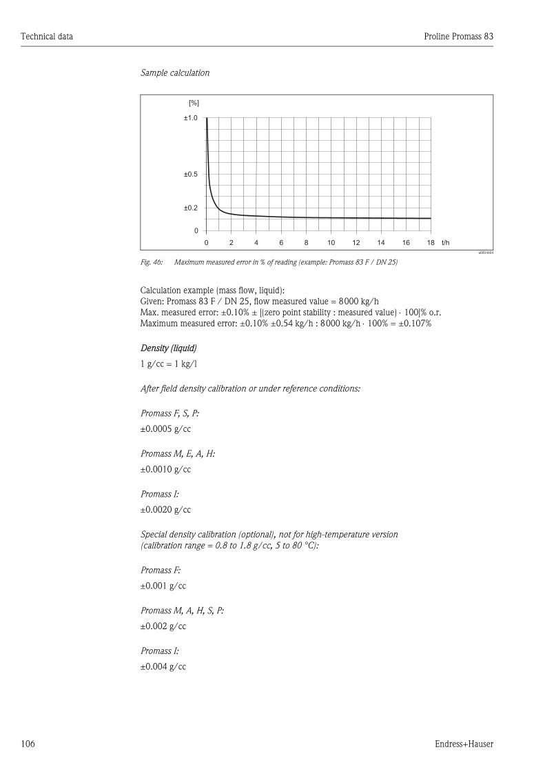
Technical data Proline Promass 83
106 Endress+Hauser
Sample calculation
a0004604
Fig. 46: Maximum measured error in % of reading (example: Promass 83 F / DN 25)
Calculation example (mass flow, liquid):
Given: Promass 83 F / DN 25, flow measured value = 8000 kg/h
Max. measured error: ±0.10% ± [(zero point stability : measured value) ⋅ 100]% o.r.
Maximum measured error: ±0.10% ±0.54 kg/h : 8000 kg/h ⋅ 100% = ±0.107%
Density (liquid)
1 g/cc = 1 kg/l
After field density calibration or under reference conditions:
Promass F, S, P:
±0.0005 g/cc
Promass M, E, A, H:
±0.0010 g/cc
Promass I:
±0.0020 g/cc
Special density calibration (optional), not for high-temperature version
(calibration range = 0.8 to 1.8 g/cc, 5 to 80 °C):
Promass F:
±0.001 g/cc
Promass M, A, H, S, P:
±0.002 g/cc
Promass I:
±0.004 g/cc
0
±0.5
±0.2
±1.0
[%]
0 2 4 6 8 10 12 14 16 18 t/h
Proline Promass 83 Technical data
Endress+Hauser 107
Standard calibration:
Promass F, S, P:
±0.01 g/cc
Promass M, E, A, H, I:
±0.02 g/cc
Temperature
±0.5 °C ±0.005 ⋅ T (T = fluid temperature in °C)
±1 °F ±0.003 ⋅ (T–32) (T = fluid temperature in °F)
Repeatability Mass flow (liquid):
Promass F, M, A, H, I, S, P:
±0.05% ± [1/2 ⋅ (zero point stability : measured value) ⋅ 100]% o.r.
Promass E:
±0.15% ± [1/2 ⋅ (zero point stability : measured value) ⋅100]% o.r.
Mass flow (gas):
Promass F, M, A, I, S, P:
±0.25% ± [1/2 ⋅ (zero point stability : measured value) ⋅ 100]% o.r.
Promass E:
±0.35% ± [1/2 ⋅ (zero point stability : measured value) ⋅100]% o.r.
Volume flow (liquid):
Promass F:
±0.05% ± [1/2 ⋅ (zero point stability : measured value) ⋅ 100]% o.r.
Promass M, A:
±0.10% ± [1/2 ⋅ (zero point stability : measured value) ⋅ 100]% o.r.
Promass E:
±0.25% ± [1/2 ⋅ (zero point stability : measured value) ⋅100]% o.r.
Promass H, I, S, P:
±0.20% ± [1/2 ⋅ (zero point stability : measured value) ⋅ 100]% o.r.
o.r. = of reading
Zero point stability: see "Max. measured error"→ Page 103 ff.
Calculation example (mass flow, liquid):
Given: Promass 83 F / DN 25, flow measured value = 8000 kg/h
Repeatability: ±0.05% ± [1/2 ⋅ (zero point stability : measured value) ⋅ 100]% o.r.
Repeatability: ±0.05% ±1/2 ⋅ 0.54 kg/h : 8000 kg/h ⋅ 100% = ±0.053%
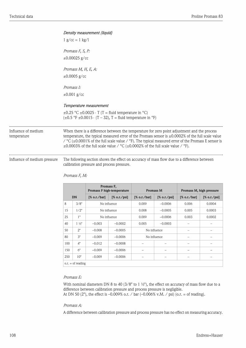
Technical data Proline Promass 83
108 Endress+Hauser
Density measurement (liquid)
1 g/cc = 1 kg/l
Promass F, S, P:
±0.00025 g/cc
Promass M, H, E, A:
±0.0005 g/cc
Promass I:
±0.001 g/cc
Temperature measurement
±0.25 °C ±0.0025 ⋅ T (T = fluid temperature in °C)
(±0.5 °F ±0.0015 ⋅ (T – 32), T = fluid temperature in °F)
Influence of medium
temperature
When there is a difference between the temperature for zero point adjustment and the process
temperature, the typical measured error of the Promass sensor is ±0.0002% of the full scale value
/ °C (±0.0001% of the full scale value / °F). The typical measured error of the Promass E sensor is
±0.0003% of the full scale value / °C (±0.0002% of the full scale value / °F).
Influence of medium pressure The following section shows the effect on accuracy of mass flow due to a difference between
calibration pressure and process pressure.
Promass F, M:
Promass E:
With nominal diameters DN 8 to 40 (3/8" to 1 ½"), the effect on accuracy of mass flow due to a
difference between calibration pressure and process pressure is negligible.
At DN 50 (2"), the effect is –0.009% o.r. / bar (–0.006% v.M. / psi) (o.r. = of reading).
Promass A:
A difference between calibration pressure and process pressure has no effect on measuring accuracy.
DN
Promass F,
Promass F high-temperature Promass M Promass M, high pressure
[% o.r./bar] [% o.r./psi] [% o.r./bar] [% o.r./psi] [% o.r./bar] [% o.r./psi]
8 3/8" No influence 0.009 −0.0006 0.006 0.0004
15 1/2" No influence 0.008 −0.0005 0.005 0.0003
25 1" No influence 0.009 −0.0006 0.003 0.0002
40 1 ½" −0.003 −0.0002 0.005 −0.0003 − −
50 2" −0.008 −0.0005 No influence − −
80 3" −0.009 −0.0006 No influence − −
100 4" −0.012 −0.0008 − − − −
150 6" −0.009 −0.0006 − − − −
250 10" −0.009 −0.0006 − − − −
o.r. = of reading
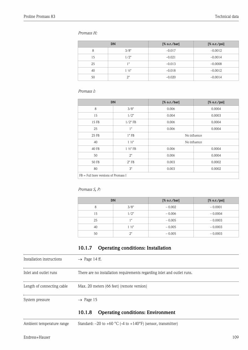
Proline Promass 83 Technical data
Endress+Hauser 109
Promass H:
Promass I:
Promass S, P:
10.1.7 Operating conditions: Installation
Installation instructions → Page 14 ff.
Inlet and outlet runs There are no installation requirements regarding inlet and outlet runs.
Length of connecting cable Max. 20 meters (66 feet) (remote version)
System pressure → Page 15
10.1.8 Operating conditions: Environment
Ambient temperature range Standard: –20 to +60 °C (-4 to +140°F) (sensor, transmitter)
DN [% o.r./bar] [% o.r./psi]
8 3/8" –0.017 –0.0012
15 1/2" –0.021 –0.0014
25 1" –0.013 –0.0008
40 1 ½" –0.018 –0.0012
50 2" –0.020 –0.0014
DN [% o.r./bar] [% o.r./psi]
8 3/8" 0.006 0.0004
15 1/2" 0.004 0.0003
15 FB 1/2" FB 0.006 0.0004
25 1" 0.006 0.0004
25 FB 1" FB No influence
40 1 ½" No influence
40 FB 1 ½" FB 0.006 0.0004
50 2" 0.006 0.0004
50 FB 2" FB 0.003 0.0002
80 3" 0.003 0.0002
FB = Full bore versions of Promass I
DN [% o.r./bar] [% o.r./psi]
8 3/8" – 0.002 – 0.0001
15 1/2" – 0.006 – 0.0004
25 1" – 0.005 – 0.0003
40 1 ½" – 0.005 – 0.0003
50 2" – 0.005 – 0.0003
Technical data Proline Promass 83
110 Endress+Hauser
Optional: –40 to +60 °C (-40 to +140°F) (sensor, transmitter)
! Note!
• Install the device at a shady location. Avoid direct sunlight, particularly in warm climatic regions.
• At ambient temperatures below –20 °C (–4 °F) the readability of the display may be impaired.
Storage temperature –40 to +80 °C (–40 to +175 °F) (preferably +20 °C (+68 °F))
Degree of protection Standard: IP 67 (NEMA 4X) for transmitter and sensor
Shock resistance According to IEC 68-2-31
Vibration resistance Acceleration up to 1 g, 10 to 150 Hz, following IEC 68-2-6
CIP cleaning Yes
SIP cleaning Yes
Electromagnetic compatibility
(EMC)
To EN 61326/A1 (IEC 1326) and NAMUR Recommendation NE 21
Proline Promass 83 Technical data
Endress+Hauser 111
10.1.9 Operating conditions: Process
Medium temperature range Sensor:
Promass F, A, H, P:
–50 to +200 °C (–58 to +392 °F)
Promass F (high-temperature version):
–50 to +350 °C (–58 to +662 °F)
Promass M, I, S:
–50 to +150 °C (–58 to +302 °F)
Promass E:
–40 to +125 °C (–40 to +257 °F)
Seals:
Promass F, E, H, I, S, P:
No internal seals
Promass M:
Viton –15 to +200 °C ( –5 to +392 °F)
EPDM –40 to +160 °C (–40 to +320 °F)
Silicon –60 to +200 °C (–76 to +392 °F)
Kalrez –20 to +275 °C (–4 to +527 °F);
FEP sheathed (not for gas applications): –60 to +200 °C (–76 to +392 °F)
Promass A
No seals inlying.
Only for mounting sets with threaded connections:
Viton –15 to +200 °C ( –5 to +392 °F)
EPDM –40 to +160 °C (–40 to +320 °F)
Silicon –60 to +200 °C (–76 to +392 °F)
Kalrez –20 to +275 °C (–4 to +527 °F);
Technical data Proline Promass 83
112 Endress+Hauser
Limiting medium pressure
range (rated pressure)
The material load diagrams (pressure-temperature diagrams) for the process connections are
provided in the separate "Technical Information" document on the device in question. This can be
downloaded as a PDF file from www.endress.com.
A list of the "Technical Information" documents available is provided in the "Documentation"
section → Page 128
Pressure ranges of secondary containment:
Promass F:
DN 8 to 50: 40 bar (580 psi)
DN 80: 25 bar (362 ps)
DN 100 to 150: 16 bar (232 psi)
DN 250: 10 bar (145 psi)
Promass M:
100 bar (1450) psi
Promass E:
No secondary containment
Promass A:
25 bar (362) psi
Promass H, P:
DN 8 to 15: 25 bar (362 psi)
DN 25 to 50: 16 bar (232 psi)
Promass I:
40 bar (580 psi)
Promass S:
DN 8 to 40: 16 bar (232 psi)
DN 50: 10 bar (145 psi)
Limiting flow See the "Measuring range" section→ Page 100→ Page 100
Select nominal diameter by optimizing between required flow range and permissible pressure loss.
See the "Measuring range" section for a list of max. possible full scale values.
• The minimum recommended full scale value is approx. 1/20 of the max. full scale value.
• In most applications, 20 to 50% of the maximum full scale value can be considered ideal.
• Select a lower full scale value for abrasive substances such as liquids with entrained solids (flow
velocity < 1 m/s (3 ft/s)).
• For gas measurement the following rules apply:
– Flow velocity in the measuring tubes should not be more than half the sonic velocity
(0.5 Mach).
– The maximum mass flow depends on the density of the gas: formula → Page 101
Proline Promass 83 Technical data
Endress+Hauser 113
Pressure loss (SI units) Pressure loss depends on the properties of the fluid and on its flow. The following formulas can be
used to approximately calculate the pressure loss:
Pressure loss formulas for Promass F, M, E
Pressure loss formulas for Promass H, I, S, P
Pressure loss formulas for Promass A
Reynolds number
a0004623
Re ≥ 23001)
a0004626
Re < 2300
a0004628
Δp = pressure loss [mbar]
ν = kinematic viscosity [m2/s]
m = mass flow [kg/s]
ρ = fluid density [kg/m3]
d = inside diameter of measuring tubes [m]
K to K2 = constants (depending on nominal diameter)
1) To compute the pressure loss for gases, always use the formula for Re ≥ 2300.
Reynolds number
a0003381
Re ≥ 23001)
a0004631
Re < 2300
a0004633
Δp = pressure loss [mbar]
ν = kinematic viscosity [m2/s]
m = mass flow [kg/s]
ρ = fluid density [kg/m3]
d = inside diameter of measuring tubes [m]
K to K3 = constants (depending on nominal diameter)
1) To compute the pressure loss for gases, always use the formula for Re ≥ 2300.
Reynolds number
a0003381
Re ≥ 23001)
a0003380
Re < 2300
a0003379
Δp = pressure loss [mbar]
ν = kinematic viscosity [m2/s]
m = mass flow [kg/s]
ρ = density [kg/m3]
d = inside diameter of measuring tubes [m]
K to K1 = constants (depending on nominal diameter)
1) To compute the pressure loss for gases, always use the formula for Re ≥ 2300.
Re =2 · m
� � �· d · ·
� �p = K · · m ·0.25 1.85 –0.86
�
�p = K1 · · m +�K2 · · m�
0.25 2
�
Re =� � �· d · ·
4 · m
� � �p = K · · m ·0.25 1.75 –0.75
· K3 · m2
�
�p = K1 · · m� ·K3 · m
2
�
Re =� � �· d · ·
4 · m
� �p = K ·0.25
· m ·1.75 –0.75
�
� �p = K1 · · m
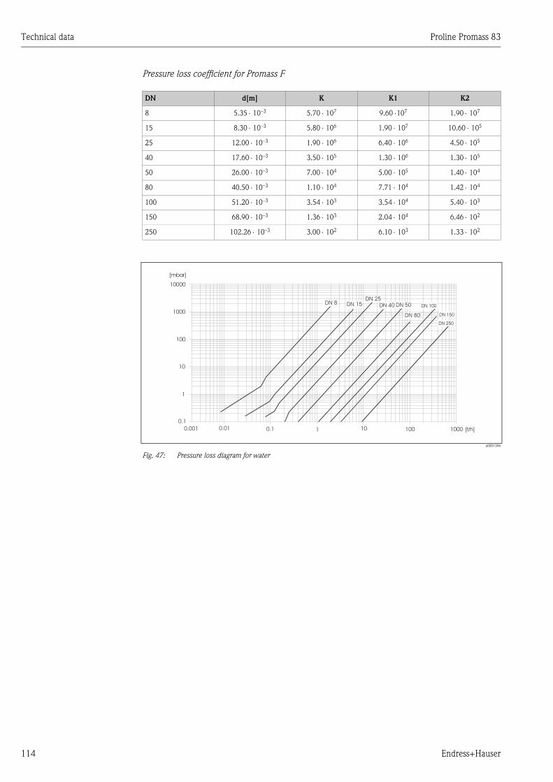
Technical data Proline Promass 83
114 Endress+Hauser
Pressure loss coefficient for Promass F
a0001396
Fig. 47: Pressure loss diagram for water
DN d[m] K K1 K2
8 5.35 ⋅ 10–3 5.70 ⋅ 107 9.60 ⋅107 1.90 ⋅ 107
15 8.30 ⋅ 10–3 5.80 ⋅ 106 1.90 ⋅ 107 10.60 ⋅ 105
25 12.00 ⋅ 10–3 1.90 ⋅ 106 6.40 ⋅ 106 4.50 ⋅ 105
40 17.60 ⋅ 10–3 3.50 ⋅ 105 1.30 ⋅ 106 1.30 ⋅ 105
50 26.00 ⋅ 10–3 7.00 ⋅ 104 5.00 ⋅ 105 1.40 ⋅ 104
80 40.50 ⋅ 10–3 1.10 ⋅ 104 7.71 ⋅ 104 1.42 ⋅ 104
100 51.20 ⋅ 10–3 3.54 ⋅ 103 3.54 ⋅ 104 5.40 ⋅ 103
150 68.90 ⋅ 10–3 1.36 ⋅ 103 2.04 ⋅ 104 6.46 ⋅ 102
250 102.26 ⋅ 10–3 3.00 ⋅ 102 6.10 ⋅ 103 1.33 ⋅ 102
DN 50DN 40DN 25
DN 8
10000
1000
100
10
1
0.1
0.001 0.01 0.1 1 10 100 1000
DN 15
DN 80
DN 100
[mbar]
[t/h]
DN 150
DN 250
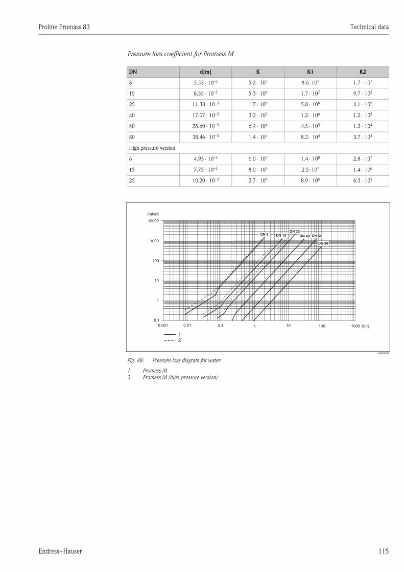
Proline Promass 83 Technical data
Endress+Hauser 115
Pressure loss coefficient for Promass M
a0004605
Fig. 48: Pressure loss diagram for water
1 Promass M
2 Promass M (high pressure version)
DN d[m] K K1 K2
8 5.53 ⋅ 10–3 5.2 ⋅ 107 8.6 ⋅107 1.7 ⋅ 107
15 8.55 ⋅ 10–3 5.3 ⋅ 106 1.7 ⋅ 107 9.7 ⋅ 105
25 11.38 ⋅ 10–3 1.7 ⋅ 106 5.8 ⋅ 106 4.1 ⋅ 105
40 17.07 ⋅ 10–3 3.2 ⋅ 105 1.2 ⋅ 106 1.2 ⋅ 105
50 25.60 ⋅ 10–3 6.4 ⋅ 104 4.5 ⋅ 105 1.3 ⋅ 104
80 38.46 ⋅ 10–3 1.4 ⋅ 104 8.2 ⋅ 104 3.7 ⋅ 104
High pressure version
8 4.93 ⋅ 10–3 6.0 ⋅ 107 1.4 ⋅ 108 2.8 ⋅ 107
15 7.75 ⋅ 10–3 8.0 ⋅ 106 2.5 ⋅107 1.4 ⋅ 106
25 10.20 ⋅ 10–3 2.7 ⋅ 106 8.9 ⋅ 106 6.3 ⋅ 105
DN 50DN 40
DN 25DN 8
10000
1000
100
10
1
0.1
0.001 0.01 0.1 1 10 100 1000
DN 15
DN 80
[mbar]
[t/h]
12
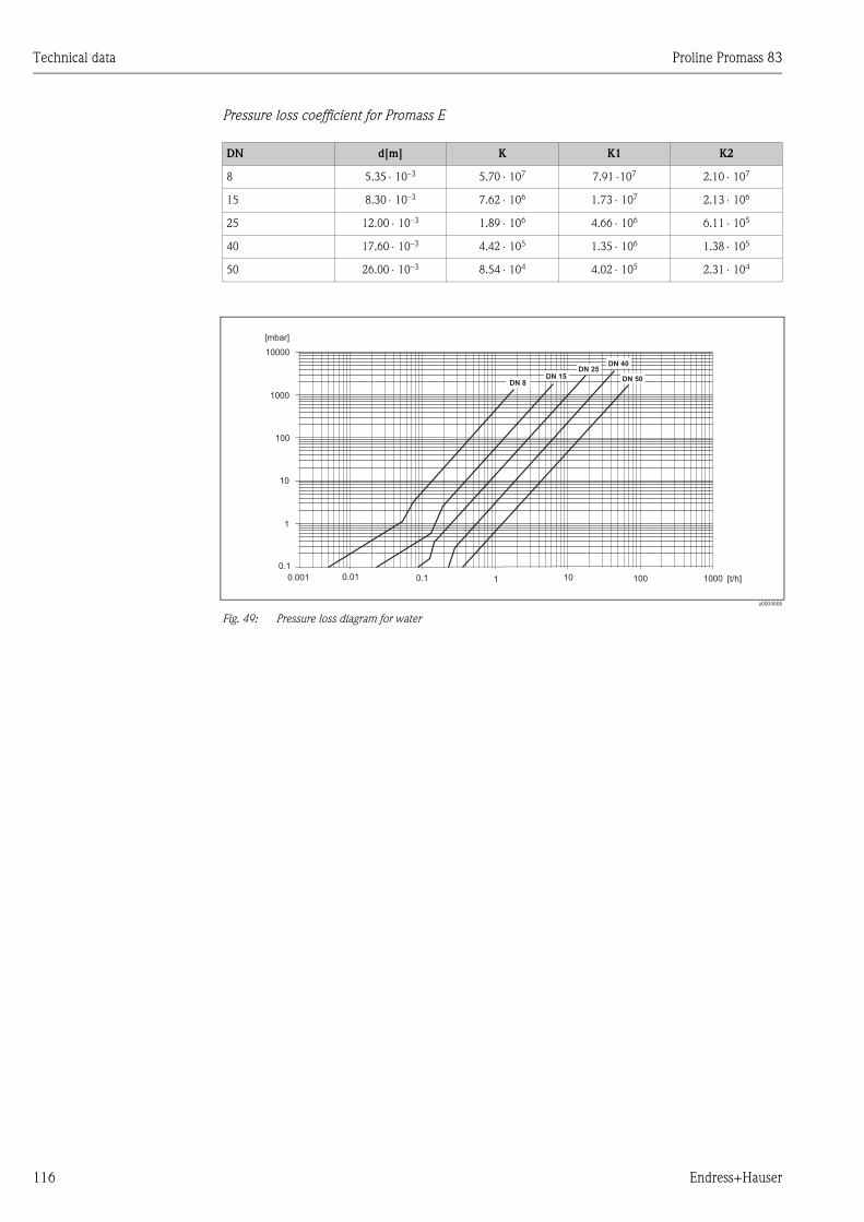
Technical data Proline Promass 83
116 Endress+Hauser
Pressure loss coefficient for Promass E
a0004606
Fig. 49: Pressure loss diagram for water
DN d[m] K K1 K2
8 5.35 ⋅ 10–3 5.70 ⋅ 107 7.91 ⋅107 2.10 ⋅ 107
15 8.30 ⋅ 10–3 7.62 ⋅ 106 1.73 ⋅ 107 2.13 ⋅ 106
25 12.00 ⋅ 10–3 1.89 ⋅ 106 4.66 ⋅ 106 6.11 ⋅ 105
40 17.60 ⋅ 10–3 4.42 ⋅ 105 1.35 ⋅ 106 1.38 ⋅ 105
50 26.00 ⋅ 10–3 8.54 ⋅ 104 4.02 ⋅ 105 2.31 ⋅ 104
DN 50
DN 40DN 25
DN 8
10000
1000
100
10
1
0.1
0.001 0.01 0.1 1 10 100 1000
DN 15
[mbar]
[t/h]
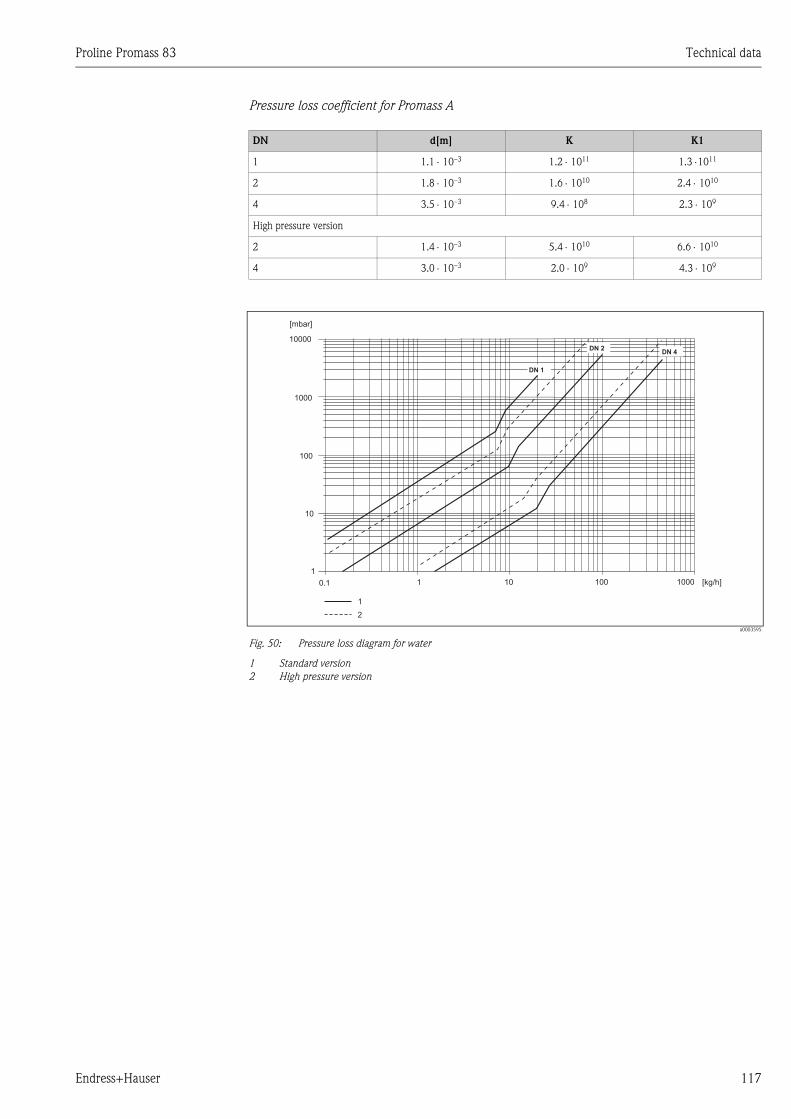
Proline Promass 83 Technical data
Endress+Hauser 117
Pressure loss coefficient for Promass A
a0003595
Fig. 50: Pressure loss diagram for water
1 Standard version
2 High pressure version
DN d[m] K K1
1 1.1 ⋅ 10–3 1.2 ⋅ 1011 1.3 ⋅1011
2 1.8 ⋅ 10–3 1.6 ⋅ 1010 2.4 ⋅ 1010
4 3.5 ⋅ 10–3 9.4 ⋅ 108 2.3 ⋅ 109
High pressure version
2 1.4 ⋅ 10–3 5.4 ⋅ 1010 6.6 ⋅ 1010
4 3.0 ⋅ 10–3 2.0 ⋅ 109 4.3 ⋅ 109
[mbar]
[kg/h]
1
DN 2
10000
1000
100
10
1
0.1 1 10 100 1000
DN 4
DN 1
2
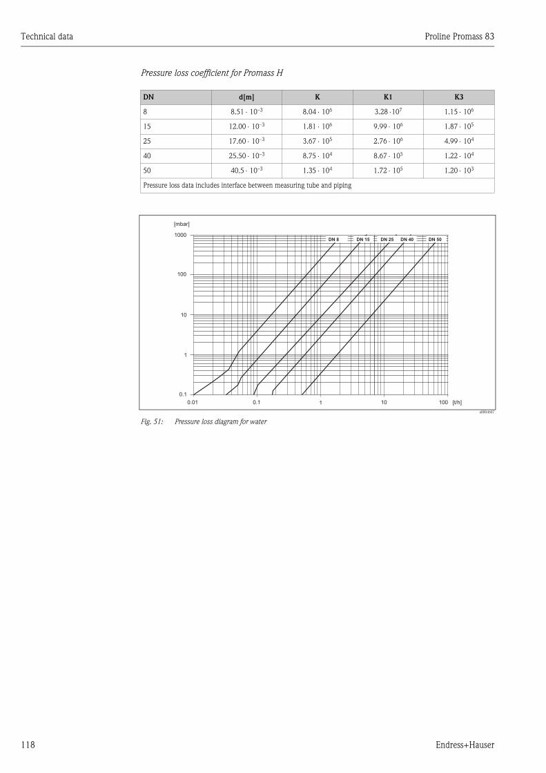
Technical data Proline Promass 83
118 Endress+Hauser
Pressure loss coefficient for Promass H
a0004607
Fig. 51: Pressure loss diagram for water
DN d[m] K K1 K3
8 8.51 ⋅ 10–3 8.04 ⋅ 106 3.28 ⋅107 1.15 ⋅ 106
15 12.00 ⋅ 10–3 1.81 ⋅ 106 9.99 ⋅ 106 1.87 ⋅ 105
25 17.60 ⋅ 10–3 3.67 ⋅ 105 2.76 ⋅ 106 4.99 ⋅ 104
40 25.50 ⋅ 10–3 8.75 ⋅ 104 8.67 ⋅ 105 1.22 ⋅ 104
50 40.5 ⋅ 10–3 1.35 ⋅ 104 1.72 ⋅ 105 1.20 ⋅ 103
Pressure loss data includes interface between measuring tube and piping
1000
100
10
1
0.1
0.01 0.1 1 10 100
[mbar]
[t/h]
DN 40 DN 50DN 25DN 15DN 8
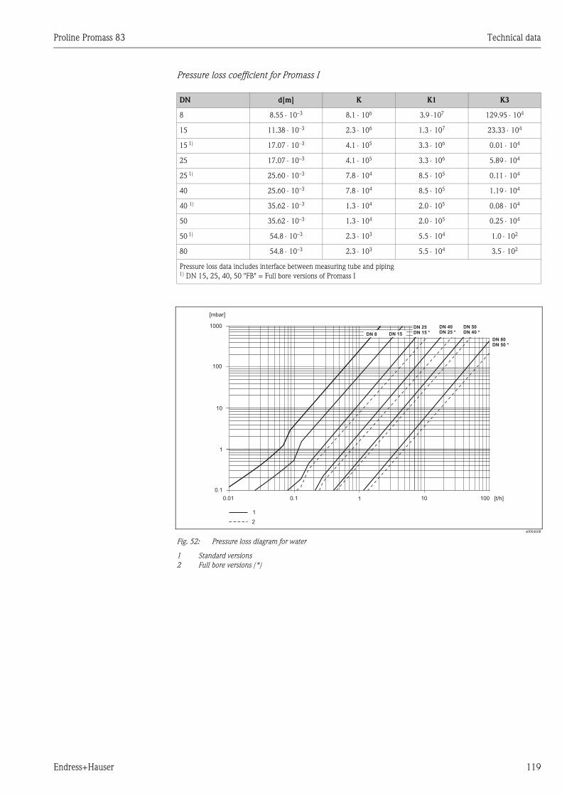
Proline Promass 83 Technical data
Endress+Hauser 119
Pressure loss coefficient for Promass I
a0004608
Fig. 52: Pressure loss diagram for water
1 Standard versions
2 Full bore versions (*)
DN d[m] K K1 K3
8 8.55 ⋅ 10–3 8.1 ⋅ 106 3.9 ⋅107 129.95 ⋅ 104
15 11.38 ⋅ 10–3 2.3 ⋅ 106 1.3 ⋅ 107 23.33 ⋅ 104
15 1) 17.07 ⋅ 10–3 4.1 ⋅ 105 3.3 ⋅ 106 0.01 ⋅ 104
25 17.07 ⋅ 10–3 4.1 ⋅ 105 3.3 ⋅ 106 5.89 ⋅ 104
25 1) 25.60 ⋅ 10–3 7.8 ⋅ 104 8.5 ⋅ 105 0.11 ⋅ 104
40 25.60 ⋅ 10–3 7.8 ⋅ 104 8.5 ⋅ 105 1.19 ⋅ 104
40 1) 35.62 ⋅ 10–3 1.3 ⋅ 104 2.0 ⋅ 105 0.08 ⋅ 104
50 35.62 ⋅ 10–3 1.3 ⋅ 104 2.0 ⋅ 105 0.25 ⋅ 104
50 1) 54.8 ⋅ 10–3 2.3 ⋅ 103 5.5 ⋅ 104 1.0 ⋅ 102
80 54.8 ⋅ 10–3 2.3 ⋅ 103 5.5 ⋅ 104 3.5 ⋅ 102
Pressure loss data includes interface between measuring tube and piping1) DN 15, 25, 40, 50 "FB" = Full bore versions of Promass I
1000
100
10
1
0.1
0.01 0.1 1 10 100
DN 40
DN 25 *
DN 50
DN 40 *
DN 25
DN 15 *DN 15
[mbar]
[t/h]
1
DN 8
DN 80
DN 50 *
2
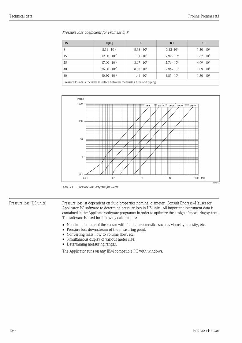
Technical data Proline Promass 83
120 Endress+Hauser
Pressure loss coefficient for Promass S, P
a0004607
Abb. 53: Pressure loss diagram for water
Pressure loss (US units) Pressure loss ist dependent on fluid properties nominal diameter. Consult Endress+Hauser for
Applicator PC software to determine pressure loss in US units. All important instrument data is
contained in the Applicator software programm in order to optimize the design of measuring system.
The software is used for following calculations:
• Nominal diameter of the sensor with fluid characteristics such as viscosity, density, etc.
• Pressure loss downstream ot the measuring point.
• Converting mass flow to volume flow, etc.
• Simultaneous display of various meter size.
• Determining measuring ranges.
The Applicator runs on any IBM compatible PC with windows.
DN d[m] K K1 K3
8 8.31 ⋅ 10–3 8.78 ⋅ 106 3.53 ⋅107 1.30 ⋅ 106
15 12.00 ⋅ 10–3 1.81 ⋅ 106 9.99 ⋅ 106 1.87 ⋅ 105
25 17.60 ⋅ 10–3 3.67 ⋅ 105 2.76 ⋅ 106 4.99 ⋅ 104
40 26.00 ⋅ 10–3 8.00 ⋅ 104 7.96 ⋅ 105 1.09 ⋅ 104
50 40.50 ⋅ 10–3 1.41 ⋅ 104 1.85 ⋅ 105 1.20 ⋅ 103
Pressure loss data includes interface between measuring tube and piping
1000
100
10
1
0.1
0.01 0.1 1 10 100
[mbar]
[t/h]
DN 40 DN 50DN 25DN 15DN 8
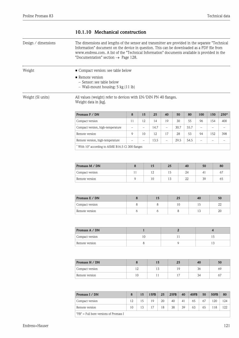
Proline Promass 83 Technical data
Endress+Hauser 121
10.1.10 Mechanical construction
Design / dimensions The dimensions and lengths of the sensor and transmitter are provided in the separate "Technical
Information" document on the device in question. This can be downloaded as a PDF file from
www.endress.com. A list of the "Technical Information" documents available is provided in the
"Documentation" section → Page 128.
Weight • Compact version: see table below
• Remote version
– Sensor: see table below
– Wall-mount housing: 5 kg (11 lb)
Weight (SI units) All values (weight) refer to devices with EN/DIN PN 40 flanges.
Weight data in [kg].
Promass F / DN 8 15 25 40 50 80 100 150 250*
Compact version 11 12 14 19 30 55 96 154 400
Compact version, high-temperature − − 14.7 − 30.7 55.7 − − −
Remote version 9 10 12 17 28 53 94 152 398
Remote version, high-temperature − − 13.5 − 29.5 54.5 − − −
* With 10" according to ASME B16.5 Cl 300 flanges
Promass M / DN 8 15 25 40 50 80
Compact version 11 12 15 24 41 67
Remote version 9 10 13 22 39 65
Promass E / DN 8 15 25 40 50
Compact version 8 8 10 15 22
Remote version 6 6 8 13 20
Promass A / DN 1 2 4
Compact version 10 11 15
Remote version 8 9 13
Promass H / DN 8 15 25 40 50
Compact version 12 13 19 36 69
Remote version 10 11 17 34 67
Promass I / DN 8 15 15FB 25 25FB 40 40FB 50 50FB 80
Compact version 12 15 19 20 40 41 65 67 120 124
Remote version 10 13 17 18 38 39 63 65 118 122
"FB" = Full bore versions of Promass I
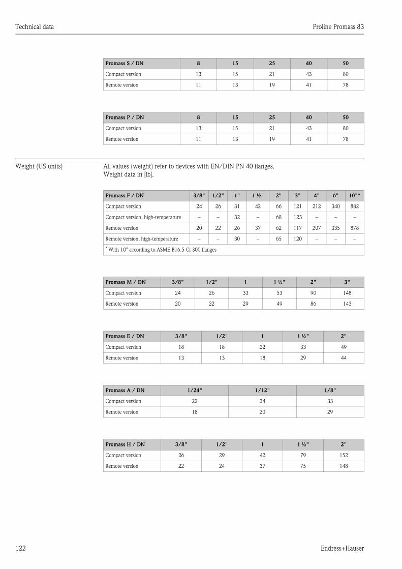
Technical data Proline Promass 83
122 Endress+Hauser
Weight (US units) All values (weight) refer to devices with EN/DIN PN 40 flanges.
Weight data in [lb].
Promass S / DN 8 15 25 40 50
Compact version 13 15 21 43 80
Remote version 11 13 19 41 78
Promass P / DN 8 15 25 40 50
Compact version 13 15 21 43 80
Remote version 11 13 19 41 78
Promass F / DN 3/8" 1/2" 1" 1 ½" 2" 3" 4" 6" 10"*
Compact version 24 26 31 42 66 121 212 340 882
Compact version, high-temperature – – 32 – 68 123 – – –
Remote version 20 22 26 37 62 117 207 335 878
Remote version, high-temperature – – 30 – 65 120 – – –
* With 10" according to ASME B16.5 Cl 300 flanges
Promass M / DN 3/8" 1/2" 1 1 ½" 2" 3"
Compact version 24 26 33 53 90 148
Remote version 20 22 29 49 86 143
Promass E / DN 3/8" 1/2" 1 1 ½" 2"
Compact version 18 18 22 33 49
Remote version 13 13 18 29 44
Promass A / DN 1/24" 1/12" 1/8"
Compact version 22 24 33
Remote version 18 20 29
Promass H / DN 3/8" 1/2" 1 1 ½" 2"
Compact version 26 29 42 79 152
Remote version 22 24 37 75 148
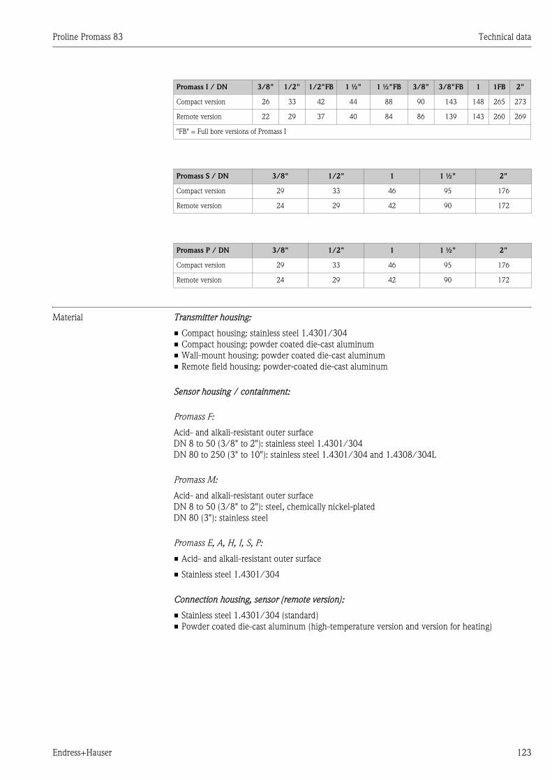
Proline Promass 83 Technical data
Endress+Hauser 123
Material Transmitter housing:
• Compact housing: stainless steel 1.4301/304
• Compact housing: powder coated die-cast aluminum
• Wall-mount housing: powder coated die-cast aluminum
• Remote field housing: powder-coated die-cast aluminum
Sensor housing / containment:
Promass F:
Acid- and alkali-resistant outer surface
DN 8 to 50 (3/8" to 2"): stainless steel 1.4301/304
DN 80 to 250 (3" to 10"): stainless steel 1.4301/304 and 1.4308/304L
Promass M:
Acid- and alkali-resistant outer surface
DN 8 to 50 (3/8" to 2"): steel, chemically nickel-plated
DN 80 (3"): stainless steel
Promass E, A, H, I, S, P:
• Acid- and alkali-resistant outer surface
• Stainless steel 1.4301/304
Connection housing, sensor (remote version):
• Stainless steel 1.4301/304 (standard)
• Powder coated die-cast aluminum (high-temperature version and version for heating)
Promass I / DN 3/8" 1/2" 1/2"FB 1 ½" 1 ½"FB 3/8" 3/8"FB 1 1FB 2"
Compact version 26 33 42 44 88 90 143 148 265 273
Remote version 22 29 37 40 84 86 139 143 260 269
"FB" = Full bore versions of Promass I
Promass S / DN 3/8" 1/2" 1 1 ½" 2"
Compact version 29 33 46 95 176
Remote version 24 29 42 90 172
Promass P / DN 3/8" 1/2" 1 1 ½" 2"
Compact version 29 33 46 95 176
Remote version 24 29 42 90 172
Technical data Proline Promass 83
124 Endress+Hauser
Process connections
Promass F:
• Flanges EN 1092-1 (DIN 2501) / according to ASME B16.5 / JIS B2238
→ stainless steel 1.4404/316L
• Flanges EN 1092-1 (DIN 2501) / according to ASME B16.5 / JIS B2238
→ Alloy C-22 2.4602/N 06022
• Flange DIN 11864-2 Form A (flat flange) → stainless steel 1.4404/316L
• Hygienic coupling DIN 11851 / SMS 1145 → stainless steel 1.4404/316L
• Couplings ISO 2853 / DIN 11864-1 → stainless steel 1.4404/316L
• Tri-Clamp (OD-tubes)→ stainless steel 1.4404/316L
• VCO connection → Stainless steel 1.4404/316L
Promass F (high-temperature version):
• Flanges EN 1092-1 (DIN 2501) / according to ASME B16.5 / JIS B2238
→ stainless steel 1.4404/316L
• Flanges EN 1092-1 (DIN 2501) / according to ASME B16.5 / JIS B2238
→ Alloy C-22 2.4602 (N 06022)
Promass M:
• Flanges EN 1092-1 (DIN 2501) / according to ASME B16.5 / JIS B2238
→ stainless steel 1.4404/316L, titanium grade 2
• Flange DIN 11864-2 Form A (flat flange) → stainless steel 1.4404/316L
• PVDF connection to DIN / ANSI / JIS
• Hygienic coupling DIN 11851 / SMS 1145 → stainless steel 1.4404/316L
• Couplings ISO 2853 / DIN 11864-1 → stainless steel 1.4404/316L
• Tri-Clamp (OD-tubes) → stainless steel 1.4404/316L
Promass M (high pressure version):
• Connector → stainless steel 1.4404/316L
• Couplings → stainless steel 1.4401/316
Promass E:
• Flanges EN 1092-1 (DIN 2501) / according to ASME B16.5 / JIS B2238
→ stainless steel 1.4404/316L
• Flange DIN 11864-2 Form A (flat flange) → stainless steel 1.4404/316L
• VCO connection → Stainless steel 1.4404/316L
• Hygienic coupling DIN 11851 / SMS 1145 → stainless steel 1.4404/316L
• Couplings ISO 2853 / DIN 11864-1 → stainless steel 1.4404/316L
• Tri-Clamp (OD-tubes) → stainless steel 1.4404/316L
Promass A:
• Mounting set for flanges EN 1092-1 (DIN 2501) / according to ASME B16.5 / JIS B2238
→ stainless steel 1.4539/904L, Alloy C-22 2.4602/N 06022.
Loose flanges → stainless steel 1.4404/316L
• VCO coupling → stainless steel 1.4539/904L, Alloy C-22 2.4602/N 06022
• Tri-Clamp (OD-tubes) (1/2") → stainless steel 1.4539/904L
• Mounting set for SWAGELOK (1/4", 1/8") → stainless steel 1.4401/316
• Mounting set for NPT-F (1/4") → stainless steel 1.4539/904L1.4539/904L,
Alloy C-22 2.4602/N 06022
Promass H:
• Flanges EN 1092-1 (DIN 2501) / according to ASME B16.5 / JIS B2238
→ stainless steel 1.4301/304, parts in contact with medium: zirconium 702
Proline Promass 83 Technical data
Endress+Hauser 125
Promass I:
• Flanges EN 1092-1 (DIN 2501) / according to ASME B16.5 / JIS B2238
→ stainless steel 1.4301/304
• Flange DIN 11864-2 Form A (flat flange) → titanium grade 2
• Hygienic coupling DIN 11851 / SMS 1145 → titanium grade 2
• Couplings ISO 2853 / DIN 11864-1 → titanium grade 2
• Tri-Clamp (OD-tubes) → titanium grade 2
Promass S:
• Flanges EN 1092-1 (DIN 2501) / JIS B2238 → stainless steel 1.4404/316/316L
• Flanges according to ASME B16.5 → stainless steel 1.4404/316/316L
• Flanges DIN 11864-2 Form A (flat flange) → stainless steel 1.4435/316L
• Sanitary connection DIN 11864-1, Form A/ DIN 11851/ SMS 1145
→ stainless steel 1.4435/316L
• Couplings ISO 2853 / DIN 11864-1 → stainless steel 1.4435/316L
• Tri-Clamp (OD-Tubes)→ stainless steel 1.4435/316L
• Clamp aseptic connection DIN 11864-3, Form A→ stainless steel 1.4435/316L
• Clamp pipe connection DIN 32676/ISO 2852→ stainless steel 1.4435/316L
Promass P:
• Flanges EN 1092-1 (DIN 2501) / JIS B2238 → stainless steel 1.4404/316/316L
• Flanges according to ASME B16.5 → stainless steel 1.4404/316/316L
• Flanges DIN 11864-2 Form A (Bundflansch), BioConnect® → stainless steel 1.4435/316L
• Sanitary connection DIN 11864-1, Form A → stainless steel 1.4435/316L
• Couplings ISO 2853 / DIN 11864-1 → stainless steel 1.4435/316L
• Tri-Clamp (OD-Tubes)→ stainless steel 1.4435/316L
• Clamp aseptic connection DIN 11864-3, Form A→ stainless steel 1.4435/316L
• Clamp pipe connection DIN 32676/ISO 2852, BioConnect®
→ stainless steel 1.4435/316L
Measuring tube(s):
Promass F:
• DN 8 to 100 (3/8" to 4"): stainless steel 1.4539/904L
• DN 150 (6"): stainless steel 1.4404/316L
• DN 250 (10"): stainless steel 1.4404/316L; manifold: CF3M
• DN 8 to 150 (3/8" to 6"): Alloy C-22 2.4602/N 06022
Promass F (high-temperature version):
• DN 25, 50, 80 (1", 2", 3"): Alloy C-22 2.4602/N 06022
Promass M:
• DN 8 to 50 (3/8" to 2"): titanium grade 9
• DN 80 (3"): titanium grade 2
Promass M (high pressure version):
• Titanium grade 9
Promass E, S:
• Stainless steel 1.4539/904L
Promass A:
• Stainless steel 1.4539/904L, Alloy C-22 2.4602/N 06022
Technical data Proline Promass 83
126 Endress+Hauser
Promass H:
• Zirconium 702/R 60702
Promass I:
• Titanium grade 9
• Titanium grade 2 (flange disks)
Promass P:
Stainless steel 1.4435/316L
Seals:
Promass F, E, H, I, S, P:
Welded process connections without internal seals
Promass M:
Viton, EPDM, silicon, Kalrez, FEP sheathing (not for gas applications)
Promass A:
Welded process connections without internal seals.
Only for mounting sets with threaded connections: Viton, EPDM, Silikon, Kalrez
Material load diagram The material load diagrams (pressure-temperature diagrams) for the process connections are
provided in the separate "Technical Information" document on the device in question. This can be
downloaded as a PDF file from www.endress.com.
A list of the "Technical Information" documents available is provided in the "Documentation"
section → Page 128
Process connections → Page 124 ff.
10.1.11 Human interface
Display elements • Liquid crystal display: illuminated, four lines with 16 characters per line
• Selectable display of different measured values and status variables
• 3 totalizers
• At ambient temperatures below –20 °C (–4 °F) the readability of the display may be impaired.
Operating elements • Local operation with three optical sensors (S/O/F)
• Application-specific Quick Setup menus for straightforward commissioning
Language groups Language groups available for operation in different countries:
• Western Europe and America (WEA):
English, German, Spanish, Italian, French, Dutch and Portuguese
• Eastern Europe and Scandinavia (EES):
English, Russian, Polish, Norwegian, Finnish, Swedish and Czech
• South and east Asia (SEA):
English, Japanese, Indonesian
• China (CIN):
English, Chinese
! Note!
You can change the language group via the operating program "ToF Tool - Fieldtool Package".
Proline Promass 83 Technical data
Endress+Hauser 127
Remote operation Operation by means of HART protocol
10.1.12 Certificates and approvals
CE mark The measuring system is in conformity with the statutory requirements of the EC Directives.
Endress+Hauser confirms successful testing of the device by affixing to it the CE mark.
C-tick mark The measuring system is in conformity with the EMC requirements of the "Australian
Communications and Media Authority (ACMA)".
Ex approval Information about currently available Ex versions (ATEX, FM, CSA) can be supplied by your E+H
Sales Center on request. All explosion protection data are given in a separate documentation which
is also available upon request.
Sanitary compatibility • 3A authorization (all measuring systems, except Promass H)
• EHEDG-tested (Promass A, I, S und P only)
Pressure device approval Flowmeters with a nominal diameter smaller or equal DN 25 are covered by Art. 3(3) of the
European directive 97/23/EC (Pressure Equipment Directive) and are designed according to sound
engineer practice. For larger nominal diameters, optional approvals according to Cat. II/III are
available where required (depends on fluid and process pressure).
Functional safety SIL -2:
In accordance with IEC 61508/IEC 61511-1 (FDIS)
Other standards and
guidelines
• EN 60529
Degrees of protection by housing (IP code)
• EN 61010-1
Protection Measures for Electrical Equipment for Measurement, Control, Regulation and
Laboratory Procedures
• EN 61326/A1 (IEC 1326)
"Emission in accordance with requirements for Class A".
Electromagnetic compatibility (EMC-requirements)
• NAMUR NE 21
Electromagnetic compatibility (EMC) of industrial process and laboratory control equipment
• NAMUR NE 43
Standardization of the signal level for the breakdown information of digital transmitters with
analog output signal.
• NAMUR NE 53
Software of field devices and signal-processing devices with digital electronics

Technical data Proline Promass 83
128 Endress+Hauser
10.1.13 Ordering information
The Endress +Hauser service organization can provide detailed ordering information and
information on the order codes on request.
10.1.14 Accessories
Various accessories, which can be ordered separately from Endress+Hauser, are available for the
transmitter and the sensor. → Page 80
10.1.15 Documentation
• Flow measuring technology (FA005D/06/en)
• Technical Information Promass 80F, 80M, 83F, 83M (TI053D/06/en)
• Technical Information Promass 80E, 83E (TI061D/06/en)
• Technical Information Promass 80A, 83A (TI 054D/06/en)
• Technical Information Promass 80H, 83H (TI074D/06/en)
• Technical Information Promass 80I, 83I (TI075D/06/en)
• Technical Information Promass 80S, 83S (TI076D/06/en)
• Technical Information Promass 80P, 83P (TI078D/06/en)
• Description of Device Functions Promass 83 (BA 060D/06/en)
• Supplementary documentation on Ex-ratings: ATEX, FM, CSA
• Functional Safety Manual Promass 80, 83 (SD077D/06/en)
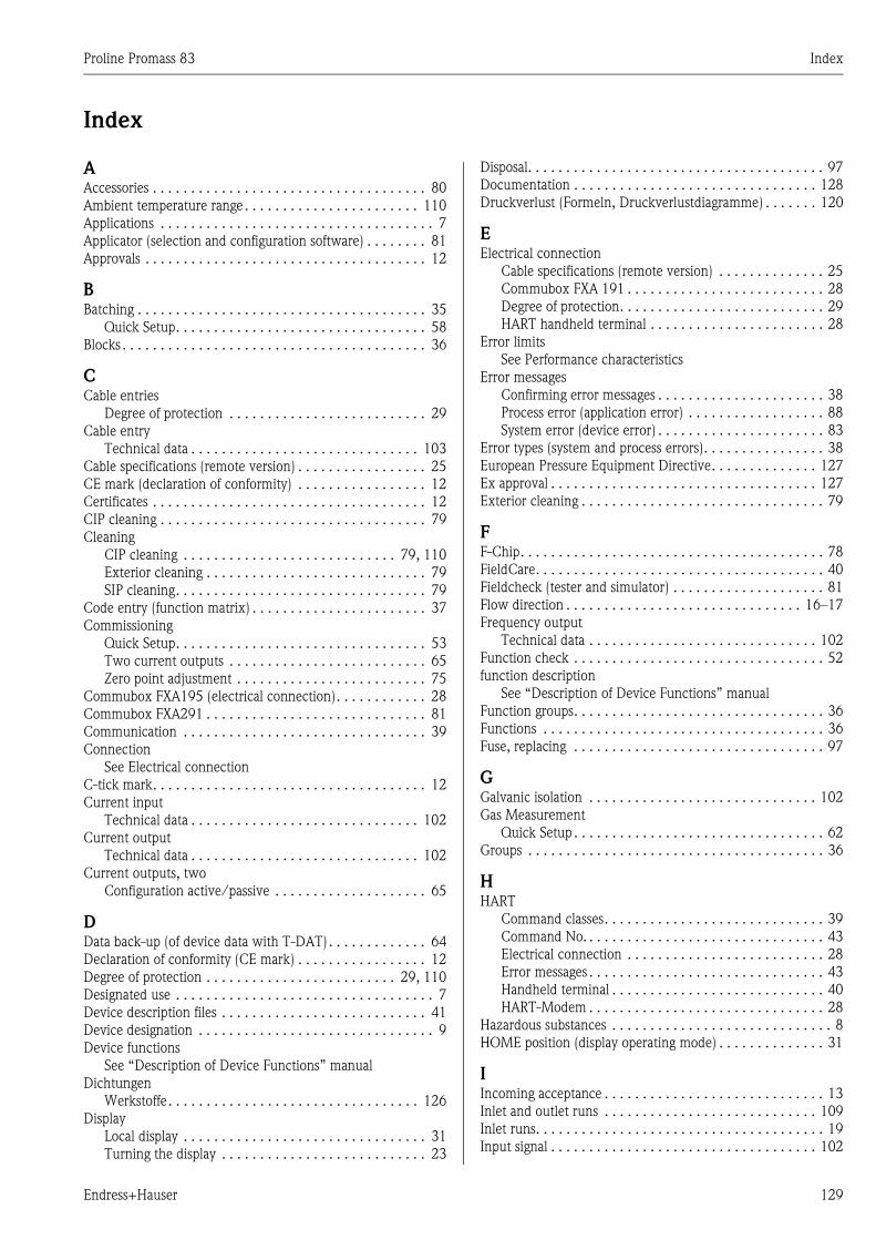
Proline Promass 83 Index
Endress+Hauser 129
Index
AAccessories . . . . . . . . . . . . . . . . . . . . . . . . . . . . . . . . . . . . 80
Ambient temperature range . . . . . . . . . . . . . . . . . . . . . . . 110
Applications . . . . . . . . . . . . . . . . . . . . . . . . . . . . . . . . . . . . 7
Applicator (selection and configuration software) . . . . . . . . 81
Approvals . . . . . . . . . . . . . . . . . . . . . . . . . . . . . . . . . . . . . 12
BBatching . . . . . . . . . . . . . . . . . . . . . . . . . . . . . . . . . . . . . . 35
Quick Setup. . . . . . . . . . . . . . . . . . . . . . . . . . . . . . . . . 58
Blocks . . . . . . . . . . . . . . . . . . . . . . . . . . . . . . . . . . . . . . . . 36
CCable entries
Degree of protection . . . . . . . . . . . . . . . . . . . . . . . . . . 29
Cable entry
Technical data . . . . . . . . . . . . . . . . . . . . . . . . . . . . . . 103
Cable specifications (remote version) . . . . . . . . . . . . . . . . . 25
CE mark (declaration of conformity) . . . . . . . . . . . . . . . . . 12
Certificates . . . . . . . . . . . . . . . . . . . . . . . . . . . . . . . . . . . . 12
CIP cleaning . . . . . . . . . . . . . . . . . . . . . . . . . . . . . . . . . . . 79
Cleaning
CIP cleaning . . . . . . . . . . . . . . . . . . . . . . . . . . . . 79, 110
Exterior cleaning . . . . . . . . . . . . . . . . . . . . . . . . . . . . . 79
SIP cleaning. . . . . . . . . . . . . . . . . . . . . . . . . . . . . . . . . 79
Code entry (function matrix) . . . . . . . . . . . . . . . . . . . . . . . 37
Commissioning
Quick Setup. . . . . . . . . . . . . . . . . . . . . . . . . . . . . . . . . 53
Two current outputs . . . . . . . . . . . . . . . . . . . . . . . . . . 65
Zero point adjustment . . . . . . . . . . . . . . . . . . . . . . . . . 75
Commubox FXA195 (electrical connection). . . . . . . . . . . . 28
Commubox FXA291 . . . . . . . . . . . . . . . . . . . . . . . . . . . . . 81
Communication . . . . . . . . . . . . . . . . . . . . . . . . . . . . . . . . 39
Connection
See Electrical connection
C-tick mark. . . . . . . . . . . . . . . . . . . . . . . . . . . . . . . . . . . . 12
Current input
Technical data . . . . . . . . . . . . . . . . . . . . . . . . . . . . . . 102
Current output
Technical data . . . . . . . . . . . . . . . . . . . . . . . . . . . . . . 102
Current outputs, two
Configuration active/passive . . . . . . . . . . . . . . . . . . . . 65
DData back-up (of device data with T-DAT) . . . . . . . . . . . . . 64
Declaration of conformity (CE mark) . . . . . . . . . . . . . . . . . 12
Degree of protection . . . . . . . . . . . . . . . . . . . . . . . . . 29, 110
Designated use . . . . . . . . . . . . . . . . . . . . . . . . . . . . . . . . . . 7
Device description files . . . . . . . . . . . . . . . . . . . . . . . . . . . 41
Device designation . . . . . . . . . . . . . . . . . . . . . . . . . . . . . . . 9
Device functions
See “Description of Device Functions” manual
Dichtungen
Werkstoffe . . . . . . . . . . . . . . . . . . . . . . . . . . . . . . . . . 126
Display
Local display . . . . . . . . . . . . . . . . . . . . . . . . . . . . . . . . 31
Turning the display . . . . . . . . . . . . . . . . . . . . . . . . . . . 23
Disposal. . . . . . . . . . . . . . . . . . . . . . . . . . . . . . . . . . . . . . . 97
Documentation . . . . . . . . . . . . . . . . . . . . . . . . . . . . . . . . 128
Druckverlust (Formeln, Druckverlustdiagramme) . . . . . . . 120
EElectrical connection
Cable specifications (remote version) . . . . . . . . . . . . . . 25
Commubox FXA 191 . . . . . . . . . . . . . . . . . . . . . . . . . . 28
Degree of protection. . . . . . . . . . . . . . . . . . . . . . . . . . . 29
HART handheld terminal . . . . . . . . . . . . . . . . . . . . . . . 28
Error limits
See Performance characteristics
Error messages
Confirming error messages . . . . . . . . . . . . . . . . . . . . . . 38
Process error (application error) . . . . . . . . . . . . . . . . . . 88
System error (device error) . . . . . . . . . . . . . . . . . . . . . . 83
Error types (system and process errors). . . . . . . . . . . . . . . . 38
European Pressure Equipment Directive. . . . . . . . . . . . . . 127
Ex approval . . . . . . . . . . . . . . . . . . . . . . . . . . . . . . . . . . . 127
Exterior cleaning . . . . . . . . . . . . . . . . . . . . . . . . . . . . . . . . 79
FF-Chip. . . . . . . . . . . . . . . . . . . . . . . . . . . . . . . . . . . . . . . . 78
FieldCare. . . . . . . . . . . . . . . . . . . . . . . . . . . . . . . . . . . . . . 40
Fieldcheck (tester and simulator) . . . . . . . . . . . . . . . . . . . . 81
Flow direction . . . . . . . . . . . . . . . . . . . . . . . . . . . . . . . 16–17
Frequency output
Technical data . . . . . . . . . . . . . . . . . . . . . . . . . . . . . . 102
Function check . . . . . . . . . . . . . . . . . . . . . . . . . . . . . . . . . 52
function description
See “Description of Device Functions” manual
Function groups. . . . . . . . . . . . . . . . . . . . . . . . . . . . . . . . . 36
Functions . . . . . . . . . . . . . . . . . . . . . . . . . . . . . . . . . . . . . 36
Fuse, replacing . . . . . . . . . . . . . . . . . . . . . . . . . . . . . . . . . 97
GGalvanic isolation . . . . . . . . . . . . . . . . . . . . . . . . . . . . . . 102
Gas Measurement
Quick Setup . . . . . . . . . . . . . . . . . . . . . . . . . . . . . . . . . 62
Groups . . . . . . . . . . . . . . . . . . . . . . . . . . . . . . . . . . . . . . . 36
HHART
Command classes. . . . . . . . . . . . . . . . . . . . . . . . . . . . . 39
Command No. . . . . . . . . . . . . . . . . . . . . . . . . . . . . . . . 43
Electrical connection . . . . . . . . . . . . . . . . . . . . . . . . . . 28
Error messages . . . . . . . . . . . . . . . . . . . . . . . . . . . . . . . 43
Handheld terminal . . . . . . . . . . . . . . . . . . . . . . . . . . . . 40
HART-Modem . . . . . . . . . . . . . . . . . . . . . . . . . . . . . . . 28
Hazardous substances . . . . . . . . . . . . . . . . . . . . . . . . . . . . . 8
HOME position (display operating mode) . . . . . . . . . . . . . . 31
IIncoming acceptance . . . . . . . . . . . . . . . . . . . . . . . . . . . . . 13
Inlet and outlet runs . . . . . . . . . . . . . . . . . . . . . . . . . . . . 109
Inlet runs. . . . . . . . . . . . . . . . . . . . . . . . . . . . . . . . . . . . . . 19
Input signal . . . . . . . . . . . . . . . . . . . . . . . . . . . . . . . . . . . 102
Proline Promass 83 Index
130 Endress+Hauser
Installation . . . . . . . . . . . . . . . . . . . . . . . . . . . . . . . . . . . 109
See Installation conditions
Installation conditions
Dimensions . . . . . . . . . . . . . . . . . . . . . . . . . . . . . . . . . 14
Inlet and outlet runs. . . . . . . . . . . . . . . . . . . . . . . . . . . 19
Mounting location . . . . . . . . . . . . . . . . . . . . . . . . . . . . 14
Orientation (vertical, horizontal) . . . . . . . . . . . . . . . . . 16
System pressure . . . . . . . . . . . . . . . . . . . . . . . . . . . . . . 15
Vertical pipe. . . . . . . . . . . . . . . . . . . . . . . . . . . . . . . . . 15
Vibrations . . . . . . . . . . . . . . . . . . . . . . . . . . . . . . . . . . 19
Installation instructions . . . . . . . . . . . . . . . . . . . . . . . . . . 109
Installing the wall-mount housing . . . . . . . . . . . . . . . . . . . 21
Insulation of sensors . . . . . . . . . . . . . . . . . . . . . . . . . . . . . 19
LLanguage groups . . . . . . . . . . . . . . . . . . . . . . . . . . . . . . . 126
Length of connecting cable . . . . . . . . . . . . . . . . . . . . . . . 109
Limiting flow
See Measuring range
Load . . . . . . . . . . . . . . . . . . . . . . . . . . . . . . . . . . . . . . . . 102
Local display
See Display
Low flow cutoff . . . . . . . . . . . . . . . . . . . . . . . . . . . . . . . . 102
MMaintenance . . . . . . . . . . . . . . . . . . . . . . . . . . . . . . . . . . . 79
Material . . . . . . . . . . . . . . . . . . . . . . . . . . . . . . . . . . . . . 123
Material load diagram . . . . . . . . . . . . . . . . . . . . . . . 112, 126
Measured variable . . . . . . . . . . . . . . . . . . . . . . . . . . . . . . 100
Measuring principle. . . . . . . . . . . . . . . . . . . . . . . . . . . . . 100
Measuring range . . . . . . . . . . . . . . . . . . . . . . . . . . . . . . . 101
Measuring system . . . . . . . . . . . . . . . . . . . . . . . . . . . . . . . . 9
Medium pressure range . . . . . . . . . . . . . . . . . . . . . . . . . . 112
Medium temperature range . . . . . . . . . . . . . . . . . . . . . . . 111
Messbereich . . . . . . . . . . . . . . . . . . . . . . . . . . . . . . 100–101
NNameplate
Connections . . . . . . . . . . . . . . . . . . . . . . . . . . . . . . . . 11
Sensor . . . . . . . . . . . . . . . . . . . . . . . . . . . . . . . . . . . . . 10
Nominal pressure
See Medium pressure range
OOperable flow range . . . . . . . . . . . . . . . . . . . . . . . . . . . . 101
Operating conditions . . . . . . . . . . . . . . . . . . . . . . . . 109–110
Operation
Device description files. . . . . . . . . . . . . . . . . . . . . . . . . 41
FieldCare . . . . . . . . . . . . . . . . . . . . . . . . . . . . . . . . . . . 40
Function matrix . . . . . . . . . . . . . . . . . . . . . . . . . . . . . . 36
HART handheld terminal . . . . . . . . . . . . . . . . . . . . . . . 40
ToF Tool - Fieldtool Package . . . . . . . . . . . . . . . . . . . . 40
Operational safety . . . . . . . . . . . . . . . . . . . . . . . . . . . . . . . . 7
Order code
Accessories . . . . . . . . . . . . . . . . . . . . . . . . . . . . . . . . . 80
Sensor . . . . . . . . . . . . . . . . . . . . . . . . . . . . . . . . . . . . . 11
Transmitter . . . . . . . . . . . . . . . . . . . . . . . . . . . . . . . 9–10
Ordering information. . . . . . . . . . . . . . . . . . . . . . . . . . . . 128
Outlet runs . . . . . . . . . . . . . . . . . . . . . . . . . . . . . . . . . . . . 19
Output signal . . . . . . . . . . . . . . . . . . . . . . . . . . . . . . . . . 102
PPerformance characteristics
Influence of medium pressure . . . . . . . . . . . . . . . . . . 108
Influence of medium temperature . . . . . . . . . . . . . . . 108
Maximum measured error. . . . . . . . . . . . . . . . . . . . . 103
Reference operating conditions . . . . . . . . . . . . . . . . . 103
Repeatability . . . . . . . . . . . . . . . . . . . . . . . . . . . 107–108
Post-installation check (checklist) . . . . . . . . . . . . . . . . . . . 23
Power consumption . . . . . . . . . . . . . . . . . . . . . . . . . . . . 103
Power supply (supply voltage) . . . . . . . . . . . . . . . . . . . . . 103
Power supply failure . . . . . . . . . . . . . . . . . . . . . . . . . . . . 103
Pressure device approval . . . . . . . . . . . . . . . . . . . . . . . . . 127
Pressure loss (formulas, pressure loss diagrams) . . . . . . . . 113
Pressure monitoring connections. . . . . . . . . . . . . . . . . . . . 78
Printed circuit boards (installation/removal)
Field housing. . . . . . . . . . . . . . . . . . . . . . . . . . . . . . . . 93
Wall-mount housing . . . . . . . . . . . . . . . . . . . . . . . . . . 95
Process connections . . . . . . . . . . . . . . . . . . . . . . . . . . . . 126
Process error
Definition . . . . . . . . . . . . . . . . . . . . . . . . . . . . . . . . . . 38
Process error messages . . . . . . . . . . . . . . . . . . . . . . . . . . . 88
Programming mode
Disabling. . . . . . . . . . . . . . . . . . . . . . . . . . . . . . . . . . . 37
Enabling . . . . . . . . . . . . . . . . . . . . . . . . . . . . . . . . . . . 37
Pulsating flow
Quick Setup . . . . . . . . . . . . . . . . . . . . . . . . . . . . . . . . 56
Pulse output
See Frequency output
Pumps, mounting location, system pressure. . . . . . . . . . . . 15
Purge connections . . . . . . . . . . . . . . . . . . . . . . . . . . . . . . 78
QQuick Setup
Batching . . . . . . . . . . . . . . . . . . . . . . . . . . . . . . . . . . . 58
Commissioning . . . . . . . . . . . . . . . . . . . . . . . . . . . . . . 53
Data back-up (of device data with T-DAT) . . . . . . . . . . 64
Gas Measurement . . . . . . . . . . . . . . . . . . . . . . . . . . . . 62
Pulsating flow . . . . . . . . . . . . . . . . . . . . . . . . . . . . . . . 56
RRegistered trademarks. . . . . . . . . . . . . . . . . . . . . . . . . . . . 12
Relay output . . . . . . . . . . . . . . . . . . . . . . . . . . . . . . . . . . 102
Remote operation . . . . . . . . . . . . . . . . . . . . . . . . . . . . . . 127
Repair. . . . . . . . . . . . . . . . . . . . . . . . . . . . . . . . . . . . . . . . . 8
Repeatability (performance characteristics) . . . . . . . 107–108
Replacement
Seals . . . . . . . . . . . . . . . . . . . . . . . . . . . . . . . . . . . . . . 79
Returning devices . . . . . . . . . . . . . . . . . . . . . . . . . . . . . . . . 8
SSafety icons . . . . . . . . . . . . . . . . . . . . . . . . . . . . . . . . . . . . 8
Safety instructions. . . . . . . . . . . . . . . . . . . . . . . . . . . . . . . . 7
Sanitary compatibility . . . . . . . . . . . . . . . . . . . . . . . . . . . 127
S-DAT (HistoROM). . . . . . . . . . . . . . . . . . . . . . . . . . . . . . 78
Seals
Material . . . . . . . . . . . . . . . . . . . . . . . . . . . . . . . . . . 126
Medium temperature range . . . . . . . . . . . . . . . . . . . . 111
Replacing, replacement seals . . . . . . . . . . . . . . . . . . . . 79
Secondary containment
Proline Promass 83 Index
Endress+Hauser 131
Gas purging, pressure monitoring connections . . . . . . . 78
Pressure range . . . . . . . . . . . . . . . . . . . . . . . . . . . . . . 112
Sensor heating. . . . . . . . . . . . . . . . . . . . . . . . . . . . . . . . . . 18
Sensor mounting
See Sensor installation
Serial number . . . . . . . . . . . . . . . . . . . . . . . . . . . . . . . . 9–11
Serviceinterface
Commubox FXA291 . . . . . . . . . . . . . . . . . . . . . . . . . . 81
Signal on alarm . . . . . . . . . . . . . . . . . . . . . . . . . . . . . . . . 102
SIL (functional safety) . . . . . . . . . . . . . . . . . . . . . . . . . 8, 127
SIP cleaning . . . . . . . . . . . . . . . . . . . . . . . . . . . . . . . . . . . 79
Software
Amplifier display . . . . . . . . . . . . . . . . . . . . . . . . . . . . . 52
Versions (history) . . . . . . . . . . . . . . . . . . . . . . . . . . . . . 98
Spare parts . . . . . . . . . . . . . . . . . . . . . . . . . . . . . . . . . . . . 92
Standards, guidelines. . . . . . . . . . . . . . . . . . . . . . . . . . . . 127
Status input
Technical data . . . . . . . . . . . . . . . . . . . . . . . . . . . . . . 102
Storage . . . . . . . . . . . . . . . . . . . . . . . . . . . . . . . . . . . . . . . 14
Supplementary Ex documentation . . . . . . . . . . . . . . . . . . . . 7
Supply voltage (power supply) . . . . . . . . . . . . . . . . . . . . . 103
Switching output
See Relay output
System error
Definition . . . . . . . . . . . . . . . . . . . . . . . . . . . . . . . . . . 38
System error messages. . . . . . . . . . . . . . . . . . . . . . . . . . . . 83
TT-DAT (HistoROM). . . . . . . . . . . . . . . . . . . . . . . . . . . . . . 78
Save/load (data back-up, e.g. for replacing devices) . . . 64
Technical data at a glance . . . . . . . . . . . . . . . . . . . . . . . . 100
Temperature ranges
Ambient temperature range . . . . . . . . . . . . . . . . . . . . 110
Medium temperature range . . . . . . . . . . . . . . . . . . . . 111
Storage temperature. . . . . . . . . . . . . . . . . . . . . . . . . . 110
Thermal insulation, general notes . . . . . . . . . . . . . . . . . . . 19
ToF Tool - Fieldtool Package . . . . . . . . . . . . . . . . . . . . 40, 81
Transmitter
Electrical connection . . . . . . . . . . . . . . . . . . . . . . . . . . 25
Installing the wall-mount housing . . . . . . . . . . . . . . . . 21
Turning the field housing (aluminum) . . . . . . . . . . . . . 20
Turning the field housing (stainless steel) . . . . . . . . . . . 20
Transporting the sensor . . . . . . . . . . . . . . . . . . . . . . . . . . . 13
Troubleshooting and remedy . . . . . . . . . . . . . . . . . . . . . . . 82
VVertical pipe . . . . . . . . . . . . . . . . . . . . . . . . . . . . . . . . . . . 15
Vibration resistance . . . . . . . . . . . . . . . . . . . . . . . . . . . . . 110
Vibrations . . . . . . . . . . . . . . . . . . . . . . . . . . . . . . . . . 19, 110
WWall-mount housing, installing . . . . . . . . . . . . . . . . . . . . . 21
Weight . . . . . . . . . . . . . . . . . . . . . . . . . . . . . . . . . . . . . . 121
Wiring
See Electrical connection
ZZero point adjustment . . . . . . . . . . . . . . . . . . . . . . . . . . . . 75

Proline Promass 83 Index
132 Endress+Hauser


www.endress.com/worldwide
BA059D/06/en/12.06
71036077
FM+SGML6.0 ProMoDo


