12
AN E-BOOK from ENCODER PRODUCTS COMPANY Prolonging Encoder Life
| Date post: | 07-Mar-2018 |
| Category: |
Documents |
| Upload: | nguyenxuyen |
| View: | 219 times |
| Download: | 1 times |

AN E-BOOK fromENCODER PRODUCTS COMPANY
Prolonging Encoder Life

TABLE OF CONTENTSProlonging Encoder Operational Life
I. Mechanical Factors A. Shaft Loading B. Shaft Speed C. Shaft Impact and Vibration D. Bore Tolerances E. Blind-Hollow Bore and Through-Bore Encoders
II. Electrical Factors A. Excessive Current B. Interconnect
III. Environmental Factors A. Temperature B. Contamination C. Proper Placement/Orientation D. Multiple Effects
Conclusion
Page 1/10
Prolonging Encoder Operational Life
Encoder Products Company rotary encoders are warrantied for three years, and in most cases they exceed that life expectancy by varying degrees. So, what brings an otherwise healthy encoder to an untimely end? This paper examines the contributing factors in three categories: mechanical, electrical and environmental.
I. Mechanical Factors
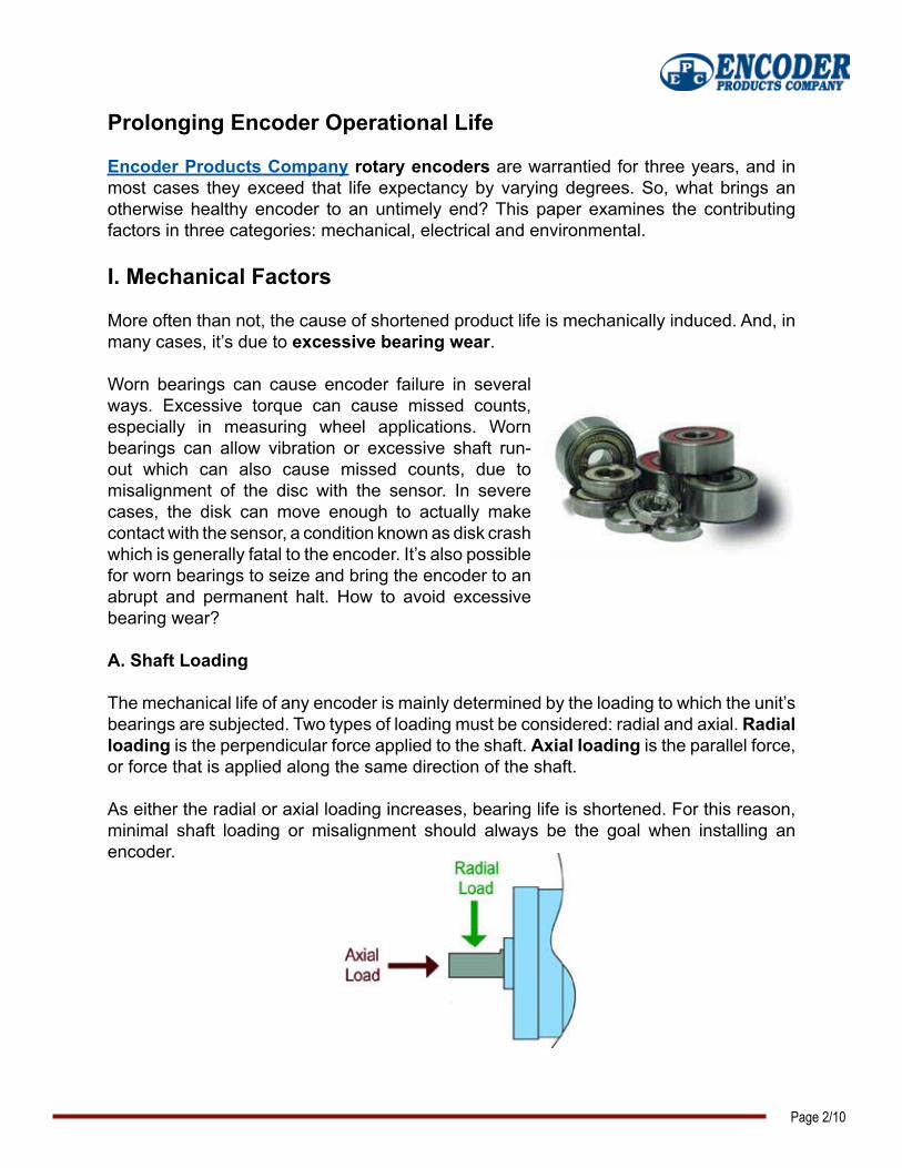
More often than not, the cause of shortened product life is mechanically induced. And, in many cases, it’s due to excessive bearing wear.
Worn bearings can cause encoder failure in several ways. Excessive torque can cause missed counts, especially in measuring wheel applications. Worn bearings can allow vibration or excessive shaft run-out which can also cause missed counts, due to misalignment of the disc with the sensor. In severe cases, the disk can move enough to actually make contact with the sensor, a condition known as disk crash which is generally fatal to the encoder. It’s also possible for worn bearings to seize and bring the encoder to an abrupt and permanent halt. How to avoid excessive bearing wear?
A. Shaft Loading
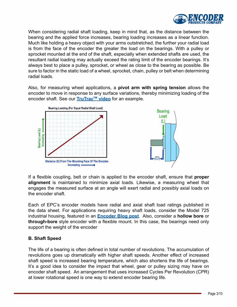
The mechanical life of any encoder is mainly determined by the loading to which the unit’s bearings are subjected. Two types of loading must be considered: radial and axial. Radial loading is the perpendicular force applied to the shaft. Axial loading is the parallel force, or force that is applied along the same direction of the shaft.
As either the radial or axial loading increases, bearing life is shortened. For this reason, minimal shaft loading or misalignment should always be the goal when installing an encoder.
Page 2/10
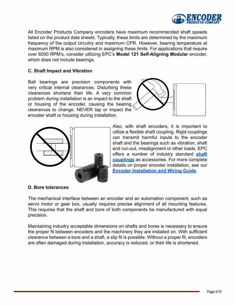
When considering radial shaft loading, keep in mind that, as the distance between the bearing and the applied force increases, bearing loading increases as a linear function. Much like holding a heavy object with your arms outstretched, the further your radial load is from the face of the encoder the greater the load on the bearings. With a pulley or sprocket mounted at the end of the shaft, especially when extended shafts are used, the resultant radial loading may actually exceed the rating limit of the encoder bearings. It’s always best to place a pulley, sprocket, or wheel as close to the bearing as possible. Be sure to factor in the static load of a wheel, sprocket, chain, pulley or belt when determining radial loads.
Also, for measuring wheel applications, a pivot arm with spring tension allows the encoder to move in response to any surface variations, thereby minimizing loading of the encoder shaft. See our TruTrac video for an example.
If a flexible coupling, belt or chain is applied to the encoder shaft, ensure that proper alignment is maintained to minimize axial loads. Likewise, a measuring wheel that engages the measured surface at an angle will exert radial and possibly axial loads on the encoder shaft.
Each of EPC’s encoder models have radial and axial shaft load ratings published in the data sheet. For applications requiring heavy shaft loads, consider the Model 725 industrial housing, featured in an Encoder Blog post. Also, consider a hollow bore or through-bore style encoder with a flexible mount. In this case, the bearings need only support the weight of the encoder
B. Shaft Speed
The life of a bearing is often defined in total number of revolutions. The accumulation of revolutions goes up dramatically with higher shaft speeds. Another effect of increased shaft speed is increased bearing temperature, which also shortens the life of bearings. It’s a good idea to consider the impact that wheel, gear or pulley sizing may have on encoder shaft speed. An arrangement that uses increased Cycles Per Revolution (CPR) at lower rotational speed is one way to extend encoder bearing life.
Page 3/10
TM
All Encoder Products Company encoders have maximum recommended shaft speeds listed on the product data sheets. Typically, these limits are determined by the maximum frequency of the output circuitry and maximum CPR. However, bearing temperature at maximum RPM is also considered in assigning these limits. For applications that require over 6000 RPM’s, consider utilizing EPC’s Model 121 Self-Aligning Modular encoder, which does not include bearings.
C. Shaft Impact and Vibration
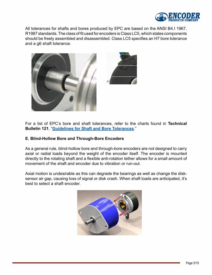
Ball bearings are precision components with very critical internal clearances. Disturbing these clearances shortens their life. A very common problem during installation is an impact to the shaft or housing of the encoder, causing the bearing clearances to change. NEVER tap or impact the encoder shaft or housing during installation.
Also, with shaft encoders, it is important to utilize a flexible shaft coupling. Rigid couplings can transmit harmful inputs to the encoder shaft and the bearings such as vibration, shaft end run-out, misalignment or other loads. EPC offers a number of industry standard shaft couplings as accessories. For more complete details on proper encoder installation, see our Encoder Installation and Wiring Guide.
D. Bore tolerances
The mechanical interface between an encoder and an automation component, such as servo motor or gear box, usually requires precise alignment of all mounting features. This requires that the shaft and bore of both components be manufactured with equal precision.
Maintaining industry acceptable dimensions on shafts and bores is necessary to ensure the proper fit between encoders and the machinery they are installed on. With sufficient clearance between a bore and a shaft, a slip fit is possible. Without a proper fit, encoders are often damaged during installation, accuracy is reduced, or their life is shortened.
Page 4/10
All tolerances for shafts and bores produced by EPC are based on the ANSI B4.I 1967, R1987 standards. The class of fit used for encoders is Class LC5, which states components should be freely assembled and disassembled. Class LC5 specifies an H7 bore tolerance and a g6 shaft tolerance.
For a list of EPC’s bore and shaft tolerances, refer to the charts found in Technical Bulletin 121, “Guidelines for Shaft and Bore Tolerances.”
E. Blind-Hollow Bore and Through-Bore Encoders
As a general rule, blind-hollow bore and through-bore encoders are not designed to carry axial or radial loads beyond the weight of the encoder itself. The encoder is mounted directly to the rotating shaft and a flexible anti-rotation tether allows for a small amount of movement of the shaft and encoder due to vibration or run-out.
Axial motion is undesirable as this can degrade the bearings as well as change the disk-sensor air gap, causing loss of signal or disk crash. When shaft loads are anticipated, it’s best to select a shaft encoder.
Page 5/10

II. Electrical Factors
Encoders are electromechanical devices. As such, problems in either area, electrical or mechanical, can lead to shortened product life. Most mechanical issues are more intuitive to identify and understand than electrical issues. However, a few simple precautions can reduce the odds that an electrical problem will doom your encoder.
A. Excessive Current
One sure way to transform your encoder into non-working hardware is to drive excessive current through the sensitive electronics. Avoiding this problem is often simply a matter of reviewing the encoder product specifications and comparing them to your supply power. Encoder Products Company encoders range from 80mA to 100mA current, with no output load. Specifications are listed on the product Data Sheet.
B. Interconnect
EPC invests significant time and effort when qualifying a new connector or cable for inclusion in our catalog of products. Reliable power supply and signal transmission require a reliable connection. Often customers, for reasons particular to their project or application, will opt to apply their own connector. While not part of the encoder itself, failure of the connector or cable produces the same net effect: loss of signal. Connectors are susceptible to vibration, strain, shock, temperature extremes and other factors. EPC qualifies our connectors to operate within product specifications for the life of our three year warranty. Therefore, whenever possible, we recommend using the EPC standard connectors. When replacing another brand of encoder with EPC, be sure to confirm wire color and pinout prior to installation.
C. Electrical Discharge Machining (EDM)
Electrical Discharge Machining (EDM) or fluting, as it is more commonly referred to, is the passage of electrical current through a bearing. When an electric current passes through a bearing, flowing between inner and outer rings via the rolling elements, damage will occur. Where the rolling elements contact the surface of the inner and outer rings, a process similar to electric arc welding occurs. The surface material is heated to temperatures ranging from tempering to melting levels. This leads to the appearance of discolored areas, varying in size, where the material has been tempered, re-hardened or melted. Small craters also form on the bearing surface where the metal has melted.
Page 6/10
For electric current to flow through a bearing, there must be a voltage potential and a path to ground. Current always takes the path with the least resistance. With a motor/encoder application, this often involves both the motor and the encoder bearings. The encoder bearings typically are damaged first since the smaller bearings are more susceptible to damage caused by EDM. Both alternating and direct currents cause damage to bearings.
Ideally, the source of shaft voltages and currents can be identified and corrective actions taken, but often it might not be possible or feasible to find or correct the source of the problem, even with a properly wired and grounded system. In this case either the shaft current can be rerouted to ground by installing a shaft grounding system or the current flow can be blocked by insulating the shaft from the bearings.
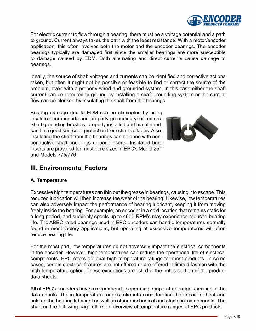
Bearing damage due to EDM can be eliminated by using insulated bore inserts and properly grounding your motors. Shaft grounding brushes, properly installed and maintained, can be a good source of protection from shaft voltages. Also, insulating the shaft from the bearings can be done with non-conductive shaft couplings or bore inserts. Insulated bore inserts are provided for most bore sizes in EPC’s Model 25T and Models 775/776.
III. Environmental Factors
A. Temperature
Excessive high temperatures can thin out the grease in bearings, causing it to escape. This reduced lubrication will then increase the wear of the bearing. Likewise, low temperatures can also adversely impact the performance of bearing lubricant, keeping it from moving freely inside the bearing. For example, an encoder in a cold location that remains static for a long period, and suddenly spools up to 4000 RPM’s may experience reduced bearing life. The ABEC-rated bearings used in EPC encoders can handle temperatures normally found in most factory applications, but operating at excessive temperatures will often reduce bearing life.
For the most part, low temperatures do not adversely impact the electrical components in the encoder. However, high temperatures can reduce the operational life of electrical components. EPC offers optional high temperature ratings for most products. In some cases, certain electrical features are not offered or are offered in limited fashion with the high temperature option. These exceptions are listed in the notes section of the product data sheets.
All of EPC’s encoders have a recommended operating temperature range specified in the data sheets. These temperature ranges take into consideration the impact of heat and cold on the bearing lubricant as well as other mechanical and electrical components. The chart on the following page offers an overview of temperature ranges of EPC products.
Page 7/10

Page 8/10
121225260755A15T/H15S70272575825T/H775776770771802S858S925958960SA/MA36MA63TR1TR2TR3LCECube
-40
-30
-20
-10 0 10 20 30 120
100908070605040
Temperature Ranges: EPC Encoders
B. Contamination
Foreign matter, whether in liquid or solid form, which infiltrates into the bearings, can cause rapid failure. Liquids can dilute or degrade the bearing lubricant, while abrasive materials, such as metal or carbon dust, are most damaging. Shaft seals help protect the bearings from the ingress of foreign substances. However, some extremely fine particulates can work their way into the shaft-seal interface, and given enough time, ingress into the bearing seal.
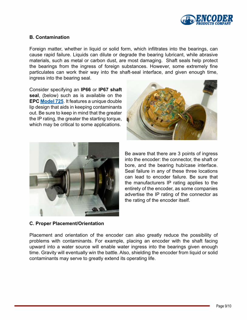
Consider specifying an IP66 or IP67 shaft seal, (below) such as is available on the EPC Model 725. It features a unique double lip design that aids in keeping contaminants out. Be sure to keep in mind that the greater the IP rating, the greater the starting torque, which may be critical to some applications.
Be aware that there are 3 points of ingress into the encoder: the connector, the shaft or bore, and the bearing hub/case interface. Seal failure in any of these three locations can lead to encoder failure. Be sure that the manufacturers IP rating applies to the entirety of the encoder, as some companies advertise the IP rating of the connector as the rating of the encoder itself.
C. Proper Placement/Orientation
Placement and orientation of the encoder can also greatly reduce the possibility of problems with contaminants. For example, placing an encoder with the shaft facing upward into a water source will enable water ingress into the bearings given enough time. Gravity will eventually win the battle. Also, shielding the encoder from liquid or solid contaminants may serve to greatly extend its operating life.
Page 9/10

D. Multiple Effects
It’s also important to realize that when multiple issues are present, such as high shaft loading at high speeds, bearing life can be significantly reduced. A certain amount of radial load with low temperatures and low rotational speeds might never cause a problem. However, the same amount of radial load with excessive temperatures and high shaft speeds will certainly affect the life expectancy of the bearings.
Conclusion
All of the factors mentioned can be present to one extent or another in industrial encoder applications and can shorten encoder life. As an encoder manufacturer, we take design measures to mitigate the adverse impacts of these factors on the encoder. For example, we offer sealed bearings, shaft seals and 80lbs rated bearings. However, before we manufacture the encoder, it’s even more important that the optimal encoder model and product features are specified. With proper specification, application and installation of rotary encoders, you’ll maximize the unit’s operational life. Some encoders have been running in applications non-stop for over 30 years, as noted on the Encoder Blog.
Of course, sometimes even the best engineered and designed encoder application can face unexpected challenges once it reaches the field. In one instance, we have witnessed factory maintenance workers using a shaft encoder as a step in order to reach an adjacent component.
For the record, Encoder Products Company does not recommend using the encoder as a step. Ever.
Page 10/10
You TubeContact us:

World HeadquartersAmericas Division
Encoder Products Company464276 Highway 95PO Box 249Sagle, Idaho 83860USA
Phone: 800-366-5412, 208-263-8541Fax: 208-263-0541E-mail: [email protected]: www.encoder.com
Asia Division
Zhuhai Precision Encoder Co., LTDRm. 308C, 3 / F, Zhongdian BuildingNo. 1082, JiuZhou Ave.Ji Da District, Zhuhai CityGuangdong Province, PRC519015
Phone: +86.756.3363470Fax: +86.756.3363573E-mail: [email protected]: www.asiaencoder.com
Europe Division
British Encoder Products CompanyWhitegate Industrial Estate, Unit 33Wrexham, ClwydWales LL13 8UGUnited Kingdom
Phone: +44.1978.262100Fax: +44.1978.262100E-mail: [email protected]: www.encoder.co.uk
World Wide Manufacturing Locations


