Page 1 of 11 Rev 3.1 Nov 2012 Document No. 147 IMPORTANT GUIDELINES Please read this instruction leaflet thoroughly before commencing installation. Ensure that that all the electrical installation is carried out by a fully qualified electrician and conforms to the appropriate Building Regulations and current IEEE Wiring Regulations. Ensure the heating system is protected via a suitable RCD device (30mA) protected circuit either locally or at the distribution board. Ensure the electrical supply can carry sufficient current to power the heating system (up to 16A). Fix the heating cable to the piping using the appropriate, fit for purpose, cable ties or adhesive tape (see page 6) Support the heating cable at 300mm (12") intervals or less. Ensure that all connections to the heating cable are sufficiently tight. Take care installing the system if the ambient temperature is below 5C because the cables become less flexible. Attach aluminium adhesive tape longitudinally over the heating cables when using with plastic piping (see page 6). Ensure the temperature probe is placed in an area which will be subject to ambient conditions. Ensure any cable glands used in the controller are of sufficient IP rating. Test the heating cable before attaching to the controller with a multimeter. Do not strain or cross over the heating cables. Do not supply power to the system until the cable has been completely unreeled and securely fastened in place. Do not install the temperature sensor close to other heat sources. Do not attempt to use the heating cable for a length of piping outside the recommended range as printed on the cable. Do not paint the heating cable. Do not bend the heating cable at right angles. The minimum bend radius is 1" or 25mm. Do not install the heating system until all pipe work has been completed and signed off in accordance with specifications. ProMinder Heating System Installation Instructions
Transcript
Page 1 of 11 Rev 3.1 Nov 2012Document No. 147
IMPORTANT GUIDELINESPlease read this instruction leaflet thoroughly before commencing installation.Ensure that that all the electrical installation is carried out by a fully qualified electrician and conforms to theappropriate Building Regulations and current IEEE Wiring Regulations.
Ensure the heating system is protected via a suitable RCD device (30mA) protected circuit either locally or atthe distribution board.
Ensure the electrical supply can carry sufficient current to power the heating system (up to 16A).
Fix the heating cable to the piping using the appropriate, fit for purpose, cable ties or adhesive tape(see page 6)
Support the heating cable at 300mm (12") intervals or less.
Ensure that all connections to the heating cable are sufficiently tight.
Take care installing the system if the ambient temperature is below 5C because the cables become less flexible.
Attach aluminium adhesive tape longitudinally over the heating cables when using with plastic piping(see page 6).
Ensure the temperature probe is placed in an area which will be subject to ambient conditions.
Ensure any cable glands used in the controller are of sufficient IP rating.
Test the heating cable before attaching to the controller with a multimeter.
Do not strain or cross over the heating cables.
Do not supply power to the system until the cable has been completely unreeled and securely fastened in place.
Do not install the temperature sensor close to other heat sources.
Do not attempt to use the heating cable for a length of piping outside the recommended range as printed on thecable.
Do not paint the heating cable.
Do not bend the heating cable at right angles. The minimum bend radius is 1" or 25mm.
Do not install the heating system until all pipe work has been completed and signed off in accordance withspecifications.
ProMinder Heating System Installation Instructions
Dan Macey
1
Page 2 of 11 Rev 3.1 Nov 2012Document No. 147
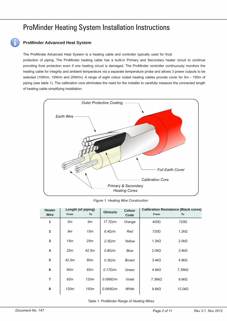
ProMinder Heating System Installation InstructionsProMinder Advanced Heat SystemThe ProMinder Advanced Heat System is a heating cable and controller typically used for frostprotection of piping. The ProMinder heating cable has a builtin Primary and Secondary heater circuit to continueproviding frost protection even if one heating circuit is damaged. The ProMinder controller continuously monitors theheating cable for integrity and ambient temperature via a separate temperature probe and allows 3 power outputs to beselected (10W/m, 15W/m and 20W/m). A range of eight colour coded heating cables provide cover for 5m 150m ofpiping (see table 1). The calibration core eliminates the need for the installer to carefully measure the connected lengthof heating cable simplifying installation.
Figure 1. Heating Wire ConstructionHeaterWire From To
ProMinder Heating System Installation Instructions
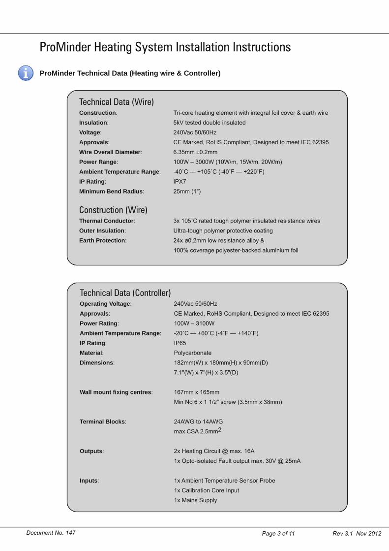
Technical Data (Controller)Operating Voltage: 240Vac 50/60HzApprovals: CE Marked, RoHS Compliant, Designed to meet IEC 62395Power Rating: 100W – 3100WAmbient Temperature Range: 20˚C — +60˚C (4˚F — +140˚F)IP Rating: IP65Material: PolycarbonateDimensions: 182mm(W) x 180mm(H) x 90mm(D)
7.1"(W) x 7"(H) x 3.5"(D)
Wall mount fixing centres: 167mm x 165mmMin No 6 x 1 1/2" screw (3.5mm x 38mm)
ProMinder Technical Data (Heating wire & Controller)
Page 4 of 11 Rev 3.1 Nov 2012Document No. 147
ProMinder System Installation PREPARATIONBefore installing the heating wire check the reel for damage which may have occurred during transport.Check the print legend on the heating wire is as expected and the heating range for this cable correspondsto the length of piping you intend to protect. Unpack the ProMinder controller and check it is not damaged.
The ProMinder heating wire must be laid in a loop on the pipework. This means there are two possibilitiesduring installation:
1. Both ends of the heating wire must be brought back to the ProMinder control unit.2. Both ends of the heating wire must be brought back to a separate junction box. A separate “cold lead” is
then run between the ProMinder controller and junction box connecting ALL coresA 7 core cable is required:
4 for the heating cores,2 for the calibration core &1 for the earth wire (the two ends may be commoned in the junction box)
If using a cold lead to join between the heating wire and the ProMinder controller the table below shows therecommended minimum copper equivalent cross sectional area (CSA) for the different heating cables.
Once it has been determined where the start and end of the heating wire will be the layout should beplanned and the best location of the reel to spool off the heating wire.
Before spooling off the heating wire an insulation resistance test should be performed using a standardinsulation resistance tester (such as a Megger). Applying a test potential of between 1000Vdc to 2500Vdcbetween each heater core and the earth wire and the calibration core and earth wire should read at least20Mohms.
The heating cable must be taken off the reel using a reel stand do not pull the heating cable off the reelsideways or from above with the reel laying flat.
ProMinder Heating System Installation Instructions
Minimum CSA(mm2) Heater Cable Pipework Length
0.75 1 – 3 5m – 25m
1.50 4 & 5 25m – 60m
2.5 6 – 8 60m – 150m
Table 2. Minimum CSA for Cold Lead
Page 5 of 11 Rev 3.1 Nov 2012Document No. 147
ProMinder Heating System Installation InstructionsINSTALLATION OF THE HEATING CABLEThe ProMinder heating cable should be installed in a continuous straightline along side the pipework. Run the heating cable along the bottom halfof the pipe. The outgoing run should be about a 1/3 of the way up on oneside and the return run shuold be a 1/3 of the way up on the other side(see figure 3).
The temperature probe should be installed so the tip is subject toambient temperature conditions and will not be affected by other heatsources. It is recommended to install the temperature probe such that itcan be functionally tested at regular intervals using a cold spray orequivalent method.
Figure 2. Example Layout of ProMinder Heating System
Figure 3. ProMinder HeatingCable placement on pipe
Page 6 of 11 Rev 3.1 Nov 2012Document No. 147
ProMinder Heating System Installation Instructions
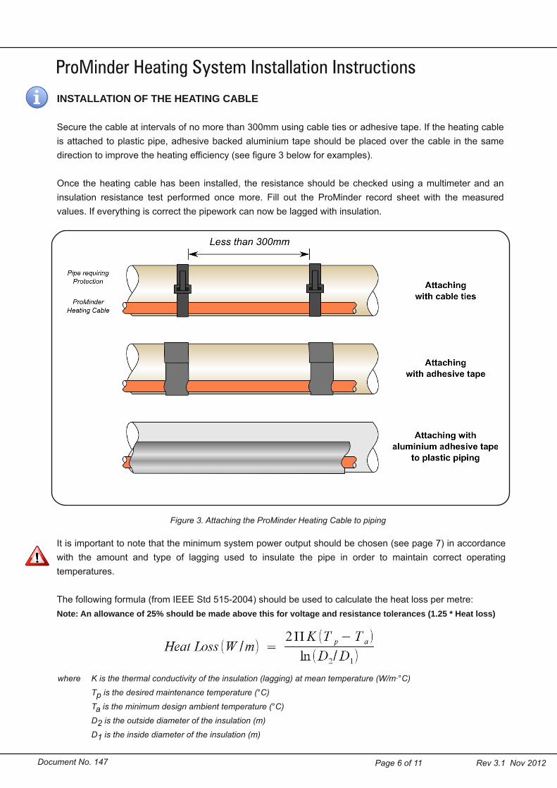
Figure 3. Attaching the ProMinder Heating Cable to piping
INSTALLATION OF THE HEATING CABLESecure the cable at intervals of no more than 300mm using cable ties or adhesive tape. If the heating cableis attached to plastic pipe, adhesive backed aluminium tape should be placed over the cable in the samedirection to improve the heating efficiency (see figure 3 below for examples).
Once the heating cable has been installed, the resistance should be checked using a multimeter and aninsulation resistance test performed once more. Fill out the ProMinder record sheet with the measuredvalues. If everything is correct the pipework can now be lagged with insulation.
It is important to note that the minimum system power output should be chosen (see page 7) in accordancewith the amount and type of lagging used to insulate the pipe in order to maintain correct operatingtemperatures.
The following formula (from IEEE Std 5152004) should be used to calculate the heat loss per metre:Note: An allowance of 25% should be made above this for voltage and resistance tolerances (1.25 * Heat loss)
where K is the thermal conductivity of the insulation (lagging) at mean temperature (W/m∙°C)Tp is the desired maintenance temperature (°C)Ta is the minimum design ambient temperature (°C)D2 is the outside diameter of the insulation (m)D1 is the inside diameter of the insulation (m)
Page 7 of 11 Rev 3.1 Nov 2012Document No. 147
ProMinder Heating System Installation InstructionsProMinder Control Unit PCB ConnectionsFigure 4 shows the typical connections to the PCB for the ProMinder System.
Connect the white cores of each heating cable to the Heater Circuit connector. A pair from the outgoing end ofthe heating wire should be wired into N1 and N2 and a pair from the return end of the heating wire should bewired into L1 and L2. It is NOT important which way round N1 & N2 or L1 & L2 are. Wire the black coresinto the Calibration Core (not polarity sensitive). The Temperature probe connection is not polarity sensitiveand is located on the left hand side of the PCB.
Ensure cable glands of the correct size (M20/M25/M32/M40) and IP rating (≥ IP65) are used where the cablesenter the enclosure. (Such as Lapp Cable Skintop® STRM 5311 1120 Gray or STRM 5311 1320 Black)
Figure 4. Typical PCB Connections for ProMinder
An external connection to a BMS or SCADA system can be made using the optoisolated fault output. This is useful for triggering a remote alarm/trouble signal andis polarity sensitive. Note: the optoisolated fault output has max. 30V 25mA rating
and is intended to switch endofline components for BMS systems etc.DO NOT CONNECT MAINS TO THE FAULT TERMINAL
Page 8 of 11 Rev 3.1 Nov 2012Document No. 147
ProMinder Control Unit INSTALLATIONThe ProMinder Control Unit montiors and provides power to a single zone of ProMinder Heating Cable. Twoseparate switching circuits ensure frost protection even in the event one heater circuit fails. The control unitconstantly monitors both circuits for a fault condition. When a fault occurs on a heating circuit the controllerautomatically switches to the other heater circuit. An light comes on in the controller displaying which circuithas a fault and the fault output changes state to remotely trigger a BMS/SCADA system if required.One of three power outputs may be selected for the heating wire: 10W/m, 15W/m and 20W/m (per metre ofpiping actual wire output is half as much). Before powering on the unit, select which power setting isrequired by sliding one of the DIP switches to the ON position.
The optoisolated fault output can be set to be normally off or normally conducting. The F marks which DIPswitch corresponds to the fault output setting. When the switch is in the NC position the fault output isnormally conducting and vice versa.Once the DIP switches have been set, power up the controller. The ProMinder controller enters a calibrationmode and checks to make sure the heating cable has been cut to the correct length (see table 1). If thelength is out of the acceptable range for this particular heating cable the PRI FAULT and SEC FAULT lightswill both light permanently.If the length is correct the controller then sets the correct power output for the cable. If a fault occurs at thispoint the PRI FAULT and SEC FAULT will flash alternatively. This indicates there is a problem deliveringpower to the heating cable. Check all connections are tight and the cable is the correct resistance.
ProMinder Heating System Installation Instructions
ProMinder Control Unit OPERATIONIn normal operation above approx +4˚C the power light will flash briefly. Every minute the controller will flashthe PRI HEAT and SEC HEAT light. This indciates the controller is checking the integrity of the heatingcircuits. If either heating circuit is faulty the corresponding PRI FAULT or SEC FAULT indicators will light andthe fault output will change state.When the temperature drops below approx +4˚C, if ok, the primary heater circuit will come on and thecontroller will flash the PRI HEAT light when power is being delivered. If the primary heater circuit is faulty,the secondary heater circuit will be used and the SEC HEAT light will flash.If at any time a fault occurs with the temperature probe, the PROBE FAULT light will light permanently.
Only one of the three heat setting DIP switches can be in the ON position at once. Ifthe DIP switches are not set correctly the unit will power up and immediately flash
the PROBE FAULT light on and off at 1s intervals.
If the temperature drops below 10˚C,the controller will boost power output by upto 50%.
The total boost in power output is limited by the length of heating element andpower output chosen at installation. Where the heating cable has been cut at themaximum length and the highest (20W/m) power output chosen the power boost
will not be available.
Page 9 of 11 Rev 3.1 Nov 2012Document No. 147
ProMinder Control Unit OPERATION AFTER POWER LOSSThe ProMinder Control unit stores the initial cable parameters in (nonvolatile) memory. In the event of apower loss to the controller, when power is restored the ProMinder control unit reads these parameters andpowers up without rechecking the cable length and power output of each cable. The state of the primaryand secondary circuit is also remembered such that if either circuit was in fault before power loss the faultwill still be present after power is restored. This allows for the ProMinder Heating System to be operationaleven if one circuit is has a fault and cannot be repaired immediately for some reason.For example, assume the ProMinder Heating System was installed with a 25m heating cable. At some pointthe primary circuit is damaged which causes the RCD or MCB supplying power to the system to trip. If arepair of the primary circuit cannot be carried out immediately, prior to resetting the RCD or MCB,disconnect the primary circuit from the ProMinder control unit. Upon resetting the RCD or MCB theProMinder will power up with the primary circuit in fault and automatically switch to the secondary circuitallowing heat to continue to be provided.If the ProMinder control unit is powered up with a circuit in fault condition this circuit is no longer checkedperiodically. Once the circuit is repaired to enable the circuit and automatic checking press the test buttonfor several seconds. The control unit will power the primary circuit briefly and check the correct poweroutput. If this test passes the fault light will extinguish and automatic checking will be reactivated.ProMinder Control Unit RESETTINGTo perform a reset of all stored settings, with the control unit off, switch the DIP switches into the resetposition (see below). The unit will power up and flash the all three FAULT lights. Once the fault lights areflashing, switch the power off and reset the DIP switches to the required heat output. The ProMinder controlunit will then recheck the cable length and power outputs as per the normal installation procedure.
ProMinder Heating System Installation Instructions
Figure 5. DIP Switch settings to RESET Control Unit
Page 10 of 11 Rev 3.1 Nov 2012Document No. 147
ProMinder Heating System Installation InstructionsProMinder Control Unit OPERATIONTable 3 shows the different possible light outputs for the ProMinder Control Unit. Make note whether thelights appear immediately after switch on or during normal operation (the green power light flashing) as thiswill aid troubleshooting.
Table 3. ProMinder Control Unit Light Descriptions
Page 11 of 11 Rev 3.1 Nov 2012Document No. 147
ProMinder Heating System Installation InstructionsProMinder Frequently Asked Questions1. Can the ProMinder Heating Cable be repaired if it has been damaged?Yes, the ProMinder Heating Cable can be repaired. If a small section (less than 300mm) is to be replacedthis can be done with a 4 core "cold lead" where each conductor has a sufficient cross sectional area (seepage 4). If more than 300mm is to be replaced this must be done with the same colour cable as is installed.Do not mix different colour cables together on the same circuit. Any joints between the cold lead and heatingcable, or between lengths of heating cable should be made in an IP65 or greater junction box with theappropriate cable glands.2. Can the ProMinder Heating Cable be extended?Yes, the ProMinder Heating Cable can be extended with the same colour cable as has been installed up tothe maximum length for that cable (see page 2). Any joints between lengths of heating cable should bemade in an IP65 or greater junction box with the appropriate cable glands.3. What is the best way to test the ProMinder system?The ProMinder controller automatically checks the heating cable for integrity however there are severalother tests which can be performed to ensure the system is functioning correctly. The temperature probecan be checked by reducing the temperature at the tip to less than +5˚C. This can be done using a coldspray or equivalent method. If the system is working correctly the primary heater circuit should activate oncethe probe drops below this temperature.Within the ProMinder controller is a test button (see page 7) which forces the controller to activate theheater circuits. Holding this button down should briefly activate the primary circuit and then the secondarycircuit. This will repeat as long as the button is held down. The current flowing through each heating circuitis checked by the controller when the test button is pressed. If the measured current is outside the cablespecification the corresponding fault indicator will light. After 1 to 2 minutes of continuously holding the testbutton the cable should be noticeably warmer than ambient conditions.4. Can standard ProMinder Heating Cable be used on PVC pipes?Yes, ProMinder Heating Cable can be used to provide frost protection on uPVC and similar piping with norisk of plasticizer migration. The outer sheath material used on the ProMinder Heating Cable has beencarefully chosen to minimise any reaction with other plastics.