INTERNATIONAL JOURNAL of RENEWABLE ENERGY RESEARCH Susastriawan et al., Vol.9, No.1, 2019 Propagation Characteristic and Performance of Rice Husk Gasification at Different Tuyer Inclination Angle A.A.P. Susastriawan* ‡ , Harwin Saptoadi*, Purnomo* * Dept. of Mechanical and Industrial Engineering, Faculty of Engineering, Universitas Gadjah Mada, Indonesia [email protected]; [email protected]; [email protected]‡ Corresponding Author; A.A.P. Susastriawan, Dept.of Mechanical Engineering, Institut Sains & Teknologi AKPRIND, Jl, Kalisahak No. 28 Komplek Balapan, Yogyakarta 55222, Indonesia, [email protected]Received: 20.10.2018 Accepted:18.11.2018 Abstract- Although several works on rice husk gasification in downdraft gasifier have been reported, but none of those works investigated and discussed propagation and performance of the gasification at different tuyer inclination angle. The present work aims to investigate an effect of tuyer inclination angle on propagation characteristic and performance of the gasifier fed by rice husk. Gasification of rice husk is performed in small-scale closed top downdraft gasifier at tuyer inclination angle of 0 ° , 30 ° and 60 ° and at equivalence ratio of 0.20. The tuyers are located at 400 mm above the grate. The highest burning propagation rate and effective propagation rate are achieved at tuyer inclination angle of 0 ° . The values are 0.29 and 0.44 mm/s respectively. The highest higher heating value of producer gas of 3.24 MJ/Nm 3 and the highest cold gas efficiency of 78.39% are also found at tuyer inclination angle of 0 ° . Keywords: gasification, inclination angle, propagation, performance, rice husk. 1. Introduction From many sources of renewable energy, biomass is one of the most promising sources that can be applied for heat generation as well as for electricity generation [1]. According to process followed, biomass conversion is divided into two routes, biological route and thermal route [2]. Biogas production from Olive-mill waste [3] is an example of biological route of biomass energy conversion. Meanwhile, one of well-known thermal route is biomass gasification. Gasification takes place in reactor called gasifier. In downdraft gasifier, burning front moves in opposite direction with feedstock bed and gasification air. Feedstock is initiated through ignition port at lower part of the reactor and air is supplied via tuyer at upper part of the reactor. As gasification proceeds, burning front moves upward and gasification air along with feedstock move downward in the reactor. Product of gasification, “producer gas”, exits at lower part of the reactor. The opposite movement between burning front and gasification air is defined as reverse propagation [4] and [5]. Upward burning and downward feedstock velocities are termed as burning propagation and bed propagation rate, respectively [4], [6], and [7]. Figure 1 shows schematic diagram of burning propagation in downdraft gasifier. Several works on propagation of solid fuel combustion as well as gasification including biomass fuel have been reported. For gasification regime, propagation front has been investigated by [8], [9], [10], and [7]. Burning front velocity and biomass consumption rate accelerate with increasing air flow rate [10]. With increasing air flow rate, amount of oxygen increases. Higher oxygen content enhances and oxidation rate. Burning front propagates faster as increasing oxidation rate and consumed more feedstock. The burning propagation rate is obtained from the time required to reach particular reference temperature between two locations along the vertical axis of the gasifier. Depend on midpoint in positive slope of temperature profile, different reference temperatures have been used for obtaining burning propagation rate, such as 400 ° C [11] and 500 ° C [4] and [6]. Meanwhile, bed propagation rate is calculated from the downward distance of the feedstock at any given time. The distance is obtained by subtraction of initial height and final height of fuel bed. The sum between flame propagation and
Abstract- Although several works on rice husk gasification in downdraft gasifier have been reported, but none of those works investigated and discussed propagation and performance of the gasification at different tuyer inclination angle. The present work aims to investigate an effect of tuyer inclination angle on propagation characteristic and performance of the gasifier fed by rice husk. Gasification of rice husk is performed in small-scale closed top downdraft gasifier at tuyer inclination angle of 0°, 30° and 60° and at equivalence ratio of 0.20. The tuyers are located at 400 mm above the grate. The highest burning propagation rate and effective propagation rate are achieved at tuyer inclination angle of 0°. The values are 0.29 and 0.44 mm/s respectively. The highest higher heating value of producer gas of 3.24 MJ/Nm3 and the highest cold gas efficiency of 78.39% are also found at tuyer inclination angle of 0°.
From many sources of renewable energy, biomass is one of the most promising sources that can be applied for heat generation as well as for electricity generation [1]. According to process followed, biomass conversion is divided into two routes, biological route and thermal route [2]. Biogas production from Olive-mill waste [3] is an example of biological route of biomass energy conversion. Meanwhile, one of well-known thermal route is biomass gasification. Gasification takes place in reactor called gasifier. In downdraft gasifier, burning front moves in opposite direction with feedstock bed and gasification air. Feedstock is initiated through ignition port at lower part of the reactor and air is supplied via tuyer at upper part of the reactor. As gasification proceeds, burning front moves upward and gasification air along with feedstock move downward in the reactor. Product of gasification, “producer gas”, exits at lower part of the reactor. The opposite movement between burning front and gasification air is defined as reverse propagation [4] and [5]. Upward burning and downward feedstock velocities are termed as burning
propagation and bed propagation rate, respectively [4], [6], and [7]. Figure 1 shows schematic diagram of burning propagation in downdraft gasifier.
Several works on propagation of solid fuel combustion as well as gasification including biomass fuel have been reported. For gasification regime, propagation front has been investigated by [8], [9], [10], and [7]. Burning front velocity and biomass consumption rate accelerate with increasing air flow rate [10]. With increasing air flow rate, amount of oxygen increases. Higher oxygen content enhances and oxidation rate. Burning front propagates faster as increasing oxidation rate and consumed more feedstock.
The burning propagation rate is obtained from the time required to reach particular reference temperature between two locations along the vertical axis of the gasifier. Depend on midpoint in positive slope of temperature profile, different reference temperatures have been used for obtaining burning propagation rate, such as 400°C [11] and 500°C [4] and [6]. Meanwhile, bed propagation rate is calculated from the downward distance of the feedstock at any given time. The distance is obtained by subtraction of initial height and final height of fuel bed. The sum between flame propagation and
bed propagation rate is defined as effective propagation rate [4].
Fig. 1. Schematic diagram of burning propagation in downdraft gasifier
Performance of the downdraft gasifier is indicated by higher heating value of producer gas and cold gas efficiency. The performance of the gasifier can be affected by several factors, such as location of air tuyer above the grate and equivalence ratio. Effect of air tuyer location above the grate on performance of downdraft gasifier has been simulated by [12] and [13]. Height of gasification zone rose as increasing tuyer distance above the grate. Increasing reduction zone resulted in longer residence time of pyrolysis product in reduction zone, thus Water-Gas and Bouduard reactions occurred effectively and produced more CO and H2. Increasing CO and H2 in producer gas improved higher heating value of producer gas and cold gas efficiency as well. However, some works have been focused only on production of hydrogen from biomass instead of producer gas [14]–[16]
According to Basu [17], combustible gas CO, H2, and CH4 are formed through endothermic as well as exothermic reactions during reduction process as follows Water-Gas:
kJ/molHCOOHC 13122 ++→+ (1) Bouduard:
kJ/molCOCOC 17222 +→+ (2) Water-Gas Shift:
kJ/mol.HCOOHCO 241222 −+→+ (3) Methane Formation:
kJ/mol.CHHC 8742 42 −→+ (4)
Reed & Das [18] defined equivalence ratio as the ratio between actual air flow rate used in gasification to stoichiometric air flow rate for complete combustion. Meanwhile Kaupp & Goss [19], stated that typically equivalence ratio is 0.2 to 0.4 for effective gasification. When equivalence ratio lower than 0.20, pyrolysis dominates
during gasification. In contrast, combustion will dominate when equivalence ratio is higher than 0.4 [20]. Equivalence ratio is proportional to oxidation rate [21] and biomass consumption rate [22]. More oxygen is available in higher equivalence ratio, results in improving oxidation rate in oxidation zone. Higher oxidation rate consumes more feedstock, hence increases biomass consumption rate. Besides, gasification temperature also escalates as enhancing oxidation rate. The effect of equivalence ratio on performance of small-scale closed top downdraft gasifier fed by rice husk has been reported in Susastriawan [23]. Maximum cold gas efficiency was achieved at equivalence ratio of 0.2 where gasification air is supplied via horizontal tuyer located at 400 mm above the grate. The gasifier has a diameter of 300 mm and height of 725 mm. The performance of the gasifier in term of flame continuity of producer gas in flare was also compared with other gasifier whose diameter of 300 mm and height of 950 mm [24].
Although several works have been performed regarding
rice husk gasification, but none of the works have discussed effect of tuyer inclination angle on propagation behavior and performance of the gasifier. Besides equivalence ratio and air inlet location, tuyer inclination angle controls air flow pattern when passing through the fuel bed. Tuyer inclination angle may also influence contact time between the feedstock and the air which may affect the propagation characteristic, and in turn the performance of the gasifier. In present work, gasification of rice husk in small-scale closed top downdraft gasifier is performed at different tuyer inclination angles of 0°, 30°, and 60°. The work aims to investigate the effect of the tuyer inclination angle on the propagation characteristic and the performance of the gasifier
2. Material and Method
2.1. Feedstock characterization Feedstock of rice husk used in this work is obtained
from paddy milling industry in Bantul, Yogyakarta, Indonesia. Result of proximate, ultimate, and higher heating value are given in Table 1 at the end of this section.
2.2. Experimental work
The experimental work is performed at the Laboratory of Energy Conversion, Department of Mechanical and Industrial Engineering, Faculty of Engineering, Universitas Gadjah Mada, Indonesia. Figure 2(a) displays a photo of experimental setup which consists of downdraft reactor, blower, suction fan, flare, and measurement devices. Meanwhile, Fig. 2(b) presents schematic diagram of tuyer location and inclination angle. The reactor has a diameter of 300 mm, height (from grate to top) of 725 mm. The reactor has five stages tuyer which are located at 120, 190,260, 330, and 400 mm above the grate. The tuyer has a diameter of 1 inch. In order to show better view of tuyer location and orientation, only 1st stage tuyer (120 mm above the grate) and 5th stage tuyer (440 mm above the grate) are shown in Fig. 2(b). Three tuyers in the 1st stage are used as ignition port. Gasification is initiated via the tuyers in the 1st stage.
Meanwhile, nine tuyers are available in the 5th stage for supplying air during gasification. Three tuyers (red color) has inclination angle (α) of 0°, three tuyers (black color) has α of 30°, and the rest (blue color) has α of 60°.
Rice husk gasification is conducted at equivalence ratio
of 0.2 for α of 0°, 30°, and 60°. 5 kg of rice husk is fed into the reactor. To meet the equivalence ratio of 0.2 for 5 kg of rice husk, actual air flow rate required is 4.2 m3/h. Since air is supplied through three tuyers for each α, thus air flow rate of 1.4 m3/h is set for each tuyer. During gasification, temperatures at location of 50 mm (T1), 120 mm (T2), 190 mm (T3), 260 mm (T4), and 330 mm (T5) above the grate are measured with K-type thermocouples that connected to data logger (OMRON ZR-RX45). Three samples of producer gas
are taken every 10 minutes for each run and analyzed using Gas Chromatograph (SHIMADZU GC-8A) at Department of Chemical Engineering in the same University. Once volume fraction of CO, H2, and CH4 are obtained, higher heating value of producer gas and cold gas efficiency are calculated. Time required to reach the reference temperature between two thermocouples is obtained from temperature profiles during gasification. Meanwhile, the distance travelled by the feedstock is obtained by subtraction of initial height and final height of lever rod at starting time and at the end of gasification, respectively.
Table 1. Proximate, ultimate, gross heating value analysis of the rice husk
3.1. Temperature profile Figure 3 shows effects of tuyer inclination angle (α) on
profile of axial temperature of the reactor during 30 minutes gasification. For all α analyzed, temperature T1 increases firstly, then followed by increasing temperature of T2, T3, T4, and T5. This indicates that burning front moves downward in early stage of gasification. Oxidation occurs at the location near to the grate, thus the temperature at 50 mm above the grate (T1) increases. When fresh feedstock at the location is completely oxidized, burning front moves upward to the fresh feedstock at higher locations, i.e. 120, 190, 260, 300 mm above the grate. Hence the temperature of T2, T3, T4, and T5 increase later.
Fig. 3. Effect of tuyer inclination angle on profile of axial temperature
The rising of axial temperature is faster for horizontal tuyer than for inclined tuyer. Uniform air distribution to the feedstock with the use of horizontal tuyer improves oxidation
rate and heat released. Higher oxidation rate for horizontal tuyer results in higher axial temperature as shown in Fig.3. In contrast, non-uniform air distribution for inclined tuyer leads to uneven oxidation across sectional area of the reactor, thus reduces heat released. Uneven oxidation at cross sectional area of the reactor with the use of inclined tuyer is indicated by axial temperatures which is more fluctuate during gasification as can be observed in Fig.3. The fluctuation also due to air stream moves toward the bottom of the reactor for inclined tuyer. After a certain time, the stream contacts with feedstock in fuel channel and burns a channel into the hot fuel bed. The channel will collapse and lead to temperature alteration. This phenomena are called channeling and bridging. Channeling and bridging may reduce performance of the gasifier. Beside, bridging may affect measurement error during experimental work. Significant statistical deviation occurred when bridging is found during gasification [25]
3.2. Propagation characteristic
Figure 4 presents effect of α on burning, bed, and effective propagation rates. Burning front propagates upward to the fresh feedstock, whereas feedstock moves downward. Summation between the two is defined as effective propagation rate. As been discussed earlier, uniform air distribution to the feedstock for horizontal tuyer improves oxidation and burning propagation rates. Burning propagation rates at α 0o, 30o, and 60o are 0.29, 0.12, and 0.16 mm/s, respectively. Although burning propagation rate is higher, but bed propagation rate is lower for horizontal tuyer. Since burning propagation rate is high, oxidation front moves faster to the fresh feedstock above and left highest reduction zone. Highest reduction zone means more char in the zone, results in reduction of downward velocity of the fresh feedstock. Hence, bed propagation rate is lower for horizontal tuyer as indicated in Fig.4. The bed propagation rates are 0.16, 0.21, and 0.21 mm/s for α 0°, 30°, and 60°, accordingly. The highest effective propagation rate of 0.44 mm/s is observed for horizontal tuyer (α 0°). Meanwhile, the values at α 30° and 60° are 0.33 and 0.37 mm/s, respectively.
Fig. 4. Effect of tuyer inclination angle on propagation rate
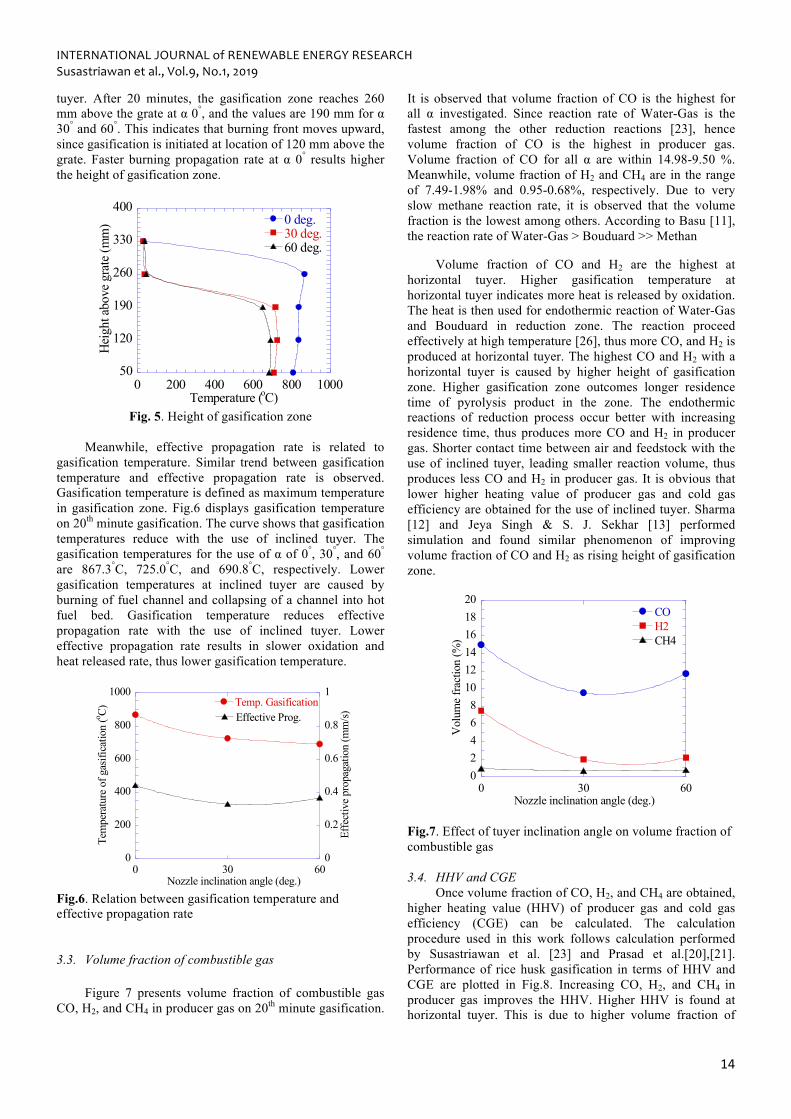
Burning propagation rate affects height of gasification
zone during rice husk gasification. As shown in Fig.5, gasification zone is higher for horizontal tuyer than inclined
tuyer. After 20 minutes, the gasification zone reaches 260 mm above the grate at α 0°, and the values are 190 mm for α 30° and 60°. This indicates that burning front moves upward, since gasification is initiated at location of 120 mm above the grate. Faster burning propagation rate at α 0° results higher the height of gasification zone.
0 200 400 600 800 100050
120
190
260
330
4000 deg.30 deg.60 deg.
Temperature (oC)
Hei
ght a
bove
gra
te (m
m)
Fig. 5. Height of gasification zone
Meanwhile, effective propagation rate is related to
gasification temperature. Similar trend between gasification temperature and effective propagation rate is observed. Gasification temperature is defined as maximum temperature in gasification zone. Fig.6 displays gasification temperature on 20th minute gasification. The curve shows that gasification temperatures reduce with the use of inclined tuyer. The gasification temperatures for the use of α of 0°, 30°, and 60° are 867.3°C, 725.0°C, and 690.8°C, respectively. Lower gasification temperatures at inclined tuyer are caused by burning of fuel channel and collapsing of a channel into hot fuel bed. Gasification temperature reduces effective propagation rate with the use of inclined tuyer. Lower effective propagation rate results in slower oxidation and heat released rate, thus lower gasification temperature.
0
200
400
600
800
1000
0
0.2
0.4
0.6
0.8
1
0 30 60
Temp. GasificationEffective Prog.
Tem
pera
ture
of g
asifi
catio
n (o C)
Effe
ctiv
e pro
paga
tion
(mm
/s)
Nozzle inclination angle (deg.) Fig.6. Relation between gasification temperature and effective propagation rate 3.3. Volume fraction of combustible gas
Figure 7 presents volume fraction of combustible gas CO, H2, and CH4 in producer gas on 20th minute gasification.
It is observed that volume fraction of CO is the highest for all α investigated. Since reaction rate of Water-Gas is the fastest among the other reduction reactions [23], hence volume fraction of CO is the highest in producer gas. Volume fraction of CO for all α are within 14.98-9.50 %. Meanwhile, volume fraction of H2 and CH4 are in the range of 7.49-1.98% and 0.95-0.68%, respectively. Due to very slow methane reaction rate, it is observed that the volume fraction is the lowest among others. According to Basu [11], the reaction rate of Water-Gas > Bouduard >> Methan
Volume fraction of CO and H2 are the highest at horizontal tuyer. Higher gasification temperature at horizontal tuyer indicates more heat is released by oxidation. The heat is then used for endothermic reaction of Water-Gas and Bouduard in reduction zone. The reaction proceed effectively at high temperature [26], thus more CO, and H2 is produced at horizontal tuyer. The highest CO and H2 with a horizontal tuyer is caused by higher height of gasification zone. Higher gasification zone outcomes longer residence time of pyrolysis product in the zone. The endothermic reactions of reduction process occur better with increasing residence time, thus produces more CO and H2 in producer gas. Shorter contact time between air and feedstock with the use of inclined tuyer, leading smaller reaction volume, thus produces less CO and H2 in producer gas. It is obvious that lower higher heating value of producer gas and cold gas efficiency are obtained for the use of inclined tuyer. Sharma [12] and Jeya Singh & S. J. Sekhar [13] performed simulation and found similar phenomenon of improving volume fraction of CO and H2 as rising height of gasification zone.
02468
101214161820
0 30 60
COH2CH4
Vol
ume
fract
ion
(%)
Nozzle inclination angle (deg.)
Fig.7. Effect of tuyer inclination angle on volume fraction of combustible gas
3.4. HHV and CGE
Once volume fraction of CO, H2, and CH4 are obtained, higher heating value (HHV) of producer gas and cold gas efficiency (CGE) can be calculated. The calculation procedure used in this work follows calculation performed by Susastriawan et al. [23] and Prasad et al.[20],[21]. Performance of rice husk gasification in terms of HHV and CGE are plotted in Fig.8. Increasing CO, H2, and CH4 in producer gas improves the HHV. Higher HHV is found at horizontal tuyer. This is due to higher volume fraction of
CO, H2, and CH4 as previously shown in Fig 7. The HHVs at α of 0°, 30°, and 60° are 3.24, 1.73, and 2.07 MJ/Nm3. Similar trend between HHV and CGE is observed. The CGE are 78.39, 51.73, and 55.30% at α of 0°, 30°, and 60°, respectively. The highest CGE is achieved at the highest HHV for the use of horizontal tuyer. Based on CGE, the performance of the gasifier fed by rice husk is maximum for horizontal tuyer. More uniform axial temperature during gasification at α of 0o as shown in Fig. 3 results in higher CGE. As stated by Belonio [29], uniform axial temperature during gasification increases performance of gasifier.
Fig.8. Effect of tuyer inclination angle on HHV and CGE
4. Conclusion
It can be concluded that tuyer inclination angle affects propagation characteristic and performance of rice husk gasification in small-scale closed top downdraft gasifier. Higher propagation rates, gasification zone, and volume fraction of combustible gas, higher heating value of producer gas, and cold gas efficiency are found with the use of horizontal tuyer. Meanwhile, shorter contact time between air and feedstock with the use of inclined tuyer, leads smaller reaction volume and produces less CO and H2 in producer gas. It is obvious that smaller HHV of producer gas and CGE are obtained for the use of inclined tuyer.
For rice husk gasification in this work, it can be stated that optimum performance of the gasifier is obtained for the use of tuyer inclination angle of 0° (horizontal tuyer). At tuyer inclination angle of 0°, the highest HHV of 3.24 MJ/Nm3 and the highest CGE of 78.39 are obtained. The volume fraction of CO, H2 and CH4 at this tuyer inclination angle are found to be 14.98%, 7.49%, and 0.95%, respectively.
Acknowledgements
The authors are grateful to DRPM-Kemenristekdikti (Ministry of Research, Technology, and Higher Education)- Republic of Indonesia for financial support under the scheme of Hibah Penelitian Disertasi Doktor 2018 (DIPA-042.06.0.1.401516/2018; No:109/SP2H/LT/DRPM/2018)
.
References
[1] I. Carlucci, G. Mutani, and M. Martino, “Assessment of potential energy producible from agricultural biomass in the municipalities of the Novara plain,” 2015 Int. Conf. Renew. Energy Res. Appl. ICRERA 2015, vol. 5, pp. 1394–1398, 2015.
[2] S. Mohapatra and K. Gadgil, “Biomass: The Ultimate Source of Bio Energy,” Int. J. Renew. Energy Res., vol. 3, no. 1, pp. 2–5, 2013.
[3] Y. Ulusoy and A. H. Ulukardesler, “Biogas production potential of olive-mill wastes in Turkey,” 2017 6th Int. Conf. Renew. Energy Res. Appl. ICRERA 2017, vol. 2017–January, pp. 664–668, 2017.
[4] S. Mahapatra and S. Dasappa, “Experiments and analysis of propagation front under gasification regimes in a packed bed,” Fuel Process. Technol., vol. 121, no. April 2016, pp. 83–90, 2014.
[5] M. S. Blinderman, D. N. Saulov, and A. Y. Klimenko, “Forward and reverse combustion linking in underground coal gasification,” Energy, vol. 33, no. 3, pp. 446–454, 2008.
[6] S. Mahapatra, S. Kumar, and S. Dasappa, “Gasification of wood particles in a co-current packed bed: Experiments and model analysis,” Fuel Process. Technol., vol. 145, pp. 76–89, 2016.
[7] P. M. Gnanendra and N. K. S. Rajan, “Experimental Study on Performance of Downdraft Gasifier Reactor under Varied Ratios of Secondary and Primary Air Flows,” Energy Procedia, vol. 90, no. December 2015, pp. 38–49, 2016.
[8] S. Mahapatra and S. Dasappa, “Experiments and analysis of propagation front under gasification regimes in a packed bed,” Fuel Process. Technol., vol. 121, no. May 2014, pp. 83–90, 2014.
[9] S. Mahapatra, S. Kumar, and S. Dasappa, “Gasification of wood particles in a co-current packed bed: Experiments and model analysis,” Fuel Process. Technol., vol. 145, pp. 76–89, 2016.
[10] Y. A. Lenis, J. F. Pérez, and A. Melgar, “Fixed bed gasification of Jacaranda Copaia wood: Effect of packing factor and oxygen enriched air,” Ind. Crops Prod., vol. 84, pp. 166–175, 2016.
[11] J. F. Pérez, A. Melgar, and P. N. Benjumea, “Effect of operating and design parameters on the gasification/combustion process of waste biomass in fixed bed downdraft reactors: An experimental study,” Fuel, vol. 96, pp. 487–496, 2012.
[12] A. K. Sharma, “Equilibrium and kinetic modeling of char reduction reactions in a downdraft biomass gasifier : A comparison,” vol. 82, pp. 918–928, 2008.
[13] V. C. Jeya Singh and S. J. Sekhar, “Performance studies on a downdraft biomass gasifier with blends of coconut shell and rubber seed shell as feedstock,” Appl. Therm. Eng., vol. 97, pp. 22–27, 2016.
[14] S. Kaya, B. Ozturk, and H. Aykac, “Hydrogen production from renewable source: Biogas,” Proc. 2013 Int. Conf. Renew. Energy Res. Appl. ICRERA 2013, no. October 2013, pp. 633–637, 2013.
[15] O. Nakagoe, Y. Furukawa, S. Tanabe, Y. Sugai, and R. Narikiyo, “Hydrogen production from steam reforming of woody biomass with cobalt catalyst,” 2012 Int. Conf. Renew. Energy Res. Appl. ICRERA 2012, pp. 2–5, 2012.
[16] M. Aziz, T. Oda, T. Mitani, A. Uetsuji, and T. Kashiwagi, “Combined hydrogen production and power generation from microalgae,” 2015 Int. Conf. Renew. Energy Res. Appl. ICRERA 2015, vol. 5, pp. 923–927, 2015.
[17] P. Basu, Biomass Gasification and Pyrolysis. Pratical Design. 2010.
[18] T. B. Reed and A. Das, “Handbook of biomass downdraft gasifier engine systems,” no. March, 1988.
[19] A. Kaupp and J. R. Goss, “State of the art report for small scale (to 50 kW) gas producer - engine systems,” no. 53, p. 286, 1981.
[20] H. Olgun, S. Ozdogan, and G. Yinesor, “Results with a bench scale downdraft biomass gasifier for agricultural and forestry residues,” Biomass and Bioenergy, vol. 35, no. 1, pp. 572–580, 2011.
[21] F. Guo, Y. Dong, L. Dong, and C. Guo, “Effect of design and operating parameters on the gasification process of biomass in a downdraft fixed bed: An experimental study,” Int. J. Hydrogen Energy, vol. 39, no. 11, pp. 5625–5633, 2014.
[22] F. V Tinaut, A. Melgar, J. F. Pérez, and A. Horrillo,
“Effect of biomass particle size and air superficial velocity on the gasification process in a downdraft fixed bed gasifier . An experimental and modelling study,” 2008.
[23] A. A. P. Susastriawan, H. Saptoadi, and Purnomo, “Design and experimental study of pilot scale throat-less downdraft gasifier fed by rice husk and wood sawdust,” Int. J. Sustain. Energy, vol. 37, no. 9, 2018.
[24] A. A. P. Susastriawan, H. Saptoadi, and Purnomo, “Comparative study of two small-scale downdraft gasifiers in terms of continuous flammability duration of producer gas from rice husk and sawdust gasification,” Int. J. Renew. Energy Res., vol. 7, no. 3, 2017.
[25] S. Sarker and H. K. Nielsen, “Assessing the gasification potential of five woodchips species by employing a lab-scale fixed-bed downdraft reactor,” Energy Convers. Manag., vol. 103, pp. 801–813, 2015.
[26] C. Gai and Y. Dong, “Experimental study on non-woody biomass gasification in a downdraft gasifier,” Int. J. Hydrogen Energy, vol. 37, no. 6, pp. 4935–4944, 2012.
[27] L. Prasad, P. M. V. Subbarao, and J. P. Subrahmanyam, “Pyrolysis and gasification characteristics of Pongamia residue (de-oiled cake) using thermogravimetry and downdraft gasifier,” Appl. Therm. Eng., vol. 63, no. 1, pp. 379–386, 2014.
[28] L. Prasad, P. M. V. Subbarao, and J. P. Subrahmanyam, “Experimental investigation on gasification characteristic of high lignin biomass (Pongamia shells),” Renew. Energy, vol. 80, pp. 415–423, 2015.
[29] A. T. Belonio, “Rice Husk Gas Stove Handbook,” Bioenergylists.Org, 2005.