Propagation of aberrations through phase-inducedamplitude apodization coronagraph
Laurent Pueyo,1,2,* N. Jeremy Kasdin,3 and Stuart Shaklan4
1Johns Hopkins University, Department of Physics and Astronomy, 366 Bloomberg Center 3400 N. Charles Street,Baltimore, Maryland 21218, USA
2Space Telescope Science Institute, 3700 San Marin Drive, Baltimore, Maryland 21218, USA3Department of Mechanical and Aerospace Engineering, Princeton University, Princeton, New Jersey 08544, USA
4Jet Propulsion Laboratory, California Institute of Technology, 4800 Oak Grove Drive, Pasadena, California 91109, USA*Corresponding author: [email protected]
Received March 23, 2010; revised October 8, 2010; accepted October 11, 2010;posted November 11, 2010 (Doc. ID 125848); published January 24, 2011
1. INTRODUCTIONAnalytical propagation of wavefront errors through corona-graphs is the basis of all the recent error budget estimatesfor both ground- and space-based exoplanet imaging instru-ments. The literature has been particularly active in this area,and our understanding of the sensitivity to aberrations of sev-eral coronagraphic solutions has considerably expanded overthe past few years. For band-limited coronagraphs, Sivara-makrishnan et al. [1] first introduced an analytical propagatorfor low-order modes based on a Zernike decomposition. Inparallel, Shaklan and Green [2] carried out the same analysisfor mid-spatial frequencies, based on a Fourier decomposi-tion, comparing the sensitivities of band-limited corona-graphs. Perrin et al. [3] studied the impact of second-orderterms on the point spread function, a result revisited and for-malized by Give’On et al. [4], who introduced the concept offrequency folding. Sivaramakrishnan et al. [5] then focused onthe propagation of mid-spatial frequencies through apodizedpupil Lyot coronagraphs. The case of out-of-pupil optics andthe resultant chromatic phase to amplitude mixing was firsttackled by Shaklan et al. [6] for band-limited and shaped pupilcoronagraphs, and we recently provided a formal analyticalapproach that addresses this issue in Pueyo and Kasdin [7].
Computing the sensitivity to aberrations proves to be amore challenging task in the case of phase-induced amplitudeapodization (PIAA) coronagraphs and for the optical vectorialvortex coronagraph (OVVC). PIAA coronagraphic technology,first introduced by Guyon [8], is a promising solution since itmakes most of the photons collected by the primary mirror ofthe telescope available for planet detection and characteriza-tion. This technique is based on two aspherical mirrors that
redistribute the light in the pupil plane of a telescope so thatit follows a given amplitude profile that leads to a point spreadfunction (PSF) having contrast levels close to 10−10. Becauseall the light collected is remapped using these mirrors, such acoronagraph has virtually no throughput loss. As a conse-quence, the angular resolution is undiminished and is closeto the diffraction limit of 1λ=D, a feature comparable to theperformances of a phase mask coronagraph such as the OVVC[9], without any transmissive optics. The OVVC fully extin-guishes on-axis starlight by introducing an azimuthal phaseramp at the focus of the coronagraph. This phase profile isobtained by manipulating the transverse polarization state ofthe light with space-variant birefringent elements [9]. The dif-ficulty in modeling OVVC resides in a proper treatment of thepolarization effects and in devising high-fidelity models formanufacturing defects at the singularity located at the centerof the focal plane mask. These issues are discussed and ad-dressed in Mawet et al. [10].
The difficulty in modeling PIAA coronagraphs resides in de-vising accurate analytical models for the propagation of low-order and mid-spatial frequency aberrations. Since the opticalsurfaces of such a system are highly aspherical, classical toolsbased on the Fresnel approximation cannot be used. The firstnumerical diffractive study of wavefront propagation throughsuch a coronagraph was carried out by Belikov et al. [11],based on an expansion in Zernike polynomials. They showedthat the high sensitivity to off-axis sources of pupil mapperswas the cause of a higher sensitivity to low-order aberrations.Herein we expand upon the results of Shaklan et al. [12] andderive a full treatment of the propagation of mid-spatialfrequency harmonic aberrations through a two-mirror pupilremapping system. Our main result is an analytical propagator
Pueyo et al. Vol. 28, No. 2 / February 2011 / J. Opt. Soc. Am. A 189
for harmonic wavefront errors entering a PIAA coronagraph.The derivation of this analytical tool is presented in Section 3.The remainder of the paper illustrates how this propagatorcan be used to address the problem of broadband wavefrontcontrol for pupil mapping coronagraphs. Section 4 follows thepresentation of Pueyo and Kasdin [7] to derive an analyticalexpansion of the wavefront of a telescope equipped with sucha coronagraph. Finally, in Section 5, we apply this analyticalmethod to predict the broadband performances of wave-front sensing and control systems applied to a pupil mappingcoronagraph.
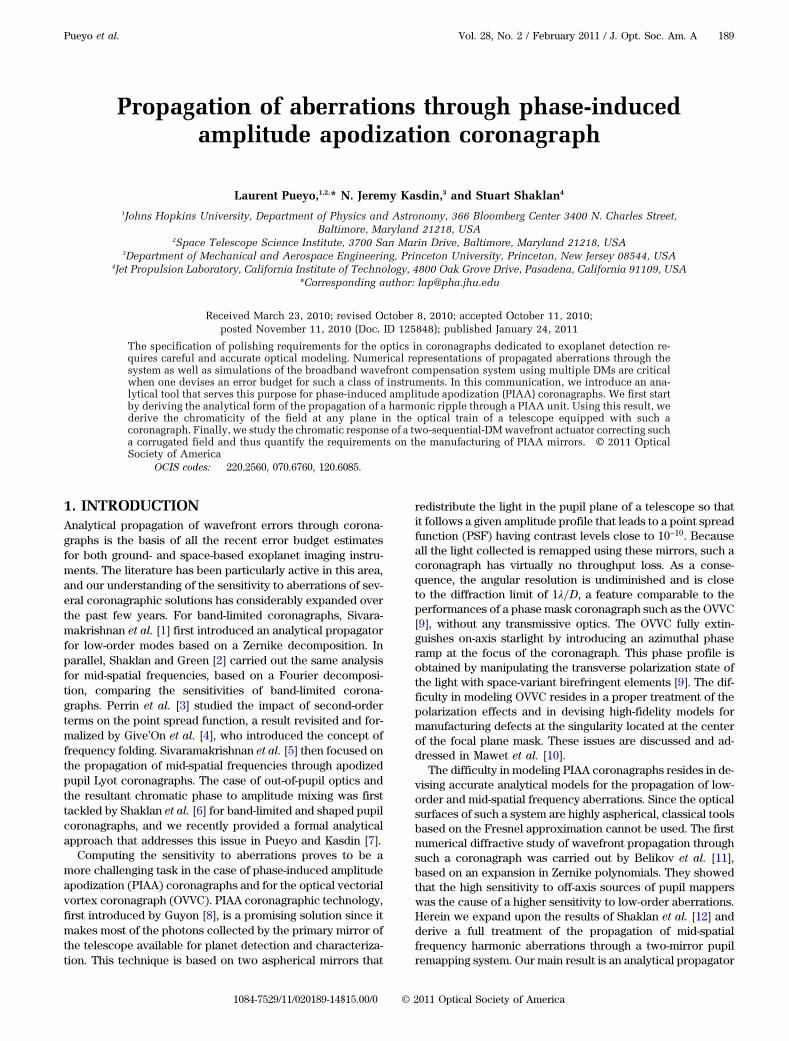
2. BACKGROUNDAs shown in Fig. 1, a pupil remapping unit is composed of twoaspherical mirrors that remap the light of an incoming pupilaccording to a prescribed apodization profile (Traub andVanderbei [13]). As presented in Guyon [8], a PIAA corona-graph is composed of two remapping units separated by a fo-cal plane mask. The first set of aspherical mirrors remaps thetelescope pupil so that the starlight is concentrated in the coreof a very high contrast PSF. The focal plane stop blocks thecore of this PSF and hence removes the bulk of the starlight,while preserving most of the photons from a potential compa-nion. The purpose of the second unit is to invert the remap-ping in order to restore the imaging properties of the wholeapparatus. The purpose of this paper is to investigate the phy-sics and propagation properties of a single two-mirror remap-ping unit, and thus we solely focus on the “forward”combination shown on Fig. 1. In a future communication,we plan to use the findings reported here to study the perfor-mances of a full four-mirror PIAA coronagraph. In this section,we review the design equations of a circularly symmetric pupil
remapper for which the designed apodization is independentof azimuth:
Að~x; ~yÞ ¼ Að~rÞ: ð1ÞHere ð~x; ~yÞ and ð~r; ~θÞ are the location of the rays at M2 in Car-tesian and polar coordinates, respectively. Similarly, ðx; yÞand ðr; θÞ are the location of rays at M1 in Cartesian and polarcoordinates, respectively. In the most general case, as shownin the bottom right panel of Fig. 1, the diffraction-limited fieldat a location at M2, ð~x; ~yÞ, is given by the sum of diffractedwavelets at each point at the surface of M1. In the particularcase of ray optics, there is no summation involved, and thereis only a 1 to 1 mapping between the field at ð~x; ~yÞ and the fieldat the incident point on M1ðx0ð~x; ~yÞ; y0ð~x; ~yÞÞ. For a givenð~x; ~yÞ, the coordinates ðx0ð~x; ~yÞ; y0ð~x; ~yÞÞ are derived from themirror surfaces using Fermat’s principle. ðr0ð~x; ~yÞ; θ0ð~x; ~yÞÞare the coordinates of the same point in a polar system. With-out loss of generality, we choose, for the remainder of thispaper, to focus on pupil-to-pupil on-axis PIAA systems thatare shown in the bottom two panels of Fig. 1. Moreover, ifwe choose θ0 ¼ ~θ, then, following the presentation of Trauband Vanderbei [13], the relationship between the locationof the incident and outgoing rays can be written:
∂r0∂ ~r
¼ ~rr0
Að~rÞ2; ð2Þ
where r0 is the radial location of the incident ray at M1. Thedesign of the mirror shapes is then driven by the followingcoupled partial differential equations:
∂h∂r
����r0
¼ ~rðr0Þ − r0Z
; ð3Þ
∂ ~h∂ ~r
����~r¼ ~r − r0ð~rÞ
Z; ð4Þ
where hðrÞ is the height of M1, hð~rÞ is the height of M2, and Zis the distance between the two mirrors. Equations (3) and (4)were derived using a ray optics approximation. Unfortunately,in order to predict the contrast of an actual PIAA, it is neces-sary to carry out a full diffraction analysis.
In particular, Vanderbei [14] showed that edge propagationeffects limit the contrast to 10−5 for a two-mirror PIAA coro-nagraph alone. Pluzhnik et al. [15] subsequently showed thatpreapodizers and postapodizers can mitigate these effects anda 10−10 contrast can be recovered with little loss in throughputand angular resolution. Recently, we developed a new, purelyanalytical approach to the diffraction problem [16]. This newmethod can be applied to quantify the impact of diffraction ofthe edge of the remapping optics on contrast; using it, we re-produced the results of Vanderbei [14], which established aset of preapodizers and postapodizers that allow 10−10 withan aberration-free PIAA (Pueyo et al. [17]). Here we do notdelve into such an analysis, which will be the object of a futuredetailed communication, and choose to focus on the analyti-cal modeling of wavefront propagation. We start from themain theoretical result of [16]. Namely, for any geometry,the diffraction-limited field at M2 is well approximated by thefollowing quadratic integral:
Fig. 1. (Color online) Setup of the problem and notations. (Top left)Three-dimensional representation of a pupil-to-pupil off-axis PIAAsystem. (Top right) Side view of the geometrical remapping in a pu-pil-to-pupil off-axis PIAA system. (Bottom left) Side view of the geo-metrical remapping in a pupil-to-pupil on-axis PIAA unit; this is theconfiguration that is studied in this communication. (Bottom right)Side view of all the rays contributing to the diffractive field at a pointof coordinates ð~x; ~yÞ at M2. The ray corresponding to the geometricalremapping, which has coordinates ðx0ð~x; ~yÞ; y0ð~x; ~yÞÞ in the inputplane, is highlighted.
190 J. Opt. Soc. Am. A / Vol. 28, No. 2 / February 2011 Pueyo et al.
where the ray optics remapping in Cartesian coordinates isgiven by
x0ð~x; ~yÞ ¼ r0ð~rÞ cosð~θÞ; ð6Þ
y0ð~x; ~yÞ ¼ r0ð~rÞ sinð~θÞ: ð7Þ
The integral in Eq. (5) is a sum over all the contributions ofeach point at the surface of M1, while ray optics only relies onthe field at ðx0; y0Þ. Moreover, we show in Appendix A that, forcircularly symmetric systems, the outgoing field is given by
Eoutð~r; ~θÞ ¼1iλZ
×ZM1
Einðr; θÞei πλZ
�r0ð~rÞ~rAð~rÞ2ðr cosðθ−~θÞ−r0ð~rÞÞ
2þ ~rr0ð~rÞ
ðr sinðθ−~θÞÞ2�rdrdθ:
ð8Þ
This result is the starting point for our analysis of the propa-gation of aberrations through PIAA systems.
3. DIFFRACTION ANALYSIS OF PIAAIn this section, we are interested in finding an analytical ex-pression for the outgoing field when Einðx; yÞ is composed ofharmonic ripples. While here we are considering the propaga-tion of errors through a PIAA unit that is circularly symmetric,we choose to describe the aberration in Cartesian coordi-nates. By choosing a basis set that is not orthogonal over acircle, we do not guarantee the unicity or the finite supportof any given wavefront expansion. However, this choice leadsus to analytical insights about the chromatic mixing that oc-curs when a wavefront is propagated through a PIAA unit.Thus, here we follow the presentation of [6], and we studythe propagation of harmonic ripples of the following form:
ei2πD ðNr cosðϕ−θÞÞ; ð9Þ
where N is the spatial frequency of the ripple and ϕ is its or-ientation. The propagation of such a complex disturbancethrough a circularly symmetric pupil mapping coronagraphis described by the following theorem.
Theorem 1. Consider a pupil mapping system with pre-
scribed apodization Að~rÞ, whose incident illumination is
harmonic:
Einðr; θÞ ¼ ei2πD ðNr cosðϕ−θÞÞ: ð10Þ
Then, assuming that the edge effects are mitigated according
to the methodology presented in Pluzhnik et al. [15], usingpreapodizers and postapodizers, the field distribution at
M2 is
Eout;N;ϕð~r; ~θÞ ¼ Að~rÞei2πDNr0ð~rÞ cosð~θ−ϕÞ
× e−iπλZN
2
D2
�~rAð~rÞ2r0 ð~rÞ
cos2ð~θ−ϕÞþ�
r0 ð~rÞ~r
�2
sin2ð~θ−ϕÞ�; ð11Þ
where Að~rÞ is the apodization profile that is induced by the
two remapping mirrors.
Equation (11) combines the geometrical and diffractivepropagation effects of pupil mapping systems for mid-spatialfrequencies aberrations. This theorem is derived using Eq. (8)with Ein ¼ ei
2πD ðmxþnyÞ, our purpose being to decompose any
incoming wavefront before the remapping mirrors into asum of Fourier harmonics and propagate them analytically.
Proof. We start with Eq. (8) and rewrite it into a form si-milar to the Fresnel integral. First, we express the harmonicripple in polar coordinates:
Eoutð~r; ~θÞ ¼1iλZ
ZR
0
Z2π
0ei
2πDNðr cos θ cosϕþr sin θ sinϕÞ
× ei πλZ
�r0
~rAð~rÞ2ðr cosðθ−~θÞ−r0Þ2þ ~r
r0ðr sinðθ−~θÞÞ2
�rdrdθ
¼ 1iλZ
ZM1
ei2πDN ½u cosð~θ−ϕÞþv sinð~θ−ϕÞ�
× ei πλZ
�r0
~rAð~rÞ2ðu−r0Þ2þ ~r
r0v2
�dudv; ð12Þ
where we have applied a series of coordinate rotations in or-der to write Eoutð~r; ~θÞ in a form convenient to complete thesquare in the integrand. We then extract all the terms thatdo not depend on ðu; vÞ out of the integral and completethe squares. This yields
Eoutð~r; ~θÞ ¼1iλZ ei
2πDNr0 cosð~θ−ϕÞe
−iπλzN2
D2
�cos2ð~θ−ϕÞ~rAð~rÞ2r0
þsin2ð~θ−ϕÞr0~r
�
×ZM1
ei πλZ
�r0
~rAð~rÞ2
�u−r0−λzN
D~rAð~rÞ2r0
cosð~θ−ϕÞ�
2
þ ~rr0
�v−λzN
Dr0~r sinð~θ−ϕÞ
�2�dudv:
ð13Þ
The first exponential factor corresponds to the ray opticsremapping of the ripple. The second exponential factor ac-counts for propagation-induced phase-to-amplitude conver-sion, and the integral captures the edge oscillation effectsdue to the propagation, in the sense presented by Pluzhniket al. [15]. The propagation integral can be rewritten:
1iλZ
ZM1
ei πλZ
�r0
~rAð~rÞ2
�u−r0−
λzND
~rAð~rÞ2r0
cosð~θ−ϕÞ�
2
þ ~rr0
�v−λzN
Dr0~r sinð~θ−ϕÞ
�2�dudv
¼ Að~rÞZEλ;~r;~θ
eiρ2ρdρdψ ; ð14Þ
where Eλ;~r;~θ is an ellipse centered at ðλzND ~rAð~rÞ2r0
cosð~θ −ϕÞ; λzND r0
~r sinð~θ − ϕÞÞ of semi-major axis aE ¼ ð πλZ
r0~rAð~rÞ2Þ−1 and
semi-minor axis bE ¼ ð πλZ
~rr0Þ−1. When the phase oscillations
at M2 have been mitigated using preapodizers and postapodi-zers, along the lines of Pluzhnkik et al. [15], the diffractiveproperties are equivalent to a ray optics propagation, namelyaE → ∞ and bE → ∞:
Pueyo et al. Vol. 28, No. 2 / February 2011 / J. Opt. Soc. Am. A 191
1iλZ
ZM1
ei πλZ
�r0
~rAð~rÞ2ðu−r0Þ2þ ~r
r0v2
�dudv≃ Að~rÞ: ð15Þ
This finishes our proof.In the remainder of the paper, we use Theorem 1 to com-
pute the effects of propagated harmonic aberrations on thefinal image and to determine limits on the wavefront con-trol system. Another application of Eq. (11) is presented inAppendix B, where we evaluate the sensitivity of PIAA sys-tems to off-axis sources.
4. PROPAGATION OF HARMONICABERRATIONSIn a previous paper [7], we illustrated the impact of out-of-pupil plane optics on the final aberrated field in regular cor-onographs. These are responsible for mixing the amplitude/phase nature of aberrations and for changing their chromaticbehavior. We showed that these effects could be mitigatedusing a two-sequential-DM wavefront controller. The sameproblem arises for PIAA coronagraphs, since it is intrinsicallycomposed of two surfaces that are not only out of conjugacywith respect to the telescope pupil, but that also are highlynonparabolic, thus introducing extra perturbations on thewavefront. In this section, we show how to use the propagatorderived in Eq. (11) to quantify the chromaticity of post-PIAAaberrated wavefronts.
A. Phase to Amplitude ConversionWe first consider the case of a phase error in the field rightafter M1 that is given by Einðx; yÞ ¼ ei
2πλ hðh;yÞ. Note that this
phase error can either stem from optics before PIAA M1 oron the surface of M1:
hðx; yÞ ¼Xm;n
λ0bm;nei2πD ðmxþnyÞ; ð16Þ
¼Xm;n
λ0bm;nei2πD
ffiffiffiffiffiffiffiffiffiffiffim2þn2
pðx cos θn;mþy sin θm;nÞ; ð17Þ
where θm;n ¼ tan−1ðnmÞ, λ0 is the central wavelength andb−m;−n ¼ b�m;n are nondimensional Fourier coefficients. We as-sume for now that the bm;n coefficients are small enough thatthe field at M1 can be approximated by
ei2πλ h ≃
�1þ i
2πλ h
�: ð18Þ
Note that, under this linear approximation, a phase error isequivalent to an imaginary disturbance of the pupil plane,and an amplitude error is equivalent to a real disturbance. As-suming a circularly symmetric PIAA, Eq. (8) yields
Eoutð~r; ~θÞ ¼1iλZ
ZM1
�1þ i
2πλ hðx; yÞ
�
× ei πλZ
�r0
~rAð~rÞ2ðr cosðθ−~θÞ−r0Þ2þ ~r
r0ðr sinðθ−~θÞÞ2
�rdrdθ: ð19Þ
Therefore, using the Fourier expansion of hðx; yÞ in Eq. (17)and Theorem 1,
Eoutð~r; ~θÞ ¼ Að~rÞ0@1þ 2πλ0
λ
×Xm;n
bm;nei2πD
ffiffiffiffiffiffiffiffiffiffiffim2þn2
pðr0 cos ~θ cos θm;nþr0 sin ~θ sin θm;nÞ
× e−iπλZðm
2þn2 ÞD2
��~rAð~rÞr0
�2
cos2ð~θ−θm;nÞþ�
r0~r
�2
sin2ð~θ−θm;nÞ�1CA:
ð20Þ
The general form for the propagator of phase errors in clas-sical coronagraph behaves, as derived in Pueyo and Kasdin
[7], as e−iπλzN2
D2 . The propagator derived here does feature thesame behavior but also captures the high curvature of thePIAA optics through the angular magnification factorð~rAð~rÞr0
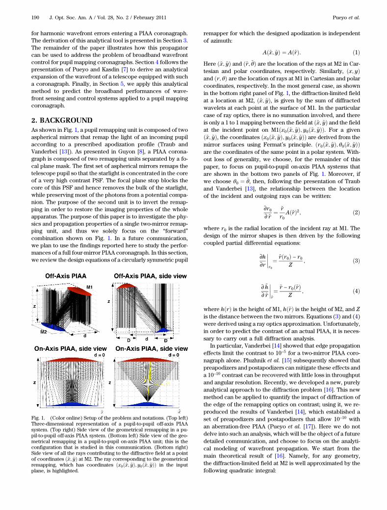
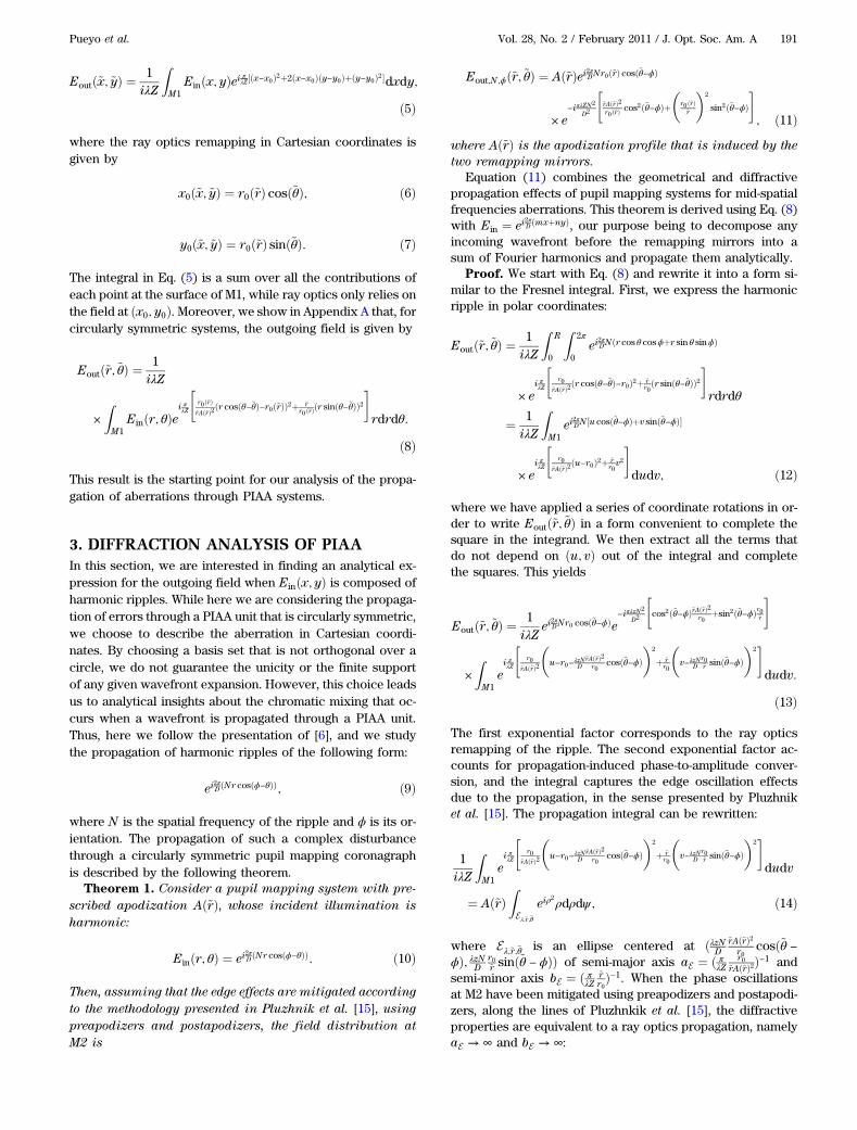
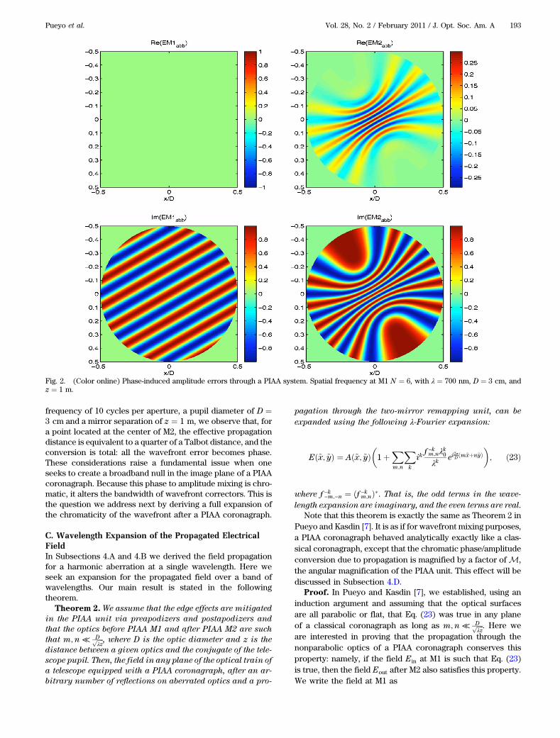
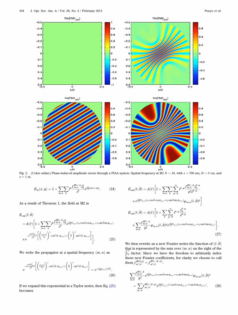
Þ2 cos2ð~θ − θm;nÞ þ ðr0~r Þ2 sin2ð~θ − θm;nÞ. This magnificationis different in the radial and tangential directions. Therefore,in the angular spectrum factor, the contribution of the radialmagnification is weighted by the relative orientation of the rip-ple, θm;n, with respect to the line of observation, ~θ. This yieldsa term in cos2ð~θ − θm;nÞ. The same consideration for the tan-gential direction yields a term in sin2ð~θ − θm;nÞ2. Seen fromM2,it is as if the ripples at M1 were propagating along two ortho-gonal pupil mappers of different linear magnification laws. Asa consequence, a phase ripple at M1 will not only appear at M2as a condensed oscillatory pattern, as predicted by the laws ofgeometric optics, but will also see some of its energy trans-ferred to amplitude, thus creating phase-induced amplitudeerrors. This effect gets stronger with spatial frequency as illu-strated in Figs. 2 and 3. In Fig. 3, computed at λ ¼ 700 nm, fora spatial frequency of 10 cycles per aperture, a pupil diameterof D ¼ 3 cm, and a mirror separation of z ¼ 1 m, the effectivepropagation distance is equivalent to a quarter of a Talbotdistance, and the conversion is total: all the wavefront errorbecomes amplitude. This phase-to-amplitude conversion be-haves as D2=λz, the Fresnel number of the PIAA unit. Thusthis design parameter has a direct impact on the feasibilityof broadband wavefront control.
B. Amplitude-Induced Phase ErrorThe same approach can be carried out starting with amplitudeerrors in the field right after M1:
Einðx; yÞ ¼ r0
�1þ
Xm;n
am;nei2πD ðmxþnyÞ
�; ð21Þ
where a−m;−n ¼ a�m;n are non dimensional coefficients, and r0is the average transmissivity of the incident field. This leads tothe derivation of amplitude-induced phase errors that is givenby
Eoutð~r;~θÞ¼Að~rÞ0@1þ
Xm;n
am;nei2πD
ffiffiffiffiffiffiffiffiffiffiffim2þn2
pðr0 cos~θcosθm;nþr0 sin~θsinθm;nÞ
×e−iπλZðm
2þn2ÞD2
��~rAð~rÞr0
�2
cos2ð~θ−θm;nÞþ�
r0~r
�2
sin2ð~θ−θm;nÞ�1CA: ð22Þ
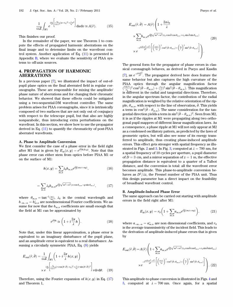
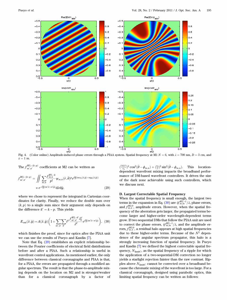
This amplitude-to-phase conversion is illustrated in Figs. 4 and5, computed at λ ¼ 700 nm. Once again, for a spatial
192 J. Opt. Soc. Am. A / Vol. 28, No. 2 / February 2011 Pueyo et al.
frequency of 10 cycles per aperture, a pupil diameter of D ¼3 cm and a mirror separation of z ¼ 1 m, we observe that, fora point located at the center of M2, the effective propagationdistance is equivalent to a quarter of a Talbot distance, and theconversion is total: all the wavefront error becomes phase.These considerations raise a fundamental issue when oneseeks to create a broadband null in the image plane of a PIAAcoronagraph. Because this phase to amplitude mixing is chro-matic, it alters the bandwidth of wavefront correctors. This isthe question we address next by deriving a full expansion ofthe chromaticity of the wavefront after a PIAA coronagraph.
C. Wavelength Expansion of the Propagated ElectricalFieldIn Subsections 4.A and 4.B we derived the field propagationfor a harmonic aberration at a single wavelength. Here weseek an expansion for the propagated field over a band ofwavelengths. Our main result is stated in the followingtheorem.
Theorem 2. We assume that the edge effects are mitigated
in the PIAA unit via preapodizers and postapodizers and
that the optics before PIAA M1 and after PIAA M2 are such
that m;n ≪Dffiffiffiffiλz
p , where D is the optic diameter and z is the
distance between a given optics and the conjugate of the tele-
scope pupil. Then, the field in any plane of the optical train of
a telescope equipped with a PIAA coronagraph, after an ar-
bitrary number of reflections on aberrated optics and a pro-
pagation through the two-mirror remapping unit, can be
expanded using the following λ-Fourier expansion:
Eð~x; ~yÞ ¼ Að~x; ~yÞ�1þ
Xm;n
Xk
ikf −km;nλk0λk ei
2πDðm~xþn~yÞ
�; ð23Þ
where f −k−m;−n ¼ ðf −km;nÞ�. That is, the odd terms in the wave-
length expansion are imaginary, and the even terms are real.Note that this theorem is exactly the same as Theorem 2 in
Pueyo and Kasdin [7]. It is as if for wavefront mixing purposes,a PIAA coronagraph behaved analytically exactly like a clas-sical coronagraph, except that the chromatic phase/amplitudeconversion due to propagation is magnified by a factor of M,the angular magnification of the PIAA unit. This effect will bediscussed in Subsection 4.D.
Proof. In Pueyo and Kasdin [7], we established, using aninduction argument and assuming that the optical surfacesare all parabolic or flat, that Eq. (23) was true in any planeof a classical coronagraph as long as m;n ≪
Dffiffiffiffiλz
p . Here weare interested in proving that the propagation through thenonparabolic optics of a PIAA coronagraph conserves thisproperty: namely, if the field Ein at M1 is such that Eq. (23)is true, then the field Eout after M2 also satisfies this property.We write the field at M1 as
Fig. 2. (Color online) Phase-induced amplitude errors through a PIAA system. Spatial frequency at M1 N ¼ 6, with λ ¼ 700 nm, D ¼ 3 cm, andz ¼ 1 m.
Pueyo et al. Vol. 28, No. 2 / February 2011 / J. Opt. Soc. Am. A 193
Einðx; yÞ ¼ 1þXm;n
Xk
ikf M1;−km;n λk0λk ei
2πD ðmxþnyÞ: ð24Þ
As a result of Theorem 1, the field at M2 is
Eoutð~r;~θÞ
¼Að~rÞ�1þ
Xm;n
Xk
ikf M1;−km;n λk0λk ei
2πDNm;nðr0 cos~θcosϕm;nþr0 sin~θ sinϕm;nÞ
× e−i
πλZN2m;n
D2
��~rAð~rÞ2r0
�2
cos2ð~θ−ϕm;nÞþ�
r0~r
�2
sin2ð~θ−ϕm;nÞ��
: ð25Þ
We write the propagator at a spatial frequency ðm;nÞ as
e−i
πλZN2m;n
D2
��~rAð~rÞ2r0
�2
cos2ð~θ−ϕm;nÞþ�
r0~r
�2
sin2ð~θ−ϕm;nÞ�¼ e−i
λλ0ψm;nð~r;~θÞ:
ð26Þ
If we expand this exponential in a Taylor series, then Eq. (25)becomes
Eoutð~r; ~θÞ ¼ Að~rÞ�1þ
Xm;n
Xk
X∞p¼0
ik−pf M1;−km;n λk−p0
p!λk−p
× ei2πDNm;nðr0 cos ~θ cosϕm;nþr0 sin ~θ sinϕm;nÞψm;nð~r; ~θÞp
�
Eoutð~r; ~θÞ ¼ Að~rÞ�1þ
Xk
X∞p¼0
ik−pλk−p0
λk−p
×Xm;n
f M1;−km;n
p!ψm;nð~r; ~θÞpei2πDNm;nðr0 cos ~θ cosϕm;nþr0 sin ~θ sinϕm;nÞ
�:
ð27Þ
We then rewrite as a new Fourier series the function of ð~r; ~θÞthat is represented by the sum over ðm;nÞ on the right of theλk−p0
λk−p factor. Since we have the freedom to arbitrarily indexthese new Fourier coefficients, for clarity we choose to callthem f M2;k;p
m0 ;n0 ¼ f M2;−ðk−pÞm0 ;n0 :
Xm;n
f M1;−km;n
p!ei
2πDNm;nðr0 cos ~θ cosϕm;nþr0 sin ~θ sinϕm;nÞψm;mð~r; ~θÞp
¼Xm0;n0
f M2;−ðk−pÞm0;n0 ei
2πDNm0 ;n0 ð~r cos ~θ cosϕm0 ;n0 þ~r sin ~θ sinϕm0 ;n0 Þ: ð28Þ
Fig. 3. (Color online) Phase-induced amplitude errors through a PIAA system. Spatial frequency at M1 N ¼ 10, with λ ¼ 700 nm, D ¼ 3 cm, andz ¼ 1 m.
194 J. Opt. Soc. Am. A / Vol. 28, No. 2 / February 2011 Pueyo et al.
The f M2;−ðk−pÞm0;n0 coefficients at M2 can be written as
f M2;−ðk−pÞm0 ;n0 ¼
ZZ Xm;n
f M1;−km;n
p!ψm;nð~r; ~θÞpei2πD ðmx0ð~x;~yÞþny0ð~x;~yÞÞ
× e−i2πD ðm0~xþn0~yÞd~xd~y; ð29Þ
where we chose to represent the integrand in Cartesian coor-dinates for clarity. Finally, we reduce the double sum overðk; pÞ to a single sum since their argument only depends onthe difference k0 ¼ k − p. This yields
Eoutð~x;~yÞ¼Að~x;~yÞ�1þ
Xm0;n0
Xk0ik
0 fM2;−k0m0;n0 λk00λk0
ei2πD ðm0~xþn0~yÞ
�; ð30Þ
which finishes the proof, since for optics after the PIAA unitwe can use the results of Pueyo and Kasdin [7].
Note that Eq. (29) establishes an explicit relationship be-tween the Fourier coefficients of electrical field distributionsbefore and after a PIAA. Such a relationship is useful inwavefront control applications. As mentioned earlier, the onlydifference between classical coronagraphs and PIAA is that,for a PIAA, the errors are propagated through a modified an-gular spectrum. The result is that the phase-to-amplitude mix-ing depends on the location on M2 and is stronger/weakerthan for a classical coronagraph by a factor of
dependent wavefront mixing impacts the broadband perfor-mance of DM-based wavefront controllers. It drives the sizeof the dark zone achievable using such controllers, whichwe discuss next.
D. Largest Correctable Spatial FrequencyWhen the spatial frequency is small enough, the largest twoterms in the expansion in Eq. (30) are if M2;−1
m;m =λ, phase errors,and f M2;0
m;n , amplitude errors. However, when the spatial fre-quency of the aberration gets larger, the propagated terms be-come larger and higher-order wavelength-dependent termsgrow. If two sequential DMs that follow the PIAA unit are usedto correct the phase errors, if M2;−1
m;m =λ, and the amplitude er-rors, f M2;0
m;n , a residual halo appears at high spatial frequenciesdue to these higher-order terms. Because of the N2 depen-dence of the angular spectrum propagator, this halo is astrongly increasing function of spatial frequency. In Pueyoand Kasdin [7] we defined the highest correctable spatial fre-quency, N limitC , as the spatial frequency of a ripple for whichthe application of a two-sequential-DM correction no longeryields a starlight rejection fainter than the raw contrast. Rip-ples above N limitC cannot be corrected over a broadband be-cause the chromatic mixing of the wavefront is too large. For aclassical coronagraph, designed using parabolic optics, thislimiting spatial frequency can be written as follows:
Fig. 4. (Color online) Amplitude-induced phase errors through a PIAA system. Spatial frequency at M1 N ¼ 6, with λ ¼ 700 nm, D ¼ 3 cm, andz ¼ 1 m.
Pueyo et al. Vol. 28, No. 2 / February 2011 / J. Opt. Soc. Am. A 195
N limitC ¼ Dffiffiffiffiffiffiffiλ0z
p� λ0Δλ
�1=2
: ð31Þ
The same considerations are valid for a PIAA coronagraph.However, when the DMs are located after the remappingmirrors, then the average spatial frequency seen by the pro-pagator is increased by a factor of M, as shown in Eq. (29)where the Fourier kernel is now written as a function ofðx0ð~x; ~yÞ; y0ð~x; ~yÞÞ. Thus, if the maximal correctable spatialfrequency is expressed in terms of cycles per aperture beforethe PIAA, then N limitPIAA becomes
N limitPIAA ¼ DM
ffiffiffiffiffiffiffiλ0z
p� λ0Δλ
�1=2
: ð32Þ
While the final wavefront expansion is similar for PIAA andclassical coronagraphs, the higher-order propagation termsare larger for PIAA, thus reducing the largest spatial frequencycorrectable under a broadband illumination. With DMs lo-cated before the PIAA unit, the largest correctable spatialfrequency would be driven by the surface errors at M2,back-propagated to the plane of M1. We will study this con-figuration in a future communication. Here we emphasize thata two-sequential-DM wavefront controller that follows a PIAAunit will not be able to correct spatial frequencies above
N limitPIAA, expressed in Eq. (32), over a broadband, due to aphase to amplitude mixing that is too strong.
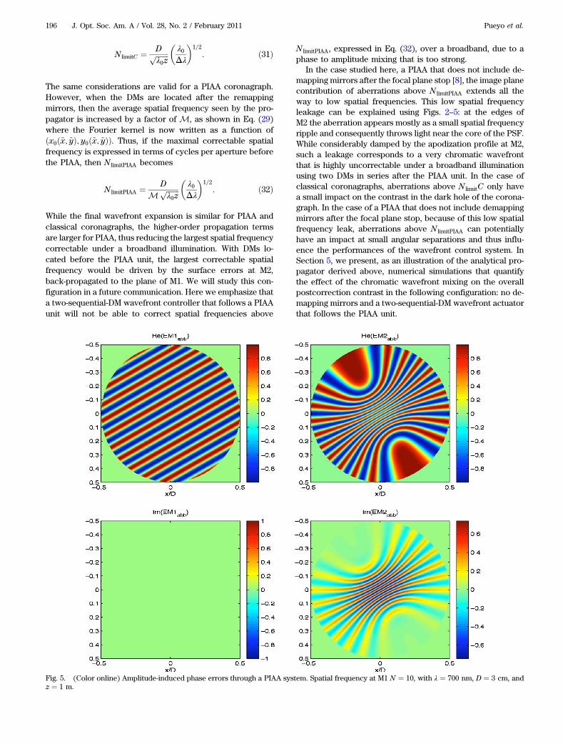
In the case studied here, a PIAA that does not include de-mapping mirrors after the focal plane stop [8], the image planecontribution of aberrations above N limitPIAA extends all theway to low spatial frequencies. This low spatial frequencyleakage can be explained using Figs. 2–5: at the edges ofM2 the aberration appears mostly as a small spatial frequencyripple and consequently throws light near the core of the PSF.While considerably damped by the apodization profile at M2,such a leakage corresponds to a very chromatic wavefrontthat is highly uncorrectable under a broadband illuminationusing two DMs in series after the PIAA unit. In the case ofclassical coronagraphs, aberrations above N limitC only havea small impact on the contrast in the dark hole of the corona-graph. In the case of a PIAA that does not include demappingmirrors after the focal plane stop, because of this low spatialfrequency leak, aberrations above N limitPIAA can potentiallyhave an impact at small angular separations and thus influ-ence the performances of the wavefront control system. InSection 5, we present, as an illustration of the analytical pro-pagator derived above, numerical simulations that quantifythe effect of the chromatic wavefront mixing on the overallpostcorrection contrast in the following configuration: no de-mapping mirrors and a two-sequential-DM wavefront actuatorthat follows the PIAA unit.
Fig. 5. (Color online) Amplitude-induced phase errors through a PIAA system. Spatial frequency at M1 N ¼ 10, with λ ¼ 700 nm, D ¼ 3 cm, andz ¼ 1 m.
196 J. Opt. Soc. Am. A / Vol. 28, No. 2 / February 2011 Pueyo et al.
5. CONTRAST PREDICTIONSWe use the analytical expansion in Eq. (23) to predict the bestbroadband contrast that can be achieved by a PIAA unit in thepresence of fixed wavefront errors compensated by a pair ofsequential DMs located after the remapping mirrors. Note thatdifferent, and potentially better, broadband performances canbe obtained with DMs located before the remapping mirrorsor a demapping unit after the focal plane mask. While thesearchitectures can be studied using the approach presentedhere, their implementation requires novel wavefront controlalgorithms that are beyond the scope of this paper. Thus,we decided here to focus on quantifying the limitations ofthe simplest solution possible. We will extend this study toall possible combinations of DM before/after the PIAA mirrorsand with/without a demapper in a future communication.
Because the propagator is wavelength-dependent, thewavelength expansion of the field at M2 exhibits an infinitenumber of terms, whereas, as shown by Shaklan and Green[18], two sequential DMs can only correct for the λ0 andi1=λ terms. In this section, we isolate one Fourier component,at a given spatial frequency, and quantify how well a two-sequential-DM wavefront controller can reject it under abroadband illumination.
A. MethodologyFor a given phase error at M1, and a bandwidth centeredaround λ0, we use a first-order expansion of the wavefront
Ein ¼ 1þ iλ0λ ei
2πD ðmxþnyÞ: ð33Þ
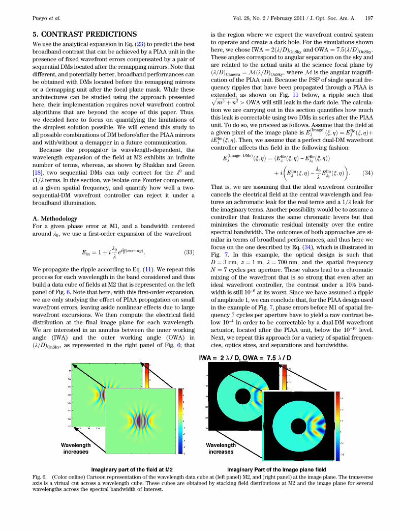
We propagate the ripple according to Eq. (11). We repeat thisprocess for each wavelength in the band considered and thusbuild a data cube of fields at M2 that is represented on the leftpanel of Fig. 6. Note that here, with this first-order expansion,we are only studying the effect of PIAA propagation on smallwavefront errors, leaving aside nonlinear effects due to largewavefront excursions. We then compute the electrical fielddistribution at the final image plane for each wavelength.We are interested in an annulus between the inner workingangle (IWA) and the outer working angle (OWA) inðλ=DÞOnSky, as represented in the right panel of Fig. 6; that
is the region where we expect the wavefront control systemto operate and create a dark hole. For the simulations shownhere, we chose IWA ¼ 2ðλ=DÞOnSky and OWA ¼ 7:5ðλ=DÞOnSky.These angles correspond to angular separation on the sky andare related to the actual units at the science focal plane byðλ=DÞCamera ¼ Mðλ=DÞOnSky, where M is the angular magnifi-cation of the PIAA unit. Because the PSF of single spatial fre-quency ripples that have been propagated through a PIAA isextended, as shown on Fig. 11 below, a ripple such thatffiffiffiffiffiffiffiffiffiffiffiffiffiffiffiffiffi
m2 þ n2p
> OWA will still leak in the dark dole. The calcula-tion we are carrying out in this section quantifies how muchthis leak is correctable using two DMs in series after the PIAAunit. To do so, we proceed as follows. Assume that the field ata given pixel of the image plane is EðImageÞ
λ ðξ; ηÞ ¼ EReλ ðξ; ηÞþ
iEImλ ðξ; ηÞ. Then, we assume that a perfect dual-DM wavefront
controller affects this field in the following fashion:
EðImage−DMsÞλ ðξ; ηÞ ¼ ðERe
λ ðξ; ηÞ − EReλ0 ðξ; ηÞÞ
þ i
�EImλ ðξ; ηÞ − λ0
λ EImλ0 ðξ; ηÞ
�: ð34Þ
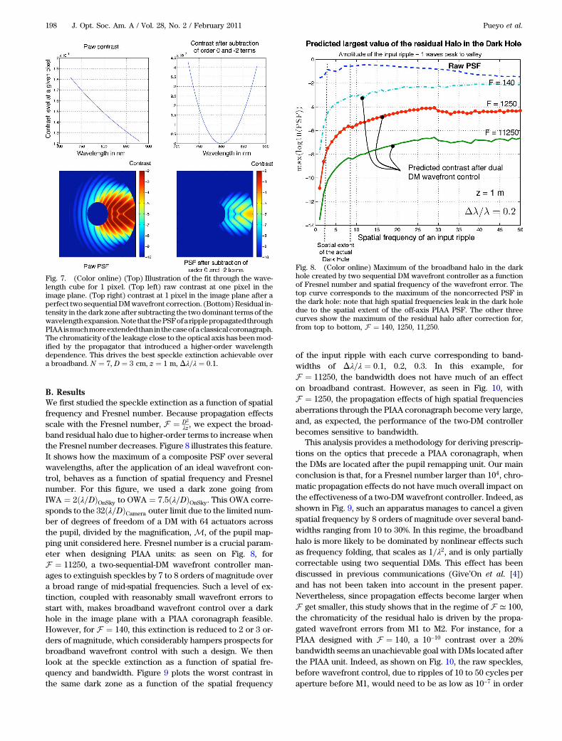
That is, we are assuming that the ideal wavefront controllercancels the electrical field at the central wavelength and fea-tures an achromatic leak for the real terms and a 1=λ leak forthe imaginary terms. Another possibility would be to assume acontroller that features the same chromatic levers but thatminimizes the chromatic residual intensity over the entirespectral bandwidth. The outcomes of both approaches are si-milar in terms of broadband performances, and thus here wefocus on the one described by Eq. (34), which is illustrated inFig. 7. In this example, the optical design is such thatD ¼ 3 cm, z ¼ 1 m, λ ¼ 700 nm, and the spatial frequencyN ¼ 7 cycles per aperture. These values lead to a chromaticmixing of the wavefront that is so strong that even after anideal wavefront controller, the contrast under a 10% band-width is still 10−6 at its worst. Since we have assumed a rippleof amplitude 1, we can conclude that, for the PIAA design usedin the example of Fig. 7, phase errors before M1 of spatial fre-quency 7 cycles per aperture have to yield a raw contrast be-low 10−4 in order to be correctable by a dual-DM wavefrontactuator, located after the PIAA unit, below the 10−10 level.Next, we repeat this approach for a variety of spatial frequen-cies, optics sizes, and separations and bandwidths.
Fig. 6. (Color online) Cartoon representation of the wavelength data cube at (left panel) M2, and (right panel) at the image plane. The transverseaxis is a virtual cut across a wavelength cube. These cubes are obtained by stacking field distributions at M2 and the image plane for severalwavelengths across the spectral bandwidth of interest.
Pueyo et al. Vol. 28, No. 2 / February 2011 / J. Opt. Soc. Am. A 197
B. ResultsWe first studied the speckle extinction as a function of spatialfrequency and Fresnel number. Because propagation effectsscale with the Fresnel number, F ¼ D2
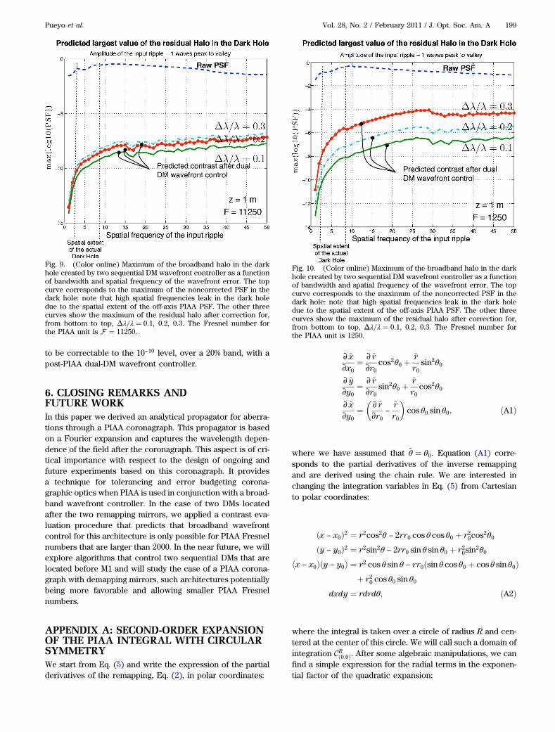
λz, we expect the broad-band residual halo due to higher-order terms to increase whenthe Fresnel number decreases. Figure 8 illustrates this feature.It shows how the maximum of a composite PSF over severalwavelengths, after the application of an ideal wavefront con-trol, behaves as a function of spatial frequency and Fresnelnumber. For this figure, we used a dark zone going fromIWA ¼ 2ðλ=DÞOnSky to OWA ¼ 7:5ðλ=DÞOnSky. This OWA corre-sponds to the 32ðλ=DÞCamera outer limit due to the limited num-ber of degrees of freedom of a DM with 64 actuators acrossthe pupil, divided by the magnification, M, of the pupil map-ping unit considered here. Fresnel number is a crucial param-eter when designing PIAA units: as seen on Fig. 8, forF ¼ 11250, a two-sequential-DM wavefront controller man-ages to extinguish speckles by 7 to 8 orders of magnitude overa broad range of mid-spatial frequencies. Such a level of ex-tinction, coupled with reasonably small wavefront errors tostart with, makes broadband wavefront control over a darkhole in the image plane with a PIAA coronagraph feasible.However, for F ¼ 140, this extinction is reduced to 2 or 3 or-ders of magnitude, which considerably hampers prospects forbroadband wavefront control with such a design. We thenlook at the speckle extinction as a function of spatial fre-quency and bandwidth. Figure 9 plots the worst contrast inthe same dark zone as a function of the spatial frequency
of the input ripple with each curve corresponding to band-widths of Δλ=λ ¼ 0:1, 0.2, 0.3. In this example, forF ¼ 11250, the bandwidth does not have much of an effecton broadband contrast. However, as seen in Fig. 10, withF ¼ 1250, the propagation effects of high spatial frequenciesaberrations through the PIAA coronagraph become very large,and, as expected, the performance of the two-DM controllerbecomes sensitive to bandwidth.
This analysis provides a methodology for deriving prescrip-tions on the optics that precede a PIAA coronagraph, whenthe DMs are located after the pupil remapping unit. Our mainconclusion is that, for a Fresnel number larger than 104, chro-matic propagation effects do not have much overall impact onthe effectiveness of a two-DMwavefront controller. Indeed, asshown in Fig. 9, such an apparatus manages to cancel a givenspatial frequency by 8 orders of magnitude over several band-widths ranging from 10 to 30%. In this regime, the broadbandhalo is more likely to be dominated by nonlinear effects suchas frequency folding, that scales as 1=λ2, and is only partiallycorrectable using two sequential DMs. This effect has beendiscussed in previous communications (Give’On et al. [4])and has not been taken into account in the present paper.Nevertheless, since propagation effects become larger whenF get smaller, this study shows that in the regime of F ≃ 100,the chromaticity of the residual halo is driven by the propa-gated wavefront errors from M1 to M2. For instance, for aPIAA designed with F ¼ 140, a 10−10 contrast over a 20%bandwidth seems an unachievable goal with DMs located afterthe PIAA unit. Indeed, as shown on Fig. 10, the raw speckles,before wavefront control, due to ripples of 10 to 50 cycles peraperture before M1, would need to be as low as 10−7 in order
Fig. 8. (Color online) Maximum of the broadband halo in the darkhole created by two sequential DM wavefront controller as a functionof Fresnel number and spatial frequency of the wavefront error. Thetop curve corresponds to the maximum of the noncorrected PSF inthe dark hole: note that high spatial frequencies leak in the dark holedue to the spatial extent of the off-axis PIAA PSF. The other threecurves show the maximum of the residual halo after correction for,from top to bottom, F ¼ 140, 1250, 11,250.
Fig. 7. (Color online) (Top) Illustration of the fit through the wave-length cube for 1 pixel. (Top left) raw contrast at one pixel in theimage plane. (Top right) contrast at 1 pixel in the image plane after aperfect two sequential DMwavefront correction. (Bottom)Residual in-tensity in the dark zone after subtracting the two dominant terms of thewavelengthexpansion.Note that thePSFofaripplepropagatedthroughPIAAismuchmoreextendedthan in thecaseofaclassicalcoronagraph.The chromaticity of the leakage close to the optical axis has beenmod-ified by the propagator that introduced a higher-order wavelengthdependence. This drives the best speckle extinction achievable overa broadband. N ¼ 7, D ¼ 3 cm, z ¼ 1 m,Δλ=λ ¼ 0:1.
198 J. Opt. Soc. Am. A / Vol. 28, No. 2 / February 2011 Pueyo et al.
to be correctable to the 10−10 level, over a 20% band, with apost-PIAA dual-DM wavefront controller.
6. CLOSING REMARKS ANDFUTURE WORKIn this paper we derived an analytical propagator for aberra-tions through a PIAA coronagraph. This propagator is basedon a Fourier expansion and captures the wavelength depen-dence of the field after the coronagraph. This aspect is of cri-tical importance with respect to the design of ongoing andfuture experiments based on this coronagraph. It providesa technique for tolerancing and error budgeting corona-graphic optics when PIAA is used in conjunction with a broad-band wavefront controller. In the case of two DMs locatedafter the two remapping mirrors, we applied a contrast eva-luation procedure that predicts that broadband wavefrontcontrol for this architecture is only possible for PIAA Fresnelnumbers that are larger than 2000. In the near future, we willexplore algorithms that control two sequential DMs that arelocated before M1 and will study the case of a PIAA corona-graph with demapping mirrors, such architectures potentiallybeing more favorable and allowing smaller PIAA Fresnelnumbers.
APPENDIX A: SECOND-ORDER EXPANSIONOF THE PIAA INTEGRAL WITH CIRCULARSYMMETRYWe start from Eq. (5) and write the expression of the partialderivatives of the remapping, Eq. (2), in polar coordinates:
∂ ~x∂x0
¼ ∂ ~r∂r0
cos2θ0 þ~rr0
sin2θ0
∂ ~y∂y0
¼ ∂ ~r∂r0
sin2θ0 þ~rr0
cos2θ0
∂ ~x∂y0
¼�∂ ~r∂r0
−~rr0
�cos θ0 sin θ0; ðA1Þ
where we have assumed that ~θ ¼ θ0. Equation (A1) corre-sponds to the partial derivatives of the inverse remappingand are derived using the chain rule. We are interested inchanging the integration variables in Eq. (5) from Cartesianto polar coordinates:
ðx − x0Þ2 ¼ r2cos2θ − 2rr0 cos θ cos θ0 þ r20cos2θ0
ðy − y0Þ2 ¼ r2sin2θ − 2rr0 sin θ sin θ0 þ r20sin2θ0
ðx − x0Þðy − y0Þ ¼ r2 cos θ sin θ − rr0ðsin θ cos θ0 þ cos θ sin θ0Þþ r20 cos θ0 sin θ0
dxdy ¼ rdrdθ; ðA2Þ
where the integral is taken over a circle of radius R and cen-tered at the center of this circle. We will call such a domain ofintegration CRð0;0Þ. After some algebraic manipulations, we canfind a simple expression for the radial terms in the exponen-tial factor of the quadratic expansion:
Fig. 9. (Color online) Maximum of the broadband halo in the darkhole created by two sequential DM wavefront controller as a functionof bandwidth and spatial frequency of the wavefront error. The topcurve corresponds to the maximum of the noncorrected PSF in thedark hole: note that high spatial frequencies leak in the dark holedue to the spatial extent of the off-axis PIAA PSF. The other threecurves show the maximum of the residual halo after correction for,from bottom to top, Δλ=λ ¼ 0:1, 0.2, 0.3. The Fresnel number forthe PIAA unit is F ¼ 11250.
Fig. 10. (Color online) Maximum of the broadband halo in the darkhole created by two sequential DM wavefront controller as a functionof bandwidth and spatial frequency of the wavefront error. The topcurve corresponds to the maximum of the noncorrected PSF in thedark hole: note that high spatial frequencies leak in the dark holedue to the spatial extent of the off-axis PIAA PSF. The other threecurves show the maximum of the residual halo after correction for,from bottom to top, Δλ=λ ¼ 0:1, 0.2, 0.3. The Fresnel number forthe PIAA unit is 1250.
Pueyo et al. Vol. 28, No. 2 / February 2011 / J. Opt. Soc. Am. A 199
r2∶d ~rdr0
cos2ðθ − θ0Þ þ~rr0
sin2ðθ − θ0Þ
r20∶d ~rdr0
rr0∶2d ~rdr0
cosðθ − θ0Þ: ðA3Þ
As a consequence, the radial field distribution after M2becomes:
Eoutð~rÞ ¼1iλZ
ZCRð0;0Þ
ei πλZ
�r0
~rAð~rÞ2ðr cos θ−r0Þ2þ ~r
r0ðr sin θÞ2
�rdrdθ; ðA4Þ
Eoutð~rÞ ¼1iλZ
ZCRð0;0Þ
ei πλZ
�r0
~rAð~rÞ2ðx−r0Þ2þ ~r
r0y2
�dxdy: ðA5Þ
The main insight of this expansion is that the propagation be-tween the two mirrors of such a PIAA system reduces to the
integration over an equivalent elliptical aperture. The geome-try of this ellipse varies with ~r, the location on M2. Qualita-tively, based on an energy conservation argument, wealready know that the local effective aperture size for propa-gation purposes is stretched by a factor of ~rAð~rÞ2
r0in the radial
direction. The elliptical integral in Eq. (8) formally illustratesthis intuitive result, which states that since the area of integra-tion has to be Að~rÞ2, the effective local aperture size in thetangential direction, normal to the radial, has to shrink by afactor of r0
~r .
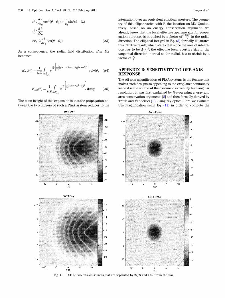
APPENDIX B: SENSITIVITY TO OFF-AXISRESPONSEThe off-axis magnification of PIAA systems is the feature thatmakes such designs so appealing to the exoplanet communitysince it is the source of their intrinsic extremely high angularresolution. It was first explained by Guyon using energy andarea conservation arguments [8] and then formally derived byTraub and Vanderbei [13] using ray optics. Here we evaluatethis magnification using Eq. (11) in order to compute the
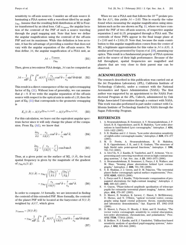
Fig. 11. PSF of two off-axis sources that are separated by 2λ=D and 4λ=D from the star.
200 J. Opt. Soc. Am. A / Vol. 28, No. 2 / February 2011 Pueyo et al.
sensitivity to off-axis sources. Consider an off-axis source il-luminating a PIAA system with a wavefront tilted by an angleγSky. Assume that the resulting field distribution at M2 is Four-ier transformed by an ideal lens. Call γCamera the angular loca-tion of the centroid of the PSF of such a source travelingthrough the pupil mapping unit. Note that here we definethe angular magnification using the centroid of the off-axisPSF and not its maximum. While this definition is less accu-rate, it has the advantage of providing a number that does notvary with the angular separation of the off-axis source. Wethus define M, the angular magnification of a PIAA unit, as
M ¼ γCamera
γSky: ðB1Þ
Then, given a two-mirror PIAA design,M can be computed as
This result is a direct consequence of the ray optics remappingfactor of Eq. (11). Without loss of generality, we can assumethat ϕ ¼ 0. If we write the angular separation of the off-axissource with respect to the optical axis in units of λ=D, then thepart of Eq. (11) that corresponds to the geometric remappingis
Eαð~r; ~θÞ ¼ Að~rÞei2πDγSkyðr0 cos ~θÞ ¼ Að~rÞei2πDγSkyx0ð~x;~yÞ: ðB3Þ
For this calculation, we leave out the equivalent angular spec-trum factor since it will only change the phase of the compa-nion. From Eq. (A1), we know that
∂x0∂ ~x
¼ r0~rAð~rÞ cos
2 ~θ þ ~rr0
sin2 ~θ; ðB4Þ
∂x0∂ ~y
¼�
r0~rAð~rÞ −
~rr0
�cos ~θ sin ~θ: ðB5Þ
Thus, at a given point on the surface of M2, ð~r; ~θÞ, the localspatial frequency is given by the magnitude of the gradientof γSkyx0ð~x; ~yÞ:
In order to compute M formally, we are interested in findingthe centroid of this extended PSF. More formally, the centroidof the planet PSF will be located at the barycenter of Nð~r; ~θÞweighted by Að~rÞ2, which gives
When we use a PIAA unit that follows the 10−10 prolate pro-file for Að~rÞ, this yields M ¼ 2:63. This is exactly the valuefound when measuring the angular magnification using simu-lations such as the one shown on Fig. 11, where we have com-puted the PSF of two off-axis sources, of respective angularseparation 2 and 4λ=D, propagated through a PIAA unit. Thecentroids of these PSFs appear in the final image plane at2 × 2:63 and 4 × 2:63λ=D. Note that, because the main contri-bution to this angular magnification comes from the center ofM2, a legitimate approximation for this value is M≃ Að0Þ. Asimilar proof was presented by Guyon et al. [19], assuming rayoptics. This result is a fundamental property of PIAA systemsand is the source of their high performance. Because of thefull throughput, spatial frequencies are magnified andplanets that are very close to their parent star can beobserved.
ACKNOWLEDGMENTSThe research described in this publication was carried out atthe Jet Propulsion Laboratory (JPL), California Institute ofTechnology (Caltech), under a contract with the NationalAeronautics and Space Administration (NASA). The firstauthor was supported by an appointment to the NASA Post-doctoral Program at the JPL, Caltech, administered by OakRidge Associated Universities through a contract with NASA.This work was also performed in part under contract with Ca-lifornia Institute of Technology funded by NASA through theSagan Fellowship Program.
REFERENCES1. A. Sivaramakrishnan, R. Soummer, A. V. Sivaramakrishnan, J. P.
Lloyd, B. R. Oppenheimer, and R. B. Makidon, “Low-order aber-rations in band-limited Lyot coronagraphs,” Astrophys. J. 634,1416–1422 (2005).
2. S. B. Shaklan and J. J. Green, “Low-order aberration sensitivityof eighth-order coronagraph masks,” Astrophys. J. 628, 474–477(2005).
3. M. D. Perrin, A. Sivaramakrishnan, R. B. Makidon,B. R. Oppenheimer, J. R., and J. R. Graham, “The structure ofhigh Strehl ratio point-spread functions,” Astrophys. J. 596,702–712 (2003).
4. A. Give’On, N. J. Kasdin, R. Vanderbei, and Y. Avitzour, “On re-presenting and correcting wavefront errors in high-contrast ima-ging systems,” J. Opt. Soc. Am. A 23, 1063–1073 (2006).
5. A. Sivaramakrishnan, R. Soummer, L. Pueyo, J. K. Wallace, andM. Shao, “Sensing phase aberrations behind Lyot corona-graphs,” Astrophys. J. 688, 701–708 (2008).
6. S. B. Shaklan, J. J. Green, and D. M. Palacios, “The terrestrialplanet finder coronagraph optical surface requirements,” Proc.SPIE 6265, 62651I (2006).
7. L. Pueyo and N. J. Kasdin, “Polychromatic compensation of pro-pagated aberrations for high-contrast imaging,” Astrophys. J.666, 609–625 (2007).
8. O. Guyon, “Phase-induced amplitude apodization of telescopepupils for extrasolar terrestrial planet imaging,” Astron. Astro-phys. 404, 379–387 (2003).
9. D. Mawet, E. Serabyn, K. Liewer, C. Hanot, S. McEldowney,D. Shemo, and N. O’Brien, “optical vectorial vortex corona-graphs using liquid crystal polymers: theory, manufacturingand laboratory demonstration,” Opt. Express 17, 1902–1918(2009).
10. D. Mawet, L. Pueyo, D. Moody, J. Krist, and E. Serabyn, “Thevector vortex coronagraph: sensitivity to central obscuration,low-order aberrations, chromaticism, and polarization,” Proc.SPIE 7739, 773914 (2010).
11. R. Belikov, N. J. Kasdin, and R. J. Vanderbei, “Diffraction-basedsensitivity analysis of apodized pupil-mapping systems,” Astro-phys. J. 652, 833–844 (2006).
Pueyo et al. Vol. 28, No. 2 / February 2011 / J. Opt. Soc. Am. A 201
12. S. B. Shaklan, A. Give’on, R. Belikov, L. Pueyo, and O. Guyon,“Broadbandwavefront control in a pupil mapping coronagraph,”Proc. SPIE 6693, 66930R (2007).
13. W. A. Traub and R. J. Vanderbei, “Two-mirror apodization forhigh-contrast imaging,” Astrophys. J. 599, 695–701 (2003).
14. R. J. Vanderbei, “Diffraction analysis of two-dimensional pupilmapping for high-contrast imaging,” Astrophys. J. 636, 528–543(2006).
15. E. A. Pluzhnik, O. Guyon, S. T. Ridgway, F. Martinache, R. A.Woodruff, C. Blain, and R. Galicher, “Exoplanet imaging witha phase-induced amplitude apodization coronagraph III. Hybridapproach: optical design and diffraction analysis,” ArXiv Astro-physics e-prints 0512421 (2005).
16. L. Pueyo, “Broadband contrast for exo-planet imaging: the im-pact of propagation effects,” Ph.D. thesis (Princeton University,2008).
17. L. Pueyo, S. B. Shaklan, A. Give’on, and J. Krist, “Numerical pro-pagator through PIAA optics,” Proc. SPIE 7440, 74400E (2009).
18. S. B. Shaklan and J. Green, “Reflectivity and optical surfaceheight requirements in a broadband coronagraph. 1.Contrastfloor due to controllable spatial frequencies,” Appl. Opt. 45,5143–5153 (2006).
19. O. Guyon, E. A. Pluzhnik, R. Galicher, F. Martinache,S. T. Ridgway, and R. A. Woodruff, “Exoplanet imaging witha phase-induced amplitude apodization coronagraph. I. Princi-ple,” Astrophys. J. 622, 744–758 (2005).
202 J. Opt. Soc. Am. A / Vol. 28, No. 2 / February 2011 Pueyo et al.