PROCEEDINGS OF HIIE IRE Propagation of the Low-Frequency Radio Signal* J. RALPH JOHLERt, SENIOR MEMBER, IRE The following paper was solicited for the PROCEEDINGS by the Tutorial Subcommittee of the IRE Wave Propagation Committee, and appears below as a part of a continuing program of presenting review and tutorial papers on subjects of general interest and im- portance. The Editor Summary-The propagation of a radio signal and the propagation in the time domain is reviewed for linear amplitude systems. The particular case of the propagation of a ground wave pulse is con- sidered in detail. A stretching in the form or shape of the pulse is noted as a result of the filtering action of the propagation medium. Theoretical transfer characteristics for the media of propagation of LF signals are introduced and methods of computation are con- sidered. The particular case of a signal transmitted between two points on the earth's surface is considered from the viewpoint of propagation in the time domain. The field of LF waves propagated around the earth is, in large measure, influenced by the reflection and transmission processes at the ionosphere. Such processes are evaluated theoretically with the aid of Maxwell's equations together with an equation which describes the electron motion in the presence of a static magnetic field, a superposed electrodynamic field together with mechanical collisions between electrons and ions, such as the Langevin equation of motion of the electron. The use of full mathematical rigor in the application of these equations is feasible and indeed desirable at LF. Thus, the application of these equations to an electron-ion model plasma with arbitrary orientation of the superposed magnetic induction results in anisotropic transmission and reflection properties. The full rigor can be applied to model plasmas in which the electron density and collision frequency vary with altitude. This leads to the notion of reflection and transmission at a continuously stratified plasma. Four distinct magneto-ionic propagation components exist in the ionosphere. These can be identified as ordinary and extraordinary, upgoing and downgoing waves. All of these propagation components are coupled to each other as the electron density changes with penetration depth into the plasma. The anisotropy as a result of the electron gyration (Lorentz force) caused by the superposed static magnetic field of the earth clearly introduces a nonreciprocity in the propagation of the field between transmitter and receiver since the ionosphere reflection coefficient would not in general be the same if transmitter and re- ceiver were interchanged. The nature of the signal as a result of ionospheric propagation can be determined from the CW field with the aid of the Fourier transform-integral techniques employed on the ground wave in detail. I. INTRODUCTION T HE ELECTRICAL properties of the ground, the ionosphere, the space between the ground and the ionosphere, and outer space determine the propa- *Received by the IRE, October 23, 1961; revised manuscript received, January 29, 1962. This work was sponsored by the U. S. Air Force as part of Tasks 4 and 5 of the Rome Air Development Center, D.O. AF30-(602)-2488, March, 1961. t National Btureau of Standards, Boulder, Colo. gation of low-frequency (LF) electrom-lagnietic waves in the vicinity of the earth. The electrical properties of these media (Fig. 1) are by convention described in concise form by means of the angular wave number k=ki, k2, k3, * - , written k=-qw/c, which involves the index of refraction 7 =7 1, 2, .7 3 * *, the angular fre- quency w = 27rf, and the speed of light c'-3(105) m/sec. A time-harmonic electromagnetic wave, i.e., a wave whichi oscillates harmonically in time t from t = -o to t= + oo (a wave uninterrupted in time) can be de- scribed in terms of the electric field E, volts/meter, E = |E| exp (iwt -ikD), at a distance D when such a wave is propagated through a particular medium k of infinite extent. T he principal task of the theoretician in the development of a de- scription of the propagated field comiiprises the deter- miination of the wave niumber or index of refraction from the electrical properties of the medium, applyinig Maxwell's equations for the propagation of electromag- netic fields E, H (H = electrodynamic miagnetic field) to the boundaries between and within the various imedia and introducing the nature of the source of the radia- tion. In the past, attention has been focused upoIn the propagation of these waves around the surface of the earth taking account of the grounid, the ionosphere anid the space between the ground and the ioniosphere. Re- cently, as might be expected, considerable interest has developed in the propagation of LF waves in outer space, anid there seems to be little doubt that interest in this type of propagationi will inicrease with time. The theoretical treatmenit of low frequencies ap- parently differs quite markedly from the theoretical treatment usually employed at high frequenicies as to the degree of mathematical rigor. Indeed, the mathe- matical rigor required for a theory of propagationi of radio waves in the vicinity of the earth increases rapidly as the frequency is decreased. This is not difficult to appreciate intuitively since the wavelength becomes quite long and eveni approaches in magniitude certaiin critical dimensionis of the mediunm at I 'VLF, such as the altitude of the lower boundary of the ionosphere 404 A pril
Transcript
PROCEEDINGS OF HIIE IRE
Propagation of the Low-Frequency Radio Signal*J. RALPH JOHLERt, SENIOR MEMBER, IRE
The following paper was solicited for the PROCEEDINGS by the Tutorial Subcommitteeof the IRE Wave Propagation Committee, and appears below as a part of a continuingprogram of presenting review and tutorial papers on subjects of general interest and im-portance. The Editor
Summary-The propagation of a radio signal and the propagationin the time domain is reviewed for linear amplitude systems. Theparticular case of the propagation of a ground wave pulse is con-sidered in detail. A stretching in the form or shape of the pulse isnoted as a result of the filtering action of the propagation medium.Theoretical transfer characteristics for the media of propagation ofLF signals are introduced and methods of computation are con-sidered. The particular case of a signal transmitted between twopoints on the earth's surface is considered from the viewpoint ofpropagation in the time domain.
The field of LF waves propagated around the earth is, in largemeasure, influenced by the reflection and transmission processes atthe ionosphere. Such processes are evaluated theoretically with theaid of Maxwell's equations together with an equation which describesthe electron motion in the presence of a static magnetic field, asuperposed electrodynamic field together with mechanical collisionsbetween electrons and ions, such as the Langevin equation of motionof the electron. The use of full mathematical rigor in the applicationof these equations is feasible and indeed desirable at LF. Thus, theapplication of these equations to an electron-ion model plasma witharbitrary orientation of the superposed magnetic induction results inanisotropic transmission and reflection properties. The full rigorcan be applied to model plasmas in which the electron density andcollision frequency vary with altitude. This leads to the notion ofreflection and transmission at a continuously stratified plasma.
Four distinct magneto-ionic propagation components exist in theionosphere. These can be identified as ordinary and extraordinary,upgoing and downgoing waves. All of these propagation componentsare coupled to each other as the electron density changes withpenetration depth into the plasma.
The anisotropy as a result of the electron gyration (Lorentzforce) caused by the superposed static magnetic field of the earthclearly introduces a nonreciprocity in the propagation of the fieldbetween transmitter and receiver since the ionosphere reflectioncoefficient would not in general be the same if transmitter and re-ceiver were interchanged.
The nature of the signal as a result of ionospheric propagationcan be determined from the CW field with the aid of the Fouriertransform-integral techniques employed on the ground wave indetail.
I. INTRODUCTIONT HE ELECTRICAL properties of the ground, the
ionosphere, the space between the ground and theionosphere, and outer space determine the propa-
*Received by the IRE, October 23, 1961; revised manuscriptreceived, January 29, 1962. This work was sponsored by the U. S.Air Force as part of Tasks 4 and 5 of the Rome Air DevelopmentCenter, D.O. AF30-(602)-2488, March, 1961.
t National Btureau of Standards, Boulder, Colo.
gation of low-frequency (LF) electrom-lagnietic waves inthe vicinity of the earth. The electrical properties ofthese media (Fig. 1) are by convention described inconcise form by means of the angular wave numberk=ki, k2, k3, *- , written k=-qw/c, which involves theindex of refraction 7 =7 1, 2, .73 * *, the angular fre-quency w = 27rf, and the speed of light c'-3(105) m/sec. Atime-harmonic electromagnetic wave, i.e., a wave whichioscillates harmonically in time t from t = -o tot= + oo (a wave uninterrupted in time) can be de-scribed in terms of the electric field E, volts/meter,
E = |E| exp (iwt -ikD),
at a distance D when such a wave is propagated througha particular medium k of infinite extent. The principaltask of the theoretician in the development of a de-scription of the propagated field comiiprises the deter-miination of the wave niumber or index of refractionfrom the electrical properties of the medium, applyinigMaxwell's equations for the propagation of electromag-netic fields E, H (H = electrodynamic miagnetic field)to the boundaries between and within the various imediaand introducing the nature of the source of the radia-tion.
In the past, attention has been focused upoIn thepropagation of these waves around the surface of theearth taking account of the grounid, the ionosphere anidthe space between the ground and the ioniosphere. Re-cently, as might be expected, considerable interest hasdeveloped in the propagation of LF waves in outerspace, anid there seems to be little doubt that interestin this type of propagationi will inicrease with time.The theoretical treatmenit of low frequencies ap-
parently differs quite markedly from the theoreticaltreatment usually employed at high frequenicies as tothe degree of mathematical rigor. Indeed, the mathe-matical rigor required for a theory of propagationi ofradio waves in the vicinity of the earth increases rapidlyas the frequency is decreased. This is not difficult toappreciate intuitively since the wavelength becomesquite long and eveni approaches in magniitude certaiincritical dimensionis of the mediunm at I 'VLF, such asthe altitude of the lower boundary of the ionosphere
404 A pril
Johler: Propagation of Low-Frequency Signal
.9
,l
Xr-sX \ I a ' r/ c- o t
Optcal Horizon
"0 \T1/ "/Surfoceof
/_Centerof ohere
the Earth
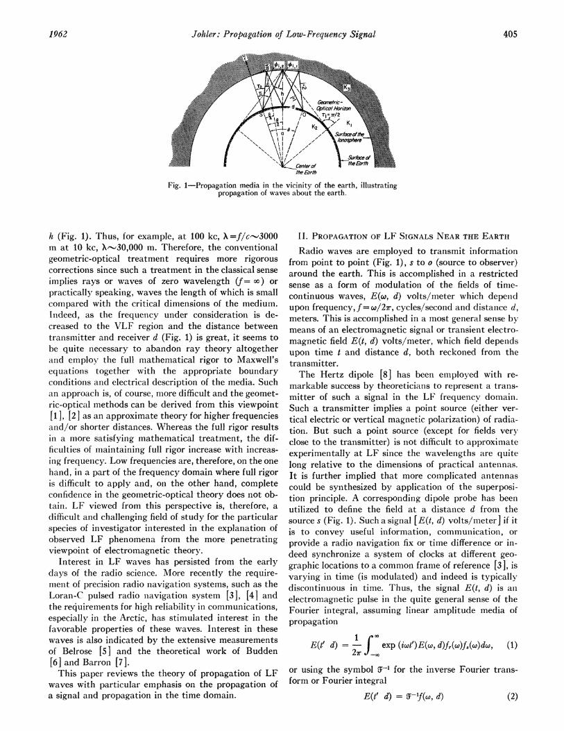
Fig. 1-Propagation media in the vicinity of the earth, illustratingpropagation of waves about the earth.
h (Fig. 1). Thus, for example, at 100 kc, \=f/cc---.3000m at 10 kc, X-30,000 m. Therefore, the conventionalgeometric-optical treatment requires more rigorouscorrections since such a treatment in the classical senseimplies rays or waves of zero wavelength (f= oo) orpractically speaking, waves the length of which is smallcompared with the critical dimensions of the medium.Indeed, as the frequency under consideration is de-creased to the VLF region and the distance betweentransmitter and receiver d (Fig. 1) is great, it seems tobe quite necessary to abandon ray theory altogetherand employ the full mathematical rigor to Maxwell'sequations together with the appropriate boundaryconditions and electrical description of the media. Suchan approach is, of course, more difficult and the geomet-ric-optical methods can be derived from this viewpoint[I], [2 ] as an approximate theory for higher frequenciesand/or shorter distances. Whereas the full rigor resultsin a more satisfying mathematical treatment, the dif-ficulties of maintaining full rigor increase with increas-iIng frequency. Low frequencies are, therefore, on the onehand, in a part of the frequency domain where full rigoris difficult to apply and, on the other hand, completeconfidence in the geometric-optical theory does not ob-tain. LF viewed from this perspective is, therefore, adifficult and challenging field of study for the particularspecies of investigator interested in the explanation ofobserved LF phenomena from the more penetratingviewpoint of electromagnetic theory.
Interest in LF waves has persisted from the earlydays of the radio science. More recently the require-ment of precision radio navigation systems, such as theLoran-C pulsed radio niavigation system [3], [41 andthe requirements for high reliability in communications,especially in the Arctic, has stimulated interest in thefavorable properties of these waves. Interest in thesewaves is also indicated by the extensive measurementsof Belrose [5 ] and the theoretical work of Budden[6] and Barron [7].This paper reviews the theory of propagation of LF
waves with particular emphasis on the propagation ofa signal and propagation in the time domain.
II. PROPAGATION OF LF SIGNALS NEAR THE EARTH
Radio waves are employed to transmit informationfrom point to point (Fig. 1), s to o (source to observer)around the earth. This is accomplished in a restrictedsense as a form of modulation of the fields of time-continuous waves, E(co, d) volts/meter which depenidupon frequency, f= co/2r, cycles/second and distance d,meters. This is accomplished in a most general sense bymeans of an electromagnetic signal or transient electro-magnetic field E(t, d) volts/meter, which field depeiidsupon time t and distance d, both reckoned from thetransmitter.The Hertz dipole [8] has been employed with re-
markable success by theoreticians to represent a trans-mitter of such a signal in the LF frequencv domain.Such a transmitter implies a point source (either ver-tical electric or vertical magnetic polarization) of radia-tion. But such a point source (except for fields veryclose to the transmitter) is not difficult to approximateexperimentally at LF since the wavelengths are quitelong relative to the dimensions of practical antennas.It is further implied that more complicated antennascould be synthesized by application of the superposi-tion principle. A corresponding dipole probe has beeniutilized to define the field at a distance d from thesource s (Fig. 1). Such a signal [E(t, d) volts/meter] if itis to convey useful information, communication, orprovide a radio navigation fix or time difference or in-deed synchronize a system of clocks at different geo-graphic locations to a common frame of referenice [3], isvarying in time (is modulated) and indeed is typicallydiscontinuous in time. Thus, the signal E(t, d) is anelectromagnetic pulse in the quite general sense of theFourier integral, assuming linear amplitude media ofpropagation
E(t' d) exp (iwt')E(w, d)fr(c)f8(w)do, (1)27r co
or using the symbol i-l for the inverse Fourier tranis-form or Fourier integral
E(t' d) = i-f(, d) (2)
1962 405
PROCEEDINGS OF THE IRE
where f(w, d) is the complex Fourier transfornm of asignal. The source transform f9(cw) is determined fromthe time domain F,(t) by the direct transformationi
f4w(@)- J exp (-iwt)F,(t)dt (3)
or
J8(W) -JF,(t) (4)
where the source F8(t) represents a Hertz dipole currentmoment, 101 ampere-miieters as a funiction of universalsource time t and the CW field E(w, d) represents thecomplex transfer characteristic of the propagationmedium. Since practical systems for the transfer of in-formation affect the signal, it is necessary to introducethe complex transfer characteristic of the systeimi (prini-cipally the receiver) fr(w).i The local time t' [91 isreckoned locally from the beginninig of the first pre-cursor [lo], [11] of the pulse, which cani arrive at apoinit o (Fig. 1) no sooner thani a signal propagated overthe distance d at the speed of light c, but which will ingeneral arrive later. Thus,
t' =t - ndlc (5)
where i-l (for air, n71-1.000338 typically at the sur-face of the earth).The completely degenierate case of a signail varying
harmonically in time from niegative to positive infinity(t= -oo to t-= + xc) is a very special situation whichcan convey theoretically zero informationi between thepoint s, the transmitter, and the receiver o (Fig. 1),
E(t'd) ' E(co, d), (6)
but which is nonetheless frequently employed as aniapproximation for "narrow bandwidth" communica-tion systems with the inferenlce that such systems aresatisfactorilv described by the "zero bandwidth"asymptote and where the notion of bandwidth implies afinite spectrum of frequencies f(w, d). Indeed, nmosttheoretical calculations of the field E evaluate thistransform E(c, d) with the imiplication that such afunction, evaluated over all frequenicies of concern inthe Fourier integral (1) from negative to positive in-finity, together with a specification of the source as afunctioni of time [f(t) I yield the niature of the propa-gated sigiial.
III. PUILSES AND PROPAGATION IN TIIE TIrmEI DomAINThe theoretical notion of the signal as a pulse imiiplies
importanit consequences as to the interpretationi ofpropagation in the time domnaini. This can be nmorereadily explained from the viewpoint of geonmetric-optics. Indeed, the use of full mathematical wave theoryrigor would yield the same general conclusionis as thosewhich are reached with the aid of geometric-optics.A signal transmitted arounid the earth between two
points (Fig. 1) s to o, could arrive at the point o, ac-
cordinig to the principle of relativity, nio soonier thani asignial tranismitted at the speed of light over some raylenigth D. This poin-t was established imlanly years ago(1914) by Somimiiierfeld [10] aidiBrillouini [It'] in a pairof mleimiorable papers whiclh established the conisisteilcyof electromagnetic t-heorN with relitivity. WNhereas theCXW conicepts of phase velocity an(d group velocity inthe presenice of aniomIolouLs (lispersiol) gave velocitieswhich varied betweenl positive an(dl negative infinity,the full transieint solutioni demonistratedl that a lightwave signal velocity properlv definied(was always lessthan the speed of light and thuis conisistenit with theprinciple of relativity. Therefore, the shortest "rayx"(Fig. 1) has a length D=d, the distanice alonig the sur-face of the earth (since waves in the earth atre com-pletely absorbed). The first wave to arrive at the re-ceiver o is then the ground wave j-0. Other waves willarrive later as a result of propagation over soimie dis-tanice such as D=Dj where j=1, 2, 3, (Fig. 1)and correspondinigly arrive at the receiver at ever latertimes t= tj. This fact is not obvious to the observer of aLCW "signal" [E(w, d)] since such a signial cannot re-solve the individual ordered rays j which arrive at thereceiver. Thus, the observer sees on1v the resultanitvector field E(w, d) of the suII1 of a inumllber of individualfields Ej(w, d) of each ordered ray
I)
EA(w, d) ZEj(w, d), j 0) 1, 2,3, * (7)j-0
in which the zero order field j=0 is the ground waveand each higher order field j=1, 2, 3, orj0 cor-responds to ionospheric waves or waves reflected by theionosphere [12],
where Eo(w, d) = Eo(o, d) exp [-i(wb +4)c) ], consider-ing 4, a phase lag or phase correction [13], and simi-larily, the local ionospheric wave timle or ionosphericwave delay
t/'(j= 1,2,3, )is,(12)
(13)
The quantity bj-b, a time, is called the relative iono-spheric wave delay, Fig. 2 (relative to the grounid wave).The physical length of the particular type of ray Djrepresented in Fig. 1 (other types of rays are feasible)can be evaluated geometrically for a reflectioni at ani
Fig. 2-Relative skv-wave delay for various altituide h ofthe lower ionosphere boundary.
DISTANCE, d/j, STATUTE MILES
altitude h above the surface of the earth of radius a,
Di = 2j[(a + h) cos i,, - a cos rj], (14)
where (Fig. 1) + is the aingle of incidence of the ray onthe ionosphere and rj is the corresponding angle of in-cidence on the earth and the subscript j reminds thereader that the equation refers to a particular iono-spheric wave (j=1, 2, 3, - ) or ground wave (j=0)under consideration. The angles &5i and rj are evaluatedquite simply from the geometry. If,
A [[2a(a + h) (- cos + h2] then (15)
sin O j = Aj-'a sin-, (16)2i
cosOi j = A,1 [a(1-cosi) +h], (17)
0sin rj = A1'(a + h) sin- (18)
2j
cosrj=A- [a (cos--1) + k cos-j (19)
where 6 (Fig. 1) is the angle at the center of the earthsubtended by the distance d along the surface of aspherical earth, or simply d = a@. The relation betweendistance d/j, angle of incidence 4i, and height h of thelower boundary of the ionosphere can therefore bequite simply illustrated as in Fig. 3.The transmitting and receiving antenna factors GC
have been included to take account of antennas otherthan Hertz dipoles, where for the particular case of avertical magnetic Hertz dipole Gj=1 in the equatorialplane of the dipole an-d Gj=sin rj for the vertical elec-trical dipole.The geometric-optical theory permits the use of plane
reflection coefficients or Fresnel type reflection coef-ficients for rays reflected at the ground (Fig. 1) or theionosphere. However, the ionosphere is not plane and itis necessary at low frequencies to introduce certainspherical corrections to the geometric-optical theory.The relation between plane and spherical reflections isdefined by the convergence-divergence coefficient aj
Fig. 3--Geometric-optical relation between the angle of incidence c/distance from the source d/j, j= 1, 2, 3, * , j O, and the alti-tuide h of the lower boundary of the ionosphere.
which converts the former to the latter or from the view-point of the ray theory, takes account of ray focusingby the ionosphere and a corresponding defocusing ofrays by the earth. Bremmer [1 ] has developed for-mulas for such a correction. A modification of thisfocusing or convergence correctioni Aj has been de-veloped by Wait [14] to take account of rays near thegeometric-optical horizon rji-r/2 and beyond. Thecomplete expression can be written
j (1 + /a[(21 sin- / sin0]1/2
x {[a(1-cos 2 ) +ih]
/ (a + h) cos- - a A3 , (20)
in which Aj can be evaluated from the cylindricalHankel function of order n= 1 of the second kind, whichfor j=1 can be written
Aj (, Zj) H11/3 (2) ) exp I-i[5r/12 -Zj}
whereZ; = kia cos3 Tr/3 sin2 rl.
(21)
(22)
Wait [14] has developed numerous graphs of the func-tion aj and Aj and Johler [12] has detailed some com-putation methods, especially for the Hankel functionH113(2)(z)-The factor Fj is an antenna pattern factor since it
describes a plane wave incident on a sphere with a re-ceiver dipole antenna located on the surface of thesphere. The factor Fj accounts for the presence of thespherical earth at both the transmitter Fjt and the re-ceiver Fjr, and if it can be assumed that the geometric-optical ray is not too close or beyond the geometric-optical horizon (Fig. 1), the Fresnel approximationagain sufficies to determine Fj, or for vertical polariza-tion
I I
ee i-1-
:1!Q.-- -- -.- -- .-- .-- --- - .- --- ---
-
1962 407
!.
\!--
-4-
PROCEEDINGS OF THE IRE
Fj - [I + Ret(Tj)][I + Rer(Tj)] (23)
where the superscripts t and r refer to the transmiiitterand receiver respectively, and the subscript e refers tovertical electric polarization anid
Re(Jrj) k22 cos Tj/k12- [k22/k12 -sin2 Tj]I/ }
/{ k22 cos rj/k12 + [k22Ilk12 -sin2 rj l/2[, (24)
or for horizontal polarizationi
Re,n(Tj) = cos rj - [k22 12 - sin2 Tj] /2}
C Tj + [k22/k12 - sin2 rT] 1/2} (25)
where
k2 - 2- I/2
c _
C CC C
receiver. Wait [15] has developed curves of this funic-tioIn and some computationi methods have beeni OlIt-lined by Johler [12 ]. Close to, but beyon-d the geomiietric-optical horizon, the factor Fj= F(F,";t Clcan be evaltiatedas noted by Wait [15]. A residue series sumnmiiationi [12-1
- 2iV/ir exp [-ikl(d - di)]X exp [-i(kia)1/30'-r]
S U( (2 113T - q2)lW(2'11r,)(31)
where the permittivity lapse factor a, which takes ac-equation of Riccati, noted by7 Bremmller anid tabulatedby Johler, et al., [16]
db--262r + 1 = 07d,r(26)
which definies the wave iiuiiber of the air and theground in terms of the dielectric constant E2 relative toa vacuum, the conductivity, a, mhos/m and the per-meability yo=4wr( 1-7) h/m. The dielectric constanit isE2=15 for typical land and e2=80 for sea water; alsoor= 0.005 and 5 mhos/m for land anid sea water respec-tively. Here again it has beeni found necessary to correctthe rays near and beyonid the geometric-optical horizonTy-T-'r/2. A contour initegral developed by \Vait [15]can be employed close to the geometric-optical horizonfor the calculation of Fj= Fj/Fjr:
These restrictions on arg p make all functions involvedsingle valued. Note that a separate conductivity a anddielectric constant E2 can be ascribed to transmitter and
(32)
where the factor 6 (which depends oni dielectric constanitE2 anid coniductivitv g) for vertical electric polarizationof the Hertz dipole 8 = ,
-ik22a'/3 Ik12be =
-1k2
(33)
where the permittivity lapse factor a, which takes ac-counit of the variation in inidex of refractioni of theatmosphere with altitude is a'-0.75 to 0.85. Howe[17], Johler, Walters, anid Lilley [16], and Walters anidJohler [18] have developed methods for taking thespecial roots T= T, of (32), where the limiiiting rootsa=0, a= o are found from
H2,3(2)[4(-2rs)3I2] = 0,
H113(2) ['-2,)3/2] = 0,s = 0, 1, 2, 3 * * .
8 e oO
be = 0,(34)(35)
The reflection process at the ground and the iono-sphere is represented (8) in concise form Cj, according toBremmer [I], for the case of a vertically polarizedtransmitter and receiver (Fig. 4).
where Re and Rm are the conivenitional Fresnel ground(lreflection coefficients for plane waves of angle of ini-cidence rj (Fig. 1) of both vertical anld horizontalpolarization respectively, and the 7"s represent, theioniosphere reflection coefficients for planie waves witlhangle of incidenice Oi; thus, the essential nature of thepropagation of the CW signal around the earth via theionosphere can be described in terms of four reflectionicoefficients Tee, Te, Tine, Tim The reflection coefficienitTee refers to vertical electric polarizationi of the incidenit
408 .1 pril
Johler: Propagation of Low-Frequency Signal
- Ray Indicating Electric Vectorin Plane of Vertical Electric Sourteand Observor Dipoles
--- Ray Indicating Magnetic Vectorin Some Plane
Hm Ns V0
I-
plane wave and a similar vertical electric polarization ofthe reflected wave. The coefficient Ter describes thegeneration of the abnormal component by the incidentvertical polarization (reflected horizontal electric po-larization for vertical electric excitation). Similarly,Trm refers to the incident horizontal electric polariza-tion and the corresponding reflected horizontal electricpolarization. Also, the abnormal component of thehorizontal electric polarization (reflected vertical elec-tric polarization for horizontal electric excitation) is de-scribed by the coefficient Tine. Referring these mattersto a local coordinate system (Fig. 5) at the ionospherelower boundary [12], [19], [20],
Tee = Ey'r/Ey'isTem = Ex'r/Ey'i
Trmn-= Ex'r/Ex,ijTmie = EyrlExt (37)
Hm,tl,N,9 V HM,2, N2t V2
E 0 W 0,P 0 E 0
v - R - -r-
cr, E2
Hm,1, Ni,1Vi Hm,21 N2' V2 HM,3, N3 Z3
E Ev EE 00*,we EEE ow E Es
,n,~~ ~ /
E E 0 E 0cc r cr sl: tz: {k
crI,' 2,1 (2, l2,2
Hm,l Nj, 1/1 HM,21 N2, 1/2 Hm,3, N31 V3 Hm 49N4,
1')~~ ~~~~~N / \\ //)^^^^^
£V E E E 0 E E 0 E @ 0 w @ 0 0we E E _|_E E we E EFwe EFvE;E
_ _ M CY to to n o g
E vE EEEwEOEEwc: cr a:. cr ta:Cr_ :zc. :. cr.r :zrc
0-i , I2, 07. (62,2 O3.- 62,3
Fig. 4-Geometric-optical ray propagation mechanism, illustratingthe development of the factor C3 and illustrating coupling exteriorto the ionosphere as a consequence of the generation of the abnor-mal components.
where the subscripts i or r refer to the incident and re-flected wave, respectively, at the lower boundary of theionosphere. The techniques for evaluating the reflectioncoefficients for an anisotropic model electron-ion plasmaare quite complicated and will be discussed later.The ground wave CW, Eo(w, d) (i.e., the zero order
ray j=0 can be evaluated from the classical series ofresidues) formulated by Bremmer can be written in theform [1], [13 ], [23 ] for vertical electric polarization
where s=0, 1, 2, 3, * * *, C is given by (9), and againa-0.75 to 0.85 and 6, Sr have been defined (32), (33).A horizontally-polarized Hertz dipole radiation field
can also be found (vertical magnetic field, HI, ampere-turns/meters) simply by replacing be by 6l. &.. = 6,ki/k2re-evaluating ,r and substituting in (38).The notion of a CW signal E(o, d) as the vector sunm
of individual rays ordered in timne (7) is obscure to theobserver of such a signal. However, a signal in the truesense, i.e., oIne which can convey informationi and heniceis interrupted in the time domain, manifests the indi-vidual propagation rays. The Fourier integral (1) for apulse transmission can be rewritteni as a consequence ofpropagation of such signials E(t, d),
p
E(t', d) = > Ej(t'1, d)j=oP 1 C0X
= exp (iwt'j)Ej(w, d)fr((w)f8(&)dw. (39)j7o 27r _
This merely represents the sum of separate Fourier in-tegrals for each ray, separated in time by the iono-spheric wave delay t'j.The signal E(t', d), (1), (39) which has been de-
scribed in the time domain, is in general complex if com-plex source functions Fj(t), (3) are employed. The signal
1962 409
$_
L-.;-
PROCEEDINGS OF THE IRE
Fig. 5-Local coordinate system for ioniosphere botundary.
d 858 MILES
t' MICROSECONDS
d_o MILES
I MICROSECONDS
LLwI-wNC,)-J0>
-o
w0L)r
d-662 MILES cr. d=d858 MILESwwNC,)
w-r
0 4 00Q& 1M=ICRO ECN
tl MICOECODStI MICROSECONDS
- ,o
W N
-,.
U)
i0 h
w-1w
aL)+1
d = 512 MILES a:ww
(I)
~0
i:riQ)cc
d_-O MILES
0
tI' MICROSECONDS
t' MICROSECONDS
(a) NIGHTTIME (b) NIGHTTIME
Fig. 6-Observations of propagated pulses of various lengths illustrating the time separation of the grounid wave (j =0) and the various iono-spheric reflections (j= 1, 2, 3, * * - ). The measurement of a point in tinme oni the leading edge of the pulse with the amplitude envelopeminus the derivative of the amplitude envelope method is also illustrated (b, d=512). (Oscillograms traced frorn original photographs ofJuly-August, 1953, CYTAC/Loran-C field tests).
410 A pril
wwN.
a1)
N
-C
a.
Li}:
W/v\/V
F100
(C) DAYTIME
I
Johler: Propagation of Low- Frequency Signal
which is observed anid recorded as an oscillogram, forexample, is typically the real part of the complex field,Re E(t', d), while the amplitude E(t', d) |, can representsome sort of einvelope detection process in the receiver.Thus, an envelope can be synthesized with the aid of acomplex source and propagated with the signal as anindex of the pulse dispersion (change in forimi or shape)as a result of the propagation.The physical notion of a signial observed at a poinit o
(Fig. 1) as the sum of ordered rays in the time domainis illustrated [21 ] in Fig. 6 for various length pulses em-ployed during the development of the Cytac/Loran-Csystem [22]. The pulse radiated at the source, undis-turbed by the ionospheric time rays (pure ground wave)is shown as oscillogramns [Re E(t', d) ] at short distances.The action of the propagation medium on the signal isdemonstrated by the complicated, multiple (j=0, 1, 2,3, * 3), overlapping pulses observed at great dis-tances. Thus, the oscillogram or amplitude-time func-tion Re E(t', d) observed at a great distance comprisesthe overlapping individual signals Ej(t', d), j=0, 1, 2,3,t-- - , apparently added together according to thecomplex field specification Ej of each and separated intime by the ioniospheric wave delay t'j of each ray j or-dered in the time domain j=0, 1, 2, 3, . . . . The ap-proximate area in the amplitude-tinie plane occupiedby each ordered ray is showni in Fig. 6. Areas of overlapin which both constructive and destructive interferencebetween cycles of the multiple pulses produce notches.Enhancements in the composite pulse canl be observed.
Notwithstanding the areas of overlap, the instru-mentationi has been developed which can sort out theindividual ordered rays Ej(w, d), j=0, 1, 2, 3, * , inthe time domain and study or measure the amplitude,phase and dispersion of these individually [3], [4],[22]. Thus cycles and minute fractions of a cycle can bemeasured by tagging a poinit in time on the pulse. Onesuch method utilizes the amplitude envelope and henceemploys amplitude envelope detection. In effect, themethod forms the difference between the amplitudeenvelope E(t', d)| and the derivative dIE(t',d) jdt',and an elaborate null seeking device [4] seeks out aniull point or zero crossing for the time function so de-sired, thus determi-ninig a time-root T, of the differentialequation
dF(t',d) = clI E(t',d)j -C2 -, E(t', d)j 0, (40)
dt'
where cl and C2 are coinstanits which move the point intime which is to be tagged oni the pulse, such as the timegate shown on Fig. 6(b), which can be set by the oper-ator to pick out a particular point on the pulse. Bothamplitude and time (phase) can be measured at such a
point. Additional techniques are used to detect cyclesand minute fractions of a cycle under the envelope oInthe leading edge (pure ground wave signal) or elsewhere
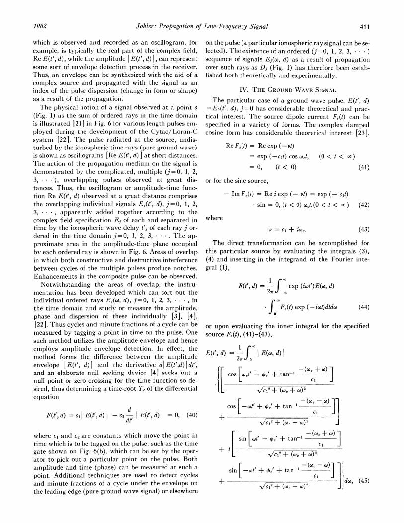
on the pulse (a particular ionospheric ray signal can be se-lected). The existence of an ordered (j=0, 1, 2, 3, )sequence of signals Ej(w, d) as a result of propagatioinover such rays as Dj (Fig. 1) has therefore been estab-lished both theoretically and experimentally.
IV. THE GROUND WAVE SIGNAL
The particular case of a ground wave pulse, E(t', d)=Eo(t', d), j=0 has considerable theoretical and prac-tical interest. The source dipole current F8(t) cain bespecified in a variety of forms. The complex dampedcosine form has considerable theoretical interest [23].
- Im F,(t) = Re i exp (- vt) = exp (- cit)sin=0, (t <O) Wct,(0 < t < oo) (42)
where
V = C1 + iwc. (43)
The direct transformation can be accomplished forthis particular source by evaluating the integrals (3),(4) and inserting in the integrand of the Fourier inte-gral (1),
E(t', d) = - exp (iwt')E(w, d)27r 0
co
J F,(t) exp (-iwt)dtdw (44)
or upon evaluating the inner integral for the specifiedsource F8(t), (41)-(43),
E(tI, d) = J E(w, d)|
fF cos F(.1i' + tan-1 (
VIC12 + (UC + I)2
cos [-co' + + tan-' -(cli;-+ VC2 + (Wc- W)2
+i- ~ ~ ~+ [sin [W' - c/~'+ tan-' -(C+
- -\IVC,2 + (CC + I)2
sin [-ct' + 4'' + tan-'
+ |lL d@, (45)
1962 411
PROCEEDINGS OF THE IRE
VERTICAL ELEC'
I ! i '!Il~~ ~ ~ ~I
o. 0.-
I0
Frequency, f, Cycles
Fig. 7-Amplitu(le transfer characteristic ofthe ground wave.
Frequency, f, Cycles
Fig. 8- Phase tranisfer (characteristic of the grouniid wave.
Note fx(w.d) fx(w.d)| exp Li 1(w.d)],The Fourier Spectrum CL
./
Time,t'
Fig. 9-Integrand of Fourier integral or image of pulse in the fre-quency-amplitude plane at small distance from the source, illus-trating the relation of the integrand to the Fouirier spectrumwaves.
412 April
a,-2
.2
LL-i
r
2C:
:2LuLL-
Johler: Propagation of Low-Frequency Signal
where q5'=-45-7r/2=arg [E(co, d)] and E(co, d)=Eo(w, d)..The real part of the amplitude-time function (45) Re
E(ti', d) is the desired function for the cosine source (41),and the imaginary part -Im E(t', d) = Re [iE(t', d) ] isthe desired function for the sine source (42). This inte-gral can be evaluated with the aid of quadrature tech-niques [23]. Thus, the problem has been reduced to theevaluation of a real integral
rXE(t', d) = Ft(w, d)dw
- Re f f(w, d) exp (iwt)dw. (46)_m
The transfer function for the ground wave, E(Q, d),(38) which can now be inserted directly in the integrandof the Fourier integral is illustrated in Figs. 7 and 8.Since the transfer characteristic E(co, d) =Eo(w, d) iscomplex, both anmplitude and phase are presented as afunction of frequency for various distances. The phase ispresented as the phase lag ¢Ck where the total true phasearg [E(w, d) ] = - [kid+4c+r/2 ]. The effect of the con-duction currents in the earth on the propagation hasbeen introduced as the conductivity for typical land,a = 0.005 mho/m. The effect of the displacement cur-rents in the earth on the propagation has been intro-duced by the dielectric constant E2 = 15 (relative to avacuum). The permeability yLo=4ir(10-7) henry/meterhas been assumed. The use of the series of residues ap-plicable to propagation about a spherical earth takesaccount of the vertical lapse of the index of refraction ofthe earth's atmosphere [I] by the factor a (38) wherea-0.75. Although it has been assumed that both trans-mitter and receiver are located on the surface of theearth, the effect of elevating transmitter and/or receivercan be introduced by multiplying each term of the seriesof residues (38) by the factorf8(h1)f8(h2) where hi and h2are the height of the transmitter and receiver, respec-tively, above the surface of the earth, and (1), (13), (18)
f8(h) =
v 1 2 /3 - 2habl/3 -IV 2 (kia)213 - 2T
IV2{ -(2)"1/3,r
in which lv(z) is the modified Hankel function tabulatedby Furry [24 ].
The integrand of the Fourier integral (Fig. 9) in thefrequency-amplitude plane at some given local time t'can be related to the more conventional notion of theFourier spectrum f(c(w, d) by eliminating the notion of a
negative frequency w. Thus, the amplitude spectrum is
The phase, cfr.(w, d) can be reckoned (Fig. 9) from theorigin t' = 0 to the crest of the continuous wave or Fou-rier spectrum wave at a certain frequency (0.2 Mc, Fig.9). The corresponding amplitude If(w, d) does notcorrespond to the amplitude of the integrand Fj(w, d).The two waves do intersect, however, at the pointt'= 10 ,usec, (see, e.g., Fig. 9), at which point the Fourierspectrum wave enters the integration (45) with a phaseshift beyond the crest of the wave. Thus, the Fourierspectrum waves will all be phase advanced by differentamounts between the zero and infinite frequency limitsof integration. The Fourier spectrum wave, f.,(w, d),could, therefore, represent exactly the signal observedthrough a receiver, if and only if the receiver transferfunction, fr(co), as shown in (1), (39), introduced an"infinite Q" or zero bandwidth circuit into the trans-form, Ft(w, d), such that only a single frequency wasadmitted. But this is another way of saying the receivercircuit rings or oscillates indefinitely as a result of the"high Q" of the circuit. Thus, in general, it is necessaryto perform the integration (1), (39) for each time t' fromzero to infinite frequency to describe the signal E(t', d).Fortunately the wave (Fig. 9) Ft(w, d) damps out rap-idly as the frequency f is increased. Indeed, the particu-lar wave illustrated (Fig. 9) applies to short distances(d = 50 statute miles) whereas for greater distances [23]the integrand for the case of the ground wave pulse israther severely mutilated by the transfer function(Figs. 7, 8) such that the wave Ft(w, d) damps out in acycle or fraction thereof, which is another way of sayinigthe integral E(t', d), (1) converges rapidly. This con-vergence phenomenon, together with any further muti-lation introduced by the receiver transfer characteristicJfr(w) can be exploited in the application of quadraturetechniques on the integral [23 ].The detailed structure of the transient for various
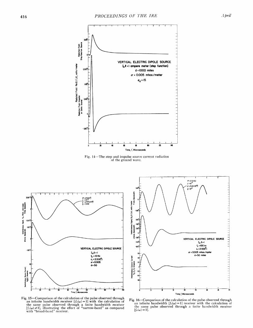
combinations of characteristic frequencyf =wc/27r anddampinig cl for both sine and cosine source functions areillustrated in Figs. 10-13 (pp. 414-415). The dispersion ofthe pulse at great distance is evident in the illustrationis.The most noteworthy attribute of this dispersion was aniincrease in the natural period of the pulse or a stretchingof the pulse in the time domain. The propagation me-dium thus illustrated, assuming a perfect (infinitebandwidth) receiver fr(w) = 1 filters the signal, andindeed at the greater distances the exact form of thesource becomes obscured by the filtering action.The cosine source (Figs. 11 and 13) employs an
abrupt initial current. The radiated field therefore prop-agated an impulse type of function which is superposedupon the sinusoid. This can be explained quite simplyfor the case of an infinitely conducting earth with the
where s =iw. The inverse Laplace tranisform £-C is
E(t', d) = £''E(s) = (t)
where the Dirac impulse funlctioln 6(t') can be definied inrelation to the step funictioin u(t); thus,
rtb()dt =(t),
,,j
(52)
where
u(t)=1, I>0
u(t) =O t < 0. (53)
The impulse is, of course, finiite in the danmped cosinewave (amplitude and durationi finlite) as a result of thefinite conductivity of the ground, the displacement cur-
rents in the ground and the effect of the earth's curva-
ture. The transient response of the ground wave atgreat distances illustrates (Figs. 12-14, pp. 415-416) thestretching of such pulses in the time domain.
The finiite bandwidth of a radio receiver or filter,(50°) fr(°) #;£ 1, cani be introduced by a mutilation of the Fou-
rier transform with onie or more frequency selective niet-works. Perhaps the simplest nietwork is the followinig
f ,1\series network:
R
I(ico)
fr(co) - R I
-co2 +- (iw) + -L C'L
(54)
where R is a resistive elemnenit (ohms) L is an iniductiveelement (henry) and C is a capacitive element (farads).The n1odificationi of the pulse by the finite bandwidthso described (54) for particular values of R, L anid C is
illustrated in Figs. 15 anid 16, p. 416). The ringinig of thecircuit becomes evident (Fig. 16) as the constants R, Land C are changed so that the bandwidth becomes quitenarrow, i.e., the Fourier spectrumii wave, fJ0(w, d) is ap-proached asymptotically.The damped sine-squared pulse, of which the enive-
lope shape, defined by sinil w, can serve as a useful nmodelfor the type pulse employed in radio navigation sys-
tems. Such a pulse can be syiothesized quite simiply byredefining the source funiction F,(t), (41), (42),
Fig. 12-IInstantaneous signal and correspondinig damped VLF sinewave source current of a propagated ground wave pulse.
Re F0(t) = exp (-cit) sin2 o.,t sin w,tRe F,(t) = 1 exp (- cit) sincot
-_ exp (-c1t) sin (w, + 2cow)t-4 exp (-cit) sin (wc - 2co)t.
(55)
(56)i i
Fs(t) = - exp (-Pt)- - exp (vpt)2 4
--exp (-V2t), (57)4
where
= cl + iwc (as before)
Vo = C1 + i(w, + 2wo)
P2 = C1 + i(cw,- 2p).
The typical radio navigation type pulse has a valuefor cl of the order of cop. It is quite obvious, however, thatthe amplitude time function E(t', d) for the dampedsine-squared pulse is merely the sum of three waves
Fig. 13-Instantaneous signal and corresponding damped VLF cosinewave source current of a propagated ground wave pulse illustrat-ing the introduction of a less abrupt initial source current.
where A i = i/2, A2 =-i/4, A3 =-i/4. A particularsine-squared pulse Re E(t', d) is illustrated in Fig. 17(p. 417) together with the amplitude envelope E(t', d) |.The source functions which represent natural phe-
nomena, such as sferics (the electromagnetic radiationfrom thunderstorms), will not, in general, have the pre-
cise mathematical form of a damped sinusoid, impulsefunction or step function. Since the application of thesuperposition principle is not always practical, anotherapproach to the general problem is appropriate [23],[25]. Indeed, it is quite possible to extend the theory tocomplicated waveforms. Consider an experiment inwhich the signal Re E(t', d) is observed and recordedat some distance d, from the source. The theory is thenrequired to predict the form of the signal recorded atsome other distance d2. The theory is also required todetermine the form of the source F8(t).
VERTICAL ELECTRIC DIPOLE SOURCEI I l-I aTr e-meter; fc - 17kc
Fig. 14 The step and imiipulse source currenit radiationof the ground wave.
Fig. 15-Comparison of the calculation of the pulse observed throughan infinite bandwidth receiver (fr(@) = 11 with the calculation ofthe same pulse observed through a finite bandwidth receiverLfr(c") illustratinig the effect of "narrow-band" as comparedwith "broad-balnd" receiver.
Time, t'Microseconds
Fig. 16-Comparison of the calculation of the pulse observed throughan infinite bandwidth [fr(w) = 11 receiver with the calculation ofthe same pulse observed through a finite bandwidth receiverIfr(,co) = 1.
-1
A pril416
Johler: Propagation of Low-Frequency Signal
cr
n
-l-i
a:
LDn-
cr
t (psec)
Fig. 17-The damped sine-squared pulse, illustrating synthesis of a
radio-navigationi system-type pulse with corresponding amplitudeenvelope.
The complex spectrum (48), (49) can be determineddirectly from the observed signal Re E(t', d):
rXfM(w, d) = exp (-iwt') Re E(t', d)dt'. (59)
The complex spectrum of the source fx,8(wo) can then bedetermined
fMw, d)(0
= E(w,d) (60)
Since the real part of the signal Re E(t', d) was em-
ployed, the source function Re F8(t). can be described
ex
F,(t) = exp (x)z8Xdo21r co
or
1 0x
F (t) =- f.a(W) I{cos [wt + x,a(cw)] I d@o, (62)7ro
Thus, with the aid of quadrature techniques [24], [26],the analysis of the detail of transient signals could becontinued ad infinitum.
V. IONOSPHERIC WAVES
The essential nature of the propagation of the iono-spheric waves is described by the four reflection coeffi-cients (36), (37) Tee, Tem Trrmmn Tine. These reflection co-efficients can be employed in VLF mode calculations ina method developed by Wait [26]. These reflection co-efficients have been employed directly in geomnetric-optical calculations [12 ]. In the latter the angle of inci-dence Xi is real. In either case a form of polarizationicoupling between vertically anid horizonitally polarizedwaves external to the ionosphere canl be noted. This ismost obvious in the calculation of the effective reflectioncoefficient of the geometric-optical theory Cj (Fig. 4).Notice that each reflection from the ionosphere gives riseto both horizontal and vertical polarization as a conise-quence of the generation of the abnormal componenit,in spite of the fact that the incident wave comprisespure vertical or horizontal polarization. Thus, the ab-normal component cannot be ignored in the case of ver-tically polarized transmitter and receiver for the or-dered propagation rays, j> 1, i.e., j= 2, 3, 4, . Thisis a form of coupling between wave polarizations quitedistinct from the coupling between the magneto-ionicpropagation components within the ionosphere to bedescribed subsequently.The evaluation of the reflection and transmission
processes at the ionosphere is the most complicated partof the problem of describing the transform of the signalEj(co, d) for any individual time-ordered ionosphericpropagation rayj= 1, 2, 3, . . The index of refractionof the ionosphere is first determined. The lower bound-ary of a model electron-ion plasma (Fig. 5) below which(z <0) the ionization is nil (N= O) or zero electrondensity, is considered to be the xy plane. The regionabove the xy plane (z > 0) is characterized by an electrondensity N and a collision frequency v which vary withrespect to altitude z. A plane wave Ei gives
Ei = |IiI exp [iwt D(61)
(65)
where the index of refraction (z<0), i7 =t7o = 1, c is thespeed of light c-3(108) m/sec and the quantity D is re-
lated to other parameters (Fig. 5) [19 ], [ 20 ], [ 27 ].
D = x sin 4i sin 4a+ y sin4i cos4a + z cs 9i, (66)
t'(fL sec)
- IFs(t)I,THE AMPLITUDE ENVELOPE OF THE SOURCE
Re Fs(t), THE SOURCE CURRENT MOMENT
1962 417
PROCEEDINGS OF T'HE IRE
is varying harmonicallv in tinmie t at a frequency f=w/2wranid is assumed to be incident upon the xy plane at anaingle of inicidence q5i and a miagnetic azimuth 0,, is meas-ured clockwise fromii the yz planie for the directioni ofpropagationi. The earth's imaginetic field vector I,,,ampere-turns/nmeter is cointained in the yz plaine at adip or inclin-ationi anigle I (miieasured from the hori-zontal).A resultanit wave Et transmitted inito the ionosphere
miiodel (z>O) (Figs. 5 and 18) is thein assumed to havethe formn
Et- |' It exp i ct --ID (67)
where, in the plasma mi,odel,= x sin. sin. 0, + ysin4icos4, + zs (68)
in which v is, in general, a complex number, the value ofwhich will depenid upoIn altitude z, ¢-=(z).The quantity ¢ is determined by a simnultaneous solu-
tion of Maxwell's equations
aHtV X F + Lot
(t= 0,
VX - f- -o--= °' (69)at
and the equation of motioni of ain electroIn (Laingevinlequation)
dV -m-+ mgV+ lioe(VX Hm)+ eE = 0 (70)
dt
with the electric field E, the magnetic field H7 (electro-dynamic as distiniguished from I7.. the static field of theearth), the convection currenit J= -NeV for N elec-
trolns per cubic meter (usually expressed as electronis/cc)withl charge e, mass m, aind vector velocity V, where IA(anid e0 are the permneability aind pernittivity of space,respectively. The collisioin frequenicy faictor g is as-sumed to be a con-staint real iiumliber with respect tofrequency; g--p is the classical miiagineto-ioiiic theory.
After elimiinlatinig the vectors V anid h, it can be coni-cluded that field E exists iii the miiediuLmi if ct qal(jrticequation in , is satisfied [I 1, [ 19 ], [20 ], [ 28 1,
aU4~4 + a3,3 + a2t2 + ajt + (a0 = 0 (71)
where the coefficienits of this quartic are definied in theAppenidix. The roots of this equationi ( ) are quitesimply related to the index of refractioni of the mniediuimiX or the wave nunmber k= (wlc)Pq, sitnce
'= -2 + Sin12 4t. (72)
The existeince of a quartic equationi in the inidex ofrefraction as a direct consequenice of the simiultanieotussolutioni of M\Iaxwell's equationis, (69) atnd the equationiof motioni of the electron (70) was first noted by Bookeranid the Booker quartic is more or less equivalenit to (71).Two pairs of roots ¢ canl be found [19] where eachi
root cani be identified as either ordinary or extraordi-nary, upgoinig or downigoinig mnagnieto-ionic propagat ioncomponent withini the mncodel ioniosphere plasim-a.
Sinice the electroni denisity and collisioni frequencycani vary with respect to altitude z, a mnodel plasmiawhich cani be deformed to fit miiost any- ineasured ortheoretical electroni-ioni profile, N(h), N(z), is desirablefromii the theoretical viewpoint to completely describethe reflectioni and transimissioni process at the ion-io-sphere. Several approaches to this problem have beeniutilized by various authors such as Buddeii 16] and Bar-roni [7]. The nlotioIn of a continuously varyinig mediumi
- ORDINARY (o) MODE-EXTRAORDINARY (e) MODE H,
|fl UPGOING 0) AND DOWNGOINGWAVES ARE COUPLED AT EACH BOUNDARY
Fig. 18-Structure of the flexible plasma miiodel, illustrating ordinaryand extraordinary propagation components, coupled at the bound-aries. Each slab (z,, n= 1, 2, 3, * * , p) becomes smaller as thenumber of slabs (p) is increased, until a stable reflection is ob-tained. z is always infinite where each N= N, v = vn correspondsto median values of the intervals (Z,), respectively, of the par-ticular profile under investigation.
418 .gA pril
Johler: Propagation of Low- Frequency Signal
has beeni treated by approximating the medium withone or more slabs of uniform compositioni as exemplifiedby the works of Brekhovskikh [29], Hines [30], Ferraroand Gibbon [31 J. Such methods have been exploitedby Johler and Harper [27], and carried to the limit,such that the number of slabs p for each calculation de-pends upon the computation precision required and theparticular values of the electric and geometric pa-ranmeters.The detailed structture of such a flexible model is il-
lustrated in Fig. 18 as a stack of plasma slabs of arbi-trary thickness (but consistent with computation effi-ciency) zn except the topmost slab of thickness zp= co.The number of such slabs p is also quite flexible, sincethe notion is implied in such a model that the measuredelectron density-altitude, N(h) or N(z) profile, and col-lision frequency altitude, v(h) or v(z) profile, can be ap-proximated to any desired accuracy by decreasing znand increasing p simultaneously until a stable reflectionprocess is obtained.A constant electron density and collision frequency
with respect to altitude z is of course assumed for eachslab. A set of four roots -=v of (71) are found to existin each slab. Two of the roots will exhibit a negativeimaginary (Im ¢ negative) corresponding to an upgoingwave (+z direction, Figs. 5 and 18) and two of theseroots will correspond to a positive imaginary (Im rpositive) corresponding to a downgoing wave (-z direc-tion, Figs. 5 and 18). It is necessary to consider both up-going and downgoing waves in the analysis of either the
reflection or transmission process at the ioniosphere,except for the topmost slab, where only the upgoingwaves are considered.
It is necessary to distiniguish between the ordiniaryand extraordinary magneto-ionic componients of propa-gation for both the upgoing anid downgoing waves.This is accomplished by an examination of the form ofthe index of refraction function with respect to fre-quency and altitude (or electron density and collisionfrequenicy which varies with respect to altitude). Thus,the index of refractioni v [as defined by (71), (72) ] is de-tailed for each frequenicy and slab zn, 7 = 7n,. The upgoingordiniary and extraordinary 77)e and the downgoinigordinary and extraordinary 1,7),e function conitinuity isexamiined in detail as a function of frequency to deter-mine, if any, the crossover points of the functions foreach slab or electron density under consideration.The absolute distinction between ordinary and extraor-dinary magneto-ionic wave components [19], [27]remains quite arbitrary, but the analysis must be con-sistent between each slab and consistent within eachslab for upgoing anid downgoing waves.The reflection and transmission coefficients are de-
termined by the boundary conditions which express atthe boundary of each slab the principle of continuityof the tangential E and H and the normal H fields(Figs. 5 and 18) of the model plasma. These fields areequated immediately above and below each boundaryand after considerable ado, a matrix equation is ob-tained [27],
Fig. 19-Electron denisity-altitude [N(h) or V(z)] (quiescentand disturbed) profiles.
where the elements of the matrix a1,, . . . are defined inthe Appendix.The upgoing ordinary and extraordinary and the
downgoing ordinary and extraordinary magneto-ioniccomponents of propagation are coupled within the iono-sphere (Fig. 18) as a result of the introduction of theboundary conditions described in concise form in thenmatrix equationi (73). Thus, at the upper and lowerboundary of each slab, energy is transferred betweenthe four magneto-ionic components of propagationi[four roots of the quartic equation (71)]. This type ofcoupling is distinct from the coupling of the polarizationcomponents, external to the ionosphere described pre-
viously [beginning of Sectioni V-see also Fig. 4 and(36) ].The continuously stratified technique can be illus-
trated by evaluating reflections from an ionosphereinodel determined by actual measured profiles of elec-tron density (Fig. 19) and collision frequency (Fig. 20).A typical daytime-room profile N(h) presented by Way-nick [32] (Fig. 19) anid a corresponding disturbed pro-
file of Seddoni and Jackson [33], indicative of the in-tensity of ioniization during a local auroral zone ioino-sonde blackout, were selected for purposes of illustratingapplication of the described conitiniuous stratificationtechniques. The region of the ionosphere oni the lattercurve, below 1000 electrons/cc, was represented (dashedcurve, Fig. 19) with a Gaussian distribution [6],
N = Nniax exp [-(z - zrnax) /k'],
where the constanits N10ax, z.,I,., and k' were determinedbv the measuredl profile > 1000 electronis/cc. In par-
ticular, Nmax 26,000, Zm1a, = 85,000, k' 1.92 (108).The Nicolet/3 collision frequency [34], [35] was em-
ployed in this analysis. These collision frequencies are
applicable to the classical magneto-ionic theory employ-inlg the approximation g-v [27], [36] in the equation ofmotion of the electroni (70).
NICOLET / 3
^-+@ \ ~~~~~~~~NN3.081'1216 CST, 4 JULY 1957
st10 7 - \ \ \ CHURCHILL -
z19551 \
CROMPTNu et cl (19531
1l06 -PWE
1\(953)
14 I150 60 70 g0 90 100 110 120
ALTITUDE, h, KILOMETERS
Fig. 20 Collisioni frequency-altitude [v(h) or v(z)l profiles(Nicolet/3 was employed in calculations)).
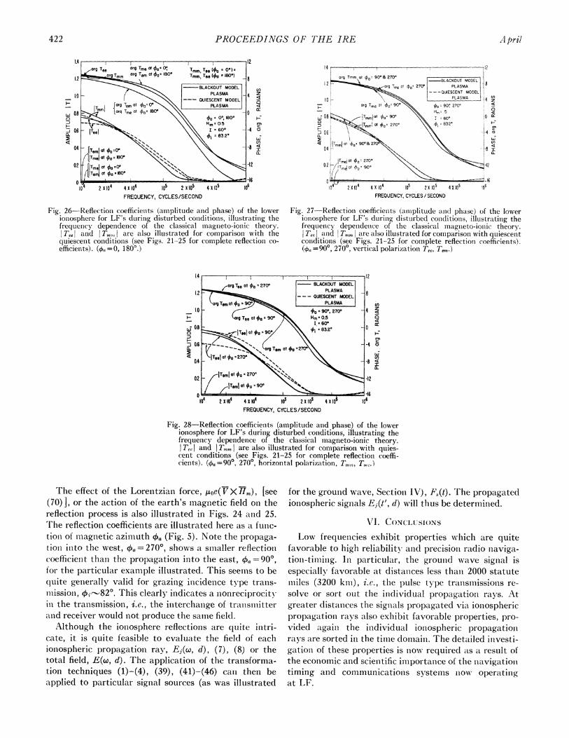
The reflection coefficients T'EE, 7',0, Tlh,, aiid Twnm wereevaluated (Figs. 21-28, pp. 421-422). The reflection co-efficients for the quiescent profiles are illustrated in Figs.19-25. The disturbed profiles reflection coefficienits areillustrated in Figs. 26-28.The reflection coefficients TC,1Cnj show a steadNy
decrease in amplitude as the frequency is inicreased. Asmall perceptible rise is nioted inear the gyrofrequency,however. This was a result of the approximnationig-v [27] and the assumed model, whereas the use of a
complex collision frequency g could exhibit higher at-tenuation niear the gyrofrequency. Such a complex col-lision frequenicy can be deduced from the work of Phelps[36], Molmlud [37], Janicel anid Kahani [38], where a
collisioin frequence vP=(u) proportional to the electronienergy or temperature is derived. Johler aniid Harper[27] have introduced electroni collisions proportionial toenergy as a modificationi of the coefficients of the quarticequation (71). This, of course, introduces somiie changesin the detail of the reflection coefficieints, but the generalformii of the reflection coefficients of the classical ihuag-neto-ionic theory remains unaltered at LF/VLF.
T'he miiagniitude of the abniormiial comiiponenits |en,I6 also shows a decrement as a funictioni of frequency.
These components are quite small for the assumiiedimiodel ( < 0.1 at 10 kc, for examnple). The correspondintgdisturbed blackout reflection coefficients imply a slightchatnge in the angle of inicideence Oi as a result of a lower-inig of the ionosphere. Ilowever, the principal cause ofchanige as a result of this profile is, nievertlheless, the re-distribution of the electron density-altitude profile. Itis iinterestinig to niote an inlcreased aIttellUation at thehigher frequencies 100 kc to 1000 kc. I-lowever, the hiighattenuation or total ionosonde blackout which char-acterizes high frequencies does iiot seemli to exist at LF.Indeed, an enhancement in the field is aniticipated fromthis profile at VLF ( < 30 kc).
.11 pril420
Johler: Propagation oj Low-Frequency Signal
4 X 0o 2X 10FREQUENCY, CYCLES/SECOND
F-
0-
421
cnz
a
i-
I-
Ut)
0.
Fig. 21-Reflection coefficients (amplitude and phase) of the lower Fig. 22 Reflection coefficients (amplitude and phase) of the lowerionosphere for LF's, illustrating the frequency dependence of the ionosphere for LF's, illustrating the frequencoy dependence of theclassical magneto-ionic theory (aO=0, 180°). ctassical magneto-ionic theory (4k, =90', 270 ), vertical polariza-
tion (Tee, Ter).
T-
Li
:3Q.
c / T,,,l at 0a -90
D4 4 4 0104 2 x 10 x 104 105 2X0
FREQUENCY, CYCLES /SECOND
Wz
i:
I-
a
LA;U)
0.
C)
-j-Ja.
4 X 10⁵ t0
Fig. 23-Reflection coefficients (amplitude and phase) of the lowerionosphere for LF's, illustrating the frequency dependence of theclassical magneto-ionic theory (+, =90', 2700), horizontal polari-zation (Tmni1, Tm.).
Fig. 24-Reflection coefficients (amplitude and phase) of the lowerionosphere for LF's, illustrating the action of the Lorentzian force(earth's magnetic field) in the classical magneto-ionic theory(f20 kc).
7
l-Teel v 4
z
4
rg Tem
-\ __ I
MAGNETIC AZIMUTH, O,, DEGREES
Fig. 25-Reflection coefficients (amplitude and phase) of the lowerionosphere for LF's, illustrating the action of the Lorentzian force(earth's magnetic field) in the classical magneto-ionic theory(f=100 kc).
1962
IA
1.2
_ 1.01-
a~4
0.4
02.i
PROCEEDINGS OF THE IRE
CO,z45
4Ce)a:
I0
H
w 0.80
-j
a.4
Q Peml at o, zO 1 \LIOTmeJ at fa 180= N<X'
02 fITmeOIat 00zAfTemi at Oa c e \
104 2 X 10⁴ 4 X le 105 2 x 10⁵FREQUENCY, CYCLES/SECOND
Fig. 26-Reflection coefficients (amiiplitude and phase) of the lowerionosphere for LF's during disturbed conditionis, illustratinig thefrequenicy dependence of the classical magneto-ionic theory.ITe,I and IT., are also illustrated for comparison with thequiescenit conditionis (see Figs. 21-25 for complete reflection co-efficients). ( 0=0, 180'.)
,,, 0.8
0.6a.
4
0.4-
i0
v104 2 X 10⁴ 4 X 10⁴ 105 2 X 10⁵ 4 X 10⁵FREQUENCY, CYCLES / SECOND
Fig. 27-Reflectioni coefficienits 'amiiplitude an(d phase) of the lowerionosphere for LF's during distuirbed conditionis, illustratinig thefrequency depenidence of the classical mageneto-ioniic theory.Tee and T,71,m are also illustrated for comparisoni with quiescent
conditions (see Figs. 21-25 for complete reflection coefficients).(g, =90', 270°, vertical polarization Tee, Tern)
I ~~~~~~~12BLACKOUT MODEL
PLASMA--- QUIESCENT MODEL 8
PLASMA
-goao 270 - 4 zHm*.5 cS
Ij- 60.2 l
O
0'2a270-\
\\ ~~w-8ro c-<
ma
4X10⁴ le 2XIO0FREQUENCY, CYCLES/SECOND
Fig. 28-Reflection coefficients (amplittide anid phase) of the lowerionosphere for LF's duiring disturbed conditions, illustratinlg thefrequency dependenice of the classical magneto-ionic theory.IT, and IT are also illustrated for comparisoin with quies-cent conditions (see Figs. 21-25 for complete reflectioni coeffi-cients). (0a =90°, 2700, horizonital polarization, T.,,T,,,Lic.)
The effect of the Lorentzian force, iA-oe(V> xH.), [see(70) , or the action of the earth's mnagnietic field oni thereflectioni process is also illustrated ill Figs. 24 and 25.The reflectioin coefficients are illustrated here as a func-tioni of mnagiietic azimuth q, (Fig. 5). Note the propaga-tioIn into the west, X =2700, shows a simaller reflectioncoefficienit than the propagation intto the east, b -=900,for the particular example illustrated. This seemiis to bequite genierally valid for grazinig inicideince type tratns-mllissioni, qi-82'. This clearly inidicates a nonreciprocityin the tranismission, i.e., the interchanige of transmitterand receiver would Inot produce the same field.
Although the ioniosphere reflections are quite initri-cate, it is quite feasible to evaluate the field of eaclhioniospheric propagation ray, Ej(w, d), (7), (8) or thetotal field, E(w, d). The applicationi of the transforma-tion techniques (1)-(4), (39), (41)-(46) catn then beapplied to particular signal sources (as was illustrated
for the grounid wave, Sectioni IV), F0,(t). The propagatedlioinospheric signals E1(t', d) will thus be determinied.
VI'l. CONCLUSIONSLow frequeincies exhibit properties whiclh are quite
favorable to high reliability anid precisionl radio naviga-tioni-timiinig. In particular, the grounid wave signal isespecially favorable at distanices less thani 2000 statuteiiiiles (3200 kin), i.e., the pulse type transmnissions re-
solve or sort oult the iiidividual propagation rays. Atgreater distanices the signials propagated via ioniosphericpropagation rays also exhibit favorable properties, pro-
vided againi the inidividual ioniospheric propagationrays are sorted in the timiie domiiaini. The detailed investi-gationi of these properties is ioNo required cas a result of
the economic anid scientific importance of the tnavigatiolntiming and communicationis systemns nowt operatingat LF.
422 A pril
iI,4 z
0
40P
J,-1-4 O! X
cn
-B I
z; 16106
Johler: Propagation of Low-Frequency Signal
APPENDIX
The coefficients of the quartic equation (71) are
ao= (a 1)2[1- ]+ (a2 -1) + aL2AT2 s-1s2 - /12 s S2 - h2 S(S2 - h2) s(s2 h2)
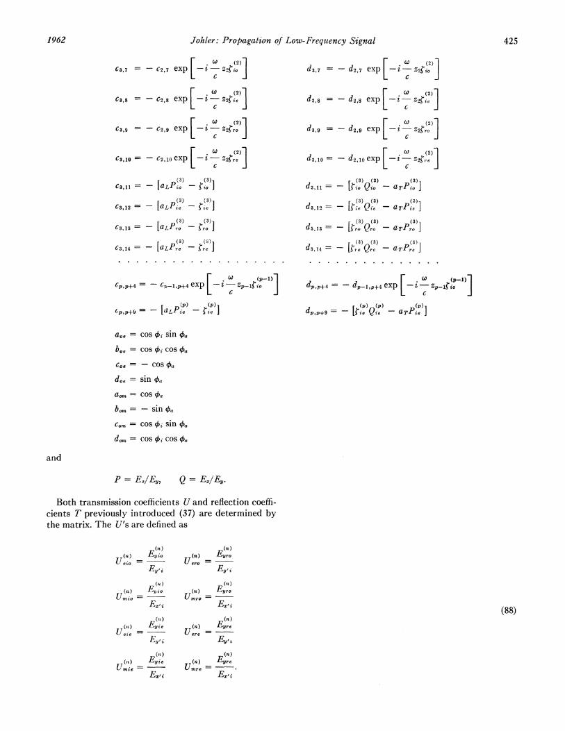
Both transmission coefficients U and reflection coeffi-cients T previously introduced (37) are determined bythe matrix. The U's are defined as
(n) (n)(n) Ebyio (n) Eyro
Ueio - Uero =Ey,,, Ey,
(n) (n)(n) Ejwo (t) ~Eyro
UMn io =Umro =
Ex'i E,zi (88)(n) (n)
(a1) Fyie (n) EyreUeie=i Uere = E
EF,j, Ey,(n) (n)
(it) ie (n) FyreUmrie - Urnre =
PROCEEDINGS OF THE IRE
The analytic expressions for the complex numberspo), p(),pI), pn), e Q(n) can be derivedfrom the definitions by a simultanieous solution of MVax-well's equation (69) and the equation of motion of theelectron (70) with the following result:
REFERENCES[1 H. Bremmer, "Terrestrial Radio Waves Theory of Propaga-
tion," Elsevier Publishing Co., New York, N. Y.; 1949.121 J. R. Wait, "Diffractioni theory for LF sky-wave propagatioll,"
J. Geophys. Res., vol. 66, 1713--- 730; Jtune, 1961.[31 G. Hefley, "Timing potenitials of Loran-C," Signal J. Armed
Forces Commun. and Electronics s.so(.. vwol. 15, pp. 45-47;Februarv, 1961.
aLr + ][t-haL)] _ ] + [aLaT - ][ -]
p=
[1 S211L2s2] []L2-[ ][_shTh
SlS2- 2 ]2-2_i - I/+IT2(S2 I2) 2 Il2 +(2h2]
s2 - hlL2-a2 -
S(S21 h2) __- aL2 -2 __
S2
[h7,- /I 1hh_ a T. + i a TD i
where the particular slab (Fig. 18) n = 1, 2, 3,p - 1, p under consideration is designated by the nota-tion ¢ (n)' p =p(n) Q= Q(n), and io, ie, ro, and re referto the four roots of the quartic in r for upgoing, down-going, ordinary, aiid extraordinary waves, respectively,in the particular part zn of the electroni-ion plasma underconsideration.The factor Fat r can be written [12]
F=t,r = (7)-'1/2 exp [-ik,a6']
{J0 exp [-i(kla/2)1/30"'a]
WT-i'(a) - qWI(c)
X exp [-i(kia12)"l30'a' - i2ir/3]da
- Wi'(a') qWi(a')
where oa' = a exp [-i2r/3] and
Wi(a') = -iV/r/3 (a)llH /3(2) ia32
IVf'(a') = \/ir/3 caH2/3(2) [2ia3/2a
where a is a positive real niumber.The following explicit form for the equation Fjtlr has
been suggested [39 ]:
F.; r = (X) -1/2 exp [-iktaO'lexp [-i(kia/2) 1/30'aJ]
da'5T 1 (a) - q If, i (a)
exp 2- -- (kla/2)1 '3Ola]
10 12'(a)- q exp [-i27r/3] W2(a) dax}where W2(a) and W2 (a) are airy integral functions ap-
propriate to the rotation a' = a exp (- 2iri/3).
[41 W. P. Frantz, W. N. Dean, and R. C. Frank, "A precisioin multi-purpose radio navigation system,'" 1957 IRE CONVENTIONRECORD, pt. 8, pp. 79-120.
[51 J. S. Belrose, W. L. Hattoni, C. A. MclKerrow, aind R. S. Thain,"The engineering of communicationi systems for low radio-frequencies," PROC. IRE, vol. 47, pp. 661-680; May, 1959.
[61 K. G. Budden, "The numerical solutioni of the differential equa-tionis governing the reflection of long radio waves from the iono-sphere, II,` Proc. Roy. Soc. (London) A, Phil. Trans., vol. 248,pp. 45-72; 1955-1956.
[71 D. W. Barron, "The numerical solutioii of differenitial equation'sgoverning the reflexion of long radio waves from the ionosphere,IV," Proc. Roy. Soc. (London), A, vol. 260, pp. 393-408: March,1961.
[8] H. Hertz, "Die Krafte Elektrischer Schwingunigen Behnadeltnach der Maxwell' schen Theorie," Ann. Phys. Chem. (Leipzig),vol. 36, pp. 1-22; 1889.
[9] H. A. Lorenitz, "The Theory of Electronis and its Applicatiolns tothe Phenomena of Light and Radiant Heat," G. E. Stechert andCo., New York, N. Y.; 1906.
[10] A. Sommerfeld, "Uber die Fortpflainzung des Lichtes in Disper-gierenden Medien," Ann. Phys., vol. 44, pp. 177-302; October,1914.
[11] L. Brillouiii, "Uber die Fortpflanzunlg des Lichtes in Disper-gierenden Medien," Ann. Phys., vol. 44, pp. 203-240; October,1914.
[121 J. R. Johler, "On the analysis of LF ioniospheric radio propaga-tion phenomena," J. Res. NBS, vol. 65D, pp. 507-529; Septem-ber-October, 1961.
[13] J. R. Johler, W. J. Kellar, and L. C. Walters, "Phase of the LowRadiofrequency Ground Wave," U. S. Gov. Printinig Office,Washiington, D. C., NBS Circular 573; June, 1956.
[141 J. R. Wait, "Diffractive corrections to the geometrical opticsof low frequency propagation," in "Electromagnetic WavePropagation," Academic Press, Londoni, Eng.; 1960.
[151 J. R. Wait anid A. M. Conda, "Pattern of anl anitennia onctirved lossy suirface," IRE TRANS. oN ANTENNAS AND PROPA-GATION, vol. AP-6, pp. 348--359; October, 1958.
161 J. R. Johler, L. C. Walters, and C. M. Lilley, "L,ow-- and VeryLow-Radiofrequency Tables of Ground WVave Paramneters forthe Spherical Earth Theory: the Roots of Riccati's DifferentialEquation," U. S. Dept. of Commiierce, Office Tech. Services,Washiingtoin, 1). C., NBS TIech. Note No. 7, I-'B-151366; Febru-ary, 1959.
[171 H. H. Howe, "Note oni the solutioni of Riccati's differenitial equa-tion," J. Res. NBS, vol. 64B, pp. 95-97; April-JunLe, 1960.
118] L. C. \Valters and J. R. Johler, "On the diffraction of sphericalwaves in the viciniity of a sphere, "J. Res. NB3S, vol. 661), pp.101 106; January-February, 1962.
[191 J. R. Johler and L. C. Walters, "Onl the theory of reflection oflow- and very low-radiofrequeiicy waves fromi the ionosphere,'J. Res. NBS, vol. 64D, pp. 259-285; May-June, 1960.
[20] J. R. Johler, "Magneto-ionic propagation phenomena in low- anidvery low-radiofrequency waves reflected by the ionosphere,"J. Res. NBS, vol. 65D, pp. 53-65; January-February, 1961.
[211 J. R. Johler, "On LF ionospheric phenomena in radlio navigation
(89)
(90)
A pril426
Johler: Propagation of Low-Frequency Signal
systems," presented at Avionics Panel Meeting of the AdvisoryGroup of Aeronautical Res. Dev. (AGARD), Istanbul, Turkey;October 3-8, 1960 (to be published, Pergamon Press, 1961-62).
[221 J. R. Johler, "A Note on the Propagation of Certain LF PulsesUtilized in a Radio Navigation System," U. S. Dept. of Com-merce, Office of Iech. Services, Washington, D. C., NBS 'I'ech.Note No. 118, PB-161619; September, 1961.
[231 J. R. Johler and L. C. Walters, "Propagation of a grouind wavepulse around a finitely conducting spherical earth from a dampedsinusoidal source currenit," IRE TRANS. ON ANTENNAS ANDPROPAGATION, vol. AP-7, pp. 1-10; January, 1959.
1241 W. Furrv, "Tables of the M\odified Hankel Functions of OrderOne-Third and of their Derivatives," Harvard UJniversitv Press,Cambridge, Mass., 1945.
125] J. R. Johler and C. M. Lilley, "Ground conductivity determina-tions at low radiofrequencies by an analysis of the sferic sig-natures of thunderstorms," J. Geophys. Res., vol. 66, pp. 3233-3244; October, 1961.
[261 J. R. Wait, "Terrestrial propagation of VLF radio waves," J.Res. N1BS, vol. 64D, pp. 153-204; March-April, 1960.
[271 J. R. Johler and J. D. Harper, Jr., "Reflection and transmissionof radio waves at a continuously stratified plasma with arbitrarymagnetic induction," J. Res. NBS, vol. 66D, pp. 81-99; Janu-ary-February, 1962.
[281 A. G. Booker, "Some general properties of the formulas of themagnetic-ionic theory," Proc. Roy. Soc. (London), A, vol. 147,p. 352: November, 1934.
[291 L. M. Brekhovskikh, "Waves in Layered Media," AcademicPress, Inc., New York, N. Y.; 1960.
[30] C. 0. Hines, "Wave packets, the Poynting vector and energyflow, pts. I-IV," J. Geophys. Res., vol. 56, pp. 63-72, March;pp. 197-220, JUne; pp. 535-544, December, 1951.
[311 A. J. Ferraro anid J. J. Gibbons, "Polarization compuitations bymeans of multislab approximation," J. Atmospheric and Terrest.Phys., vol. 16, pp. 136-144; October, 1959.
[32] A. H. 'aynick, "The present state of knowledge concernilng thelower ionosphere," PROC. IRE, vol. 45, pp. 741-749; June, 1957.
[331 J. C. Seddon and J. E. Jackson, "Rocket Arctic IonosphericMeasuremenits," Internati. Geophys. Soc., IGY Rocket Rept.Ser., No. 1, pp. 140-148; 1958.
[341 M. Nicolet, "Aeronomic Conditions in the Mesosphere andLower Ionosphere," Pennsylvania State Univ., UJniversity Park,Sci. Rept. No. 102; 1958.
[351 J. R. Johler and J. D. Harper, Jr., "On the Effect of a Solar Dis-turbance on the LF Ionosphere Reflection Process," presented at6th AGARD Ionospheric Res. Committee Meeting, Naples,Italy; May 15-18, 1961. "On Effects of Disturbances of SolarOrigin on Communications" (to be published, AGARDO-GRAPH, Pergamon Press).
[36] A. V. Phelps, "Propagation constants for electromagnetic wavesin weakly ionized, dry air," J. Appl. Phys. vol. 21, pp. 1723-1729; October, 1960.
[371 P. Molmud, "Langevin equation and the ac conductivity of non-Maxwellian plasmas," J. Phys. Res., vol. 114, pp. 29-32; April,1959.
[38] R. Jancel and T. Kahan, "Theorie du Complage des OndesErectromagnetiques Ordinaire et Extraordinaire dans un PlasmaInhomogene et Anisotrope et Conditions de Reflection," J.Phys. et Radian, vol. 15, pp. 136-145; 1955.
1391 J. R. Wait, private comm;-unicationi, November, 1960.
ADDITIONAL REFERENCESK. G. Budden, "Radio Waves in the Ionosphere," Cambridge Uni-
versity Press, London, England; 1961.J. A. Ratcliffe, "Physics of the Upper Atmosphere," Academic Press,
London, England; 1960.J. A. Ratcliffe, "Magneto-Ionic Theory and its Applications to the
Ionosphere," Camlbridge University Press, London, England; 1959.
A SHORT BIBLIOGRAPHY ON GROUNDWAVE PULSES
L. Brillouin, Uber die Fortpflanzunig des Lichtes in DispergierenidenMedien," Ann. Phys., vol. 44, pp. 203-240; 1914.
J. R. Johler, "Propagation of the Radiofrequency Ground WaveTransient over a Finitely Conducting Plane Earth," Geofis. pura eappl., vol. 37, p. 116; February, 1957.
J. R. Johler, "Transient radiofrequency ground waves over the sur-face of a finitely conducting plane earth," J. Res. NBS, vol. 60, p.281, April, 1958.
J. R. Johler, "A Note on the Propagation of Certain LF Pulses Uti-lized in a Radio Navigation System," U. S. Dept. of Commerce,Office of ech. Services, Washington, D. C., NBS Tech. Note No.118 PB 161619; October, 1961.
J. R. Johler and L. C. Walters, "Propagation of a ground wave pulsearound a finitely conducting spherical earth from a damped sinu-soidal source current," IRE TRANS. ON ANTENNAS AND PROPAGA-TION, vol. AP-7, pp. 1-11; January, 1959.
J. Keilson and R. V. Row, "Transfer of transient electromagneticwaves into a lossy medium," J. Appl. Phys., vol. 30, p. 1595;October, 1959.
B. R. Levy and J. B. Keller, "Propagation of electromagnetic pulsesarounid the earth," IRE TRANS. ON ANTENNAS AND PROPAGATION,vol. AP-6, p. 56-65; January, 1958.
V. V. Novikov, "Propagation of a radio pulse over the surface of aplane homogeneotus earth," Vestnik Leningrad. Uriv., Ser. Fiz. iKhim., Nrlo (Issue 2), p. 16; 1960.
V. V. Novikov and G. I. Makarov, "The propagation of pulse signalsover a plane homogeneous earth," Radiotech. Electron., vol. 5, p.708; April, 1961.
C. L. Pekeris and Z. Altermann, "Radiation from an impulsive ctur-rent in a vertical antenna placed on a dielectric ground," J. Appl.Phys., vol. 28, p. 1317; November, 1957.
A. Sommerfeld, "Uber die Fortpflanzung des Lichtes in Dispergie-renden Median," Ann. Phys., vol. 44, pp. 177-302; October, 1914.
B. van der Pol, "On discontinuous electromagnetic waves and the oc-currence of a surface wave," IRE TRANS. ON ANTENNAS AND PROP-AGATION, vol. AP-4, pp. 288-293; July, 1956.
J. R. Wait, "A note on the propagation of the transient ground wave,"Canad. J. Phys., vol. 35, p. 1146; September, 1957.
J. R. Wait, "Propagation of a pulse across a coastline," PROC. IRE(Correspondence), vol. 45, pp. 1550-1551; November, 1957.
J. R. Wait, "The transient behaviour of the electromagnetic groundwave over a spherical earth," IRE TRANS. ON ANTENNAS ANDPROPAGATION, vol. AP-5, pp. 198-205; April, 1957.
J. R. Wait, "Transient fields of a vertical dipole over homogeneouscurved ground," Canad. J. Phys., vol. 34, p. 116; January, 1956.
J. R. Wait, "On the waveform of a radio atmospheric at short ranges,"PROC. IRE (Correspondence), vol. 44, p. 1052; August, 1956.