1 Presenter: Narasimha Rao (Narsi), MP2 Subsurface Team Lead & WRFM Production Technologist Shell Philippines Shell Philippines Exploration B.V. Propellant Perforation for a Depleted Carbonate Subsea Gas Well – Malampaya Middle East & North Africa Perforation Symposium 3 rd – 4 th Dec 2013 , Muscat, Oman
Transcript
1
Presenter: Narasimha Rao (Narsi),
MP2 Subsurface Team Lead &
WRFM Production Technologist
Shell Philippines
Shell Philippines Exploration B.V.
Propellant Perforation for a Depleted Carbonate Subsea Gas Well – Malampaya Middle East & North Africa Perforation Symposium 3rd – 4th Dec 2013 , Muscat, Oman
2
Co-Authors & Acknowledgement
Mark Brinsden, Shell
Jim Gilliat, Baker Hughes
Neil Harvey, Shell
Vikas Bhushan, Shell
Milind Bhagwat, Shell
Michael Tan, Shell
3
Agenda
Malampaya Asset - Overview
Malampaya Phase 2 Project – Overview
Well Performance: Expected vs. Actual
STIMGUN Selection
Process Safety Due Diligence
Modeling Studies – Static & Dynamic
Yard Visit
Connector Test
Operational Overview
Conclusions & Project Learning's
Overview
Malampaya Asset
1.0
Malampaya Asset
5
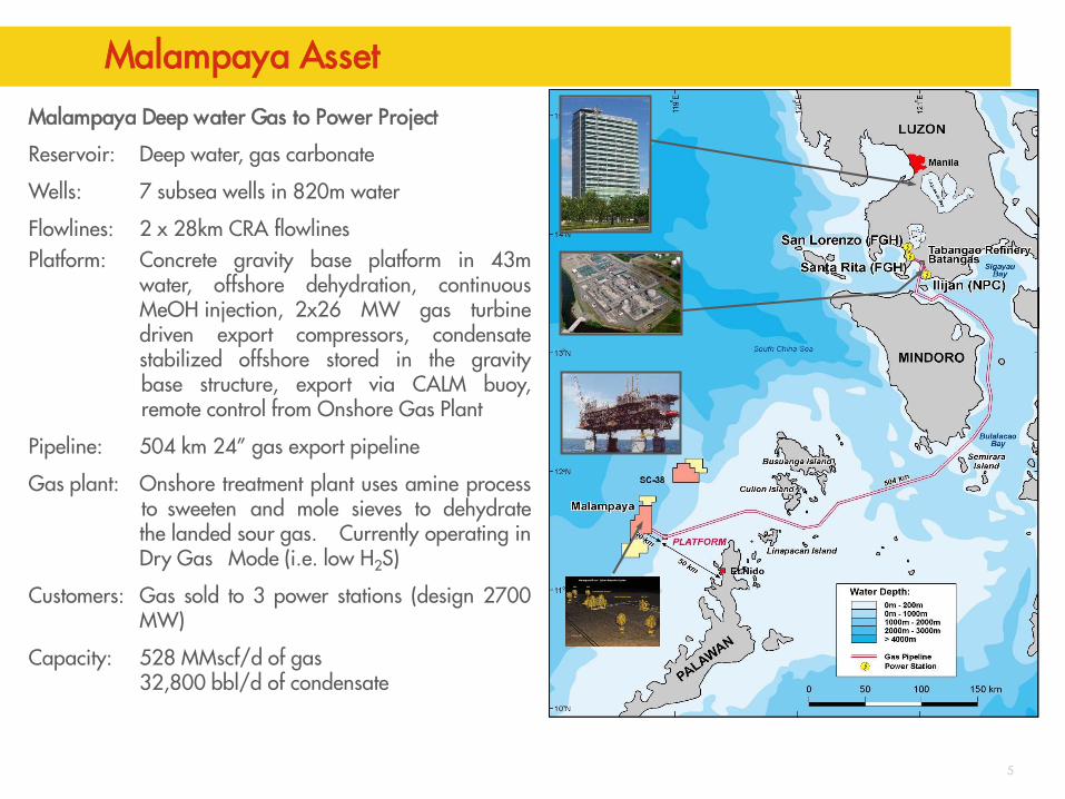
Malampaya Deep water Gas to Power Project
Reservoir: Deep water, gas carbonate
Wells: 7 subsea wells in 820m water
Flowlines: 2 x 28km CRA flowlines Platform: Concrete gravity base platform in 43m
water, offshore dehydration, continuous MeOH injection, 2x26 MW gas turbine driven export compressors, condensate stabilized offshore stored in the gravity base structure, export via CALM buoy, remote control from Onshore Gas Plant
Pipeline: 504 km 24” gas export pipeline
Gas plant: Onshore treatment plant uses amine process to sweeten and mole sieves to dehydrate the landed sour gas. Currently operating in Dry Gas Mode (i.e. low H2S)
Customers: Gas sold to 3 power stations (design 2700 MW)
Capacity: 528 MMscf/d of gas 32,800 bbl/d of condensate
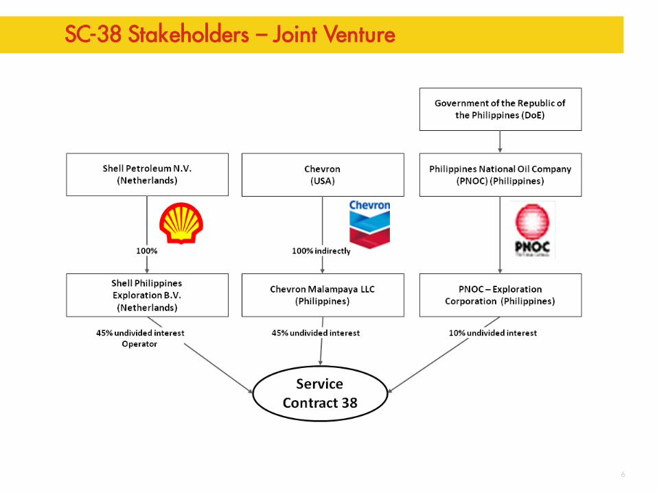
SC-38 Stakeholders – Joint Venture
6
Subsea to SWP to onshore…
7
MA-3
MA-9
MA-4
MA-6
MA-7 MA-5
MA-1
MA-8
MA-2
MA-10
CA-1
MA-11
MA-12
Malampaya – Camago Development
8
Discovery & Appraisal • Discovery: 1989, CA-1 (Occidental) • Gas Appraisal:1992-94, 4 MP wells • Oil Rim Appraisal 2002: MA-10
Development Phase 1 (MP1) • 5 MP wells & subsea production
system, Platform, pipeline and onshore gas plant (on-stream 2001)
Reservoir Pressure(closed -in BHP @centroid -3188.9 mtvdss and z-2phase corrected)
MA5 BHP
MA8 BHP
MA9 BHP
MA7 BHP
Pvirgin
2/3 Pvirgin
PDHG Pressure Readings from
three development
wells
Status Update
MP2 Overview
2.0
12
MA-11
MA-12
MP2 Spud Locations
5 Development Wells Each ~100 MMscf/day
13
Completion Schematic
Max. Deviation 49.1o
Design Life 20 yrs
Cased & Perforated
Long Liner Flow Design
7” Liner
9-5/8” Liner
Zero Intervention Philosophy
Thru Tubing Perforation
2” CT N2 for unloading if req
Stimulation: STIMGUN
Tubing: 7” X 9-5/8” X 7”
TR-SCSSSV 7”
Surveillance: PDHG
14
Gun Selection
200 m of perforation length per well
7” Liner Cased & Perforated Completion
3-3/8” OD STIMGUN was shortlisted
Min ID of Tubing hanger at subsea tree was 5.12”
Standard 6 SPF shot density, 60 deg phasing
Deep Penetrating HMX charges
Overview
Well Performance: Expected vs. Actual
3.0
LWD Reservoir Quality
Drilled reservoir section with total losses indicating a highly fractured carbonate as expected. Fractures observed on Image logs.
Reservoir quality more heterogeneous than the nearest offset well
High perm zones observed from log data.
Perforation interval optimized by lowering 15 m to connect to deeper high perm zones.
16
17
Well Testing Overview
Estimated 150 MMscf/day demonstrated
Clean up criteria achieved
Final Salinity 235 ppm and 0% BSW solids
~200 ft flare – Weather favourable
Dual Separator mode on the rig flowed to 120 MMscf/day (measured) - STABLE flow
Ensco 8504 DP Rig Well Testing ~ 200 ft flare
18
Expected IPR vs. Actual Flow Performance
Benefit of near well bore stimulation & thick high perm reservoir sections
P Res
STIMGUN Selection
4.0
20
Why did we need some form of Stimulation? Uncertainty Space -> Low Productivity -> Non-Deliverability
Reservoir Pressure depleted by 1/3rd from virgin pressure
Huge drilling & cementing losses expected
Presence of Karsts
Could expect thick damage zone around the wellbore that could go beyond depth of penetration offered by conventional perforations
Large uncertainty in (Permeability) Prognosis – Carbonates - Expect surprises!
Inefficient clean-up due to insufficient delta P or deeper invasion in high perm zones leading to a turbulent drainage pattern into the wellbore
Zero Intervention Philosophy - Well Completion Design
No interventions preferred for stimulation(acid jobs) in retrospect if wells do not flow at expected capacity
Insurance against non-deliverability of wells due to formation damage
100 MMSUD CAPEX per well
JV contributes to 40% of the Philippines Luzon Island’s power grid
21
What we needed?
Some near wellbore stimulation to by pass any potential damage zone
Not expecting new fracture generation as the reservoir was already fractured
Propellant loading could be kept modest to achieve this objective
22
Acid Jobs vs. Propellant Assisted Perforation
Complete stimulation of the reservoir section is very difficult to achieve using acid diversion techniques in a karstic environment due to the large variability in the permeability
Propellant-assisted perforating was considered as it achieves effective stimulation diversion equally across the entire perforated interval
Additionally, its usage eliminates the need for conventional, separate acid stimulation saving rig time and costs while reducing HS&E risks.
Overview
Due Diligence - MODELING for Malampaya Perforation Jobs
5.0
24
Perforation Modeling Objectives
Can the 1.75” CT work for MP2 wells or do we need 2” CT?
Do we need drag reducers or not?
Does it take all the loadings(static) in worst case scenario – fluid inside CT and gas in well after perforation ?
How does the system react under dynamic pressure conditions in worst case scenario – uncemented liner with all the cement lost to the formation?
What are the differential pressures expected across the packer and liner hanger in an Uncemented Liner scenario?
Any coil collapse risks?
Overview
COIL MODELING for Malampaya Wells
5.1
CIRCA Modeling – Static Loading – Coil Modeling Result
CERBERUS Coil modeling for Well: In-house by Shell, Miri
In-house Coil modeling done for the higher inclination well apart from vendor’s modeling – No Static showstoppers( RIH/POOH) for 2” CT
Overview
PULSFRAC MODELING for Malampaya Wells
5.2
29
Biggest Uncertainty
Quality of cement behind the 7” liner
Model the Worst Case Scenario: Assume complete loss of cement to the depleted reservoir
PULSFRAC Modeling Results
30
StimGun is loaded at 30% coverage, burn is complete. There is no fracturing but a surge effect has reduced the initial skin from +4.2 to zero.
31
PULSFRAC Modeling Results
Lack of reservoir pressure means no fracturing.
There is no “push back” from the formation, therefore pressure does not build up in the wellbore.
30% coverage does not provide enough energy to promote fracturing.
This is a result of the formation pressure allowing the gas to feed into the reservoir rather than building up in the wellbore.
Pressure Differentials across Packer & Liner Hanger
32
Personal checks
Labuan Yard Visit
5.3
34
Vendor Yard, Labuan, Malaysia
3-3/8” gun carriers
35
Vendor Yard, Labuan, Malaysia
3-3/8” gun & charge carriers
36
Vendor Yard, Labuan, Malaysia
Propellant sleeve
37
Vendor Yard, Labuan, Malaysia
Baker
Connector Pull out Test
5.4
39
Connector Pull-out Test
Sarawak well had a CT Connector failure in 2007 during a STIMGUN Job
Gun movement kick on the connector presents a dynamic load.
CT connector could be the weakest link and could fail before the coiled tubing.
Static load limit from coil modeling not acceptable.
To find out the pull out force from Coil Tubing Connector from vendor
2.88” OD Grapple Connector was used
Conducted in December 2012 in Houston at vendor’s facility
New 2” Tapered CTU ( wall thickness 0.156” to 0.125” ) used – which was planned for MP2 jobs
40
Connector Pull-out Test
Conclusion: 2” Coil (which we used) was weak point. 2.88” CT connector passed the test.
Learning From Incident LFI-PTW-I-D-201304
Operational Overview
6.0
42
MP2 Perforation Jobs - Overview
All charges on all guns fired on visual inspection.
No H2S content reported on gun POOH.
Wells unloaded completely to gas in less than 24 hrs without any need for N2 lifting via CT (back up Well Unloading Plan).
Malampaya Well Test separators were opened in Labuan and found no debris at all. Confirms that the propellant was completely burnt.
Fast Downhole Gauges were used at bottom of perforation gun successfully in both the wells to collect high frequency pressure and temperature data and the data was recovered for Post Job PULSFRAC Analysis.
On one of the wells- Dropped Incident 70 kg dropped 10 m to rig floor.
43
Dropped Object
44
Dropped Object Incident
Occurred in the process of making up the Telecoil/firing head assembly onto the deployed TCP gun assembly
Firing assembly released at an ‘A2’ Wireline connector and dropped 10 m to the rig floor.
Weighed 70 kg and measured 2.2 m X 3.375”
Drop event was in a controlled “RED” zone, which was barriered off
Luckily, no crew was in the “RED” zone.
45
Why it happened?
‘A2’ wireline connector was used in the firing head assembly
Torque by hand and has no form of secondary lock mechanism
Wireline connector typically used in a TCP toolstring
Removing the protector introduced left-hand rotation into the assembly which resulted in the ‘A2’ connection backing off
Assembly was inside the CT BOP and riser
The reason for the wireline connection was related to the Tele-coil being included in the BHA, which is an unusual application for the vendor and hence different product groups of vendor working together to make a workable BHA: wireline (for the telecoil), CT, TCP and the telecoil group.
Interface management between different groups of vendor needed more focus
46
Lessons Learnt
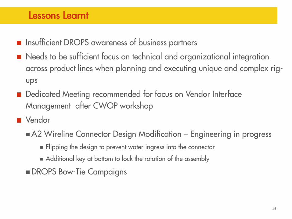
Insufficient DROPS awareness of business partners
Needs to be sufficient focus on technical and organizational integration across product lines when planning and executing unique and complex rig-ups
Dedicated Meeting recommended for focus on Vendor Interface Management after CWOP workshop
Vendor
A2 Wireline Connector Design Modification – Engineering in progress Flipping the design to prevent water ingress into the connector
Additional key at bottom to lock the rotation of the assembly
DROPS Bow-Tie Campaigns
47
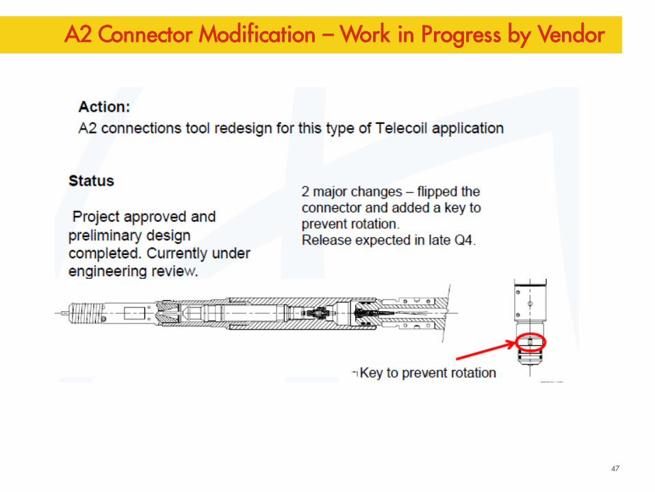
A2 Connector Modification – Work in Progress by Vendor
48
Conclusions
Stimulation was deemed necessary for Malampaya wells given the depleted reservoir and total losses scenario expected – 1 MM USD as insurance for 200 MM USD Subsea campaign for both wells
STIMGUN was selected based on optimization of rig time, ineffectiveness of acid jobs in a karstified, fractured carbonate and Process Safety considerations
2” CT collapse risk mitigation
Moderate propellant loading to 30%
Overbalance Perforation preferred to make system stiffer
Seawater + MEG mixture inside and outside coil(for hydrate prevention)
N2 lift contingency as well unloading plan if need be
200 m Perforation guns perforated successfully with 30% propellant loading
Better inflow performance than expected: Benefit of near well bore stimulation & thick high perm reservoir sections
49
Malampaya Perforation Design - Project Learning’s
Always work very closely with vendor and do not assume
Get PTE/SME steer early into the Project to ensure all risks are completely assessed
Static conditions modeling is not adequate – CIRCA, Cerebrus models
Detailed dynamic analysis of actual BHA(Perforation) should be modeled including the accurate spacer lengths, blank section to assess the impact of pressure surges/dynamic UB
PULSFRAC Modeling: Always update the models after drilling the reservoir section with actual LWD based reservoir quality info to see how the dynamic perforation wave impacts the bottom hole assembly and completion components and how much energy gets absorbed by the formation
50
Malampaya Perforation Design - Project Learning’s
Check for differential pressures across packer and liner hanger components
12.8m spacer sub chosen for MP2 wells to ensure Top Shot below the Rotary for Operations Personnel Safety while RIH
Ensure proper MOC is followed and take vendors along in all the discussions
Time consuming Finite element modeling work in PULSFRAC
Frequent crashes of servers – take snapshots frequently when doing PULSFRAC
As a single operated asset in the Philippines, the operator Shell effectively leveraged on its global resources & expertise, e.g. global technology centers in India, Europe and US, and operations teams in the region. A degree of collaborative virtual working is essential for success in today’s world.