Properties and failure mechanisms of pinned composite lap joints in monotonic and cyclic tension P. Chang a , A.P. Mouritz a, * , B.N. Cox b a School of Aerospace, Mechanical and Manufacturing Engineering, RMIT University, GPO Box 2476V, Melbourne, Victoria 3001, Australia b Rockwell Scientific Co. LLC, 1049 Camino Dos Rios, Thousand Oaks, CA 91360, USA Received 9 May 2005; received in revised form 8 November 2005; accepted 22 November 2005 Available online 28 February 2006 Abstract The effect of through-thickness reinforcement by fibrous pins on the static tensile strength, fatigue life and failure mechanisms of sin- gle lap joints made of carbon/epoxy composite is investigated. Pinning is highly effective in increasing the ultimate strength, elongation limit and fatigue life. Improvements to the monotonic and fatigue properties are attributed to transitions in the failure mechanisms, from unstable joint debonding in the absence of pins to stable debonding in the presence of pins followed by ultimate failure by pin pull-out or shear fracture or tensile laminate rupture. Which mechanism induces ultimate failure in the presence of pins depends on their volume content and diameter. The trends with volume content and diameter can be predicted qualitatively using analytical results from a pre- viously published model of the deformation mechanics of pins loaded in mixed mode. Ó 2006 Elsevier Ltd. All rights reserved. Keywords: A. Polymer-matrix composites (PMCs); B. Mechanical properties; Joints; z-Pins 1. Introduction A long-standing concern with adhesively bonded and co-cured joints between fiber-reinforced polymer compos- ites is catastrophic failure of the bond-line due to over- loading, environmental degradation or fatigue. Bonded joints are particularly susceptible to delamination failure when subjected to in-plane tensile loading that imparts a shear stress along the bond-line. Composite lap joints can be strengthened in several ways, with the most common being the use of a high toughness adhesive at the bond-line in combination with reinforcement by mechanical fasteners (e.g., screws, bolts, rivets). However, machined fastener holes are stress concentration sites under tensile and shear loading that may cause local damage to the surrounding composite material. An alternative approach to improve the ultimate strength of joints is to reinforce the bonded region with stitches [1–9], rods or pins [10–18]. Stitching with high strength fibrous yarns through the overlap region of a joint improves both the tensile strength (up to 40%) and fatigue performance (up to two orders of magnitude) [6–9]. Stitch- ing does not suppress delamination cracking along the bond-line, however the unbroken stitches bridge the bond-line of a fractured joint and there sustain the applied stress across the joint to higher loads. The stitches are typ- ically 0.5–1 mm in diameter and therefore introduce a sig- nificant perturbation to the in-plane fibers. Inserting thin rods or pins through a composite can be a less costly and easier manufacturing process and allows metallic as well as composite materials to be used. The pos- sibility also exists of discovering processing methods for introducing much finer pins or rods, even down to nanome- ter dimensions, which may have significant performance benefits. However, current pinning techniques are restricted to pins of diameter 0.25 mm and greater. Pinning reinforcement has yielded large improvements in the shear 0266-3538/$ - see front matter Ó 2006 Elsevier Ltd. All rights reserved. doi:10.1016/j.compscitech.2005.11.039 * Corresponding author. Tel.: +61 3 9925 6269; fax: +61 3 9925 6108. E-mail address: [email protected](A.P. Mouritz). www.elsevier.com/locate/compscitech Composites Science and Technology 66 (2006) 2163–2176 COMPOSITES SCIENCE AND TECHNOLOGY
Transcript
COMPOSITES
www.elsevier.com/locate/compscitech
Composites Science and Technology 66 (2006) 2163–2176
SCIENCE ANDTECHNOLOGY
Properties and failure mechanisms of pinned composite lap jointsin monotonic and cyclic tension
P. Chang a, A.P. Mouritz a,*, B.N. Cox b
a School of Aerospace, Mechanical and Manufacturing Engineering, RMIT University, GPO Box 2476V, Melbourne, Victoria 3001, Australiab Rockwell Scientific Co. LLC, 1049 Camino Dos Rios, Thousand Oaks, CA 91360, USA
Received 9 May 2005; received in revised form 8 November 2005; accepted 22 November 2005Available online 28 February 2006
Abstract
The effect of through-thickness reinforcement by fibrous pins on the static tensile strength, fatigue life and failure mechanisms of sin-gle lap joints made of carbon/epoxy composite is investigated. Pinning is highly effective in increasing the ultimate strength, elongationlimit and fatigue life. Improvements to the monotonic and fatigue properties are attributed to transitions in the failure mechanisms, fromunstable joint debonding in the absence of pins to stable debonding in the presence of pins followed by ultimate failure by pin pull-out orshear fracture or tensile laminate rupture. Which mechanism induces ultimate failure in the presence of pins depends on their volumecontent and diameter. The trends with volume content and diameter can be predicted qualitatively using analytical results from a pre-viously published model of the deformation mechanics of pins loaded in mixed mode.� 2006 Elsevier Ltd. All rights reserved.
Keywords: A. Polymer-matrix composites (PMCs); B. Mechanical properties; Joints; z-Pins
1. Introduction
A long-standing concern with adhesively bonded andco-cured joints between fiber-reinforced polymer compos-ites is catastrophic failure of the bond-line due to over-loading, environmental degradation or fatigue. Bondedjoints are particularly susceptible to delamination failurewhen subjected to in-plane tensile loading that imparts ashear stress along the bond-line. Composite lap joints canbe strengthened in several ways, with the most commonbeing the use of a high toughness adhesive at the bond-linein combination with reinforcement by mechanical fasteners(e.g., screws, bolts, rivets). However, machined fastenerholes are stress concentration sites under tensile and shearloading that may cause local damage to the surroundingcomposite material.
0266-3538/$ - see front matter � 2006 Elsevier Ltd. All rights reserved.
An alternative approach to improve the ultimatestrength of joints is to reinforce the bonded region withstitches [1–9], rods or pins [10–18]. Stitching with highstrength fibrous yarns through the overlap region of a jointimproves both the tensile strength (up to 40%) and fatigueperformance (up to two orders of magnitude) [6–9]. Stitch-ing does not suppress delamination cracking along thebond-line, however the unbroken stitches bridge thebond-line of a fractured joint and there sustain the appliedstress across the joint to higher loads. The stitches are typ-ically 0.5–1 mm in diameter and therefore introduce a sig-nificant perturbation to the in-plane fibers.
Inserting thin rods or pins through a composite can be aless costly and easier manufacturing process and allowsmetallic as well as composite materials to be used. The pos-sibility also exists of discovering processing methods forintroducing much finer pins or rods, even down to nanome-ter dimensions, which may have significant performancebenefits. However, current pinning techniques arerestricted to pins of diameter 0.25 mm and greater. Pinningreinforcement has yielded large improvements in the shear
2164 P. Chang et al. / Composites Science and Technology 66 (2006) 2163–2176
strength of single lap joints [19,20], the pull-off strength ofT-joints [18], and the fatigue life of blade-stiffened panels[21]. For example, Rugg et al. [19] measured a doublingin the ultimate failure strength of a lap joint when rein-forced with pultruded carbon fiber pins. Freitas et al. [18]found that the pull-off strength of T-joints was improvedby 2.3–2.6 times with composite pins; although in a differ-ent study, Rugg et al. [22] found much more modestimprovements, between 0% and 40%, depending on thearm length in the loading configuration (which controlsthe fracture mode ratio and thus the failure mechanism).As with stitched joints, the ultimate strength is improveddue to a crack bridging mechanism in which pins transferthe applied stress across the joint after bond-line fracture.Bridging by pins has a profound effect on the propagationof large delamination cracks (longer than �5 mm), oftenleading to crack arrest due to shielding of the delaminationcrack tip from the applied load. Rugg et al. [19] and Cartieet al. [23] observed that both composite and metallic pinsintroduce several energy absorption processes, includinginelastic deformation, pull-out and/or fracture of the pins;and irreversible deformation of the surrounding compositematerial. These processes may increase energy absorptionof the joint 100 times over a simple adhesive joint [19].Improvements in ultimate strength of the joint are relatedto the strength of the pins and their resistance to beingpulled out of the laminate [24,25].
Despite the known benefits of pinning composite joints,the influence of the volume content and size of the pins onthe tensile strength and tensile fatigue life has not been sys-tematically investigated and optimum pinning conditionsremain to be established. Therefore, the aim of the presentstudy is to investigate the effects of the density and diame-ter of pins on the strength and fatigue life of co-cured car-bon/epoxy composite joints. A number of distinct failuremechanisms are observed, which can be accounted for bya recent model of pin deformation mechanics. A methodfor systematic optimisation of pinning will be sought fromthe experimental data and the model.
2. Materials and experimental techniques
2.1. Manufacture of z-pinned lap joints
Single lap joints were made using plain woven [0/90�]carbon/epoxy prepreg (Fiberdux 914).1 The prepreg waslaid up with the warp (0�) fibers aligned along the jointlength, which is also the direction of tensile loading. Priorto curing, the joints were pinned through the overlapregion using 8 mm long pultruded carbon/bismaleimidepins.2 The arms of the adherent outside the overlap regionwere not pinned. The pins were inserted in the through-thickness direction of the joint using a hand-held ultrason-
1 Supplied by Hexcel, Greenborough, Victoria, Australia.2 Z-FibersTM produced by Aztex Inc., Waltham, Massachusetts.
ically actuated horn in a process described by Freitas et al.[17,18]. The tips of the pins are chamfered to an angle of45� to aid their penetration through the uncured prepregstack. The pins were embedded until they completely pen-etrated the overlap region. The pins protruded slightlyfrom the bottom surface of the joint, and the protrusionswere carefully abraded off using fine-grade abrasive paperwithout scratching the surface. The excess length of pinthat protruded from the upper surface of the joint wassheared off with a blade.
The influence of pin density was examined by reinforc-ing the lap joint with small (0.28 mm) diameter pins to areadensities of 0.5%, 2.0% and 4.0%. The pins are arranged ina square pattern with a spacing of 3.5 mm for the 0.5%,1.75 mm for 2.0% and 1.2 mm for 4.0%. The effect of pindiameter was examined by reinforcing the joint using small(0.28 mm) or large (0.51 mm) diameter pins to the samearea density of 2.0%. The large diameter pins are alsoarranged in a square pattern with a spacing of 3.2 mm.After pinning, the lap joints were consolidated and curedin an autoclave at an overpressure of 500 kPa and temper-ature of 115 �C for 1 h and then 750 kPa and 180 �C for2 h. Lap joints without pins were made as reference speci-mens, and cured under the same conditions as the pinnedsamples. The pinned and unpinned joints were bonded byco-curing of the laminate adherents in the autoclave; noadhesive film was used in the bond-line to increase the ulti-mate strength and toughness of the joints.
The nominal thickness of the overlap region wasintended to be 4 mm, but the insertion of the z-pins causedconsiderable thickening in this region (Table 1). Part of thethickness increase with pin content may be due to swellingof the prepreg stack to accommodate the pins. However,the percentage increase in thickness is much higher forthe present lap joints than in flat coupon specimens [25].In the flat coupons, the proportional increase in thicknesswas similar to the pin volume fraction. Table 1, in contrast,shows increases up to 20%. Microstructural examinationrevealed that the swelling was not accompanied by the for-mation of voids, porosity or other defects in the bondregion. The consolidation of the joint region under thepressure used during cure is therefore inferred to berestricted by the presence of the pins, which tend to propapart the faces of the tooling, resulting in a thicker bondedregion. Simple load transfer analysis shows that theincrease in total joint thickness will not significantly alterthe magnitude of the bond-line shear stress induced for agiven tensile load. Furthermore, since the bond-line (resin
P. Chang et al. / Composites Science and Technology 66 (2006) 2163–2176 2165
layer) thickness is not affected by the swelling, the criticallocal conditions for bond-line crack propagation shouldnot be affected by the swelling, since, for most of its prop-agation, the crack front is not intersecting a pin. (However,as discussed below, the far-field conditions for crack prop-agation will be considerably changed by pin bridging,through its shielding effect in the crack wake).
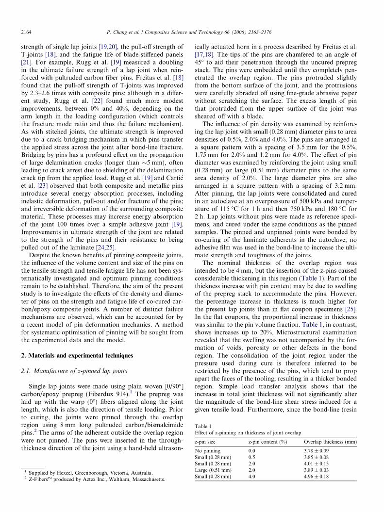
During insertion of the pins and subsequent consolida-tion of the lap joints during curing in the autoclave mostof the pins became misaligned. Fig. 2 shows a pinned lam-inate in cross-section. The pin is inclined at an off-set angle(/) from the orthogonal (through-thickness) direction.Detailed measurements of the off-set angle were reportedin Chang et al. [25] for pins inserted into a unidirectionalcarbon/epoxy tape laminate. The off-set angles for thesmall (0.28 mm) and large (0.51 mm) diameter pins were13.8 ± 4.2� and 23.4 ± 4.5�, respectively. Measurementsmade at different stages of processing revealed that mis-alignment occurred both when the excess pin length wassheared off with the blade and during compaction in theautoclave [25]. Similar off-set angles are expected for thewoven carbon/epoxy used in the lap joint specimens stud-ied in the present work.
Because of the misalignment, the areal fraction of pinson the plane of the bond-line in the joints was slightlygreater than had the pins remained orthogonal (Table 2).The offset causes a few percent increase in the area fraction,which will have no effect on the limited analysis presentedin the present paper.
2.2. Tensile and fatigue testing
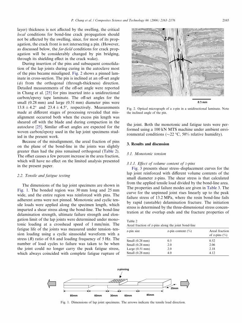
The dimensions of the lap joint specimens are shown inFig. 1. The bonded region was 30 mm long and 25 mmwide, and the entire region was reinforced with pins. Theadherent arms were not pinned. Monotonic and cyclic ten-sile loads were applied along the specimen length, whichimparted a shear stress along the bond-line. The bond-linedelamination strength, ultimate failure strength and elon-gation limit of the lap joints were determined under mono-tonic loading at a crosshead speed of 1 mm/min. Thefatigue life of the joints was measured under tension–ten-sion loading using a cyclic sinusoidal waveform with astress (R) ratio of 0.6 and loading frequency of 5 Hz. Thenumber of load cycles to failure was taken to be whenthe joint could no longer carry the peak fatigue stress,which always coincided with complete fatigue rupture of
85mm 60mm 30mm 6
z-pinni
Fig. 1. Dimensions of lap joint specimens. The
the joint. Both the monotonic and fatigue tests were per-formed using a 100 kN MTS machine under ambient envi-ronmental conditions (�22 �C, 50% relative humidity).
3. Results and discussion
3.1. Monotonic tension
3.1.1. Effect of volume content of z-pins
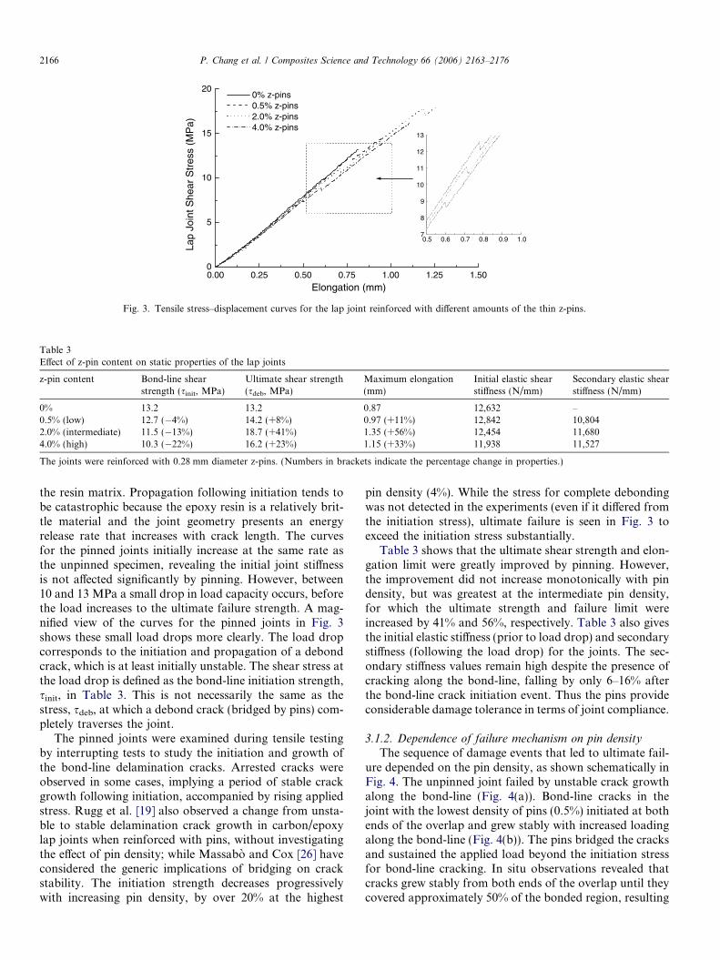
Fig. 3 presents shear stress–displacement curves for thelap joint reinforced with different volume contents of thesmall diameter z-pins. The shear stress is that calculatedfrom the applied tensile load divided by the bond-line area.The properties and failure modes are given in Table 3. Thecurve for the unpinned joint rises linearly up to the peakfailure stress of 13.2 MPa, where the resin bond-line failsby rapid (unstable) delamination fracture. The initiationstress is determined by the three-dimensional stress concen-tration at the overlap ends and the fracture properties of
0mm 85mm
25mm
ng
arrows indicate the tensile load direction.
0.00 0.25 0.50 0.75 1.00 1.25 1.500
5
10
15
20
0.5 0.6 0.7 0.8 0.9 1.07
8
9
10
11
12
13
0% z-pins 0.5% z-pins 2.0% z-pins 4.0% z-pins
Lap
Join
t She
ar S
tres
s (M
Pa)
Elongation (mm)
Fig. 3. Tensile stress–displacement curves for the lap joint reinforced with different amounts of the thin z-pins.
Table 3Effect of z-pin content on static properties of the lap joints
The joints were reinforced with 0.28 mm diameter z-pins. (Numbers in brackets indicate the percentage change in properties.)
2166 P. Chang et al. / Composites Science and Technology 66 (2006) 2163–2176
the resin matrix. Propagation following initiation tends tobe catastrophic because the epoxy resin is a relatively brit-tle material and the joint geometry presents an energyrelease rate that increases with crack length. The curvesfor the pinned joints initially increase at the same rate asthe unpinned specimen, revealing the initial joint stiffnessis not affected significantly by pinning. However, between10 and 13 MPa a small drop in load capacity occurs, beforethe load increases to the ultimate failure strength. A mag-nified view of the curves for the pinned joints in Fig. 3shows these small load drops more clearly. The load dropcorresponds to the initiation and propagation of a debondcrack, which is at least initially unstable. The shear stress atthe load drop is defined as the bond-line initiation strength,sinit, in Table 3. This is not necessarily the same as thestress, sdeb, at which a debond crack (bridged by pins) com-pletely traverses the joint.
The pinned joints were examined during tensile testingby interrupting tests to study the initiation and growth ofthe bond-line delamination cracks. Arrested cracks wereobserved in some cases, implying a period of stable crackgrowth following initiation, accompanied by rising appliedstress. Rugg et al. [19] also observed a change from unsta-ble to stable delamination crack growth in carbon/epoxylap joints when reinforced with pins, without investigatingthe effect of pin density; while Massabo and Cox [26] haveconsidered the generic implications of bridging on crackstability. The initiation strength decreases progressivelywith increasing pin density, by over 20% at the highest
pin density (4%). While the stress for complete debondingwas not detected in the experiments (even if it differed fromthe initiation stress), ultimate failure is seen in Fig. 3 toexceed the initiation stress substantially.
Table 3 shows that the ultimate shear strength and elon-gation limit were greatly improved by pinning. However,the improvement did not increase monotonically with pindensity, but was greatest at the intermediate pin density,for which the ultimate strength and failure limit wereincreased by 41% and 56%, respectively. Table 3 also givesthe initial elastic stiffness (prior to load drop) and secondarystiffness (following the load drop) for the joints. The sec-ondary stiffness values remain high despite the presence ofcracking along the bond-line, falling by only 6–16% afterthe bond-line crack initiation event. Thus the pins provideconsiderable damage tolerance in terms of joint compliance.
3.1.2. Dependence of failure mechanism on pin density
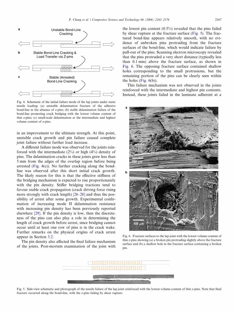
The sequence of damage events that led to ultimate fail-ure depended on the pin density, as shown schematically inFig. 4. The unpinned joint failed by unstable crack growthalong the bond-line (Fig. 4(a)). Bond-line cracks in thejoint with the lowest density of pins (0.5%) initiated at bothends of the overlap and grew stably with increased loadingalong the bond-line (Fig. 4(b)). The pins bridged the cracksand sustained the applied load beyond the initiation stressfor bond-line cracking. In situ observations revealed thatcracks grew stably from both ends of the overlap until theycovered approximately 50% of the bonded region, resulting
Unstable Bond-Line Cracking
Stable Bond-Line Cracking & Load Transfer via Z-pins
Stable (Arrested) Bond-Line Cracking
a
b
c
Fig. 4. Schematic of the initial failure mode of the lap joints under statictensile loading: (a) unstable delamination fracture of the adhesivebond-line in the absence of z-pins; (b) stable delamination failure of thebond-line promoting crack bridging with the lowest volume content ofthin z-pins; (c) small-scale delamination at the intermediate and highestvolume content of z-pins.
Fig. 6. Fracture surfaces to the lap joint with the lowest volume content ofthin z-pins showing (a) a broken pin protruding slightly above the fracturesurface and (b) a shallow hole in the fracture surface containing a brokenpin.
P. Chang et al. / Composites Science and Technology 66 (2006) 2163–2176 2167
in an improvement to the ultimate strength. At this point,unstable crack growth and pin failure caused completejoint failure without further load increase.
A different failure mode was observed for the joints rein-forced with the intermediate (2%) or high (4%) density ofpins. The delamination cracks in these joints grew less than5 mm from the edges of the overlap region before beingarrested (Fig. 4(c)). No further cracking along the bond-line was observed after this short initial crack growth.The likely reason for this is that the effective stiffness ofthe bridging mechanism is expected to rise proportionatelywith the pin density. Stiffer bridging tractions tend tofavour stable crack propagation (crack driving force risingmore strongly with crack length) [26–28] and thus the pos-sibility of arrest after some growth. Experimental confir-mation of increasing mode II delamination resistancewith increasing pin density has been previously reportedelsewhere [29]. If the pin density is low, then the discrete-ness of the pins can also play a role in determining thelength of crack growth before arrest, since bridging cannotoccur until at least one row of pins is in the crack wake.Further remarks on the physical origins of crack arrestappear in Section 3.2.
The pin density also affected the final failure mechanismof the joints. Post-mortem examination of the joint with
Fig. 5. Side-view schematic and photograph of the tensile failure of the lap joinfracture occurred along the bond-line, with the z-pins failing by shear rupture
the lowest pin content (0.5%) revealed that the pins failedby shear rupture at the fracture surface (Fig. 5). The frac-tured bond-line appears relatively smooth, with no evi-dence of unbroken pins protruding from the fracturesurfaces of the bond-line, which would indicate failure bypull-out of the pins. Scanning electron microscopy revealedthat the pins protruded a very short distance (typically lessthan 0.1 mm) above the fracture surface, as shown inFig. 6. The opposing fracture surface contained shallowholes corresponding to the small protrusions, but theremaining portion of the pins can be clearly seen withinthe holes (Fig. 6(b)).
This failure mechanism was not observed in the jointsreinforced with the intermediate and highest pin contents.Instead, these joints failed in the laminate adherent at a
t reinforced with the lowest volume content of thin z-pins. Note that final.
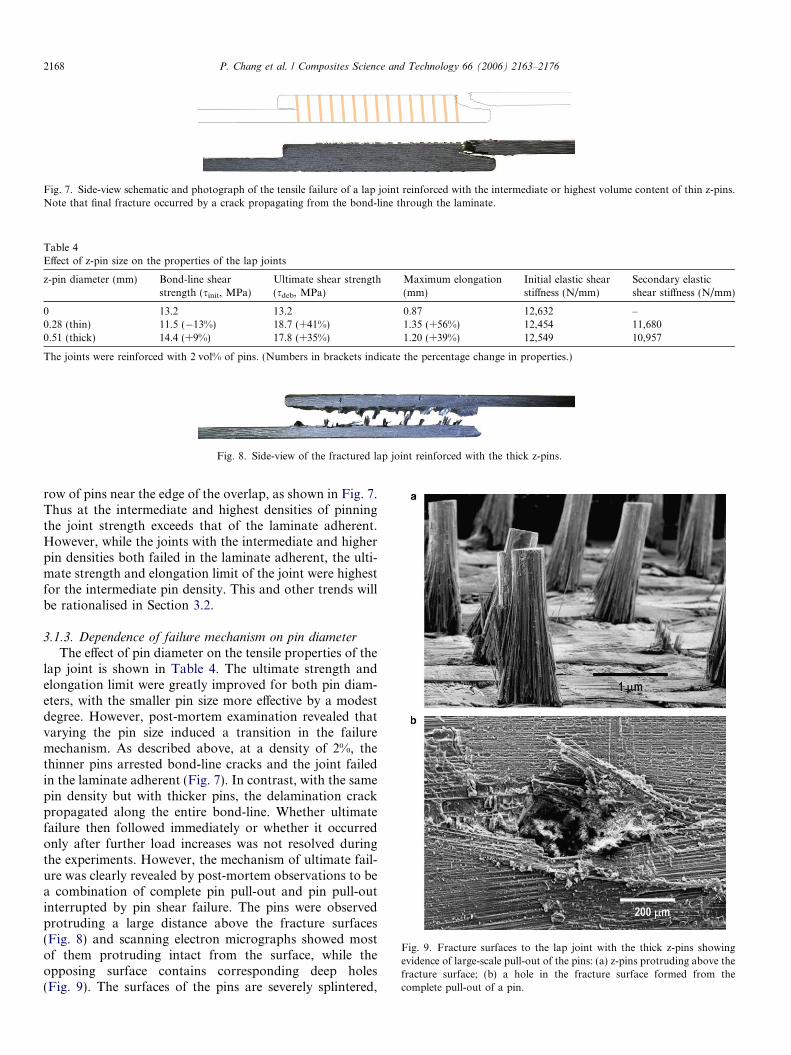
Fig. 7. Side-view schematic and photograph of the tensile failure of a lap joint reinforced with the intermediate or highest volume content of thin z-pins.Note that final fracture occurred by a crack propagating from the bond-line through the laminate.
Table 4Effect of z-pin size on the properties of the lap joints
The joints were reinforced with 2 vol% of pins. (Numbers in brackets indicate the percentage change in properties.)
Fig. 8. Side-view of the fractured lap joint reinforced with the thick z-pins.
Fig. 9. Fracture surfaces to the lap joint with the thick z-pins showingevidence of large-scale pull-out of the pins: (a) z-pins protruding above thefracture surface; (b) a hole in the fracture surface formed from thecomplete pull-out of a pin.
2168 P. Chang et al. / Composites Science and Technology 66 (2006) 2163–2176
row of pins near the edge of the overlap, as shown in Fig. 7.Thus at the intermediate and highest densities of pinningthe joint strength exceeds that of the laminate adherent.However, while the joints with the intermediate and higherpin densities both failed in the laminate adherent, the ulti-mate strength and elongation limit of the joint were highestfor the intermediate pin density. This and other trends willbe rationalised in Section 3.2.
3.1.3. Dependence of failure mechanism on pin diameter
The effect of pin diameter on the tensile properties of thelap joint is shown in Table 4. The ultimate strength andelongation limit were greatly improved for both pin diam-eters, with the smaller pin size more effective by a modestdegree. However, post-mortem examination revealed thatvarying the pin size induced a transition in the failuremechanism. As described above, at a density of 2%, thethinner pins arrested bond-line cracks and the joint failedin the laminate adherent (Fig. 7). In contrast, with the samepin density but with thicker pins, the delamination crackpropagated along the entire bond-line. Whether ultimatefailure then followed immediately or whether it occurredonly after further load increases was not resolved duringthe experiments. However, the mechanism of ultimate fail-ure was clearly revealed by post-mortem observations to bea combination of complete pin pull-out and pin pull-outinterrupted by pin shear failure. The pins were observedprotruding a large distance above the fracture surfaces(Fig. 8) and scanning electron micrographs showed mostof them protruding intact from the surface, while theopposing surface contains corresponding deep holes(Fig. 9). The surfaces of the pins are severely splintered,
1 10 100 1000 10000 100000 10000000
5
10
15
20
0.0% z-pins 0.5% z-pins 2.0% z-pins 4.0% z-pins
Lap
Join
t Fat
igue
She
ar S
tres
s (M
Pa)
Cycles to Failure
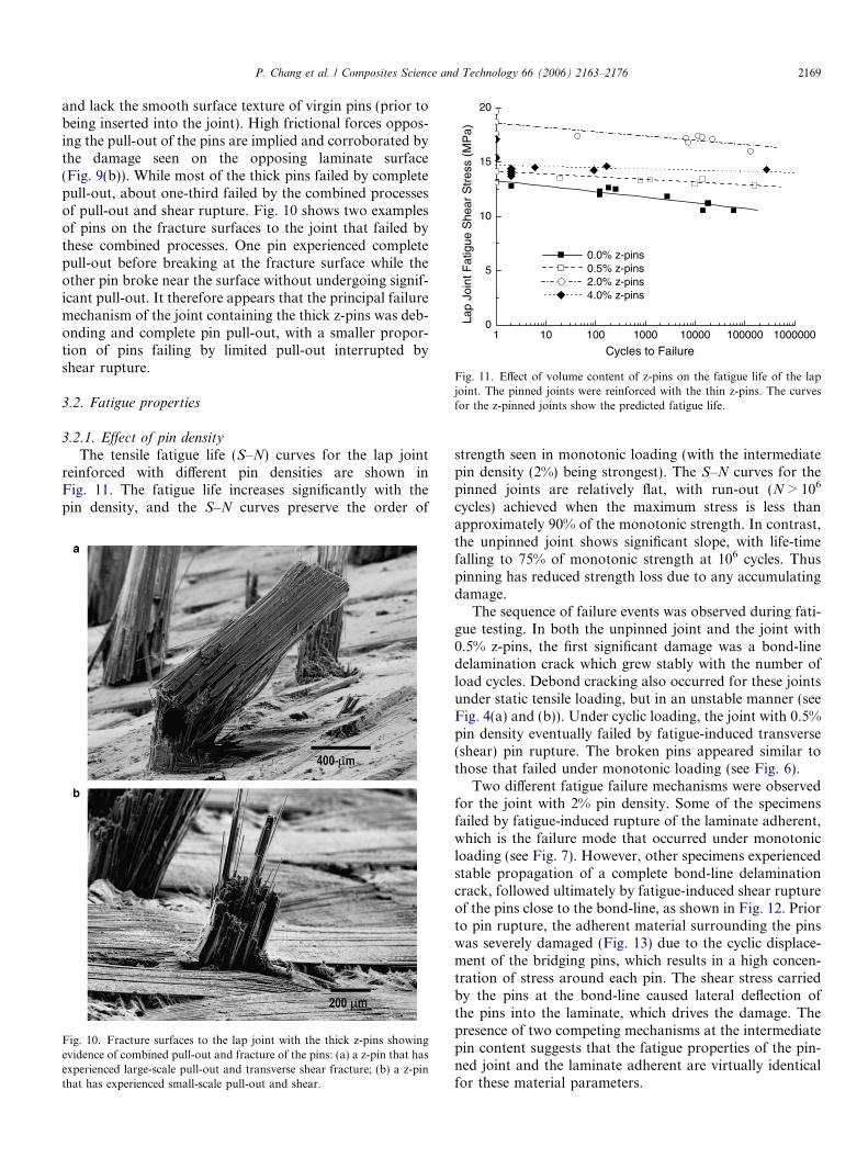
Fig. 11. Effect of volume content of z-pins on the fatigue life of the lapjoint. The pinned joints were reinforced with the thin z-pins. The curvesfor the z-pinned joints show the predicted fatigue life.
P. Chang et al. / Composites Science and Technology 66 (2006) 2163–2176 2169
and lack the smooth surface texture of virgin pins (prior tobeing inserted into the joint). High frictional forces oppos-ing the pull-out of the pins are implied and corroborated bythe damage seen on the opposing laminate surface(Fig. 9(b)). While most of the thick pins failed by completepull-out, about one-third failed by the combined processesof pull-out and shear rupture. Fig. 10 shows two examplesof pins on the fracture surfaces to the joint that failed bythese combined processes. One pin experienced completepull-out before breaking at the fracture surface while theother pin broke near the surface without undergoing signif-icant pull-out. It therefore appears that the principal failuremechanism of the joint containing the thick z-pins was deb-onding and complete pin pull-out, with a smaller propor-tion of pins failing by limited pull-out interrupted byshear rupture.
3.2. Fatigue properties
3.2.1. Effect of pin density
The tensile fatigue life (S–N) curves for the lap jointreinforced with different pin densities are shown inFig. 11. The fatigue life increases significantly with thepin density, and the S–N curves preserve the order of
Fig. 10. Fracture surfaces to the lap joint with the thick z-pins showingevidence of combined pull-out and fracture of the pins: (a) a z-pin that hasexperienced large-scale pull-out and transverse shear fracture; (b) a z-pinthat has experienced small-scale pull-out and shear.
strength seen in monotonic loading (with the intermediatepin density (2%) being strongest). The S–N curves for thepinned joints are relatively flat, with run-out (N > 106
cycles) achieved when the maximum stress is less thanapproximately 90% of the monotonic strength. In contrast,the unpinned joint shows significant slope, with life-timefalling to 75% of monotonic strength at 106 cycles. Thuspinning has reduced strength loss due to any accumulatingdamage.
The sequence of failure events was observed during fati-gue testing. In both the unpinned joint and the joint with0.5% z-pins, the first significant damage was a bond-linedelamination crack which grew stably with the number ofload cycles. Debond cracking also occurred for these jointsunder static tensile loading, but in an unstable manner (seeFig. 4(a) and (b)). Under cyclic loading, the joint with 0.5%pin density eventually failed by fatigue-induced transverse(shear) pin rupture. The broken pins appeared similar tothose that failed under monotonic loading (see Fig. 6).
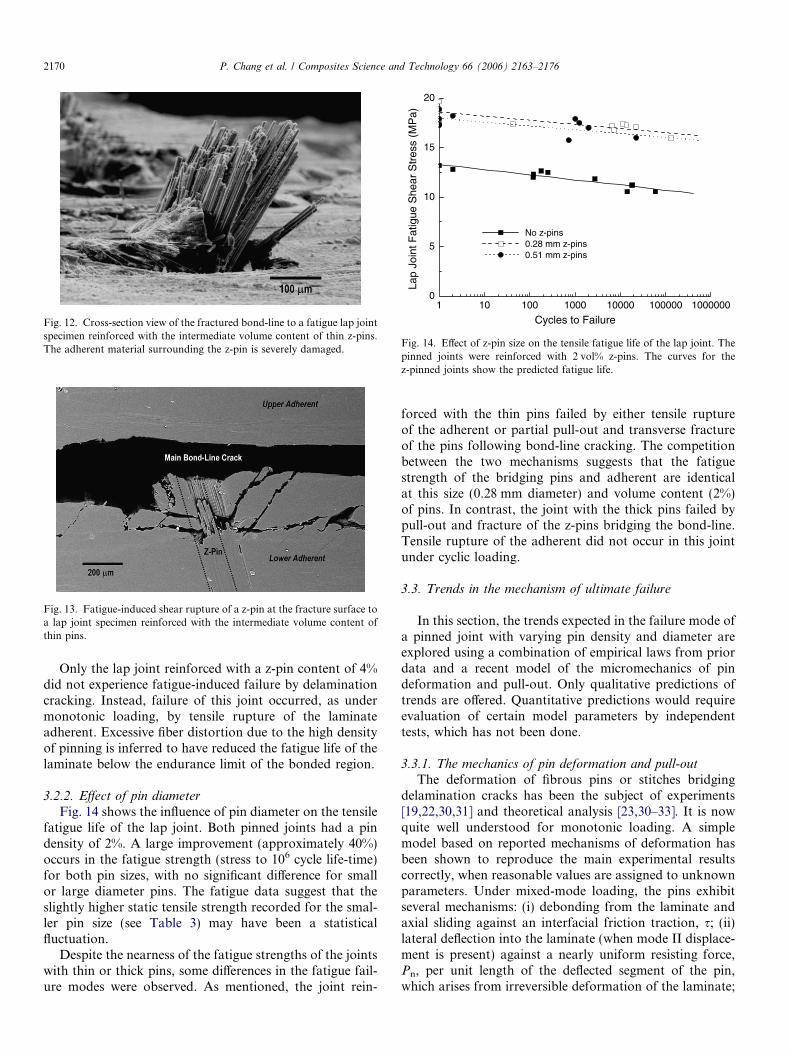
Two different fatigue failure mechanisms were observedfor the joint with 2% pin density. Some of the specimensfailed by fatigue-induced rupture of the laminate adherent,which is the failure mode that occurred under monotonicloading (see Fig. 7). However, other specimens experiencedstable propagation of a complete bond-line delaminationcrack, followed ultimately by fatigue-induced shear ruptureof the pins close to the bond-line, as shown in Fig. 12. Priorto pin rupture, the adherent material surrounding the pinswas severely damaged (Fig. 13) due to the cyclic displace-ment of the bridging pins, which results in a high concen-tration of stress around each pin. The shear stress carriedby the pins at the bond-line caused lateral deflection ofthe pins into the laminate, which drives the damage. Thepresence of two competing mechanisms at the intermediatepin content suggests that the fatigue properties of the pin-ned joint and the laminate adherent are virtually identicalfor these material parameters.
Fig. 13. Fatigue-induced shear rupture of a z-pin at the fracture surface toa lap joint specimen reinforced with the intermediate volume content ofthin pins.
1 10 100 1000 10000 100000 10000000
5
10
15
20
No z-pins0.28 mm z-pins0.51 mm z-pins
Lap
Join
t Fat
igue
She
ar S
tres
s (M
Pa)
Cycles to Failure
Fig. 14. Effect of z-pin size on the tensile fatigue life of the lap joint. Thepinned joints were reinforced with 2 vol% z-pins. The curves for thez-pinned joints show the predicted fatigue life.
Fig. 12. Cross-section view of the fractured bond-line to a fatigue lap jointspecimen reinforced with the intermediate volume content of thin z-pins.The adherent material surrounding the z-pin is severely damaged.
2170 P. Chang et al. / Composites Science and Technology 66 (2006) 2163–2176
Only the lap joint reinforced with a z-pin content of 4%did not experience fatigue-induced failure by delaminationcracking. Instead, failure of this joint occurred, as undermonotonic loading, by tensile rupture of the laminateadherent. Excessive fiber distortion due to the high densityof pinning is inferred to have reduced the fatigue life of thelaminate below the endurance limit of the bonded region.
3.2.2. Effect of pin diameter
Fig. 14 shows the influence of pin diameter on the tensilefatigue life of the lap joint. Both pinned joints had a pindensity of 2%. A large improvement (approximately 40%)occurs in the fatigue strength (stress to 106 cycle life-time)for both pin sizes, with no significant difference for smallor large diameter pins. The fatigue data suggest that theslightly higher static tensile strength recorded for the smal-ler pin size (see Table 3) may have been a statisticalfluctuation.
Despite the nearness of the fatigue strengths of the jointswith thin or thick pins, some differences in the fatigue fail-ure modes were observed. As mentioned, the joint rein-
forced with the thin pins failed by either tensile ruptureof the adherent or partial pull-out and transverse fractureof the pins following bond-line cracking. The competitionbetween the two mechanisms suggests that the fatiguestrength of the bridging pins and adherent are identicalat this size (0.28 mm diameter) and volume content (2%)of pins. In contrast, the joint with the thick pins failed bypull-out and fracture of the z-pins bridging the bond-line.Tensile rupture of the adherent did not occur in this jointunder cyclic loading.
3.3. Trends in the mechanism of ultimate failure
In this section, the trends expected in the failure mode ofa pinned joint with varying pin density and diameter areexplored using a combination of empirical laws from priordata and a recent model of the micromechanics of pindeformation and pull-out. Only qualitative predictions oftrends are offered. Quantitative predictions would requireevaluation of certain model parameters by independenttests, which has not been done.
3.3.1. The mechanics of pin deformation and pull-outThe deformation of fibrous pins or stitches bridging
delamination cracks has been the subject of experiments[19,22,30,31] and theoretical analysis [23,30–33]. It is nowquite well understood for monotonic loading. A simplemodel based on reported mechanisms of deformation hasbeen shown to reproduce the main experimental resultscorrectly, when reasonable values are assigned to unknownparameters. Under mixed-mode loading, the pins exhibitseveral mechanisms: (i) debonding from the laminate andaxial sliding against an interfacial friction traction, s; (ii)lateral deflection into the laminate (when mode II displace-ment is present) against a nearly uniform resisting force,Pn, per unit length of the deflected segment of the pin,which arises from irreversible deformation of the laminate;
P. Chang et al. / Composites Science and Technology 66 (2006) 2163–2176 2171
(iii) enhancement of interfacial friction (snubbing effect) bya factor ge where lateral deflection has occurred; (iv) stablepull-out up to a critical load, which, as a result of snubbing,can be substantially higher in mixed-mode conditions thanthe load required for pull-out in mode I; (v) ultimate failureby either unstable pull-out or shear failure of the pin, thelatter possibly occurring prior to the end of the stablepull-out phase, but not after it, since the load is thendecreasing.
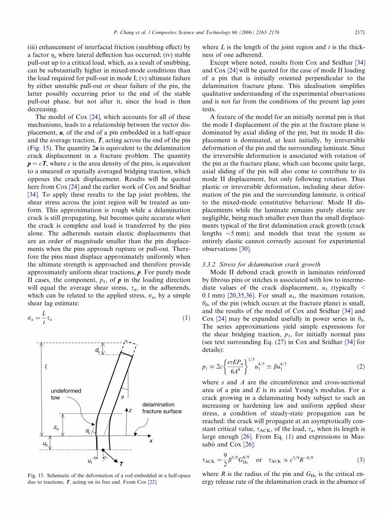
The model of Cox [24], which accounts for all of thesemechanisms, leads to a relationship between the vector dis-placement, u, of the end of a pin embedded in a half-spaceand the average traction, T, acting across the end of the pin(Fig. 15). The quantity 2u is equivalent to the delaminationcrack displacement in a fracture problem. The quantityp = cT, where c is the area density of the pins, is equivalentto a smeared or spatially averaged bridging traction, whichopposes the crack displacement. Results will be quotedhere from Cox [24] and the earlier work of Cox and Sridhar[34]. To apply these results to the lap joint problem, theshear stress across the joint region will be treated as uni-form. This approximation is rough while a delaminationcrack is still propagating, but becomes quite accurate whenthe crack is complete and load is transferred by the pinsalone. The adherends sustain elastic displacements thatare an order of magnitude smaller than the pin displace-ments when the pins approach rupture or pull-out. There-fore the pins must displace approximately uniformly whenthe ultimate strength is approached and therefore provideapproximately uniform shear tractions, p. For purely modeII cases, the component, p1, of p in the loading directionwill equal the average shear stress, sa, in the adherends,which can be related to the applied stress, ra, by a simpleshear lag estimate:
ra ¼Ltsa ð1Þ
ds
z0
φ
θ0
lr
u1
delaminationfracture surfacez
x
T
u3
undeformedtow
Fig. 15. Schematic of the deformation of a rod embedded in a half-spacedue to tractions, T, acting on its free end. From Cox [22].
where L is the length of the joint region and t is the thick-ness of one adherend.
Except where noted, results from Cox and Sridhar [34]and Cox [24] will be quoted for the case of mode II loadingof a pin that is initially oriented perpendicular to thedelamination fracture plane. This idealisation simplifiesqualitative understanding of the experimental observationsand is not far from the conditions of the present lap jointtests.
A feature of the model for an initially normal pin is thatthe mode I displacement of the pin at the fracture plane isdominated by axial sliding of the pin; but its mode II dis-placement is dominated, at least initially, by irreversibledeformation of the pin and the surrounding laminate. Sincethe irreversible deformation is associated with rotation ofthe pin at the fracture plane, which can become quite large,axial sliding of the pin will also come to contribute to itsmode II displacement, but only following rotation. Thusplastic or irreversible deformation, including shear defor-mation of the pin and the surrounding laminate, is criticalto the mixed-mode constitutive behaviour. Mode II dis-placements while the laminate remains purely elastic arenegligible, being much smaller even than the small displace-ments typical of the first delamination crack growth (cracklengths �5 mm); and models that treat the system asentirely elastic cannot correctly account for experimentalobservations [30].
3.3.2. Stress for delamination crack growth
Mode II debond crack growth in laminates reinforcedby fibrous pins or stitches is associated with low to interme-diate values of the crack displacement, u1 (typically <0.1 mm) [20,35,36]. For small u1, the maximum rotation,h0, of the pin (which occurs at the fracture plane) is small,and the results of the model of Cox and Sridhar [34] andCox [24] may be expanded usefully in power series in h0.The series approximations yield simple expressions forthe shear bridging traction, p1, for initially normal pins(see text surrounding Eq. (27) in Cox and Sridhar [34] fordetails):
p1 � 2cssEP n
6A4
� �1=5
u4=51 � bu4=5
1 ð2Þ
where s and A are the circumference and cross-sectionalarea of a pin and E is its axial Young’s modulus. For acrack growing in a delaminating body subject to such anincreasing or hardening law and uniform applied shearstress, a condition of steady-state propagation can bereached: the crack will propagate at an asymptotically con-stant critical value, sACK, of the load, sa, when its length islarge enough [26]. From Eq. (1) and expressions in Mas-sabo and Cox [26]:
sACK ¼9
2b5=9G4=9
IIc or sACK / c5=9R�4=9 ð3Þ
where R is the radius of the pin and GIIc is the critical en-ergy release rate of the delamination crack in the absence of
pin area fraction, c
criti
cal a
ppl
ied
sh
ear
stre
ss,τ
a
0.5 2 4
adherendfailure (τt)
pin pullout (τp)
pin shearrupture (τr)
ACK stress(τACK)
debondinitiation
DD
D
Fig. 16. Trends in the critical applied shear stress for various failureevents in a pinned lap joint.
2172 P. Chang et al. / Composites Science and Technology 66 (2006) 2163–2176
pin bridging (the intrinsic delamination toughness of theresin).
If the shear stresses in the adherends of the lap joint areuniform during debond crack growth, then sa = sACK canbe used as a guide to the resistance of the joint to debond-ing (i.e., crack propagation without pin failure or pull-out).That is, while sACK cannot completely describe crack prop-agation in the lap joint (the critical stress will in fact dependon crack length), variations of sACK with pin diameter anddensity should reflect expected variations of the actualpropagation stress. For fixed R, sACK rises with c; for fixedc, it rises with decreasing R (i.e., fine pins are more efficientcrack stoppers).
3.3.3. Stress for unstable pin pull-out
The model of Cox [24] provides an estimate of the dis-placement and tractions, u and T, at the point at whichthe pins become unstable (i.e., beyond which the loaddecreases to complete pull-out) in the purely mode II case.The corresponding value, sp, of sa for the joint followsfrom sa = cT1. The critical shear stress shows the followingapproximate proportionalities (Eq. (36) in Cox [24]):
sp / clR
lP n
ss
� �1=2
ð4Þ
where l is the half length of the pin, l is the coefficient offriction at the pin/laminate interface (order unity), and sis the initial (unenhanced) value of the friction stress. FromCox [24], Pn � 2Rrh, where rh is the (nearly hydrostatic)compression in the laminate ahead of the deflecting pin.Limited data suggest that rh, s, and l are material con-stants for a given laminate [24]. Therefore Pn/ss is neutralunder changes in R; and sp rises linearly with the pin den-sity, c, and falls linearly with the pin diameter.
3.3.4. Stress for shear rupture of pins
In the absence of contradicting data, the shear strength ofa pin will be assumed to be a material property, independentof the pin diameter. Thus the critical applied shear stress(averaged over the joint) for pin rupture, sr, is given by
sr ¼ ccr ð5Þwhere cr is a constant.
3.3.5. Critical stress for tensile adherend failure
Empirical evidence shows that the strength of an unnot-ched composite panel falls approximately linearly withincreasing pin density and linearly with increasing pindiameter [17,25]. The critical applied shear stress, st, atwhich tensile adherend failure will occur, usually at anextremity of the joint, may therefore be written using Eq.(1) together with Eq. (1) of Chang et al. [25];
st ¼ ctð1� acDÞ ð6Þwhere ct and a are constants. From Chang et al. [25], a rea-sonable estimate of a for the present 0/90� woven laminatesis a � 7 mm�1.
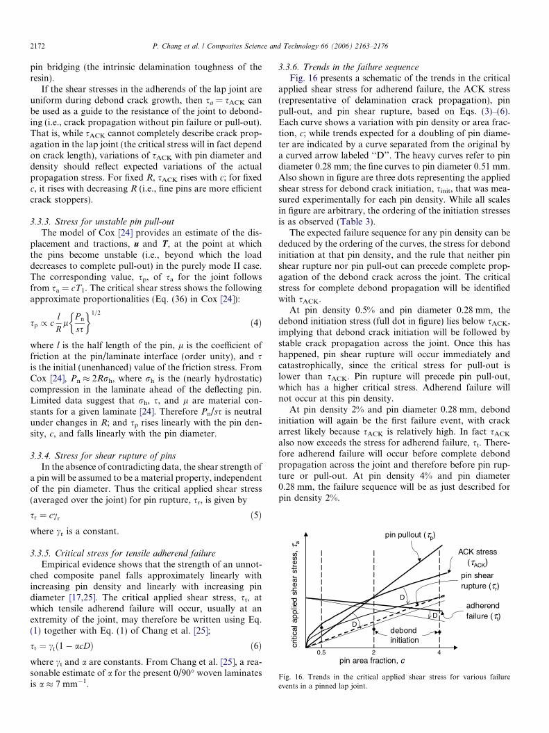
3.3.6. Trends in the failure sequence
Fig. 16 presents a schematic of the trends in the criticalapplied shear stress for adherend failure, the ACK stress(representative of delamination crack propagation), pinpull-out, and pin shear rupture, based on Eqs. (3)–(6).Each curve shows a variation with pin density or area frac-tion, c; while trends expected for a doubling of pin diame-ter are indicated by a curve separated from the original bya curved arrow labeled ‘‘D’’. The heavy curves refer to pindiameter 0.28 mm; the fine curves to pin diameter 0.51 mm.Also shown in figure are three dots representing the appliedshear stress for debond crack initiation, sinit, that was mea-sured experimentally for each pin density. While all scalesin figure are arbitrary, the ordering of the initiation stressesis as observed (Table 3).
The expected failure sequence for any pin density can bededuced by the ordering of the curves, the stress for debondinitiation at that pin density, and the rule that neither pinshear rupture nor pin pull-out can precede complete prop-agation of the debond crack across the joint. The criticalstress for complete debond propagation will be identifiedwith sACK.
At pin density 0.5% and pin diameter 0.28 mm, thedebond initiation stress (full dot in figure) lies below sACK,implying that debond crack initiation will be followed bystable crack propagation across the joint. Once this hashappened, pin shear rupture will occur immediately andcatastrophically, since the critical stress for pull-out islower than sACK. Pin rupture will precede pin pull-out,which has a higher critical stress. Adherend failure willnot occur at this pin density.
At pin density 2% and pin diameter 0.28 mm, debondinitiation will again be the first failure event, with crackarrest likely because sACK is relatively high. In fact sACK
also now exceeds the stress for adherend failure, st. There-fore adherend failure will occur before complete debondpropagation across the joint and therefore before pin rup-ture or pull-out. At pin density 4% and pin diameter0.28 mm, the failure sequence will be as just described forpin density 2%.
P. Chang et al. / Composites Science and Technology 66 (2006) 2163–2176 2173
When the pin diameter is increased to 0.51 mm, thesequences of failure events at different pin densities change,as follows. At pin density 0.5%, the debond initiation stressis now above sACK. Therefore, debond crack propagation,still the first failure event, will be unstable. The stress forpin pull-out has also decreased, to be now lower than thatfor pin rupture. Therefore, ultimate failure will be by pinpull-out, which will occur catastrophically after completedebond crack initiation, since sp < sinit.
At pin density 2% and pin diameter 0.51 mm, debondinitiation is the first failure event and sACK is a higherstress, so that debond crack propagation is stable. How-ever, sACK is lower than the stress for adherend failure,st, and therefore, unlike the case for pin diameter0.28 mm, debond propagation will proceed to completion,after which pin pull-out is expected to occur catastrophi-cally, since sp < sACK and sp < sr.
At pin density 4% and pin diameter 0.51 mm, the failuresequence will be as for pin diameter 0.28 mm: debond ini-tiation will be the first failure event, but since sACK exceedsst, adherend failure will occur before complete debondpropagation across the joint.
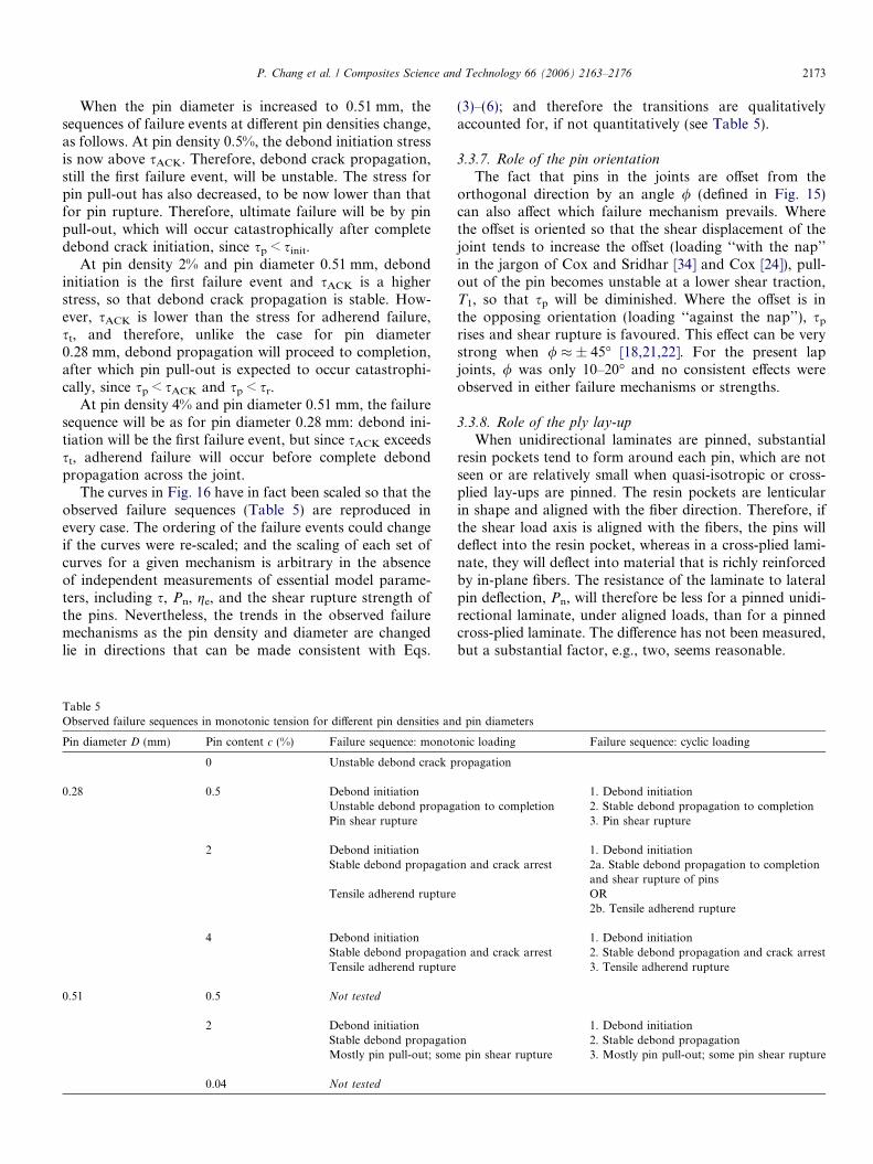
The curves in Fig. 16 have in fact been scaled so that theobserved failure sequences (Table 5) are reproduced inevery case. The ordering of the failure events could changeif the curves were re-scaled; and the scaling of each set ofcurves for a given mechanism is arbitrary in the absenceof independent measurements of essential model parame-ters, including s, Pn, ge, and the shear rupture strength ofthe pins. Nevertheless, the trends in the observed failuremechanisms as the pin density and diameter are changedlie in directions that can be made consistent with Eqs.
Table 5Observed failure sequences in monotonic tension for different pin densities an
Pin diameter D (mm) Pin content c (%) Failure sequence: monoto
2 Debond initiationStable debond propagatiMostly pin pull-out; som
0.04 Not tested
(3)–(6); and therefore the transitions are qualitativelyaccounted for, if not quantitatively (see Table 5).
3.3.7. Role of the pin orientation
The fact that pins in the joints are offset from theorthogonal direction by an angle / (defined in Fig. 15)can also affect which failure mechanism prevails. Wherethe offset is oriented so that the shear displacement of thejoint tends to increase the offset (loading ‘‘with the nap’’in the jargon of Cox and Sridhar [34] and Cox [24]), pull-out of the pin becomes unstable at a lower shear traction,T1, so that sp will be diminished. Where the offset is inthe opposing orientation (loading ‘‘against the nap’’), sp
rises and shear rupture is favoured. This effect can be verystrong when / � ± 45� [18,21,22]. For the present lapjoints, / was only 10–20� and no consistent effects wereobserved in either failure mechanisms or strengths.
3.3.8. Role of the ply lay-up
When unidirectional laminates are pinned, substantialresin pockets tend to form around each pin, which are notseen or are relatively small when quasi-isotropic or cross-plied lay-ups are pinned. The resin pockets are lenticularin shape and aligned with the fiber direction. Therefore, ifthe shear load axis is aligned with the fibers, the pins willdeflect into the resin pocket, whereas in a cross-plied lami-nate, they will deflect into material that is richly reinforcedby in-plane fibers. The resistance of the laminate to lateralpin deflection, Pn, will therefore be less for a pinned unidi-rectional laminate, under aligned loads, than for a pinnedcross-plied laminate. The difference has not been measured,but a substantial factor, e.g., two, seems reasonable.
d pin diameters
nic loading Failure sequence: cyclic loading
ropagation
1. Debond initiationation to completion 2. Stable debond propagation to completion
3. Pin shear rupture
1. Debond initiationon and crack arrest 2a. Stable debond propagation to completion
and shear rupture of pinsOR2b. Tensile adherend rupture
1. Debond initiationon and crack arrest 2. Stable debond propagation and crack arrest
Fig. 17. Calculated S–logN curves with the lap joints with: (a) differentvolume contents and (b) diameters of z-pin reinforcement.
2174 P. Chang et al. / Composites Science and Technology 66 (2006) 2163–2176
Eqs. (2) and (3) show that the resulting change in sACK
will remain modest, since sACK / (Pn)1/9. Eq. (4) predicts amuch greater change in sp, with sp / (Pn)1/2. Other failuremechanisms are predicted to be weakly affected. Thus pinpull-out will tend to be more prevalent in pinned unidirec-tional laminates under aligned shear loading than in pinnedcross-plied laminates.
3.4. Modelling the fatigue life
The linear S–logN data for the unpinned and pinnedjoints presented in Figs. 11 and 14 can be fitted quite wellby Basquin’s law:
Smax ¼ S0 þ m log N ð5Þwhere Smax is the peak fatigue stress acting on the pinnedjoint, N is the number of load cycles to failure, and S0 andm are fitted constants (S0 being the static strength). Thevalues of m found by linear regression analysis are listed inTable 6. The expected errors in m are large because of the rel-atively small amount of data for each joint type. A tendencyexists for m to be lower for the pinned joints, indicating thattheir tensile fatigue strength is less sensitive to cyclic degra-dation than the unpinned specimen. However, because ofthe large statistical uncertainty, the values of m for eitherthe small pins at the two lower area fractions, 0.5%, 2.0%,or the large pins are not clearly different from its value forthe unpinned joint. All of these joints failed in the bond-line,except for a few of the specimens with 2.0% small pins. Incontrast, when failure occurred in the laminate adherent(i.e., small pins at 4% area fraction), m takes a statisticallysignificant lower value for the pinned joint. This suggeststhat the fatigue strength of the adherent is less sensitive tocyclic degradation than the pins bridging the bond-line.
Mouritz and Cox [37] showed that the compressive fati-gue life of flat stitched laminate coupons are well fitted bythe modified Basquin law:
Smax ¼~SS0
ðS0 þ m0 log NÞ ð6Þ
where m0 is the slope of the S–logN curves for the un-stitched material. The term, ~S=S0, represents the knock-down (<1) or knock-up (>1) factor in static strength dueto the stitching. This equation was found to accurately pre-dict the S–logN curves of stitched laminates provided theyhad a value of m0 similar to that of the unstitched material.The advantage of Eq. (6) is that the fatigue life of a stitchedlaminate can be estimated using three empirically deter-
mined constants: the ultimate strengths of the stitchedand unstitched materials and the m value of the unstitchedmaterial. If fatigue life data are available for unstitchedmaterial, only the static strength of the stitched materialneeds be measured to estimate its S–logN curve, eliminat-ing the need for time-consuming and expensive fatiguetests, at least for initial design studies. However, this empir-ical result is probably only valid when the fatigue failuremechanisms of the stitched and unstitched laminates aresimilar. If they are dissimilar, the value of m is likely tobe affected and the correlation would become poor.
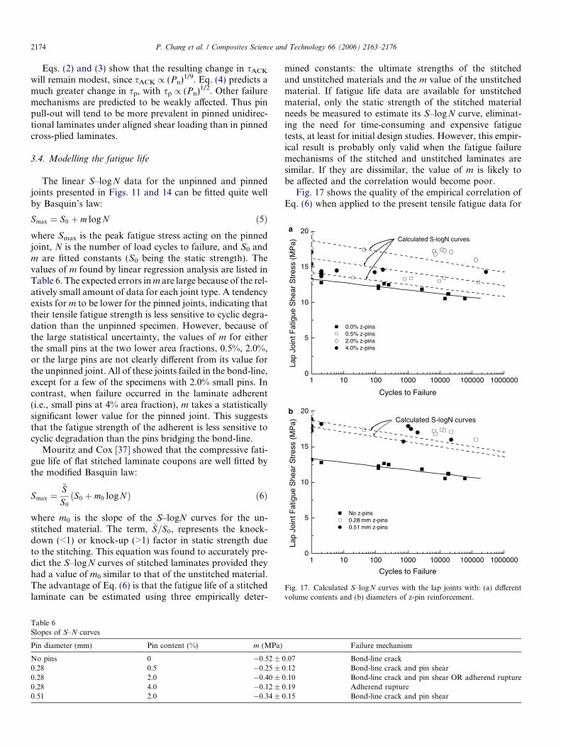
Fig. 17 shows the quality of the empirical correlation ofEq. (6) when applied to the present tensile fatigue data for
Failure mechanism
.07 Bond-line crack
.12 Bond-line crack and pin shear
.10 Bond-line crack and pin shear OR adherend rupture
.19 Adherend rupture
.15 Bond-line crack and pin shear
P. Chang et al. / Composites Science and Technology 66 (2006) 2163–2176 2175
pinned joints. The S–logN curves in Fig. 17 were calculatedwith Eq. (6) using the m0 value for the unpinned specimen(�0.52) and the static strength values given in Tables 2 and3. The fit to the experimental fatigue data shows sufficientaccuracy for initial engineering design estimates for thejoints with thin pins at area fractions of 0.5% or 2.0%and with thick pins. The correlation is probably goodbecause the dominant fatigue failure mode in both theunpinned and pinned specimens (with the exception of afew samples with 2.0% thin pins) was bond-line cracking.In contrast, the fit is poor for the joint with 4.0% pins,which failed by different mechanisms under fatigue andcyclic loading.
Since the goodness of fit of Eq. (6) depends on consis-tency in the failure mechanisms, caution is due if it is tobe used for initial fatigue design of the pinned case withoutfatigue data for the pinned case. However, in the case ofpinned joints, the transition that is observed for high pinarea fractions results in a lower value of m than for theunpinned joint. Therefore, using Eq. (6) in conjunctionwith S–log N data for the unpinned joint and the staticstrength for the pinned joint will provide conservative esti-mates of the fatigue life of the pinned joint.
4. Conclusions
Through-thickness reinforcement of co-cured single lapjoints using z-pins is an effective method for improvingthe ultimate tensile strength, elongation limit, and fatiguelife. For the processing methods and laminates used forthe lap joints in this study, z-pinning increased the staticstrength by up to 40%, the elongation-to-failure by up to55%, and the fatigue strength (at 106 cycles) by up to 40%.
The tensile properties and failure mechanisms are con-trolled by the volume content and diameter of the z-pins.Pins inhibit delamination crack growth at the resin bond-line and transfer loads even after bond-line cracking. Thesequence of failure mechanisms that lead to ultimate failurefor the joint undergoes a series of transitions with increasingz-pin content. Unstable delamination propagation occur-ring in the absence of pins is replaced by stable crack growthfollowed by shear rupture of the pins at a low pin content(0.5%). At intermediate (2%) and high (4%) pin contents,delamination cracks arrested and failure occurred by tensilerupture of the laminate adherent. The static strength andfailure mechanisms were also affected by the z-pin diameter.For a fixed volume content of z-pins, the static tensilestrength was marginally higher when the joint was rein-forced with smaller pins (0.28 mm) than with larger pins(0.51 mm). Furthermore, the ultimate failure mechanismwas changed from rupture of the laminate adherent in thejoint reinforced with the thinner pins to delamination crack-ing in the joint containing the thicker pins, which ultimatelyfailed by pull-out and/or transverse rupture of the pins.
Prior models of delamination crack propagation and themicromechanisms of pin deformation can account qualita-tively for the observed changes in failure sequences as the
pin diameter and content are varied. While pinning inhibitsdelamination of the bond-line and can defer ultimate fail-ure following bond-line cracking, it also tends to weakenthe adherends, due to damage to the in-plane fibers. There-fore, the maximum benefit for static loading in the presentstudy was found for the intermediate pin density of 2%.
The improvements gained by z-pinning other types ofjoints, such as adhesive bonded joints, or joints withanother geometry, such as double-lap or T-joints, will bedifferent to those reported here for a co-cured single lapjoint containing a brittle resin. The efficacy of z-pinningin improving the properties of other composite joint config-urations is not known, and is a topic worthy of furtherexperimental research and analysis.
Acknowledgements
This research was performed with financial support pro-vided by the Australian Research Council (Grant No.DP0211709). P.C. thanks the CRC for Advanced Compos-ite Structures Ltd. for the provision of a scholarship.B.N.C. was also supported by the US Department of En-ergy (Grant No. DE-FG03-97ER45667).
References
[1] Holt DJ. Future composite aircraft structures may be sewn together.Automot Eng 1982;90(7).
[2] Lee C, Liu D. Tensile strength of stitching joint in woven glassfabrics. J Eng Mater Technol 1990;112:125–30.
[3] Rhodes MD, Williams JG. Concepts for improving damage toleranceof composite compression panels. In: 5th DoD/NASA conference onfibrous composites in structural design; 1981.
[4] Sawyer JW. Effect of stitching on the strength of bonded compositesingle lap joints. AIAA J 1985;23:1744–8.
[5] Tada Y, Ishikawa T. Experimental evaluation of the effects ofstitching on CFRP laminate specimens with various shapes andloadings. Key Eng Mater 1989;37:305–16.
[6] Tong L, Cleaves K, Kruckenburg T, Stevens GP. Strength of RTMsingle lap joints with transverse stitching. Key Eng Mater1998;137:195–202.
[7] Tong L, Jain LK, Leong KH, Kelly D, Herszberg I. Failure oftransversely stitched RTM lap joints. Compos Sci Technol1998;58:221–7.
[8] Aymerich F. Effect of stitching on the static and fatigue performanceof co-cured composite single-lap joints. J Compos Mater2004;36:243–57.
[9] Aymerich F, Onnis R, Priolo P. Analysis of the fracture of a stitchedsingle-lap joint. Composites 2005;36:603–14.
[11] Bradshaw FJ, Dorey G, Sidey GR. Impact resistance of carbon fiberreinforced plastics. Technical Report. Report No.: 72240. Farnbor-ough: Royal Aircraft Establishment; 1973.
[12] Huang SL, Richey RJ, Deska EW. Cross reinforcement in a GR/EPlaminate. In: ASME, Winter Annual Meeting, San Francisco: ASME;1978.
[13] Murrin LJ, Erbacher H, Composite center fuselage – phase I. In: 35thAnnual conference on reinforced plastics and composites; 1980.
[14] Tomashevskii VT, Romanov DA, Shalygin VN, Panfilov NA. Effectof radial reinforcement on the strength of fiberglass shells subjected toloading by external pressure. Mekhanika Kompozitnykh Materialov1980:205–10.
2176 P. Chang et al. / Composites Science and Technology 66 (2006) 2163–2176
[15] Krasnov VI, Kuznetsov VA, Yu A. Automated method of transversereinforcement of composites by short fibers. Mekhanika Kompozit-nykh Materialov 1987;3:449–504.
[16] Tomashevskii VT, Shalygin VN, Romanov DA, Sitnikov SY.Transversal reinforcement of composite materials using ultrasonicvibrations. Mekhanika Kompozitnykh Materialov 1987(6):1068–71.
[18] Freitas G, Fusco T, Campbell T, Harris J, Rosenberg S. Z-fibretechnology and products for enhancing composite design. In: 83rdAGRAD Conference; 1996.
[19] Rugg KL, Cox BN, Ward K, Sherrick GO. Damage mechanisms forangled through-thickness rod reinforcement in carbon-epoxy lami-nates. Compos Part A 1998;29A:1603–13.
[20] Rugg KL, Cox BN, Massabo R. Mixed mode delamination ofpolymer composite laminates reinforced through the thickness by Z-fibers. Composites 2002;33(2):177–90.
[21] Owsley GS. The effect of Z-fiberTM reinforcement on fatigueproperties of stiffened blade panels. In: 15th Technical conferenceof the American composites society, 25–27 Sept., Texas; 2000.
[22] Rugg KL, Cox BN, Massabo R. Mixed mode delamination ofpolymer composite laminates reinforced through the thickness by Z-fibers. Composites 2004;33(2):177–90.
[23] Cartie DR, Cox BN, Fleck NA. Mechanisms of crack bridging bycomposite and metallic rods. Composites 2004;A35:1325–36.
[24] Cox BN. Snubbing effects in the pullout of a fibrous rod from alaminate. Mech Adv Mater Struct 2005;12:85–98.
[25] Chang P, Mouritz AP, Cox BN. Properties and failure mechanisms ofpinned laminates in monotonic and cyclic tension. J Compos Mater[in press].
[26] Massabo R, Cox BN. Concepts for bridged mode II delaminationcracks. J Mech Phys Solids 1999;47:1265–300.
[27] Cox BN, Lo CS. Load ratio, notch, and scale effects for bridgedcracks in fibrous composites. Acta Metall Mater 1992;40:69–80.
[28] Cox BN, Marshall DB. Concepts for bridged cracks in fracture andfatigue. Acta Metall Mater 1994;42(2):341–63.
[29] Cartie DDR, Partridge IK. Delamination behaviour of z-pinnedlaminates. In: Proceedings of the 2nd ESIS TC4 conference. 13–15Sept., Les Diablerets: Elsevier; 1999.
[30] Cox BN, Massabo R, Mumm DR, Turrettini A, Kedward K.Delamination fracture in the presence of through-thickness reinforce-ment. In: 11th International conference on composite materials, GoldCoast, Australia: Technomic Publishing, Lancaster, Pennsylvania;1997.
[31] Turrettini A. Santa Barbara, California, University of California,Santa Barbara; 1996.
[32] Cox BN. A constitutive model for through-thickness reinforce-ment bridging a delamination crack. Adv Compos Lett 1999;8:249–56.
[33] Cox BN. Constitutive model for a fiber tow bridging a delaminationcrack. Mech Compos Mater Struct 1999;6:117–38.
[34] Cox BN, Sridhar N. A traction law for inclined fibre towsbridging mixed mode cracks. Mech Compos Mater Struct 2002;9:299–331.
[35] Massabo R, Mumm DR, Cox BN. Characterizing mode II delam-ination cracks in stitched composites. Int J Fract 1998;92:1–38.
[36] Yang Q, Rugg KL, Cox BN, Shaw MC. Failure in the junction regionof T-stiffeners: 3D-braided vs. 2D tape laminate stiffeners. Int J SolidStruct 2003;4(7):1653–68.
[37] Mouritz AP, Cox BN. A mechanistic approach to the properties ofstitched laminates. Composites 2000;A31:1–27.