13
Property of American Airlines

Prope
rty o
f Am
erica
n Airli
nes

3. OVERHAUL-MAJOR REPAIR
CONTENTS
3.1 Safety instructions.................................................................................................................... 2 3.2 Replacement of 400Hz output cables ...................................................................................... 3 3.3 Replacement of 28VDC output cable (option).......................................................................... 3 3.4 Replacement of overvoltage suppressOr................................................................................. 4 3.5 Replacement of rotating rectifiers ............................................................................................ 4 3.6 Replacement of HItzinger-ACON............................................................................................. 5
3.6.1 Replacement of Touch-Panel ......................................................................................... 5 3.6.2 Replacement of Hitzinger-ACON modules ..................................................................... 6
3.7 Replacement of 200/115V 400Hz voltage regulator ................................................................ 7 3.8 Replacement of 28VDC module (Option)................................................................................. 7 3.9 Replacement of silencer .......................................................................................................... 8 3.10 Repair instructions for GRP parts (Canopy) ........................................................................ 9
3.10.1 Dirty surfaces ............................................................................................................. 9 3.10.2 Scratched surfaces .................................................................................................... 9 3.10.3 Repair of deeply scratched surfaces with Gelcoat ................................................... 10 3.10.4 Repair of deep scratches with filling compound and varnish ................................... 10 3.10.5 Damaged surfaces with a continuous tear, accessible from the inside.................... 11 3.10.6 Damaged surfaces with a continuous tear, not accessible from the inside.............. 12 3.10.7 Ripped out metal parts ............................................................................................. 12
D POWER1 Edition 01 - Page 1 / 12
Prope
rty o
f Am
erica
n Airli
nes

3. OVERHAUL-MAJOR REPAIR
3.1 Safety instructions
This instruction acts as a guide, it cannot cover all detailed actions for disassembly or reassemble the unit. The maintenance and inspection of the unit must not be performed by unskilled personnel and personnel without introduction. Where tools, materials, or working methods are selected that have not particularly been recommended by Hitzinger, it is up to the individual user’s assessment whether this might lead to dangerous situations for him or others or might entail damages to the unit. We do not assume any guarantees for damages to the unit that have resulted from incorrect mounting. Therefore please carefully follow the instructions in the respective parts.
WARNING !
To avoid starting GPU, switch off battery main switch, before carrying any repair work! Be aware that batteries are not short circuited!
NOTE !
Before electrical cables or wires are disconnected they should be clearly identified to ensure correct replacement! When removing or replacing any wires, leads or cables during removal or installation operations, refer to the wiring diagrams.
D POWER1 Edition 01 - Page 2 / 12
Prope
rty o
f Am
erica
n Airli
nes

3. OVERHAUL-MAJOR REPAIR
3.2 Replacement of 400Hz output cables
1) Disconnect cable connections in 400Hz switch panel - phases, EF-contact, 90%-contact (Option), neutral and ground.
2) Loosen cable gland in switch panel and pull cables out of 400Hz switch panel. 3) Draw in new cable(s) and redo all electrical connections. 4) Tighten cable gland in 400Hz switch panel.
3.3 Replacement of 28VDC output cable (option)
1) Remove cover. 2) Disconnect/pull out cable connections on 28VDCPower Stack -
2x Plus, 2x Minus, Pilot-contact. 3) Loosen cable gland and pull cables out. 4) Draw in new cable and redo all electrical connections. 5) Tighten cable gland. 6) Mount cover.
D POWER1 Edition 01 - Page 3 / 12
Prope
rty o
f Am
erica
n Airli
nes

3. OVERHAUL-MAJOR REPAIR
3.4 Replacement of overvoltage suppressor
1) Remove cover. 2) Mark and unscrew electrical connections. 3) Remove overvoltage suppressor. 4) Mount new suppressor. 5) Redo electrical connections. (Torque 6 Nm). 6) Mount cover.
3.5 Replacement of rotating rectifiers
1) Remove cover. 2) Undo and mark rectifier bridge connections. 3) Remove defective bridge. 4) Coat new rectifier with conductive paste and mount it
(Torque 5 Nm). 5) Redo electrical connections (Torque 6 Nm). 6) Mount cover.
D POWER1 Edition 01 - Page 4 / 12
Prope
rty o
f Am
erica
n Airli
nes
3. OVERHAUL-MAJOR REPAIR
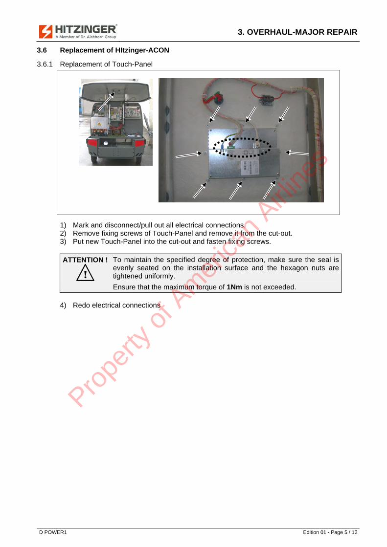
3.6 Replacement of HItzinger-ACON
3.6.1 Replacement of Touch-Panel
1) Mark and disconnect/pull out all electrical connections. 2) Remove fixing screws of Touch-Panel and remove it from the cut-out. 3) Put new Touch-Panel into the cut-out and fasten fixing screws.
ATTENTION !
To maintain the specified degree of protection, make sure the seal is evenly seated on the installation surface and the hexagon nuts are tightened uniformly.
Ensure that the maximum torque of 1Nm is not exceeded.
4) Redo electrical connections
D POWER1 Edition 01 - Page 5 / 12
Prope
rty o
f Am
erica
n Airli
nes

3. OVERHAUL-MAJOR REPAIR
3.6.2 Replacement of Hitzinger-ACON modules
11
12 11
11
11
1
Power
2 3 4
5 6 7 8
9
Error
101112
13141516
012
HighLow
Addr.
13
14
1) Disconnect all plugs from module. 2) Remove module by means of screwdriver. 3) Notice coding position (relevant for input- and output modules). 4) Notice position HI or LO (relevant only for input modules).
1
Power
2 3 4
5 6 7 8
9
Error
101112
13141516
012
HighLow
Addr.
115
16
17 18 1811
18 181
5) Set coding to noticed position (relevant for input- and output modules). 6) Set switch to noticed position (relevant only for input modules). 7) Put module on cross rail. 8) Redo all connections.
D POWER1 Edition 01 - Page 6 / 12
Prope
rty o
f Am
erica
n Airli
nes

3. OVERHAUL-MAJOR REPAIR
3.7 Replacement of 200/115V 400Hz voltage regulator
T21: 1) Remove cable tie. 2) Disconnect regulator plug. 3) Remove regulator cover by unscrewing 4 screws. 4) Remove regulator by unscrewing 4 spacer screws. 5) Screw in new regulator. 6) Mount regulator cover. 7) Plug in regulator plug. 8) Secure regulator plug via cable tie. 9) Turn both potentiometers fully clockwise and then back to vertical position.
Do not turn to minimum or maximum position.
AVC63: Remove all connections, exchange regulator and redo all connections. Potentiometer „DRP“ (Line Drop Compensation) turn fully counterclockwise. Potentiometer „STB“ (Stability) turn to 8 o’clock. Remove connections 2 and 3, short terminals 2 and 3, adjust potentiometer „VLT ADJ“ (voltage adjust) at no load to nominal voltage 115 V (L-N) and finally reconnect terminals 2 and 3.
3.8 Replacement of 28VDC module (Option)
1) Remove cover. 2) Mark and disconnect/pull out all electrical connections. 3) Unscrew 28VDC module. 4) Mount new 28VDC module. 5) Redo all electrical connections.
ACV63
T21 1 2
4
3
D POWER1 Edition 01 - Page 7 / 12
Prope
rty o
f Am
erica
n Airli
nes

3. OVERHAUL-MAJOR REPAIR
3.9 Replacement of silencer
1) Loosen locking device of air outlet duct on the bottom left and right. 2) Remove air outlet duct through two persons by lifting up (~40mm) and carefully move
forward.
NOTE !
Lower air outlet duct carefully on a prepared soft padded surface (for example foam or cardboard) to avoid scratch of glass-fibre-surface.
3) Remove exhaust lines. 4) Secure silencer via crane. 5) Remove silencer and replace it with a new one. 6) Mount new silencer with 2 screws on each side. 7) Mount exhaust lines. 8) Mount air outlet duct carefully. 9) Snap in locking device of air outlet duct on the bottom left and right.
D POWER1 Edition 01 - Page 8 / 12
Prope
rty o
f Am
erica
n Airli
nes

3. OVERHAUL-MAJOR REPAIR
3.10 Repair instructions for GRP parts (Canopy)
FPC Surface FPC = Fiber Polymer Composite
1) Dirty surfaces 2) Slightly scratched surfaces 3) Repair of deeply scratched surfaces with Gelcoat 4) Repair of deeply scratched filling compound and varnish 5) damaged surfaces with a continuous tear, 6) accessible from the inside 7) damaged surfaces with a continuous tear, 8) not accessible from the inside 9) ripped out metal parts
3.10.1 Dirty surfaces
are washed using cleaning materials Warning! Do not use Scotchbrite! Scratching will occur on the Gelcoat surface! After cleaning, wax with a standard commercial finish restorer and polish with a clean cloth. Material: Cleaning materials
Sponge Polishing materials
3.10.2 Scratched surfaces
are cleaned and worked over with very fine wet-or-dry sandpaper, until the scratches are no longer visible. The grit size of the wet-or-dry sandpaper is P320 and higher. Material: Cup with water
Wet-or-dry sandpaper Grit size 320/ 500/ 800 Polishing wool Polishing paste
D POWER1 Edition 01 - Page 9 / 12
Prope
rty o
f Am
erica
n Airli
nes

3. OVERHAUL-MAJOR REPAIR
3.10.3 Repair of deeply scratched surfaces with Gelcoat
The scratches are cleaned, the bad material is removed using a putty knife. The surrounding area 5 mm to the left and right of the scratch should be covered with a ca. 30 mm wide transparent tape (Tesa). Gelcoat is blended in a small cup with 2% hardener, then swabbed onto the washed scratch with a clean, pointed object. Warning on the addition of hardener: Do not use above 3% of the Gelcoat quantity! The hard, projecting Gelcoat is sanded clean using a sanding package (P120), until the residual Gelcoat application has been sanded down. Finally, proceed as in point 2. Material: Putty knife
Cup ca. 300 g Pointed object (e.g. small screwdriver) Gelcoat Gelcoat hardener Dry sandpaper Grit size 120 Cup with water Wet-or-dry sandpaper Grit size 240/ 320/ 500/ 800 Polishing wool Polishing paste
3.10.4 Repair of deep scratches with filling compound and varnish
The deep scratches are washed, and the bad material is removed using a putty knife. The surrounding area 5 mm to the left and right of the scratch should be covered with a ca. 30 mm wide transparent tape (Tesa). The filling compound and hardening paste (2-4%) are mixed well on a hard surface, and the scratch is filled up to slight excess using the putty knife. The hard, excess filling compound is sanded clean with a sanding package (grit size 120), until the camber forms a single plane with the surroundings. Finally, apply the varnish to the repaired location using a brush. Material: Putty knife
Cup 300 g Filling compound Hardening paste for filling compound Flat board for mixing the filling compound Dry sandpaper Grit size 120 Cup with water Wet-or-dry sandpaper Grit size 240/ 320/ 500/ 800 Varnish Varnish hardener
D POWER1 Edition 01 - Page 10 / 12
Prope
rty o
f Am
erica
n Airli
nes

3. OVERHAUL-MAJOR REPAIR
3.10.5 Damaged surfaces with a continuous tear, accessible from the inside
Remove the exposed fibres on the inside, and sand the damaged areas with sandpaper 120 (surrounding +100 mm). Soak 2-3 layers of thin fabric with resin, lay these on the damaged locations, and ventilate them clean with the brush. Clean the tear on the outside, and remove the bad material with a putty knife. The surrounding area 5 mm to the left and right of the scratch should be covered with a ca. 30 mm wide transparent tape (Tesa). Mix the the filling compound and hard paste (2-4%) together well on a hard surface, and fill up the scratch to slight excess. Sand the hardened, projecting filling compound using a sanding package (P120), until the excess filling compound application forms a single plane with the surroundings. Finally, the varnish is applied to the repaired location with a brush. Material: Putty knife
Cup 300 g Resin Resin hardener (2%) Thin fabric Filling compound Hardening paste for filling compound Flat board for mixing the filling compound Dry sandpaper Grit size 120 Cup with water Wet-or-dry sandpaper Grit size 240/ 320/ 500/ 800 Varnish Varnish hardener
D POWER1 Edition 01 - Page 11 / 12
Prope
rty o
f Am
erica
n Airli
nes

3. OVERHAUL-MAJOR REPAIR
D POWER1 Edition 01 - Page 12 / 12
3.10.6 Damaged surfaces with a continuous tear, not accessible from the inside
Remove the exposed fibres on the outside, and sand +50 mm surrounding the damaged locations using a sander (sandpaper P36) ca. 2 mm deep. Soak 2-3 layers of thin fabric with resin, lay these on the damaged locations, and vent them clean with the brush. Mix the filling compound and hardening paste (2-4%) well on a hard surface with a putty knife, and fill out the laminated surface in such a way, that no more depressions are visible. If depressions remain visible following the sanding over of the surface, then repeat the process of the filling compound. Warning! Do not apply too much filling compound material onto the still intact surfaces (this results in uncessary sanding work later)! After completing the sanding work, apply the varnish cleanly using the brush. Material: Sander
Cable Sanding disk Grit size P36 Putty knife Cup 300 g Resin Resin hardener (2%) Thin fabric Filling compound Hardening paste for filling compound Flat board for mixing the filling compound Dry sandpaper Grit size 120 Cup with water Wet-or-dry sandpaper Grit size 240/ 320/ 500/ 800 Varnish Varnish hardener Wooden spatula (doctor’s spatula)
3.10.7 Ripped out metal parts
Ripped out metal parts and FPC surfaces must be freed of any resin and glue residue. Sand using a sanding machine. The locations to be glued must be cleaned, and then newly glued over using glue SS 1515. Material: Sander
Cleaning agent Glue SS 1515+ activating agent Glue gun for Plexus glue Cleaning paper Board for mixing together the two glue ingredients Wooden spatula (doctor’s spatula)
A repair kit is available for this purpose as an option. (Hitzinger class no: 1-000-000-04762)
Prope
rty o
f Am
erica
n Airli
nes


