92
Property of American Airlines
Prope
rty o
f Am
erica
n Airli
nes
Chapter 4: Illustrated Parts List Aug. 1995 Section 4-Contents p. 1
CHAPTER 4Table of Contents
Chapter/Section PageIllustrated Parts List
I. DESCRIPTION 4-1 1
A. INTRODUCTION .......................................................................................................................... 1
B. USING THE ILLUSTRATED PARTS LIST .................................................................................... 1
C ORDERING SPARE PARTS ......................................................................................................... 3
D. VENDOR CODES REFERENCE LIST ......................................................................................... 4
II. ILLUSTRATED PARTS LIST 4-2 1
FIGURE 1: LEFT SIDE BODY COMPONENTS...................................................................................... 1
FIGURE 2: RIGHT SIDE BODY COMPONENTS ................................................................................... 2
FIGURE 3: FRAME WELDMENT ........................................................................................................... 3
FIGURE 4: VEHICLE OPERATOR'S SEAT ASSEMBLY ........................................................................ 4
FIGURE 5: CONTROL PANEL ASSEMBLY ........................................................................................... 5
FIGURE 6: SHIFTER ASSEMBLY .......................................................................................................... 6
FIGURE 7: SHIFTER LINKAGE WELDMENT ........................................................................................ 7
FIGURE 8: ACCELERATOR PEDAL ASSEMBLY .................................................................................. 8
FIGURE 9: BRAKE PEDAL/MASTER CYLINDER ASSEMBLY.............................................................. 9
FIGURE 10: BRAKE LINE DIAGRAM ................................................................................................... 10
FIGURE 11: PARK BRAKE INSTALLATION ......................................................................................... 12
FIGURE 12: PARK BRAKE CABLE LINKAGE...................................................................................... 13
FIGURE 13: REAR BRAKE ASSEMBLY............................................................................................... 14
FIGURE 14: STEER AXLE & HUB ASSEMBLY.................................................................................... 16
FIGURE 15: FRONT DISK BRAKE CALIPER ASSEMBLY .................................................................. 18
FIGURE 16: HEADLIGHT/TURN SIGNAL ASSEMBLIES .................................................................... 19
Prope
rty o
f Am
erica
n Airli
nes
Chapter 4: Illustrated Parts List Aug. 1995 Section 4-Contents p. 2
Chapter/Section Page
II. ILLUSTRATED PARTS LIST (CONT.) 4 - 2 1
FIGURE 17: CIRCUIT BREAKER INSTALLATION ............................................................................... 20
FIGURE 18: HORN................................................................................................................................. 21
FIGURE 19: BATTERY COMPONENTS ............................................................................................... 22
FIGURE 20: DRIVE MOTOR ASSEMBLY WITH ENCLOSURE........................................................... 23
FIGURE 21: DRIVE REDUCTION GEAR ASSEMBLY ......................................................................... 24
FIGURE 22: REAR AXLE ATTACHMENT ............................................................................................ 26
FIGURE 23: DRIVE AXLE HUB ASSEMBLY ........................................................................................ 27
FIGURE 24: DRIVE AXLE ASSEMBLY................................................................................................. 28
FIGURE 25: WHEEL AND TIRE INSTALLATION ................................................................................. 32
FIGURE 26: STEEERING COLUMN ASSEMBLY ................................................................................ 33
FIGURE 27: STEER CYLINDER ........................................................................................................... 34
FIGURE 28: LIFT VALVE COMPONENTS ........................................................................................... 35
FIGURE 29: MAIN HYDRAULIC SYSTEM ........................................................................................... 36
FIGURE 30: FRONT LIFT CYLINDER INSTALLATION ........................................................................ 38
FIGURE 31: REAR LIFT CYLINDER INSTALLATION .......................................................................... 40
FIGURE 32: FRONT & REAR CONVEYOR LIFT ARMS...................................................................... 42
FIGURE 33: CONVEYOR SAFETY PROPS ......................................................................................... 43
FIGURE 34: CONVEYOR ASSEMBLY ................................................................................................. 44
FIGURE 35: ELECTRIC BELT CONTROL INSTALLATION .................................................................. 46
FIGURE 36: SWITCH ASSEMBLY ....................................................................................................... 48
FIGURE 37: CONVEYOR BELT DRIVE COMPONENTS ..................................................................... 49
FIGURE 38: SIDERAIL ASSEMBLY ..................................................................................................... 50
Prope
rty o
f Am
erica
n Airli
nes
Chapter 4: Illustrated Parts List Aug. 1995 Section 4-Contents p. 3
Chapter/Section Page
II. ILLUSTRATED PARTS LIST (CONT.) 4 - 2 1
FIGURE 39: CONVEYOR GUARDS INSTALLATION ........................................................................... 51
FIGURE 40: CAM ASSEMBLY.............................................................................................................. 52
Chapter/Section Page
III. INDEXES 4 - 3 1
A. ALPHABETICAL INDEX ............................................................................................................... 1
B. NUMERICAL INDEX ................................................................................................................... 11
Prope
rty o
f Am
erica
n Airli
nes
Chapter 4: Illustrated Parts List Aug. 1995 Section 4-Contents p. 4
(This Page Intentionally Left Blank)
Prope
rty o
f Am
erica
n Airli
nes
Chapter 4: Illustrated Parts List Aug. 1995 Section 4-1 p. 1
I. DESCRIPTION
A. INTRODUCTION
The Illustrated Parts List contained in this manual furnishes spare parts and replacement partsinformation as well as general part and assembly information necessary for maintenance of theTug Manufacturing Corporation Model 660E Electric Mobile Belt Conveyor.
B. USING THE ILLUSTRATED PARTS LIST
The Illustrated Parts List (IPL) provides an illustrated breakdown of components and systemswhich comprise the 660E. Each IPL consists of a figure illustrating a group of related parts and acorresponding list identifying the parts by part number(s) and description. The quantity given inthe list is for the particular assembly shown in the illustration and is not necessarily the quantityfor the entire unit.
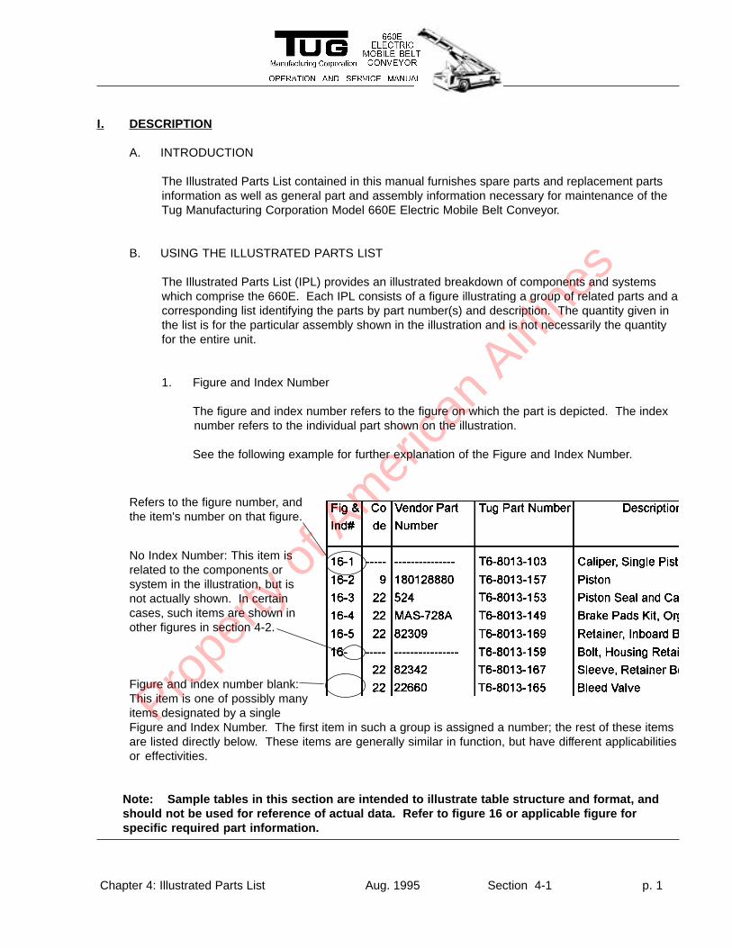
1. Figure and Index Number
The figure and index number refers to the figure on which the part is depicted. The indexnumber refers to the individual part shown on the illustration.
See the following example for further explanation of the Figure and Index Number.
Figure and index number blank:This item is one of possibly manyitems designated by a singleFigure and Index Number. The first item in such a group is assigned a number; the rest of these itemsare listed directly below. These items are generally similar in function, but have different applicabilitiesor effectivities.
Note: Sample tables in this section are intended to illustrate table structure and format, andshould not be used for reference of actual data. Refer to figure 16 or applicable figure forspecific required part information.
Refers to the figure number, andthe item's number on that figure.
No Index Number: This item isrelated to the components orsystem in the illustration, but isnot actually shown. In certaincases, such items are shown inother figures in section 4-2.
Prope
rty o
f Am
erica
n Airli
nes
Chapter 4: Illustrated Parts List Aug. 1995 Section 4-1 p. 2
I. DESCRIPTION
B. USING THE ILLUSTRATED PARTS LIST
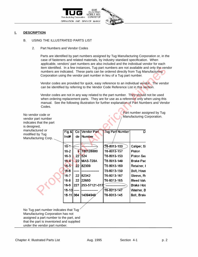
2. Part Numbers and Vendor Codes
Parts are identified by part numbers assigned by Tug Manufacturing Corporation or, in thecase of fasteners and related materials, by industry standard specification. Whenapplicable, vendors’ part numbers are also included and the individual vendor for eachitem identified. In a few instances, Tug part numbers are not available and only the vendornumbers are indicated. These parts can be ordered directly from Tug ManufacturingCorporation using the vendor part number in lieu of a Tug part number.
Vendor codes are provided for quick, easy reference to an individual vendor. The vendorcan be identified by referring to the Vendor Code Reference List in this section.
Vendor codes are not in any way related to the part number. They should not be usedwhen ordering replacement parts. They are for use as a reference only when using thismanual. See the following illustration for further explanation of Part Numbers and VendorCodes.
---------------
Part number assigned by TugManufacturing Corporation.No vendor code or
vendor part numberindicates that the partis designed,manufactured ormodified by TugManufacturing Corp.
No Tug part number indicates that TugManufacturing Corporation has notassigned a part number to the part, andthat the part is inventoried and suppliedunder the vendor part number.
Prope
rty o
f Am
erica
n Airli
nes
Chapter 4: Illustrated Parts List Aug. 1995 Section 4-1 p. 3
3. Description and Quantity
A description and quantity is provided for each part listed in the IPL. The quantity given forsubassemblies and sub-parts is the number of subassemblies/parts contained in thecomponent or system depicted by the associated illustration, not necessarily the entirevehicle.
4. Effectivity:
The effectivity of each item in the parts list is given in part or in whole in the “Effective”column of the IPL. Information concerning the effectivity of a particular part may also befound in the description column, the figure title or in notes located at the bottom of the IPLpage. Effectivity is usually (but not always) associated with the serial number.
C. ORDERING SPARE PARTS:
To ensure that proper spares and replacement parts are obtained, it is recommended that allmajor components be procured directly from Tug Manufacturing Corporation. Use of parts notmanufactured or supplied by Tug Manufacturing may void the warranty on the vehicle. Whenreplacing structural fasteners, use Grade 8 or higher material.
Spare parts can be ordered directly From Tug Manufacturing Corporation by telephoning TUGSHOP at 1-800-989-8499 (toll free in U.S. and Canada) or (U.S.A.) 404-422-7230 (outside U.S.or Canada). Ask for TUG SHOP when calling. FAX messages can be sent to (U.S.A.) 404-422-8730.
When ordering parts, please be prepared with Tug part numbers (vendor part number and code ifno Tug part number is available), part description, figure and index number and the revision dateof the IPL page (located in the center of the footer of each page, to the left of the page number).
TUG SHOP business hours are from 8:00 a.m. until 5:00 p.m. eastern time, Monday throughFriday. Answering machines are ready to receive calls after regular business hours. All callsreceived after hours will be returned during the next regular business day.
Prope
rty o
f Am
erica
n Airli
nes
Chapter 4: Illustrated Parts List Aug. 1995 Section 4-1 p. 4
(This Page Intentionally Left Blank)
Prope
rty o
f Am
erica
n Airli
nes
I. DESCRIPTION
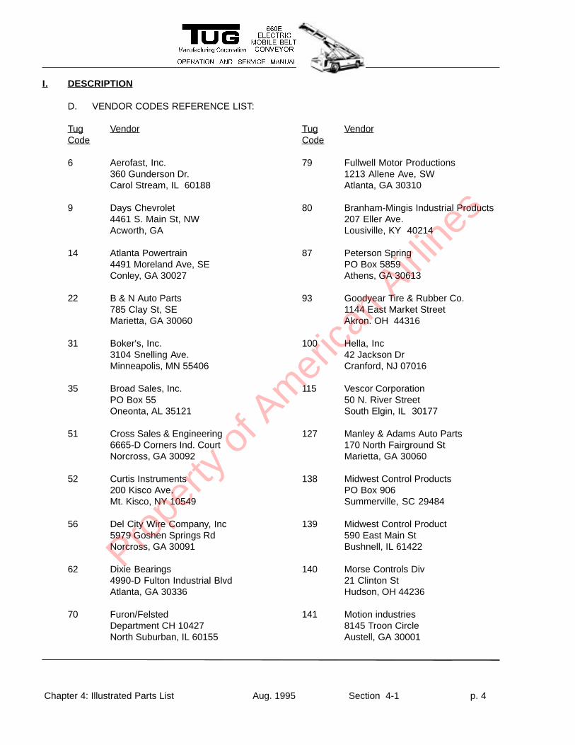
D. VENDOR CODES REFERENCE LIST:
Tug VendorCode
Tug VendorCode
Chapter 4: Illustrated Parts List Aug. 1995 Section 4-1 p. 4
6 Aerofast, Inc.360 Gunderson Dr.Carol Stream, IL 60188
9 Days Chevrolet4461 S. Main St, NWAcworth, GA
14 Atlanta Powertrain4491 Moreland Ave, SEConley, GA 30027
22 B & N Auto Parts785 Clay St, SEMarietta, GA 30060
31 Boker's, Inc.3104 Snelling Ave.Minneapolis, MN 55406
35 Broad Sales, Inc.PO Box 55Oneonta, AL 35121
51 Cross Sales & Engineering6665-D Corners Ind. CourtNorcross, GA 30092
52 Curtis Instruments200 Kisco Ave.Mt. Kisco, NY 10549
56 Del City Wire Company, Inc5979 Goshen Springs RdNorcross, GA 30091
62 Dixie Bearings4990-D Fulton Industrial BlvdAtlanta, GA 30336
70 Furon/FelstedDepartment CH 10427North Suburban, IL 60155
79 Fullwell Motor Productions1213 Allene Ave, SWAtlanta, GA 30310
80 Branham-Mingis Industrial Products207 Eller Ave.Lousiville, KY 40214
87 Peterson SpringPO Box 5859Athens, GA 30613
93 Goodyear Tire & Rubber Co.1144 East Market StreetAkron. OH 44316
100 Hella, Inc42 Jackson DrCranford, NJ 07016
115 Vescor Corporation50 N. River StreetSouth Elgin, IL 30177
127 Manley & Adams Auto Parts170 North Fairground StMarietta, GA 30060
138 Midwest Control ProductsPO Box 906Summerville, SC 29484
139 Midwest Control Product590 East Main StBushnell, IL 61422
140 Morse Controls Div21 Clinton StHudson, OH 44236
141 Motion industries8145 Troon CircleAustell, GA 30001
Prope
rty o
f Am
erica
n Airli
nes
Tug VendorCode
Tug VendorCode
Chapter 4: Illustrated Parts List Aug. 1995 Section 4-1 p. 5
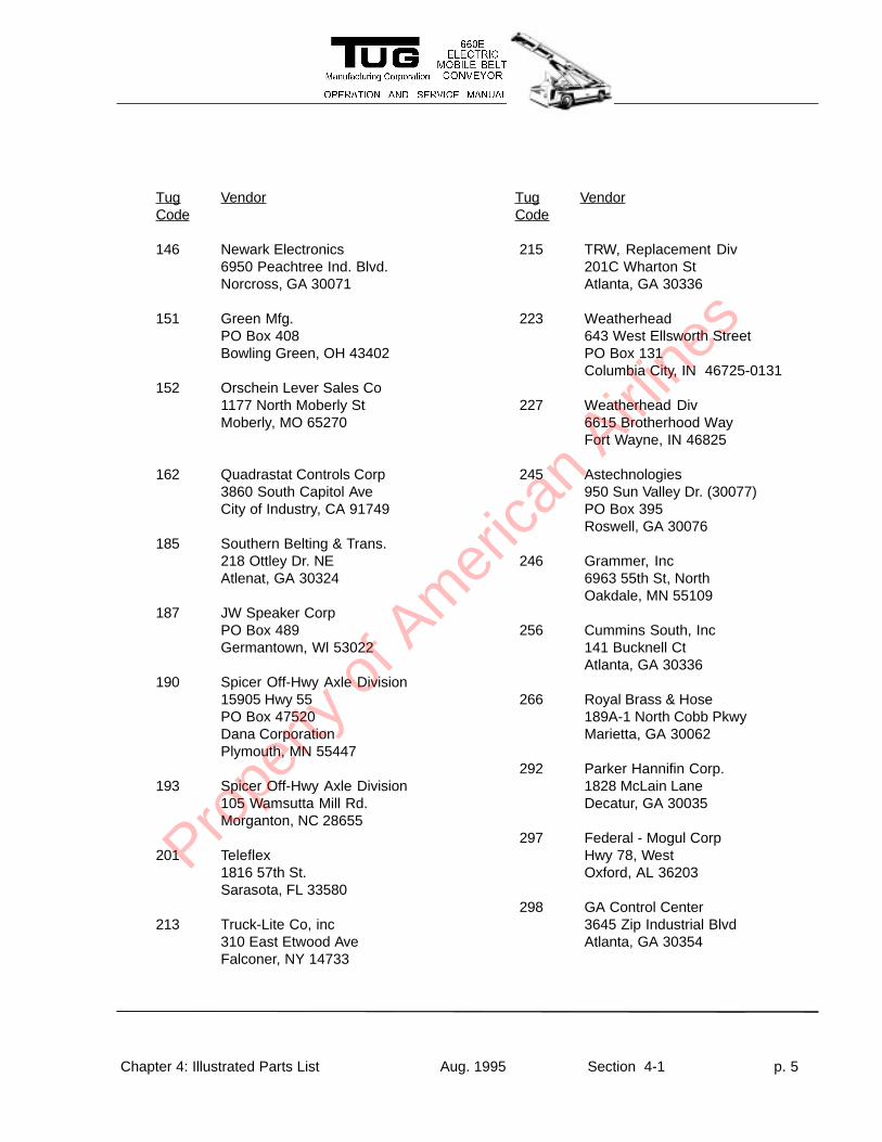
146 Newark Electronics6950 Peachtree Ind. Blvd.Norcross, GA 30071
151 Green Mfg.PO Box 408Bowling Green, OH 43402
152 Orschein Lever Sales Co1177 North Moberly StMoberly, MO 65270
162 Quadrastat Controls Corp3860 South Capitol AveCity of Industry, CA 91749
185 Southern Belting & Trans.218 Ottley Dr. NEAtlenat, GA 30324
187 JW Speaker CorpPO Box 489Germantown, Wl 53022
190 Spicer Off-Hwy Axle Division15905 Hwy 55PO Box 47520Dana CorporationPlymouth, MN 55447
193 Spicer Off-Hwy Axle Division105 Wamsutta Mill Rd.Morganton, NC 28655
201 Teleflex1816 57th St.Sarasota, FL 33580
213 Truck-Lite Co, inc310 East Etwood AveFalconer, NY 14733
215 TRW, Replacement Div201C Wharton StAtlanta, GA 30336
223 Weatherhead643 West Ellsworth StreetPO Box 131Columbia City, IN 46725-0131
227 Weatherhead Div6615 Brotherhood WayFort Wayne, IN 46825
245 Astechnologies950 Sun Valley Dr. (30077)PO Box 395Roswell, GA 30076
246 Grammer, Inc6963 55th St, NorthOakdale, MN 55109
256 Cummins South, Inc141 Bucknell CtAtlanta, GA 30336
266 Royal Brass & Hose189A-1 North Cobb PkwyMarietta, GA 30062
292 Parker Hannifin Corp.1828 McLain LaneDecatur, GA 30035
297 Federal - Mogul CorpHwy 78, WestOxford, AL 36203
298 GA Control Center3645 Zip Industrial BlvdAtlanta, GA 30354
Prope
rty o
f Am
erica
n Airli
nes
I. DESCRIPTION
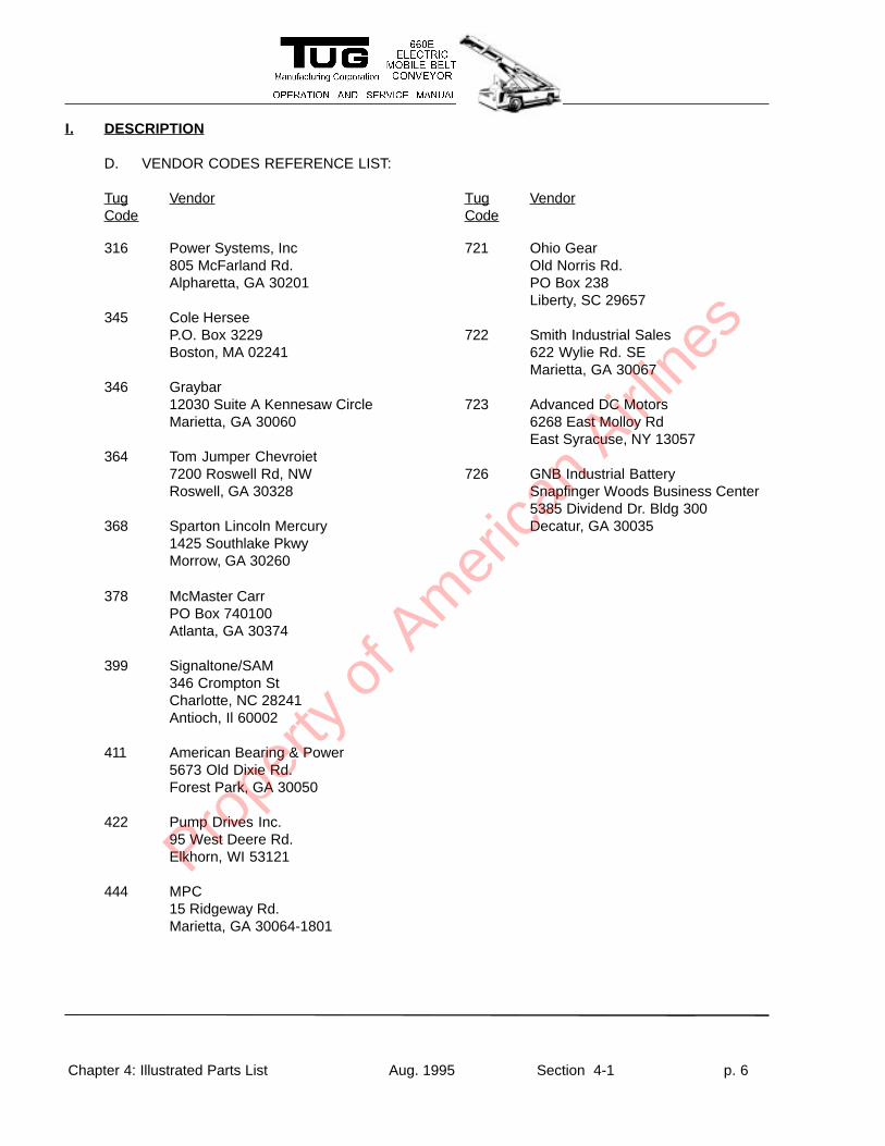
D. VENDOR CODES REFERENCE LIST:
Tug VendorCode
Tug VendorCode
Chapter 4: Illustrated Parts List Aug. 1995 Section 4-1 p. 6
316 Power Systems, Inc805 McFarland Rd.Alpharetta, GA 30201
345 Cole HerseeP.O. Box 3229Boston, MA 02241
346 Graybar12030 Suite A Kennesaw CircleMarietta, GA 30060
364 Tom Jumper Chevroiet7200 Roswell Rd, NWRoswell, GA 30328
368 Sparton Lincoln Mercury1425 Southlake PkwyMorrow, GA 30260
378 McMaster CarrPO Box 740100Atlanta, GA 30374
399 Signaltone/SAM346 Crompton StCharlotte, NC 28241Antioch, Il 60002
411 American Bearing & Power5673 Old Dixie Rd.Forest Park, GA 30050
422 Pump Drives Inc.95 West Deere Rd.Elkhorn, WI 53121
444 MPC15 Ridgeway Rd.Marietta, GA 30064-1801
721 Ohio GearOld Norris Rd.PO Box 238Liberty, SC 29657
722 Smith Industrial Sales622 Wylie Rd. SEMarietta, GA 30067
723 Advanced DC Motors6268 East Molloy RdEast Syracuse, NY 13057
726 GNB Industrial BatterySnapfinger Woods Business Center5385 Dividend Dr. Bldg 300Decatur, GA 30035
Prope
rty o
f Am
erica
n Airli
nes
Chapter 4: Illustrated Parts List Apr. 1996 Section 4-2 p. 1
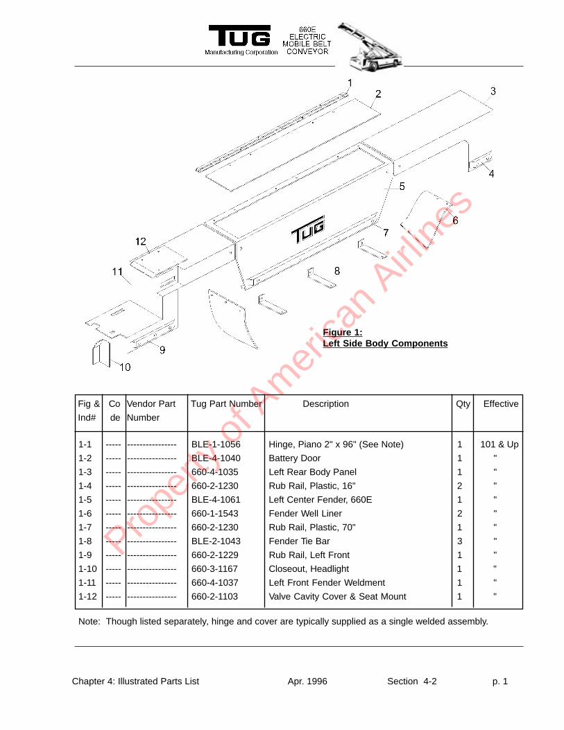
Figure 1:Left Side Body Components
Fig & Co Vendor Part Tug Part Number Description Qty Effective
Ind# de Number
1-1 ----- ---------------- BLE-1-1056 Hinge, Piano 2" x 96" (See Note) 1 101 & Up
1-2 ----- ---------------- BLE-4-1040 Battery Door 1 "
1-3 ----- ---------------- 660-4-1035 Left Rear Body Panel 1 "
1-4 ----- ---------------- 660-2-1230 Rub Rail, Plastic, 16" 2 "
1-5 ----- ---------------- BLE-4-1061 Left Center Fender, 660E 1 "
1-6 ----- ---------------- 660-1-1543 Fender Well Liner 2 "
1-7 ----- ---------------- 660-2-1230 Rub Rail, Plastic, 70" 1 "
1-8 ----- ---------------- BLE-2-1043 Fender Tie Bar 3 "
1-9 ----- ---------------- 660-2-1229 Rub Rail, Left Front 1 "
1-10 ----- ---------------- 660-3-1167 Closeout, Headlight 1 "
1-11 ----- ---------------- 660-4-1037 Left Front Fender Weldment 1 "
1-12 ----- ---------------- 660-2-1103 Valve Cavity Cover & Seat Mount 1 "
Note: Though listed separately, hinge and cover are typically supplied as a single welded assembly.
Prope
rty o
f Am
erica
n Airli
nes
Chapter 4: Illustrated Parts List Apr. 1996 Section 4-2 p. 2
Fig & Co Vendor Part Tug Part Number Description Qty Effective
Ind# de Number
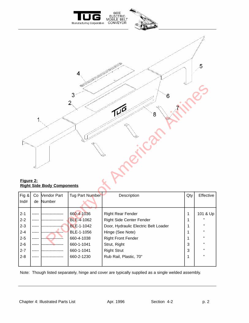
Figure 2:Right Side Body Components
2-1 ----- ---------------- 660-4-1036 Right Rear Fender 1 101 & Up
2-2 ----- ---------------- BLE-4-1062 Right Side Center Fender 1 "
2-3 ----- ---------------- BLE-1-1042 Door, Hydraulic Electric Belt Loader 1 "
2-4 ----- ---------------- BLE-1-1056 Hinge (See Note) 1 "
2-5 ----- ---------------- 660-4-1038 Right Front Fender 1 "
2-6 ----- ---------------- 660-1-1041 Strut, Right 3 "
2-7 ----- ---------------- 660-1-1041 Right Strut 3 "
2-8 ----- ---------------- 660-2-1230 Rub Rail, Plastic, 70" 1 "
Note: Though listed separately, hinge and cover are typically supplied as a single welded assembly.
Prope
rty o
f Am
erica
n Airli
nes
Chapter 4: Illustrated Parts List Apr. 1996 Section 4-2 p. 3
Fig & Co Vendor Part Tug Part Number Description Qty Effective
Ind# de Number
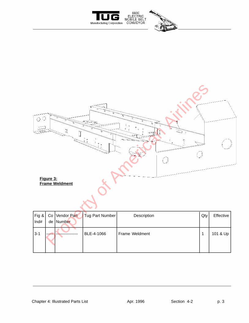
Figure 3:Frame Weldment
3-1 ----- ---------------- BLE-4-1066 Frame Weldment 1 101 & Up
Prope
rty o
f Am
erica
n Airli
nes
Chapter 4: Illustrated Parts List Apr. 1996 Section 4-2 p. 4
Fig & Co Vendor Part Tug Part Number Description Qty Effective
Ind# de Number
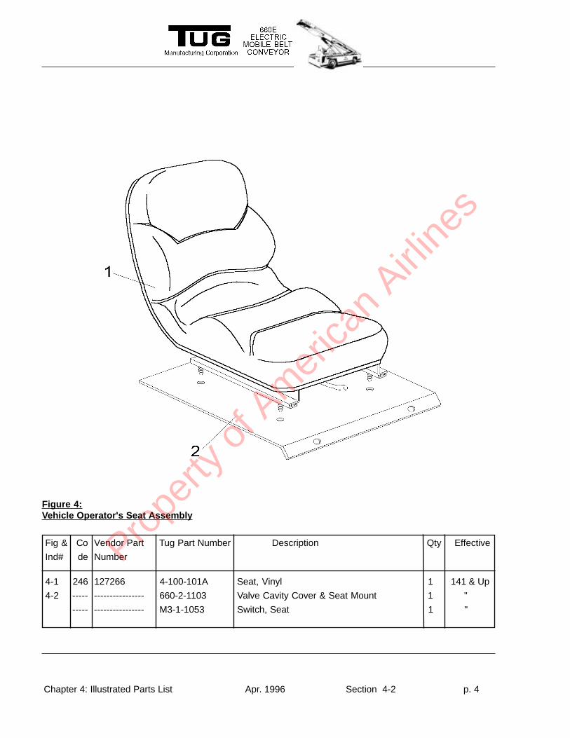
Figure 4:Vehicle Operator's Seat Assembly
4-1 246 127266 4-100-101A Seat, Vinyl 1 141 & Up
4-2 ----- ---------------- 660-2-1103 Valve Cavity Cover & Seat Mount 1 "
----- ---------------- M3-1-1053 Switch, Seat 1 "
Prope
rty o
f Am
erica
n Airli
nes
Chapter 4: Illustrated Parts List Apr. 1996 Section 4-2 p. 5
Fig & Co Vendor Part Tug Part Number Description Qty Effective
Ind# de Number
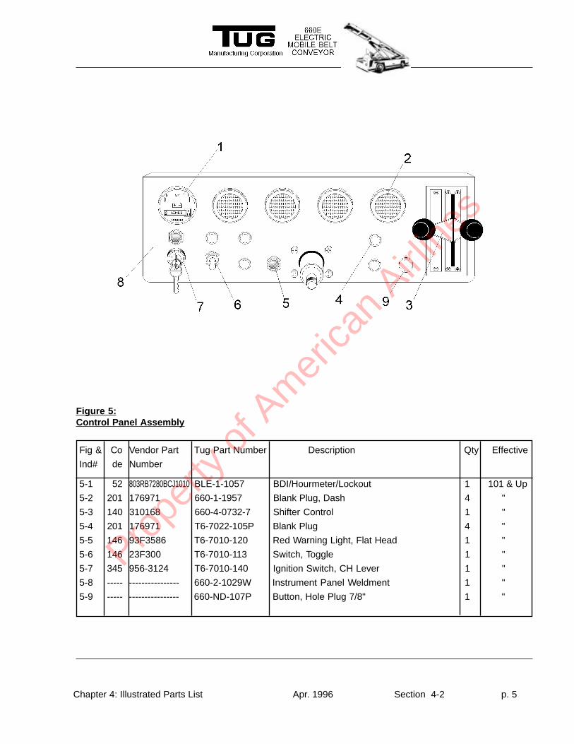
Figure 5:Control Panel Assembly
5-1 52 803RB7280BCJ1010 BLE-1-1057 BDI/Hourmeter/Lockout 1 101 & Up
5-2 201 176971 660-1-1957 Blank Plug, Dash 4 "
5-3 140 310168 660-4-0732-7 Shifter Control 1 "
5-4 201 176971 T6-7022-105P Blank Plug 4 "
5-5 146 93F3586 T6-7010-120 Red Warning Light, Flat Head 1 "
5-6 146 23F300 T6-7010-113 Switch, Toggle 1 "
5-7 345 956-3124 T6-7010-140 Ignition Switch, CH Lever 1 "
5-8 ----- ---------------- 660-2-1029W Instrument Panel Weldment 1 "
5-9 ----- ---------------- 660-ND-107P Button, Hole Plug 7/8" 1 "
Prope
rty o
f Am
erica
n Airli
nes
Chapter 4: Illustrated Parts List Apr. 1996 Section 4-2 p. 6
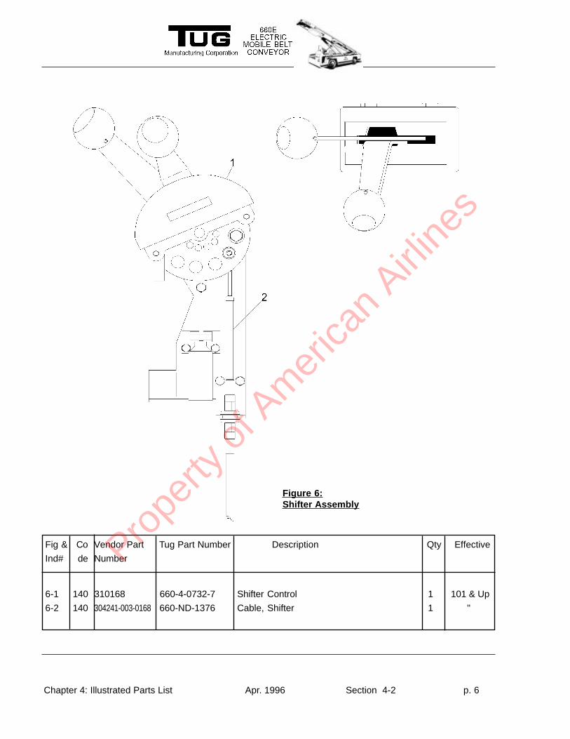
Figure 6:Shifter Assembly
Fig & Co Vendor Part Tug Part Number Description Qty Effective
Ind# de Number
6-1 140 310168 660-4-0732-7 Shifter Control 1 101 & Up
6-2 140 304241-003-0168 660-ND-1376 Cable, Shifter 1 "
Prope
rty o
f Am
erica
n Airli
nes
Chapter 4: Illustrated Parts List Apr. 1996 Section 4-2 p. 7
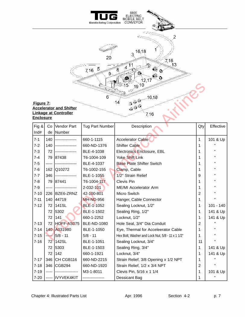
Fig & Co Vendor Part Tug Part Number Description Qty Effective
Ind# de Number
Figure 7:Accelerator and ShifterLinkage at ControllerEnclosure
7-1 140 ---------------- 660-1-1115 Accelerator Cable 1 101 & Up
7-2 140 ---------------- 660-ND-1376 Shifter Cable 1 "
7-3 72 ---------------- BLE-4-1038 Electronics Enclosure, EBL 1 "
7-4 79 87438 T6-1004-109 Yoke Shift Link 1 "
7-5 ----- ---------------- BLE-4-1037 Base Plate Shifter Switch 1 "
7-6 162 Q10272 T6-1002-155 Clamp, Cable 1 "
7-7 346 ---------------- BLE-1-1055 1/2" Strain Relief 9 "
7-8 79 87441 T6-1004-117 Clevis Pin 1 "
7-9 ----- ---------------- 2-032-101 ME/MI Accelerator Arm 1 "
7-10 226 BZE6-ZRNZ 42-100-801 Micro Switch 2 "
7-11 140 44719 MH-ND-956 Hanger, Cable Connector 1 "
7-12 72 141SL BLE-1-1052 Sealing Locknut, 1/2" 1 101 - 140
72 5302 BLE-1-1502 Sealing Ring, 1/2" 1 141 & Up
72 141 660-1-2252 Locknut, 1/2" 1 141 & Up
7-13 72 HOFF-AS075 BLE-ND-1080 Hole Seal, 3/4" Dia Conduit 2 "
7-14 140 A031980 BLE-1-1050 Eye, Thermal for Acceleerator Cable 1 "
7-15 ----- 5/8 - 11 5/8 - 11 Hex Bolt, Washer and Lock Nut, 5/8 - 11 x 1 1/2" 1 "
7-16 72 142SL BLE-1-1051 Sealing Locknut, 3/4" 11 "
72 5303 BLE-1-1503 Sealing Ring, 3/4" 1 141 & Up
72 142 660-1-1921 Locknut, 3/4" 1 141 & Up
7-17 346 CH CGB116 660-ND-2215 Strain Relief, 3/8 Opening x 1/2 NPT 1 "
7-18 346 CGB294 660-ND-1920 Strain Relief, 1/2 x 3/4 NPT 2 "
7-19 ----- ----------------- M3-1-8011 Clevis Pin, 5/16 x 1 1/4 1 101 & Up
7-20 ----- IVYVEK4KIT ---------------- Dessicant Bag 1 "
Prope
rty o
f Am
erica
n Airli
nes
Chapter 4: Illustrated Parts List Apr. 1996 Section 4-2 p. 8
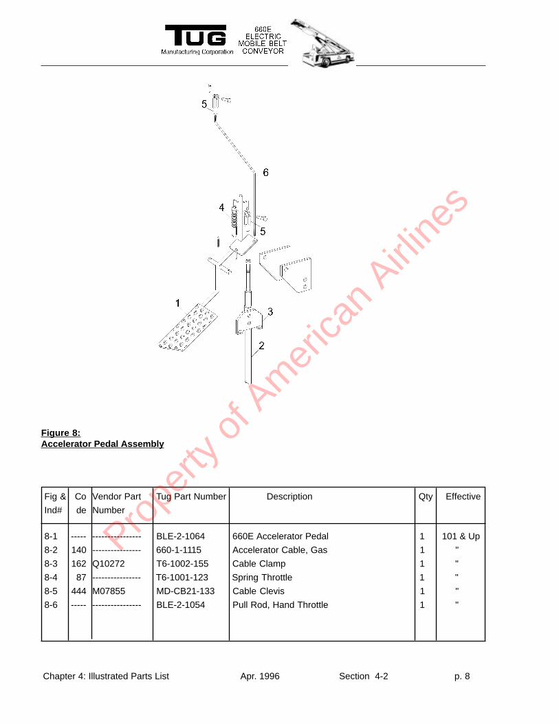
Fig & Co Vendor Part Tug Part Number Description Qty Effective
Ind# de Number
8-1 ----- ---------------- BLE-2-1064 660E Accelerator Pedal 1 101 & Up
8-2 140 ---------------- 660-1-1115 Accelerator Cable, Gas 1 "
8-3 162 Q10272 T6-1002-155 Cable Clamp 1 "
8-4 87 ---------------- T6-1001-123 Spring Throttle 1 "
8-5 444 M07855 MD-CB21-133 Cable Clevis 1 "
8-6 ----- ---------------- BLE-2-1054 Pull Rod, Hand Throttle 1 "
Figure 8:Accelerator Pedal Assembly
Prope
rty o
f Am
erica
n Airli
nes
Chapter 4: Illustrated Parts List Apr. 1996 Section 4-2 p. 9
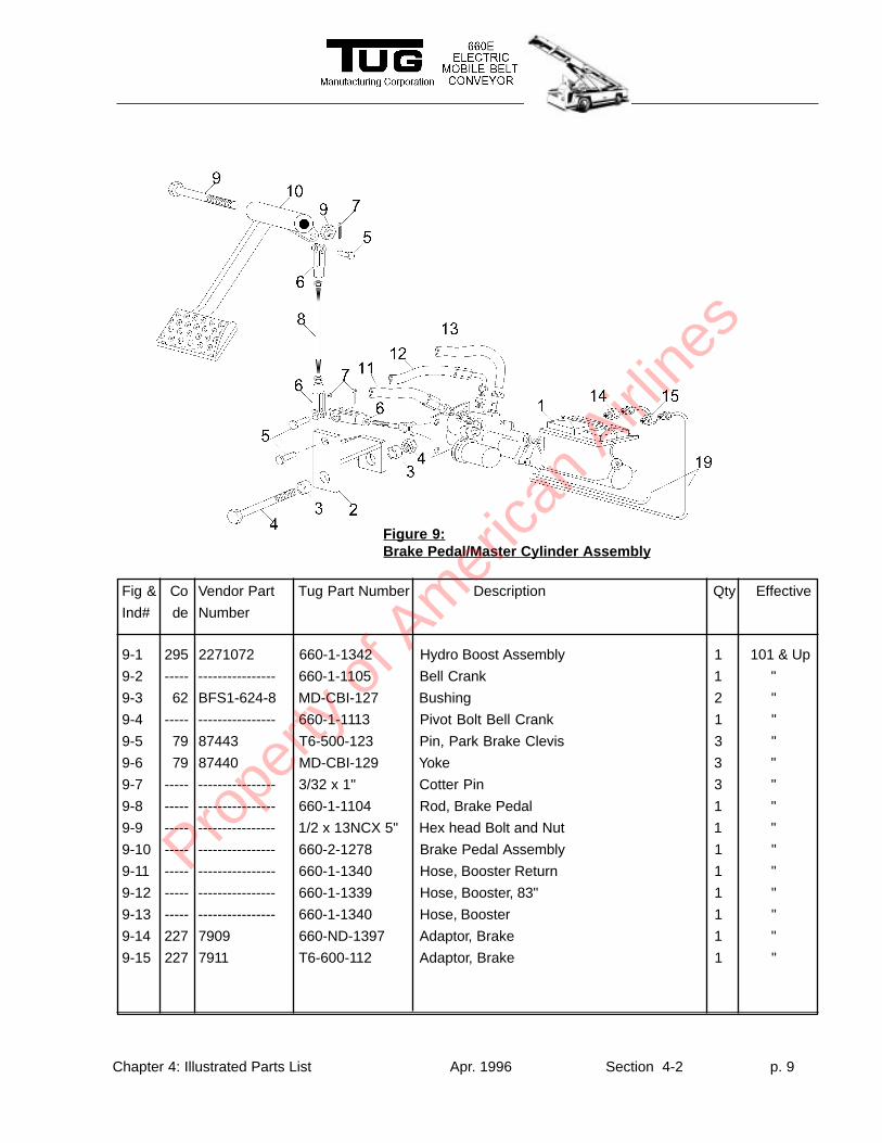
Figure 9:Brake Pedal/Master Cylinder Assembly
Fig & Co Vendor Part Tug Part Number Description Qty Effective
Ind# de Number
9-1 295 2271072 660-1-1342 Hydro Boost Assembly 1 101 & Up
9-2 ----- ---------------- 660-1-1105 Bell Crank 1 "
9-3 62 BFS1-624-8 MD-CBI-127 Bushing 2 "
9-4 ----- ---------------- 660-1-1113 Pivot Bolt Bell Crank 1 "
9-5 79 87443 T6-500-123 Pin, Park Brake Clevis 3 "
9-6 79 87440 MD-CBI-129 Yoke 3 "
9-7 ----- ---------------- 3/32 x 1" Cotter Pin 3 "
9-8 ----- ---------------- 660-1-1104 Rod, Brake Pedal 1 "
9-9 ----- ---------------- 1/2 x 13NCX 5" Hex head Bolt and Nut 1 "
9-10 ----- ---------------- 660-2-1278 Brake Pedal Assembly 1 "
9-11 ----- ---------------- 660-1-1340 Hose, Booster Return 1 "
9-12 ----- ---------------- 660-1-1339 Hose, Booster, 83" 1 "
9-13 ----- ---------------- 660-1-1340 Hose, Booster 1 "
9-14 227 7909 660-ND-1397 Adaptor, Brake 1 "
9-15 227 7911 T6-600-112 Adaptor, Brake 1 "
Prope
rty o
f Am
erica
n Airli
nes
Chapter 4: Illustrated Parts List Apr. 1996 Section 4-2 p. 10
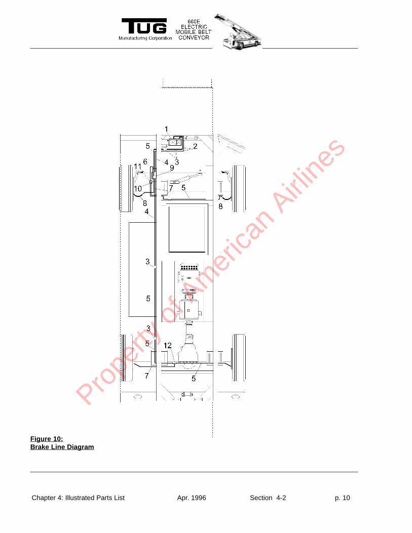
Figure 10:Brake Line Diagram
Prope
rty o
f Am
erica
n Airli
nes
Chapter 4: Illustrated Parts List Apr. 1996 Section 4-2 p. 11
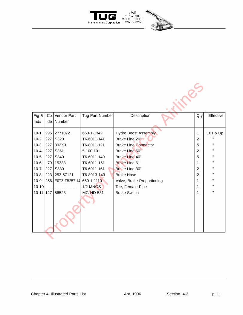
Fig & Co Vendor Part Tug Part Number Description Qty Effective
Ind# de Number
10-1 295 2771072 660-1-1342 Hydro Boost Assembly 1 101 & Up
10-2 227 S320 T6-6011-141 Brake Line 20" 2 "
10-3 227 302X3 T6-8011-121 Brake Line Connector 5 "
10-4 227 S351 5-100-101 Brake Line 50" 2 "
10-5 227 S340 T6-6011-149 Brake Line 40" 5 "
10-6 79 15333 T6-6011-151 Brake Line 6" 1 "
10-7 227 S330 T6-6011-161 Brake Line 30" 2 "
10-8 223 253-57121 T6-8013-143 Brake Hose 2 "
10-9 256 E0TZ-ZB257-14 660-1-1110 Valve, Brake Proportioning 1 "
10-10 ----- ---------------- 1/2 MNOS Tee, Female Pipe 1 "
10-11 127 56523 MG-ND-531 Brake Switch 1 "
Prope
rty o
f Am
erica
n Airli
nes
Chapter 4: Illustrated Parts List Apr. 1996 Section 4-2 p. 12
Fig & Co Vendor Part Tug Part Number Description Qty Effective
Ind# de Number
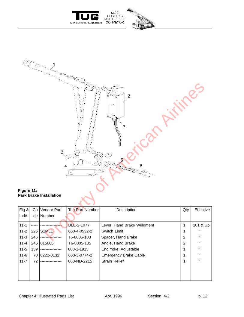
11-1 ----- ---------------- BLE-2-1077 Lever, Hand Brake Weldment 1 101 & Up
11-2 226 S1ML1 660-4-0532-2 Switch Limit 1 "
11-3 245 ---------------- T6-8005-103 Spacer, Hand Brake 2 "
11-4 245 015666 T6-8005-105 Angle, Hand Brake 2 "
11-5 139 ---------------- 660-1-1913 End Yoke, Adjustable 1 "
11-6 70 6222-0132 660-3-0774-2 Emergency Brake Cable 1 "
11-7 72 ---------------- 660-ND-2215 Strain Relief 1 "
Figure 1 1:Park Brake Installation
Prope
rty o
f Am
erica
n Airli
nes
Chapter 4: Illustrated Parts List Apr. 1996 Section 4-2 p. 13
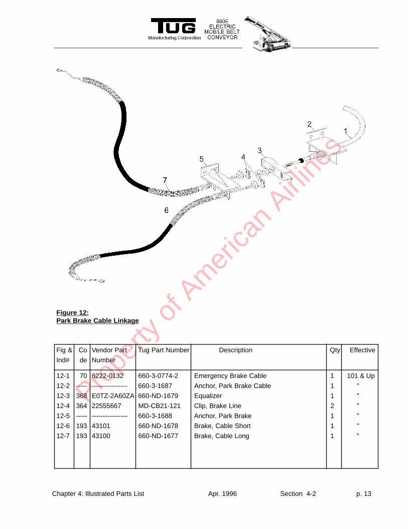
Fig & Co Vendor Part Tug Part Number Description Qty Effective
Ind# de Number
12-1 70 6222-0132 660-3-0774-2 Emergency Brake Cable 1 101 & Up
12-2 ----- ---------------- 660-3-1687 Anchor, Park Brake Cable 1 "
12-3 368 E0TZ-2A60ZA 660-ND-1679 Equalizer 1 "
12-4 364 22555667 MD-CB21-121 Clip, Brake Line 2 "
12-5 ----- ---------------- 660-3-1688 Anchor, Park Brake 1 "
12-6 193 43101 660-ND-1678 Brake, Cable Short 1 "
12-7 193 43100 660-ND-1677 Brake, Cable Long 1 "
Figure 12:Park Brake Cable Linkage
Prope
rty o
f Am
erica
n Airli
nes
Chapter 4: Illustrated Parts List Apr. 1996 Section 4-2 p. 14
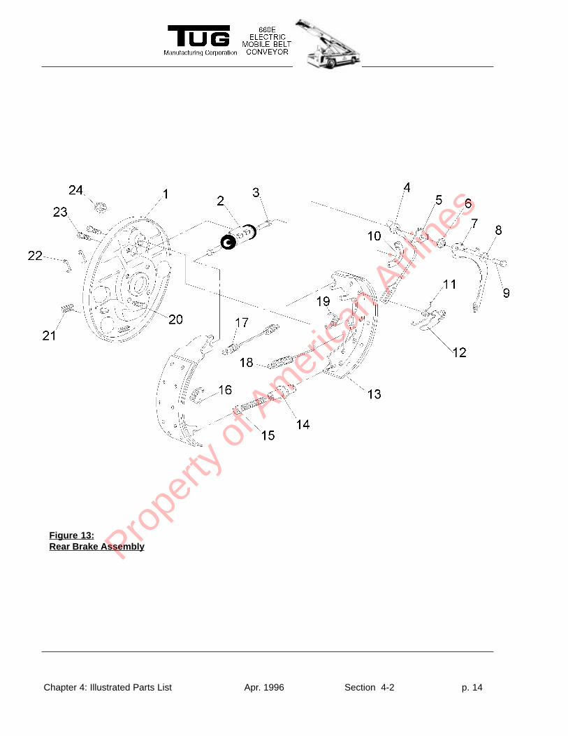
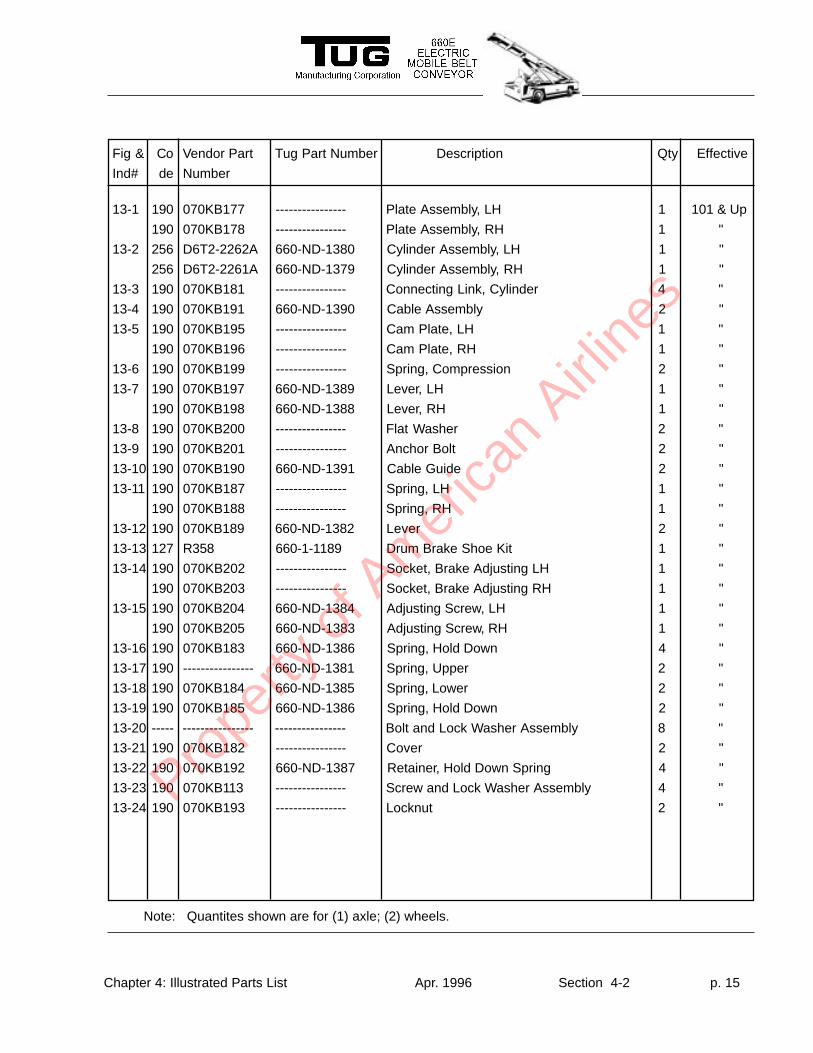
Figure 13:Rear Brake AssemblyPro
perty
of A
mer
ican
Airline
s
Chapter 4: Illustrated Parts List Apr. 1996 Section 4-2 p. 15
Fig & Co Vendor Part Tug Part Number Description Qty Effective
Ind# de Number
13-1 190 070KB177 ---------------- Plate Assembly, LH 1 101 & Up
190 070KB178 ---------------- Plate Assembly, RH 1 "
13-2 256 D6T2-2262A 660-ND-1380 Cylinder Assembly, LH 1 "
256 D6T2-2261A 660-ND-1379 Cylinder Assembly, RH 1 "
13-3 190 070KB181 ---------------- Connecting Link, Cylinder 4 "
13-4 190 070KB191 660-ND-1390 Cable Assembly 2 "
13-5 190 070KB195 ---------------- Cam Plate, LH 1 "
190 070KB196 ---------------- Cam Plate, RH 1 "
13-6 190 070KB199 ---------------- Spring, Compression 2 "
13-7 190 070KB197 660-ND-1389 Lever, LH 1 "
190 070KB198 660-ND-1388 Lever, RH 1 "
13-8 190 070KB200 ---------------- Flat Washer 2 "
13-9 190 070KB201 ---------------- Anchor Bolt 2 "
13-10 190 070KB190 660-ND-1391 Cable Guide 2 "
13-11 190 070KB187 ---------------- Spring, LH 1 "
190 070KB188 ---------------- Spring, RH 1 "
13-12 190 070KB189 660-ND-1382 Lever 2 "
13-13 127 R358 660-1-1189 Drum Brake Shoe Kit 1 "
13-14 190 070KB202 ---------------- Socket, Brake Adjusting LH 1 "
190 070KB203 ---------------- Socket, Brake Adjusting RH 1 "
13-15 190 070KB204 660-ND-1384 Adjusting Screw, LH 1 "
190 070KB205 660-ND-1383 Adjusting Screw, RH 1 "
13-16 190 070KB183 660-ND-1386 Spring, Hold Down 4 "
13-17 190 ---------------- 660-ND-1381 Spring, Upper 2 "
13-18 190 070KB184 660-ND-1385 Spring, Lower 2 "
13-19 190 070KB185 660-ND-1386 Spring, Hold Down 2 "
13-20 ----- ---------------- ---------------- Bolt and Lock Washer Assembly 8 "
13-21 190 070KB182 ---------------- Cover 2 "
13-22 190 070KB192 660-ND-1387 Retainer, Hold Down Spring 4 "
13-23 190 070KB113 ---------------- Screw and Lock Washer Assembly 4 "
13-24 190 070KB193 ---------------- Locknut 2 "
Note: Quantites shown are for (1) axle; (2) wheels.
Prope
rty o
f Am
erica
n Airli
nes
Chapter 4: Illustrated Parts List Apr. 1996 Section 4-2 p. 16
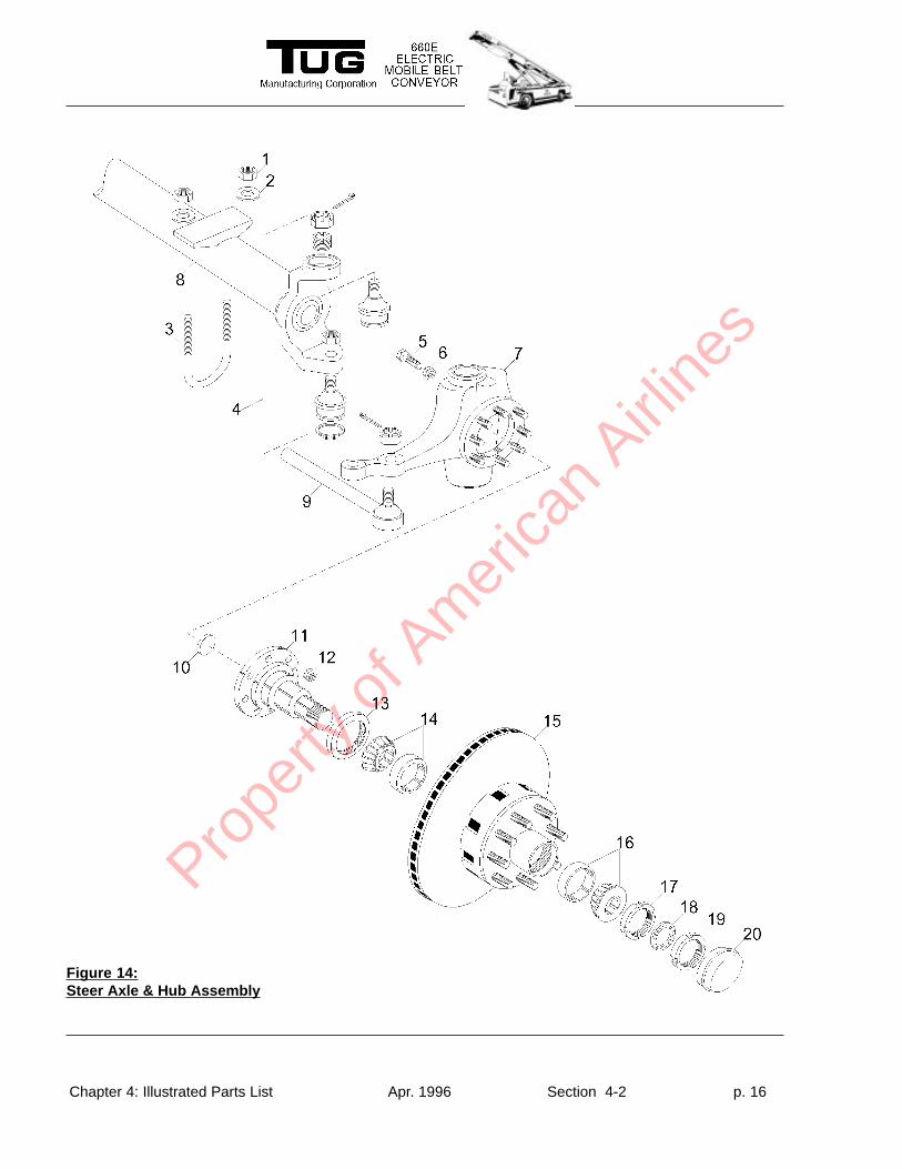
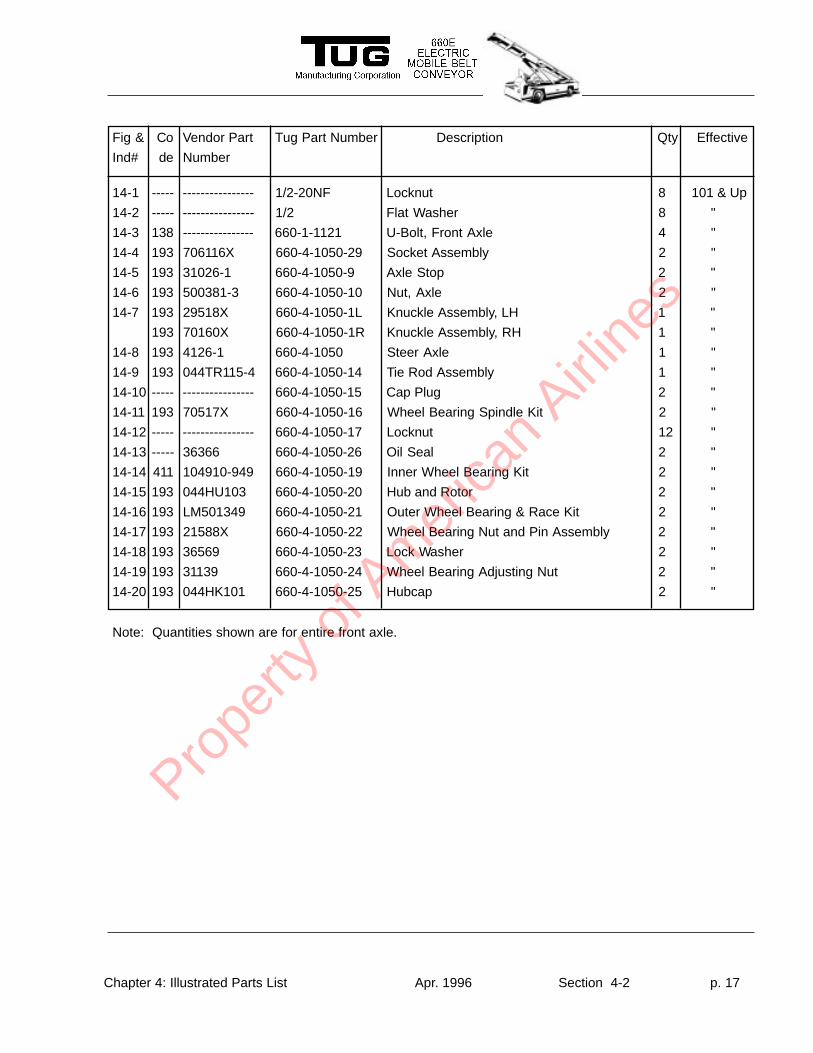
Figure 14:Steer Axle & Hub Assembly
Prope
rty o
f Am
erica
n Airli
nes
Chapter 4: Illustrated Parts List Apr. 1996 Section 4-2 p. 17
Fig & Co Vendor Part Tug Part Number Description Qty Effective
Ind# de Number
Note: Quantities shown are for entire front axle.
14-1 ----- ---------------- 1/2-20NF Locknut 8 101 & Up
14-2 ----- ---------------- 1/2 Flat Washer 8 "
14-3 138 ---------------- 660-1-1121 U-Bolt, Front Axle 4 "
14-4 193 706116X 660-4-1050-29 Socket Assembly 2 "
14-5 193 31026-1 660-4-1050-9 Axle Stop 2 "
14-6 193 500381-3 660-4-1050-10 Nut, Axle 2 "
14-7 193 29518X 660-4-1050-1L Knuckle Assembly, LH 1 "
193 70160X 660-4-1050-1R Knuckle Assembly, RH 1 "
14-8 193 4126-1 660-4-1050 Steer Axle 1 "
14-9 193 044TR115-4 660-4-1050-14 Tie Rod Assembly 1 "
14-10 ----- ---------------- 660-4-1050-15 Cap Plug 2 "
14-11 193 70517X 660-4-1050-16 Wheel Bearing Spindle Kit 2 "
14-12 ----- ---------------- 660-4-1050-17 Locknut 12 "
14-13 ----- 36366 660-4-1050-26 Oil Seal 2 "
14-14 411 104910-949 660-4-1050-19 Inner Wheel Bearing Kit 2 "
14-15 193 044HU103 660-4-1050-20 Hub and Rotor 2 "
14-16 193 LM501349 660-4-1050-21 Outer Wheel Bearing & Race Kit 2 "
14-17 193 21588X 660-4-1050-22 Wheel Bearing Nut and Pin Assembly 2 "
14-18 193 36569 660-4-1050-23 Lock Washer 2 "
14-19 193 31139 660-4-1050-24 Wheel Bearing Adjusting Nut 2 "
14-20 193 044HK101 660-4-1050-25 Hubcap 2 "
Prope
rty o
f Am
erica
n Airli
nes
Chapter 4: Illustrated Parts List Apr. 1996 Section 4-2 p. 18
Fig & Co Vendor Part Tug Part Number Description Qty Effective
Ind# de Number
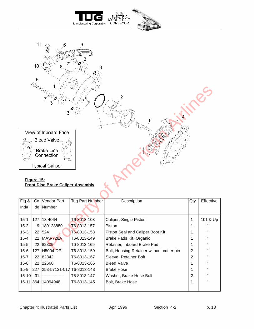
15-1 127 18-4064 T6-8013-103 Caliper, Single Piston 1 101 & Up
15-2 9 180128880 T6-8013-157 Piston 1 "
15-3 22 524 T6-8013-153 Piston Seal and Caliper Boot Kit 1 "
15-4 22 MAS-728A T6-8013-149 Brake Pads Kit, Organic 1 "
15-5 22 82309 T6-8013-169 Retainer, Inboard Brake Pad 1 "
15-6 127 H5004-DP T6-8013-159 Bolt, Housing Retainer without cotter pin 2 "
15-7 22 82342 T6-8013-167 Sleeve, Retainer Bolt 2 "
15-8 22 22660 T6-8013-165 Bleed Valve 1 "
15-9 227 253-57121-017 T6-8013-143 Brake Hose 1 "
15-10 31 ---------------- T6-8013-147 Washer, Brake Hose Bolt 2 "
15-11 364 14094948 T6-8013-145 Bolt, Brake Hose 1 "
Figure 15:Front Disc Brake Caliper Assembly
Prope
rty o
f Am
erica
n Airli
nes
Chapter 4: Illustrated Parts List Apr. 1996 Section 4-2 p. 19
Fig & Co Vendor Part Tug Part Number Description Qty Effective
Ind# de Number
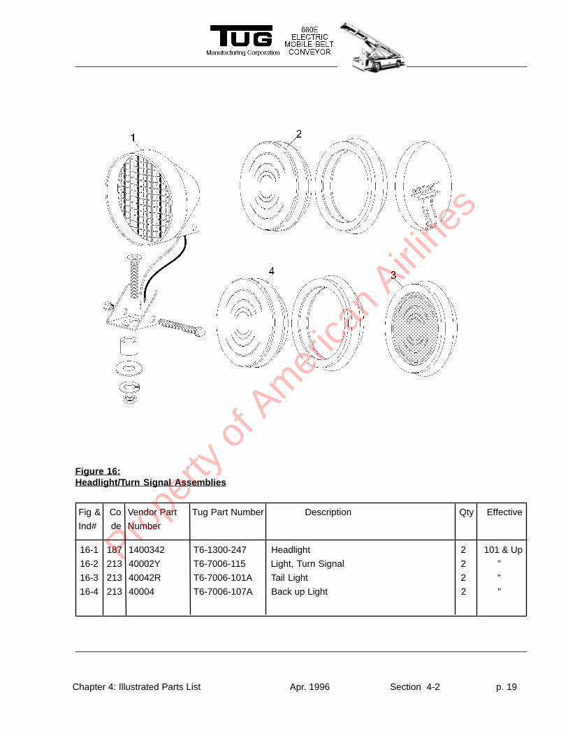
Figure 16:Headlight/T urn Signal Assemblies
16-1 187 1400342 T6-1300-247 Headlight 2 101 & Up
16-2 213 40002Y T6-7006-115 Light, Turn Signal 2 "
16-3 213 40042R T6-7006-101A Tail Light 2 "
16-4 213 40004 T6-7006-107A Back up Light 2 "
Prope
rty o
f Am
erica
n Airli
nes
Chapter 4: Illustrated Parts List Apr. 1996 Section 4-2 p. 20
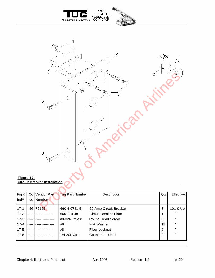
17-1 56 72125 660-4-0741-5 20 Amp Circuit Breaker 3 101 & Up
17-2 ----- ---------------- 660-1-1048 Circuit Breaker Plate 1 "
17-3 ----- ---------------- #8-32NCx5/8" Round Head Screw 6 "
17-4 ----- ---------------- #8 Flat Washer 12 "
17-5 ----- ---------------- #8 Fiber Locknut 6 "
17-6 ----- ---------------- 1/4-20NCx1" Countersunk Bolt 2 "
Fig & Co Vendor Part Tug Part Number Description Qty Effective
Ind# de Number
Figure 17:Circuit Breaker Installation
Prope
rty o
f Am
erica
n Airli
nes
Chapter 4: Illustrated Parts List Apr. 1996 Section 4-2 p. 21
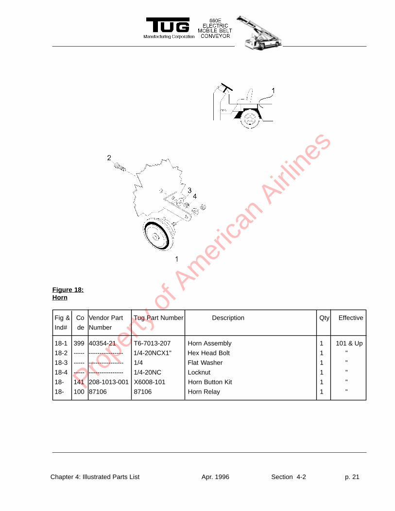
Figure 18:Horn
Fig & Co Vendor Part Tug Part Number Description Qty Effective
Ind# de Number
18-1 399 40354-21 T6-7013-207 Horn Assembly 1 101 & Up
18-2 ----- ---------------- 1/4-20NCX1" Hex Head Bolt 1 "
18-3 ----- ---------------- 1/4 Flat Washer 1 "
18-4 ----- ---------------- 1/4-20NC Locknut 1 "
18- 141 208-1013-001 X6008-101 Horn Button Kit 1 "
18- 100 87106 87106 Horn Relay 1 "Prope
rty o
f Am
erica
n Airli
nes
Chapter 4: Illustrated Parts List Apr. 1996 Section 4-2 p. 22
Fig & Co Vendor Part Tug Part Number Description Qty Effective
Ind# de Number
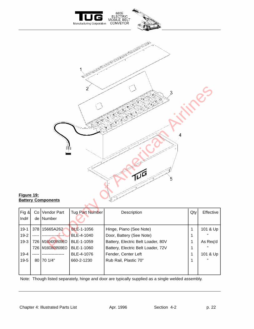
Figure 19:Battery Components
19-1 378 15665A262 BLE-1-1056 Hinge, Piano (See Note) 1 101 & Up
19-2 ----- ---------------- BLE-4-1040 Door, Battery (See Note) 1 "
19-3 726 M1604009509EO BLE-1-1059 Battery, Electric Belt Loader, 80V 1 As Req'd
726 M1603609509EO BLE-1-1060 Battery, Electric Belt Loader, 72V 1 "
19-4 ----- ---------------- BLE-4-1076 Fender, Center Left 1 101 & Up
19-5 80 70 1/4" 660-2-1230 Rub Rail, Plastic 70" 1 "
Note: Though listed separately, hinge and door are typically supplied as a single welded assembly.
Prope
rty o
f Am
erica
n Airli
nes
Chapter 4: Illustrated Parts List Apr. 1996 Section 4-2 p. 23
Fig & Co Vendor Part Tug Part Number Description Qty Effective
Ind# de Number
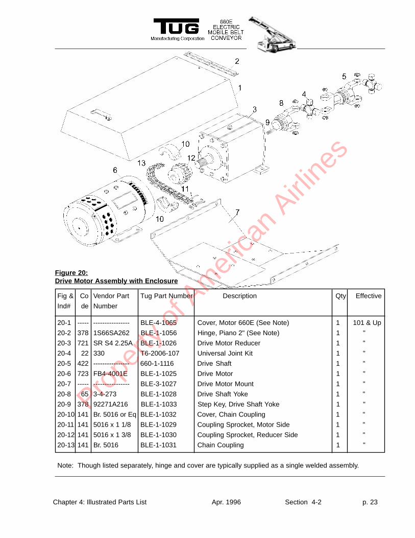
20-1 ----- ---------------- BLE-4-1065 Cover, Motor 660E (See Note) 1 101 & Up
20-2 378 1S66SA262 BLE-1-1056 Hinge, Piano 2" (See Note) 1 "
20-3 721 SR S4 2.25A BLE-1-1026 Drive Motor Reducer 1 "
20-4 22 330 T6-2006-107 Universal Joint Kit 1 "
20-5 422 ---------------- 660-1-1116 Drive Shaft 1 "
20-6 723 FB4-4001E BLE-1-1025 Drive Motor 1 "
20-7 ----- ---------------- BLE-3-1027 Drive Motor Mount 1 "
20-8 65 3-4-273 BLE-1-1028 Drive Shaft Yoke 1 "
20-9 378 92271A216 BLE-1-1033 Step Key, Drive Shaft Yoke 1 "
20-10 141 Br. 5016 or Eq BLE-1-1032 Cover, Chain Coupling 1 "
20-11 141 5016 x 1 1/8 BLE-1-1029 Coupling Sprocket, Motor Side 1 "
20-12 141 5016 x 1 3/8 BLE-1-1030 Coupling Sprocket, Reducer Side 1 "
20-13 141 Br. 5016 BLE-1-1031 Chain Coupling 1 "
Note: Though listed separately, hinge and cover are typically supplied as a single welded assembly.
Figure 20:Drive Motor Assembly with Enclosure
Prope
rty o
f Am
erica
n Airli
nes
Chapter 4: Illustrated Parts List Apr. 1996 Section 4-2 p. 24
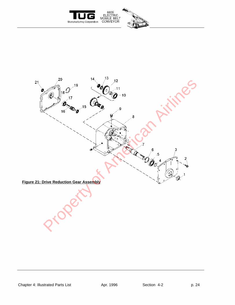
Figure 21: Drive Reduction Gear Assembly
Prope
rty o
f Am
erica
n Airli
nes
Chapter 4: Illustrated Parts List Apr. 1996 Section 4-2 p. 25
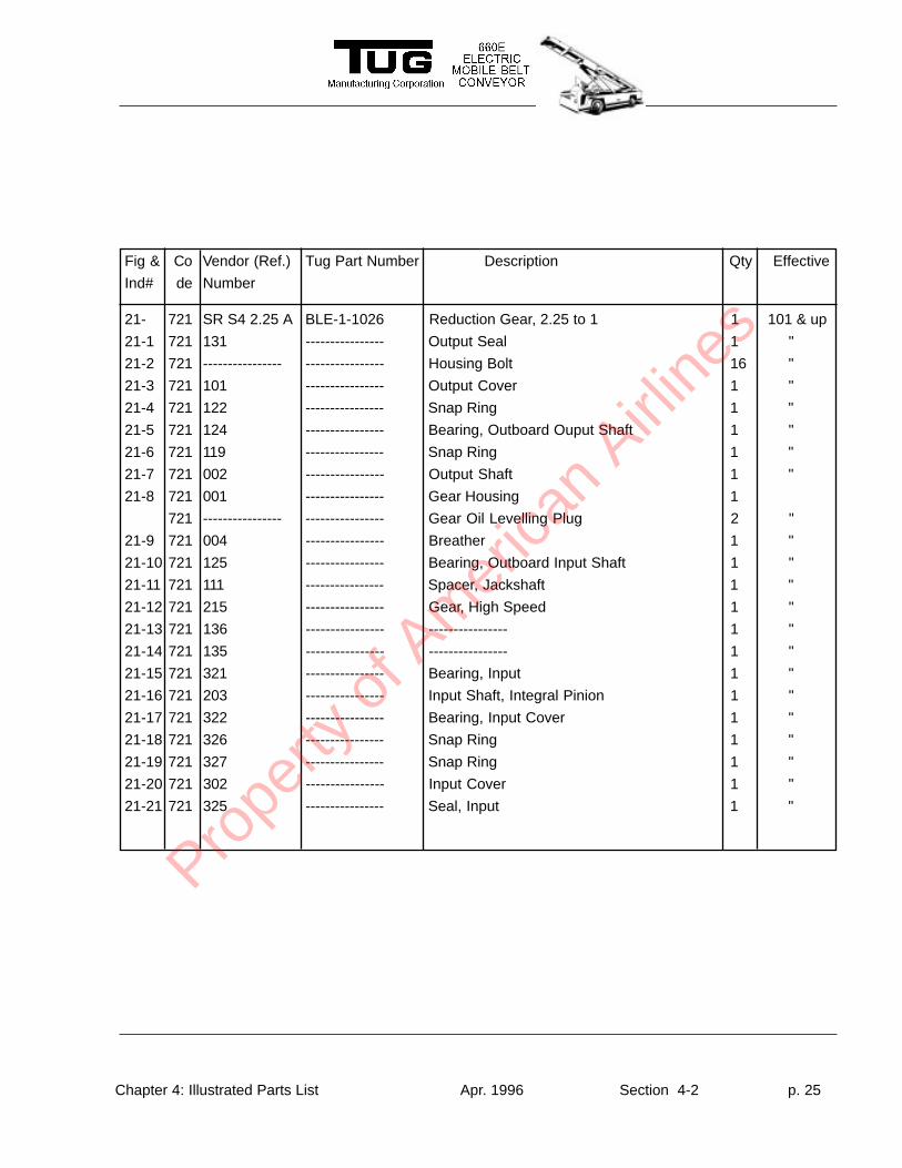
Fig & Co Vendor (Ref.) Tug Part Number Description Qty Effective
Ind# de Number
21- 721 SR S4 2.25 A BLE-1-1026 Reduction Gear, 2.25 to 1 1 101 & up
21-1 721 131 ---------------- Output Seal 1 "
21-2 721 ---------------- ---------------- Housing Bolt 16 "
21-3 721 101 ---------------- Output Cover 1 "
21-4 721 122 ---------------- Snap Ring 1 "
21-5 721 124 ---------------- Bearing, Outboard Ouput Shaft 1 "
21-6 721 119 ---------------- Snap Ring 1 "
21-7 721 002 ---------------- Output Shaft 1 "
21-8 721 001 ---------------- Gear Housing 1
721 ---------------- ---------------- Gear Oil Levelling Plug 2 "
21-9 721 004 ---------------- Breather 1 "
21-10 721 125 ---------------- Bearing, Outboard Input Shaft 1 "
21-11 721 111 ---------------- Spacer, Jackshaft 1 "
21-12 721 215 ---------------- Gear, High Speed 1 "
21-13 721 136 ---------------- ---------------- 1 "
21-14 721 135 ---------------- ---------------- 1 "
21-15 721 321 ---------------- Bearing, Input 1 "
21-16 721 203 ---------------- Input Shaft, Integral Pinion 1 "
21-17 721 322 ---------------- Bearing, Input Cover 1 "
21-18 721 326 ---------------- Snap Ring 1 "
21-19 721 327 ---------------- Snap Ring 1 "
21-20 721 302 ---------------- Input Cover 1 "
21-21 721 325 ---------------- Seal, Input 1 "
Prope
rty o
f Am
erica
n Airli
nes
Chapter 4: Illustrated Parts List Apr. 1996 Section 4-2 p. 26
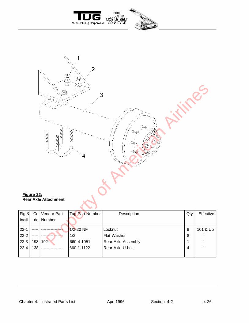
Fig & Co Vendor Part Tug Part Number Description Qty Effective
Ind# de Number
22-1 ----- ---------------- 1/2-20 NF Locknut 8 101 & Up
22-2 ----- ---------------- 1/2 Flat Washer 8 "
22-3 193 192 660-4-1051 Rear Axle Assembly 1 "
22-4 138 ---------------- 660-1-1122 Rear Axle U-bolt 4 "
Figure 22:Rear Axle Attachment
Prope
rty o
f Am
erica
n Airli
nes
Chapter 4: Illustrated Parts List Apr. 1996 Section 4-2 p. 27
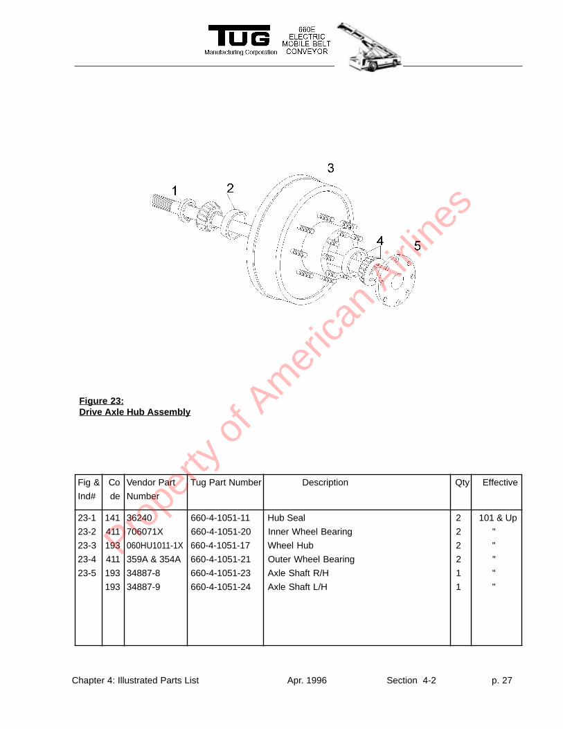
Fig & Co Vendor Part Tug Part Number Description Qty Effective
Ind# de Number
23-1 141 36240 660-4-1051-11 Hub Seal 2 101 & Up
23-2 411 706071X 660-4-1051-20 Inner Wheel Bearing 2 "
23-3 193 060HU1011-1X 660-4-1051-17 Wheel Hub 2 "
23-4 411 359A & 354A 660-4-1051-21 Outer Wheel Bearing 2 "
23-5 193 34887-8 660-4-1051-23 Axle Shaft R/H 1 "
193 34887-9 660-4-1051-24 Axle Shaft L/H 1 "
Figure 23:Drive Axle Hub Assembly
Prope
rty o
f Am
erica
n Airli
nes
Chapter 4: Illustrated Parts List Apr. 1996 Section 4-2 p. 28
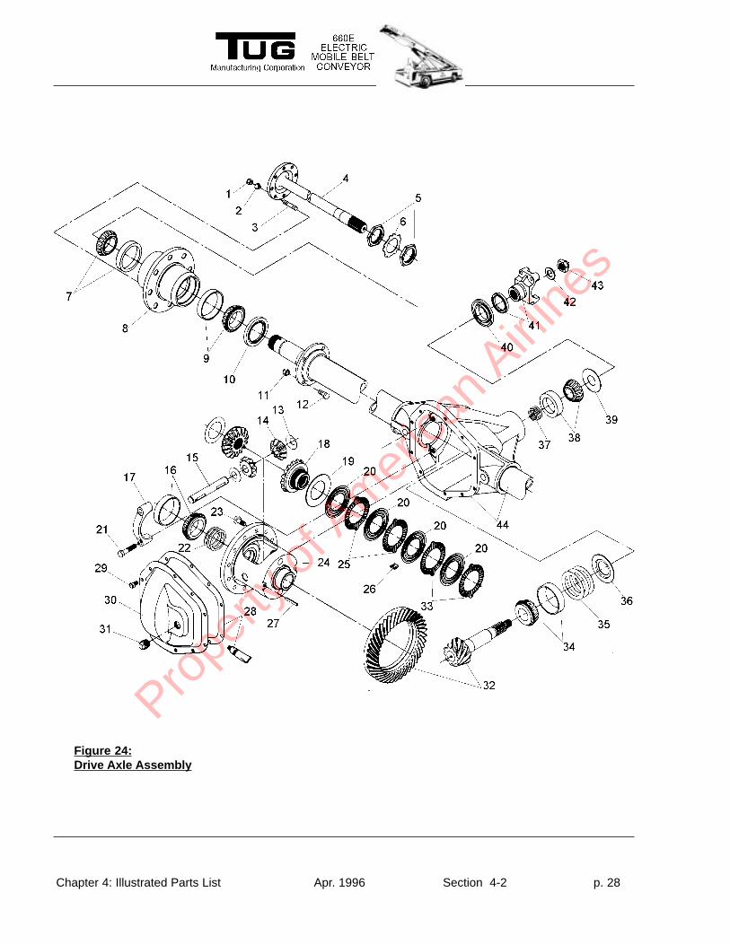
Figure 24:Drive Axle Assembly
Prope
rty o
f Am
erica
n Airli
nes
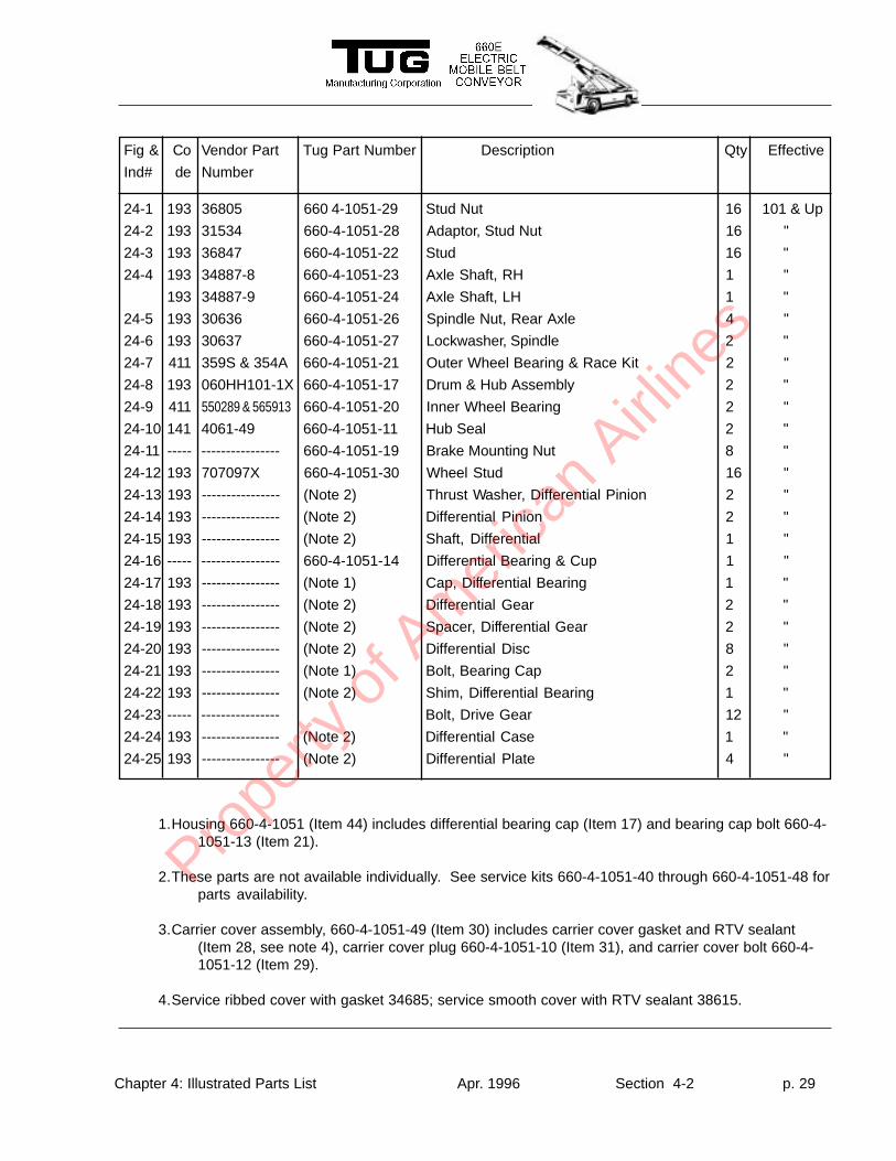
Chapter 4: Illustrated Parts List Apr. 1996 Section 4-2 p. 29
Fig & Co Vendor Part Tug Part Number Description Qty Effective
Ind# de Number
24-1 193 36805 660 4-1051-29 Stud Nut 16 101 & Up
24-2 193 31534 660-4-1051-28 Adaptor, Stud Nut 16 "
24-3 193 36847 660-4-1051-22 Stud 16 "
24-4 193 34887-8 660-4-1051-23 Axle Shaft, RH 1 "
193 34887-9 660-4-1051-24 Axle Shaft, LH 1 "
24-5 193 30636 660-4-1051-26 Spindle Nut, Rear Axle 4 "
24-6 193 30637 660-4-1051-27 Lockwasher, Spindle 2 "
24-7 411 359S & 354A 660-4-1051-21 Outer Wheel Bearing & Race Kit 2 "
24-8 193 060HH101-1X 660-4-1051-17 Drum & Hub Assembly 2 "
24-9 411 550289 & 565913 660-4-1051-20 Inner Wheel Bearing 2 "
24-10 141 4061-49 660-4-1051-11 Hub Seal 2 "
24-11 ----- ---------------- 660-4-1051-19 Brake Mounting Nut 8 "
24-12 193 707097X 660-4-1051-30 Wheel Stud 16 "
24-13 193 ---------------- (Note 2) Thrust Washer, Differential Pinion 2 "
24-14 193 ---------------- (Note 2) Differential Pinion 2 "
24-15 193 ---------------- (Note 2) Shaft, Differential 1 "
24-16 ----- ---------------- 660-4-1051-14 Differential Bearing & Cup 1 "
24-17 193 ---------------- (Note 1) Cap, Differential Bearing 1 "
24-18 193 ---------------- (Note 2) Differential Gear 2 "
24-19 193 ---------------- (Note 2) Spacer, Differential Gear 2 "
24-20 193 ---------------- (Note 2) Differential Disc 8 "
24-21 193 ---------------- (Note 1) Bolt, Bearing Cap 2 "
24-22 193 ---------------- (Note 2) Shim, Differential Bearing 1 "
24-23 ----- ---------------- Bolt, Drive Gear 12 "
24-24 193 ---------------- (Note 2) Differential Case 1 "
24-25 193 ---------------- (Note 2) Differential Plate 4 "
1.Housing 660-4-1051 (Item 44) includes differential bearing cap (Item 17) and bearing cap bolt 660-4-1051-13 (Item 21).
2.These parts are not available individually. See service kits 660-4-1051-40 through 660-4-1051-48 forparts availability.
3.Carrier cover assembly, 660-4-1051-49 (Item 30) includes carrier cover gasket and RTV sealant(Item 28, see note 4), carrier cover plug 660-4-1051-10 (Item 31), and carrier cover bolt 660-4-1051-12 (Item 29).
4.Service ribbed cover with gasket 34685; service smooth cover with RTV sealant 38615.
Prope
rty o
f Am
erica
n Airli
nes
Chapter 4: Illustrated Parts List Apr. 1996 Section 4-2 p. 30
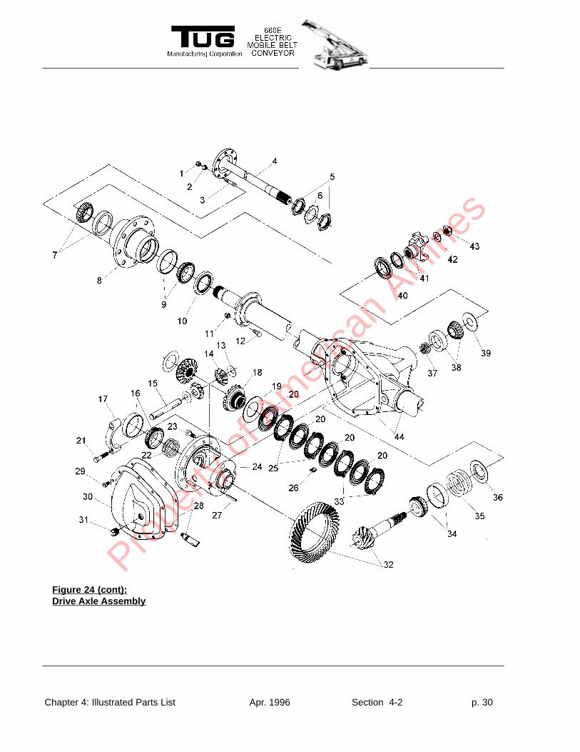
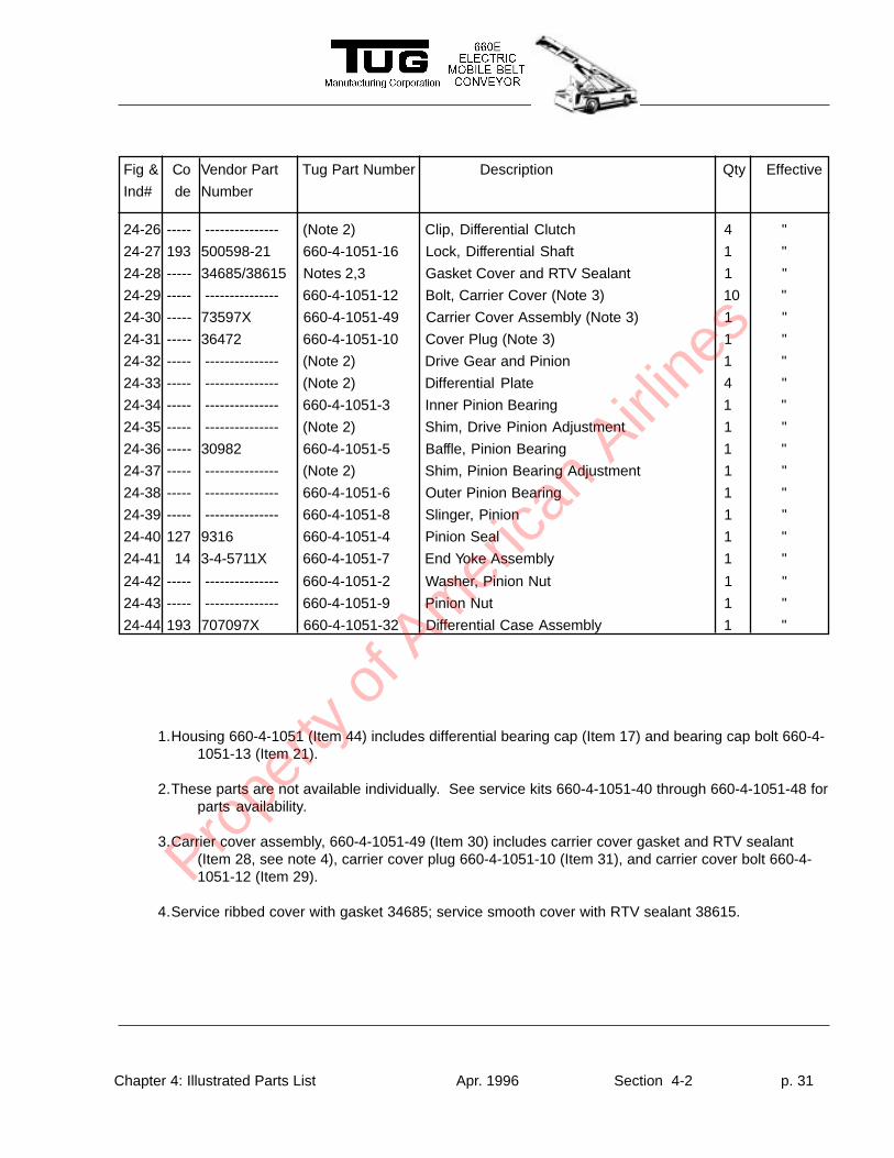
Figure 24 (cont):Drive Axle Assembly
Prope
rty o
f Am
erica
n Airli
nes
Chapter 4: Illustrated Parts List Apr. 1996 Section 4-2 p. 31
Fig & Co Vendor Part Tug Part Number Description Qty Effective
Ind# de Number
1.Housing 660-4-1051 (Item 44) includes differential bearing cap (Item 17) and bearing cap bolt 660-4-1051-13 (Item 21).
2.These parts are not available individually. See service kits 660-4-1051-40 through 660-4-1051-48 forparts availability.
3.Carrier cover assembly, 660-4-1051-49 (Item 30) includes carrier cover gasket and RTV sealant(Item 28, see note 4), carrier cover plug 660-4-1051-10 (Item 31), and carrier cover bolt 660-4-1051-12 (Item 29).
4.Service ribbed cover with gasket 34685; service smooth cover with RTV sealant 38615.
24-26 ----- --------------- (Note 2) Clip, Differential Clutch 4 "
24-27 193 500598-21 660-4-1051-16 Lock, Differential Shaft 1 "
24-28 ----- 34685/38615 Notes 2,3 Gasket Cover and RTV Sealant 1 "
24-29 ----- --------------- 660-4-1051-12 Bolt, Carrier Cover (Note 3) 10 "
24-30 ----- 73597X 660-4-1051-49 Carrier Cover Assembly (Note 3) 1 "
24-31 ----- 36472 660-4-1051-10 Cover Plug (Note 3) 1 "
24-32 ----- --------------- (Note 2) Drive Gear and Pinion 1 "
24-33 ----- --------------- (Note 2) Differential Plate 4 "
24-34 ----- --------------- 660-4-1051-3 Inner Pinion Bearing 1 "
24-35 ----- --------------- (Note 2) Shim, Drive Pinion Adjustment 1 "
24-36 ----- 30982 660-4-1051-5 Baffle, Pinion Bearing 1 "
24-37 ----- --------------- (Note 2) Shim, Pinion Bearing Adjustment 1 "
24-38 ----- --------------- 660-4-1051-6 Outer Pinion Bearing 1 "
24-39 ----- --------------- 660-4-1051-8 Slinger, Pinion 1 "
24-40 127 9316 660-4-1051-4 Pinion Seal 1 "
24-41 14 3-4-5711X 660-4-1051-7 End Yoke Assembly 1 "
24-42 ----- --------------- 660-4-1051-2 Washer, Pinion Nut 1 "
24-43 ----- --------------- 660-4-1051-9 Pinion Nut 1 "
24-44 193 707097X 660-4-1051-32 Differential Case Assembly 1 "
Prope
rty o
f Am
erica
n Airli
nes
Chapter 4: Illustrated Parts List Apr. 1996 Section 4-2 p. 32
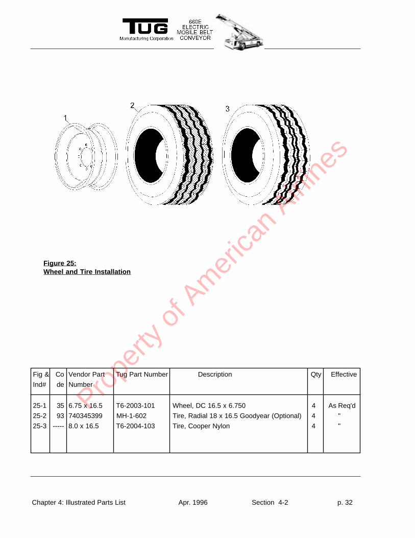
Figure 25:Wheel and T ire Installation
Fig & Co Vendor Part Tug Part Number Description Qty Effective
Ind# de Number
25-1 35 6.75 x 16.5 T6-2003-101 Wheel, DC 16.5 x 6.750 4 As Req'd
25-2 93 740345399 MH-1-602 Tire, Radial 18 x 16.5 Goodyear (Optional) 4 "
25-3 ----- 8.0 x 16.5 T6-2004-103 Tire, Cooper Nylon 4 "
Prope
rty o
f Am
erica
n Airli
nes
Chapter 4: Illustrated Parts List Apr. 1996 Section 4-2 p. 33
Fig & Co Vendor Part Tug Part Number Description Qty Effective
Ind# de Number
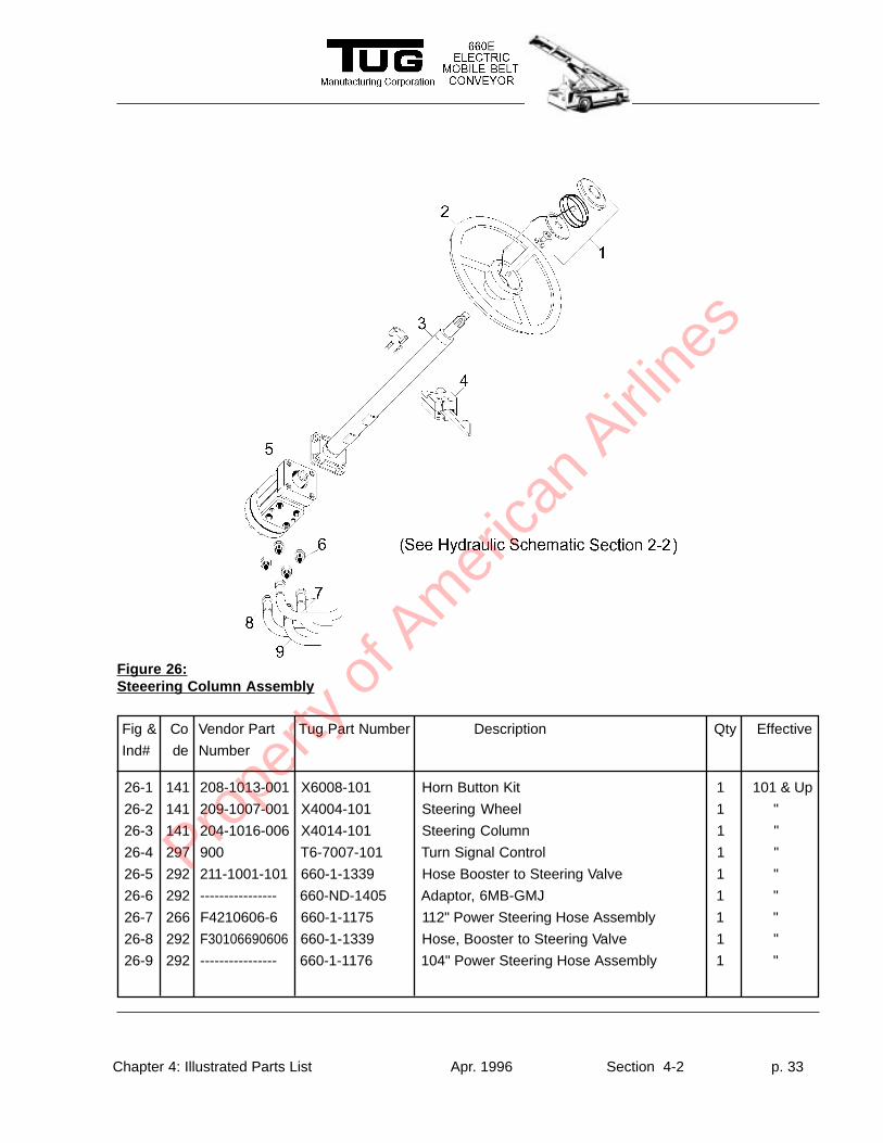
Figure 26:Steeering Column Assembly
26-1 141 208-1013-001 X6008-101 Horn Button Kit 1 101 & Up
26-2 141 209-1007-001 X4004-101 Steering Wheel 1 "
26-3 141 204-1016-006 X4014-101 Steering Column 1 "
26-4 297 900 T6-7007-101 Turn Signal Control 1 "
26-5 292 211-1001-101 660-1-1339 Hose Booster to Steering Valve 1 "
26-6 292 ---------------- 660-ND-1405 Adaptor, 6MB-GMJ 1 "
26-7 266 F4210606-6 660-1-1175 112" Power Steering Hose Assembly 1 "
26-8 292 F30106690606 660-1-1339 Hose, Booster to Steering Valve 1 "
26-9 292 ---------------- 660-1-1176 104" Power Steering Hose Assembly 1 "
Prope
rty o
f Am
erica
n Airli
nes
Chapter 4: Illustrated Parts List Apr. 1996 Section 4-2 p. 34
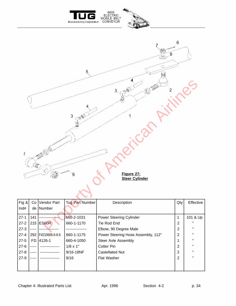
Fig & Co Vendor Part Tug Part Number Description Qty Effective
Ind# de Number
27-1 141 ---------------- 660-2-1031 Power Steering Cylinder 1 101 & Up
27-2 215 ES60R 660-1-1170 Tie Rod End 2 "
27-3 ----- --------------- ---------------- Elbow, 90 Degree Male 2 "
27-4 292 F4210606-6-6-6 660-1-1175 Power Steering Hose Assembly, 112" 2 "
27-5 FD 4126-1 660-4-1050 Steer Axle Assembly 1 "
27-6 ----- --------------- 1/8 x 1" Cotter Pin 2 "
27-8 ----- --------------- 9/16-18NF Castellated Nut 2 "
27-9 ----- --------------- 9/16 Flat Washer 2 "
Figure 27:Steer Cylinder
Prope
rty o
f Am
erica
n Airli
nes
Chapter 4: Illustrated Parts List Apr. 1996 Section 4-2 p. 35
Fig & Co Vendor Part Tug Part Number Description Qty Effective
Ind# de Number
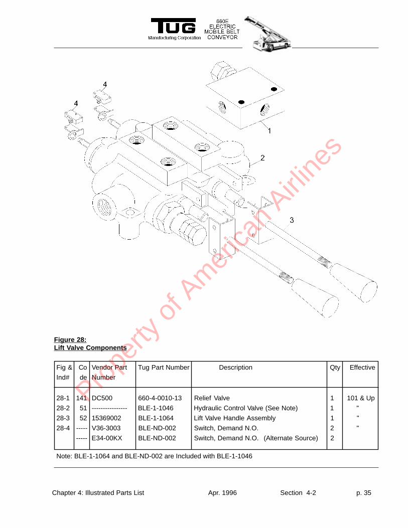
Figure 28:Lift V alve Components
28-1 141 DC500 660-4-0010-13 Relief Valve 1 101 & Up
28-2 51 ---------------- BLE-1-1046 Hydraulic Control Valve (See Note) 1 "
28-3 52 15369002 BLE-1-1064 Lift Valve Handle Assembly 1 "
28-4 ----- V36-3003 BLE-ND-002 Switch, Demand N.O. 2 "
----- E34-00KX BLE-ND-002 Switch, Demand N.O. (Alternate Source) 2
Note: BLE-1-1064 and BLE-ND-002 are Included with BLE-1-1046
Prope
rty o
f Am
erica
n Airli
nes
Chapter 4: Illustrated Parts List Apr. 1996 Section 4-2 p. 36
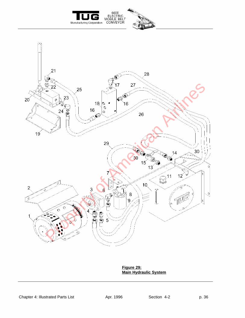
Figure 29:Main Hydraulic System
Prope
rty o
f Am
erica
n Airli
nes
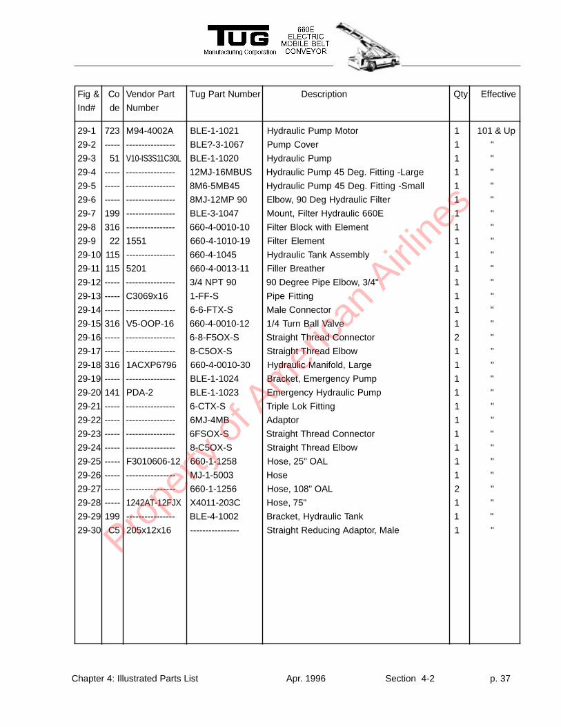
Chapter 4: Illustrated Parts List Apr. 1996 Section 4-2 p. 37
Fig & Co Vendor Part Tug Part Number Description Qty Effective
Ind# de Number
29-1 723 M94-4002A BLE-1-1021 Hydraulic Pump Motor 1 101 & Up
29-2 ----- ---------------- BLE?-3-1067 Pump Cover 1 "
29-3 51 V10-IS3S11C30L BLE-1-1020 Hydraulic Pump 1 "
29-4 ----- ---------------- 12MJ-16MBUS Hydraulic Pump 45 Deg. Fitting -Large 1 "
29-5 ----- ---------------- 8M6-5MB45 Hydraulic Pump 45 Deg. Fitting -Small 1 "
29-6 ----- ---------------- 8MJ-12MP 90 Elbow, 90 Deg Hydraulic Filter 1 "
29-7 199 ---------------- BLE-3-1047 Mount, Filter Hydraulic 660E 1 "
29-8 316 ---------------- 660-4-0010-10 Filter Block with Element 1 "
29-9 22 1551 660-4-1010-19 Filter Element 1 "
29-10 115 ---------------- 660-4-1045 Hydraulic Tank Assembly 1 "
29-11 115 5201 660-4-0013-11 Filler Breather 1 "
29-12 ----- ---------------- 3/4 NPT 90 90 Degree Pipe Elbow, 3/4" 1 "
29-13 ----- C3069x16 1-FF-S Pipe Fitting 1 "
29-14 ----- ---------------- 6-6-FTX-S Male Connector 1 "
29-15 316 V5-OOP-16 660-4-0010-12 1/4 Turn Ball Valve 1 "
29-16 ----- ---------------- 6-8-F5OX-S Straight Thread Connector 2 "
29-17 ----- ---------------- 8-C5OX-S Straight Thread Elbow 1 "
29-18 316 1ACXP6796 660-4-0010-30 Hydraulic Manifold, Large 1 "
29-19 ----- ---------------- BLE-1-1024 Bracket, Emergency Pump 1 "
29-20 141 PDA-2 BLE-1-1023 Emergency Hydraulic Pump 1 "
29-21 ----- ---------------- 6-CTX-S Triple Lok Fitting 1 "
29-22 ----- ---------------- 6MJ-4MB Adaptor 1 "
29-23 ----- ---------------- 6FSOX-S Straight Thread Connector 1 "
29-24 ----- ---------------- 8-C5OX-S Straight Thread Elbow 1 "
29-25 ----- F3010606-12 660-1-1258 Hose, 25" OAL 1 "
29-26 ----- ---------------- MJ-1-5003 Hose 1 "
29-27 ----- ---------------- 660-1-1256 Hose, 108" OAL 2 "
29-28 ----- 1242AT-12FJX X4011-203C Hose, 75" 1 "
29-29 199 ---------------- BLE-4-1002 Bracket, Hydraulic Tank 1 "
29-30 C5 205x12x16 ---------------- Straight Reducing Adaptor, Male 1 "Prope
rty o
f Am
erica
n Airli
nes
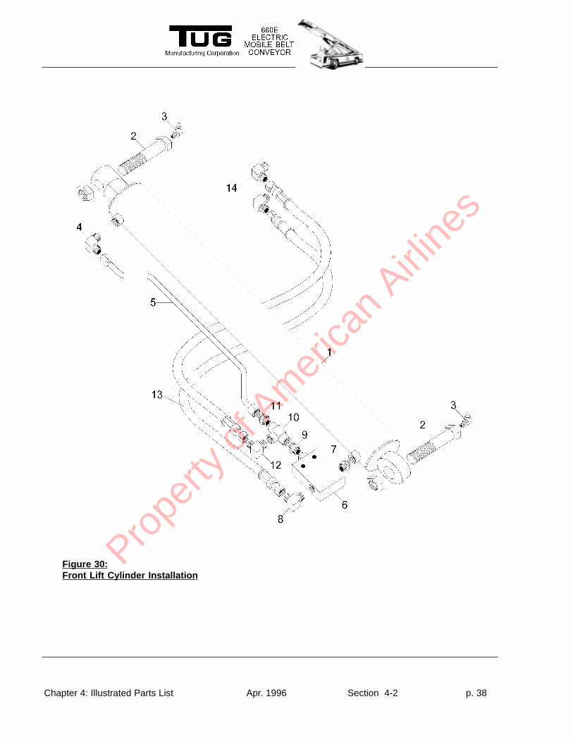
Chapter 4: Illustrated Parts List Apr. 1996 Section 4-2 p. 38
Figure 30:Front Lift Cylinder Installation
Prope
rty o
f Am
erica
n Airli
nes
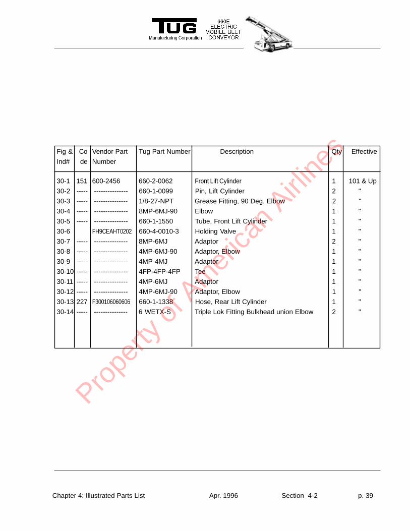
Chapter 4: Illustrated Parts List Apr. 1996 Section 4-2 p. 39
Fig & Co Vendor Part Tug Part Number Description Qty Effective
Ind# de Number
30-1 151 600-2456 660-2-0062 Front Lift Cylinder 1 101 & Up
30-2 ----- --------------- 660-1-0099 Pin, Lift Cylinder 2 "
30-3 ----- --------------- 1/8-27-NPT Grease Fitting, 90 Deg. Elbow 2 "
30-4 ----- --------------- 8MP-6MJ-90 Elbow 1 "
30-5 ----- --------------- 660-1-1550 Tube, Front Lift Cylinder 1 "
30-6 FH9CEAHT0202 660-4-0010-3 Holding Valve 1 "
30-7 ----- --------------- 8MP-6MJ Adaptor 2 "
30-8 ----- --------------- 4MP-6MJ-90 Adaptor, Elbow 1 "
30-9 ----- --------------- 4MP-4MJ Adaptor 1 "
30-10 ----- --------------- 4FP-4FP-4FP Tee 1 "
30-11 ----- --------------- 4MP-6MJ Adaptor 1 "
30-12 ----- --------------- 4MP-6MJ-90 Adaptor, Elbow 1 "
30-13 227 F300106060606 660-1-1338 Hose, Rear Lift Cylinder 1 "
30-14 ----- --------------- 6 WETX-S Triple Lok Fitting Bulkhead union Elbow 2 "
Prope
rty o
f Am
erica
n Airli
nes
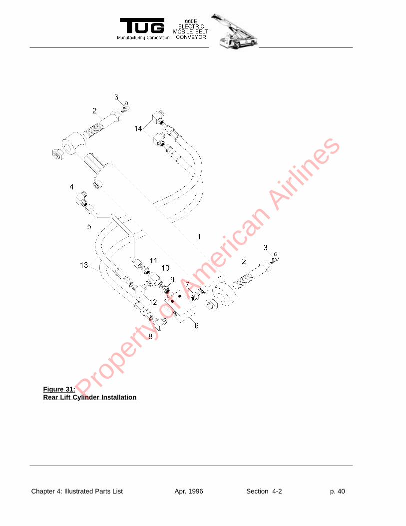
Chapter 4: Illustrated Parts List Apr. 1996 Section 4-2 p. 40
Figure 31:Rear Lift Cylinder InstallationPro
perty
of A
mer
ican
Airline
s
Chapter 4: Illustrated Parts List Apr. 1996 Section 4-2 p. 41
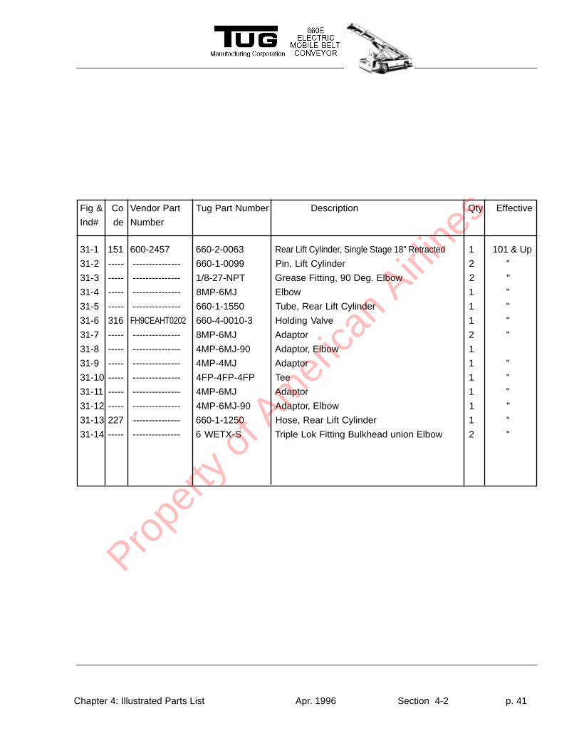
Fig & Co Vendor Part Tug Part Number Description Qty Effective
Ind# de Number
31-1 151 600-2457 660-2-0063 Rear Lift Cylinder, Single Stage 18" Retracted 1 101 & Up
31-2 ----- --------------- 660-1-0099 Pin, Lift Cylinder 2 "
31-3 ----- --------------- 1/8-27-NPT Grease Fitting, 90 Deg. Elbow 2 "
31-4 ----- --------------- 8MP-6MJ Elbow 1 "
31-5 ----- --------------- 660-1-1550 Tube, Rear Lift Cylinder 1 "
31-6 316 FH9CEAHT0202 660-4-0010-3 Holding Valve 1 "
31-7 ----- --------------- 8MP-6MJ Adaptor 2 "
31-8 ----- --------------- 4MP-6MJ-90 Adaptor, Elbow 1
31-9 ----- --------------- 4MP-4MJ Adaptor 1 "
31-10 ----- --------------- 4FP-4FP-4FP Tee 1 "
31-11 ----- --------------- 4MP-6MJ Adaptor 1 "
31-12 ----- --------------- 4MP-6MJ-90 Adaptor, Elbow 1 "
31-13 227 --------------- 660-1-1250 Hose, Rear Lift Cylinder 1 "
31-14 ----- --------------- 6 WETX-S Triple Lok Fitting Bulkhead union Elbow 2 "
Prope
rty o
f Am
erica
n Airli
nes
Chapter 4: Illustrated Parts List Apr. 1996 Section 4-2 p. 42
Fig & Co Vendor Part Tug Part Number Description Qty Effective
Ind# de Number
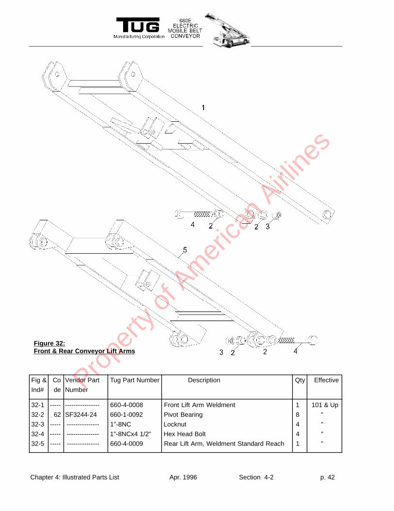
32-1 ----- ---------------- 660-4-0008 Front Lift Arm Weldment 1 101 & Up
32-2 62 SF3244-24 660-1-0092 Pivot Bearing 8 "
32-3 ----- --------------- 1"-8NC Locknut 4 "
32-4 ----- --------------- 1"-8NCx4 1/2" Hex Head Bolt 4 "
32-5 ----- --------------- 660-4-0009 Rear Lift Arm, Weldment Standard Reach 1 "
Figure 32:Front & Rear Conveyor Lift Arms
Prope
rty o
f Am
erica
n Airli
nes
Chapter 4: Illustrated Parts List Apr. 1996 Section 4-2 p. 43
Fig & Co Vendor Part Tug Part Number Description Qty Effective
Ind# de Number
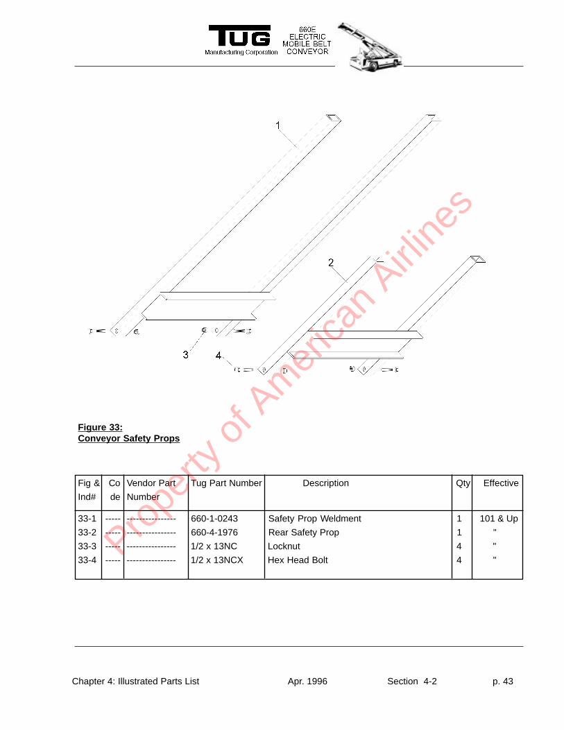
33-1 ----- ---------------- 660-1-0243 Safety Prop Weldment 1 101 & Up
33-2 ----- ---------------- 660-4-1976 Rear Safety Prop 1 "
33-3 ----- ---------------- 1/2 x 13NC Locknut 4 "
33-4 ----- ---------------- 1/2 x 13NCX Hex Head Bolt 4 "
Figure 33:Conveyor Safety Props
Prope
rty o
f Am
erica
n Airli
nes
Chapter 4: Illustrated Parts List Apr. 1996 Section 4-2 p. 44
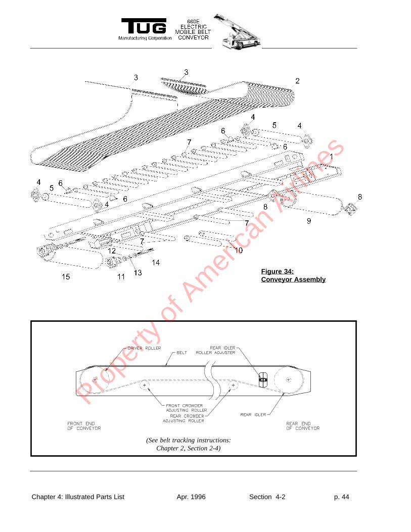
Figure 34:Conveyor Assembly
(See belt tracking instructions:Chapter 2, Section 2-4)
Prope
rty o
f Am
erica
n Airli
nes
Chapter 4: Illustrated Parts List Apr. 1996 Section 4-2 p. 45
Fig & Co Vendor Part Tug Part Number Description Qty Effective
Ind# de Number
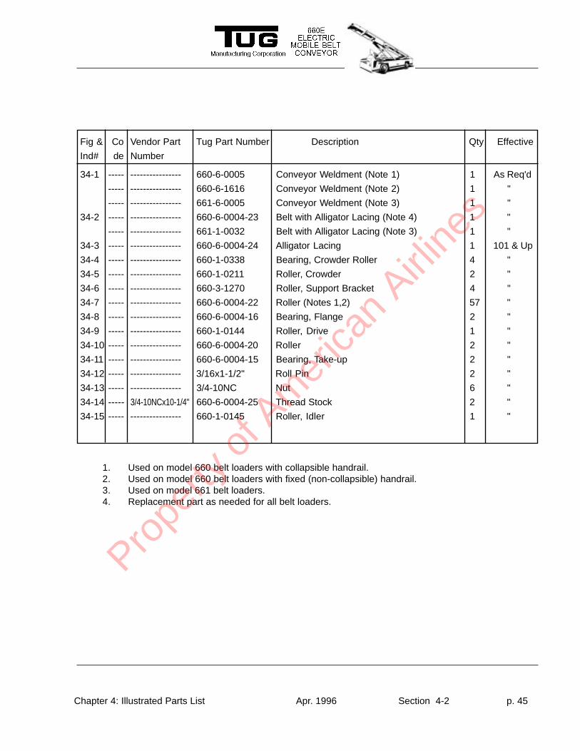
34-1 ----- ---------------- 660-6-0005 Conveyor Weldment (Note 1) 1 As Req'd
----- ---------------- 660-6-1616 Conveyor Weldment (Note 2) 1 "
----- ---------------- 661-6-0005 Conveyor Weldment (Note 3) 1 "
34-2 ----- ---------------- 660-6-0004-23 Belt with Alligator Lacing (Note 4) 1 "
----- ---------------- 661-1-0032 Belt with Alligator Lacing (Note 3) 1 "
34-3 ----- ---------------- 660-6-0004-24 Alligator Lacing 1 101 & Up
34-4 ----- ---------------- 660-1-0338 Bearing, Crowder Roller 4 "
34-5 ----- ---------------- 660-1-0211 Roller, Crowder 2 "
34-6 ----- ---------------- 660-3-1270 Roller, Support Bracket 4 "
34-7 ----- ---------------- 660-6-0004-22 Roller (Notes 1,2) 57 "
34-8 ----- ---------------- 660-6-0004-16 Bearing, Flange 2 "
34-9 ----- ---------------- 660-1-0144 Roller, Drive 1 "
34-10 ----- ---------------- 660-6-0004-20 Roller 2 "
34-11 ----- ---------------- 660-6-0004-15 Bearing, Take-up 2 "
34-12 ----- ---------------- 3/16x1-1/2" Roll Pin 2 "
34-13 ----- ---------------- 3/4-10NC Nut 6 "
34-14 ----- 3/4-10NCx10-1/4" 660-6-0004-25 Thread Stock 2 "
34-15 ----- ---------------- 660-1-0145 Roller, Idler 1 "
1. Used on model 660 belt loaders with collapsible handrail.2. Used on model 660 belt loaders with fixed (non-collapsible) handrail.3. Used on model 661 belt loaders.4. Replacement part as needed for all belt loaders.
Prope
rty o
f Am
erica
n Airli
nes
Chapter 4: Illustrated Parts List Apr. 1996 Section 4-2 p. 46
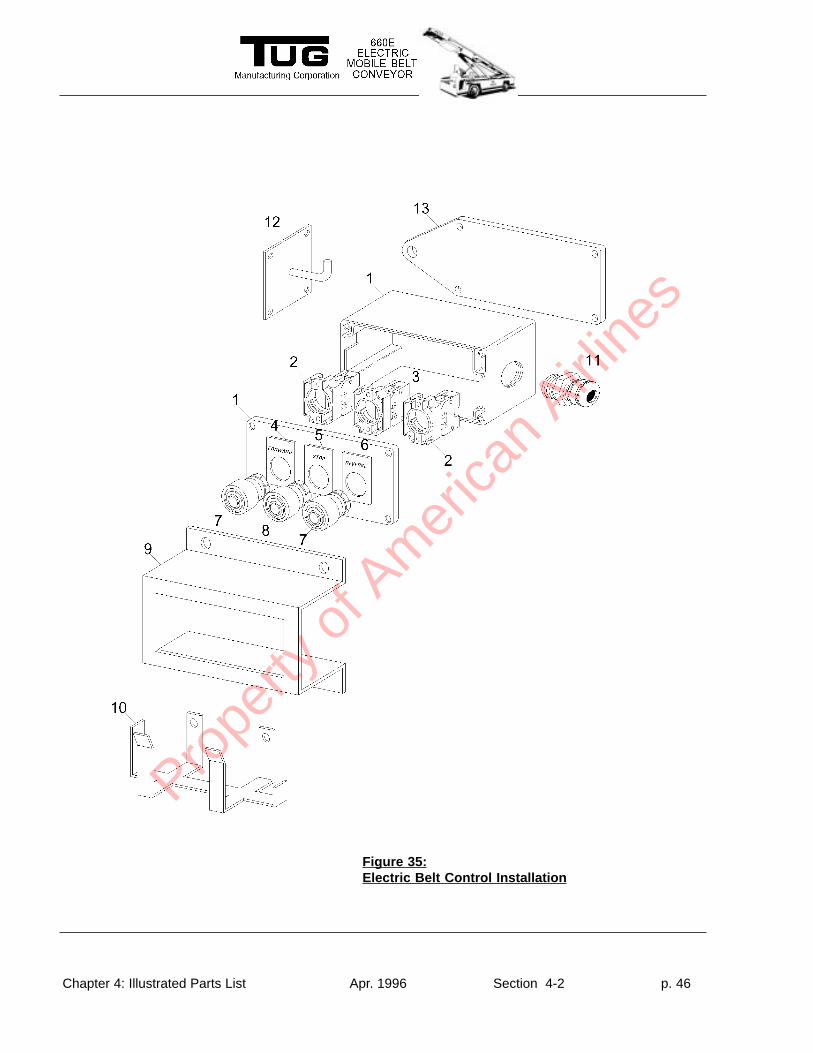
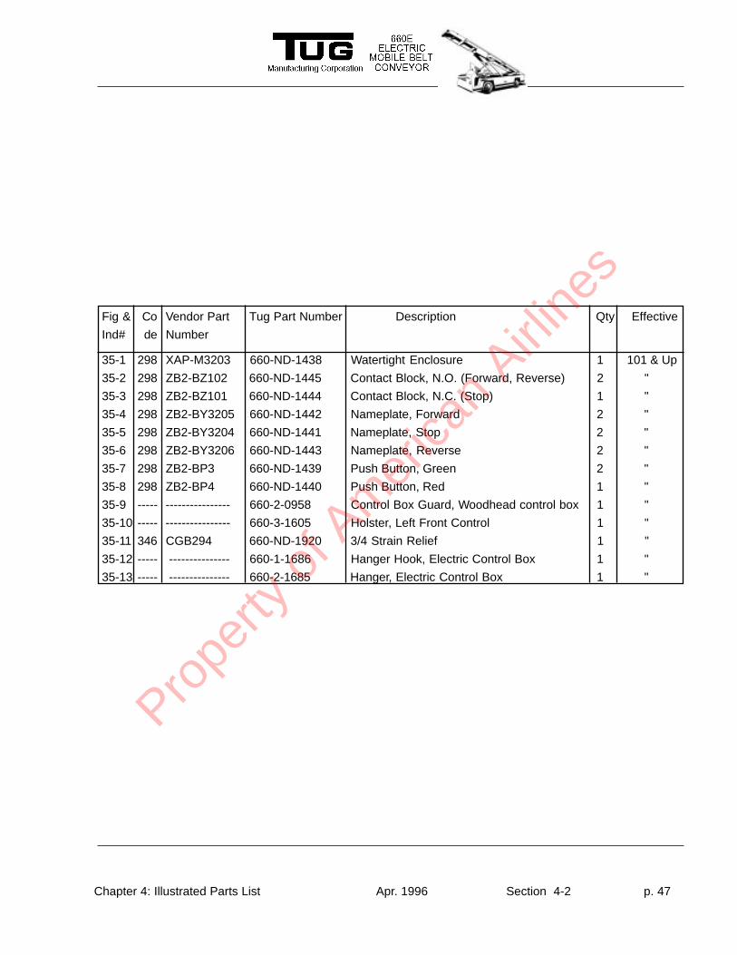
Figure 35:Electric Belt Control Installation
Prope
rty o
f Am
erica
n Airli
nes
Chapter 4: Illustrated Parts List Apr. 1996 Section 4-2 p. 47
Fig & Co Vendor Part Tug Part Number Description Qty Effective
Ind# de Number
35-1 298 XAP-M3203 660-ND-1438 Watertight Enclosure 1 101 & Up
35-2 298 ZB2-BZ102 660-ND-1445 Contact Block, N.O. (Forward, Reverse) 2 "
35-3 298 ZB2-BZ101 660-ND-1444 Contact Block, N.C. (Stop) 1 "
35-4 298 ZB2-BY3205 660-ND-1442 Nameplate, Forward 2 "
35-5 298 ZB2-BY3204 660-ND-1441 Nameplate, Stop 2 "
35-6 298 ZB2-BY3206 660-ND-1443 Nameplate, Reverse 2 "
35-7 298 ZB2-BP3 660-ND-1439 Push Button, Green 2 "
35-8 298 ZB2-BP4 660-ND-1440 Push Button, Red 1 "
35-9 ----- ---------------- 660-2-0958 Control Box Guard, Woodhead control box 1 "
35-10 ----- ---------------- 660-3-1605 Holster, Left Front Control 1 "
35-11 346 CGB294 660-ND-1920 3/4 Strain Relief 1 "
35-12 ----- --------------- 660-1-1686 Hanger Hook, Electric Control Box 1 "
35-13 ----- --------------- 660-2-1685 Hanger, Electric Control Box 1 "
Prope
rty o
f Am
erica
n Airli
nes
Chapter 4: Illustrated Parts List Apr. 1996 Section 4-2 p. 48
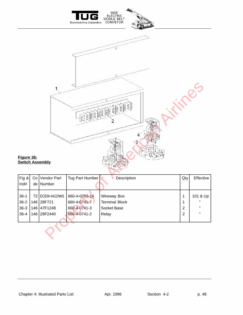
Figure 36:Switch Assembly
Fig & Co Vendor Part Tug Part Number Description Qty Effective
Ind# de Number
36-1 72 ECEW-4412NM1 660-4-0753-14 Wireway Box 1 101 & Up
36-2 146 28F721 660-4-0741-7 Terminal Block 1 "
36-3 146 47F1248 660-4-0741-3 Socket Base 2 "
36-4 146 29F2440 660-4-0741-2 Relay 2 "
Prope
rty o
f Am
erica
n Airli
nes
Chapter 4: Illustrated Parts List Apr. 1996 Section 4-2 p. 49
Fig & Co Vendor Part Tug Part Number Description Qty Effective
Ind# de Number
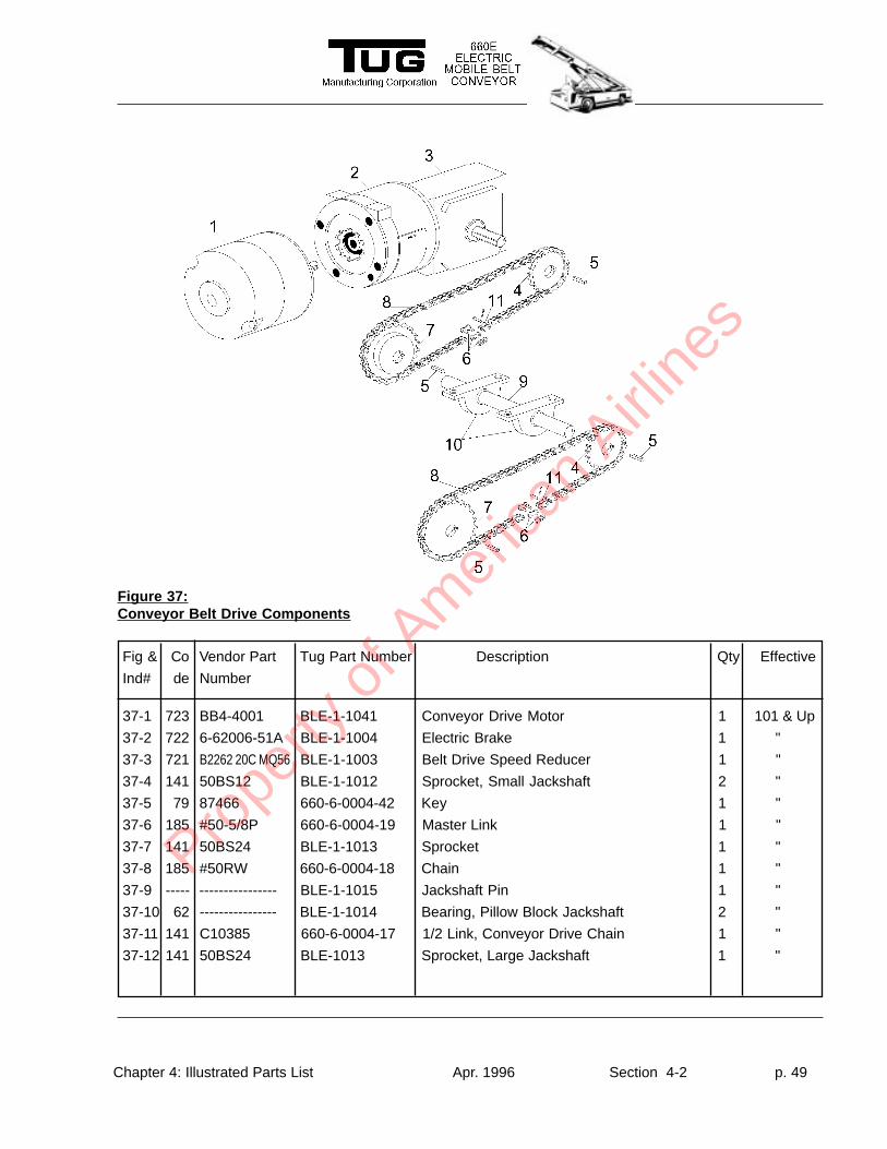
Figure 37:Conveyor Belt Drive Components
37-1 723 BB4-4001 BLE-1-1041 Conveyor Drive Motor 1 101 & Up
37-2 722 6-62006-51A BLE-1-1004 Electric Brake 1 "
37-3 721 B2262 20C MQ56 BLE-1-1003 Belt Drive Speed Reducer 1 "
37-4 141 50BS12 BLE-1-1012 Sprocket, Small Jackshaft 2 "
37-5 79 87466 660-6-0004-42 Key 1 "
37-6 185 #50-5/8P 660-6-0004-19 Master Link 1 "
37-7 141 50BS24 BLE-1-1013 Sprocket 1 "
37-8 185 #50RW 660-6-0004-18 Chain 1 "
37-9 ----- ---------------- BLE-1-1015 Jackshaft Pin 1 "
37-10 62 ---------------- BLE-1-1014 Bearing, Pillow Block Jackshaft 2 "
37-11 141 C10385 660-6-0004-17 1/2 Link, Conveyor Drive Chain 1 "
37-12 141 50BS24 BLE-1013 Sprocket, Large Jackshaft 1 "
Prope
rty o
f Am
erica
n Airli
nes
Chapter 4: Illustrated Parts List Apr. 1996 Section 4-2 p. 50
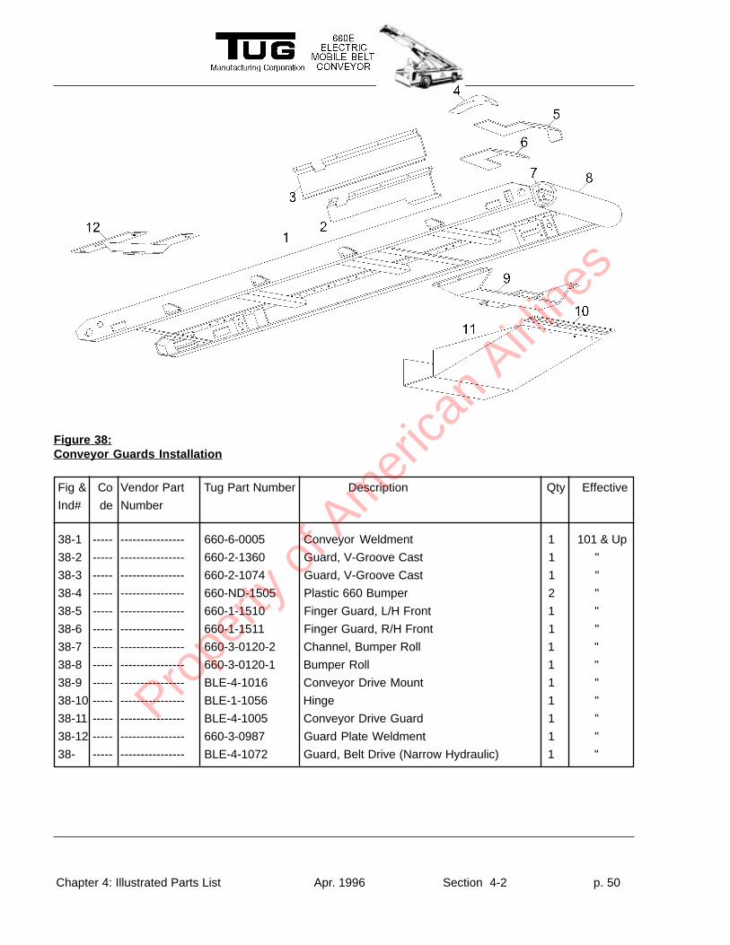
Fig & Co Vendor Part Tug Part Number Description Qty Effective
Ind# de Number
38-1 ----- ---------------- 660-6-0005 Conveyor Weldment 1 101 & Up
38-2 ----- ---------------- 660-2-1360 Guard, V-Groove Cast 1 "
38-3 ----- ---------------- 660-2-1074 Guard, V-Groove Cast 1 "
38-4 ----- ---------------- 660-ND-1505 Plastic 660 Bumper 2 "
38-5 ----- ---------------- 660-1-1510 Finger Guard, L/H Front 1 "
38-6 ----- ---------------- 660-1-1511 Finger Guard, R/H Front 1 "
38-7 ----- ---------------- 660-3-0120-2 Channel, Bumper Roll 1 "
38-8 ----- ---------------- 660-3-0120-1 Bumper Roll 1 "
38-9 ----- ---------------- BLE-4-1016 Conveyor Drive Mount 1 "
38-10 ----- ---------------- BLE-1-1056 Hinge 1 "
38-11 ----- ---------------- BLE-4-1005 Conveyor Drive Guard 1 "
38-12 ----- ---------------- 660-3-0987 Guard Plate Weldment 1 "
38- ----- ---------------- BLE-4-1072 Guard, Belt Drive (Narrow Hydraulic) 1 "
Figure 38:Conveyor Guards Installation
Prope
rty o
f Am
erica
n Airli
nes
Chapter 4: Illustrated Parts List Apr. 1996 Section 4-2 p. 51
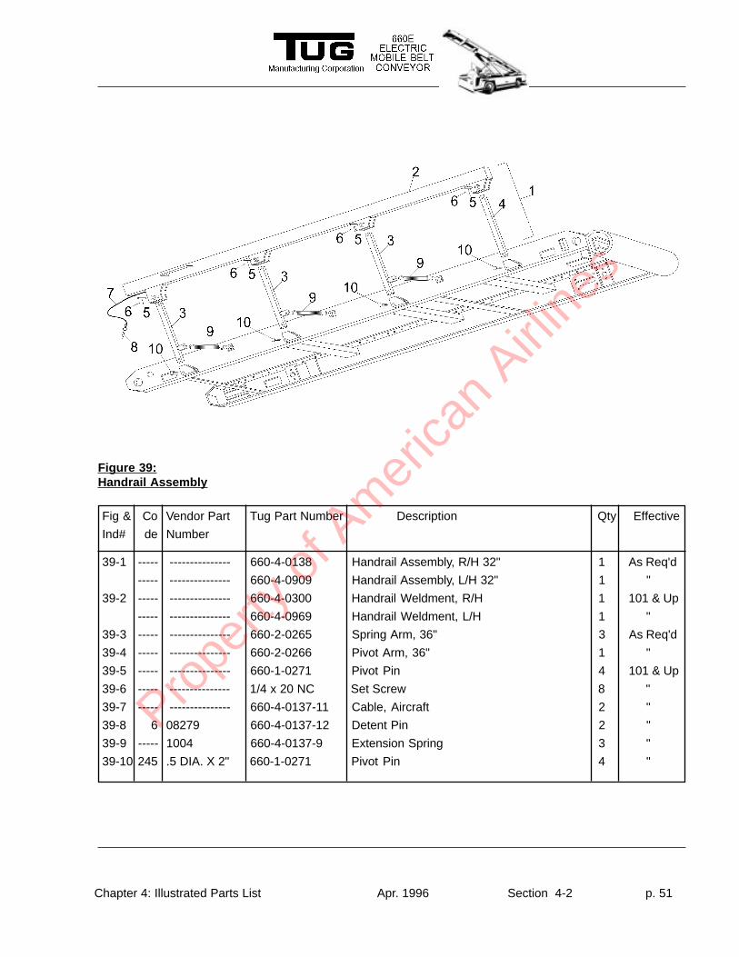
Fig & Co Vendor Part Tug Part Number Description Qty Effective
Ind# de Number
39-1 ----- --------------- 660-4-0138 Handrail Assembly, R/H 32" 1 As Req'd
----- --------------- 660-4-0909 Handrail Assembly, L/H 32" 1 "
39-2 ----- --------------- 660-4-0300 Handrail Weldment, R/H 1 101 & Up
----- --------------- 660-4-0969 Handrail Weldment, L/H 1 "
39-3 ----- --------------- 660-2-0265 Spring Arm, 36" 3 As Req'd
39-4 ----- --------------- 660-2-0266 Pivot Arm, 36" 1 "
39-5 ----- --------------- 660-1-0271 Pivot Pin 4 101 & Up
39-6 ----- --------------- 1/4 x 20 NC Set Screw 8 "
39-7 ----- --------------- 660-4-0137-11 Cable, Aircraft 2 "
39-8 6 08279 660-4-0137-12 Detent Pin 2 "
39-9 ----- 1004 660-4-0137-9 Extension Spring 3 "
39-10 245 .5 DIA. X 2" 660-1-0271 Pivot Pin 4 "
Figure 39:Handrail Assembly
Prope
rty o
f Am
erica
n Airli
nes
Chapter 4: Illustrated Parts List Apr. 1996 Section 4-2 p. 52
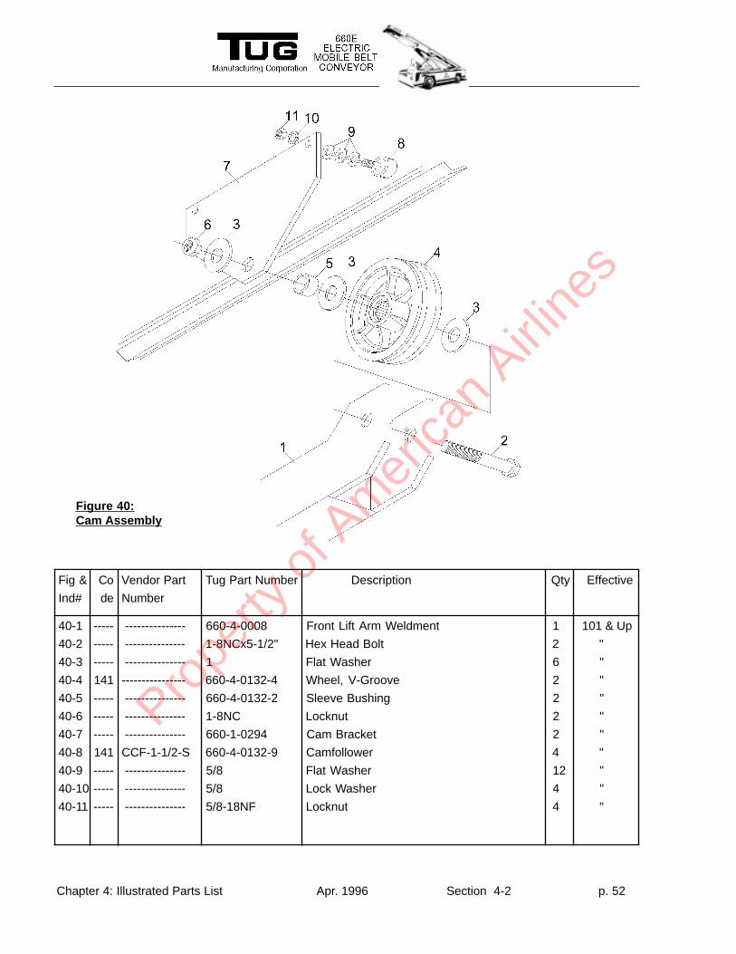
Fig & Co Vendor Part Tug Part Number Description Qty Effective
Ind# de Number
40-1 ----- --------------- 660-4-0008 Front Lift Arm Weldment 1 101 & Up
40-2 ----- --------------- 1-8NCx5-1/2" Hex Head Bolt 2 "
40-3 ----- --------------- 1 Flat Washer 6 "
40-4 141 ---------------- 660-4-0132-4 Wheel, V-Groove 2 "
40-5 ----- --------------- 660-4-0132-2 Sleeve Bushing 2 "
40-6 ----- --------------- 1-8NC Locknut 2 "
40-7 ----- --------------- 660-1-0294 Cam Bracket 2 "
40-8 141 CCF-1-1/2-S 660-4-0132-9 Camfollower 4 "
40-9 ----- --------------- 5/8 Flat Washer 12 "
40-10 ----- --------------- 5/8 Lock Washer 4 "
40-11 ----- --------------- 5/8-18NF Locknut 4 "
Figure 40:Cam Assembly
Prope
rty o
f Am
erica
n Airli
nes
Chapter 4: Illustrated Parts List Apr. 1996 Section 4-2 p. 53
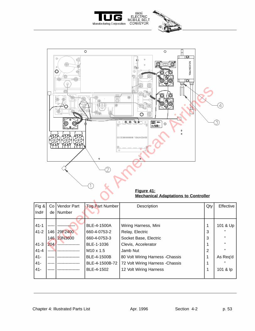
Figure 41:Mechanical Adaptations to Controller
Fig & Co Vendor Part Tug Part Number Description Qty Effective
Ind# de Number
41-1 ----- ---------------- BLE-4-1500A Wiring Harness, Mini 1 101 & Up
41-2 146 29F2400 660-4-0753-2 Relay, Electric 3 "
146 23N3600 660-4-0753-3 Socket Base, Electric 3 "
41-3 204 ---------------- BLE-1-1036 Clevis, Accelerator 1 "
41-4 ----- ---------------- M10 x 1.5 Jamb Nut 2 "
41- ----- ---------------- BLE-4-1500B 80 Volt Wiring Harness -Chassis 1 As Req'd
41- ----- ---------------- BLE-4-1500B-72 72 Volt Wiring Harness -Chassis 1 "
41- ----- ---------------- BLE-4-1502 12 Volt Wiring Harness 1 101 & Ip
Prope
rty o
f Am
erica
n Airli
nes
Chapter 4: Illustrated Parts List Apr. 1996 Section 4-2 p. 54
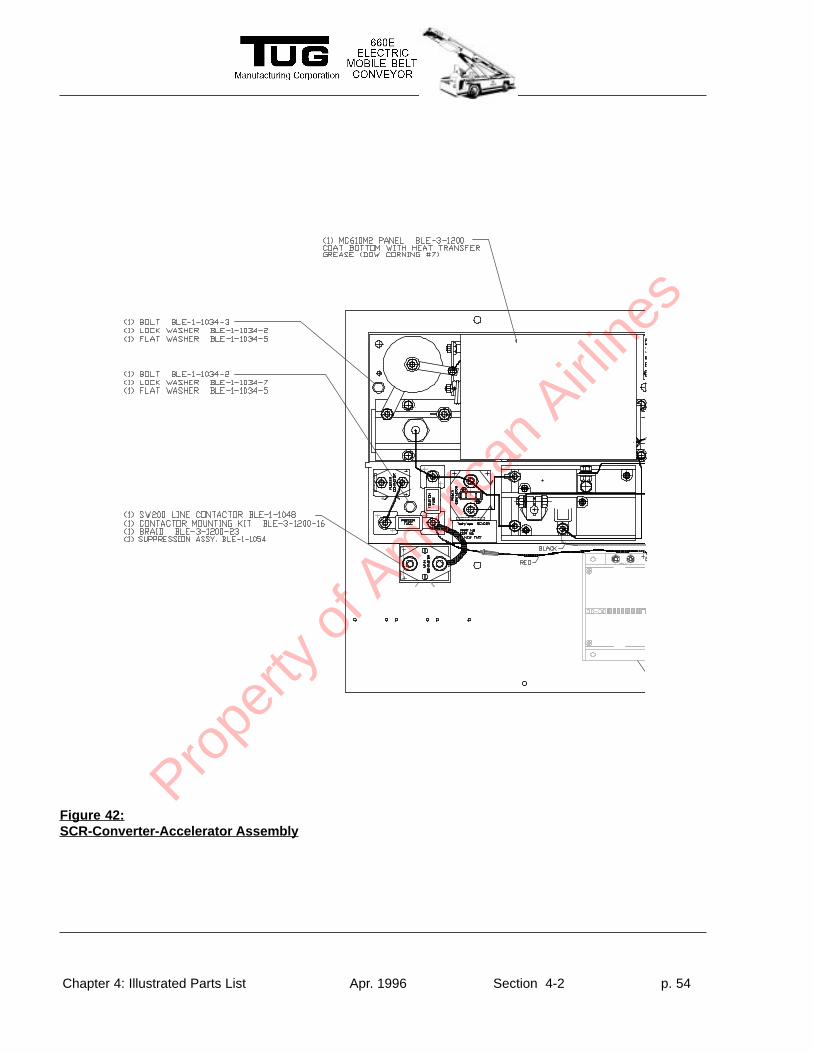
Figure 42:SCR-Converter-Accelerator Assembly
Prope
rty o
f Am
erica
n Airli
nes
Chapter 4: Illustrated Parts List Apr. 1996 Section 4-2 p. 55
Prope
rty o
f Am
erica
n Airli
nes
Chapter 4: Illustrated Parts List Apr. 1996 Section 4-2 p. 56
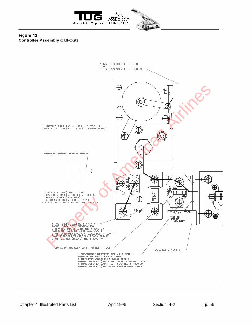
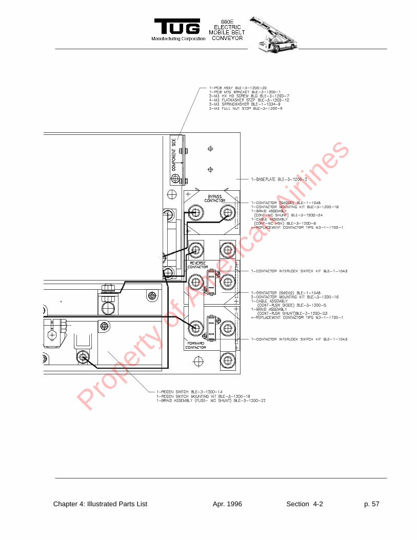
Figure 43:Controller Assembly Call-Outs
Prope
rty o
f Am
erica
n Airli
nes
Chapter 4: Illustrated Parts List Apr. 1996 Section 4-2 p. 57
Prope
rty o
f Am
erica
n Airli
nes
Chapter 4: Illustrated Parts List Apr. 1996 Section 4-2 p. 58
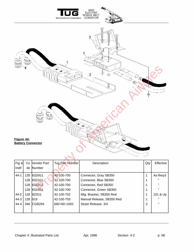
Figure 44:Battery Connector
Fig & Co Vendor Part Tug Part Number Description Qty Effective
Ind# de Number
44-1 128 6320G1 42-100-700 Connector, Gray SB350 1 As Req'd
128 6321G1 42-100-700 Connector, Blue SB350 1 "
128 6322G1 42-100-700 Connector, Red SB350 1 "
128 6324G1 42-100-700 Connector, Green SB350 1 "
44-2 128 922G1 42-100-702 Mtg. Bracket, SB350 Red 1 101 & Up
44-3 128 919 42-100-703 Manual Release, SB350 Red 1 "
44-4 346 CGB294 660-ND-1920 Strain Release, 3/4 2 "
Prope
rty o
f Am
erica
n Airli
nes
Chapter 4: Illustrated Parts List Apr. 1996 Section 4-2 p. 59
Fig & Co Vendor Part Tug Part Number Description Qty Effective
Ind# de Number
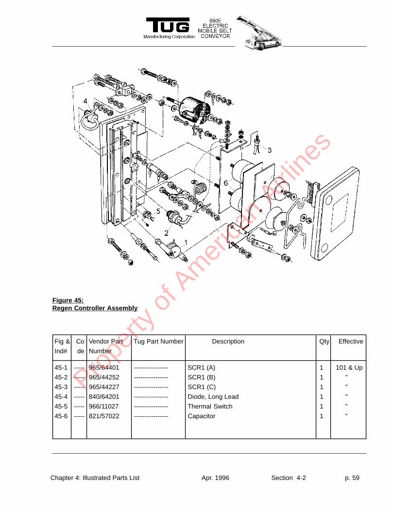
45-1 ----- 965/64401 ---------------- SCR1 (A) 1 101 & Up
45-2 ----- 965/44252 ---------------- SCR1 (B) 1 "
45-3 ----- 965/44227 ---------------- SCR1 (C) 1 "
45-4 ----- 840/64201 ---------------- Diode, Long Lead 1 "
45-5 ----- 966/11027 ---------------- Thermal Switch 1 "
45-6 ----- 821/57022 ---------------- Capacitor 1 "
Figure 45:Regen Controller Assembly
Prope
rty o
f Am
erica
n Airli
nes
Chapter 4: Illustrated Parts List Apr. 1996 Section 4-2 p. 60
This Page Intentionally Left Blank
Prope
rty o
f Am
erica
n Airli
nes
Chapter 4: Illustrated Parts List Aug. 1995 Section 4-3 p. 1
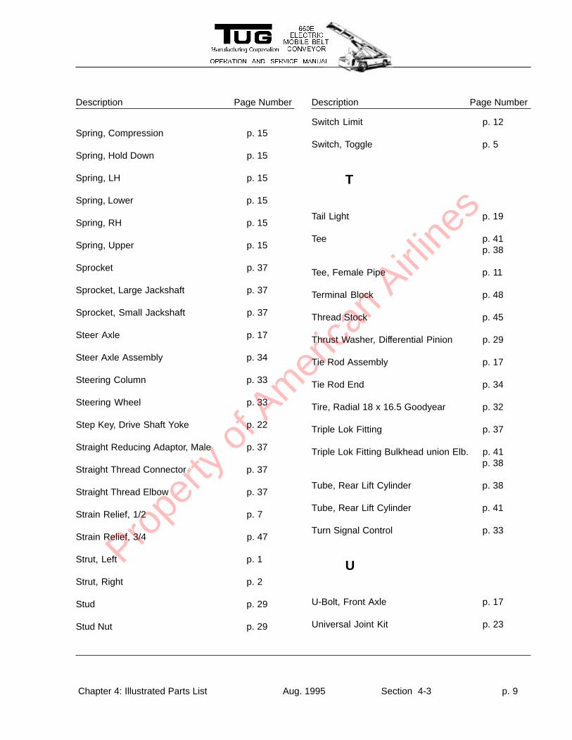
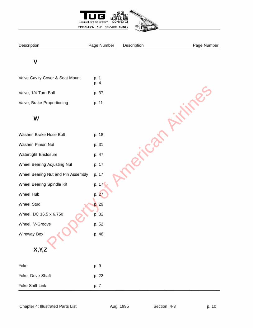
Description Page Number Description Page NumberThe alphabetical index is provided for your convenience as a handy way of locating, by description,
specific parts in the illustrated parts list. The index lists both the description of the part and the section 4-2page number.
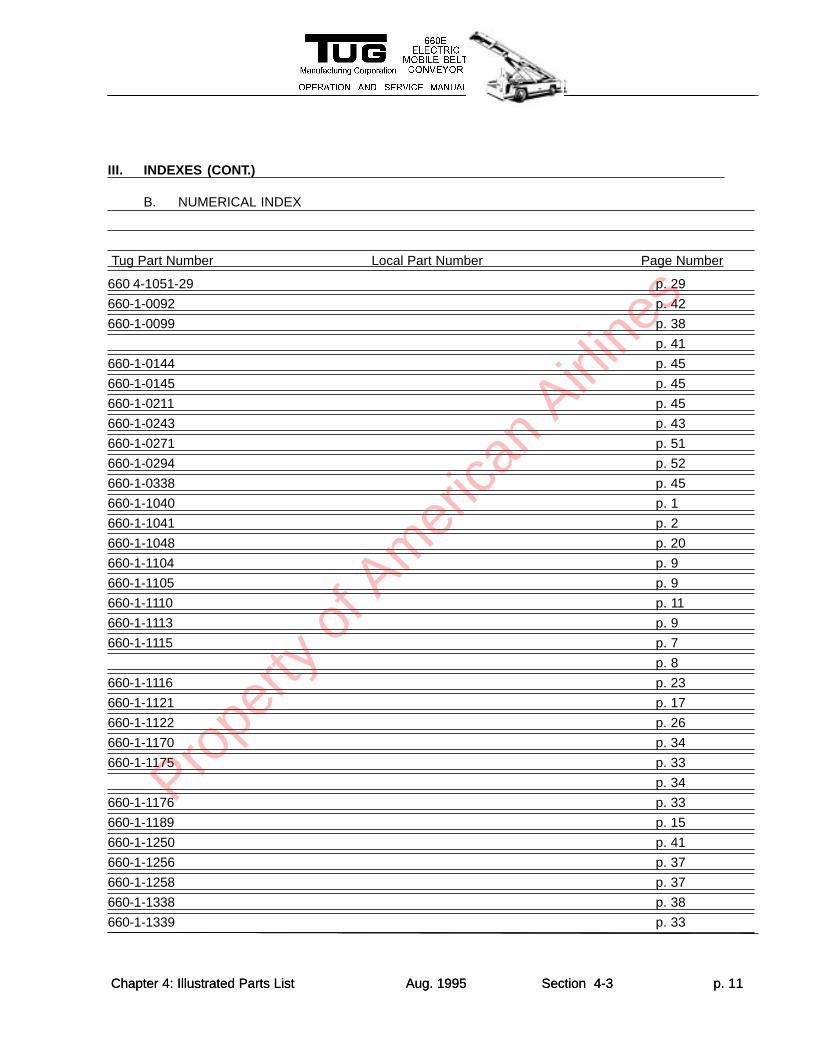
The numerical index is provided to enable the user to develop his own cross-reference to local partnumbers. As the user attaches local part numbers to the parts in this section, those part numbers may beentered into this chart for future reference.
A. ALPHABETICAL INDEX
Chapter 4: Illustrated Parts List Aug. 1995 Section 4-1 p. 1
III. INDEXES
Description Page Number Description Page Number
A
Accelerator Cable p. 7
Accelerator Cable, Gas p. 8
Adaptor p. 38p. 41p. 37
Adaptor, 6MB-GMJ p. 33
Adaptor, Brake p. 9
Adaptor, Elbow p. 38p. 41
Adaptor, Stud Nut p. 29
Adjusting Screw, LH p. 15
Adjusting Screw, RH p. 15
Alligator Lacing p. 45
Anchor Bolt p. 15
Anchor, Park Brake p. 13
Anchor, Park Brake Cable p. 13
Angle, Hand Brake p. 12
Axle Shaft L/H p. 29
Axle Shaft R/H p. 27
Axle Shaft, LH p. 29
Axle Shaft, RH p. 29
Axle Stop p. 17
B
Back up Light p. 19
Baffle, Pinion Bearing p. 31
Base Plate Shifter Switch p. 7
Battery Door p. 1
Battery, Electric Belt Loader, 72V p. 22
Battery, Electric Belt Loader, 80V p. 22
BDI/Hourmeter/Lockout p. 5
Bearing, Crowder Roller p. 45
Bearing, Flange p. 45
Bearing, Input p. 25
Prope
rty o
f Am
erica
n Airli
nes
Chapter 4: Illustrated Parts List Aug. 1995 Section 4-3 p. 2
Description Page Number Description Page Number
Bearing, Input Cover p. 25
Bearing, Outboard Input Shaft p. 25
Bearing, Outboard Ouput Shaft p. 25
Bearing, Pillow Block Jackshaft p. 37
Bearing, Take-up p. 45
Bell Crank p. 9
Belt Drive Speed Reducer p. 37
Belt with Alligator Lacing p. 45
Belt with Alligator Lacing p. 45
Blank Plug p. 5
Blank Plug, Dash p. 5
Bleed Valve p. 18
Bolt and Lock Washer Assembly p. 15
Bolt, Bearing Cap p. 29
Bolt, Brake Hose p. 18
Bolt, Carrier Cover p. 31
Bolt, Drive Gear p. 29
Bolt, Housing Retainer w/o cotter pin p. 18
Bracket, Emergency Pump p. 37
Bracket, Hydraulic Tank p. 37
Brake Hose p. 11p. 18
Brake Line 20" p. 11
Brake Line 30" p. 11
Brake Line 40" p. 11
Brake Line 50" p. 11
Brake Line 6" p. 11
Brake Line Connector p. 11
Brake Mounting Nut p. 29
Brake Pads Kit, Organic p. 18
Brake Pedal Assembly p. 9
Brake Switch p. 11
Brake, Cable Long p. 13
Brake, Cable Short p. 13
Breaker, 20 Amp Circuit p. 20
Breather p. 25
Bumper Roll p. 50
Bushing p. 9
C
Cable Assembly p. 15
Cable Clamp p. 8
Cable Clevis p. 8
Cable Guide p. 15
Cable, Aircraft p. 51
Cable, Shifter p. 6
Caliper, Single Piston p. 18
Cam Bracket p. 52
Prope
rty o
f Am
erica
n Airli
nes
Chapter 4: Illustrated Parts List Aug. 1995 Section 4-3 p. 3
Description Page Number Description Page Number
Cam Plate, LH p. 15
Cam Plate, RH p. 15
Camfollower p. 52
Cap Plug p. 17
Cap, Differential Bearing p. 29
Carrier Cover Assembly p. 31
Castellated Nut p. 34
Chain p. 37
Chain Coupling p. 22
Channel, Bumper Roll p. 50
Circuit Breaker Plate p. 20
Clamp, Cable p. 7
Clip, Brake Line p. 13
Clip, Differential Clutch p. 31
Closeout, Headlight p. 1
Connecting Link, Cylinder p. 15
Contact Block, N.C. (Stop) p. 47
Contact Block, N.O. (Fwd, Rev) p. 47
Control Box Guard, Woodhead p. 47
Conveyor Drive Guard p. 50
Conveyor Drive Motor p. 37
Conveyor Drive Mount p. 50
Conveyor Weldment p. 45p. 50
Cotter Pin p. 34p. 9
Countersunk Bolt p. 20
Coupling, Sprocket -Motor Side p. 22
Coupling, Sprocket -Reducer Side p. 22
Cover p. 15
Cover, Chain Coupling p. 22
Cover Plug p. 31
Cover, Motor 660E p. 23
Cylinder Assembly, LH p. 15
Cylinder Assembly, RH p. 15
D
Detent Pin p. 51
Differential Bearing & Cup p. 29
Differential Case p. 29
Differential Case Assembly p. 31
Differential Disc p. 29
Differential Gear p. 29
Differential Pinion p. 29
Differential Plate p. 29p. 31
Door, Battery p. 22
Door, Hydraulic Electric Belt Loader p. 2
Drive Gear and Pinion p. 31
Prope
rty o
f Am
erica
n Airli
nes
Chapter 4: Illustrated Parts List Aug. 1995 Section 4-3 p. 4
Description Page Number Description Page Number
Drive Motor p. 23
Drive Motor Mount p. 23
Drive Motor Reducer p. 23
Drive Shaft p. 23
Drum & Hub Assembly p. 29
Drum Brake Shoe Kit p. 15
E
Elbow p. 41p. 38
Elbow, 90 Deg Hydraulic Filter p. 37
Elbow, 90 Degree Male p. 34
Elbow, 90 Degree Pipe 3/4" p. 37
Electric Brace p. 37
Electronics Enclosure, EBL p. 7
Emergency Brake Cable p. 12p. 13
Emergency Hydraulic Pump p. 37
End Yoke Assembly p. 31
End Yoke, Adjustable p. 12
Equalizer p. 13
Extension Spring p. 51
F
Fender Well Liner p. 1
Fender, Center Left p. 22
Fender Tie Bar p. 1
Fiber Locknut p. 20
Filler Breather p. 37
Filter Block with Element p. 37
Filter Element p. 37
Finger Guard, L/H Front p. 50
Finger Guard, R/H Front p. 50
Flat Washer p. 15p. 17p. 20p. 21p. 26p. 34p. 52
Frame Weldment p. 3
Front Lift Arm Weldment p. 42p. 52
Front Lift Cylinder p. 38
G
Gasket Cover and RTV Sealant p. 31
Gear Housing p. 25
Gear Oil Levelling Plug p. 25
Gear, High Speed p. 25
Grease Fitting, 90 Deg. Elbow p. 41p. 38
Guard Plate Weldment p. 50
Prope
rty o
f Am
erica
n Airli
nes
Chapter 4: Illustrated Parts List Aug. 1995 Section 4-3 p. 5
Description Page Number Description Page Number
Guard, V-Groove Cast p. 50
H
Handrail Assembly, L/H 32" p. 51
Handrail Assembly, R/H 32" p. 51
Handrail Weldment, R/H p. 51
Hanger Hook, Electric Control Box p. 47
Hanger, Electric Control Box p. 47
Headlight p. 19
Hex Head Bolt p. 21p. 42p. 43p. 52
Hex head Bolt and Nut p. 9
Hinge p. 2p. 50
Hinge, Piano p. 22
Hinge, Piano 2" p. 23
Hinge, Piano 2" x 96" p. 1
Hndrail Weldment, L/H p. 51
Holding Valve p. 38p. 41
Holster, Left Front Control p. 47
Horn Assembly p. 21
Horn Button Kit p. 21p. 33
Horn Relay p. 21
Hose p. 37
Hose Booster to Steering Valve p. 33
Hose, 104" Power Steering Assembly p. 33
Hose, 108" OAL p. 37
Hose, 112" Power Steering Assembly p. 33
Hose, 25" OAL p. 37
Hose, 75" p. 37
Hose, Booster p. 9
Hose, Booster Return p. 9
Hose, Booster to Steering Valve p. 33
Hose, Booster, 83" p. 9
Hose, Rear Lift Cylinder p. 41p. 38
Housing Bolt p. 25
Hub and Rotor p. 17
Hub Seal p. 27p. 29
Hubcap p. 17
Hydraulic Control Valve p. 35
Hydraulic Manifold, Large p. 37
Hydraulic Pump p. 37
Hydraulic Pump 45 Deg. Fitting -Lrg. p. 37
Hydraulic Pump 45 Deg. Fitting -Sm. p. 37
Hydraulic Pump Motor p. 37
Hydraulic Tank Assembly p. 37
Prope
rty o
f Am
erica
n Airli
nes
Chapter 4: Illustrated Parts List Aug. 1995 Section 4-3 p. 6
Description Page Number Description Page Number
Hydro Boost Assembly p. 9p. 11
I
Ignition Switch, CH Lever p. 5
Inner Pinion Bearing p. 31
Inner Wheel Bearing p. 29p. 27
Inner Wheel Bearing Kit p. 17
Input Cover p. 25
Input Shaft, Integral Pinion p. 25
Instrument Panel Weldment p. 5
J
Jackshaft Pin p. 37
K
Key p. 37
Knuckle Assembly, LH p. 17
Knuckle Assembly, RH p. 17
L
Left Center Fender, 660E p. 1
Left Front Fender Weldment p. 1
Left Rear Body Panel p. 1
Lever p. 15
Lever Hand Brake p. 12
Lever, LH p. 15
Lever, RH p. 15
Lift Valve Handle Assembly p. 35
Light,Turn Signal p. 19
Link, 1/2 -Conveyor Drive Chain p. 37
Lock Washer p. 17
Lock Washer p. 52
Lock, Differential Shaft p. 31
Locknut p. 15p. 17p. 21p. 26p. 34p. 42p. 43p. 52
Lockwasher, Spindle p. 29
M
Male Connector p. 37
Master Link p. 37
Mount, Filter Hydraulic 660E p. 37
N
Prope
rty o
f Am
erica
n Airli
nes
Chapter 4: Illustrated Parts List Aug. 1995 Section 4-3 p. 7
Description Page Number Description Page Number
Nameplate, Forward p. 47
Nameplate, Reverse p. 47
Nameplate, Stop p. 47
Nut p. 45
Nut, Axle p. 17
O
Oil Seal p. 17
Outer Pinion Bearing p. 31
Outer Wheel Bearing p. 27
Outer Wheel Bearing & Race Kit p. 29p. 17
Output Cover p. 25
Output Seal p. 25
Output Shaft p. 25
P
Pedal, Accelerator 660E p. 8
Pin, Lift Cylinder p. 38p. 41
Pin, Park Brake Clevis p. 9
Pinion Nut p. 31
Pinion Seal p. 31
Pipe Fitting p. 37
Piston p. 18
Piston Seal and Caliper Boot Kit p. 18
Pivot Arm, 36" p. 51
Pivot Bearing p. 42
Pivot Bolt Bell Crank p. 9
Pivot Pin p. 51p. 51
Plastic 660 Bumper p. 50
Plate Assembly, LH p. 15
Plate Assembly, RH p. 15
Power Steering Cylinder p. 34
Power Steering Hose Assembly, 112" p. 34
Pull Rod, Hand Throttle p. 8
Pump Cover p. 37
Push Button, Green p. 47
Push Button, Red p. 47
R
Rear Axle Assembly p. 26
Rear Axle U-bolt p. 26
Rear Lift Arm, Weldment p. 42
Rear Lift Cylinder, Single Stage 18" p. 41
Rear Safety Prop p. 43
Red Warning Light, Flat Head p. 5
Reduction Gear, 2.25 to 1 p. 25
Prope
rty o
f Am
erica
n Airli
nes
Chapter 4: Illustrated Parts List Aug. 1995 Section 4-3 p. 8
Description Page Number Description Page Number
Relay p. 48
Relief Valve p. 35
Retainer, Hold Down Spring p. 15
Retainer, Inboard Brake Pad p. 18
Right Front Fender p. 2
Right Rear Fender p. 2
Right Side Center Fender p. 2
Right Strut p. 2
Rod, Brake Pedal p. 9
Roll Pin p. 45
Roller p. 45
Roller, Crowder p. 45
Roller, Drive p. 45
Roller, Idler p. 45
Roller, Support Bracket p. 45
Round Head Screw p. 20
Rub Rail, Left Front p. 1
Rub Rail, Plastic 70" p. 22
Rub Rail, Plastic, 16" p. 1
Rub Rail, Plastic, 70" p. 1p. 2
S
Safety Prop Weldment p. 43
Screw and Lock Washer Assembly p. 15
Seal, Input p. 25
Seat, Vinyl GS12 w/switch p. 4
Set Screw p. 51
Shaft, Differential p. 29
Shifter Cable p. 7
Shifter Control p. 5p. 6
Shim, Differential Bearing p. 29
Shim, Drive Pinion Adjustment p. 31
Shim, Pinion Bearing Adjustment p. 31
Sleeve Bushing p. 52
Sleeve, Retainer Bolt p. 18
Slinger, Pinion p. 31
Snap Ring p. 25
Socket Assembly p. 17
Socket Base p. 48
Socket, Brake Adjusting LH p. 15
Socket, Brake Adjusting RH p. 15
Spacer, Differential Gear p. 29
Spacer, Hand Brake p. 12
Spacer, Jackshaft p. 25
Spindle Nut, Rear Axle p. 29
Spring Arm, 36" p. 51
Spring Throttle p. 8
Prope
rty o
f Am
erica
n Airli
nes
Chapter 4: Illustrated Parts List Aug. 1995 Section 4-3 p. 9
Description Page Number Description Page Number
Spring, Compression p. 15
Spring, Hold Down p. 15
Spring, LH p. 15
Spring, Lower p. 15
Spring, RH p. 15
Spring, Upper p. 15
Sprocket p. 37
Sprocket, Large Jackshaft p. 37
Sprocket, Small Jackshaft p. 37
Steer Axle p. 17
Steer Axle Assembly p. 34
Steering Column p. 33
Steering Wheel p. 33
Step Key, Drive Shaft Yoke p. 22
Straight Reducing Adaptor, Male p. 37
Straight Thread Connector p. 37
Straight Thread Elbow p. 37
Strain Relief, 1/2 p. 7
Strain Relief, 3/4 p. 47
Strut, Left p. 1
Strut, Right p. 2
Stud p. 29
Stud Nut p. 29
Switch Limit p. 12
Switch, Toggle p. 5
T
Tail Light p. 19
Tee p. 41p. 38
Tee, Female Pipe p. 11
Terminal Block p. 48
Thread Stock p. 45
Thrust Washer, Differential Pinion p. 29
Tie Rod Assembly p. 17
Tie Rod End p. 34
Tire, Radial 18 x 16.5 Goodyear p. 32
Triple Lok Fitting p. 37
Triple Lok Fitting Bulkhead union Elb. p. 41p. 38
Tube, Rear Lift Cylinder p. 38
Tube, Rear Lift Cylinder p. 41
Turn Signal Control p. 33
U
U-Bolt, Front Axle p. 17
Universal Joint Kit p. 23
Prope
rty o
f Am
erica
n Airli
nes
Chapter 4: Illustrated Parts List Aug. 1995 Section 4-3 p. 10
Description Page Number Description Page Number
V
Valve Cavity Cover & Seat Mount p. 1p. 4
Valve, 1/4 Turn Ball p. 37
Valve, Brake Proportioning p. 11
W
Washer, Brake Hose Bolt p. 18
Washer, Pinion Nut p. 31
Watertight Enclosure p. 47
Wheel Bearing Adjusting Nut p. 17
Wheel Bearing Nut and Pin Assembly p. 17
Wheel Bearing Spindle Kit p. 17
Wheel Hub p. 27
Wheel Stud p. 29
Wheel, DC 16.5 x 6.750 p. 32
Wheel, V-Groove p. 52
Wireway Box p. 48
X,Y,Z
Yoke p. 9
Yoke, Drive Shaft p. 22
Yoke Shift Link p. 7
Prope
rty o
f Am
erica
n Airli
nes
Chapter 4: Illustrated Parts List Aug. 1995 Section 4-3 p. 11
660 4-1051-29 p. 29
660-1-0092 p. 42
660-1-0099 p. 38
p. 41
660-1-0144 p. 45
660-1-0145 p. 45
660-1-0211 p. 45
660-1-0243 p. 43
660-1-0271 p. 51
660-1-0294 p. 52
660-1-0338 p. 45
660-1-1040 p. 1
660-1-1041 p. 2
660-1-1048 p. 20
660-1-1104 p. 9
660-1-1105 p. 9
660-1-1110 p. 11
660-1-1113 p. 9
660-1-1115 p. 7
p. 8
660-1-1116 p. 23
660-1-1121 p. 17
660-1-1122 p. 26
660-1-1170 p. 34
660-1-1175 p. 33
p. 34
660-1-1176 p. 33
660-1-1189 p. 15
660-1-1250 p. 41
660-1-1256 p. 37
660-1-1258 p. 37
660-1-1338 p. 38
660-1-1339 p. 33
III. INDEXES (CONT.)
B. NUMERICAL INDEX
Tug Part Number Local Part Number Page Number
Chapter 4: Illustrated Parts List Aug. 1995 Section 4-3 p. 11
Prope
rty o
f Am
erica
n Airli
nes
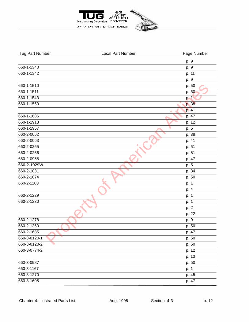
Tug Part Number Local Part Number Page Number
Chapter 4: Illustrated Parts List Aug. 1995 Section 4-3 p. 12
p. 9
660-1-1340 p. 9
660-1-1342 p. 11
p. 9
660-1-1510 p. 50
660-1-1511 p. 50
660-1-1543 p. 1
660-1-1550 p. 38
p. 41
660-1-1686 p. 47
660-1-1913 p. 12
660-1-1957 p. 5
660-2-0062 p. 38
660-2-0063 p. 41
660-2-0265 p. 51
660-2-0266 p. 51
660-2-0958 p. 47
660-2-1029W p. 5
660-2-1031 p. 34
660-2-1074 p. 50
660-2-1103 p. 1
p. 4
660-2-1229 p. 1
660-2-1230 p. 1
p. 2
p. 22
660-2-1278 p. 9
660-2-1360 p. 50
660-2-1685 p. 47
660-3-0120-1 p. 50
660-3-0120-2 p. 50
660-3-0774-2 p. 12
p. 13
660-3-0987 p. 50
660-3-1167 p. 1
660-3-1270 p. 45
660-3-1605 p. 47
Prope
rty o
f Am
erica
n Airli
nes
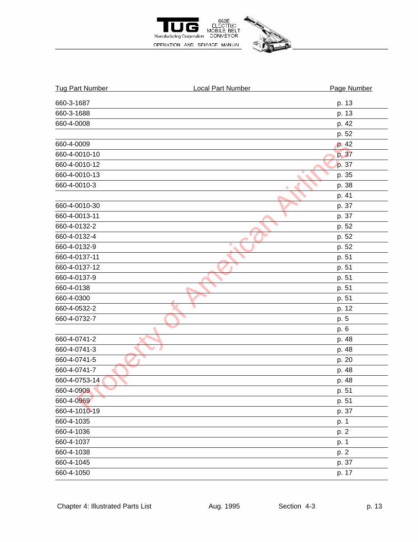
Tug Part Number Local Part Number Page Number
Chapter 4: Illustrated Parts List Aug. 1995 Section 4-3 p. 13
660-3-1687 p. 13
660-3-1688 p. 13
660-4-0008 p. 42
p. 52
660-4-0009 p. 42
660-4-0010-10 p. 37
660-4-0010-12 p. 37
660-4-0010-13 p. 35
660-4-0010-3 p. 38
p. 41
660-4-0010-30 p. 37
660-4-0013-11 p. 37
660-4-0132-2 p. 52
660-4-0132-4 p. 52
660-4-0132-9 p. 52
660-4-0137-11 p. 51
660-4-0137-12 p. 51
660-4-0137-9 p. 51
660-4-0138 p. 51
660-4-0300 p. 51
660-4-0532-2 p. 12
660-4-0732-7 p. 5
p. 6
660-4-0741-2 p. 48
660-4-0741-3 p. 48
660-4-0741-5 p. 20
660-4-0741-7 p. 48
660-4-0753-14 p. 48
660-4-0909 p. 51
660-4-0969 p. 51
660-4-1010-19 p. 37
660-4-1035 p. 1
660-4-1036 p. 2
660-4-1037 p. 1
660-4-1038 p. 2
660-4-1045 p. 37
660-4-1050 p. 17
Prope
rty o
f Am
erica
n Airli
nes
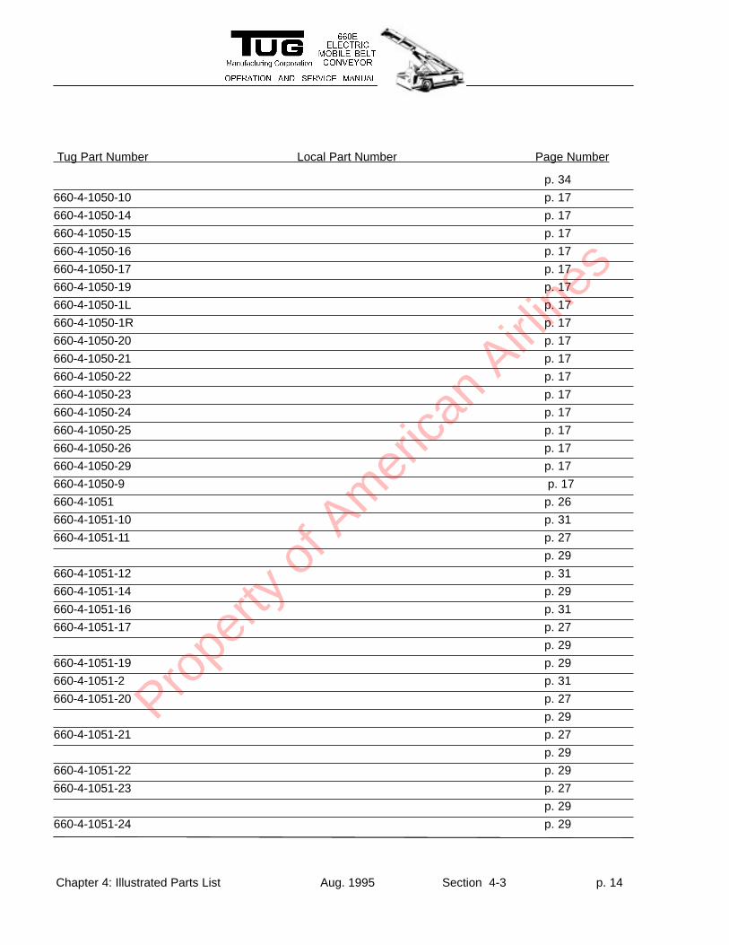
Tug Part Number Local Part Number Page Number
Chapter 4: Illustrated Parts List Aug. 1995 Section 4-3 p. 14
p. 34
660-4-1050-10 p. 17
660-4-1050-14 p. 17
660-4-1050-15 p. 17
660-4-1050-16 p. 17
660-4-1050-17 p. 17
660-4-1050-19 p. 17
660-4-1050-1L p. 17
660-4-1050-1R p. 17
660-4-1050-20 p. 17
660-4-1050-21 p. 17
660-4-1050-22 p. 17
660-4-1050-23 p. 17
660-4-1050-24 p. 17
660-4-1050-25 p. 17
660-4-1050-26 p. 17
660-4-1050-29 p. 17
660-4-1050-9 p. 17
660-4-1051 p. 26
660-4-1051-10 p. 31
660-4-1051-11 p. 27
p. 29
660-4-1051-12 p. 31
660-4-1051-14 p. 29
660-4-1051-16 p. 31
660-4-1051-17 p. 27
p. 29
660-4-1051-19 p. 29
660-4-1051-2 p. 31
660-4-1051-20 p. 27
p. 29
660-4-1051-21 p. 27
p. 29
660-4-1051-22 p. 29
660-4-1051-23 p. 27
p. 29
660-4-1051-24 p. 29
Prope
rty o
f Am
erica
n Airli
nes
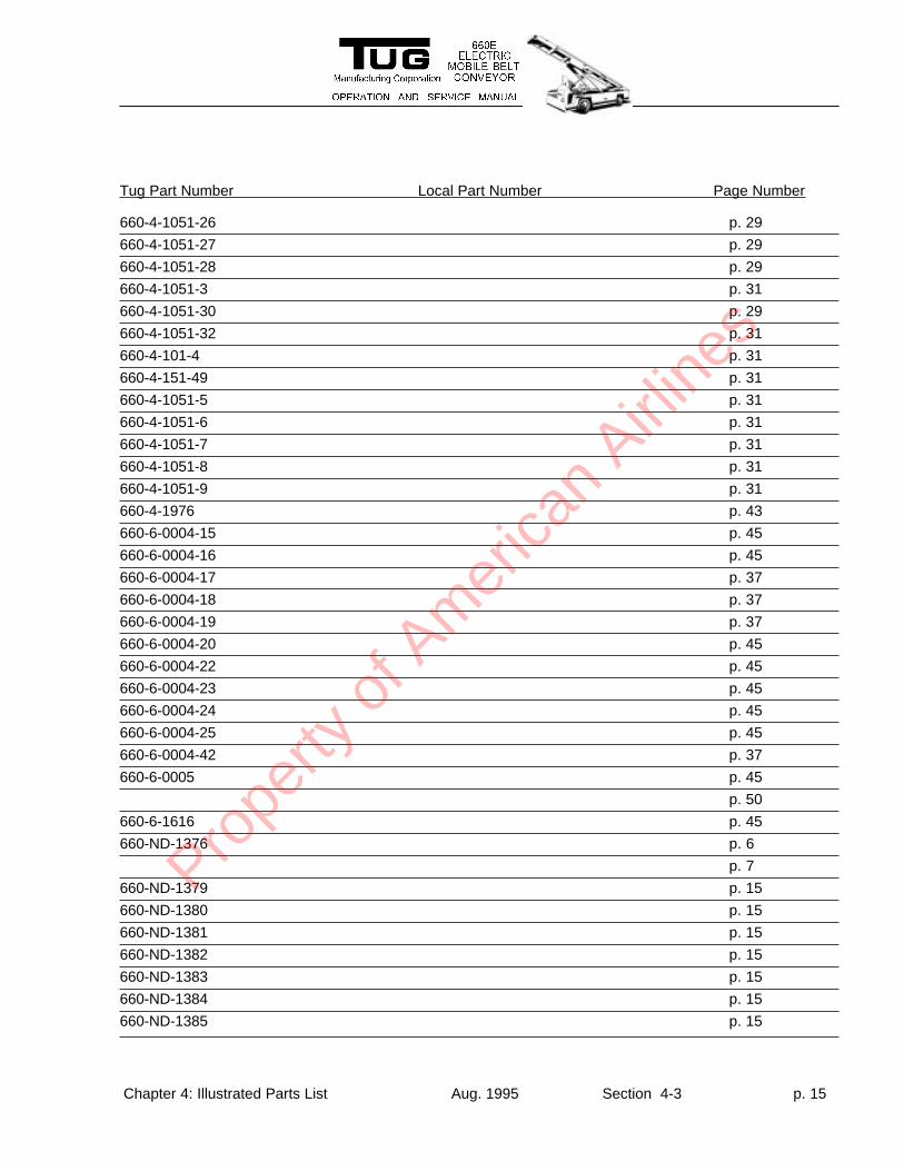
Tug Part Number Local Part Number Page Number
Chapter 4: Illustrated Parts List Aug. 1995 Section 4-3 p. 15
660-4-1051-26 p. 29
660-4-1051-27 p. 29
660-4-1051-28 p. 29
660-4-1051-3 p. 31
660-4-1051-30 p. 29
660-4-1051-32 p. 31
660-4-101-4 p. 31
660-4-151-49 p. 31
660-4-1051-5 p. 31
660-4-1051-6 p. 31
660-4-1051-7 p. 31
660-4-1051-8 p. 31
660-4-1051-9 p. 31
660-4-1976 p. 43
660-6-0004-15 p. 45
660-6-0004-16 p. 45
660-6-0004-17 p. 37
660-6-0004-18 p. 37
660-6-0004-19 p. 37
660-6-0004-20 p. 45
660-6-0004-22 p. 45
660-6-0004-23 p. 45
660-6-0004-24 p. 45
660-6-0004-25 p. 45
660-6-0004-42 p. 37
660-6-0005 p. 45
p. 50
660-6-1616 p. 45
660-ND-1376 p. 6
p. 7
660-ND-1379 p. 15
660-ND-1380 p. 15
660-ND-1381 p. 15
660-ND-1382 p. 15
660-ND-1383 p. 15
660-ND-1384 p. 15
660-ND-1385 p. 15
Prope
rty o
f Am
erica
n Airli
nes
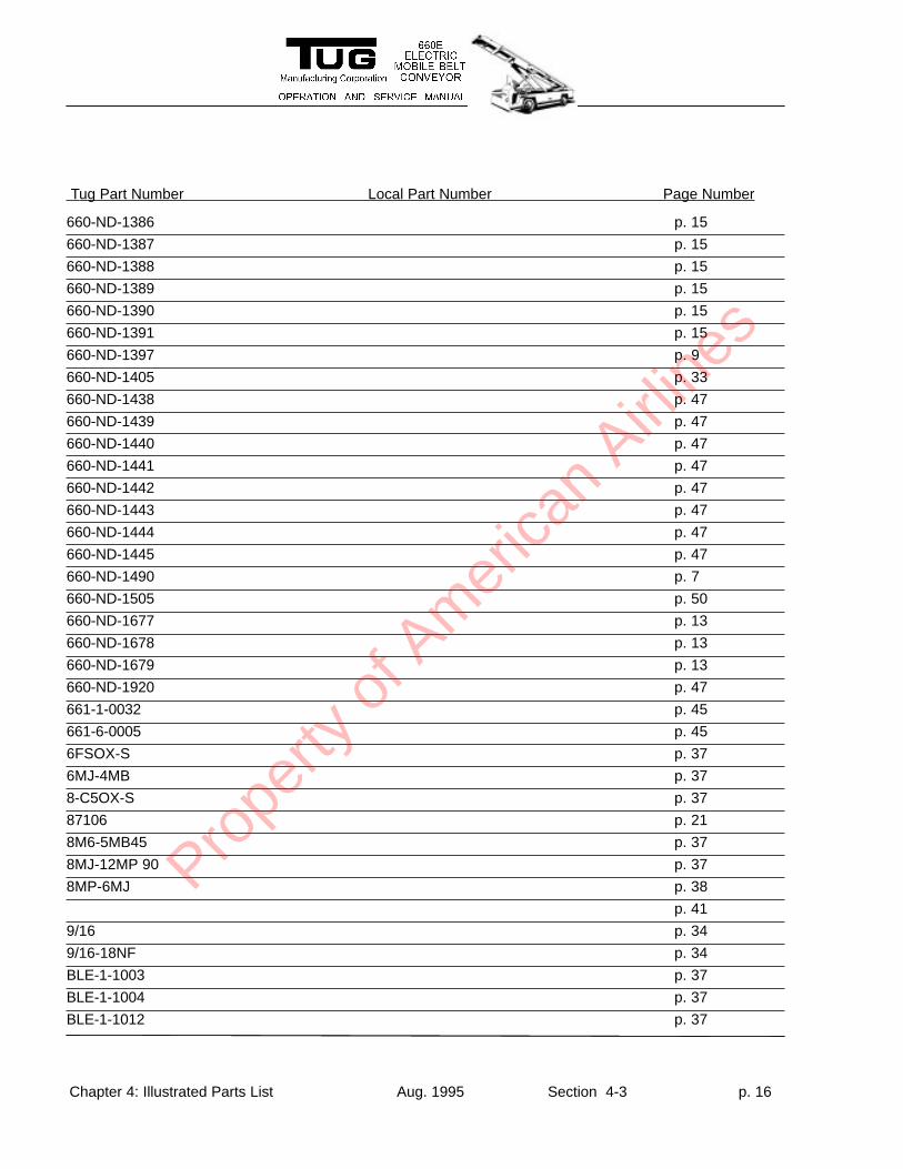
Tug Part Number Local Part Number Page Number
Chapter 4: Illustrated Parts List Aug. 1995 Section 4-3 p. 16
660-ND-1386 p. 15
660-ND-1387 p. 15
660-ND-1388 p. 15
660-ND-1389 p. 15
660-ND-1390 p. 15
660-ND-1391 p. 15
660-ND-1397 p. 9
660-ND-1405 p. 33
660-ND-1438 p. 47
660-ND-1439 p. 47
660-ND-1440 p. 47
660-ND-1441 p. 47
660-ND-1442 p. 47
660-ND-1443 p. 47
660-ND-1444 p. 47
660-ND-1445 p. 47
660-ND-1490 p. 7
660-ND-1505 p. 50
660-ND-1677 p. 13
660-ND-1678 p. 13
660-ND-1679 p. 13
660-ND-1920 p. 47
661-1-0032 p. 45
661-6-0005 p. 45
6FSOX-S p. 37
6MJ-4MB p. 37
8-C5OX-S p. 37
87106 p. 21
8M6-5MB45 p. 37
8MJ-12MP 90 p. 37
8MP-6MJ p. 38
p. 41
9/16 p. 34
9/16-18NF p. 34
BLE-1-1003 p. 37
BLE-1-1004 p. 37
BLE-1-1012 p. 37
Prope
rty o
f Am
erica
n Airli
nes
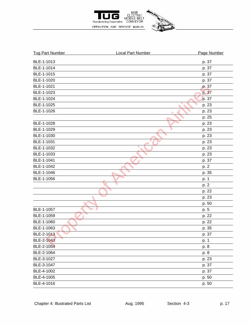
Tug Part Number Local Part Number Page Number
Chapter 4: Illustrated Parts List Aug. 1995 Section 4-3 p. 17
BLE-1-1013 p. 37
BLE-1-1014 p. 37
BLE-1-1015 p. 37
BLE-1-1020 p. 37
BLE-1-1021 p. 37
BLE-1-1023 p. 37
BLE-1-1024 p. 37
BLE-1-1025 p. 23
BLE-1-1026 p. 23
p. 25
BLE-1-1028 p. 23
BLE-1-1029 p. 23
BLE-1-1030 p. 23
BLE-1-1031 p. 23
BLE-1-1032 p. 23
BLE-1-1033 p. 23
BLE-1-1041 p. 37
BLE-1-1042 p. 2
BLE-1-1046 p. 35
BLE-1-1056 p. 1
p. 2
p. 22
p. 23
p. 50
BLE-1-1057 p. 5
BLE-1-1059 p. 22
BLE-1-1060 p. 22
BLE-1-1063 p. 35
BLE-2-1013 p. 37
BLE-2-1043 p. 1
BLE-2-1054 p. 8
BLE-2-1064 p. 8
BLE-3-1027 p. 23
BLE-3-1047 p. 37
BLE-4-1002 p. 37
BLE-4-1005 p. 50
BLE-4-1016 p. 50
Prope
rty o
f Am
erica
n Airli
nes
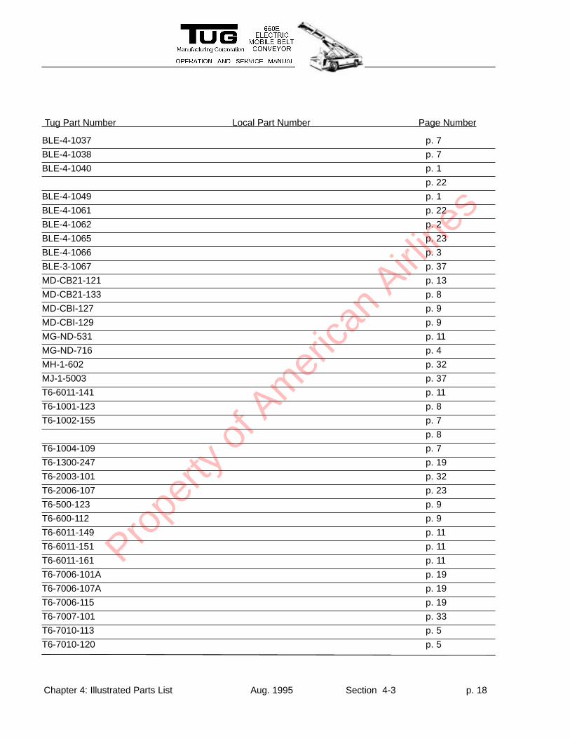
Tug Part Number Local Part Number Page Number
Chapter 4: Illustrated Parts List Aug. 1995 Section 4-3 p. 18
BLE-4-1037 p. 7
BLE-4-1038 p. 7
BLE-4-1040 p. 1
p. 22
BLE-4-1049 p. 1
BLE-4-1061 p. 22
BLE-4-1062 p. 2
BLE-4-1065 p. 23
BLE-4-1066 p. 3
BLE-3-1067 p. 37
MD-CB21-121 p. 13
MD-CB21-133 p. 8
MD-CBI-127 p. 9
MD-CBI-129 p. 9
MG-ND-531 p. 11
MG-ND-716 p. 4
MH-1-602 p. 32
MJ-1-5003 p. 37
T6-6011-141 p. 11
T6-1001-123 p. 8
T6-1002-155 p. 7
p. 8
T6-1004-109 p. 7
T6-1300-247 p. 19
T6-2003-101 p. 32
T6-2006-107 p. 23
T6-500-123 p. 9
T6-600-112 p. 9
T6-6011-149 p. 11
T6-6011-151 p. 11
T6-6011-161 p. 11
T6-7006-101A p. 19
T6-7006-107A p. 19
T6-7006-115 p. 19
T6-7007-101 p. 33
T6-7010-113 p. 5
T6-7010-120 p. 5
Prope
rty o
f Am
erica
n Airli
nes
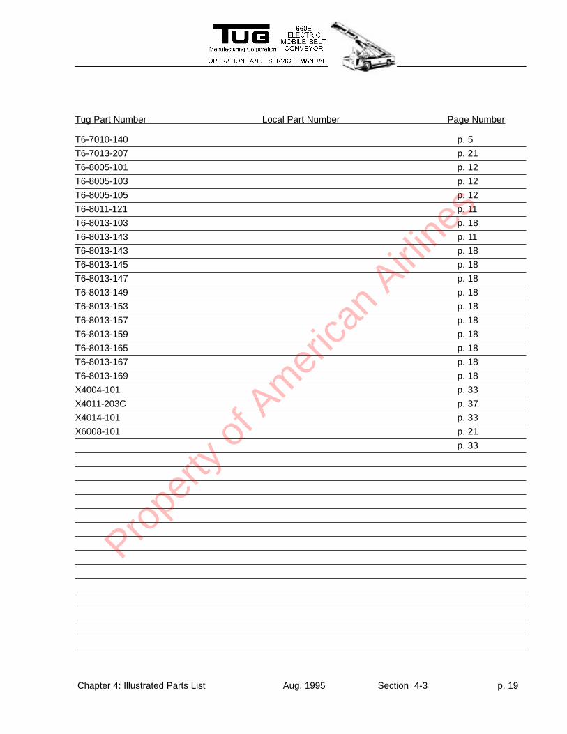
Tug Part Number Local Part Number Page Number
Chapter 4: Illustrated Parts List Aug. 1995 Section 4-3 p. 19
T6-7010-140 p. 5
T6-7013-207 p. 21
T6-8005-101 p. 12
T6-8005-103 p. 12
T6-8005-105 p. 12
T6-8011-121 p. 11
T6-8013-103 p. 18
T6-8013-143 p. 11
T6-8013-143 p. 18
T6-8013-145 p. 18
T6-8013-147 p. 18
T6-8013-149 p. 18
T6-8013-153 p. 18
T6-8013-157 p. 18
T6-8013-159 p. 18
T6-8013-165 p. 18
T6-8013-167 p. 18
T6-8013-169 p. 18
X4004-101 p. 33
X4011-203C p. 37
X4014-101 p. 33
X6008-101 p. 21
p. 33
Prope
rty o
f Am
erica
n Airli
nes
Tug Part Number Local Part Number Page Number
Chapter 4: Illustrated Parts List Aug. 1995 Section 4-3 p. 20
Prope
rty o
f Am
erica
n Airli
nes


