AGA/AOP/SG/8 — WP/14 International Civil Aviation Organization Revised 19/07/11 Regional CAR/SAM Planning and Implementation Group (GREPECAS) Meeting of the Aerodromes and Ground Aids/Aerodrome Operational Planning Subgroup of GREPECAS (AGA/AOP/SG/8) Mexico City, Mexico, 19 to 21 July 2011 Agenda Item 5: Other business PROPOSAL OF AMENDMENT TO DOC 9157, AERODROME DESIGN MANUAL, PART 4, VISUAL AIDS, CORRESPONDING TO THE GUIDELINES ON THE APPLICATION OF AIRCRAFT STAND MARKINGS (Presented by Uruguay) SUMMARY The SARPs in Annex 14 Volume I, Aerodrome Design and Operations, and Doc 9157, Aerodrome Design Manual, Part 4, Visual Aids, with a view to strengthening safety, recommend the incorporation of initiatives to improve safe aircraft operations on the apron area and thus enhance safety on the movement area. These initiatives would be introduced as recommendations in Doc 9157, Aerodrome Design Manual, Part 4, Visual Aids, Aircraft stand markings – for their corresponding application by States. References: • ICAO Annex 14 Volume I, Aerodrome Design and Operations • ICAO Doc 9157, Aerodrome Design Manual, Part 4, Visual Aids • Manual Normativo de Señalización en el Área de Movimiento (AENA) ICAO Strategic objectives: Safety 1. 2. Introduction 2.1 Annex 14 Volume I, Aerodrome Design and Operations, and Doc 9157, Part 4, Visual Aids, 1.2.13 Aircraft stand markings – Application, location and characteristics of these markings, contain guidance on the layout of aircraft stand markings. See also 2.3, Apron markings, Objective of aircraft stand guidance. 2.2 In order to improve aircraft safety on the apron area, it is recommended that graphical solutions or explanatory illustrations be used in Doc 9157, Aerodrome Design Manual, Part 4, with a view to harmonising the use of apron markings by the States.
Transcript
AGA/AOP/SG/8 — WP/14International Civil Aviation Organization Revised 19/07/11Regional CAR/SAM Planning and Implementation Group (GREPECAS) Meeting of the Aerodromes and Ground Aids/Aerodrome Operational Planning Subgroup of GREPECAS (AGA/AOP/SG/8) Mexico City, Mexico, 19 to 21 July 2011
Agenda Item 5: Other business
PROPOSAL OF AMENDMENT TO DOC 9157, AERODROME DESIGN MANUAL, PART 4,
VISUAL AIDS, CORRESPONDING TO THE GUIDELINES ON THE APPLICATION OF AIRCRAFT STAND MARKINGS
(Presented by Uruguay)
SUMMARY
The SARPs in Annex 14 Volume I, Aerodrome Design and Operations, and Doc 9157, Aerodrome Design Manual, Part 4, Visual Aids, with a view to strengthening safety, recommend the incorporation of initiatives to improve safe aircraft operations on the apron area and thus enhance safety on the movement area. These initiatives would be introduced as recommendations in Doc 9157, Aerodrome Design Manual, Part 4, Visual Aids, Aircraft stand markings – for their corresponding application by States. References: • ICAO Annex 14 Volume I, Aerodrome Design and Operations • ICAO Doc 9157, Aerodrome Design Manual, Part 4, Visual Aids • Manual Normativo de Señalización en el Área de Movimiento (AENA) ICAO Strategic objectives: Safety
1. 2. Introduction 2.1 Annex 14 Volume I, Aerodrome Design and Operations, and Doc 9157, Part 4, Visual Aids, 1.2.13 Aircraft stand markings – Application, location and characteristics of these markings, contain guidance on the layout of aircraft stand markings. See also 2.3, Apron markings, Objective of aircraft stand guidance. 2.2 In order to improve aircraft safety on the apron area, it is recommended that graphical solutions or explanatory illustrations be used in Doc 9157, Aerodrome Design Manual, Part 4, with a view to harmonising the use of apron markings by the States.
AGA/AOP/SG/8 — WP/14 — 2 —
3. Discussion 3.1 The standards and recommended practices (SARPs) contained in Annex 14 Volume I Aerodrome Design and Operations, and the guidelines contained in Doc 9157, Aerodrome Design Manual, Part 4, do not provide much guidance on aircraft stand markings. In order to optimise aerodrome apron capacity, it is recommended that existing texts be modified, incorporating the texts and illustrations proposed in Annex A to this working paper. 4. Suggested action 4.1 The Meeting is invited to take note of the information provided in this paper and to make comments on the proposal of amendment to Doc 9157, Aerodrome Design Manual, Part 4, Visual Aids.
— - - - —
AGA/AOP/SG/8 WP/14
APPENDIX A
Proposal of Amendment to Annex 14, Introducing Recommendations on Taxiway Edge
Markings
1. Aircraft stand markings
1.1. Aircraft stand markings shall be provided for designated parking positions on a paved apron.
1.2. Aircraft stand markings on a paved apron shall be located so as to provide the
clearances specified when the nose wheel follows the stand marking. 1.3. Aircraft stand markings shall include such elements as stand identification, lead-
in line, turn bar, turning line, alignment bar, stop line and lead-out line, as are required by the parking configuration and to complement other parking aids.
1.4. An aircraft stand identification (letter or number) shall be included in the lead-in
line a short distance after the beginning of the lead-in line. The height of the identification should be adequate to be readable from the cockpit of aircraft using the stand.
1.5. Where two sets of aircraft stand markings are superimposed on each other in
order to permit more flexible use of the apron and thus increase its capacity, then identification of the aircraft for which each set of markings is intended should be added to the stand marking.
1.6. Example: 2A-B747, 2B-F28. Lead-in, turning and lead-out lines shall be
continuous in length and have a width of not less than 11 cm. Where one or more sets of stand markings are superimposed on a stand marking, the lines should be continuous for the most frequent aircraft and broken for other aircraft.
1.7. The curved portions of lead-in, turning and lead-out lines should have radii
appropriate to the most demanding aircraft type for which the markings are intended.
1.8. Where it is intended that an aircraft proceed in one direction only, arrows
pointing in the direction to be followed should be added as part of the lead-in and lead-out lines.
1.9. A turn bar should be located at right angles to the lead-in line, abeam the left pilot
position at the point of initiation of any intended turn. It should have a length and width of not less than 6 cm and 11 cm, respectively, and include an arrowhead to indicate the direction of turn.
A2 AGA/AOP/SG/8 WP/14
1.10. The distances to be maintained between the turn bar and the lead-in line may vary according to different aircraft types, taking into account the pilot’s field of view.
1.11. If more than one turn bar or stop line is required, they shall be coded. 1.12. An alignment bar should be placed so as to be coincident with the extended centre
line of the aircraft in the specified parking position and visible to the pilot during the final part of the parking manoeuvre. It shall have a width of not less than 11 cm.
1.13. A stop line shall be located at right angles to the alignment bar, abeam the left
pilot position at the intended point of stop. It shall have a length and width of not less than 6 m and 11 cm, respectively.
1.14. The distances to be maintained between the stop line and the lead-in line may
vary according to different aircraft types, taking into account the pilot’s field of view.
2. Apron taxiway centre line marking and apron edge marking
2.1. The apron taxiway centre line marking will provide guidance for taxiing to the
point on the apron where aircraft stand markings begin. The taxiway centre line marking will be a continuous yellow line, 20 cm wide, with a 10-cm black border. Fig. 1-11-1.
Figure 1-11-1 – Apron taxiway centre line marking (TCL)
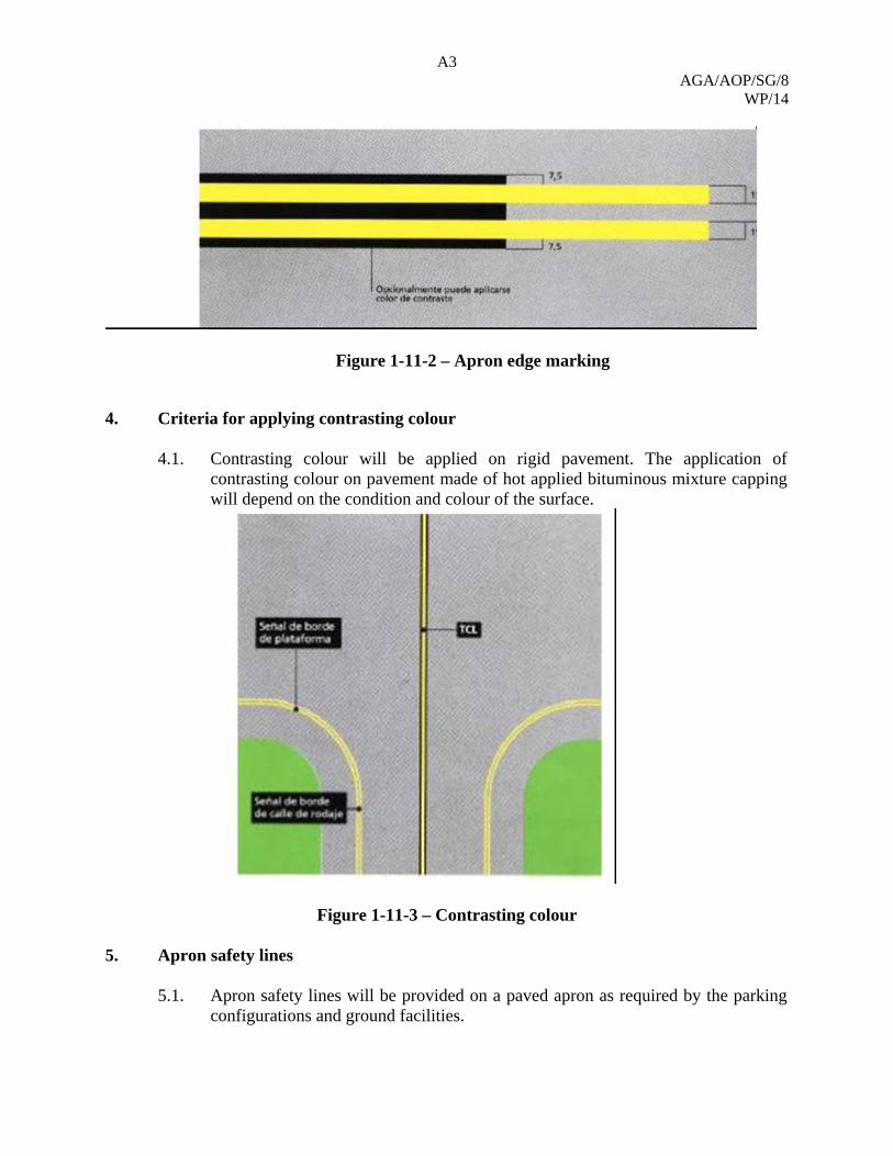
3. Apron edge marking 3.1. The apron edge marking will delimit the load-bearing apron surface. It is the
extension of the taxiway edge marking. This marking may be delineated in accordance with pavement contrast. Fig. 1-11-2.
A3 AGA/AOP/SG/8
WP/14
Figure 1-11-2 – Apron edge marking
4. Criteria for applying contrasting colour
4.1. Contrasting colour will be applied on rigid pavement. The application of
contrasting colour on pavement made of hot applied bituminous mixture capping will depend on the condition and colour of the surface.
5.1. Apron safety lines will be provided on a paved apron as required by the parking configurations and ground facilities.
A4 AGA/AOP/SG/8 WP/14
5.2. Apron safety lines shall be located so as to define the areas intended for use by ground vehicles and other aircraft servicing equipment, to provide safe separation from aircraft.
5.3. Apron safety lines will include such elements as wing tip clearance lines and service road boundary lines as required by the parking configurations and ground facilities.
5.4. An apron safety line should be continuous in length and at least 10 cm in width. 5.5. The line will delimit the aircraft movement area (i.e., apron taxiways and access
to parking positions) and will separate it from those areas intended for other purposes and which may contain obstacles for aircraft (parking positions, equipment parking or storage area). Fig. 1-11-4, 11-5, 11-6, -11-7.
6. Equipment restriction area (ERL) marking
6.1. The marking will delimit an equipment restriction area (ERA) or aircraft stand. This area will be designated as aircraft safety area (ASA).
6.2. The equipment restriction area/aircraft safety area (ERA/ASA) is defined as the area in which the aircraft is parked and serviced by ground handling vehicles.
6.3. During the aircraft entry manoeuvre, the ERA/ASA must be clear of vehicles, equipment and persons, who should be at least 7.1 m (4.1 m in some cases) from the aircraft.
6.4. The equipment holding area will be an area established at a safe distance from the parked aircraft to keep handling teams until the aircraft has completed the manoeuvre for entering the parking position.
6.5. No vehicles, equipment or persons must enter the ERA/ASA, except for those absolutely needed for conducting the manoeuvre, until the aircraft has come to a stop, shut off the engines, turned off collision avoidance lights, and chocks have been installed.
6.6. The aircraft handling process is conducted “inside” the ERA/ASA and the ESA (equipment staging area) associated to the stand.
6.7. The use of adjacent ERA/ASAs and any defined no parking area (NPA), as well as taxiways adjacent to the stand, for equipment staging shall be avoided.
6.8. For exiting aircraft, both the ERA/ASA as well as the ESAs associated to the stand must be clear of equipment and persons, except for those absolutely needed for the manoeuvre. For superimposed stands for different types of aircraft, see Fig. 1-11-8.
7. Equipment staging area (ESL) marking
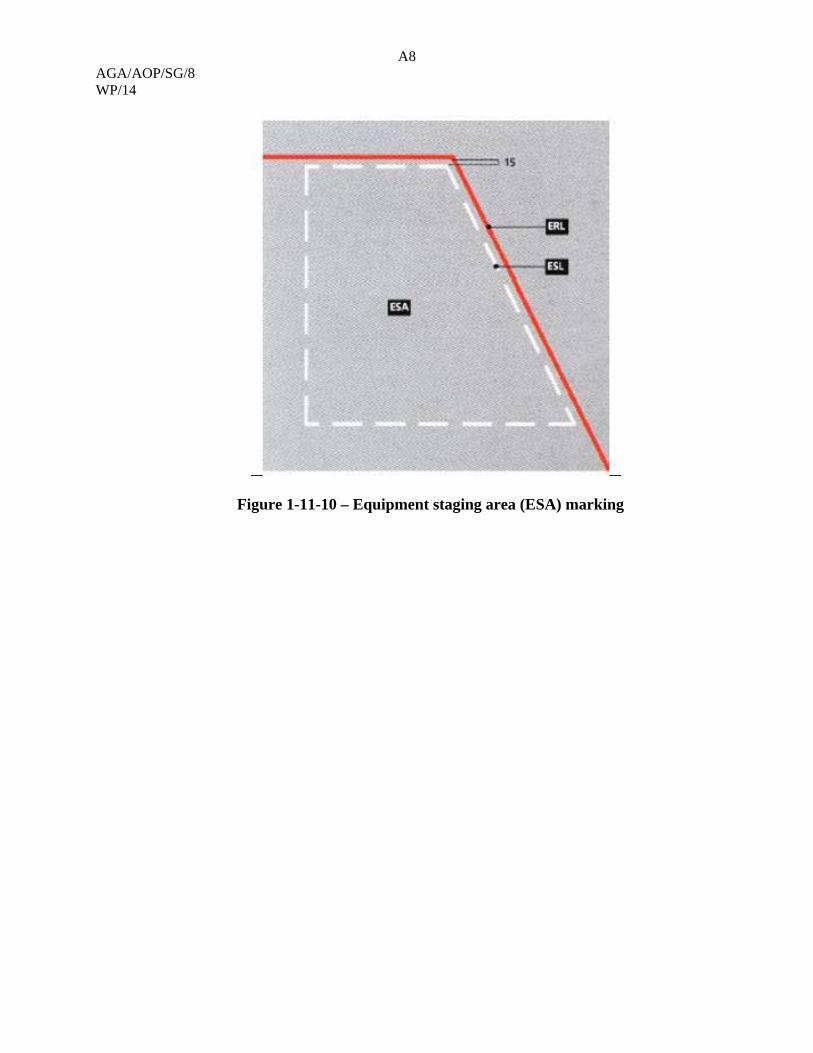
7.1. The equipment staging marking will delimit an equipment staging area (ESA), if
any. Outlined in accordance with the area it delimits. Fig. 1-11-9 and 11-10.
8. Equipment parking area (EPL) marking
A5 AGA/AOP/SG/8
WP/14
8.1. The equipment parking marking delimits an equipment parking area (EPA). This area may only be accessed through the dotted line. Outlined in accordance with the area it delimits. Fig. 1-11-11.
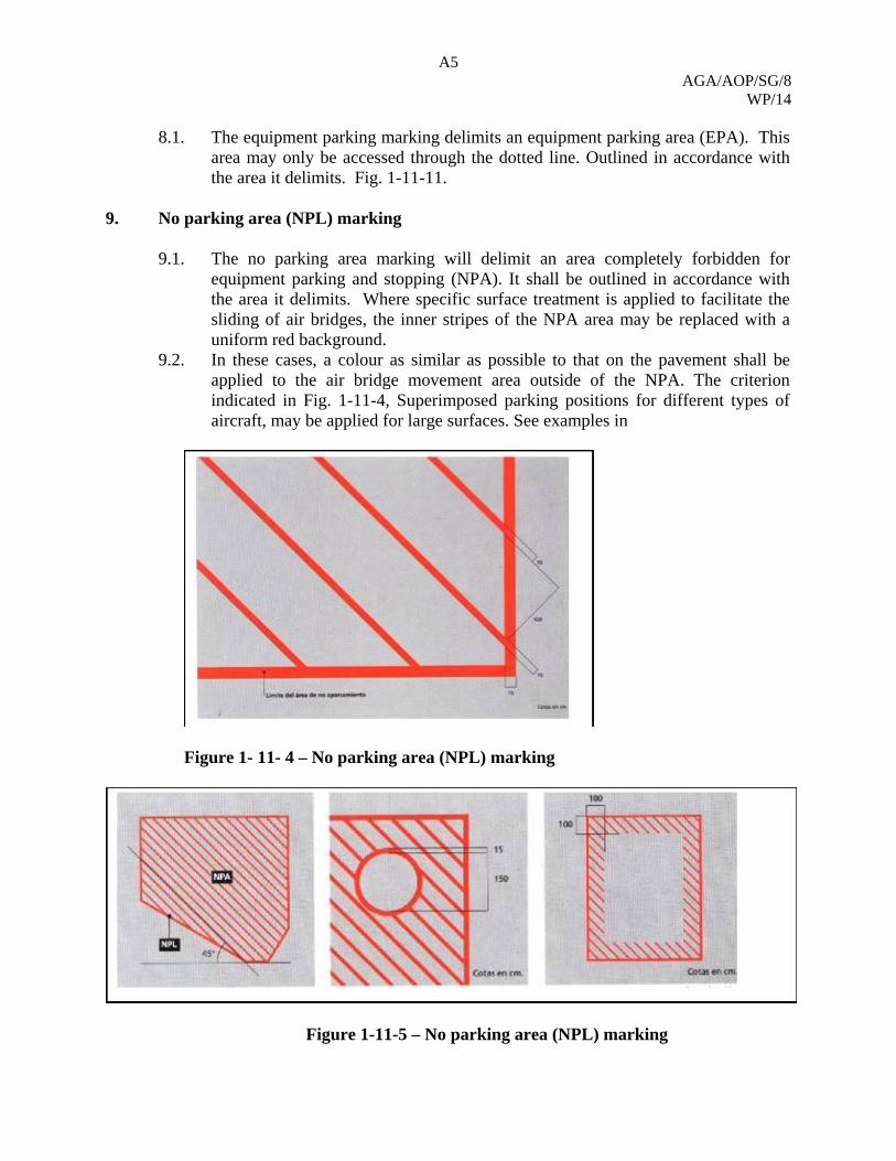
9. No parking area (NPL) marking
9.1. The no parking area marking will delimit an area completely forbidden for
equipment parking and stopping (NPA). It shall be outlined in accordance with the area it delimits. Where specific surface treatment is applied to facilitate the sliding of air bridges, the inner stripes of the NPA area may be replaced with a uniform red background.
9.2. In these cases, a colour as similar as possible to that on the pavement shall be applied to the air bridge movement area outside of the NPA. The criterion indicated in Fig. 1-11-4, Superimposed parking positions for different types of aircraft, may be applied for large surfaces. See examples in
Figure 1- 11- 4 – No parking area (NPL) marking
Figure 1-11-5 – No parking area (NPL) marking
A6 AGA/AOP/SG/8 WP/14
Figure 1-11-6 – Apron safety line (ABL)
Figure 1-11-7 - Apron safety line (ABL) and colour contrast
A7 AGA/AOP/SG/8
WP/14
Figure 1-11- 8 – Equipment restriction area (ERA)/aircraft safety area (ASA)
Figure 1-11-9 – Equipment staging area (ESL) marking
A8 AGA/AOP/SG/8 WP/14
Figure 1-11-10 – Equipment staging area (ESA) marking
A9 AGA/AOP/SG/8
WP/14
Figure 1-11-11 – Equipment staging area (EPA) marking
10. Aircraft stand directional marking
10.1. The marking will indicate to the pilot of the aircraft the direction to be followed
to get to the assigned stand. See Fig. 1-11-12.
A10 AGA/AOP/SG/8 WP/14
Figure 1-11-12 – Aircraft stand directional marking
A11 AGA/AOP/SG/8
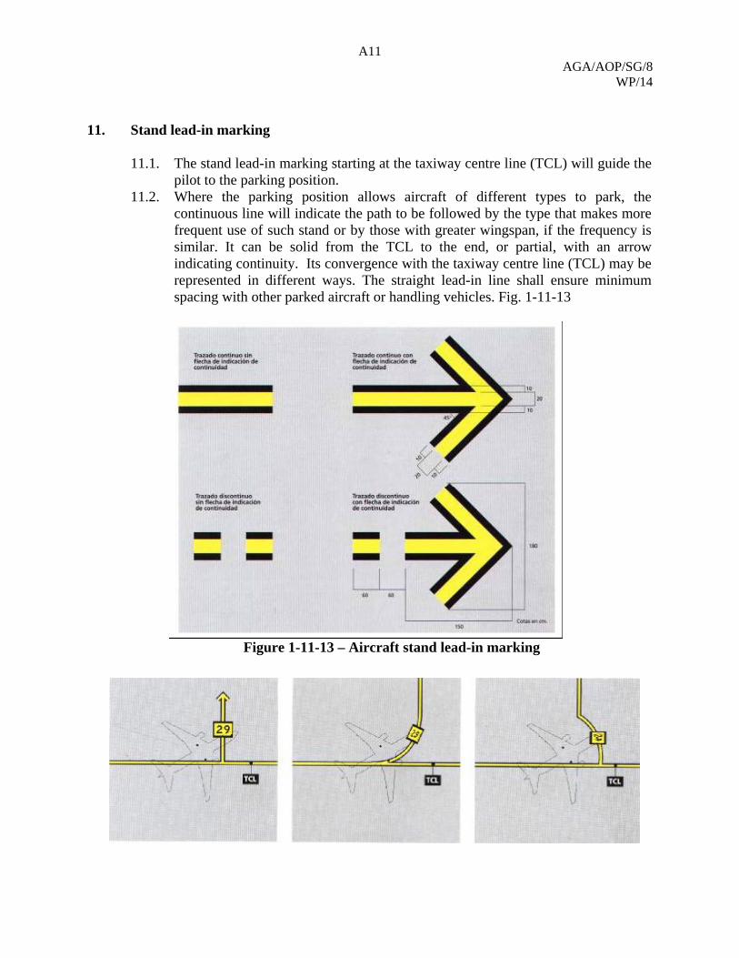
WP/14 11. Stand lead-in marking
11.1. The stand lead-in marking starting at the taxiway centre line (TCL) will guide the
pilot to the parking position. 11.2. Where the parking position allows aircraft of different types to park, the
continuous line will indicate the path to be followed by the type that makes more frequent use of such stand or by those with greater wingspan, if the frequency is similar. It can be solid from the TCL to the end, or partial, with an arrow indicating continuity. Its convergence with the taxiway centre line (TCL) may be represented in different ways. The straight lead-in line shall ensure minimum spacing with other parked aircraft or handling vehicles. Fig. 1-11-13
Figure 1-11-13 – Aircraft stand lead-in marking
A12 AGA/AOP/SG/8 WP/14 12. Parking position identification in lead-in marking
12.1. The designation of the parking position is indicated in the lead-in line.
Where aircraft can taxi from two directions to the parking position, the indicated characters shall be used. Where aircraft can taxi from a single direction to the parking position, the identification will be as shown in Fig. 1-11-14,11-11, 11-16 and the characters shown in the Appendix shall be used. The use of two different types of characters for these markings is determined by legibility criteria: if the pilot can read the marking from both directions, the type indicated in Fig. 1-11-14-A, which does not have longitudinal distortion, is more legible. If, on the other hand, it must always be read from one same direction, the type indicated in Fig. 1-11-14-B, which has distortion in the direction in which the aircraft is moving, is more legible.
Figure 1-11-14 A Identification of parking position on lead-in marking
A13 AGA/AOP/SG/8
WP/14
Figure 1-11-14-B Identification of parking position on lead-in marking
Figure 1-11-11 – Identification of parking position on lead-in marking
Figure 1-11-16 – Parking positions with a single taxiing direction to the stand
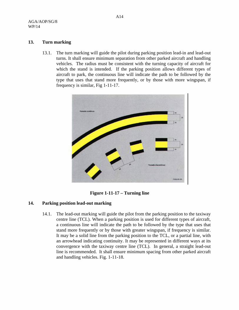
A14 AGA/AOP/SG/8 WP/14 13. Turn marking
13.1. The turn marking will guide the pilot during parking position lead-in and lead-out
turns. It shall ensure minimum separation from other parked aircraft and handling vehicles. The radius must be consistent with the turning capacity of aircraft for which the stand is intended. If the parking position allows different types of aircraft to park, the continuous line will indicate the path to be followed by the type that uses that stand more frequently, or by those with more wingspan, if frequency is similar, Fig 1-11-17.
Figure 1-11-17 – Turning line
14. Parking position lead-out marking
14.1. The lead-out marking will guide the pilot from the parking position to the taxiway centre line (TCL). When a parking position is used for different types of aircraft, a continuous line will indicate the path to be followed by the type that uses that stand more frequently or by those with greater wingspan, if frequency is similar. It may be a solid line from the parking position to the TCL, or a partial line, with an arrowhead indicating continuity. It may be represented in different ways at its convergence with the taxiway centre line (TCL). In general, a straight lead-out line is recommended. It shall ensure minimum spacing from other parked aircraft and handling vehicles. Fig. 1-11-18.
A15 AGA/AOP/SG/8
WP/14
Figure 1-11-18 – Parking position lead-out marking
15. Turn bar marking
15.1. Indicates where the turn starts, abeam the cockpit (must be placed so as to be visible from the pilot’s seat) Fig.1-11-19.
15.2. Will be located to the left side looking forward, at right angles to the guide lines, with the arrowhead indicating to the direction of the turn.
15.3. According to the aircraft fleet being operated, it may be necessary to paint more than one, although the number of markings must be keep to a minimum.
Figure 1-11-19 Turn bar marking
A16 AGA/AOP/SG/8 WP/14
16. Stop bar marking
16.1. The distance between the beginning of the stop bar marking and the parking position centre line shall be such that the stand designation and the stop bar are visible from the cockpit of the aircraft when properly parked.
17. Aircraft stopping positions
17.1. The stop bar will indicate the pilot where to stop, and must be placed
perpendicular to the cabin. This indication is valid only when the aircraft proceeds directly to the parking position without any guidance, whether automatic or from a signalman. In those cases in which external assistance is used, it is not valid as a reference, and varies according to the position, whether air bridge or remote. In case of an air bridge position, the important thing is the position of the aircraft door to enable its connection at a suitable slope. This ideal position of the door defines for each aircraft the position where the nose wheel must come to rest, and is valid either when an automatic start-up system or a signalman is used. Precision requirements are very stringent for air bridges with two degrees of freedom, and much less stringent for air bridges with three degrees of freedom. Consequently, only the former requires marking with many nose wheel position bars, and in the latter case, aircraft may be grouped so that only three or four bars are needed.
A17 AGA/AOP/SG/8
WP/14
18. Positions
18.1. Instead of stop bars, nose wheel bars will be marked in air bridge positions, in
numbers that vary according to factors such as the number of degrees of freedom of air bridges, their margin of mobility and compliance with the appropriate slopes, and types of aircraft that use the air bridge more frequently.
18.2. In the case of remote positions, the important thing is to place the nose wheel so that minimum safety distances are observed where the aircraft is closest to an obstacle. For these positions, the aircraft is allowed to get to the position without guidance, reason why the stop bar must be marked. The use of a large number of stop bars may confuse pilots; therefore, an attempt should be made to place only one, corresponding to the most unfavourable aircraft, or two at the most. This means that nose wheels will end up in different positions, which must be marked so that the signalman may perform his function.
18.3. In remote positions, a stop bar (or two at the most, in extreme cases), corresponding to the most unfavourable aircraft in terms of compliance with minimum safety distances, shall be placed, as well as the nose wheel bars that are deemed advisable. However, when there is no risk of incidents for aircraft that will use the position, it will be enough to mark the stop bar and the nose wheel bar of the most frequent aircraft, recognising that, for the rest of the aircraft, the final position will differ depending on whether or not aircraft use guidance to reach the position (since the distance between the nose wheel and the cabin varies depending on the aircraft).
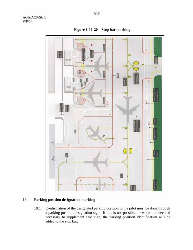
18.4. When several stop bars are marked in a stand, a text may be added to indicate to the pilot where to stop the aircraft. See Fig. 1-11-20.
A18 AGA/AOP/SG/8 WP/14
Figure 1-11-20 – Stop bar marking
19. Parking position designation marking
19.1. Confirmation of the designated parking position to the pilot must be done through a parking position designation sign. If this is not possible, or when it is deemed necessary to supplement said sign, the parking position identification will be added to the stop bar.
A19 AGA/AOP/SG/8
WP/14
19.2. In air bridge stands, the identification of the parking position should be readily visible from the cockpit when the aircraft is properly parked. In order to properly align the aircraft with the parking position centre line, there must be a straight segment of at least half the length of the aircraft following the lead-in turn.
19.3. In remote positions, the identification will be placed at the centre, at the end of the stop bar. See characters in Fig. 1-11-21, 11-22.
Figure 1-11-21 – Parking position designation marking
A20 AGA/AOP/SG/8 WP/14
A21 AGA/AOP/SG/8
WP/14
Figure 1-11-22 – Parking position designation marking
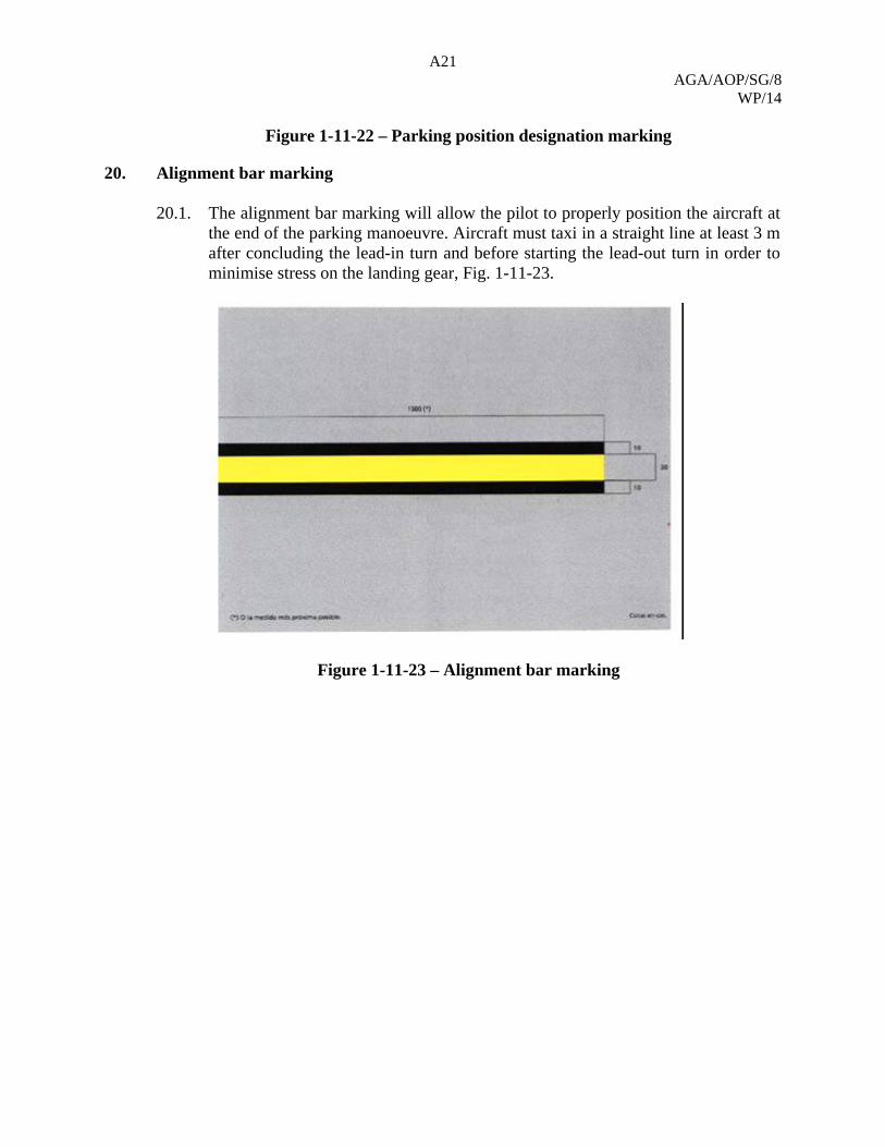
20. Alignment bar marking
20.1. The alignment bar marking will allow the pilot to properly position the aircraft at the end of the parking manoeuvre. Aircraft must taxi in a straight line at least 3 m after concluding the lead-in turn and before starting the lead-out turn in order to minimise stress on the landing gear, Fig. 1-11-23.
Figure 1-11-23 – Alignment bar marking
A22 AGA/AOP/SG/8 WP/14
21. Nose wheel bar marking and aircraft type indication
21.1. The nose wheel bar marking and the aircraft type indication will allow the pilot to
properly position the aircraft at the end of the parking manoeuvre. Fig. 1-11-25.
A23 AGA/AOP/SG/8
WP/14
Figure 1-11-25 – Nose wheel bar and aircraft type indication
22. Facility marking
22.1. The facility marking will indicate the location of apron facilities (hydrants, grounding connections, anchoring, etc.). The size of this marking will be consistent with the size of the facility it indicates, and will include an identification code. See Fig. 1-11-26.


![Draft proposal for Amendment [3] to regulation No. 94 (Frontal … · 2013-12-13 · Draft proposal for Amendment [3] to regulation No. 94 (Frontal Impact) The text reproduced below](https://static.documents.pub/doc/80x56/5e678761d04a63382d64e55a/draft-proposal-for-amendment-3-to-regulation-no-94-frontal-2013-12-13-draft.jpg)


