ANNEX: ............................................................................................ Error! Bookmark not defined.
ATTACHMENTS .............................................................................. Error! Bookmark not defined.
ENVIRONMENTAL ASSESSMENT OBJECTIVES AND SCOPE OF
WORK
Introduction
Vegpro Limited deals in fresh produce, flowers and logistics from Kenya. The company
operates two firms i.e. Gorge Farm and Longonot Farm in Naivasha located 15KM from Naivasha
town along Moi South Lake Road. Vegpro Ltd is a leading producer of vegetables and cut flowers.
After the fresh produce and flowers for export are produced, wastes such as spent vegetable, rose
plants (leaves, stems, etc.), vegetable out grades, rose rejects and farm produced “green crops” that
are left are first decomposed and used as fertilizer for the farm. These wastes will henceforth
collectively be referred to as feedstock.
Photo 2: Photo showing vegetables in the farm
Approximately 23,024 tonnes per year of fresh feedstock is available at a dry matter (DM) content of
23.7%, giving 5,448 tonnes per year of dry matter (DM). In order to utilize the feedstock and
diversify revenue sources, the company proposes to set up biogas plant within its Gorge farm, at the
south-western end, a spot which is about 200 meters from an existing KPLC sub-station. (see photo 1)
Photo 3: Photo Showing the process waste
used as feedstock
Photo 4: Photo showing sweet corn process
waste
Extensive testing of this material in laboratory scale digesters at Southampton University, UK, has
shown that this feedstock will yield 421M3/hr of biogas of which 232 M
3/hr will be methane. These
methane is used in electricity generation. Some of the electricity generated will be used for the
operation of the plant itself, on the farm with the balance being exported to the grid.
The project proposal is for an on-farm anaerobic digestion (AD) plant comprising a system of
hydrolysers and a digester to produce biogas, an engine driven electricity generating set (genset) and
other associated equipment to operate and manage the process. The whole project is designed to be
sited on a pre-leveled area on the farm. This project will establish an environmentally friendly and
sustainable form of electricity (and heat) production from the feedstock, also known as substrate once
loaded into the digestion system. The AD process uses naturally occurring bacteria and other
microbes to convert organic matter in the feedstock into:
• Biogas, which is an energy rich mixture of methane and carbon dioxide which is
suitable for use as a fuel to generate electricity and heat.
• Nutrient rich solid and liquid fertilisers to be used on the farm in place of purchased
chemical fertilisers.
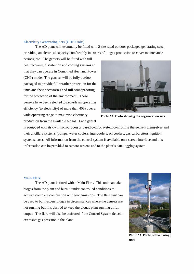
The resulting biogas is burned in an engine driven generating set (genset) to produce electricity,
mostly for use on the farm with the balance available for export to the grid. The genset also produces
heat in the form of engine cooling water and some of this will be used to heat the hydrolysers to 50-
55C and to maintain the digester at a temperature of ~ 40-45C. The pre-hydrolysis of the feedstock
material in the two hydrolysers ensures
significantly higher biogas production and
shorter residence times than conventional
AD plants, maximizing biological
degradation and stabilization, minimizing
capital costs and plant footprint and
increasing electricity (and heat)
production.
Photo 5: AD plant photo (the
surface tanks and with top
storage domes)
Photo 6: Standard Biogas generator set
It is recognized that projects such as the proposed biogas plant by Vegpro Limited could have
certain adverse environmental impacts if appropriate measures to protect the environment are
not undertaken. In order to ensure lasting co-existence of the site activities with other social and
economic activities in the area, and compliance with the Environmental Management and
Coordination Act, 1999, the site operators commissioned this environmental assessment for the
project.
Assessment Objectives
The objective of this assessment is to determine and assess the impacts of the proposed project and to
develop appropriate mitigation measures. The assessment also aims to ensure compliance with the
provisions of the Environmental Management and Coordination Act, 1999 and to prepare
an Environmental Management Plan which can be used as the basis for future audits.
Scope
The Kenya Government has put forward measures aimed at protecting the environment by listing
projects which must undergo environmental impact assessment under schedule 2 of EMCA 1999. For
a proposed project to get a license form NEMA, they are required to either submit a project or EIA
report depending on the magnitude and nature of the project. This EIA report covers the following
aspects of the proposed cogeneration project:
• The baseline environmental conditions of the area
• Description of the nature and design of the project
• Description of the major activities at the site during construction, operation and
decommissioning phases of the project
• Provisions of the relevant environmental laws
• Identification of materials to be used and by-products and wastes
• Identification and discussion of the potential adverse impacts to the environment from
the site
• Establish appropriate mitigation measures for these impacts
• Provision of an environmental management plan.
Terms of Reference
The terms of reference for the EIA included the following:
• Hold appropriate meetings with the management to establish the procedures, define
requirements, responsibilities, and a timeframe
• Provide a description of the nature, design, activities of the proposed Biogas Plant
with a focus on potential impacts to the surrounding environment
• Inspect the site and its surroundings in collaboration with the management
• Carry out a systematic environmental assessment at the site following the gazetted
regulations
• Conduct a stakeholder meeting for the identification of social and community
concerns
• Produce an environmental assessment project report that should contain among
other issues identification of key environmental aspects, recommendations on
appropriate mitigation measure to minimize or prevent adverse impacts and ensure
health and safety of the workers and neighbouring communities
• Develop an environmental management plan.
Responsibilities
While the environmental impact assessment expert provided the technical understanding on
the baseline environmental status, potential impacts, management options and legal framework,
the client provided the following:
• Site map(s) showing roads, service lines, buildings’ layout and the actual size of the
site
• Full details of nature of the project, design, materials usage and by-products, site
operational outline and any wastes to be generated
• Anticipated measures for handling wastes on the site
• Anticipated management programme for the proposed development
• Arrangement with surrounding community/stakeholder meetings
The output from the environmental expert included the following:
• An environmental impact assessment project report comprising of an executive summary, study approach, operational nature of the project, baseline conditions, impacts
and appropriate mitigation measures
• An environmental management plan as part of the report recommendations
Methodology Outline
The general steps followed during the assessment were as follows:
• Preliminary assessment of the site
• Environment screening, in which the project was identified as among those requiring a project
report under schedule 2 of Environmental Management and Coordination Act (EMCA),
1999
• Environmental scoping that provided the significant environmental issues related to proposed
project and the site activities
• Desk studies and interviews with the site managers
• Detailed physical inspection of the site and the surrounding areas
• Community/stakeholder comments gathering
• Reporting
Environmental Screening
This step was applied to determine whether an environmental assessment project report was required
and what level of assessment was necessary. This was done in reference to requirements of the EMCA
(1999) and specifically the second schedule. Issues considered included the physical location,
sensitive issues, nature of the project, project design and nature impacts.
Environmental Scoping
The scoping process helped narrow down onto the most critical issues requiring attention during the
assessment. Environmental issues were categorized into physical, natural/ecological, social, and
economic aspects.
Desk Study
The desk study included documentary review on the nature of the site activities, project
design, operational requirements, policy and legislative framework as well as the environmental
setting of the area among others. It also included discussions with managers and staff.
Baseline Data/Information Gathering
Site information was gathered through observation and research. The site was visited for inspection of
the physical environment and status of the immediate surroundings. A pre-prepared data sheet was
used to record information gathered during the visit of the sites. The field data sheet addressed various
aspects of the project site and the general environment and had been adopted from the international
environmental protocol then adjusted to incorporate issues listed in the EIA regulations in the
Kenya Gazette Supplement No. 56 of 13th June 2003.
Project design documents, including main drawings, were reviewed. Physical investigation took into
consideration the environment where the plant will be located. The hydrology and surface geology of
the area, the drainage system, and the typical socio-economic activities around the site were
investigated. Also investigated were the public services provided in the area including the drainage
systems, water supply/abstractions, and access roads.
Site Assessment
Field visits were meant for physical inspections of the site characteristics and the environmental status
of the surrounding areas to determine the baseline data and potential impacts. The assessors
were conducted around the site by the General Manager of Gorge Farm. Community/stakeholder
consultation comments were also solicited during this stage through visits to individual
stakeholders/neighbours.
Reporting
In addition to briefing the management, this project report was prepared. The contents were
then presented to the client for submission to the National Environmental Management Authority
(NEMA) as required by law.
POLICY AND LEGAL FRAMEWORK
General Overview
Environmental impact assessment (EIA) is a tool for environmental conservation and is
used for the identification of significant environmental aspects and impacts of proposed projects
which when addressed ensure sustainable operations with respect to environmental resources and co-
existence with other socio-economic activities in the neighbourhood. At the national level,
Kenya has put in place necessary legislation that requires environmental impact assessments to be
carried out on specified types of operations and projects and reports to be submitted to the
National Environment Management Authority (NEMA) for approval and issuance of relevant
licenses.
To facilitate this process, regulations on EIA and environmental audits have been established
under the Kenya Gazette Supplement No. 56 of 13th June 2003. Besides, a number of other national
policies and legal statutes have been reviewed to enhance environmental sustainability in
national development projects across all sectors. Some of the policies and legal provisions that are
deemed relevant to the proposed project are briefly presented in the following sub-sections. For the
purposes of this report, emphasis has been put on those policies and legal provisions that relate to the
design, installation and operation of the proposed facilities.
Policies
National Environment Action Plan (NEAP)
According to the Kenya National Environment Action Plan (NEAP, 1994) the Government
recognized the negative impacts on ecosystems emanating from industrial, economic and
social development programmes that disregarded environmental sustainability. Following on
this, establishment of appropriate policies and legal guidelines as well as harmonization of the
existing ones have been accomplished and/or are in the process of development. Under the NEAP
process, EIA was introduced and among the key participants identified were the industrialists,
business community and local authorities.
National Policy on Energy
The National Policy on Energy, Sessional Paper 4 of 2004 recognizes that the success of
socio-economic and environmental transformation strategies pursued by the government at present
and in the future is to a large extent depended on the performance of the energy sector as an economic
infrastructure. The paper encourages the use of environmentally friendly and efficient
technology for the generation of electricity; and the generation of electricity from renewable energy
sources through a wider adoption and use of renewable technologies and thereby enhance their role in
the country’s energy supply matrix. This enhancement will reduce the country’s dependence on oil
based thermal generation. The proposed project is therefore in line with the policy.
Kenyan Economic Strategy for Wealth and Employment Creation (2003-7)
The strategy also identifies implementation of renewable sources of energy projects as part of
the key reforms necessary in the energy sector, which is in line with the proposed project. The
proposed project will improve the revenue base of Vegpro Limited with possible increase in job
creation for more people in the region. At the same time the project will lead to economic
improvement of the country through increased power availability.
Policy Guidelines on Environment and Development
Among the key objectives of the Policy Paper on Environment and Development (Sessional
Paper No. 6 of 1999) are:
• To ensure that from the onset, all development policies, programmes and projects take
environmental considerations into account,
• To ensure that an independent environmental impact assessment (EIA) report is prepared for
any industrial venture or other development before implementation,
• To come up with effluent treatment standards that will conform to acceptable health
guidelines.
Under this paper, broad categories of development issues have been covered that require
sustainable approach. These issues include the waste management and human settlement sectors. The
policy recommends the need for enhanced re-use/recycling of residues including wastewater, use of
low non- waste technologies, increased public awareness raising and appreciation of clean
environment. It also encourages participation of stakeholders in the management of wastes within
their localities. Regarding human settlement, the paper encourages better planning in both rural and
urban areas and provision of basic needs such as water, drainage and waste disposal facilities among
others.
The proposed project does not use any water for its operations except for personnel and washing
down, which is in very limited quantities, which support this policy guideline. No waste is generated
as both the liquid and solid fertilizers will be used in the farms.
Legal Aspects
Application of international conventions and national statutes and regulations on
environmental conservation and pollution prevention suggests that organizations have a legal duty and
responsibility to conserve resources and discharge only wastes of acceptable quality to the receiving
environment and without compromising public health and safety. The key international and national
laws of relevance that govern the management of environmental resources in the country have been
briefly discussed in the following paragraphs. Note that wherever any of the laws contradict each
other, the Environmental Management and Co-ordination Act, 1999 prevails.
The Environment Management and Co-ordination Act, 1999
This Act has sections which regulate the environmental aspects of the energy sector. Part II
of the Environment Management & Co-ordination Act, 1999 states that every person in Kenya is
entitled to a clean and healthy environment and has the duty to safeguard and enhance the
environment. To achieve this, the Act directs that any operator of any proposed significant
undertaking should carry out an environmental impact assessment and prepare an appropriate
report for submission to the National Environmental Management Authority (NEMA), who in turn
may issue a license as appropriate.
The second schedule of the same Act lists management of power projects among the projects
that must undergo an environmental impact assessment before implementation.
Part VIII section 72 of the Act prohibits discharging or applying poisonous, toxic, noxious or
obstructing matter, radioactive or any other pollutants into aquatic environment. Section 73 requires
those operators of projects, which discharge effluent or other pollutants to submit to NEMA accurate
information about the quantity and quality of the effluent. Section 80 demands that all owners of an
industrial establishment or trade emitting a substance or energy causing or likely to cause air pollution
to apply for an emission license from the Authority. However, NEMA has not yet established the
emission standards.
Biogas projects are renewable sources of energy which utilize feedstock. The waste
generated is mainly converted to both liquid and solid fertilizer, which are then re-used in the farms.
Electric Power Act, 2006
Section 121 (1) c of the Electric Power Act, 1997 empowers the Electricity Regulatory
Commission (ERC) to “formulate, enforce and review environmental, health, safety and quality
standards for the energy sector, in coordination with other statutory authorities”; ERC is therefore the
Lead Agency in respect of the electric power sub-sector, while section 9 (3) of the Act requires ERC
to take into account the need to protect the environment, conserve natural resources, and protect the
health and safety of service users and the public at large, among other things; when evaluating
applications for licenses.
The Act also empowers the board to ensure the licensees provide information to the
public on the environmental performance and sources of their electric power.
To ensure compliance, a copy of this EIA report will be issued to the ERC to verify
conformance before issuing of the license.
The Factories Other Places of Work Act (Cap 514)
Section 13 states that every factory shall be kept in a clean state and free from effluvia arising
from any drain, sanitary convenience or nuisance including accommodation of dirt and refuse. Section
17 of the same Act requires that where any process is carried out which renders the floor liable to be
wet to such an extent that the wet is capable of being removed by drainage, effective means shall be
provided and maintained for safe draining off the wet. Section 51 requires suitable means of removing
dust or fumes from work places. Section 53 of this Act requires that workers employed in a process
involving exposure to wet or to any injurious or offensive substances, suitable protective clothing and
appliances (gloves, footwear, goggles, and head coverage) shall be provided.
Section 4 of Kenya subsidiary legislation of 2004, Legal Notice No. 31 of Kenya Gazette
Supplement No.25 of 24th May, 2004 of the Factories Act Cap 514, requires that, all factories or other
workplace owners to establish a safety and health committee, which shall consist of safety
representatives from the management and the workers. The number of the committee members will
range from 3 to 7 depending on the size (number) of employees. The Act also requires the
management to appoint a competent person who is a member of the management staff to be
responsible for safety, health, and welfare in the factory or workplace. Section 13 goes ahead to state
that a health and safety audit of the workplace be carried out in every twelve months by a
registered health and safety adviser. If the owner(s) or management contravenes any of the rules,
he/she shall be guilty of an offence.
Under environment health and safety performance in the electric power sub-sector, the
electricity generating stations are regarded as factories. The Factories Act has provisions dealing with
the safety and health of persons working in factory premises, which description encompasses
electricity generating plants. The provisions of the Factories and Other Places of Work Act (Cap
514) and the attendant subsidiary legislations are enforced by the Department of Occupational health
and Safety of the Ministry of Labour. The Electricity Regulatory Commission will therefore liaise
with the Department of Occupational Health and Safety to ensure that the safety and health of persons
working in utilities in the electric power sub-sector are safeguarded at all times.
Vegpro Ltd biogas project will be governed by this Act and since the project deals
with power generation, appropriate measures will be put in place to ensure safety of workers and
property as a whole.
The Water Act 2002
Part II section 18 of the Act provides for national monitoring and information systems on
water resources. Following on this, sub-section 3 allows the Water Resources Management Authority
to demand from any person or institution, specified information, documents, samples or materials on
water resources. Under these rules, specific records may need to be kept by a factory operator and
the information thereof furnished to the authority.
Section 73 of the Act allows a person with license (licensee) to supply water to make
regulations for purposes of protecting against degradation of water sources. Section 75 and sub-
section 1 allows the licensee to construct and maintain drains, sewers and other works for
intercepting, treating or disposing of any foul water arising or flowing upon land for preventing
pollution of water sources within his/her jurisdiction.
The proposed project will not create any further water demand from the current rates because
its operations do not require any water furthermore using the liquid digestate will reduce the amount
of water required to irrigate farm crops and chemical nutrients added to irrigation water
The Public Health Act (Cap. 242)
Part IX section 115 of the Act states that no person/institution shall cause nuisance or
condition liable to be injurious or dangerous to human health. Section 116 requires Local Authorities
to take all lawful, necessary and reasonably practicable measures to maintain their jurisdiction
clean and sanitary to prevent occurrence of nuisance or condition liable for injurious or dangerous to
human health.
Such nuisance or conditions are defined under section 118, and include waste pipes, sewers,
drains or refuse pits constructed or situated in such a state as in the opinion of the medical officer of
health to be offensive or injurious to health. Any noxious matter or waste water flowing or
discharged from any premises into a public street or into the gutter or side channel or watercourse,
irrigation channel or bed not approved for discharge is also deemed as a nuisance. Other nuisances are
accumulation of materials or refuse which in the opinion of the medical officer of health is likely to
harbour rats or other vermin.
Section 130 provides for making and imposing regulations by the county councils and others
the duty of enforcing rules in respect of prohibiting use of water supply or erection of structures
draining filth or noxious matter into water supply as mentioned in section 129. This provision is
supplemented by Section 126A that requires county councils to develop by-laws for controlling and
regulating among others private sewers, communication between drains and sewers and between
sewers as well as regulating sanitary conveniences in connection to buildings, drainage, cesspools,
etc. for reception or disposal of foul matter.
Part XII Section 136 states that all collections of water, sewage, rubbish, refuse and other
fluids which permits or facilitate the breeding or multiplication of pests shall be deemed nuisances
and are liable to be dealt with in the manner provided by this Act.
Vegpro Ltd will ensure that there is no holding for both fresh feedstock and the solid or liquid
waste (fertilizers) generated. All feedstock will be fed into the digesters and the remaining will be
decomposed at the existing composting operation. For the fertilizers, all will be used in the farms
immediately they are produced. This will ensure the plant areas are kept in such a way that they do
not constitute a health hazard.
Local Government Act (cap 265)
Section 163 allows the County Council to prohibit all businesses, which may be or become a
source of danger, discomfort or annoyance due to their noxious nature through smoke, fumes, dust,
noise, or vibrations
Section 165 allows the local authority to refuse to grant or renew any license which is
empowered in this act or any other written law on the grounds that the activity does not conform to
the requirements of any by-laws in force in the area of such local authority or the granting of the
license would be contrary to the public interest.
The chosen AD process operates in a closed and sealed system with limited potential for
odour escape; exclusion of air is a fundamental requirement of the process. The methods used to limit
the ingress of air also prevent the leakage of odour.
EIA/ EA Regulations
The environmental impact assessment guidelines require that the study be conducted in
accordance with the issues and general guidelines spelled out in the second and third schedules of the
regulations. These include coverage of the issues on schedule 2 (ecological, social, landscape, land
use and water considerations) and general guidelines on schedule 3 (impacts and their sources, project
details, national legislation, mitigation measures, a management plan and environmental schedules
and procedures.
BASELINE INFORMATION & DATA
Project information was gathered through site visit for comprehensive investigation of the
physical environmental status of the farm operation(s) and that of the immediate surroundings and
discussions with the company managers, staff, and other stakeholders.
Project Site and Topography
The Vegpro LTD Biogas Plant will be located within its Gorge farm, at the south-western
end, a spot which is about 200 meters from an existing KPLC sub-station (see phot 1). The area is flat,
well drained and is currently composed of soft loamy agricultural soils like the rest of the existing
farm site.
The area is surrounded by:
• Finlays farm to the south
• Karuturi Housing estate to the west
• The rest of the other sides are Vegpro farms i.e. Longonot farm and Gorge farm.
The current activities going on in the area are normal farm operation including water irrigation. To
access the KPLC sub-station for the power transmission, either Vegpro must use KPLC’s existing
way leaf of must ask either Finlays or Karuturi to provide a way leaf on their areas.
Drainage System and Hydrology
All the surface water drains to an existing drainage system within the farm. The farm has
established an elaborate drainage system for rainwater which is stored in a dam situated at the
eastern side of the location where the plant will be constructed. There will be no waste water
generation other than liquid fertilizer which will immediately be used in the farms.
Vegetation
The proposed site for the project is a farm site and therefore there are no existing vegetation
other than farm weeds.
Rainfall and Climate
The area has a relatively cool weather, with temperatures ranging between 10 0C and 22 0C
over the year. The Because of farming activities the area can be very dusty, especially during dry
season. The wind direct in the area has no distinct direction but changes depending on pressure
changes from time to time during the day.
The rain pattern appears to be spread through the year. Two seasons with the maximum
amounts of rain are between March and May and October and December. The lowest rainfall is
recorded in September at below 200 mm while the highest is recorded in April at slightly below 1200