26


2
DARPADARPA
ORCLEORCLEOptical & Rf Combined Link Experiment
19 November 2003
Advanced Technology Office
703-696-7495

3
I rarely end up where I was intending to go, but often end up somewhere that I needed to be.
Douglas AdamsThe Long Dark Tea–Time of the Soul

4
Where We’ve Been……
THOR Phase 1 Summary
5
THOR Proposed Architecture & CONOPS
Netw
orking
Link Marginsmoke,
dust
Primary link determined by routing protocol Backup link selected and acquired by topology control
SanctuaryPoP
TheaterPoP 1000 km
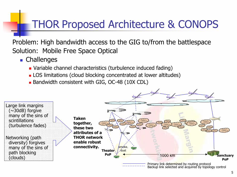
Problem: High bandwidth access to the GIG to/from the battlespaceSolution: Mobile Free Space Optical
Challenges Variable channel characteristics (turbulence induced fading) LOS limitations (cloud blocking concentrated at lower altitudes) Bandwidth consistent with GIG, OC-48 (10X CDL)
Large link margins (~30dB) forgive many of the sins of scintillations (turbulence fades)
Networking (path diversity) forgives many of the sins of path blocking (clouds)
Taken together, these two attributes of a THOR network enable robust connectivity.
6
Scintillation & Clouds
Altit
ude
(km
)
0 2 4 6 8 10 12 14 16 18 200
2
4
6
8
10
12
14
16
18
20CumulonimbusStratusStratocumulusCumulusAltostratusNimbostratusAltocumulusCirrostratusCirrocumulusCirrus
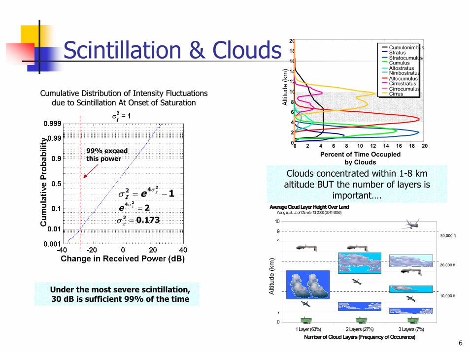
Percent of Time Occupied by Clouds
Clouds concentrated within 1-8 km altitude BUT the number of layers is
important….
99% exceed this power
1242 −= χσσ eI
224 =χσe
173.02 =χσ
Cumulative Distribution of Intensity Fluctuations Cumulative Distribution of Intensity Fluctuations due to Scintillation At Onset of Saturationdue to Scintillation At Onset of Saturation
10,000 ft
20,000 ft
30,000 ft
Average Cloud Layer Height Over LandWang et al., J. of Climate 13 2000 (3041-3056)
0
1
2
3
4
5
6
7
8
9
10
1 Layer (63%) 2 Layers (27%) 3 Layers (7%)Number of Cloud Layers (Frequency of Occurence)
Clo
ud H
eigh
t (km
)Al
titud
e (k
m)
Under the most severe scintillation, 30 dB is sufficient 99% of the time

7
Network Availability versusNumber of Links
75% Chance of a link being down due to clouds
0
0.2
0.4
0.6
0.8
1
1 2 3 4 5 6
Number of Tactial UAVs
Ava
ilabi
lity
3 links /aircraft
4 links /aircraft5 links /aircraft
6 links /aircraftIncreasing # of Planes
Increasing # of Links
Tactical to Mid Link availability = .25
Tactical to Ground Link availability = .95
Crosslinkavailability = .95
Vary # nodes, # links per node (shown: 3 nodes, 4 links/node)
3 links per node introduces redundancy4 links per node increases redundancy
Scene model
8
FSO General Availability
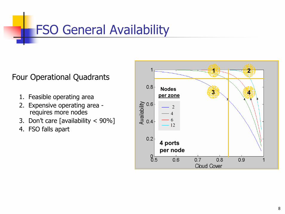
24612
Nodes per zone
4 ports per node
2 4 6 8
1 2
3 4
Four Operational Quadrants
1. Feasible operating area2. Expensive operating area -
requires more nodes3. Don’t care [availability < 90%]4. FSO falls apart

9
Power of Path Diversity
Not to Scalesmoke,
dust
Primary link determined by routing protocol Backup link selected and acquired by topology control
SanctuaryPoP
TheaterPoP 1000 km
Path Diversity Needed to Route Around BlockagesConcentrate Nodes at Lower Altitudes (< 8 km)Multiple Ports per Node to Achieve Route Diversity
Yields high network availability (under all but extreme cloud cover)Reduces number of nodes (aircraft) needed
200 km links
1
2
3
4 56
7
8
9
10
A Cumulative Solution
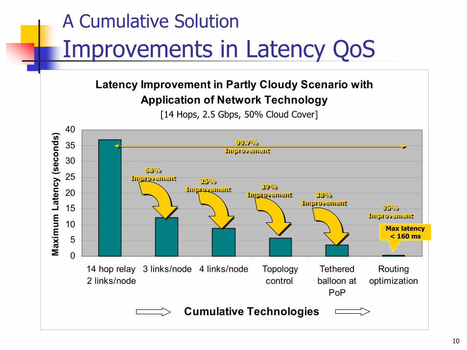
Improvements in Latency QoSLatency Improvement in Partly Cloudy Scenario with
Application of Network Technology
0
5
10
15
20
25
30
35
40
14 hop relay2 links/node
3 links/node 4 links/node Topologycontrol
Tetheredballoon at
PoP
Routingoptimization
Cumulative Technologies
Max
imum
Lat
ency
(sec
onds
)
Max latency < 160 ms
68%Improvement
68%68%ImprovementImprovement
25%Improvement
25%25%ImprovementImprovement 39%
Improvement39%
Improvement 38%Improvement
38%Improvement
95%Improvement
95%95%ImprovementImprovement
99.7%Improvement
99.7%99.7%ImprovementImprovement
[14 Hops, 2.5 Gbps, 50% Cloud Cover]

11
Networking to Route Around BlockagesRouting Diversity enables sustained data rate under cloudy conditions [14 hop scenario]
80% Cloudy 50% CloudyThe vertical red lines are the times that the link failed and required rerouting.

12
End-to-End NetworkingResults Summary
TCP Segment Delay
TCP Delay (95%)
Max TCP Delay
0% 50% 80%
Aerostat14 hops
Aerostat9 hops
No Aerostat10 hops
Cloud CoverN
etw
ork
Conf
igur
atio
n N/A
N/A
N/A
4.3 ms
0.11 sec
0.16 sec
4.3 ms
0.69 sec
0.81 sec
N/A
N/A
N/A
4.1 ms
0.1 sec
0.13 sec
8 ms
0.8 sec
1.05 sec
4.3 ms
0.098 sec
0.108 sec
6.6 ms
0.14 sec
0.23 sec
6.3 ms
0.83 sec
1.31 sec
13
THOR Phase 1Architecture Summary
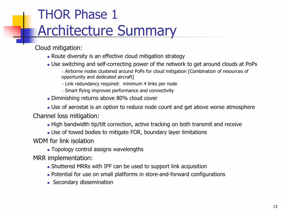
Cloud mitigation: Route diversity is an effective cloud mitigation strategyUse switching and self-correcting power of the network to get around clouds at PoPs
Airborne nodes clustered around PoPs for cloud mitigation [Combination of resources of opportunity and dedicated aircraft]
Link redundancy required: minimum 4 links per node Smart flying improves performance and connectivity
Diminishing returns above 80% cloud cover
Use of aerostat is an option to reduce node count and get above worse atmosphere
Channel loss mitigation:High bandwidth tip/tilt correction, active tracking on both transmit and receiveUse of towed bodies to mitigate FOR, boundary layer limitations
WDM for link isolationTopology control assigns wavelengths
MRR implementation:Shuttered MRRs with IFF can be used to support link acquisitionPotential for use on small platforms in store-and-forward configurations Secondary dissemination

14
THOR Phase 1Terminal Summary
Terminal:Large link margins able to compensate for scintillations Develop multiple access receiver technology to reduce size and weight by sharing
receive optical hardwareTechnologies to reduce SWaP
Develop non-mechanical beam steering to same or higher performance levels as mechanical
Increase efficiency and reduce SWaP of support equipment for high-power lasers
Increase STAB aperture so it can be used both on transmit and receiveMature volume hologram beam steering technology
Develop solutions for tracking with holographic beam steererDevelop solutions for bit rate limitations of hologramsLeverage/mitigate chromatic dispersion to support WDMIncrease aperture size supported
Develop transmissive LC SLM technology with performance of reflective to reduce size
Increasing FOR of non-gimbal beam steeringDevelop MRR technology
Higher data rates, larger aperture size, cat’s eye

15
THOR Phase 1Networking Summary
Network:Physical layer
RF links as back-up Forward error correction coding‘Long’ interleaver
Link layer Link layer retransmission as appropriateRate adaptation and RF links as backup
Network layer Smart routing to quickly respond to cloud-induced outagesQoS-based service provisioning
Transport layer Alternatives to TCP (e.g., SCPS-TP, SCTP, XCP) that are more tolerant to
RTT variance and appropriately respond to packet loss
Topology control / Resource management: Further development is requiredDiscover potential neighborsCoordinate link acquisition to maintain optimal network connectivityControls pointing, wavelength assignment
smoke,
dust
GIG
FSOCFSOC
IP
PPP PPP
MFSOC-DVQoS
Topology Control
OC192FSOC
IP
SONET PPP
MFSOC-DVOSPF
BGP
TP
QoS
TCP
Topology Control
16
Where We’re Going…
ORCLEHigh Data Rate with High Availability for Communications On The Move
17
DIRO Direction
Netw
orking
Link Marginsmoke,
dust
Primary link determined by routing protocol Backup link selected and acquired by topology control
SanctuaryPoP
TheaterPoP 1000 km
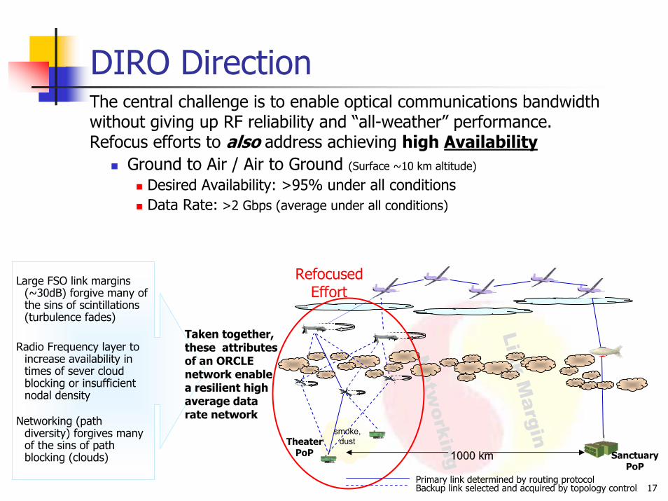
Large FSO link margins (~30dB) forgive many of the sins of scintillations (turbulence fades)
Radio Frequency layer to increase availability in times of sever cloud blocking or insufficient nodal density
Networking (path diversity) forgives many of the sins of path blocking (clouds)
Taken together, these attributes of an ORCLE network enable a resilient high average data rate network
The central challenge is to enable optical communications bandwidth without giving up RF reliability and “all-weather” performance.Refocus efforts to also address achieving high Availability
Ground to Air / Air to Ground (Surface ~10 km altitude)
Desired Availability: >95% under all conditionsData Rate: >2 Gbps (average under all conditions)
RefocusedEffort

18
ORCLE
Netw
orking
Link Margin
smoke, dust
Primary link determined by routing protocol Backup link selected and acquired by topology control
SanctuaryPoP
TheaterPoP 1000 km
ChallengesLowest 10 km of atmosphere
LOS limitations (cloud blocking concentrated at lower altitudes) Variable channel characteristics (turbulence induced fading)
High Availability in all weather conditionsFSO performance strongly tied to channel characteristicRF relative immune to most channel characteristics
High average data rate FSO high but unreliable data rateRF low data rate but reliable
Focus ofExperiment
The central challenge is to enable optical communications bandwidth without giving up RF reliability and “all-weather” performance.
Altit
ude
(km
)
0 2 4 6 8 10 12 14 16 18 200
2
4
6
8
10
12
14
16
18
20CumulonimbusStratusStratocumulusCumulusAltostratusNimbostratusAltocumulusCirrostratusCirrocumulusCirrus
Percent of Time Occupied by Clouds
Even short opportunities to “burst” very high FSO data rates leads to much higher average data rates compared to RF
19
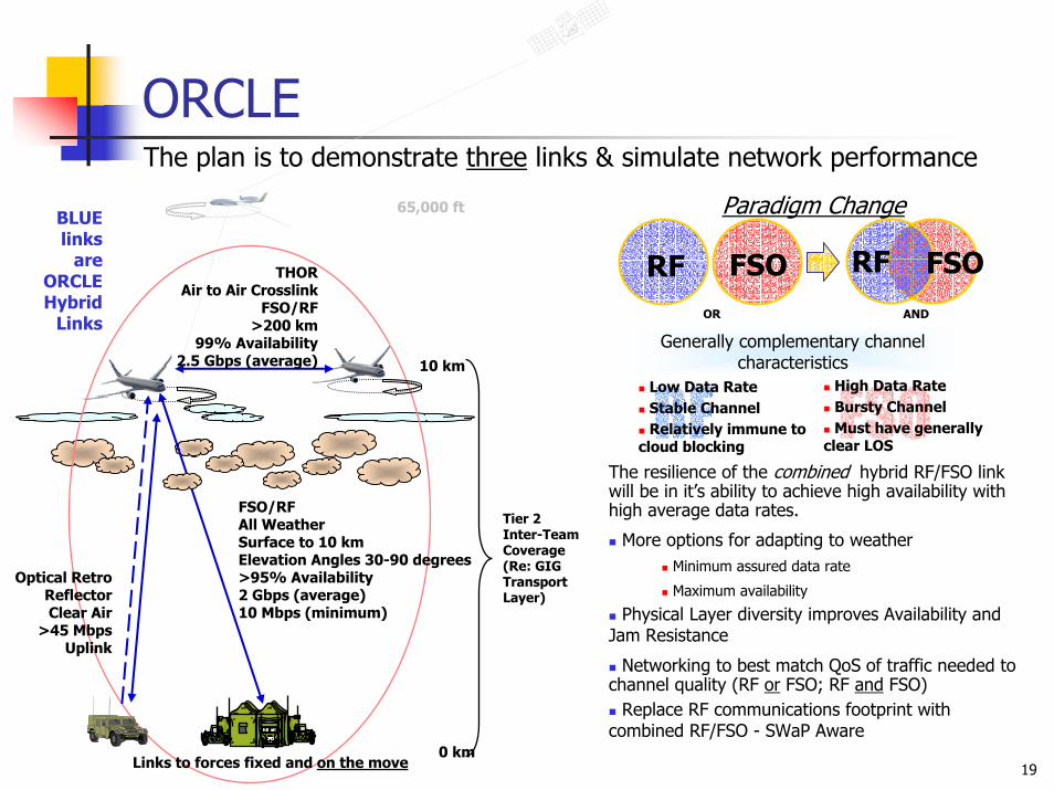
RF
ORCLE
Optical RetroReflectorClear Air
>45 MbpsUplink
FSO/RFAll WeatherSurface to 10 kmElevation Angles 30-90 degrees>95% Availability2 Gbps (average) 10 Mbps (minimum)
Links to forces fixed and on the move
10 km
0 km
Tier 2Inter-TeamCoverage(Re: GIG Transport Layer)
BLUE links
are ORCLE Hybrid
Links
THORAir to Air Crosslink
FSO/RF>200 km
99% Availability2.5 Gbps (average)
The plan is to demonstrate three links & simulate network performance
Paradigm Change
FSORF RF FSO
Generally complementary channel Generally complementary channel characteristicscharacteristics
Low Data RateStable ChannelRelatively immune to
cloud blocking
The resilience of the combined hybrid RF/FSO link will be in it’s ability to achieve high availability with high average data rates.
More options for adapting to weatherMinimum assured data rate
Maximum availability
Physical Layer diversity improves Availability and Jam Resistance
Networking to best match QoS of traffic needed to channel quality (RF or FSO; RF and FSO)
Replace RF communications footprint with combined RF/FSO - SWaP Aware
FSOHigh Data RateBursty ChannelMust have generally
clear LOS
65,000 ft
OR AND
20
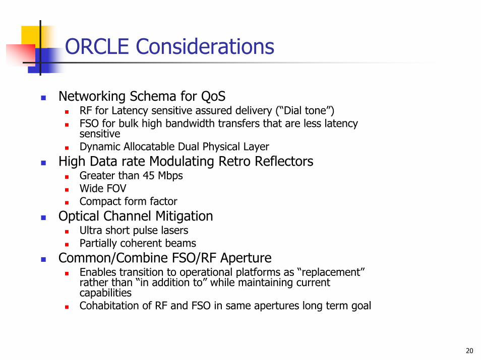
ORCLE Considerations
Networking Schema for QoSRF for Latency sensitive assured delivery (“Dial tone”)FSO for bulk high bandwidth transfers that are less latency sensitiveDynamic Allocatable Dual Physical Layer
High Data rate Modulating Retro ReflectorsGreater than 45 MbpsWide FOVCompact form factor
Optical Channel MitigationUltra short pulse lasersPartially coherent beams
Common/Combine FSO/RF Aperture Enables transition to operational platforms as “replacement” rather than “in addition to” while maintaining current capabilitiesCohabitation of RF and FSO in same apertures long term goal

21
Hybrid LinkFSO + RF Considerations
Control PlaneNetwork control plane uses RF and optical channels to leverage the complementary powers of each domain
RF channel for neighbor discovery & acquisitionSharing of GPS and INS data on aircraft position, velocity, and time
Optical channel for link quality probeUses a separate low rate optical tracking channel or data channel itselfCan also be used for operational control and signaling
The control plane integrates information from each domain, utilizing both to optimize network performance
Topology optimization and dissemination, physical provisioning, identification of back-up paths all flow from the control plane information
The control plane media is RF for out-of-band, inter-node control
Data Plane Traffic Management
Control plane enables multiple data level priorities through intelligent allocation of bandwidthHardware must be consistent with traffic management rules
e.g. Interfaces, RF/optical switching, RF/optical redundancy
System requirements for high priority dataMax data rate determined by RF networkLatency must be minimized
The RF channel can reliably carry control traffic that enables adaptation at multiple levels
Application Transport HostRF
Optical
Application can change its traffic mode based on Predictive DiffServ
TCP can adjust retransmission timers and congestion parameters based on Explicit Congestion control and Explicit Transport Error Notification
DiffServ Code points can be used to pick routing table, queue or change link processing
ARQ on links can make optical links more reliable(at the cost of more delay)
Routing can have multiple tables to allow for paths with Different QoS
• Beam Alignment • Link ACKS• Routing Updates (generally not desired)• TCP ACKs• Explicit Congestion Indicators• Explicit Loss Indicators•Topology Control Information
ORCLE Hybrid Links

22
ORCLE Acquisition Strategy
Contract Awards (up to 2) to System Integrators for Range Demonstration (~month 16-18) and Flight Demonstration (~month 28-30) of prototype system. Focus of the demonstrations will be to prove concepts for:
Hybrid NetworkingHigh Data Rate Modulating Retro Reflector
Contract Awards (multiple) for innovative high risk and high payoff development and testing of concepts for:
Common/Combine FSO/RF ApertureOptical Channel Mitigation Hybrid Routing TechnologyCompact Optical Beam Steering
The PRIMARY focus of ORCLE
The technologies that will facilitate and enable ORCLE to transition to the warfighter
23
Notional
Evaluation Criteria
Technical ApproachOperational UtilityConcept of OperationsManagement ApproachPotential Contribution and Relevance to DARPA MissionCost Realism
24
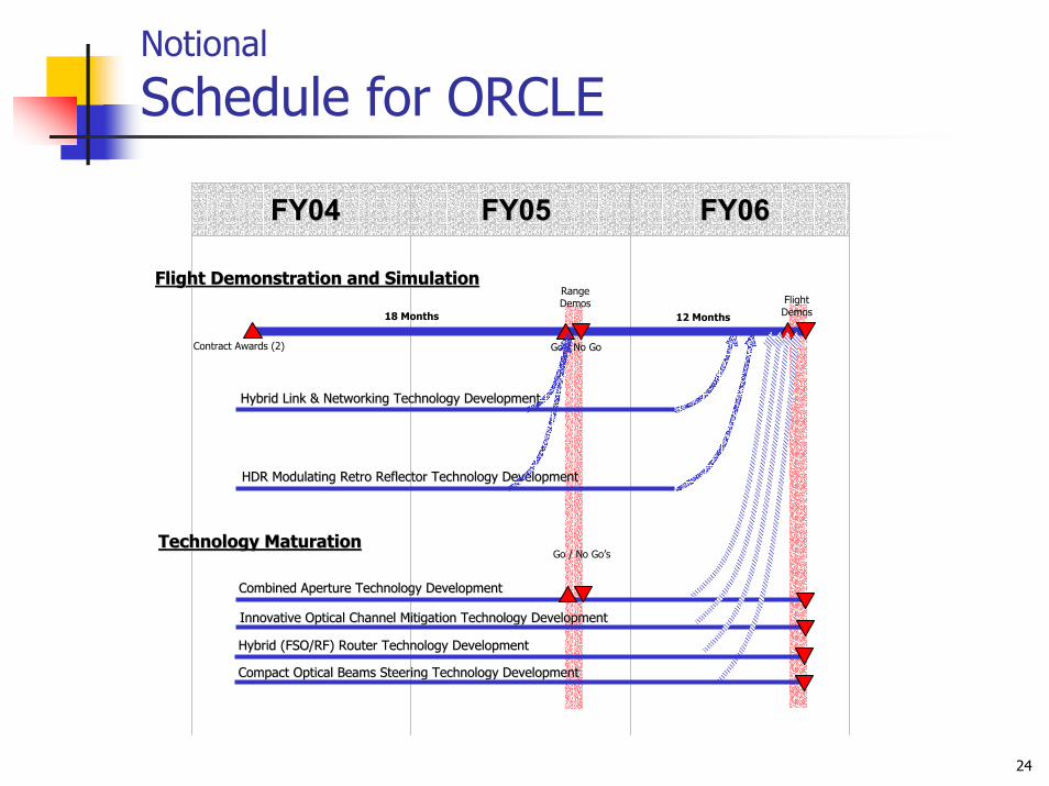
Notional
Schedule for ORCLE
FY04FY04 FY05FY05 FY06FY06
Contract Awards (2)
FlightDemos
Go / No Go
Innovative Optical Channel Mitigation Technology DevelopmentInnovative Optical Channel Mitigation Technology Development
Combined Aperture Technology DevelopmentCombined Aperture Technology Development
Hybrid Link & Networking Technology DevelopmentHybrid Link & Networking Technology Development
HDR Modulating Retro Reflector Technology DevelopmentHDR Modulating Retro Reflector Technology Development
RangeDemos
Technology MaturationTechnology Maturation
Hybrid (FSO/RF) Router Technology DevelopmentHybrid (FSO/RF) Router Technology Development
Compact Optical Beams Steering Technology DevelopmentCompact Optical Beams Steering Technology Development
18 Months
Go / No Go’s
Flight Demonstration and SimulationFlight Demonstration and Simulation
12 Months

25
Go / No Go Criteria and Conditions
40 hours of flight testing per a/c (80 hrs total).
Test Hybrid Link under a variety of environmental conditions (clear to cloudy).
FLIGHT DEMO – Ground to Air to Air of HYBRID FSO/RF Link
G-A-A Availability >95%Demonstrate >2.0 Gbps average data rateDemonstrate Common / Combined FSO&RF Aperture
FLIGHT DEMO – Mobile Ground to AirMRR data rate >45 Mbps at 20 kmModel performance for conditions in South East Asia
during July for a 20 node hybrid network over a 1000 km area with 2 ground nodes (one fixed and one mobile)
Flight Demo[Gov’tRange]
30
Place terminals on motion tables to simulate C135 flight vibration environment and aircraft motion.
Vary the optical opacity over time using screens (A-A and A-G tests)
40 hours simulated A-A test time
40 hours simulated A-G test time
RANGE DEMO of HYBRID FSO/RF LinkMountain Top to Mountain Top as surrogate Air to Air
(~50 km separation)Mountain Top to Ground as surrogate Air to Ground Link
(~12 km separation)G-A, A-A Availability >95%Demonstrate >2.0 Gbps average data rate
MRR data rate >45 Mbps at 12 kmModel performance for conditions in South East Asia
during July for a 10 node hybrid network over a 400 km area with 2 ground nodes (one fixed and one mobile)
Range Demo[White Sands Missile range]
18
ConditionsGo /No Go CriteriaEvent
Months After
Contract Award

Briefing Complete


