37
Proposed Code of Practice for BIM e-Submission Part 3: MEP Requirements Draft version date: 29/9/2015

Proposed Code of Practice for BIM e-Submission Part 3: MEP Requirements
Draft version date: 29/9/2015

BCA acknowledges the leadership provided by the BIM Steering Committee in support of the production of the Proposed Technical Reference for BIM e-submission.
The Proposed Technical Reference for BIM e-submission has been drafted by the Centre for Construction IT on behalf of BCA and the BIM Steering Committee. ©Building and Construction Authority 2015 Building and Construction Authority 52 Jurong Gateway Road, #11-01 Singapore 608550 (Above JEM) www.bca.gov.sg First published October 2015 While every effort has been made to ensure the accuracy and quality of information contained in this publication, the Building and Construction Authority, its employees, agents or industry partners can take no responsibility for the subsequent use of this information, nor for any errors or omissions that it may contain.
Cover image and design courtesy of RSP
Architects Planners & Engineers (Pte) Ltd,
Squire Mech and the BCA Academy of the
Built Environment.

Proposed Code of Practice for BIM e-Submission – Part 3. MEP Requirements
i
ACKNOWLEDGEMENTS
The development of this technical requirement has been a collaborative effort among a cadre of very knowledgeable consultants and processing officers from different regulatory agencies. Significant contributors are listed below: Regulatory agencies: Public Utility Board Water Supply Network Department
Infocomm Development Authority Telecommunication Facility Coordination Committee
CityGas Pte Ltd Parks & Tree Regulatory Section Participating Consultants: AECOM Pte Ltd Arup Pte Ltd PTA Consultants Pte Ltd Surbana International Consultants Pte Ltd Squire Mech Pte Ltd United Project Consultants Pte Ltd

OBJECTIVES
The objective of this Document is to assist qualified persons (QPs) in developing BIM models to meet new requirements of Building Information Model (BIM) submission. It describes the requirements and guidance for creating BIM with specific object types, associated properties and presentation format to the following regulatory agencies for processing:
a. Public Utility Board (PUB), Water Supply Network Department b. Infocomm Development Authority (IDA) c. CityGas Pte Ltd
This submission guideline contains a list of requirements written in a concise form to guide QPs in e submission to the above mentioned regulatory agencies. It is by no means an exhaustive
SCOPE These submission guidelines contain lists of requirements of the building works which must be complied with when making a building plan or planning submission. The items in this Standard Guideline may also be amended or revoked when new written laws come into force. For more information or enquiries on the specific submission requirements, please consult the appropriate regulatory agency above. For Software specific on how to BIM e-submission, refer to Appendix A of this guide. These user manuals should be read carefully as this Document cannot take into account all the special features of individual BIM application. For any submission requirements mentioned in the Appendices that require customisations to a certain extent, QPs are also advised to make reference to the training materials distributed or to consult the respective software vendor for any enquiries on the application. If there are contradictions between this submission guideline and vendor’s instructions, BCA BIM team shall be contacted for clarification.
Note: The respective regulatory agency reserves the right to reject and request for necessary correction of any required deliverables or formats that do not meet the requirements.

Proposed Code of Practice for BIM e-Submission – Part 3: MEP Requirements
Copyright © 2015 Building and Construction Authority. All Rights Reserved. Page 3
Table of Contents
ACKNOWLEDGEMENTS ________________________________________________________ i
OBJECTIVES __________________________________________________________________ 2
I. GENERAL REQUIREMENTS ________________________________________________ 5
1. Deliverables __________________________________________________ 5
1.1 File Format & Software Version ______________________________ 5
1.2 File and Folder Structure ___________________________________ 5
File Structure ___________________________________________________ 5
1. Model Orientation and Site Configuration _________________________________________ 6
2. Scale ____________________________________________________________________________________ 6
3. Standard Naming Convention of Files and Views ________________________________ 6
3.1 File Naming _____________________________________________ 6
3.2 View Naming ____________________________________________ 7
4. Core Information (CI) for BIM Objects ______________________________________________ 8
5. Annotations and Dimensions ________________________________________________________ 9
6. Last Saved Views _____________________________________________________________________ 9
7. Cover Page ____________________________________________________________________________ 9
8. Addition & Alterations and Amendment Submissions __________________________ 10
II. AGENCY- SPECIFIC REQUIREMENTS ______________________________________ 12
A. PUB-WTR SUBMISSION REQUIREMENTS ___________________________________ 12
1. General Requirements for all PUBWTR Submissions _________________ 12
1.1. 2D Views __________________________________________________ 12
1.2. Part 3D BIM Model __________________________________________ 14
B. IDA-TFCC SUBMISSION REQUIREMENTS ___________________________________ 15
1. General Requirements for Submission of BIM model to IDA _______ 15
1.1. Site Plan and Location Plan View ____________________________ 15
1.1.1. Location Plan ___________________________________________ 15
1.1.2. Site Plan _______________________________________________ 15
1.2. BIM Model & generated plans from BIM model _________________ 16
1.2.1. Part 3D Model ___________________________________________ 18
1.2.2. Main Distribution Frame or Telecommunication Equipment Room ___ 18
1.2.3. Telecommunication Risers _________________________________ 18
1.3. Schedule _______________________________________________ 18
1.4. Colour code for TFCC submission ___________________________ 19
C. CityGAS SUBMISSION REQUIREMENTS ______________________________________ 21
Proposed Code of Practice for BIM e-Submission – Part 3: MEP Requirements
Copyright © 2015 Building and Construction Authority. All Rights Reserved. Page 4
1. General Requirements for Submission of BIM model to City Gas ___ 21
1.1. Plans Submission ________________________________________ 21
1.1.1. Location plan ___________________________________________ 21
1.1.2. Site Plan _______________________________________________ 22
1.1.3. Plans generated from BIM model and Part 3D BIM Model _________ 23
1.1.4. Schematic Diagram and Detail plan __________________________ 24
1.2. Colour code for gas piping _________________________________ 25
1.3. File Deliverable Requirements ______________________________ 25
1.4. Pipe materials and sizes used for gas installation _______________ 25
Appendix A. Step by step BIM Template guide __________________________________ 27
A.1 Autodesk Revit ______________________________________________________________________ 27
A.2 Bentley AECOSIM __________________________________________________________________ 27
A.3 Graphisoft ARCHICAD _____________________________________________________________ 27
Appendix B. Standard Certification for Building Works __________________________ 42
Table Formats ________________________________________________________________ 47
Figures ______________________________________________________________________ 48
Proposed Code of Practice for BIM e-Submission – Part 3: MEP Requirements
Copyright © 2015 Building and Construction Authority. All Rights Reserved. Page 5
I. GENERAL REQUIREMENTS
1. Deliverables
1.1 File Format & Software Version
All submissions shall be in Native file format (ie. .rvt, .dgn, .pla etc).
For the latest acceptable Native file format and software version, always refer to https://www.corenet.gov.sg/general/building-information-modeling-(bim)-e-submission.aspx Plans, elevations, sections, layout views or sheets (refer to Appendix A for specific requirements from each regulatory agency), with appropriate titleblock and PE’s stamp; a. Schematic Diagram is required for submission to all agencies
involved
b. Notes and Legend is required for submission to all agencies
involved
c. Site Plans and Location Plans is required for submission to all
agencies involved
d. Native file should include:
Complete BIM model showing the complete services
Part 3D BIM model (services + archi model, if any) by floor/ by
shafts/ important part cross sections (Refer to Appendix A)
Take note of the naming convention – if part section, include grid
numbers (Refer to Section 2.4)
1.2 File and Folder Structure All submissions shall be structured by the following:
File Structure
Single file
o One single BIM to contain all information. Suitable for small
sized project with only one main building.
Federated files

Proposed Code of Practice for BIM e-Submission – Part 3: MEP Requirements
Copyright © 2015 Building and Construction Authority. All Rights Reserved. Page 6
o Several BIM to contain all information. Suitable for medium to
bigger sized projects with several buildings; or that are too big to
handle.
o UNC (Universal Naming Convention) path or Relative path shall
be used.
QPs may opt to use any of the above mentioned method, whichever is appropriate for the project.
1. MODEL ORIENTATION AND SITE CONFIGURATION
The site, building model or its adjacent buildings should be drawn in the real orientation or spatial coordinate system and with reference to Singapore Standard Datum (>100M), rather than project reference level at zero ground.
2. SCALE
All BIM submitted for approval has to be drawn in real size as built (1:1) in metric scale.
3. STANDARD NAMING CONVENTION OF FILES AND VIEWS
Standard naming convention shall be used.
3.1 File Naming Project ID Author Block/
Zone Unit/
Storey Submission
Version Software
Version User- defined
Single File example:
Project ID Author Block/ Zone
Unit/ Storey
Submission
Version Software Version User- defined
M L P 1 _ A - _ M A I N _ - - _ A _ 1 3 _
Federated Files example:
Project ID Author Block/ Zone
Unit/ Storey
Submission
Version Software Version User- defined
M L P 1 _ A - _ M A I N _ - - _ A _ 1 3 _ S I T E
M L P 1 _ A - _ 1 0 1 _ - - _ A _ 1 3 _ B L K 1 0 1
M L P 1 _ A - _ - - _ A 1 _ A _ 1 3 _ U N I T A 1
Registered Land Surveyor shall provide X, Y, Z points.
All 2D Views generated from BIM shall not have odd drawing scales.
Ex
A relative path defines the position of a linked file in a working directory such as project folder. Its position is defined by its relative location.

Proposed Code of Practice for BIM e-Submission – Part 3: MEP Requirements
Copyright © 2015 Building and Construction Authority. All Rights Reserved. Page 7
Table 1. File Naming convention Name of field Indicators Max. number
of characters Description
Project Identification 4 User defined field for the project
Author A- 1 Architect
C- Civil engineer
G- Geotechnical engineer
E- Electrical engineer
L- Land surveyor
M- Mechanical engineer
N- Equipment supplier
S- Structural engineer
T- Telecommunication/ signal engineer
V- Other disciplines
X- Contractor
Zone/ Block NN 4 where, N=Zone or Block number Eg.: 101 for Block 101 A1 for Zone A1 POD for Podium
-- For all blocks
Unit or Storey/ Level
NN
3 where, N= Unit or Storey/ Level Eg.: A2 for Unit A2
--- For all Unit or Storey/ Level
Software Version NN 2 where, N= software version Eg.: 13 for Revit 2013 S5 for Aecosim ss5 18 for Archicad 18
User- defined NN 4 User- defined code for in- house applications
3.2 View Naming
Agency Type of View View Name
F S S D - _ F P _ 1ST S T O R E Y
Table 2 View Naming Convention Name of field Indicators Max. number
of characters Description
Agency CBPD 6 Central Building Plan Department
WRN Water Reclamation (Network)
WTR Water Supply Network
FSSD Fire Safety and Shelter Department
TFCC Telecommunication Facility Coordination Committee
CITYGAS CityGas Pte Ltd
Type of view SP 2 Site Plan
FP Floor Plan
FE Elevation

Proposed Code of Practice for BIM e-Submission – Part 3: MEP Requirements
Copyright © 2015 Building and Construction Authority. All Rights Reserved. Page 8
FX Section
DT Detail
3D 3D
LV Layout View (Cover Page)
DG Schematic Diagram
LG Legend
DP Diagrammatic Plan( for strata boundaries)
LP Landscape Plan
AP Area Plan
TP Terrain/ Topographic Plan
View Name (user- defined)
01 3 01 Storey/ Level 02 Storey/ Level where, N= Storey’s no. 01M- 99M 01B- 99B
02
NN
Mezzanine M
Basement N
Elevation N where, N = Directions Eg. East, West, North, South; or 1, 2, 3, 4
Section N where, N = Section’s number
Summary of X where, X = Schedule’s name e.g. GFA
4. CORE INFORMATION (CI) FOR BIM OBJECTS
All submissions shall have minimal Core Information (CI) as specified by the respective regulatory agency. Refer to III. Core Information (CI) for BIM Objects
Table 3. Terms used in Core Information (CI)
Building
Element
Refers to the actual physical element constructed on site by
the contractors.
BIM Object Refers to the BIM object to be used to create the building
element in the model.
Parameters Refer to the attributes/ parameters required by individual
regulatory agencies.
Name: Name of the parameter
Data List: Valid list of values for each parameter
Remarks: Any other specific remark in particular to the
parameter.

Proposed Code of Practice for BIM e-Submission – Part 3: MEP Requirements
Copyright © 2015 Building and Construction Authority. All Rights Reserved. Page 9
5. ANNOTATIONS AND DIMENSIONS
All submissions shall have minimal annotations as specified by the respective regulatory agency. Refer to Agency- Specific Requirements.
6. LAST SAVED VIEWS
Checking and approval from the regulatory agencies is based on the “Last Saved Model”, together with the “Last Saved View” of site plans, floor plans, elevations and sections submitted. Therefore, QPs are to ensure that the following items are checked upon submission: a. Maximum extent is saved for each view; b. No hidden objects or annotations; c. Any link (3D model or BIM saved in other file) that is considered part of the submission is loaded upon submission; d. There shall be no missing/ unreadable external files. e. All other external references, irrelevant drawing layers, objects, annotations, draft work and construction lines, which are not part of the proposed building elements, are to be removed or purged upon submission; and f. No propriety fonts are used for annotations and all the fonts should be legible; and g. All objects and annotation in each phase were displayed in the last saved view.
7. COVER PAGE
Use the provided Title Block in the Template. Red box indicates the portion that can be changed. Customise the information according to company requirements.
Cover Page shall have the following information:
Project Information
View List/ Schedule List
Endorsement/ QPs declaration
Figure 1. Cover Page
<To customise this
portion>
<To customise this portion>

Proposed Code of Practice for BIM e-Submission – Part 3: MEP Requirements
Copyright © 2015 Building and Construction Authority. All Rights Reserved. Page 10
8. ADDITION & ALTERATIONS AND AMENDMENT SUBMISSIONS
The same BIM model (with changes incorporated to comply with the
requirements) should be used in resubmission (i.e. no shifting of spatial
coordinate system in the re-submitted model). The revised submission should be
indicated clearly in the name of BIM file submitted.
For any plan of alteration or addition to an existing building, or, re-submission for
regulatory approval, all the building objects or elements should be demarcated
clearly by colours in Table 4 (in accordance with SS CP83 Part 5):
Table 1 Colours used for A&A project
Colour Usage
Magenta Proposed elements
Cyan Existing elements
Yellow Deleted elements
Any building works which are to be deleted, removed or demolished must be
shown in dotted lines on the plans and presented in a manner that can be
easily identified or distinguished, as shown in Figure 3.
Figure 1 Sample of A&A project / project for re-submission (plan and 3D views)

Proposed Code of Practice for BIM e-Submission – Part 3: MEP Requirements
Copyright © 2015 Building and Construction Authority. All Rights Reserved. Page 11
PEs should include a complete set of all related model views (plans, elevations,
sections and 3D views) in every submission, including the re-submission of
amendments. For any model view which contains NO amendments, a box indicating
that this is “For Reference ONLY” shall be placed on the top right corner of the model
view, and all its building objects or elements shall be demarcated with CYAN colour,
as shown in Figure 4.
Figure 2 Sample of project for re-submission (plan view for storey with no amendments)
Proposed Code of Practice for BIM e-Submission – Part 3: MEP Requirements
Copyright © 2015 Building and Construction Authority. All Rights Reserved. Page 12
II. AGENCY- SPECIFIC REQUIREMENTS
A. PUB-WTR SUBMISSION REQUIREMENTS
1. General Requirements for all PUBWTR Submissions
Only Schematic Line Diagram and 3D cross sectional model of important
parts/zones, as specified below, are required for PUBWTR BIM e-submission.
No 2D floor plans, elevations and sectional drawing views are required during
submission
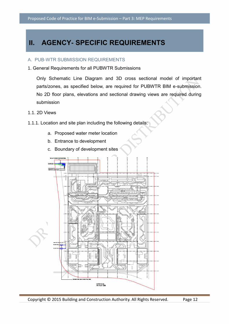
1.1. 2D Views
1.1.1. Location and site plan including the following details:
a. Proposed water meter location
b. Entrance to development
c. Boundary of development sites

Proposed Code of Practice for BIM e-Submission – Part 3: MEP Requirements
Copyright © 2015 Building and Construction Authority. All Rights Reserved. Page 13
1.1.2. Overall water system schematic drawing shall indicate the following:
a. Proper labeling to be provided for the various water pipes
b. The following color code shall be adopted:
i. Direct water supply from PUB water main in BLUE
ii. Indirect water supply via gravity feed in GREEN
iii. Indirect water supply via pump feed in BROWN
iv. Hot water supply/return pipes in BLACK
v. NEWater in PURPLE
c. Reduced level of platform
d. Reduced level of highest water fitting/fire hydrant (if applicable)
receiving direct supply from PUB water mains
e. Diameter of all water pipes
f. Terminal water draw-off fittings
g. Breakdown of estimated daily and indirect water requirements
h. Water tank including the following details:
i. Inlet, outlet, overflow, warning and drain pipes with their
diameters indicated
ii. Reduced level of inlet to tank
iii. Material of tank
iv. Nominal size and effective capacity of tank to be indicated
Proposed Code of Practice for BIM e-Submission – Part 3: MEP Requirements
Copyright © 2015 Building and Construction Authority. All Rights Reserved. Page 14
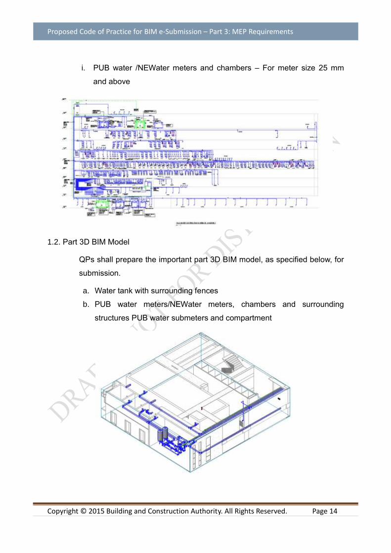
i. PUB water /NEWater meters and chambers – For meter size 25 mm
and above
1.2. Part 3D BIM Model
QPs shall prepare the important part 3D BIM model, as specified below, for
submission.
a. Water tank with surrounding fences
b. PUB water meters/NEWater meters, chambers and surrounding
structures PUB water submeters and compartment

Proposed Code of Practice for BIM e-Submission – Part 3: MEP Requirements
Copyright © 2015 Building and Construction Authority. All Rights Reserved. Page 15
B. IDA-TFCC SUBMISSION REQUIREMENTS
1. General Requirements for Submission of BIM model to IDA
The models to be submitted shall meet the requirements specified under chapter 3 of
the Code of Practice for Info-communication Facilities in Buildings (COPIF). The
plans shall contain but not limited to the sectional and elevation drawings of the
building. All dimensions and grids shall be indicated clearly on the plans.
When submitting the plans, avoid odd scales. The scales and grid reference shall
also be indicated on all plans.
1.1. Site Plan and Location Plan View
The plans shall contain details of the following:
1.1.1. Location Plan
a. The location of the lot relative to its neighboring lots; and
b. The various roads constituting the access layout to the lot
Example:
1.1.2. Site Plan
a. The means of access to the site and to the perimeter of each building;
b. Distances between buildings and/or structures

Proposed Code of Practice for BIM e-Submission – Part 3: MEP Requirements
Copyright © 2015 Building and Construction Authority. All Rights Reserved. Page 16
c. The existing (if any) and proposed underground telecommunication systems at
the site
d. The North/East Coordinates (e.g. E12345.678/N12345.678) and
e. Temporary Occupancy Date
1.2. BIM Model & generated plans from BIM model
Models/Plans to be submitted for lead-in pipes, main distribution frame (MDF) room,
and telecommunication equipment room (TER), telecommunication risers and
residential units or tenant premises shall include the following:
a. Dimensions and the location of the lead-in pipes including the depth which the
lead-in pipes is to be located;
b. Dimensions of the MDF and TER rooms (i.e. length, breadth and height) ;
c. Dimensions of the telecommunication riser (i.e. width and depth) and the
location, size of the metal cable trays to be provided on the depth sides of the
telecommunication risers; and

Proposed Code of Practice for BIM e-Submission – Part 3: MEP Requirements
Copyright © 2015 Building and Construction Authority. All Rights Reserved. Page 17
d. The layout plan and model for every floor highlighting the location and height of
respective telecommunication points, i.e. TV points, telephone points, data
points, fibre termination points, etc.
e. Colour codes all the telecommunication risers.
Example:
Plan view
Part 3D model
Proposed Code of Practice for BIM e-Submission – Part 3: MEP Requirements
Copyright © 2015 Building and Construction Authority. All Rights Reserved. Page 18
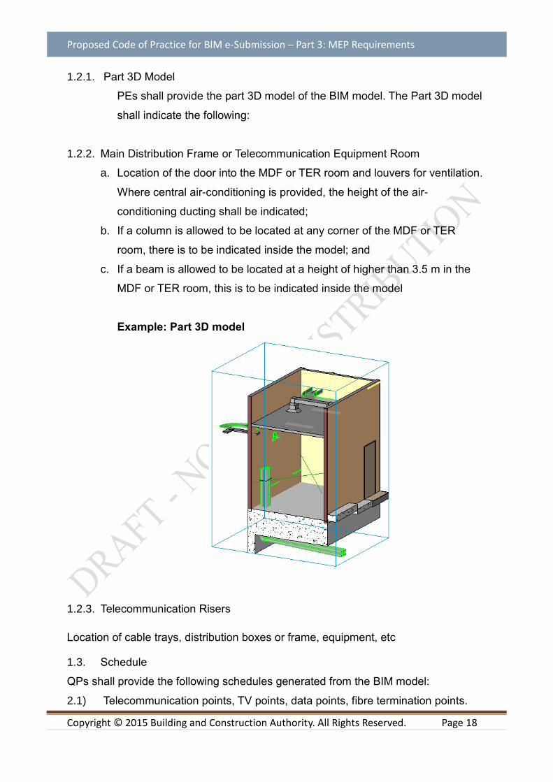
1.2.1. Part 3D Model
PEs shall provide the part 3D model of the BIM model. The Part 3D model
shall indicate the following:
1.2.2. Main Distribution Frame or Telecommunication Equipment Room
a. Location of the door into the MDF or TER room and louvers for ventilation.
Where central air-conditioning is provided, the height of the air-
conditioning ducting shall be indicated;
b. If a column is allowed to be located at any corner of the MDF or TER
room, there is to be indicated inside the model; and
c. If a beam is allowed to be located at a height of higher than 3.5 m in the
MDF or TER room, this is to be indicated inside the model
Example: Part 3D model
1.2.3. Telecommunication Risers
Location of cable trays, distribution boxes or frame, equipment, etc
1.3. Schedule
QPs shall provide the following schedules generated from the BIM model:
2.1) Telecommunication points, TV points, data points, fibre termination points.

Proposed Code of Practice for BIM e-Submission – Part 3: MEP Requirements
Copyright © 2015 Building and Construction Authority. All Rights Reserved. Page 19
2.2) Electrical DB points
Example:
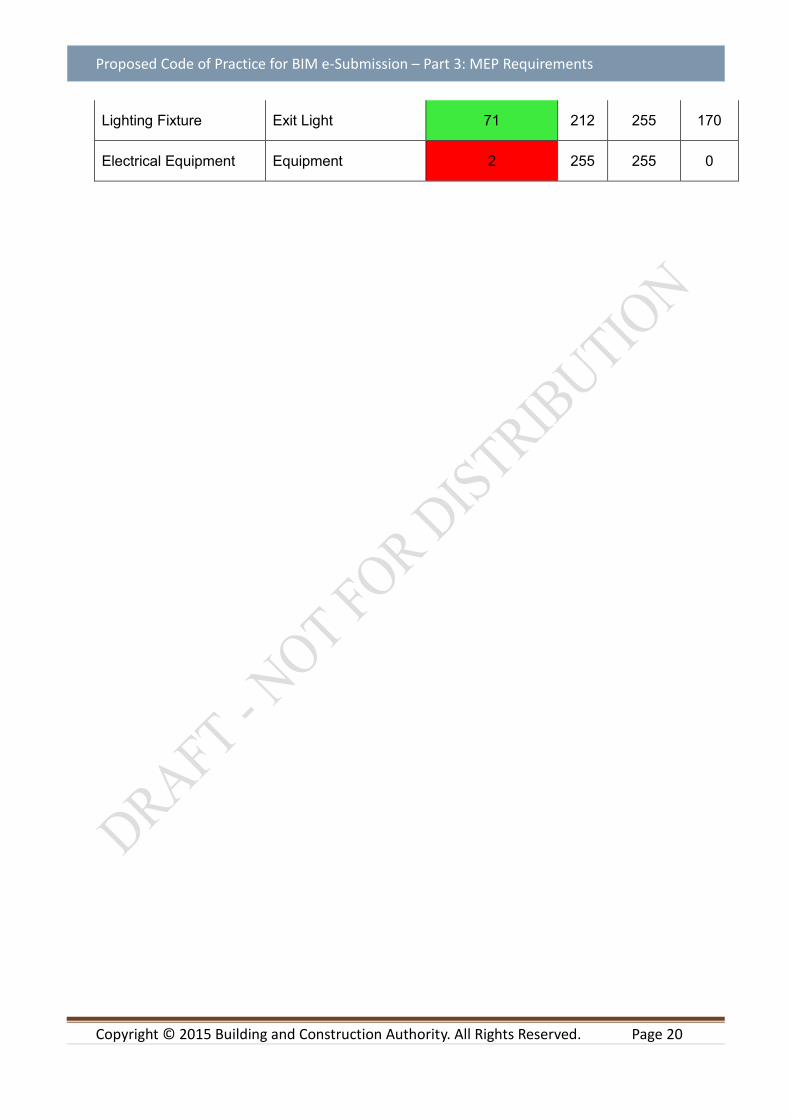
1.4. Colour code for TFCC submission
SYSTEM TYPE SYSTEM CLASSIFICATION
COLOR DECIMAL
RED2
GREEN3
BLUE4
Normal Power Cable Tray/Trunking/Ladder (Hatch)
Tray/Trunking/Ladder 131 170 255 255
Emergency Power/Gsm /Security Cable Tray/ Trunking/Ladder(Hatch)
Tray/Trunking/Ladder 80 63 255 0
Telecommunication System (Tel/Data Scv)
Tray/Trunking/Ladder 131 170 255 255
Power System S/S/O, Isolator etc 80 63 255 0
Public System Speaker 80 63 255 0
Lighting Fixture Normal 241 255 170 199
Lighting Fixture Essential/Battery 71 212 255 170
Lighting Circuit (Dashed Line Type)
Normal 51 255 255 170
Lighting Circuit (Divide Line Type)
Essential/Battery 61 234 255 170
Lighting Fixture Switch 131 170 255 255
Proposed Code of Practice for BIM e-Submission – Part 3: MEP Requirements
Copyright © 2015 Building and Construction Authority. All Rights Reserved. Page 20
Lighting Fixture Exit Light 71 212 255 170
Electrical Equipment Equipment 2 255 255 0
Proposed Code of Practice for BIM e-Submission – Part 3: MEP Requirements
Copyright © 2015 Building and Construction Authority. All Rights Reserved. Page 21
C. CITYGAS SUBMISSION REQUIREMENTS
1. General Requirements for Submission of BIM model to City Gas
This document provides the general guidelines for professional engineers and
licensed gas service workers to comply when they submit BIM model to City Gas.
The professional engineers/ licensed gas service workers shall ensure the design of
the gas installation and all gas service works carried out on the gas installation
comply with the requirements and provisions of the latest revision of the following:
a) The Gas Act (Cap 116A);
b) The Gas (Supply) Regulations;
c) The Gas Supply Code
d) Code of Practice for Gas Installation, Singapore Standard, CP51
e) City Gas Handbook on Gas Supply; and
f) Any other relevant rules, regulations and Codes of Practice
1.1. Plans Submission
Each submission plan shall bear the declaration on the right side column of the
layout sheet shown below. A blank space of 90mm (w) x 60mm (h) shall also be
provided on the right side column for City Gas internal use. Please refer to City Gas
Handbook on Gas Supply for Designated Representative’s declaration required by
City Gas.
The submission of plans for approval by Designated Representative shall consist of the following plans: 1.1.1. Location plan
a. Submission shall include a location plan with the development boundary line
highlighted in red.

Proposed Code of Practice for BIM e-Submission – Part 3: MEP Requirements
Copyright © 2015 Building and Construction Authority. All Rights Reserved. Page 22
Location Plan Example
1.1.2. Site Plan
a. Plan shall prepare at a scale of 1:500 or 1:1000
b. Highlight the development boundary line in red
c. Plan shall have grid lines and dimension indicate
d. Plan shall show the specifications of pipe installation
e. Indicate the location of gas connection

Proposed Code of Practice for BIM e-Submission – Part 3: MEP Requirements
Copyright © 2015 Building and Construction Authority. All Rights Reserved. Page 23
Example of Site Plan
1.1.3. Plans generated from BIM model and Part 3D BIM Model a. Plan shall preferably be submitted at a scale of 1:100 or 1:200
b. Plan shall have grid lines and dimension indicated
c. Indicate the location of the gas connection
d. Each compartment/space shall indicate clearly with annotations of;
The purpose of the compartment/space

Proposed Code of Practice for BIM e-Submission – Part 3: MEP Requirements
Copyright © 2015 Building and Construction Authority. All Rights Reserved. Page 24
The mode of ventilation of the compartment/space
e. Plan shall show the specifications of gas pipe and pipe sleeve
f. Roof plan shall be submitted if the gas duct ventilation is proposed at
roof level
Example of Floor Plan
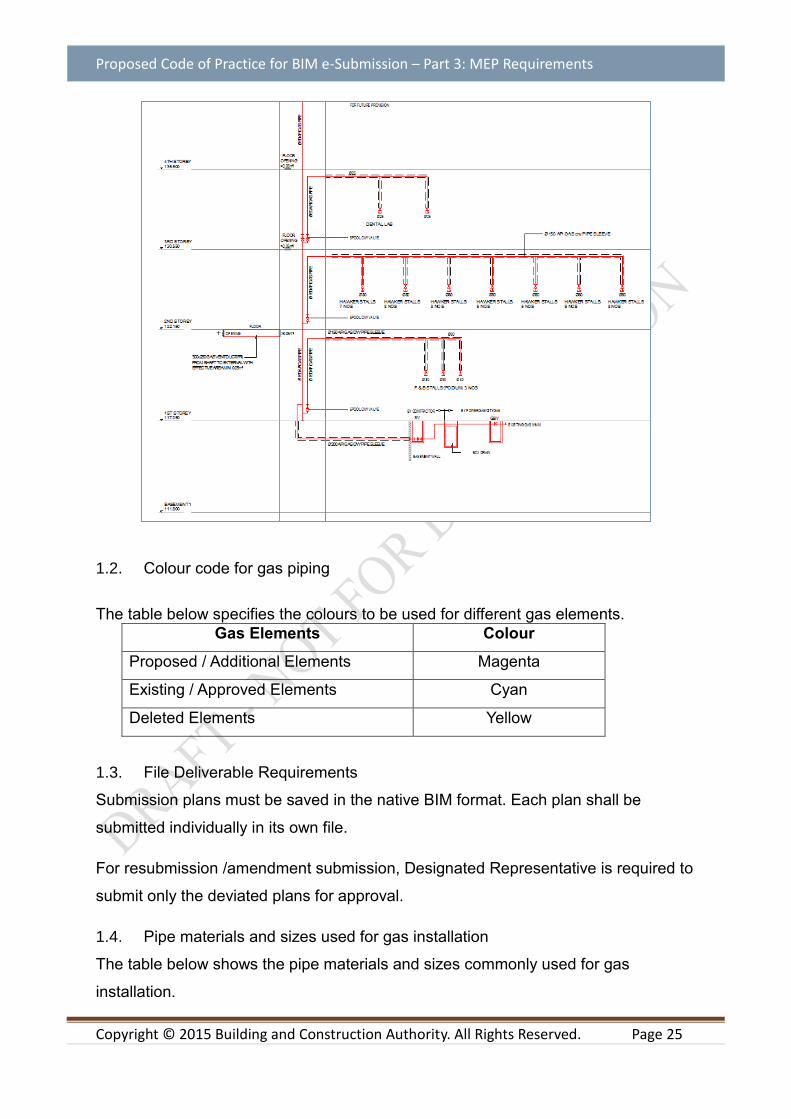
1.1.4. Schematic Diagram and Detail plan
a. Submit schematic drawing of gas installation for each building
b. Typical detail of the gas installation (such as gas duct ventilation,
trench, box-up detail, meter installation, duckfoot support design)
Proposed Code of Practice for BIM e-Submission – Part 3: MEP Requirements
Copyright © 2015 Building and Construction Authority. All Rights Reserved. Page 25
1.2. Colour code for gas piping
The table below specifies the colours to be used for different gas elements.
Gas Elements Colour
Proposed / Additional Elements Magenta
Existing / Approved Elements Cyan
Deleted Elements Yellow
1.3. File Deliverable Requirements
Submission plans must be saved in the native BIM format. Each plan shall be
submitted individually in its own file.
For resubmission /amendment submission, Designated Representative is required to
submit only the deviated plans for approval.
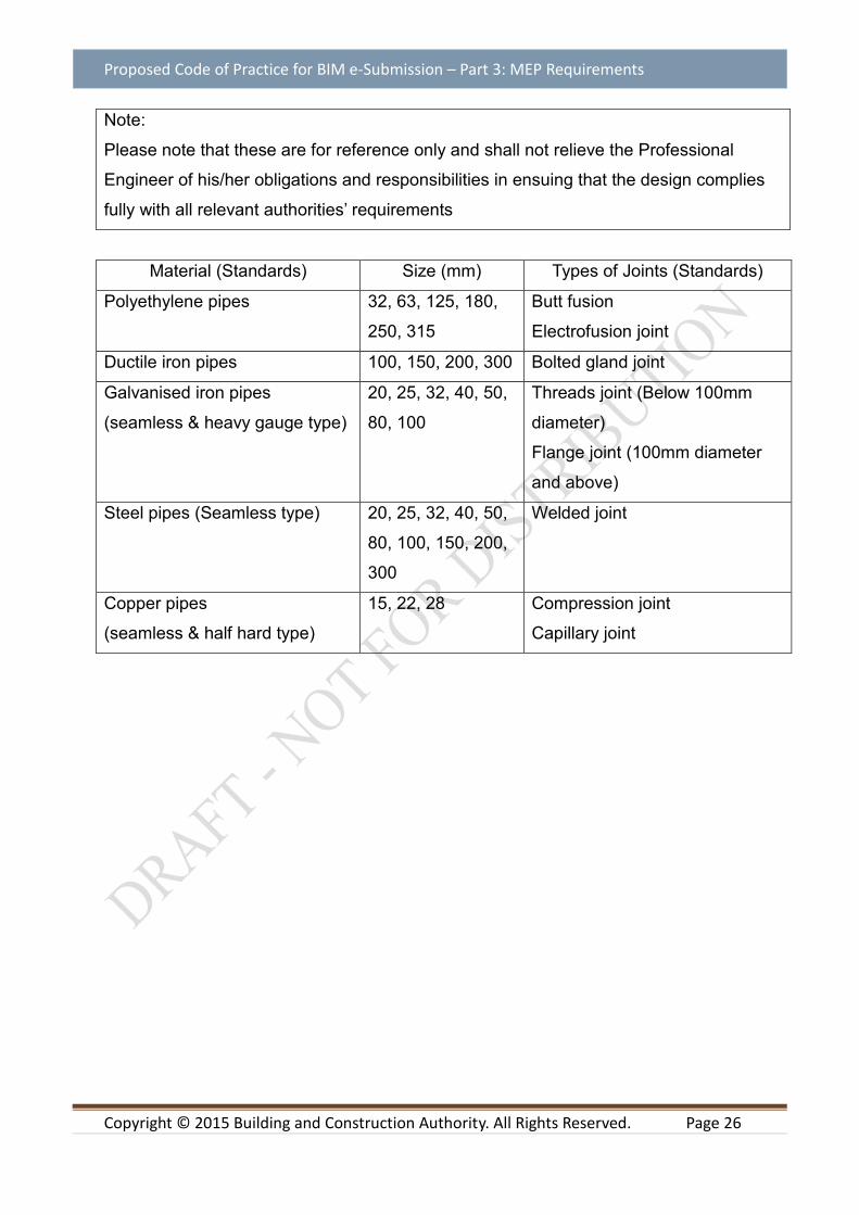
1.4. Pipe materials and sizes used for gas installation
The table below shows the pipe materials and sizes commonly used for gas
installation.
Proposed Code of Practice for BIM e-Submission – Part 3: MEP Requirements
Copyright © 2015 Building and Construction Authority. All Rights Reserved. Page 26
Note:
Please note that these are for reference only and shall not relieve the Professional
Engineer of his/her obligations and responsibilities in ensuing that the design complies
fully with all relevant authorities’ requirements
Material (Standards) Size (mm) Types of Joints (Standards)
Polyethylene pipes 32, 63, 125, 180,
250, 315
Butt fusion
Electrofusion joint
Ductile iron pipes 100, 150, 200, 300 Bolted gland joint
Galvanised iron pipes
(seamless & heavy gauge type)
20, 25, 32, 40, 50,
80, 100
Threads joint (Below 100mm
diameter)
Flange joint (100mm diameter
and above)
Steel pipes (Seamless type) 20, 25, 32, 40, 50,
80, 100, 150, 200,
300
Welded joint
Copper pipes
(seamless & half hard type)
15, 22, 28 Compression joint
Capillary joint

Proposed Code of Practice for BIM e-Submission – Part 3: MEP Requirements
Copyright © 2015 Building and Construction Authority. All Rights Reserved. Page 27
Appendix A. Step by step BIM Template guide
Refer to the separate documents for BIM Software Template Training Guide. Find the latest template training guide in https://www.corenet.gov.sg/general/building-information-modeling-(bim)-e-submission.aspx
A.1 AUTODESK REVIT
A.2 BENTLEY AECOSIM
A.3 GRAPHISOFT ARCHICAD
Copyright © 2015 Building and Construction Authority. All Rights Reserved. Page 42
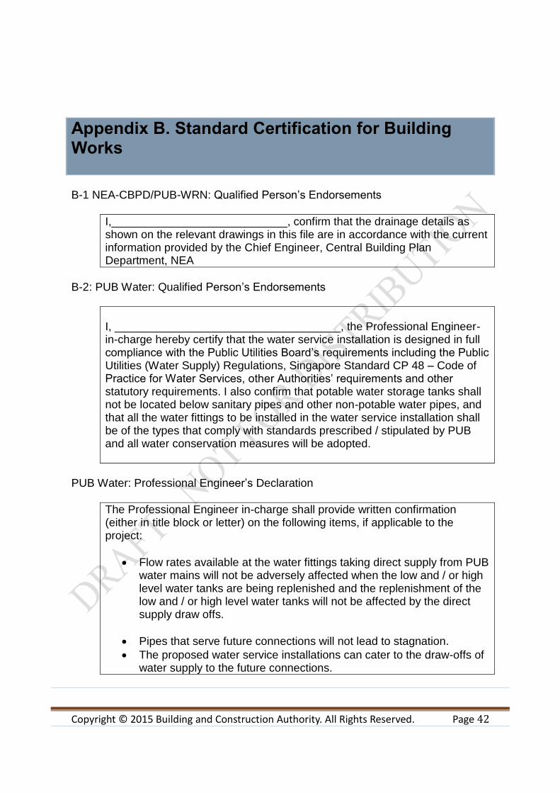
Appendix B. Standard Certification for Building Works
B-1 NEA-CBPD/PUB-WRN: Qualified Person’s Endorsements
I,____________________________, confirm that the drainage details as shown on the relevant drawings in this file are in accordance with the current information provided by the Chief Engineer, Central Building Plan Department, NEA
B-2: PUB Water: Qualified Person’s Endorsements
I, ____________________________________, the Professional Engineer-in-charge hereby certify that the water service installation is designed in full compliance with the Public Utilities Board’s requirements including the Public Utilities (Water Supply) Regulations, Singapore Standard CP 48 – Code of Practice for Water Services, other Authorities’ requirements and other statutory requirements. I also confirm that potable water storage tanks shall not be located below sanitary pipes and other non-potable water pipes, and that all the water fittings to be installed in the water service installation shall be of the types that comply with standards prescribed / stipulated by PUB and all water conservation measures will be adopted.
PUB Water: Professional Engineer’s Declaration
The Professional Engineer in-charge shall provide written confirmation (either in title block or letter) on the following items, if applicable to the project:
Flow rates available at the water fittings taking direct supply from PUB water mains will not be adversely affected when the low and / or high level water tanks are being replenished and the replenishment of the low and / or high level water tanks will not be affected by the direct supply draw offs.
Pipes that serve future connections will not lead to stagnation.
The proposed water service installations can cater to the draw-offs of water supply to the future connections.
Copyright © 2015 Building and Construction Authority. All Rights Reserved. Page 43
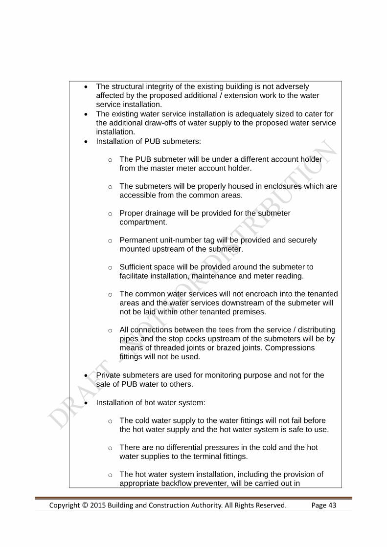
The structural integrity of the existing building is not adversely affected by the proposed additional / extension work to the water service installation.
The existing water service installation is adequately sized to cater for the additional draw-offs of water supply to the proposed water service installation.
Installation of PUB submeters:
o The PUB submeter will be under a different account holder from the master meter account holder.
o The submeters will be properly housed in enclosures which are
accessible from the common areas.
o Proper drainage will be provided for the submeter compartment.
o Permanent unit-number tag will be provided and securely
mounted upstream of the submeter.
o Sufficient space will be provided around the submeter to facilitate installation, maintenance and meter reading.
o The common water services will not encroach into the tenanted
areas and the water services downstream of the submeter will not be laid within other tenanted premises.
o All connections between the tees from the service / distributing
pipes and the stop cocks upstream of the submeters will be by means of threaded joints or brazed joints. Compressions fittings will not be used.
Private submeters are used for monitoring purpose and not for the sale of PUB water to others.
Installation of hot water system:
o The cold water supply to the water fittings will not fail before the hot water supply and the hot water system is safe to use.
o There are no differential pressures in the cold and the hot water supplies to the terminal fittings.
o The hot water system installation, including the provision of appropriate backflow preventer, will be carried out in
Copyright © 2015 Building and Construction Authority. All Rights Reserved. Page 44
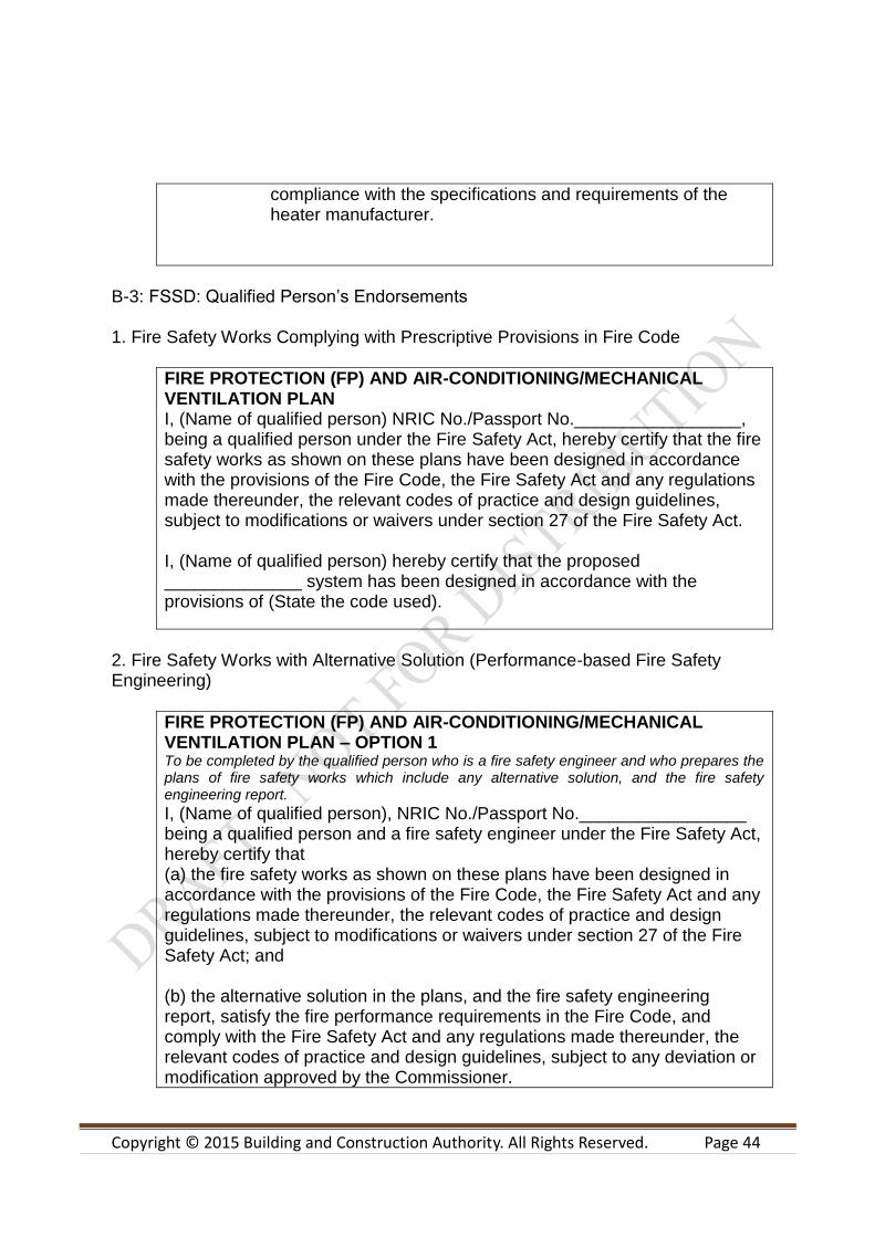
compliance with the specifications and requirements of the heater manufacturer.
B-3: FSSD: Qualified Person’s Endorsements 1. Fire Safety Works Complying with Prescriptive Provisions in Fire Code
FIRE PROTECTION (FP) AND AIR-CONDITIONING/MECHANICAL VENTILATION PLAN I, (Name of qualified person) NRIC No./Passport No._________________, being a qualified person under the Fire Safety Act, hereby certify that the fire safety works as shown on these plans have been designed in accordance with the provisions of the Fire Code, the Fire Safety Act and any regulations made thereunder, the relevant codes of practice and design guidelines, subject to modifications or waivers under section 27 of the Fire Safety Act. I, (Name of qualified person) hereby certify that the proposed ______________ system has been designed in accordance with the provisions of (State the code used).
2. Fire Safety Works with Alternative Solution (Performance-based Fire Safety Engineering)
FIRE PROTECTION (FP) AND AIR-CONDITIONING/MECHANICAL VENTILATION PLAN – OPTION 1 To be completed by the qualified person who is a fire safety engineer and who prepares the plans of fire safety works which include any alternative solution, and the fire safety engineering report.
I, (Name of qualified person), NRIC No./Passport No._________________ being a qualified person and a fire safety engineer under the Fire Safety Act, hereby certify that (a) the fire safety works as shown on these plans have been designed in accordance with the provisions of the Fire Code, the Fire Safety Act and any regulations made thereunder, the relevant codes of practice and design guidelines, subject to modifications or waivers under section 27 of the Fire Safety Act; and (b) the alternative solution in the plans, and the fire safety engineering report, satisfy the fire performance requirements in the Fire Code, and comply with the Fire Safety Act and any regulations made thereunder, the relevant codes of practice and design guidelines, subject to any deviation or modification approved by the Commissioner.
Copyright © 2015 Building and Construction Authority. All Rights Reserved. Page 45
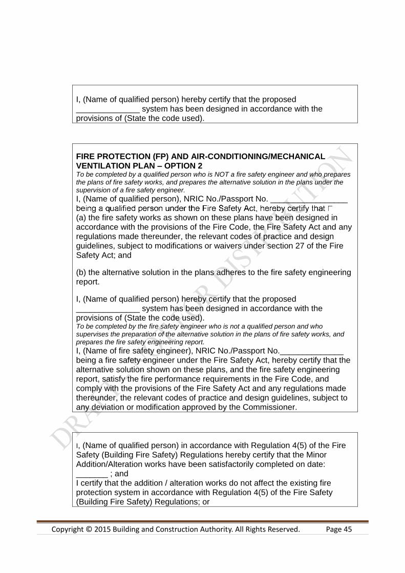
I, (Name of qualified person) hereby certify that the proposed ______________ system has been designed in accordance with the provisions of (State the code used).
FIRE PROTECTION (FP) AND AIR-CONDITIONING/MECHANICAL VENTILATION PLAN – OPTION 2 To be completed by a qualified person who is NOT a fire safety engineer and who prepares the plans of fire safety works, and prepares the alternative solution in the plans under the supervision of a fire safety engineer.
I, (Name of qualified person), NRIC No./Passport No. _________________
(a) the fire safety works as shown on these plans have been designed in accordance with the provisions of the Fire Code, the Fire Safety Act and any regulations made thereunder, the relevant codes of practice and design guidelines, subject to modifications or waivers under section 27 of the Fire Safety Act; and
(b) the alternative solution in the plans adheres to the fire safety engineering report.
I, (Name of qualified person) hereby certify that the proposed ______________ system has been designed in accordance with the provisions of (State the code used). To be completed by the fire safety engineer who is not a qualified person and who supervises the preparation of the alternative solution in the plans of fire safety works, and prepares the fire safety engineering report.
I, (Name of fire safety engineer), NRIC No./Passport No.______________ being a fire safety engineer under the Fire Safety Act, hereby certify that the alternative solution shown on these plans, and the fire safety engineering report, satisfy the fire performance requirements in the Fire Code, and comply with the provisions of the Fire Safety Act and any regulations made thereunder, the relevant codes of practice and design guidelines, subject to any deviation or modification approved by the Commissioner.
I, (Name of qualified person) in accordance with Regulation 4(5) of the Fire Safety (Building Fire Safety) Regulations hereby certify that the Minor Addition/Alteration works have been satisfactorily completed on date: _______ ; and I certify that the addition / alteration works do not affect the existing fire protection system in accordance with Regulation 4(5) of the Fire Safety (Building Fire Safety) Regulations; or

Copyright © 2015 Building and Construction Authority. All Rights Reserved. Page 46
I certify that the addition / alteration works as shown in these drawings affected the existing *sprinkler / automatic fire alarm systems and I have supervised the works on site to ensure that the said system(s) have been modified in accordance with Regulation 4(5) of the Fire Safety (Building Fire Safety) Regulations. *include whichever is applicable
B-4: IDA-TFCC: Qualified Person’s Endorsements
I, __________________________, hereby submit the proposed provision of Telecommunication Facilities for your approval. I certify that the digital information submitted is accurate for the stated development project.
B-5: CITYGAS: Qualified Person’s Endorsements
I, __________________________the designated representative of the project, hereby certify that with respect to the project, the gas installation is designed to and all gas service works shall be carried out in compliance to the requirements and provisions of the latest revision of the following: a) Gas Act (Cap 116A); b) Gas (Supply) Regulations 2008; c) Gas Supply Code; d) Code of Practice for Manufactured Gas Pipe Installation, Singapore Standard, CP51:2004; e) Fire code, the Fire Safety Act and any regulations made thereunder; f) Other relevant code/standard:_______________(please specify for installation with operating pressure higher than 20KPa) g) All relevant acts, regulations, and rules which are applicable to the gas service work; I further certify that I hold a valid practising certificate/gas service worker license. The gas installation shall be designed to operate at _________barg.

Copyright © 2015 Building and Construction Authority. All Rights Reserved. Page 47
Table Formats

Copyright © 2015 Building and Construction Authority. All Rights Reserved. Page 48
Figures
Copyright © 2015 Building and Construction Authority. All Rights Reserved. Page 49
This guide is part of the Proposed Code of Practice for BIM e-Submission series:
Proposed Code of Practice for BIM e-submission
Part 1: Architectural Requirements
Part 2: Structural Requirements
Part 3: MEP Requirements
Building and Construction Authority 52 Jurong Gateway Road #11-01, Singapore 608550 (Above JEM) www.bca.gov.sg
For more information and
feedback on the Proposed Code of Practice for BIM e-submission
Series, please visit the CORENET website:
www.corenet.gov.sg


