+ All Categories
Home > Documents > PROPOSED EXPANSION OF DYE INTERMEDIATES...

PROPOSED EXPANSION OF DYE INTERMEDIATES...

Date post: 20-Mar-2018
Category:
Upload: lykhuong
View: 240 times
Download: 11 times
Share this document with a friend
97
FORM-1 for PROPOSED EXPANSION OF DYE INTERMEDIATES PLANT IN EXISTING UNIT of M/s. IS-DYESTUFF INDUSTRIES LTD. SY. NO. 576-568, VILLAGE DUDHWADA, TALUKA PADRA, DISTRICT VADODARA, GUJARAT NABL Accredited Testing Laboratory ISO 9001:2008 Certified Company Aqua-Air Environmental Engineers P. Ltd. 403, Centre Point, Nr. Kadiwala School, Ring Road, Surat - 395002 Prepared By: NABL Accredited Testing Laboratory ISO 9001:2008 Certified Company Aqua-Air Environmental Engineers P. Ltd. 403, Centre Point, Nr. Kadiwala School, Ring Road, Surat - 395002 NABL Accredited Testing Laboratory ISO 9001:2008 Certified Company Aqua-Air Environmental Engineers P. Ltd. 403, Centre Point, Nr. Kadiwala School, Ring Road, Surat - 395002 Prepared By:
Transcript

FORM-1

for

PROPOSED EXPANSION OF DYE INTERMEDIATES PLANT

IN EXISTING UNIT

of

M/s. IS-DYESTUFF INDUSTRIES LTD.

SY. NO. 576-568, VILLAGE DUDHWADA, TALUKA PADRA,

DISTRICT VADODARA, GUJARAT

NABL Accredited Testing Laboratory

ISO 9001:2008 Certified Company

Aqua-Air Environmental Engineers P. Ltd.

403, Centre Point, Nr. Kadiwala School, Ring

Road, Surat - 395002

Prepared By:

NABL Accredited Testing Laboratory

ISO 9001:2008 Certified Company

Aqua-Air Environmental Engineers P. Ltd.

403, Centre Point, Nr. Kadiwala School, Ring

Road, Surat - 395002

NABL Accredited Testing Laboratory

ISO 9001:2008 Certified Company

Aqua-Air Environmental Engineers P. Ltd.

403, Centre Point, Nr. Kadiwala School, Ring

Road, Surat - 395002

Prepared By:

APPENDIX I

(See paragraph - 6)

FORM 1

(I) Basic Information

Sr.

No.

Item Details

1. Name of the project/s IS-DYESTUFF INDUSTRIES LTD.

2. S. No. in the schedule 5(f)

3. Proposed capacity/area/length/tonnage to

be handled/command area/lease

area/number of wells to be drilled

For detail Please refer Annexure – I

4. New/Expansion/Modernization Expansion

5. Existing Capacity/Area etc. --

6. Category of Project i.e. ‘A’ or ‘B’ ‘A’

7. Does it attract the general condition? If yes,

please specify.

No

8. Does it attract the specific condition? If yes,

please specify.

No

9. Location

Plot/Survey/Khasra No. Survey No.: 576-568

Village Dudhwada

Tehsil Padra

District Vadodara

State Gujarat

10. Nearest railway station/airport along with

distance in kms.

Vadodara – 45 Km

11. Nearest Town, city, District Headquarters

along with distance in kms.

Padra - 15 km

12. Village Panchayats, Zilla Parishad,

Municipal Corporation, local body

(complete postal address with telephone

nos. to be given)

Not applicable

13. Name of the applicant IS-DYESTUFF INDUSTRIES LTD.

14. Registered Address M/s. IS-DYESTUFF INDUSTRIES LTD.

Survey No.: 576-568, Village: Dudhwada, Tal:

Padra, Dist: Vadodara, Gujarat

15. Address for correspondence: M/s. IS-DYESTUFF INDUSTRIES LTD.

20-21, Sara Niwas, Harinagar Society, Gotri

Road, Vadodara – 390007,

Gujarat, India.

Ph. No. 0265- 2396498, 2397013

Tel /Fax No. 0265-2397245

Name Mr. H. B. Rajyaguru

Designation (Owner/Partner/CEO) Sr. Manager-Environment

Address M/s. IS-DYESTUFF INDUSTRIES LTD.

20-21, Sara Niwas, Harinagar Society, Gotri

Road, Vadodara – 390007,

Gujarat, India.

Ph. No. 0265- 2396498, 2397013

Tel /Fax No. 0265-2397245

Pin Code

E-mail [email protected]

Telephone No. 0265- 2396498, 2397013

Fax No. 0265 -2397245

16. Details of Alternative Sites examined, if

any.

Location of these sites should be shown on

a topo sheet.

NA

17. Interlinked Projects NA

18. Whether separate application of interlinked

project has been submitted?

NA

19. If yes, date of submission NA

20. If no, reason NA

21. Whether the proposal involves

approval/clearance under: if yes, details of

the same and their status to be given.

(a) The Forest (Conservation) Act, 1980?

(b) The Wildlife (Protection) Act, 1972?

(c) The C.R.Z. Notification, 1991?

No

22. Whether there is any Government

Order/Policy relevant/relating to the site?

No

23. Forest land involved (hectares) NA

24. Whether there is any litigation pending

against the project and/or land in which the

project is propose to be set up?

(a) Name of the Court

(b) Case No.

(c) Orders/directions of the Court, if any

and its relevance with the proposed

project.

NA

• Capacity corresponding to sectoral activity (such as production capacity for manufacturing,

mining lease area and production capacity for mineral production, area for mineral exploration, length for linear transport infrastructure, generation capacity for power generation etc.,)

(II) Activity

1. Construction, operation or decommissioning of the Project involving actions, which will cause

physical changes in the locality (topography, land use, changes in water bodies, etc.)

Sr.

No.

Information/Checklist confirmation Yes/

No

Details thereof with approximate

quantities frates, wherever possible)

with source of information data

1.1 Permanent or temporary change in land

use, land cover or topography including

increase intensity of land use (with respect

to local land use plan)

No

1.2 Clearance of existing land, vegetation and

Buildings?

No

1.3 Creation of new land uses?

No The project site is located on level

ground, which does not require any

major land filling for area grading work.

1.4 Pre-construction investigations e.g. bore

Houses, soil testing?

Yes To be done as a part of the study.

1.5 Construction works? Yes For detail Please refer Annexure – II

1.6 Demolition works? No There will not be Demolition work at the

site.

1.7 Temporary sites used for construction

works or housing of construction workers?

No

1.8 Above ground buildings, structures or

earthworks including linear structures, cut

and fill or excavations

Yes For detail Please refer Annexure – II

1.9 Underground works mining or tunneling? No

1.10 Reclamation works? No

1.11 Dredging? No

1.12 Off shore structures? No

1.13 Production and manufacturing processes?

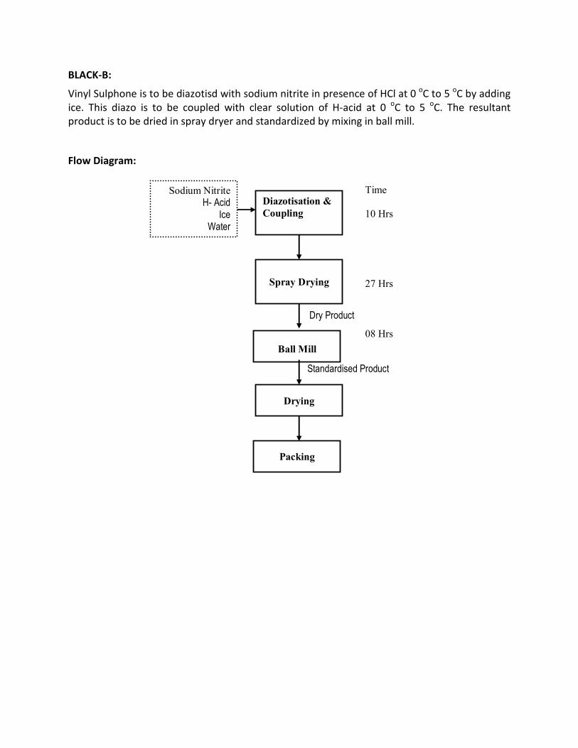
Yes For detail Please refer Annexure -III

1.14 Facilities for storage of goods or materials?

Yes Areas for storage tank farm, raw

materials and finished products will be

developed for the proposed project.

1.15 Facilities for treatment or disposal of solid

waste or liquid effluents?

Yes Facilities for treatment or disposal of

liquid effluents are given as Annexure –

V & Facilities for treatment or disposal

of solid waste is given as Annexure –VI.

1.16 Facilities for long term housing of

operational workers?

No The unit shall be running round the

clock. The operational staff will be

recruited locally and working in shift,

hence no housing for the operational

workers.

1.17 New road, rail or sea traffic during

Construction or Operation?

No There will not be any new road/rail or

sea traffic during construction or

operational phase.

1.18 New road, rail, air waterborne or other No

transport infrastructure including new or

altered routes and stations, ports, airports

etc?

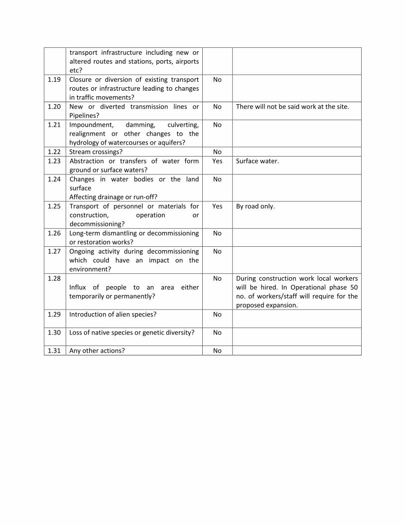
1.19 Closure or diversion of existing transport

routes or infrastructure leading to changes

in traffic movements?

No

1.20 New or diverted transmission lines or

Pipelines?

No There will not be said work at the site.

1.21 Impoundment, damming, culverting,

realignment or other changes to the

hydrology of watercourses or aquifers?

No

1.22 Stream crossings? No

1.23 Abstraction or transfers of water form

ground or surface waters?

Yes Surface water.

1.24 Changes in water bodies or the land

surface

Affecting drainage or run-off?

No

1.25 Transport of personnel or materials for

construction, operation or

decommissioning?

Yes By road only.

1.26 Long-term dismantling or decommissioning

or restoration works?

No

1.27 Ongoing activity during decommissioning

which could have an impact on the

environment?

No

1.28

Influx of people to an area either

temporarily or permanently?

No During construction work local workers

will be hired. In Operational phase 50

no. of workers/staff will require for the

proposed expansion.

1.29 Introduction of alien species?

No

1.30 Loss of native species or genetic diversity?

No

1.31 Any other actions? No

2. Use of Natural resources for construction or operation of the Project (such as land, water,

materials or energy, especially any resources which are non-renewable or in short supply):

Sr.

No.

Information/checklist confirmation Yes/No Details there of (with approximate quantities

frates, wherever possible) with source of

information data

2.1 Land especially undeveloped or agricultural

land (ha)

No The land is of Industrial Use

2.2 Water (expected source & competing users)

unit: KLD

Yes Water Source – Narmada Water Supply

For detail water balance is referred as

Annexure – IV

2.3 Minerals (MT) NO

2.4 Construction material - stone, aggregates,

and / soil (expected source - MT)

Yes Construction materials, like steel, cement,

crushed stones, sand, rubble, etc. required for

the project shall be procured from the local

market of the region.

2.5 Forests and timber (source - MT) No.

2.6 Energy including electricity and fuels

(source, competing users) Unit: fuel (MT),

energy (MW)

Yes Fuel

Fuel

LDO- 3000 Liter/Month (Existing)

HSD/LDO-25 MT/Hr (Existing)

Coal -38 MT/Day (Proposed)

FO-8 KL/Day (Proposed)

Energy :

2.5 MW from MGVCL

2.0 MW (1 MW Each) –D.G.Set

2.7 Any other natural resources (use

appropriate standard units)

No

3. Use, storage, transport, handling or production of substances or materials, which could be

harmful to human health or the environment or raise concerns about actual or perceived risks to

human health.

Sr.

No.

Information/Checklist confirmation Yes/No Details there of (with approximate

quantities/rates, wherever possible) with

source of information data

3.1 Use of substances or materials, which are

hazardous (as per MSIHC rules) to human

health or the environment (flora, fauna,

and water supplies)

Yes For details please refer Annexure – VIII

3.2 Changes in occurrence of disease or affect

disease vectors (e.g. insect or water borne

diseases)

No

3.3 Affect the welfare of people e.g. by

changing living conditions?

Yes Direct/Indirect employment

3.4 Vulnerable groups of people who could be

affected by the project e.g. hospital

patients, children, the elderly etc.

No

3.5 Any other causes No

4. Production of solid wastes during construction or operation or decommissioning (MT/month)

Sr.

No.

Information/Checklist confirmation Yes/No Details there of (with approximate

quantities/rates, wherever possible) with

source of information data

4.1 Spoil, overburden or mine wastes

No

4.2 Municipal waste (domestic and or

commercial wastes)

No

4.3 Hazardous wastes (as per Hazardous Waste

Management Rules)

Yes Please refer Annexure –VI

4.4 Other industrial process wastes

No Please refer Annexure –VI

4.5 Surplus product

No

4.6 Sewage sludge or other sludge from

effluent treatment

Yes

Please refer Annexure – VI

4.7 Construction or demolition wastes

No

4.8 Redundant machinery or equipment

No

4.9 Contaminated soils or other materials

No

4.10 Agricultural wastes

No

4.11 Other solid wastes Yes Please refer Annexure –VI

5. Release of pollutants or any hazardous, toxic or noxious substances to air (Kg/hr)

Sr. No. Information/Checklist confirmation Yes/No Details there of (with approximate

quantities/rates, wherever possible) with

source of information data

5.1 Emissions from combustion of fossil fuels

from stationary or mobile sources

Yes For details Please refer Annexure – VII.

5.2 Emissions from production processes

Yes Stack emission will remain within the norms

prescribed by CPCB. Please refer as Annexure –

VII.

5.3 Emissions from materials handling

storage or transport

Yes For details Please refer Annexure – VII.

5.4 Emissions from construction activities

including plant and equipment

No

5.5 Dust or odors from handling of materials

including construction materials, sewage

and waste

No Due to construction & vehicle movement dust

emission is likely to occur.

5.6 Emissions from incineration of waste No

5.7 Emissions from burning of waste in open

air (e.g. slash materials, construction

debris)

No

5.8 Emissions from any other sources No

6. Generation of Noise and Vibration, and Emissions of Light and Heat:

Sr. No. Information/Checklist confirmation Yes/No Details there of (with approximate

quantities/rates, wherever possible) with

source of information data with source of

information data

6.1 From operation of equipment e.g.

engines, ventilation plant, crushers

Yes The Noise level will be within the prescribed

limit. Adequate preventive & control measures

will be taken at noisy area. No significant

noise, vibration or emission of light & heat

from the unit.

6.2 From industrial or similar processes Yes -do-

6.3 From construction or demolition No

6.4 From blasting or piling No

6.5 From construction or operational traffic No

6.6 From lighting or cooling systems Yes Adequate Lighting is provided in unit and

also local ventilation system is provided.

6.7 From any other sources No

7. Risks of contamination of land or water from releases of pollutants into the ground or into

sewers, surface waters, groundwater, coastal waters or the sea:

Sr. No. Information/Checklist confirmation Yes/No Details there of (with approximate

quantities/rates, wherever possible) with

source of information data

7.1 From handling, storage, use or spillage of

hazardous materials

Yes For detail please refer Annexure – VIII

7.2 From discharge of sewage or other

effluents to water or the land (expected

mode and place of discharge)

No

7.3 By deposition of pollutants emitted to air

into and or into water

No

7.4 From any other sources No

7.5 Is there a risk of long term build up of

pollutants in the environment from these

sources?

No

8. Risk of accidents during construction or operation of the Project, which could affect human

health or the environment

Sr. No. Information/Checklist confirmation Yes/No Details there of (with approximate

quantities/rates, wherever possible) with

source of information data

8.1 From explosions, spillages, fires etc. from

storage, handling, use or production of

hazardous substances

Yes For detail please refer Annexure – VIII

8.2 From any other causes No

8.3 Could the project be affected by natural

disasters causing environmental damage

(e.g. floods, earthquakes, landslides,

cloudburst etc)?

No

9. Factors which should be considered (such as consequential development) which could lead to

environmental effects or the potential for cumulative impacts with other existing or planned

activities in the locality

Sr. No.

Information/Checklist confirmation

Yes/No

Details there of (with approximate

quantities/rates, wherever possible) with

source of information data

9.1 Lead to development of supporting. lities, ancillary development or development stimulated by the project which could have impact on the environment e.g.

• Supporting infrastructure (roads,

power supply, waste or waste water

treatment, etc.)

• housing development

• extractive industry

• supply industry

• other

Yes For detail please refer Annexure – IX

9.2 Lead to after-use of the site, which

could have an impact on the

environment

No

9.3 Set a precedent for later developments No

9.4 Have cumulative effects due to

proximity to other existing or planned

projects with similar effects

No

(II) Environmental Sensitivity

Sr. No. Areas Name/

Identity

Aerial distance (within 15km.) Proposed

project location boundary

1 Areas protected under international

conventions, national or local legislation for

their ecological, landscape, cultural or other

related value

- No protected area within 15 km from the

proposed project boundary

2 Areas which important for are or sensitive

Ecol logical reasons - Wetlands, watercourses

or other water bodies, coastal zone,

biospheres, mountains, forests

- NA

3 Area used by protected, important or

sensitive

Species of flora or fauna for breeding,

nesting, foraging, resting, over wintering,

migration

-- No protected area or sensitive species

within 15 km from the proposed project

boundary

4 Inland, coastal, marine or underground

waters

- NA

5 State, National boundaries

- N.A.

6 Routes or facilities used by the public for

access to recreation or other tourist, pilgrim

areas

- N.A.

7 Defense installations - N.A.

8 Densely populated or built-up area - -

9 Area occupied by sensitive man-made land

uses Hospitals, schools, places of worship,

community facilities)

- N.A.

10 Areas containing important, high quality or

scarce resources (ground water resources,

surface resources, forestry, agriculture,

fisheries, tourism, minerals)

- N.A.

11 Areas already subjected to pollution

environmental damage. (those where existing

legal environmental standards are

exceeded)or

- N.A.

12 Are as susceptible to natural hazard which

could cause the project to present

environmental problems (earthquake,

subsidence, landslides, flooding erosion, or

extreme or adverse climatic conditions)

- N.A.

IV). Proposed Terms of Reference for EIA studies: For detail please refer Annexure – X.

I hereby give an undertaking that, the data and information given in the application and

enclosures are true to the best of my knowledge and belief and I am aware that if any part

of the data and information submitted is found to be false or misleading at any stage the

project will be rejected and clearance give, if any to the project will be revoked at our risk

and cost.

Date: 09.05.2016

Place: Vadodara

FOR IS-DYESTUFF INDUSTRIES LTD.

AUTHORISED SIGNATORY

NOTE:

1. The projects involving clearance under Coastal Regulation Zone Notification, 1991 shall

submit with the application a C.R.Z. map duly demarcated by one of the authorized agencies,

showing the project activities, w.r.t. C.R.Z. (at the stage of TOR) and the recommendations of

the State Coastal Zone Management Authority (at the stage of EC). Simultaneous action shall

also be taken to obtain the requisite clearance under the provisions of the C.R.Z. Notification,

1991 for the activities to be located in the CRZ.

2. The projects to be located within 10 km of the National Parks, Sanctuaries, Biosphere

Reserves, Migratory Corridors of Wild Animals, the project proponent shall submit the map duly

authenticated by Chief Wildlife Warden showing these features vis-à-vis the project location

and the recommendations or comments of the Chief Wildlife Warden thereon (at the stage of

EC).

3. All correspondence with the Ministry of Environment & Forests including submission of

application for TOR/Environmental Clearance, subsequent clarifications, as may be required

from time to time, participation in the EAC Meeting on behalf of the project proponent shall be

made by the authorized signatory only. The authorized signatory should also submit a

document in support of his claim of being an authorized signatory for the specific project.

LIST OF ANNEXURES

SR. NO. NAME OF ANNEXURE

I List of Products with their Production Capacity

II Layout Map of the Plant

III Brief Manufacturing Process Description

IV Details of Water Consumption & Waste water Generation

V Details of Treatment Scheme and Disposal

VI Details of Hazardous /Solid Waste Generation, Handling and Disposal

VII Details of Stack and Vent

VIII Details of Hazardous Chemical Storage & Handling

IX Socio-Economic Impacts

X Proposed Terms of Reference for EIA studies

ANNEXURE-I

___________________________________________________________________________

LIST OF PRODUCTS WITH THEIR PRODUCTION CAPACITY

SR.

NO. PRODUCTS CATEGORY

PRODUCTION CAPACITY

(MT/MONTH)

EXISTING

TOTAL AFTER

PROPOSED

EXPANSION

1. Sulpho Tobias Acid Dye Intermediates

30 30

2. H-Acid - 4,667

DASA

K-Acid

Sulphonation of Ortho Nitro

Toluene / Para Nitro

Toluene

Vinyl Sulphon & its

derivatives

Tobias Acid

Vinyl Sulphon Condense &

its derivatives

DMA base Vinyl Sulphon

PC base Vinyl Sulphon

OA base Vinyl Sulphon

Sulpho base Vinyl Sulphon

PMP base Vinyl Sulphon

Benzanilide base Vinyl

Sulphon

J-Acid

MPDSA

Meta urido Aniline

Gamma Acid

4-Sulpho Anthranilic

Acid(Hydrazone)

5-Sulpho Anthranilic

Acid(Hydrazone)

Aniline 2,4 disulphonic Acid

MPDDSA

CPC

Chloryl condense

6 Acetyl OAPSA

Beta Naphthol

NMJ Acid

2-Pyridone

Sulpho J-Acid

3. Synthetic Organic dyes Dyes - 3,000

Total 30 7,697

LIST OF BY - PRODUCTS ALONG WITH PRODUCTION CAPACITY

SR.

NO.

NAME PRODUCTION CAPACITY

(MT/MONTH)

EXISTING PROPOSED

1 Hydrochloric Acid (30%) - 6,979

2 Sodium Bisulfite (35%) - 4,200

3 Liquor Ammonia (20%) - 5615

4 Spent Acid (23-25%) 194 17888

ANNEXURE-II

___________________________________________________________________________

LAYOUT MAP OF THE PLANT

SO3H SO3H

NH2 SO3H NH2

SO3H

OLEUM 23% [TEMP 30 C]

TOBIAS ACID SULPHO TOBAIS ACID

ANNEXURE-III

________________________________________________________________________

BRIEF PROCESS DESCRIPTION

1 SULPHO TOBIAS ACID

1.1 PROCESS DECRIPTION

Tobias Acid is sulphonated with 23% Oleum and the sulphonated mass are drowned in ice,

common salt and water. The mass is then filtered; centrifuged and wet cake of Sulpho Tobias is

obtained.

1.2 CHEMICAL REACTION

1.3 MATERIAL BALANCE

Sulphonation

Drowning

Centrifuge

Filtration

Final Product

1520 Kg

Tobias Acid 840 kg

Oleum 2500 kg

Sulphuric acid 300 kg

Water 6820 kg

Common Salt 900 kg

Spent Acid (23-25 %) 9685 kg

SO2 for scrubbing

Spent Acid (23-25 %) 155 kg

2 H-ACID

2.1 PROCESS DECRIPTION

The process steps involve Sulphonation, Nitration, Neutralization, Filtration, Reduction,

concentration, Autoclaving and Isolation.

(a) Sulphonation: - Naphthalene is charged in the Cast Iron sulphonator and sulphuric acid with

oleum is charged at low temperature to have reaction with monohydrated acid. The reaction

mass is then heated to 1700C and 65% Oleum is charged. The temperature is maintained for

about 3 hours. On completion of the reaction it is taken for nitration.

(b) Nitration: - Nitration is carried out in CI vessels. The Sulphonated mass is reacted with Nitric

acid at controlled temperature. The mass is then taken to neutralizer.

(c) Neutralization: - This reaction is carried out in a MSRL brick lined vessel. The excess acid is

reacted with limestone to get gypsum.

(d) Filtration: - The gypsum is then precipitated out and separated in horizontal vacuum filter

and is thoroughly washed with water.

(e) Reduction: - The nitro mass thus obtained is reduced to amino compound by iron powder

and HCl in hot condition. After completion of the reaction the mass is filtered to remove iron

oxide sludge.

(f) Concentration: - The amino solution is concentrated in the multiple effect evaporators to a

desired level for hydrolysis.

(g) Autoclaving: - The concentrated mass is hydrolyzed under pressure of 6-7 kg/cm2 with

caustic soda at a temperature of 1700C.

(h) Isolation: - The hydrolyzed product obtained from the autoclave is reacted with sulphuric

acid or HCl for an acidic pH of about 2. H-Acid is thereby precipitated and filtered through

vacuum filters and washed to obtain wet cake of H-Acid. The wet cake is finally dried to get the

product.

2.2 CHEMICAL REACTION

2.3 MATERIAL BALANCE

Sulphonation

Nitration

Reduction

Filtration

Evaporator

Filtration

Neutralizer

Fusion

Final Product

2250 Kg

Naphthalene 1800 kg

Sulphuric Acid 3660 kg

Oleum 5400 kg

Nitric Acid 2175 kg

Caustic Lye 450 kg

LSP 8750 kg

Glauber Salt 2700 kg

Water 6500 kg

NOx 1350 kg

Gypsum 6000 kg

Cl Powder 1750 kg

Acetic Acid 350 kg

Soda Ash 950 kg

Iron Sludge 500 kg

Water Recovery 10000 kg

Methanol 4320 kg

Caustic Flakes 3600 kg

Isolation Spent Acid 18000 kg

Sulphuric Acid 1920 kg

Water 2250 kg

SBS Recovery 2025 kg

Filtration Mother Liquor 23300 kg

Centrifuge

3 DASA

3.1 PROCESS DESCRIPTION

The reaction steps involve Sulphonation of Acetanilide using acetanilide and Chlorosulphonic

acid as raw material. The sulphonated mass is dumped in Ice to obtain wet cake of Acetanilide

Sulphonyl chloride. On the other side reduction of paranitroaniline to Para phenyl diamine is

carried out with the help of Iron and Soda ash. The Para phenyl diamine and Acetanilide

Sulphonyl chloride obtained from above reactions are taken for condensation by soda ash,

followed by Isolation to obtain the product DASA.

3.2 CHEMICAL REACTION

3.3 MATERIAL BALANCE

STAGE 1 (SULPHONATION OF ACETANILIDE)

STAGE 2 (P.N.A TO P.P.D)

STAGE 3 (CONDENSATION AND HYDROLYSIS)

Sulphonation

Dumping

ASC Wet Cake

9620 kg

Chlorosulphonic Acid 2700 kg

Acetanilide 600 kg

Ice 10000 kg Spent Acid 3520 kg

HCl 160 kg

Reduction

Filtration

PPD Solution

6555 kg

Para Nitro Aniline 500 kg

Iron 625 kg

Water 2000 kg

HCl 650 kg

Soda Ash 140 kg

Ice 2000 kg

Water 2000 kg Fe2O3 wet cake 1300 kg

CO2 60 kg

Condensation

Isolation

Final Product

1000 kg

PPD 6555 kg

ASC 9620 kg

NaOH 400 kg

Water 7000 kg

Soda Ash 260 kg

Spent Acid 2000 kg

Washing Water 5900 kg Acidic Effluent 14000 kg

CO2 110 kg

Spent Acid 16625 kg

4 K-ACID

4.1 PROCESS DESCRIPTION

(a) G salt preparation. Beta-naphthol is reacted with oleum and H2SO4 and maintained at 70-

750C for 7 to 8 hrs. The mass is then taken for isolation with salt and water. This is followed by

filtration and centrifuging.

(b) Amino G acid step: Amination is carried out of G salt by reacting it with liquid Ammonia and

Sodium bisulphate. The mass is taken then for isolation by H2SO4.This is followed by filtration to

obtain Amino G acid.

(c) K acid step: Amino G acid is Sulphonated with the help of oleum and H2SO4.Ths is followed

by isolation filtration and centrifuging to finally obtain k acid.

4.2 CHEMICAL REACTION

4.3 MATERIAL BALANCE

Sulphonator

Drowning

W/C G-Salt

Autoclave

Isolator

Centrifuge

Filtration

Filtration

Final Product 1550 Kg

B-Naphthol 800 kg

Sulphuric Acid 960 kg

Oleum (23%) 1600 kg

Water 4500 kg

Salt 1280 kg

ML to ETP 670 kg

Liquor Ammonia 952 kg

SBS 211 kg

NH3 Scrubbed

Dil. H2SO4 (40%) 470 kg

Water 1950 kg

Centrifuge ML to incineration 340 kg

W/C Amido G Acid

Filtrate for R Salt recovery 6660 kg

Filtrate for crystallizer incineration 3823 kg

SO2 Scrubbed

Sulphonation Sulphuric Acid (98%) 818 kg

Oleum (65%) 2912 kg

SO2 Scrubbed

Isolation Water 6500 kg

Salt 364 kg

Evaporation Loss 400 kg

Filtration

Centrifuge

Filtrate as spent acid 9100 kg

ML to ETP 774 kg

98

178

o-Nitro Toluene Sulphonated Sulfuric Acid

o-NT

137 217 98

CH3NO2

H2SO4

H2S2O7

CH3NO2

SO3H

+ H2SO4

ONT 137

H2SO4 98

H2S2O7 178

413

Water 18

Common Salt 117

(NaCl) 548

Spent Acid (25%)

Filteration (Water+Salt+Sulfuric Acid)

217 331

Centrifuge 2

(Recycle to Drawning Vessel)

Wet Cake

215

Sulfonator

Drawning

Vessel

5 SULFONATION (OF ONT/PNT)

5.1 PROCESS DESCRIPTION

Take ONT/PNT in as sulfonator and charge 98% Sulphuric Acid and 65% Oleum in it slowly. After

completion of reaction blow sulfomass in another vessel containing water, charge common salt,

mix it, cool it and filter in netucsh. Material is then centrifuge. Collect filtrate as Spent Sulphuric

Acid for sale. Sulphonated ONT/PNT from centrifuge is then packed in HDPE bags and sent for

sale.

5.2 CHEMICAL REACTION

5.3 MATERIAL BALANCE:

* All figures are in kgs

6 VINYL SULPHON & ITS DERIVATIVES

6.1 PROCESS DESCRIPTION

Chloro Sulphonation:

Chloro Sulphonic Acid is charged into the Sulphonation reactor. Acetanilide is then slowly added

to maintain the temperature below 80° C. The temperature is then maintained between 50-60

°C. The batch thus prepared is transferred to the storage tank.

Dumping:

Sulphonated mass is charged into the Reactor cooled with brine. Ice water is then added slowly

to remove all the HCl formed due to decomposition of excess Chloro Sulphonic Acid. The HCl is

scrubbed and absorbed in water to make HCl. Further Ice water is added to dilute the

concentrated Sulfuric Acid formed due to the decomposition of Chloro Sulphonic Acid. Here we

get of Sulfuric Acid of strength 30-40%. The mass is then filtered out (ASC Cake).

Reduction:

Sodium Bi Sulphite slurry is added to the reactor. The pH is maintained neutral by adding

Caustic Lye. The ASC wet cake is then charged under controlled temperature and pH. After

addition is over the temperature is raised up to 50 °C. The mass is then filtered and transferred

to condensation vessel.

Condensation:

The reduction mass in condensation vessel is maintained at 50°C. Ethylene Oxide is slowly

added. The pH is maintained to 5-7 by adding dilute sulphuric acid. The material after

condensation is transferred to the Nutsche Filter. The Mother liquor is stored in storage tank.

The condensed product is then washed and dried.

Esterification:

The condensed product is charged in Esterification reactor. Concentrated Sulphuric Acid is

added. The temperature is then raised and maintained at 160°C for 4 hours. Vacuum is applied

to take out acetic acid vapors and being condensed. The product is then collected a tank. The

dried Vinyl Sulphone is pulverized and packed in PVC bags.

NHCOCH3

+ 2Cl.SO3H

ACETANILIDE

NHCOCH3

+

SO2Cl

HCl + H2SO4

CHLORO SULPHONIC ACID

NHCOCH3

+

SO2Cl

NaOH + NaHSO3

NHCOCH3

+

SO2Na

Na2SO4 + NaCl

NHCOCH3

+

SO2Na

H2SO4+ H2O

O

H2C CH2

+

NHCOCH3

SO2CH2CH2OH

+ Na2SO4

ETHYLENE OXIDE

NHCOCH3

SO2CH2CH2OH

+ H2SO4

NH2

SO2CH2CH2OSO3H

+ CH3COOH

VINYL SULPHONE

6.2 CHEMICAL REACTION

Chloro Sulphonation:

Reduction:

Ethoxylation:

Esterification:

6.3 MATERIAL BALANCE

Acetanilide 2182

CHLOROSULPHONIC

ACID10182

12364

Ice 14545 DUMPING(ICE)

26909

FILTERATION(Nutch) H2SO4 (35-40%)

12364 14545

SOD. BISULPHITE

SLURRY(30%)6545

CAUSTIC LYE 2182

21091

PRODUCT FROM FILT

ETHYLENE OXIDE 1018

H2SO4 2269.00

24378.00

Salt

FILTER 17753

SODIUM SULPHITE

SALT

(BYPRODUCT)

8299

6625.00

ETP

CONDENSED PRODUCT 9454

6625.00

2262 MOISTURE LOSS

DRYER

4363.00

PRODUCT FROM

Dryer

H2SO4 1455 ESTERIFICATION

5818.00

ACETIC ACID

1818

VINYL SULPHONE

4000.0

CHLOROSULPHONATION

REDUCTION

ETHOXYLATION

MASS BALANCE/FLOW CHART OF THE VINYL SULPHONE

SULPHONATION

SO3H

OH OH

B NAPTHOL OXY TOBIAS ACID

AMIDATION

SO3H SO3H

AMMONIA/AMMONIUM SULFATE

OXY TOBIAS ACID TOBIAS ACID

CLSO3H

NH2OH

7 TOBIAS ACID

Beta Naphthol is sulphonated with Ethylene Dichloride with Chlorosulphonic acid .The

Sulphonation mass is drowned into ice and water and Ethylene Dichloride layer is settled out

and separated. The aqueous layer is made alkaline with caustic soda liquor and Soda ash and

the remaining Dichloride is removed by distillation. The oxy Tobias is aminated in presence of

Ammonium sulfite, ammonium Sulfate and Ammonia under the pressure. The mass is filtered

and Tobias Acid is precipitated form the clear filtrate with sulfuric acid. The precipitated Tobias

acid is filtered washed and dried in vacuum.

7.2 CHEMICAL REACTION

7.3 MATERIAL BALANCE

Sulphonation

Drowning

Amidation

Filtration

Isolation

Oxytobias Acid

Separator

Drying

B-Naphthol 1188 kg

Chlorosulphonic Acid 995 kg

EDC 5166 kg

Ammonia 1700 kg

Sulphuric Acid 750 kg

Ammonium Sulphate 1000 kg

Liquor SO2 1000 kg

Hydrated Lime 2075 kg

Caustic Soda Lye 250 kg

Water 750 kg

Sulphuric Acid (40%) 250 kg

Ammonia recovered 1540 kg

Ice 1100 kg

Filtration

HCl 640 kg

EDC recovered 5000 kg

Water 600 kg Acidic Effluent 2% to ETP 1000 kg

Soda Ash 36 kg

Caustic Liquor 407 kg

Water 241 kg

Water 500 kg

Gypsum sludge 6000 kg

Final Product

8 VINYL SULPHON CONDENSE & ITS DERIVATIVES

8.1 process description

Chloro Sulphonation:

Chloro Sulphonic Acid is charged into the Sulphonation reactor. Acetanilide is then slowly added

to maintain the temperature below 80° C. The temperature is then maintained between 50-60

°C. The batch thus prepared is transferred to the storage tank.

Dumping:

Sulphonated mass is charged into the Reactor cooled with brine. Ice water is then added slowly

to remove all the HCl formed due to decomposition of excess Chloro Sulphonic Acid. The HCl is

scrubbed and absorbed in water to make HCl. Further Ice water is added to dilute the

concentrated Sulfuric Acid formed due to the decomposition of Chloro Sulphonic Acid. Here we

get of Sulfuric Acid of strength 30-40%. The mass is then filtered out (ASC Cake).

Reduction:

Sodium Bi Sulphite slurry is added to the reactor. The pH is maintained neutral by adding

Caustic Lye. The ASC wet cake is then charged under controlled temperature and pH. After

addition is over the temperature is raised up to 50 °C. The mass is then filtered and transferred

to condensation vessel.

Condensation:

The reduction mass in condensation vessel is maintained at 50°C. Ethylene Oxide is slowly

added. The pH is maintained to 5-7 by adding dilute sulphuric acid. The material after

condensation is transferred to the Nutsche Filter. The Mother liquor is stored in storage tank.

The condensed product is then washed and dried.

Esterification:

The condensed product is charged in Esterification reactor. Concentrated Sulphuric Acid is

added. The temperature is then raised and maintained at 160°C for 4 hours. Vacuum is applied

to take out acetic acid vapors and being condensed. The product is then collected a tank. The

dried Vinyl Sulphone is pulverized and packed in PVC bags.

NHCOCH3

+ 2Cl.SO3H

ACETANILIDE

NHCOCH3

+

SO2Cl

HCl + H2SO4

CHLORO SULPHONIC ACID

NHCOCH3

+

SO2Cl

NaOH + NaHSO3

NHCOCH3

+

SO2Na

Na2SO4 + NaCl

NHCOCH3

+

SO2Na

H2SO4+ H2O

O

H2C CH2

+

NHCOCH3

SO2CH2CH2OH

+ Na2SO4

ETHYLENE OXIDE

8.2 CHEMICAL REACTION

Chloro Sulphonation:

Reduction:

Ethoxylation:

Acetanilide 2182

CHLOROSULPHONIC

ACID10182

12364

Ice 14545 DUMPING(ICE)

26909

FILTERATION(Nutch) H2SO4 (35-40%)

12364 14545

SOD. BISULPHITE

SLURRY(30%)6545

CAUSTIC LYE 2182

21091

PRODUCT FROM FILT

ETHYLENE OXIDE 1018

H2SO4 2269.00

24378.00

Salt

FILTER 17753

SODIUM SULPHITE

SALT

(BYPRODUCT)

8299

6625.00

ETP

CONDENSED PRODUCT 9454

6625.00

2262 MOISTURE LOSS

DRYER

4363.00

CHLOROSULPHONATION

REDUCTION

ETHOXYLATION

8.3 MATERIAL BALANCE

9 DMA BASE VINYL SULPHON

9.1 PROCESS DESCRIPTION

Dimethoxy Aniline is charged into Chlorosulphonic acid below 300C. After the addition the

temperature is raised to 50-550C and maintained for 4 hrs. It is cooled and drowned over ice

and filtered. The sulphochloride is charged into a slurry of sodium bisulphate and made neutral

with caustic and the pH is maintained at 7.Eyhylene oxide is passed into the solution

maintaining pH 7 by adding H2SO4.When the reaction is complete, it is filtered and dried .It is

further clarified by heating with calculated quantity of H2SO4 and then pulverized.

9.2 CHEMICAL REACTION

9.3 MATERIAL BALANCE

Acetylation

Sulphonation

Reduction

Filtration

Condensation

Filtration

Drowning

Filtration

Final Product

1215 Kg

Acetic Anhydride 840 kg

2:5 DMA 700 kg

Chlorosulphonic Acid 4500 kg

Ice 11587 kg

Spent Acid 17000 kg

SBS 550 kg

Water 1310 kg

Caustic Lye 1150 kg

Iron Sludge 10 kg

Dil. H2SO4 (40%) 600 kg

Ethylene Oxide 400 kg

Drying

Sulphuric Acid (98%) 357 kg

Water Evaporation 450 kg

Esterification Acetic Acid 192 kg

HCl 127 kg

Washing 3500 kg

Washing 1000 kg

Condensate Effluent 7500 kg

10 PC BASE VINYL SULPHONE

10.1 PROCESS DESCRIPTION

Acetyl Para Cresidine is charged into Chlorosulphonic acid below 300C. After the addition the

temperature is raised to 50-550C and maintained for 4 hrs. It is cooled and drowned over ice

and filtered. The sulphochloride is charged into a slurry of sodium bisulphate and made neutral

with caustic and the pH is maintained at 7.Eyhylene oxide is passed into the solution

maintaining pH 7 by adding H2SO4.When the reaction is complete, it is filtered and dried .It is

further clarified by heating with calculated quantity of H2SO4 and then pulverized

10.2 CHEMICAL REACTION

10.3 MATERIAL BALANCE

Acetylation

Sulphonation

Reduction

Filtration

Condensation

Filtration

Drowning

Filtration

Final Product

930 Kg

Para Cresidine 500 kg

Acetic Anhydride 640 kg

Chlorosulphonic Acid 3600 kg

Ice 9500 kg

Spent Acid 2800 kg

Spent Acid 16500 kg

SBS 400 kg

Water 1350 kg

Caustic Lye 1200 kg

Iron Sludge 10 kg

Dil. H2SO4 (40%) 600 kg

Ethylene Oxide 400 kg

Drying

Sulphuric Acid (98%) 300 kg

Water Evaporation 280 kg

Esterification Acetic Acid 180 kg

HCl 90 kg

Washing 2000 kg

Washing 1700 kg

Condensate Effluent 7000 kg

11 ORTHO ANISIDINE BASE VINYL SULPHONE

11.1 PROCESS DESCRIPTION

Acetyl Ortho Anisidine is charged into Chlorosulphonic acid below 300C. After the addition the

temperature is raised to 50-550C and maintained for 4 hrs. It is cooled and drowned over ice

and filtered. The sulphochloride is charged into a slurry of sodium bisulphate and made neutral

with caustic and the pH is maintained at 7.Eyhylene oxide is passed into the solution

maintaining pH 7 by adding H2SO4.When the reaction is complete, it is filtered and dried .It is

further clarified by heating with calculated quantity of H2SO4 and then pulverized.

11.2 CHEMICAL REACTION

11.3 MATERIAL BALANCE

Sulphonation

Dumping

Esterification

Pulverization

Ethoxylation

Reduction

Final Product

1000 Kg

Acetyl Ortho Anisidine 715 kg

Chlorosulphonic Acid 3033 kg

Ice 1941 kg

Sodium Bisulphite 650 kg

Caustic Lye 1191 kg

Sulphuric Acid 317 kg

Spent Acid (23-25%) 4270 kg

HCl 156 kg

Ethylene Oxide 585 kg

Sulfuric Acid 1069 kg

Condensate Effluent for Glauber

Salt recovery 3866 kg

Acetic Acid 209 kg

12 SULPHO BASE VINYL SULPHONE

12.1 PROCESS DESCRIPTION

Vinyl Sulphone, Sulphuric Acid, Oleum will be Sulphonated and thereafter the mass is dumped.

The mass is partially neutralized and salting is done. The mass is filtered and the cake is dried as

final product.

12.2 MATERIAL BALANCE

Sulphonation

Drowning

Filtration

Final Product

500 Kg

Sulfuric Acid 384 kg

Oleum 452 kg

VS 500 kg

Water + Ice 5664 kg

ML for reuse in H-acid 6500 kg

13 PMP VINYL SULPHONE

13.1 PROCESS DESCRIPTION

The VS condense is hydrolyzed with HCl and then the reaction mass is diazotized with sodium

Nitrite. The Diazo mass is then reduced with SBS, Caustic lye, HCl. The reduction mass is then

condensed with Methyl ester and caustic lye. The condensed mass is then filtered and the wet

cake is centrifuged and packed.

13.2 CHEMICAL REACTION

13.3 MATERIAL BALANCE

Hydrolysis

Diazotization

Filtration

Condensation

Reduction

Final Product

700 Kg

VS Condense 500 kg

HCl 680 kg

Sodium Nitrite 145 kg

Sodium Bisulphite 550 kg

Water 2500 kg

Caustic Lye 500 kg

HCl 900 kg

Washing 2500 kg

Methyl Ester 200 kg

Caustic Lye 500 kg

ML to incinerator 8275 kg

O2N COOH + SO2Cl + O2N COCl + HCl + SO2

167 116 185.5

Para nitro benzoicacid Para nitro benzoyl chloride

+

O2N COHN H2N

SO2C2H4OH

201

SO2C2H4OH

320

Acetic Acid / HCl + Fe

H2N CO - HN

SO2C2H4OH

Benzanilide V.S. (M.W. 290)

Metabase V.S.

14 BENZANILIDE BASE VINYL SULPHON

14.1 PROCESS DECRIPTION

Metabase VS is dissolved in water and clarified through dicamal bed. The solution of Metbase VS is

condensed with paranitrobenzoyl Chloride. Nitrobenanilide VS is isolated which is reduced by iron and

acetic acid is presence of methanol as solvent. Then it is distilled out. Then menthanol is also separated

and wet cake is obtained which is dired.

14.2 CHEMICAL REACTION

Water 5750 Lit. MBVS 893 Kg.

Ca CO3 270 Kg.

6913 Kg.

NBA 916 Kg.

CONDENSATION

7829 Kg.

6200 Lit.

FILTERATION

629 Kg. W/C

Iron Powder 775 Kg. Methanol 1425 Lit.

REDUCTION

Acetic Acid 65 Kg. Water 3300 Lit.

FILTERATION

Sludge 1040 Kg.

6145 Lit

Water 3800 Lit. Methanol 1470 Lit.

11424 Lit

FILTERATION

5000 Lit.

6424 Kg Wt.

DRYING 4924 Lit.

1500 Kg.

14.3 MATERIAL BALANCE

15 J-ACID

15.1 PROCESS DESCRIPTION

Tobias Acid is Sulphonated by 23% Oleum, hydrolyzed by water and the wet cake is autoclaved

with caustic flakes. After autoclaving the mass is isolated with the help of 98% H2SO4.It is then

filtered, centrifuged and dried to obtain J acid.

15.2 CHEMICAL REACTION

15.3 MATERIAL BALANCE

Sulphonation

Hydrolysis

W/C G-Salt

Isolation

Filtration

Autoclave

Filtration

Centrifuge

Final Product

720 Kg

Tobias Acid 1000 kg

Oleum (23%) 3055 kg

Water 3800 kg

Caustic Flakes 690 kg

Water 1900 kg

Caustic Lye 450 kg

Dil. H2SO4 (98%) 1125 kg

Water 4400 kg

ML to ETP 9400 kg

Filtrate 52% spent acid reused in J-acid

isolation 6300 kg

16 MPDSA

16.1 PROCESS DESCRIPTION

Sulphonation of 2:4 Dinitro chloro benzene is carried out with the help of Sodium bisulphate to

get DNBSA that is then reduced by Iron powder and HCL to obtain MPDSA.

16.2 CHEMICAL REACITON

16.3 MATERIAL BALANCE

Sulphonation

Filtration

Isolation

Filtration

Filtration

Reduction

Final Product

700 Kg

Water 3000 kg

2:4 DNCB 800 kg

MgO 150 kg

SBS 510 kg

Salt 450 kg

ML to ETP 3910 kg

HCl 100 kg

Water 2500 kg

Iron Powder 500 kg

Soda Bicarb 40 kg

Carbon 10 kg

Iron Sludge 1200 kg

Salt 2400 kg

ML to Incineration 4650 kg

17 META URIDO ANILINE

17.1 PROCESS DESCRIPTION

Meta phenyl diamine is dissolved in HCl and water maintaining temperature of 60-620C.

External heating is done for maintaining temperature of about 500C until MPD is completely

dissolved. Clear MPD solution is cooled to 200C. Pine oil and sodium cyanate are charged and

temperature kept at 200C. pH is maintained between 1.7-2.3.Then charging of sodium cyanate

and HCl is done in six lots at an interval of one and half hour. Stirring is continued till the

reaction is completed and the mass is finally taken to filter press to remove water and obtain

the product.

17.2 CHEMICAL REACTION

17.3 MATERIAL BALANCE

MPD Acidic Solution

Filtration

Centrifuge

Final Product

(50% Purity)

Sodium Cyanate 650 kg

MPD 1000 kg

HCl (30%) 1500 kg

Water 1500 kg

ML to ETP 930 kg

Washing 1000 kg

ML to Incineration 2720 kg

18 GAMMA ACID

Beta-naphthol is sulphonated with 98% H2SO4 and 23% Oleum. Sulphonation is followed by

drowning and reaction with potassium chloride. The mass is then filtered and autoclaved with

liquid Ammonia, sodium bisulphite and subsequently fusion by caustic flakes. The fused mass is

finally reacted with H2SO4 and cooled to 75-800C and finally filtered and dried.

18.1 CHEMICAL REACTION

18.3 MATERIAL BALANCE

Sulphonation

Drowning

Autoclave

Isolation

Filtration

Centrifuge

Filtration

Final Product

1160 Kg

B-Naphthol 1000 kg

Sulphuric Acid (98%) 1200 kg

Oleum (23%) 1800 kg

Liq. Ammonia 300 kg

SBS 210 kg

Caustic Flakes 1000 kg

Sulphuric Acid (98%) 2150 kg

Water 4000 kg

ML to ETP 9000 kg

Filtrate for R-Salt recovery 5000 kg

SO2 recovered

Water 3500 kg

Centrifuge

19 4 –SULPHO ANTHRANILIC ACID (HYDRAZONE)

19.1 PROCESS DESCRIPTION

Diazotization of 4-sulpho Anthranilic acid is carried out by addition of ice, HCl and Sodium

Nitrite solution. Sodium bisulphite is neutralized with caustic lye at temperature of 200C and pH

7 is attained. Diazo is then added to this solution maintaining pH of 7 and temperature 200C.

Stirring is done till diazo is negative in the coupling test. Benzaldehyde condensation is done at

right temperature with continuous stirring overnight. Excess SO2 gas is removed by adding 60%

HCl by volume and heating at 450C. The mass is then filtered and dried to obtain the product.

19.3 MATERIAL BALANCE

Diazotization

Coupling

Condensation

Final Product

1000 kg

4-Sulpho Anthranilic Acid 1000 kg

Ice 500 kg

HCl 3500 kg

Sodium Nitrite 324 kg

SBS 1300 kg

Caustic Lye 1040 kg

SO2 Gas Benzaldehyde 520 kg

HCl 2816 kg

Acidic Effluent 10000 kg Filtration

Drying

20 5 –SULPHO ANTHRANILIC ACID (HYDRAZONE)

20.1 PROCESS DESCRIPTION

Diazotization of 5-sulpho Anthranilic acid is carried out by addition of ice, HCl and Sodium

Nitrite solution. Sodium bisulphite is neutralized with caustic lye at temperature of 200C and pH

7 is attained. Daizo is then added to this solution maintaining pH of 7 and temperature 200C.

Stirring is done till diazo is negative in the coupling test. Benzaldehyde condensation is done at

right temperature with continuous stirring overnight. Excess SO2 gas is removed by adding 60%

HCl by volume and heating at 450C. The mass is then filtered and dried to obtain the product.

20.2 MATERIAL BALANCE

Diazotization

Coupling

Condensation

Final Product

1000 kg

5-Sulpho Anthranilic Acid 1000 kg

Ice 500 kg

HCl 3500 kg

Sodium Nitrite 324 kg

SBS 1300 kg

Caustic Lye 1040 kg

SO2 Gas Benzaldehyde 520 kg

HCl 2816 kg

Acidic Effluent 10000 kg Filtration

Drying

21 ANILINE 2:4 DISULPHONIC ACID

21.1 PROCESS DESCRIPTION

Metanilic acid is sulphonated with sulphuric acid and oleum. When the reaction is completed

the mass is drowned in ice water, salted our and filtered. The resultant cake is the final product.

21.2 CHEMICAL REACTION

21.3 MATERIAL BALANCE

Sulphonation

Drowning Isolation

Filtration

Final Product

1200 kg

Metanilic Acid 375 kg

Sulphuric Acid 870 kg

Oleum (24%) 525 kg

Water 2000 kg

Salt 285 kg

Wastewater to ETP 2900 kg Salt 45 kg

22 MPDDSA

22.1 PROCESS DESCRIPTION

Take Chlorosulphonic acid and heat it to 600C. MPDSA is then charged in half an hour.

Temperature is raised to 1200C and maintained till reaction is completed. Maintaining

temperature of 800C the material is drowned in ice. After drowning it is heated to 80

0C for 2

hours. The mass is then cooled at room temperature filtered and dried.

22.2 MATERIAL BALANCE

Sulphonation

Drowning

Filtration

Final Product

1000 kg

Chlorosulphonic Acid 3575 kg

MPDSA 715 kg

Water 2564 kg

Ice 5500 kg

Spent Acid 11154 kg

HCl 200 kg

23 CPC

23.1 PROCESS DESCRIPTION

Phthallic anhydride is heated with urea to phthalamide nitrobenzene medium. Cuprous chloride

is added and mass is heated to 160-1700C. When the reaction is over nitrobenzene is recovered

by vacuum distillation. The crude CPC obtained is heated with dilute sulphuric acid and filtered,

washed and dried to CPC.

23.2 CHEMICAL REACTION

23.3 MATERIAL BALANCE

Sulphonation

Vacuum Distillation

Filtration

Final Product

1330 kg

Phthalic Anhydride 1100 kg

Urea 1550 kg

Cuprous Chloride 180 kg

Filtrate to ETP 16500 kg Washing 15000 kg

Ammonia Recovery

Recovered Solvent

Drying

24 CHLORYL CONDENSE

24.1 PROCESS DESCRIPTION

PNCBOSA is condensed with EDA and the resultant nitro mass is isolated with HCl, filtered and

centrifuged. This is further reacted with iron powder and filtered to get amino compound.

Chlornyl is added to ammonia Soln and heated at 600C maintaining pH 7. The reaction mass

over, precipitated chronyl condense is filtered, centrifuged and packed.

24.2 CHEMICAL REACTION

24.3 MATERIAL BALANCE

Sulphonation

Filtration

Clarification

Condensation

Filtration

Reduction

Wet Cake

Final Product

1140 Kg

Water 2000 kg

CaCO3 210 kg

EDA 600 kg

Ice 3000 kg

PNCBOSA 500 kg

HCl 1000 kg

Washing 3500 kg

Acetic Acid 120 kg

Water 5000 kg

Caustic Lye 200 kg

Iron Powder 400 kg

Chlornyl 210 kg

Soda Bicarb 200 kg

ML to ETP 10000 kg

ML to ETP 10000 kg

Washing 2500 kg Iron Sludge 800 kg

Washing 2500 kg

25 6 ACETYL OPASA

25.1 PROCESS DESCRIPTION

6- NAPSA is reacted with caustic flakes followed by Acetylation with the help of Acetic

Anhydride. The mass is then reduced with the help of iron powder and HCl. This is followed by

filtration and isolation by HCl. Finally the reacted mass is centrifuged to obtain 6 Acetyl OAPSA.

2.3.25.2 CHEMICAL REACTION

25.3 MATERIAL BALANCE

Sulphonation

Nitration

Filter Centrifuge

Hydrolysis

Filtration

Isolation

Clarification

Filtration

Sulphuric Acid 1460 kg

Oleum 1640 kg

MCB 1000 kg

Caustic Soda Lye 50 kg

Water 5000 kg

Caustic Soda Flakes 650 kg

HCl 950 kg

ML to ETP 6000 kg

ML to ETP 9500 kg

Nitric Acid 885 kg

Reduction

Water + Ice 8500 kg

SO2 150 kg

Sludge 3535 kg

Salt 1380 kg

Caustic Soda Lye 200 kg

Water 2000 kg

Soda Ash 500 kg

Iron Powder 800 kg

Acetic Acid 50 kg

Washing Water 4000 kg Iron Sludge 1000 kg

Isolation HCl 1700 kg

NaCl 500 kg

ML to ETP 10000 kg

Nitration Mixed Acid 863 kg

Sulphuric Acid 2090 kg

Oleum (23%) 830 kg

Drowning Water + Ice 6087 kg

Filter ML Acidic for reuse 9500 kg

Acetylation

Water 3500 kg

Caustic Soda Lye 450 kg

Acetic Anhydride 470 kg

Reduction

Caustic Soda Lye 150 kg

Water 3500 kg

Soda Ash 200 kg

Iron Powder 600 kg

Acetic Anhydride 25 kg

Activated Carbon 20 kg

Isolation HCl 1200 kg

Water 600 kg

Filtration ML to ETP 11500 kg

Centrifuge

Final Product

665 Kg

26 BETA NAPTHOL

26.1 PROCESS DESCRIPTION

Naphthalene is sulphonated with oleum and sulfuric acid in the Sulphonation vessel. The

sulphonated mass is then fused with caustic lye. The fusion mass is then isolated with sulphuric

acid to form B Naphthol.

26.2 CHEMICAL REACTION

27 NMJ-ACID

27.1 PROCESS DESCRIPTION

J acid is charged with monomethyl amine, H2SO4, water and sodium bisulphite in an SS reactor.

The mass is then isolated with the help of 98% H2SO4.After filtration further purification is done

by Caustic lye and HCl. The final mass is filtered in a filter netucsh and the wet cake is dried to

get the product.

27.2 CHEMICAL REACTION

27.3 MATERIAL BALANCE

Action Vessel

Isolator

Filtration

Isolator purification

Filtration

Centrifuge

Final Product

2000 Kg

J Acid 2000 kg

Water 2200 kg

SBS 2150 kg

Monomethyl amine 3200 kg

Sulphuric acid 150 kg

Sulphuric Acid (98%) 1500 kg

HCl 1500 kg

Water 3000 kg

Caustic Lye 300 kg

ML to ETP 6000 kg

Filtrate for reuse 8000 kg

28 2 –PYRIDONE

28.1 PROCESS DESCRIPTION

Ethyl cyano acetate and acetic methyl ester are mixed together, cooled to 100C and mono ethyl

amine is added during 2 hrs below 100C. The mass is heated to 40-45

0C and then the

temperature is raised to 900C. The reaction is maintained for 6 hrs and when the reaction is

completed, the mass is drowned in ice below 300C. Drowning is followed by acidification,

filtration and drying. Sulphuric acid is then added tot eh product below 300C, heated to 70

0C

and maintained for 2 hrs. The reacted mass is checked for hydrolysis and if found adequate

then it is cooled and drowned below 50C.

28.2 MATERIAL BALANCE

Reaction Vessel

Drowning

Drying

Hydrolysis

Filtration

Filtration

Acidification

Final Product

1052 Kg

Ethyl Cyano Acetate 886 kg

Aceto Acetic Methyl Ester 912 kg

Mono Ethyl Amine 1160 kg

Sulphuric Acid (98%) 1600 kg

Water 4294 kg

Ice 2000 kg

Acidic Effluent 10000 kg

Acidic Filtrate 16000 kg

Water 5200 kg

Ice 6000 kg

Drying

HCl 5000 kg

29 SULPHO J-ACID

29.1 PROCESS DESCRIPTION

Dry J-Acid is sulphonated with 80% H2SO4 and 65% oleum. The sulphonated mass is drowned

and hydrolyzed followed by screening, isolation obtaining the product from the filter press.

Brine solution is recycled.

29.2 CHEMICAL REACTION

29.3 MATERIAL BALANCE

Sulphonation

Drowning Hydrolysis

Filtration

Isolation

Screening

Final Product

2327 Kg

Sulphuric Acid (80%) 750 kg

Oleum (65%) 2950 kg

J Acid 717 kg

Brine Solution 1900 kg Brine collected for next batch

reuse/to ETP 15000 kg

Lissapol C Paste 10 kg

Common Salt 2500 kg

Water + Brine recycle 7000 kg

Water 1500 kg

30 PARA BASE VINYL SULPHONE:

30.1 PROCESS DESCRIPTION:

Acetanilide is charged into Chlorosulphonic acid below 300C. After the addition the temperature

is raised to 50-550C and maintained for 4 hrs. It is cooled and drowned over ice and filtered. The

acetyl sulphochloride is charged into a slurry of sodium bisulphate and made neutral with

caustic and the pH is maintained at 7.Eyhylene oxide is passed into the solution maintaining pH

7 by adding H2SO4.When the reaction is complete, it is filtered and dried .It is further clarified

by heating with calculated quantity of H2SO4 and then pulverized. The final product is packed as

Para base Vinyl Sulphone

30.2 MATERIAL BALANCE:

Sulphonation

Drowning

Condensation

Centrifuge

Drying

Ethoxylation

Reduction

Esterification

Final Product

9240 Kg

Acetanilide 5000 kg

Chlorosulphonic Acid 13250 kg

Thionyl Chloride 4500 kg

Ice 30000 kg

Water 20000 kg

SBS Slurry 3076 kg

SBS 1104 kg

Caustic Lye 6000 kg

Ethylene Oxide 2370 kg

Spent Acid 7500 kg

Wash Water 15000 kg

Sulphuric Acid 3100 kg

HCl 2880 kg

SBS Slurry 3076 kg

Mother Liquor 18000 kg

Wash Water 28000 kg

Mother Liquor 15000 kg

Wash Water 24000 kg

Wash Water 5500 kg

Acetic Acid 1800 kg

Spent Acid 3404 kg

30.3 CHEMICAL REACTION:

31 SYNTHETIC ORGANIC DYES

Suitable Amino compound is diazotized and coupled with suitable coupler to get the dye. If

necessary the mass is isolated and filtered with the wet cake is made into the solution form by

water and spray dried.

A. REACTIVE DYES

The reactive dyes are manufactured in the following steps. Depending on the tint to be

obtained the Reactive Dyes would be manufactured with or without isolation stages. The

isolation stage would follow the coupling stage whenever required.

CYANURATION

COUPLING (WITH DIAZO COMPOUND)

CONDENSATION

ULTRA FILTRATION

SPRAYDRYING /BLENDING

PACKING

B. DIRECT DYES

The Direct dyes are manufactured in the following steps.

DIAZOTIZATION

COUPLING (WITH J ACID COMPOUND)

COUPLING

ULTRA FILTRATION

SPRAY DRYING /STANDARDIZATION

PACKING

C. ACID DYES

Acid Dyes are manufactured in the following steps.

DIAZOTIZATION

COUPLING

COUPLING

ULTRA FILTRATION

SPRAY DRYING STANDARDIZATION

PACKING

Diazotisation

PAAOSA

Sodium Nitrite HCl Ice

Water

Coupling &

Hydrolysis

SPCP H2SO4

Filtration Effluent to the ETP

Cyanuration

Cyanuric Chloride

Effluent to the ETP

Filtration

Pulverisation & Blending

Packing

YELLOW C4R

PAAOSA (Para Amino Acetanilied Ortho Sulphuric Acid) is to be diazotized with sodium nitrite in

presents of HCl at 0 oC to 5

oC and coupled with SPCB, then hydrolysed with H2SO4. This

material is to be filtrate out. Resultant wet cake is to be cyanurated with cyanuric chloride and

isolate the product by the salt. Again by filtration final water cake is obtained. The cake is to be

dried, pulverized and blended for the final product.

Flow Diagram:

Wet Cake

Diazotisation

Sulphanilic Acid

Sodium Nitrite HCl Ice

Water

Coupling

Water J-Acid

Soda Ash Ice

Filter Press Effluent to the ETP

Drying

Blending

Packing

ORANGE BRO

Sulphuric acid diazo is prepared in presence of HCl using sodium nitrite at 0 oC to 5

oC and

coupled with J-acid, urea clear solution and isolate product by salt. It is to be filtered out, wet

cake is to be dried under vaccum and standardized in blender.

Flow Diagram:

Dry Product

Standardised Product

Diazotisation &

Coupling

Sodium Nitrite

H- Acid Ice

Water

Spray Drying

Ball Mill

Drying

Packing

Time

10 Hrs

27 Hrs

08 Hrs

BLACK-B:

Vinyl Sulphone is to be diazotisd with sodium nitrite in presence of HCl at 0 oC to 5

oC by adding

ice. This diazo is to be coupled with clear solution of H-acid at 0 oC to 5

oC. The resultant

product is to be dried in spray dryer and standardized by mixing in ball mill.

Flow Diagram:

W/C

Mother Liquor

Reactor

Bromino Acid MPDSAA

Water

Isolation &

Cyanuration

Final Filtration

Drying

Blending

Time 12 Hrs

12 Hrs

10 Hrs

Ice Water

Cyanuric Chloride

Press

W/C

BLUE-CR

MPDSA is to be condensed with bromo amino acid in alkaline pH and isolate by water, HCl and

ice. This mass is to be filtered out in filter press. Wet cake is to be collected from filter press and

cyanurated with cyanuric chloride and isolated by salt. By filtration of this isolated mass, wet

cake is to be collected, dried in tray dryer and standardized in blender.

Flow Diagram:

Wet Cake

Mother Liquor to ETP

Chloro

Sulphonation Chloro Sulphanic Acid

CPC

Drowning

0oC

Condensation

Filter Press

Filter Press

Ice

Water

Spray Drying

Soda Ash

Ammonia

Cold Water Wash

Blending

Packing

TURQUOISE BLUE-199:

CPC is to be chlorosulphonated with chloro sulphuric acid and drowned in water and ice at 0 oC.

Filter the chloro sulphonated mass, collect the wet cake and condense it with liquor ammonia.

Resultant product is to be clarified and dried in spray dryer. Final dried product is to be

standardized with blender.

Flow Diagram:

Wet Cake

Mother Liquor to ETP

Chloro

Sulphonation Chloro Sulphonic Acid

CSA

Drowning

0oC

Filtration

Condensation &

Isolation

Filtration

Ice

Water

Condensation

With DCMT

Caustic Lye EDA HCl

Clarification

Spray Drying

Wet Cake

Blending

Packing

TURQUOISE BLUE-HA

CPC is to be chlorosulphonated at temperature 126 oC and isolate by drowning it in to ice plus

water. Filter the chlorosulphonated mass, collect the wet cake and condense it with di chloro

methoxy triazine. Resultant product is to be dried in spray dryer and standardized in ball mill

Flow Diagram:

ANNEXURE-IV

DETAILS OF WATER CONSUMPTION, WASTEWATER GENERATION AND TREATMANT

DETAILS OF WATER AND WASTEWATER

EXISTING

SR.

NO.

DESCRIPTION WATER

CONSUMPTION

(m3/day)

WASTE WATER

GENERATION

(m3/day)

1 Domestic 2 1.8

2 Industrial

Process 7 2

Cooling 3 1

Washing 0.8 0.8

Boiler - -

Total Industrial 10.8 3.8

3 Gardening - -

Grand Total 12.8 5.6

TOTAL AFTER PROPOSED EXPANSION:

SR.

NO.

DESCRIPTION WATER

CONSUMPTION

(m3/day)

WASTE WATER

GENERATION

(m3/day)

1 Domestic 20 20

2 Industrial

Process 2400 1280

Cooling 60 20

Washing 1020 1020

Boiler 150 02

Total Industrial 3630 2322

3 Gardening 10 -

Grand Total 3660 2342

Water Balance:

MEE Salt will sent either for co processing

or

To TSDF Site or to actual user

16 MT

Spray Drier/ATFD

(206 KL/day)

MEE concentrated

stream

206 KL/day

Raw Water -3660 KL/day

Domestic

20 KL/day

Boiler

150 KL/day

Soak Pit/

Septic

Tank 20

KL/day

RO -treated water (938) + MEE

Condensate(1178) = 2116

Reuse in Process, Cooling Tower,

Boiler and Washing Purpose

20 KL/day

RO Plant

1042 KL/day

104 KL/day

MEE Condensate

(1178)

1280

KL/day MEE (1280 KL/day)

+

RO Reject (104 KL/day)

= 1384 KL/day

Effluent

1280 KL/day

1020 KL/day

ETP 1042 KL/day

2 KL/day

Gardening

10 KL/day Cooling tower

60 KL/day

Washing

1020

KL/day

Process

2400

KL/day

938 KL/day

ANNEXURE-V

DETAILS OF TREATMENT SCHEME AND DISPOSAL

Now we have to go for Zero Liquid Discharge Unit. Zero Liquid Discharge scheme is given

below:

For the proposed expansion, the raw water will be utilized for Processing, Cooling, Washing,

and domestic purpose. The Effluent generated from the same sources will be segregated based

on its bio-degradability.

Primary Treatment:

The biodegradable effluent will be first passed through the Oil & Grease tank to remove oil &

grease content from the effluent. The effluent will be equalized & neutralized by addition of

either acid or caustic. The pH will be adjusted to 8.5 (range 8.5 to 9.5). The mixing will be

provided by air diffusion. There will be two nos. of equalization-cum-neutralization tanks, each

working in batches (i.e. one tank is under neutralization and another tank is acting as

equalization tank). Once pH is achieved, then the neutralized wastewater will be collected into

sludge sump and then transferred to sludge drying bed / filter press. Then Neutralized effluent

will be sent to spray dryer/AFTD.

High COD and High TDS effluent (1280 KL/Day) will be treated in primary tretament, MEE and

Spray Dryer.

Technical Details for Spray Dryer/ATFD:

We are proposing to install ATFD/Spray Drier to treat concentrated feed through MEE.

Proposed fuel as coal is additional 40 MTD. APCM system as ESP shall be installed along with

spray dryer/ATFD.

Option 1: Details of ATFD

Working procedure:

Treated Feed will be Entering to the Storage Tank.

Feed will not required to preheat as it will come, from the tank.

Feed will enter to the Vertical ATFD first for initial evaporation. Feed will splash to the Heat

Transfer Surface of ATFD using liquid distributor.

V-ATFD will be a hollow cylindrical Jacketed Vessel having Agitator and specially designed

Scrapper blades to wipe out the Surface of ATFD all the time to keep it clean. This will maintain

consistent performance of ATFD for a long time.

ATFD Scrapper will rotate at medium RPM using Gear Box for reduction of RPM which will be

govern by Variable Frequency Drive.

ATFD Heat Transfer Surface will be heated through Steam in Jacket. Vapour outlet will be

connected with Entrainment Separator to avoid product contamination in Condensate.

Vapour will be condensed in Condenser and Negative draft will be maintained by Blower.

Solid will come out from bottom of Vertical ATFD. Steam will be applied in Jacket of same to

allow the product dry.

Technical data for Spray Dryer/ ATFD

Sr.No Particulars Value

1. Feed Rate (Kg/hour) 9001

2. Evaporation Capacity (Kg/hour) 5650

3. Total Solids in product feed (%) 30

4. Product Rate (Kg/Hour) 3351

Option 2: Details of Spray Dryer

Spray Dryer Working procedure:-

• After certain concentration in MEE system, the concentrated liquid will fed to proposed

spray dryer.

• Waste effluent from the process is discharged to circulating scrubber tank.

• Liquid is re-circulated continuously through scrubber-II by scrubber pump to get contact

with partially hot air from scrubber-I.

• Also some of the effluent is transferred to Ist

scrubber tank as scrubbing liquid and to

concentrate it by extracting heat from hot exhaust gases coming from cyclone outlet.

• Also liquid from 1st

scrubber tank is fed to feed tank.

• This heated and concentrated liquid is then sprayed into the spray dryer. There is air

heater provided. Hot air from heater is fed to spray chamber. Due to hot air mixing

solids in the liquid get dried and they are collected at the bottom of chamber cone.

Water gets evaporated and carried with hot air.

• Solid dust generated in the spray dryer collected from the bottom of the dryer.

• Hot air with powder particles are sucked by the ID blower through cyclone separator.

Powder particles gets separated into the cyclone separator and gets collected from the

bottom of the cyclone separator.

• After the cyclone the exhaust air is passed through scrubber I and then scrubber II

before exhausting to atmosphere.

FLOW DIAGRAM MULTIPLE EFFECT EVAPORATION :

Heat

Recovery

Boiler

Condense

r

Jacket

Salt settler Balance

tank

Tube

1st Effect 3

rd Effect 2

nd Effect

Jacket

Tube

Jacke

t

Tube W V

Condensate

water

Liquid

Effluen

t

W V

WV = Water vapour

Solid Salt to Landfill Saturated liquor

Generated Steam

Feed water

tank

89

Specification of MEE

90

ANNEXURE-VI

DETAILS OF HAZARDOUS WASTE GENERATION & DISPOSAL

SR.

NO.

NAME OF

WASTE

WASTE

CATEGORY

EXISTING QTY.

ADDITIONAL

PROPOSED

TOTAL AFTER

PROPOSED

EXPANSION

MODE OF DISPOSAL

1 Used Oil 5.1 20 Lit/Year 400 Lit/Year 420 Lit/Year Collection, Storage,

Transportation &

Disposal by selling to

Registered re-refiners.

2 Discarded

Containers

Waste Bags

33.3 05 Nos./Year

25 Nos./Year

750 Nos./Year

580 Nos./Year

755 Nos./Year

605 Nos./Year

Collection, Storage, &

Decontamination

3 Incineration Ash 36.2 12 MT/Year 120 MT/Year 132 MT/Year Collection, Storage,

Transportation and

Disposal at nearest TSDF

site.

4 ETP Sludge 26.2 - 700 MT/Year 700 MT/Year Collection, Storage,

Transportation and

Disposal at nearest TSDF

site.

5 Process Residue 26.1 - 2000 MT/Year 2000 MT/Year Sold to Actual Users (i.e.

cement mfg. industries)

or disposed of to

nearest TSDF site.

6 Dil. Sulfuric Acid

(30%)

D-2 1380 MT/Year 2000 MT/Year 3380 MT/Year Collection, Storage,

Transportation &

Disposal by sale to

Authorized recyclers.

7 HCl 25% D-2 708 MT/Year 500 MT/Year 1208 MT/Year Collection, Storage,

Transportation &

Disposal by sale to

Authorized recyclers.

8 Iron Sludge - - 3000 MT/Year 3000 MT/Year Sold to Actual Users (i.e.

cement mfg. industries)

or disposed of to

nearest TSDF site.

9 Glauber Salt - - 4170 MT/Year 4170 MT/Year Sold to actual users

10 MEE Salt -- -- 450 MT/Month 450 MT/Month Collect, Storage,

treatment and disposed

of to nearest TSDF site.

91

ANNEXURE-VII

DETAILS OF STACK AND VENTS

DETAILS OF EMISSION FROM STACK (EXISTING)

SR.

NO.

OPERATING

PARAMETER

UNIT SOURCE OF EMISSION (EXISTING)

1 2 3 4

1. Stack Height Meter 30 20 4 4

2. Stack Diameter Meter 0.75 0.6 0.2 0.2

3. Flue Gas Velocity m/s 4.6 2.5 - -

4. Air Pollution

Control

Equipment

- - Water Scrubber

followed by Alkali

Scrubber

- -

5. Emission

concentration

SPM

SO2

NOx

HCl

Cl2

Acid Mist

mg/Nm3

mg/Nm3

mg/Nm3

mg/Nm3

mg/Nm3

mg/Nm3

125

6.41

1.44

---

---

---

---

---

---

19.27

Nil

Nil

150*

262*

94*

---

---

---

150*

262*

94*

---

---

---

6. Flue Gas

Temperature

0K 448 401 - -

7. Ambient

Temperature

0K 303 303 - -

6. Co-Ordinates North 33.4 11.9 - -

East 31.9 78.5 - -

(* - Permissible Limits)

Stack attached to equipment

1 Incinerator

2 Sulphonator

3 DG Set - I

4 DG Set - II

Note: DG Sets are kept for emergency power back up.

92

DETAILS OF EMISSION FROM STACK (PROPOSED):

SR.

NO.

OPERATING

PARAMETER

UNIT SOURCE OF EMISSION (PROPOSED)

1 2 3 4 5 6

1. Stack Height Meter 20 30 20 20 20 4

2. Stack Diameter Meter 0.3 0.8 0.6 0.6 0.6 0.2

3. Flue Gas Velocity m/s 5.45 4.5 2.5 2.5 2.5 -

4. Air Pollution

Control

Equipment

- - - Water Scrubber

followed by Alkali

Scrubber

5. Emission

concentration

SPM

SO2

NOx

HCl

Cl2

Acid Mist

mg/Nm3

mg/Nm3

mg/Nm3

mg/Nm3

mg/Nm3

mg/Nm3

150*

262*

94*

---

---

---

150*

262*

94*

---

---

---

---

---

---

20*

9*

50*

---

---

---

20*

9*

50*

---

---

---

20*

9*

50*

150*

262*

94*

---

---

---

6. Flue Gas

Temperature

0K 448 418 401 401 401 -

7. Ambient

Temperature

0K 303 303 303 303 303 -

8. Co-Ordinates North 29.0 25.2 33.3 34.3 39.5 -

East 37.6 39.5 71.9 69.9 68.5 -

(* - Permissible Limits)

Stack attached to equipment

1 Thermic Fluid Heater – I & II

2 Boiler

3 Process Vent - I

4 Process Vent – II

5 Process Vent – III

6 DG Set

93

SR.

NO.

OPERATING

PARAMETER

UNIT SOURCE OF EMISSION (PROPOSED)

7 8 9 10

1. Stack Height Meter 20 20 20 20

2. Stack Diameter Meter 0.6 0.6 0.6 0.6

3. Flue Gas Velocity m/s 2.5 2.5 2.5 2.5

4. Air Pollution

Control

Equipment

- - - Water Scrubber

followed by Alkali

Scrubber

5. Emission

concentration

HCl

Cl2

Acid Mist

mg/Nm3

mg/Nm3

mg/Nm3

20*

9*

50*

20*

9*

50*

20*

9*

50*

20*

9*

50*

6. Flue Gas

Temperature

0K 401 401 401 401

7. Ambient

Temperature

0K 303 303 303 303

8. Co-Ordinates North 67.1 75.7 84.7 92.3

East 34.7 30.9 25.7 21.9

(* - Permissible Limits)

Stack attached to equipment

1 Process Vent - IV

2 Process Vent – V

3 Process Vent - VI

4 Process Vent – VII

94

ANNEXURE-VIII

STORAGE DETAILS OF HAZARDOUS CHEMICALS

Sr.

No

Name of material Type of

hazard

Kind of

storage

Max.

quantity

to be

stored

(KL)

Storage

conditions

temp,

pressure etc

1 Oleum Corrosive Tank 20 NTP

2 Sulphuric Acid Corrosive Tank 20 NTP

3 Thionyl Chloride Toxic Tank 20 NTP

4 Ethylene Oxide Flammable Tank 20 120C, 3 kg/cm

2

5 Chlorosulphonic Acid Corrosive Tank 20 NTP

6 Nitric Acid Corrosive Tank 20 NTP

7 Acetic Acid Corrosive Tank 20 NTP

8 Naphthalene Flammable Bags 20 NTP

9 Acetic Anhydride Flammable Tank 20 NTP

10 Caustic Lye Corrosive Tank 20 NTP

11 B-Naphthol Corrosive Tank 20 NTP

12 Hydrochloric Acid Corrosive Tank 20 NTP

13 Dinitro Chloro Benzene Corrosive Tank 20 NTP

14 EDA Flammable Tank 20 NTP

15 Benzaldehyde Flammable Tank 20 NTP

16 Mono Ethyl Amine Corrosive Tank 20 NTP

17 Metanilic Acid Corrosive Tank 20 NTP

18 Urea Corrosive Tank 20 NTP

19 Phthallic Anhydride Corrosive Tank 20 NTP

95

ANNEXURE-IX

___________________________________________________________________________

SOCIO - ECONOMIC IMPACTS

1) EMPLOYMENT OPPORTUNITIES

The manpower requirement for the proposed project is being expected to generate some

permanent jobs and secondary jobs for the operation and maintenance of plant. This will

increase direct / indirect employment opportunities and ancillary business development to

some extent for the local population.

This phase is expected to create a beneficial impact on the local socio-economic

environment.

2) INDUSTRIES

Required raw materials and skilled and unskilled laborers will be utilized maximum from the

local area. The increasing industrial activity will boost the commercial and economical status

of the locality, to some extent.

3) PUBLIC HEALTH

The company regularly examines, inspects and tests its emission from sources to make sure

that the emission is below the permissible limit. Hence, there will not be any significant

change in the status of sanitation and the community health of the area, as sufficient

measures have been taken and proposed under the EMP.

4) TRANSPORTATION AND COMMUNICATION

Since the existing factory is having proper linkage for the transport and communication, the

development of this project will not cause any additional impact.

In brief, as a result of the proposed project there will be no adverse impact on sanitation,

communication and community health, as sufficient measures have been proposed to be

taken under the EMP. The proposed project is not expected to make any significant change

in the existing status of the socio - economic environment of this region.

96

ANNEXURE-X

___________________________________________________________________

PROPOSED TERMS OF REFERENCE FOR EIA STUDIES

1. Project Description

• Justification of project.

• Promoters and their back ground

• Project site location along with site map of 5 km area and site details providing various

industries, surface water bodies, forests etc.

• Project cost

• Project location and Plant layout.

• Existing infrastructure facilities

• Water source and utilization including proposed water balance.

• List of Products and their capacity

• List of hazardous chemicals with their toxicity levels.

• Mass balance of each product along with the batch size

• Storage and Transportation of raw materials and products.

2. Description of the Environment and Baseline Data Collection

• Micrometeorological data for wind speed, direction, temperature, humidity and rainfall

in 5 km area.

• Study of Data from secondary sources.

• Existing environmental status Vis a Vis air, water, noise, soil in 5 km area from the project

site. For SPM, RSPM, SO2, NOx.

• Ground water quality at 5 locations within 5 km.

• Complete water balance

3. Socio Economic Data

• Existing socio-economic status, land use pattern and infrastructure facilities available in

the study area were surveyed.

4. Impacts Identification and Mitigatory Measures.

• Impact on air and mitigation measures including green belt

• Impact on water environment and mitigation measures

• Soil pollution source and mitigation measures

• Noise generation and control.

• Solid waste quantification and disposal.

• Control of fugitive emissions

5. Environmental Management Plan

• Details of pollution control measures

• Environment management team

• Proposed schedule for environmental monitoring including post project

6. Risk Assessment

• Details on storage facilities

97

• Identification of hazards

• Consequence analysis

• Recommendations on the basis of risk assessment done

• Disaster Management Plan.

7. Information for Control of Fugitive Emissions

8. Post Project Monitoring Plan for Air, Water, Soil and Noise.

9. Occupational Health and Safety Program for the Project.


Recommended