Magnetite Mines Limited | ABN: 34 108 102 432 | 118B Glen Osmond Road, Parkside, SA 5063 | Page 1 email: [email protected] | www.magnetitemines.com | Tel: +61 8 8427 0516 | Fax: +61 8 8427 0515 Proposed Lodestone Merger - Potential Gateway to Early Production • Proposed merger with Lodestone Equites Limited, will position Magnetite Mines Limited (MGT) as the major tenement holder of Braemar Iron Formation in the Mawson Iron Province of South Australia adding Several Mineral Resource Estimates and 80 km of additional prospective stratigraphy • MGT would acquire Lodestone’s highly prospective Olary Project, based on existing rail infrastructure and development of an offshore port • The merger would include 100% ownership of the South Australian infrastructure solutions being developed by Braemar Infrastructure Pty Ltd • MGT would continue in parallel, developing the larger scale Razorback Project based on development of pipeline and offshore port infrastructure. The Board of Magnetite Mines Limited (ASX: MGT) (Company) recently released to the market, the details for a proposed merger with Lodestone Equities Limited (Lodestone) (ASX announcement 07/04/2017 – “Framework Agreement for proposed merger with Lodestone Equities Limited”). This additional release provides information in relation to the Lodestone assets, in particular the rail-based Olary Project. This proposed merger has been foreshadowed in prior ASX releases. The proposed merger will provide the Company; 1. With significant increase in the total magnetite exploration potential and JORC Resources. This includes over 80 km of strike length of prospective Braemar Iron Formation in South Australia, to the east of the Razorback Deposit and 1,407 km 2 of additional tenure. In addition, Lodestone have an Inferred Resource of 543 Tonnes @ 19% recovered magnetite fraction via DTR (Davis Tube Recovery), with an Fe concentrate grade of 69.6% Fe. (See details below regarding Lodestone’s Resource and Competent Person Statement). This Mineral Resource estimate at the Olary Project includes the Red Dam and Nippon Hill Prospects. Two other highly prospective exploration prospects are identified at Wadnaminga and Devonborough (see Figure 1). These two prospects display magnetic anomalies with long strike lengths (> 10km), outcropping or sub-cropping, and are seen as walk up drilling targets in the future. ASX Announcement 12 April 2017
Proposed Lodestone Merger - Potential Gateway to Early Production • Proposed merger with Lodestone Equites Limited, will position Magnetite Mines Limited
(MGT) as the major tenement holder of Braemar Iron Formation in the Mawson Iron Province of South Australia adding Several Mineral Resource Estimates and 80 km of additional prospective stratigraphy
• MGT would acquire Lodestone’s highly prospective Olary Project, based on existing rail infrastructure and development of an offshore port
• The merger would include 100% ownership of the South Australian infrastructure solutions being developed by Braemar Infrastructure Pty Ltd
• MGT would continue in parallel, developing the larger scale Razorback Project based on development of pipeline and offshore port infrastructure.
The Board of Magnetite Mines Limited (ASX: MGT) (Company) recently released to the market, the details for a proposed merger with Lodestone Equities Limited (Lodestone) (ASX announcement 07/04/2017 – “Framework Agreement for proposed merger with Lodestone Equities Limited”). This additional release provides information in relation to the Lodestone assets, in particular the rail-based Olary Project. This proposed merger has been foreshadowed in prior ASX releases. The proposed merger will provide the Company;
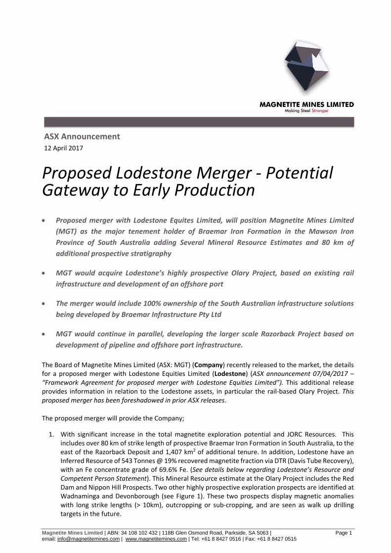
1. With significant increase in the total magnetite exploration potential and JORC Resources. This includes over 80 km of strike length of prospective Braemar Iron Formation in South Australia, to the east of the Razorback Deposit and 1,407 km2 of additional tenure. In addition, Lodestone have an Inferred Resource of 543 Tonnes @ 19% recovered magnetite fraction via DTR (Davis Tube Recovery), with an Fe concentrate grade of 69.6% Fe. (See details below regarding Lodestone’s Resource and Competent Person Statement). This Mineral Resource estimate at the Olary Project includes the Red Dam and Nippon Hill Prospects. Two other highly prospective exploration prospects are identified at Wadnaminga and Devonborough (see Figure 1). These two prospects display magnetic anomalies with long strike lengths (> 10km), outcropping or sub-cropping, and are seen as walk up drilling targets in the future.
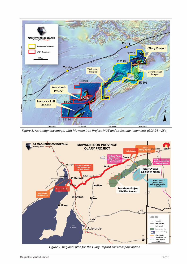
2. 100% ownership of Lodestones’ railway-based, Olary Project. A scoping study has been undertaken by Lodestone on the Red Dam Prospect, that examines the use of existing railway infrastructure and the idea for a deep water port north of Port Germein, Spencers Gulf, South Australia. Preliminary studies have indicated that the Olary Project has the potential of being developed more rapidly than the Razorback Project at a small to medium (start-up) scale, and then later expanded (see Figure 1 and 2). There is also potential access to water supply which is the key to the "start small and ramp up fast" approach. An important feature of the Olary Project will be the potential to produce Direct Reduction (DR) quality feed (69% Fe and above), which yields the highest price premium in the market. This high grade has been demonstrated in DTR analysis and preliminary metallurgical studies of drill sample completed by Lodestone. Further work will be required to qualify that these concentrate grades can be achieved at a larger scale. The Lodestone Scoping Study referred to in this release is based on low-level technical and economic assessments, and is insufficient to support estimation of Ore Reserves or to provide assurance of an economic development case at this stage, or to provide certainty that the conclusions of the Scoping Study will be realised.
3. Give the Company complete ownership of all infrastructure developments via 100% ownership of
Braemar Infrastructure Pty Ltd (BIPL). All the major and successful iron ore companies fully control their overland transport, their ports, and their shipping. BIBL is planning to develop at least two fully integrated transport solutions:
(1) The Olary Project would implement slurry pipeline transport from the Red Dam prospect to
a rail loading station at Olary. From the rail dumper 275 rail kilometres away north of Port Germein, the concentrate would be pumped as a slurry via an underwater pipeline to a proprietary offshore 250,000 dwt capable port for storage and dispatch to global steel makers (see Figure 2); and
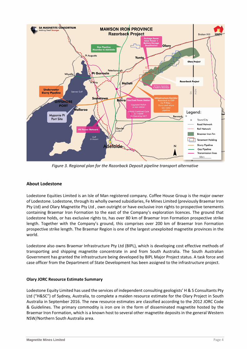
(2) The Razorback Project would use a slurry pipeline to transport magnetite concentrate from
mine directly to a proprietary offshore 400,000 dwt capable port north of Wallaroo for storage and dispatch to global steel makers (Figure 3). All pipeline systems would have a return water pipeline to minimise water usage or to make high quality water available for municipal, industrial and agricultural purposes. These BIPL infrastructure proposals have been given “Major Project” designation by the South Australian Government.
Previous studies by the Company in relation to the larger scale Razorback Project are continuing, although the Company’s focus in the immediate future will be on investigating the potential for a smaller scale start-up at the Olary Project. A significant advantage to the Company, is that a large part of the work completed at Razorback during the PFS and optimisation studies, is transferable and applicable to the Olary studies. The Board believe that if the Olary Project can be developed, then it may provide the Company with funding from cash flow to progress the Razorback Project and associated pipeline infrastructure development, as well as provide confidence in the market that developments in the Mawson Iron Province are economically viable ventures.
Magnetite Mines Limited Page 3
Figure 1. Aeromagnetic image, with Mawson Iron Project MGT and Lodestone tenements (GDA94 – Z54)
Figure 2. Regional plan for the Olary Deposit rail transport option
Magnetite Mines Limited Page 4
Figure 3. Regional plan for the Razorback Deposit pipeline transport alternative
About Lodestone
Lodestone Equities Limited is an Isle of Man registered company. Coffee House Group is the major owner of Lodestone. Lodestone, through its wholly owned subsidiaries, Fe Mines Limited (previously Braemar Iron Pty Ltd) and Olary Magnetite Pty Ltd , own outright or have exclusive iron rights to prospective tenements containing Braemar Iron Formation to the east of the Company’s exploration licences. The ground that Lodestone holds, or has exclusive rights to, has over 80 km of Braemar Iron Formation prospective strike length. Together with the Company’s ground, this comprises over 200 km of Braemar Iron Formation prospective strike length. The Braemar Region is one of the largest unexploited magnetite provinces in the world. Lodestone also owns Braemar Infrastructure Pty Ltd (BIPL), which is developing cost effective methods of transporting and shipping magnetite concentrate in and from South Australia. The South Australian Government has granted the infrastructure being developed by BIPL Major Project status. A task force and case officer from the Department of State Development has been assigned to the infrastructure project.
Olary JORC Resource Estimate Summary Lodestone Equity Limited has used the services of independent consulting geologists’ H & S Consultants Pty Ltd (“H&SC”) of Sydney, Australia, to complete a maiden resource estimate for the Olary Project in South Australia in September 2016. The new resource estimates are classified according to the 2012 JORC Code & Guidelines. The primary commodity is iron ore in the form of disseminated magnetite hosted by the Braemar Iron Formation, which is a known host to several other magnetite deposits in the general Western NSW/Northern South Australia area.
Magnetite Mines Limited Page 5
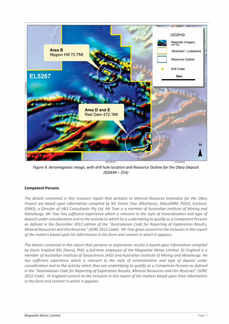
The Olary area under review was joint ventured by Lodestone with Helix Resources, but Lodestone now has full ownership of the property. The Olary Project deposits occurs within EL 5267, covering an area of 259 km2 and located approximately 150km south-west of Broken Hill. The area is divided into northern (Nippon Hill area) and southern zones (Red Dam area) with prospects AREA B in the former and prospects AREA D and AREA E in the latter. The Olary Project is located at the eastern end of the Adelaidian Fold-Belt, within the Olary Province. The ‘ironstone’ rocks of the Braemar Formation occur as a stratigraphic package of magnetite-rich siltstone associated with diamictite within the lower Umberatana Group. Typically, the magnetite is disseminated in fresh rock with no obvious structural stretching. The magnetite intensity is bed controlled linked to certain grain sizes and sediment composition i.e. a function of the sedimentary regime rather than any obvious structural overprint. There has been no previous exploration for magnetite in the licence areas. The maiden resource estimates are based on previous diamond and RC drilling completed by Helix Resources Ltd in 2011 to 2013. This comprised 57 holes for 10,751m of RC drilling and 987m of diamond drilling. Drill hole spacing is nominally 300 to 400m along strike and 100 to 150m down dip. Lodestone has supplied the drillhole database for the deposit to H&SC who have performed limited validation of the data including error checking, and completed some data processing to improve the database and enable easier geological interpretation. H&SC have accepted the drillhole database as satisfactory for resource estimation purposes. Density data was derived from the downhole geophysics which comprises a density measurement every centimetre. Lodestone completed a series of 75 check density measurements on core samples from one drillhole which showed an overall average difference of <0.4% with the corresponding geophysically-derived measurements. H&SC has also completed a set of geological interpretations for the areas that were drilled by Helix. The wireframes were based on a cross sectional review of the drilling combining logging codes including oxidation levels, the topographic surface, Davis Tube Recovery assays (“DTR”) at a nominal 5% DTR cut-off, and downhole geophysics. The work has also utilised geophysical modelling of airborne magnetic data, completed by Graeme Mackee of GeoDiscovery, to guide the structural interpretation of the host sediments. The wireframes were used to select a total of 1,132 with 4m composites for subsequent modelling using the Ordinary Kriging (“OK”) method with unfolding techniques. Downhole geophysical logs were also composited to the same interval length and subsequently modelled. Variogram models were created for AREA B and AREA D for DTR and concentrate grades for Fe, SiO2, Al2O3, P, S, and LOI as well as for the downhole probe data of gamma, magnetic susceptibility and density data. The AREA D variogram models were also used with modelling for AREA E (as shown in figure 4). Grade interpolation was undertaken using the Micromine software with the mineralised wireframes acting as hard boundaries. AREA E comprised an additional high grade domain which was used to control the grade interpolation. The resource model was then loaded into a Surpac block model for resource reporting and possible subsequent mine planning studies. Block sizes were generally 100m in the strike (X) direction, a function of the drill spacing, with a range of 10-50m in the Y direction and 10-20m in the Z direction, the latter two ranges took into account the geometry of the mineralisation and the likely open pit mining method. For AREA B and AREA D, a three pass search strategy was applied to estimate the volumes using the composite data for each element; for AREA E a fourth pass was added to enable a majority of the blocks inside the wireframe to have an interpolated grade. Search distances initially were 300m (strike) by 150m (down dip) by 20m (across strike) increasing to 450m by 225m by 40m. Minimum number of data was initially 16 decreasing to 8 for Passes 1 to 3 with the Pass 4 search in AREA E using the same maximum distances but this time using a minimum number of 4 data.
Magnetite Mines Limited Page 6
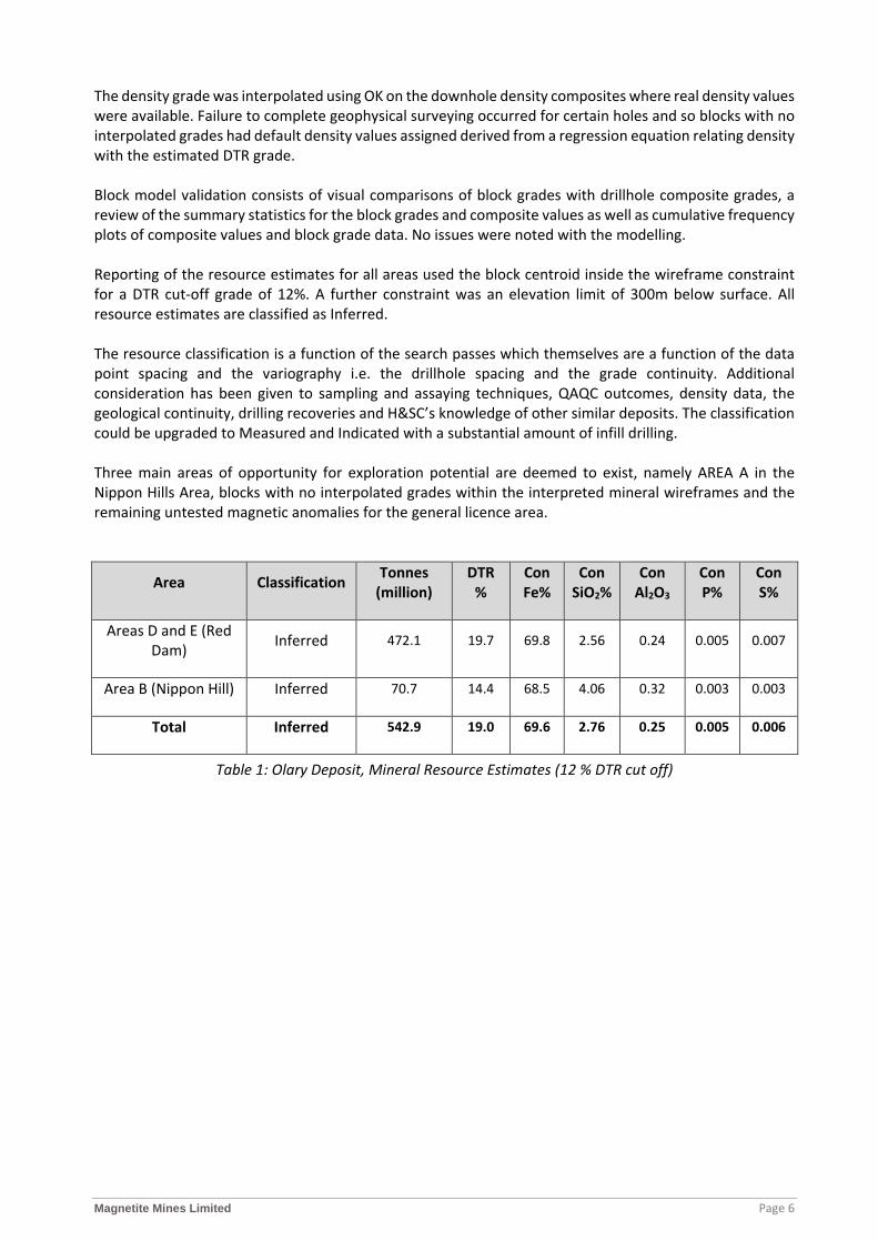
The density grade was interpolated using OK on the downhole density composites where real density values were available. Failure to complete geophysical surveying occurred for certain holes and so blocks with no interpolated grades had default density values assigned derived from a regression equation relating density with the estimated DTR grade. Block model validation consists of visual comparisons of block grades with drillhole composite grades, a review of the summary statistics for the block grades and composite values as well as cumulative frequency plots of composite values and block grade data. No issues were noted with the modelling. Reporting of the resource estimates for all areas used the block centroid inside the wireframe constraint for a DTR cut-off grade of 12%. A further constraint was an elevation limit of 300m below surface. All resource estimates are classified as Inferred.
The resource classification is a function of the search passes which themselves are a function of the data point spacing and the variography i.e. the drillhole spacing and the grade continuity. Additional consideration has been given to sampling and assaying techniques, QAQC outcomes, density data, the geological continuity, drilling recoveries and H&SC’s knowledge of other similar deposits. The classification could be upgraded to Measured and Indicated with a substantial amount of infill drilling. Three main areas of opportunity for exploration potential are deemed to exist, namely AREA A in the Nippon Hills Area, blocks with no interpolated grades within the interpreted mineral wireframes and the remaining untested magnetic anomalies for the general licence area.
Area Classification Tonnes (million)
DTR %
Con Fe%
Con SiO2%
Con Al2O3
Con P%
Con S%
Areas D and E (Red Dam) Inferred 472.1 19.7 69.8 2.56 0.24 0.005 0.007
Area B (Nippon Hill) Inferred 70.7 14.4 68.5 4.06 0.32 0.003 0.003
Total Inferred 542.9 19.0 69.6 2.76 0.25 0.005 0.006
Table 1: Olary Deposit, Mineral Resource Estimates (12 % DTR cut off)
Magnetite Mines Limited Page 7
Figure 4. Aeromagnetic image, with drill hole location and Resource Outline for the Olary Deposit
(GDA94 – Z54)
Competent Persons
The details contained in this resource report that pertains to Mineral Resource Estimates for the Olary Project are based upon information compiled by Mr Simon Tear (BSc(Hons), MAusIMM, PGEO, EurGeol, IOM3), a Director of H&S Consultants Pty Ltd. Mr Tear is a member of Australian Institute of Mining and Metallurgy. Mr Tear has sufficient experience which is relevant to the style of mineralisation and type of deposit under consideration and to the activity to which he is undertaking to qualify as a Competent Persons as defined in the December 2012 edition of the “Australasian Code for Reporting of Exploration Results, Mineral Resources and Ore Reserves” (JORC 2012 Code). Mr Tear gives consent to the inclusion in this report of the matters based upon his information in the form and context in which it appears.
The details contained in this report that pertains to exploration results is based upon information compiled by Gavin England BSc (Hons), PhD, a full-time employee of the Magnetite Mines Limited. Dr England is a member of Australian Institute of Geosciences (AIG) and Australian Institute of Mining and Metallurgy. He has sufficient experience which is relevant to the style of mineralisation and type of deposit under consideration and to the activity which they are undertaking to qualify as a Competent Persons as defined in the “Australasian Code for Reporting of Exploration Results, Mineral Resources and Ore Reserves” (JORC 2012 Code). Dr England consent to the inclusion in this report of the matters based upon their information in the form and context in which it appears.
Magnetite Mines Limited Page 8
The details contained in this report that pertains to ore and mineralisation and the resource for the Razorback Project and Ironback Hill Deposit is based upon information compiled by Gavin England BSc (Hons), PhD, a full-time employee of the Magnetite Mines Limited and Mr Lynn Widenbar BSc(Hons), MSc, DIC, Principal Consultant Widenbar and Associates Pty Ltd. Dr England and Mr Widenbar are members of Australian Institute of Geosciences (AIG) and Australian Institute of Mining and Metallurgy. These two people have sufficient experience which is relevant to the style of mineralisation and type of deposit under consideration and to the activity which they are undertaking to qualify as a Competent Persons as defined in the December 2004 edition of the “Australasian Code for Reporting of Exploration Results, Mineral Resources and Ore Reserves” (JORC 2004 Code), as well as the current JORC 2012 Code. Dr England, and Mr Widenbar consent to the inclusion in this report of the matters based upon their information in the form and context in which it appears. The information for the Razorback Deposit was prepared and first disclosed under the JORC Code 2004. The information has not been updated since to comply with the JORC Code 2012 on the basis that the information has not materially changed since it was last reported.
For further information, contact: Gordon Toll Peter Schubert Chairman and Chief Executive Officer Executive Director +61 8 8427 0516 +61 416 375 346
Section 1 Sampling Techniques and Data
Criteria JORC Code explanation Commentary
Sampling
techniques
Nature and quality of sampling (e.g. cut channels, random chips, or specific specialised industry standard measurement tools appropriate to the minerals under investigation, such as down hole gamma sondes, or handheld XRF instruments, etc). These examples should not be taken as limiting the broad meaning of sampling.
Include reference to measures taken to ensure sample representivity and the appropriate calibration of any measurement tools or systems used.
Aspects of the determination of mineralisation that are Material to the Public Report.
In cases where ‘industry standard’ work has been done this would be relatively simple (e.g. ‘reverse circulation drilling was used to obtain 1 m samples from which 3 kg was pulverised to produce a 30 g charge for fire assay’). In other cases more explanation may be required, such as where there is coarse gold that has inherent sampling problems. Unusual commodities or mineralisation types (e.g. submarine nodules) may warrant disclosure of detailed information.
A total of 57 holes were drilled in the Olary Magnetite Project, of
which 34 were then used to estimate an Inferred Mineral
Resource. Phase 1 drilling occurred in July 2011 consisting of
1,534 m of RC drilling. Phase 2 during later 2012 – early 2013
consisted of approximately 11,000 m RC and 1000 diamond core
drilling.
Reverse Circulation (RC) drilling obtain individual metre
samples collected in green plastic bags. Sampling consisted of a
geologist and/or field assistant sampling individual metres for
assay determination (generally collecting 3 kg sample which was
pulverized to produce 500 g aliquot for XRF determination),
taking magnetic susceptibility measurements, and geologic
logging completed on every drillhole.
Diamond core drillholes (DD), all with RC pre-collars had
sampling process involving: clean and photograph the core,
grain size), record magnetic susceptibility, density determination
(Archimedes method and bulk tray method), mark the
mineralised zones for sampling, cut the core, and sample.
GAA Wireline carried out down hole geophysical logging and
gyroscopic hole deviation surveying on all drillholes in the
second phase of drilling. Surveys were conducted open hole. In
the first phase of drilling, down hole deviation reverted to down
hole camera, or in the absence of that a clinometer and compass
reading was taken at the collar. The geophysical logging
Making Steel Stronger
MAGNETITE MINES LIMITED
1 H SC&
2012 JORC Code & Guidelines - Table 1
2012 JORC Code & Guidelines - Table 1 Olary Project
Criteria JORC Code explanation Commentary
consisted of natural gamma, magnetic susceptibility, density,
resistivity and calliper readings.
MM has a suite of documented procedures for drilling related
activities
Consistency of sampling method maintained.
Sampling technique is considered appropriate for deposit type
Drilling
techniques
Drill type (e.g. core, reverse circulation, open-hole hammer, rotary air blast, auger, Bangka, sonic, etc.) and details (e.g. core diameter, triple or standard tube, depth of diamond tails, face-sampling bit or other type, whether core is oriented and if so, by what method, etc.).
Drilling was a combination of RC and DD
Industry standard drilling rigs suitable for the required task
were used.
RC drilling was carried out using a Me�ke RC rig on an 8x4
carrier with auxiliary compressor (350psi/900cfm) and Arial
Booster (900psi) on a separate carrier. It used a 5 ½ inch face
sampling hammer on 4 inch drill rods.
DD drilling carried out using a UDR650, with NQ and HQ
diameter triple tube.
Drill sample
recovery
Method of recording and assessing core and chip sample recoveries and results assessed.
Measures taken to maximise sample recovery and ensure representative nature of the samples.
Whether a relationship exists between sample recovery and grade and whether sample bias may have occurred due to preferential loss/gain of fine/coarse material.
Sample recoveries for RC drilling were estimated by the field
technicians at the time of drilling and recorded in the field
sampling sheets.
Sample recoveries for DD were recorded by field technicians
after measuring the length of core recovered divided by the
length of each individual core run; expressed in metres in the
“Recovery_Diff” field, and as a percentage in the “Recovery pct”
field. Core loss is noted in a comments column when
encountered.
No studies were undertaken to specifically examine possible
biases.
Logging Whether core and chip samples have been geologically and geotechnically logged to a level of detail to support appropriate Mineral Resource estimation, mining studies and metallurgical studies.
Every RC and DD drillhole was geologically logged on paper
and then entered into an excel spreadsheet. Fields recorded
include - colour, weathering, regolith, lithology, grain size,
Making Steel StrongerMAGNETITE MINES LIMITED
2 H SC&
2012 JORC Code & Guidelines - Table 1
Criteria JORC Code explanation Commentary
Whether logging is qualitative or quantitative in nature. Core (or costean, channel, etc) photography.
The total length and percentage of the relevant intersections logged.
foliation, texture, min%, min. style, alteration, alteration
and description being recorded. Data was uploaded to a
customised Access database
Logging used a mixture of qualitative and quantitative codes
A sample of sieved wet chips from all RC holes were collected
into chip trays every metre for every hole.
All un-sampled diamond core was retained in core trays at
MM’s core storage facility in Adelaide
Once a DD hole had been orientated, metre marked, magnetic
susceptibility recorded, and the geologist has finished logging,
the core was photographed starting from tray one through to the
last tray.
All drill core was photographed wet and dry after logging but
before cu�ing.
All relevant intersections were logged
Geological logging was of sufficient detail to allow the creation
of a geological model to support stated resource classification.
Sub-sampling
techniques and
sample
preparation
If core, whether cut or sawn and whether quarter, half or all core taken.
If non-core, whether riffled, tube sampled, rotary split, etc and whether sampled wet or dry.
For all sample types, the nature, quality and appropriateness of the sample preparation technique.
Quality control procedures adopted for all sub-sampling stages to maximise representivity of samples.
Measures taken to ensure that the sampling is representative of the in situ material collected, including for instance results for field duplicate/second-half sampling.
Whether sample sizes are appropriate to the grain size of the material being sampled.
RC drill rigs were fi�ed with either a riffle spli�er (dry) or cone
spli�er (minor moist samples) which produced a 3–5 kg sub-
sample for every metre drilled. This subsample was collected in
plastic bags at the drill rig. The spli�ers were cleaned when
necessary as the hole progressed and cleaned thoroughly at the
end of each hole.
The 1 metre splits passed through a 25/75 riffle spli�er to
produce a 4m composite sample of >2kg minimum ideal weight
(spring scales). Material passed through spli�er for several
passes to obtain composite weight of >2kg with optimal
composite sample weight ~4kg. The end of hole composites may
vary in length.
Four metre RC composite is then tested with a magnetic
Making Steel StrongerMAGNETITE MINES LIMITED
3 H SC&
2012 JORC Code & Guidelines - Table 1
Criteria JORC Code explanation Commentary
susceptibility metre to determine if samples are sent on for DTR
analysis
As a quality control measure for RC samples, the field
technicians recorded sample conditions.
For DD, sampling intervals selected on the basis of logged
lithology and single point KT9 magnetic susceptibility values for
each metre averaged over 4m with readings >10 x 10-3 SI plus
buffer of 4 composites (16m).
DD core was sampled by sawing in half lengthways. One
quarter of the core was submi�ed to the laboratory for head
grade determination (and some for Davis Tube Recovery(DTR))
with the remaining half retained in core trays. Samples were
submi�ed as a 4 metre composite.
The sampling methods and sample sizes are considered to be
generally in accordance with common industry practice.
Samples sent to ALS Adelaide were crushed to <3.35mm, slit to
~2kg using Jones Riffle Spli�er, homogenise sample via rolling
mat and selectively sub-sample a 150g sample.
Sample measured using laboratory magnetic susceptibility meter
(SATMAGAN) and expected DTR recorded by comparison
against ALS in-house magnetite calibration curve.
Samples of predicted >/=5% DTR from magnetic susceptibility
selected for DTR analysis.
Samples of <5%predicted DTR retained at ALS Adelaide
DTR samples freighted by ALS Pooraka, SA to ALS Wangara,
WA for DTR analysis
Field duplicates, blanks (river sand) and certified standards we
used for quality control measures
All sampling methods and samples sizes are deemed
appropriate
Quality of The nature, quality and appropriateness of the assaying and DTR and XRF analysis was completed at ALS Adelaide, using
Making Steel StrongerMAGNETITE MINES LIMITED
4 H SC&
2012 JORC Code & Guidelines - Table 1
Criteria JORC Code explanation Commentary
assay data and
laboratory tests
laboratory procedures used and whether the technique is considered partial or total.
For geophysical tools, spectrometers, handheld XRF instruments, etc, the parameters used in determining the analysis including instrument make and model, reading times, calibrations factors applied and their derivation, etc.
Nature of quality control procedures adopted (e.g. standards, blanks, duplicates, external laboratory checks) and whether acceptable levels of accuracy (i.e. lack of bias) and precision have been established.
standard industry techniques. The DTR process is described
below:
Pulverizing
o Crush the sample to 100% below 3.35mm
o Separate a sample of 150gm for pulverizing in a C125
ring pulveriser (record weight) – DTR SAMPLE
o For soft ferro-silicate rocks - initially pulverize the
150gm sample for 60 seconds
o Wet screen the DTR sample at XX (38, 45, 75 etc) micron
and dry the products.
o Record the oversize weights – if less than approximately
20gm is oversize, stop the procedure – failure.
o If failure - select another 150 gm DTR Sample and
reduce the initial pulverization time by 5 secs, repeat
until initial grind pass returns greater than
approximately 20 gm oversize. Once achieved retain the
– XX micron undersize.
o Regrind only the oversize for 1 second for every 5 gms
of oversize sample weight
o Repeat the wet screening, drying and weighing stages
until less than 5gm above 45 micron remains.
o Ensure the remaining < 5gm oversize is returned back
into the previously retained -45 micron undersize.
o Report the times and weights for each grind pass phase.
o Combine and homogenize all retained -XX micron
aliquots and <5gm oversize, pressure filter and dry,
break up and de-lump dried material with 1mm sieve
and dry rehomogenise - final pulverized product
o Sub-sample the final pulverized product to give a 20gm
feed sample for DTR work and a ~10g sample for HEAD
Making Steel StrongerMAGNETITE MINES LIMITED
5 H SC&
2012 JORC Code & Guidelines - Table 1
Criteria JORC Code explanation Commentary
analysis via XRF or ICP fusion.
o The objective of the pulverizing procedure is to achieve
a nominal P80 of approximately 70% of 45 micron
screen.
Davis Tube Recovery (DTR) Analysis
The nominal procedure has the following condition:
o Pulveriser bowl 150 ml
o Stroke Frequency 60/minute
o Stroke length – 38mm
o Magnetic field strength – 3000 gauss
o Tube Angle – 45 degrees
o Tube Diameter – 40mm
o Water flow rate – 540-590 ml/min
o Washing time 20 minutes
o Collect the concentrate in small collector (magnetic
fraction) and discard tails.
Assaying (usually XRF Fusion)
Head Sample
o Using the Head Sample, analyse by XRF or method
for the following elements: Al2O3 %, As % , Ba % ,
CaO % , Cl % , Co % , Cr % , Cu % , Fe % , K2O % ,
MgO % , Mn % , Na2O % , Ni % , P % , Pb % , S % ,
SiO2 % , Sn % , Sr % , TiO2 % , V % , Zn % , Zr % &
LOI.
Making Steel StrongerMAGNETITE MINES LIMITED
6 H SC&
2012 JORC Code & Guidelines - Table 1
Criteria JORC Code explanation Commentary
DTR Concentrate Sample
o Dry the DTR concentrate and report the weight of the
concentrate as a percentage of measured feed and
report – DTR Mass Recovery.
o Analyse concentrate by XRF or ICP fusion method for
the following elements: Al2O3 %, As %, Ba % , CaO
% , Cl % , Co % , Cr % , Cu % , Fe % , K2O % , MgO %
, Mn % , Na2O % , Ni % , P % , Pb % , S % , SiO2 % ,
Sn % , Sr % , TiO2 % , V % , Zn % , Zr % & LOI
No certified standards, blanks, umpire lab samples or field
resamples were undertaken during or after drilling occurred.
QAQC included limited field and laboratory duplicates.
Internal QAQC measures were also undertaken by ALS.
Specific gravity (SG) was measured on representative diamond
core samples using the displacement method.
All sampling and assay methods and samples sizes are deemed
appropriate.
Verification of
sampling and
assaying
The verification of significant intersections by either independent or alternative company personnel.
The use of twinned holes. Documentation of primary data, data entry procedures, data
verification, data storage (physical and electronic) protocols. Discuss any adjustment to assay data.
No twinned holes were drilled
Data is stored in an Access database stored in the Adelaide
Office and a backup version in an external location. Data was
originally stored in the Helix Resources server when project was
still in the company’s control.
For data verification, all sample results were checked and
verified against core logging and photography by Braemar Iron
personnel post Helix Resources drilling. In addition, Braemar
staff reviewed the sample data and assay results.
No adjustments or ‘factors’ were applied to raw assay data
Making Steel StrongerMAGNETITE MINES LIMITED
7 H SC&
2012 JORC Code & Guidelines - Table 1
Criteria JORC Code explanation Commentary
Location of
data points
Accuracy and quality of surveys used to locate drill holes (collar and down-hole surveys), trenches, mine workings and other locations used in Mineral Resource estimation.
Specification of the grid system used. Quality and adequacy of topographic control.
Drillhole coordinates were picked up by contractors GAA
Wireline and Helix Resources using DGPS. Coordinates were
supplied in GDA94 - MGA Zone 54.
Topographic control was by a Digital Terrain Model (DTM)
provided by geophysical contractors with the results of close
spaced, fixed wing magnetic and radiometric survey and DGPS.
The DTM was modified around drill collar positions to reflect
the greater accuracy of topographic control in these areas.
Down hole surveys were recorded using a gyroscope due to the
highly magnetic nature of the deposit.
Location methods used to determine accuracy of drillhole collars
are considered appropriate
Data spacing
and
distribution
Data spacing for reporting of Exploration Results. Whether the data spacing and distribution is sufficient to establish the
degree of geological and grade continuity appropriate for the Mineral Resource and Ore Reserve estimation procedure(s) and classifications applied.
Whether sample compositing has been applied.
The deposit is drilled approximately 400 m x 100 m spacing
(between section and on section respectively).
The interpreted continuity and classification of the reported
resource takes the drill spacing into account, relative to the style
of mineralisation in question.
Samples were composited for submission for assay to 4 metres.
Orientation of
data in relation
to geological
structure
Whether the orientation of sampling achieves unbiased sampling of possible structures and the extent to which this is known, considering the deposit type.
If the relationship between the drilling orientation and the orientation of key mineralised structures is considered to have introduced a sampling bias, this should be assessed and reported if material.
Drilling (sampling) was completed with best knowledge of
geology, heavily influenced by interpretation from 3D modelling
of aeromagnetic data. This is considered appropriate to gather
representative samples from an orebody.
Drilling was completed at -60o, generally sub-perpendicular to
the bedding, which is the primary control to the magnetite
mineralisation.
Different azimuths were used to reflect the changing strike of the
beds associated with folding of the sediments and were
designed to maintain the steep angle to the bedding
Drilling orientations are considered appropriate with no bias.
Sample The measures taken to ensure sample security. As RC hole is drilled the plastic bag assay samples are collected
Making Steel StrongerMAGNETITE MINES LIMITED
8 H SC&
2012 JORC Code & Guidelines - Table 1
Criteria JORC Code explanation Commentary
security into large green or polyweave bags three at a time and are
fastened at the top with cable ties and left in sequence for
collection or put directly onto a vehicle and transported back to
the sample facility on site.
DD samples, once marked up by a geologist or field assistant,
are cut and collected in calico bags and placed in clearly labelled
large plastic bags (or similar) and are stored at the sample
facility on site.
Samples were transported by Helix staff from site to a freight
forwarding company in Broken Hill which forwarded them to
ALS Perth, via ALS Adelaide in sealed ‘Bulka Bags’. Upon
receipt of the samples the laboratory would check the sample
dispatch form with the consignment received and advise of any
missing/damaged samples
Audits or
reviews
The results of any audits or reviews of sampling techniques and data. No external audits have been completed.
The QAQC data was reviewed by Lodestone staff
Section 2 Reporting of Exploration Results
(Criteria listed in the preceding section also apply to this section.)
Criteria JORC Code explanation Commentary
Mineral
tenement and
land tenure
status
Type, reference name/number, location and ownership including agreements or material issues with third parties such as joint ventures, partnerships, overriding royalties, native title interests, historical sites, wilderness or national park and environmental settings.
The security of the tenure held at the time of reporting along with any known impediments to obtaining a licence to operate in the area.
Olary tenement EL5267 is granted and owned by Olary
Magnetite Pty Ltd (subsidiary of Lodestone Equities Pty Ltd).
The tenement is located approximately 150 km Southwest of
Broken Hill, on the Olary 1:250,000 sheet.
EL5267 is situated on the Maldorky Pastoral Lease
The area is subject to a Native Title Claim by the Wilyakali
Group. Olary Magnetite have a native title agreement with the
Wilyakali for access.
Making Steel StrongerMAGNETITE MINES LIMITED
9 H SC&
2012 JORC Code & Guidelines - Table 1
Criteria JORC Code explanation Commentary
There are no national parks or conservation reserves within the
tenement area.
EL5267 is subject to a 1% royalty (FOB) to the previous owners
of the tenement.
Exploration
done by other
parties
Acknowledgment and appraisal of exploration by other parties. All drilling relating to this resource was performed by Helix
Resources Ltd.
Geology Deposit type, geological setting and style of mineralisation. The Olary Magnetite Project is located at the eastern end of the
Adelaidian Fold-Belt, within the Olary Province. The ‘ironstone’
rocks of the Braemar Formation occur as a stratigraphic package
of magnetite-rich siltstone associated with diamictite within the
lower Umberatana Group.
The Braemar Formation comprises a series of narrow, strike
extensive magnetite-bearing siltstones generally that have been
substantially deformed.
The airborne magnetic data clearly indicates the magnetite
siltstones as a series of narrow, high amplitude magnetic
anomalies. Geophysical forward modelling has generated
insight to the structural deformation including isoclinal and
recumbent folding
Large areas of the prospective stratigraphy are concealed by
transported ferricrete and other younger cover. The base of
oxidation due to weathering over the prospective horizons is
variable with estimates up to 80m from surface.
Typically, the magnetite is disseminated in fresh rock with no
obvious structural stretching. The magnetite intensity is bed
controlled linked to certain grain sizes and sediment
composition i.e. a function of the sedimentary regime rather than
any obvious structural overprint.
The Olary project comprises a number of prospects. Resource
Making Steel StrongerMAGNETITE MINES LIMITED
10 H SC&
2012 JORC Code & Guidelines - Table 1
Criteria JORC Code explanation Commentary
Estimates have been generated for AREA B, AREA D and AREA
E; the last two are interpreted to be contiguous. AREA A has an
ambiguous geological interpretation which resulted in no
resource estimates being generated.
The depositional environment for the Braemar Iron Formation is
believed to be a subsiding basin, with initial rapid subsidence
related to rifting possibly in a graben se�ing as indicated by. the
occurrence of diamictites in the lower part of the sequence. A
possible sag phase of cyclical subsidence followed with
deposition of finer grained sediments with more consistent, as
compared to the diamictite units, bed thicknesses, style and clast
composition.
The Olary prospects are similar to other resources in the
Braemar Ironstone eg Hawsons and Muster Dam.
Drill hole
Information
A summary of all information material to the understanding of the exploration results including a tabulation of the following information for all Material drill holes: o easting and northing of the drill hole collar o elevation or RL (Reduced Level – elevation above sea level in
metres) of the drill hole collar o dip and azimuth of the hole o down hole length and interception depth o hole length.
If the exclusion of this information is justified on the basis that the information is not Material and this exclusion does not detract from the understanding of the report, the Competent Person should clearly explain why this is the case.
Exploration results not being reported
Data
aggregation
methods
In reporting Exploration Results, weighting averaging techniques, maximum and/or minimum grade truncations (e.g. cutting of high grades) and cut-off grades are usually Material and should be stated.
Where aggregate intercepts incorporate short lengths of high grade results and longer lengths of low grade results, the procedure used for such aggregation should be stated and some typical examples of
Exploration results not being reported
Making Steel StrongerMAGNETITE MINES LIMITED
11 H SC&
2012 JORC Code & Guidelines - Table 1
Criteria JORC Code explanation Commentary
such aggregations should be shown in detail. The assumptions used for any reporting of metal equivalent values
should be clearly stated.
Relationship
between
mineralisation
widths and
intercept
lengths
These relationships are particularly important in the reporting of Exploration Results.
If the geometry of the mineralisation with respect to the drill hole angle is known, its nature should be reported.
If it is not known and only the down hole lengths are reported, there should be a clear statement to this effect (e.g. ‘down hole length, true width not known’).
Drilling has tended to be at a steep angle to the dip angle of the
sedimentary beds.
Diagrams Appropriate maps and sections (with scales) and tabulations of intercepts should be included for any significant discovery being reported These should include, but not be limited to a plan view of drill hole collar locations and appropriate sectional views.
Exploration results not being reported
Balanced
reporting
Where comprehensive reporting of all Exploration Results is not practicable, representative reporting of both low and high grades and/or widths should be practiced to avoid misleading reporting of Exploration Results.
Exploration results not being reported
Other
substantive
exploration
data
Other exploration data, if meaningful and material, should be reported including (but not limited to): geological observations; geophysical survey results; geochemical survey results; bulk samples – size and method of treatment; metallurgical test results; bulk density, groundwater, geotechnical and rock characteristics; potential deleterious or contaminating substances.
The area is covered by a detailed government generated airborne
magnetic survey
Downhole geophysics comprises magnetic susceptibility,
gamma and density and has been completed for a majority of the
holes. This has resulted in the definition of a magnetic (and
density-related) stratigraphy
Further work The nature and scale of planned further work (e.g. tests for lateral extensions or depth extensions or large-scale step-out drilling).
Diagrams clearly highlighting the areas of possible extensions, including the main geological interpretations and future drilling areas, provided this information is not commercially sensitive.
Exploration results not being reported
Making Steel StrongerMAGNETITE MINES LIMITED
12 H SC&
2012 JORC Code & Guidelines - Table 1
Section 3 Estimation and Reporting of Mineral Resources
(Criteria listed in section 1, and where relevant in section 2, also apply to this section.)
Criteria JORC Code explanation Commentary
Database
integrity
Measures taken to ensure that data has not been corrupted by, for example,
transcription or keying errors, between its initial collection and its use for
Mineral Resource estimation purposes.
Data validation procedures used.
Independently customised Access database was complied by
Helix Resources while they were managers of the project.
Validation of database was undertaken by Lodestone Equity in
2016. The data was found to be of a sound nature suitable to
produce an Inferred Resource.
Limited validation was conducted by H&S Consultants (H&SC)
to ensure the drill hole database is internally consistent.
Validation included checking that no assays, density
measurements or geological logs occur beyond the end of hole
and that all drilled intervals have been geologically logged. The
minimum and maximum values of assays and density
measurements were checked to ensure values are within
expected ranges. Further checks include testing for duplicate
samples and overlapping sampling or logging intervals
H&SC has not performed detailed database validation and
Lodestone Equity personnel take responsibility for the accuracy
and reliability of the data used to estimate the Mineral
Resources.
Data was loaded by H&SC into an Access database for use with
the Surpac mining software to complete 3D visualisation,
geological interpretation and resource reporting.
Site visits Comment on any site visits undertaken by the Competent Person and the
outcome of those visits.
If no site visits have been undertaken indicate why this is the case.
The drilling project was undertaken by Helix Resources as
managers of the project. This was later reviewed by Gavin
England in 2015 and 2016, who acts as the Competent Person
with responsibility for reporting the exploration results and the
integrity and validity of the database on which resource
estimates were conducted.
Making Steel StrongerMAGNETITE MINES LIMITED
13 H SC&
2012 JORC Code & Guidelines - Table 1
Criteria JORC Code explanation Commentary
The two faults are possibly a conjugate pair, and have caused
offsets in the mineral-bearing stratigraphy.
H&SC created a series of wireframes representing the outlines of
individual magnetite-rich lithological units based on drill hole
data. These wireframes were treated as hard boundaries during
estimation.
H&SC also used the geological logs of the drill holes to create
wireframe surfaces representing the base of colluvium, the base
of complete oxidation and the top of fresh rock.
Any additional faulting in the deposit is assumed to be
insignificant on the scale important to resource estimation.
H&SC is aware that alternative interpretations of the mineralised
zones and fault are possible but consider the wireframes to
adequately approximate the locations of the mineralised zones
for the purposes of resource estimation. Alternative
interpretations may have a limited impact the resource estimate.
Dimensions The extent and variability of the Mineral Resource expressed as length
(along strike or otherwise), plan width, and depth below surface to the upper
and lower limits of the Mineral Resource.
The resources reported here are from three discrete areas that lie
in a rectangle around 15km long and 4.5km wide.
The mineralisation at AREA A has a strike length of around
2.1km in an east south easterly direction. The plan width of the
mineralisation varies from 140m to 420m with an average of
around 320m. The upper limit of the mineralisation occurs at a
depth of 4m below surface and the lower limit of the reported
resource is limited to a depth of 300m below surface.
The resources at AREA B have a strike length of around 1.5km in
an east south easterly direction. The plan width of the resource
varies from 260m to 470m with an average of around 330m. The
upper limit of the mineralisation occurs at a depth of 4m below
surface and the lower limit of the reported resource is limited to
a depth of 300m below surface.
The resources at AREA D are split into two discrete areas that
Making Steel StrongerMAGNETITE MINES LIMITED
14 H SC&
2012 JORC Code & Guidelines - Table 1
Criteria JORC Code explanation Commentary
Gavin England has made several drill site visits from 2015 to
2016 and examined samples stored in Adelaide.
No site visit has been undertaken by H&SC due to time and
budgetary constraints
Geological
interpretation
Confidence in (or conversely, the uncertainty of) the geological
interpretation of the mineral deposit.
Nature of the data used and of any assumptions made.
The effect, if any, of alternative interpretations on Mineral Resource
estimation.
The use of geology in guiding and controlling Mineral Resource estimation.
The factors affecting continuity both of grade and geology.
The magnetite mineralisation is stratabound as opposed to
stratiform.
The downhole geophysical data has been used in conjunction
with DTR recovered magnetic fraction grades and geological
logging to allow for the generation of a set of 3D wireframes
representing the mineral units and some cursory geological
controls.
The lithological interpretations are therefore relatively simple
and reasonably well constrained by the drilling and the high
amplitude magnetic anomalies.
AREA A is interpreted to consist of two layers of magnetite-rich
zones and is considered to be a more complex area for geological
understanding. This is mainly because it is in an area of
diamictite dominant sediments with an associated level
discordancy linked to the sediment deposition.
AREA B is also interpreted to consist of two magnetite-rich
layers that dip around 25° towards 205°.
AREA E comprises an anticline associated with an isoclinal fold
with the E-W hinge line roughly sub-horizontal. The southern
limb dips almost vertical whilst the northern limb dips at a
slightly shallower angle to the north.
AREA D is more complex in that the isoclinal folding has
become more recumbent. AREA E and AREA D are believed to
be the same body of mineralisation separated by a combination
of a NW-SE and an E-W cross-cu�ing faults. At this stage the
faults have been used to limit the extent of the mineralisation by
providing lateral control to interpreting the mineral wireframes.
Making Steel StrongerMAGNETITE MINES LIMITED
15 H SC&
2012 JORC Code & Guidelines - Table 1
Criteria JORC Code explanation Commentary
are interpreted to be linked at depth. Overall it has a strike
length of around 1.5km in a north-south direction. The plan
width of the resource varies from 300m to 700m with an average
of around 600m. The upper limit of the mineralisation occurs at a
depth of 4m below surface and the lower limit of the reported
resource is limited to a depth of 300m below surface.
The resources at AREA E have a strike length of around 2.2km in
an east-west direction. The plan width of the resource varies
from 400m to 530m. The upper limit of the mineralisation occurs
at a depth of 4m below surface and the lower limit of the
reported resource is limited to a depth of 300m below surface.
Estimation and
modelling
techniques
The nature and appropriateness of the estimation technique(s) applied and
key assumptions, including treatment of extreme grade values, domaining,
interpolation parameters and maximum distance of extrapolation from data
points. If a computer assisted estimation method was chosen include a
description of computer software and parameters used.
The availability of check estimates, previous estimates and/or mine
production records and whether the Mineral Resource estimate takes
appropriate account of such data.
The assumptions made regarding recovery of by-products.
Estimation of deleterious elements or other non-grade variables of economic
significance (e.g. sulphur for acid mine drainage characterisation).
In the case of block model interpolation, the block size in relation to the
average sample spacing and the search employed.
Any assumptions behind modelling of selective mining units.
Any assumptions about correlation between variables.
Description of how the geological interpretation was used to control the
resource estimates.
Discussion of basis for using or not using grade cu�ing or capping.
The process of validation, the checking process used, the comparison of model
The head iron, Davis Tube Recovery (DTR) and concentrate iron,
silica, alumina, phosphorous, sulphur and Loss on Ignition (LOI)
were estimated using Ordinary Kriging on 4m composites in the
Micromine software. H&SC considers Ordinary Kriging to be an
appropriate estimation technique for the type of mineralisation
and extent of data available from the deposits. All data have
low coefficients of variation.
Some intervals had no DTR values. A regression based on
Satmagan test work was used to calculate likely DTR values for
untested intervals. A regression based on the hand held
magnetic susceptibility data was used to estimate the DTR
values where Satmagan data was not available. Missing Fe
concentrate grades were calculated using a regression based on
the DTR grades and the remaining concentrate elements were
calculated using a regression based on the iron concentrate
grade. All of the missing DTR grades were from poorly
magnetic, low grade, intervals. The missing concentrate grades
were either the result of a lack of DTR test work or due to
insufficient sample being available for XRF due to low DTR
recovery.
Making Steel StrongerMAGNETITE MINES LIMITED
16 H SC&
2012 JORC Code & Guidelines - Table 1
Criteria JORC Code explanation Commentary
data to drill hole data, and use of reconciliation data if available. For AREA B and AREA D each of the mineral wireframes were
treated as hard boundaries so that only composite samples
inside the wireframe were used to estimate blocks within the
corresponding wireframe.
For AREA E the outer low grade zone was estimated using only
composite samples from within the outer low-grade zone
whereas the inner high grade zone was estimated using samples
from both the inner and outer mineralised zones. This approach
is considered to be conservative and more drilling is needed to
be�er constrain the high grade zone.
The geological interpretation of AREA D and AREA E indicate
significant folding has affected the mineralised lodes on a scale
that is the same or shorter than the drill hole spacing. H&SC
therefore used the unfolding technique available in Micromine
to unfold the block model and composite data relative to a
central wireframe surface.
The search ellipse and variography were rotated to be parallel to
the orientation of each of the mineralised domains. A flat search
was used to estimate the unfolded AREA D and AREA E.
No recovery of any by-products has been considered in the
resource estimates as no products beyond iron are considered to
exist in economic concentrations.
No top-cu�ing was applied as extreme values were not present
and top-cu�ing was considered by H&SC to be unnecessary
Several estimates were conducted to assess sensitivity to various
parameters however no check estimate was carried out by a
different estimator or technique.
The concentrations of deleterious silica, alumina, phosphorous
and sulphur in the magnetic concentrate were estimated.
Block dimensions for AREA E are 100m x 10m x 20m (Local E, N,
RL respectively) Whereas block dimensions for AREA B is 100m
Making Steel StrongerMAGNETITE MINES LIMITED
17 H SC&
2012 JORC Code & Guidelines - Table 1
Criteria JORC Code explanation Commentary
x 20m x 10m. Block dimensions for AREA D is 100m x 50m x
10m.
Each element was estimated separately. For AREA B and AREA
D a three pass search strategy was employed with progressively
larger radii and/or decreasing search criteria. In AREA E a fourth
pass was added in order to populate certain blocks, mainly in
the outer low grade zone, that had not been populated due to
the thin nature of the mineralised zone.
All passes used a four sector search ellipse in order to aid de-
clustering. The first pass used a search ellipse of 300x150x20m
(along strike, down dip and across mineralisation respectively)
and required a minimum of 16 composites from at least three
drill holes. The maximum total number of composites was set to
32 with a limit of eight per drill hole. The second pass criteria
were similar except the search ellipse was 450x225x40m and only
two drill holes were required. The third and fourth passes also
used a search ellipse measuring 450x225x40m but the minimum
number of composites required was set to eight and four
respectively and no restriction on the number of drill holes was
applied.
The H&SC block model was reviewed visually by H&SC and it
was concluded that the block model fairly represents the grades
observed in the drill holes. H&SC also validated the block model
using a variety of summary statistics and simple plots.
Moisture Whether the tonnages are estimated on a dry basis or with natural moisture,
and the method of determination of the moisture content.
Tonnages of the Mineral Resource are estimated on a dry weight
basis.
Cut-off
parameters
The basis of the adopted cut-off grade(s) or quality parameters applied. The resources are reported at a cut-off of 12% DTR within the
mineral wireframe which is consistent with the original
reporting of the Hawsons and Muster Dam deposits.
The estimated resources reported are limited to a vertical depth
Making Steel StrongerMAGNETITE MINES LIMITED
18 H SC&
2012 JORC Code & Guidelines - Table 1
Criteria JORC Code explanation Commentary
of 300m.
The cut-off grade at which the resource is quoted reflects the
intended bulk-mining approach
Mining factors
or assumptions
Assumptions made regarding possible mining methods, minimum mining
dimensions and internal (or, if applicable, external) mining dilution. It is
always necessary as part of the process of determining reasonable prospects
for eventual economic extraction to consider potential mining methods, but
the assumptions made regarding mining methods and parameters when
estimating Mineral Resources may not always be rigorous. Where this is the
case, this should be reported with an explanation of the basis of the mining
assumptions made.
The Olary resources were estimated on the assumption that the
material is to be mined by open pit using a bulk mining method.
Minimum mining dimensions are envisioned to be around 25m
x 10m x 10m (strike, across strike, vertical respectively). The
block size is significantly larger than the likely minimum mining
dimensions.
A conceptual study was completed in 2013, which examined
mining methods. Given the Resource is of an Inferred nature, the
parameters were not of a rigorous nature. The study found the
proposed mining method to be a fully mobile In-Pit Crushing
and Conveying, combined with shovel. .
Metallurgical
factors or
assumptions
The basis for assumptions or predictions regarding metallurgical
amenability. It is always necessary as part of the process of determining
reasonable prospects for eventual economic extraction to consider potential
metallurgical methods, but the assumptions regarding metallurgical
treatment processes and parameters made when reporting Mineral Resources
may not always be rigorous. Where this is the case, this should be reported
with an explanation of the basis of the metallurgical assumptions made.
A small mineralogical study was completed on 3 core samples
from one hole by Elaine Wightman of SMI-JKMRC. The study
indicated discrete abundant magnetite and hematite crystals in a
size range of 38-53 microns. The idioblastic nature of the magnetite is likely to lend itself to
relatively easy liberation as per other similar deposits
The ROM material is likely to be relatively soft for a magnetite
deposit with a bond work index much lower than typical
Banded Iron Formation deposits.
Sighter metallurgical testwork in 2016 at Bureau Veritas
Minerals, Perth Australia, using standard crushing and milling,
as well as magnetic and gravity separation, has replicated the
concentrate grade and mass recovery seen in the Resource.
Environmen-
tal factors or
assumptions
Assumptions made regarding possible waste and process residue disposal
options. It is always necessary as part of the process of determining
reasonable prospects for eventual economic extraction to consider the
potential environmental impacts of the mining and processing operation.
The deposits lie in flat open country typical of North Eastern
South Australia.
Predominantly scrub vegetation that allows for sheep grazing.
There are large flat areas for waste and tailings disposal
Making Steel StrongerMAGNETITE MINES LIMITED
19 H SC&
2012 JORC Code & Guidelines - Table 1
Criteria JORC Code explanation Commentary
While at this stage the determination of potential environmental impacts,
particularly for a greenfields project, may not always be well advanced, the
status of early consideration of these potential environmental impacts should
be reported. Where these aspects have not been considered this should be
reported with an explanation of the environmental assumptions made.
Small number of creeks with only seasonal flows
Baseline data collection of a variety of environmental parameters
is in progress e.g. dust monitoring, surface water, weather
records
Bulk density Whether assumed or determined. If assumed, the basis for the assumptions.
If determined, the method used, whether wet or dry, the frequency of the
measurements, the nature, size and representativeness of the samples.
The bulk density for bulk material must have been measured by methods that
adequately account for void spaces (vugs, porosity, etc), moisture and
differences between rock and alteration zones within the deposit.
Discuss assumptions for bulk density estimates used in the evaluation
process of the different materials.
Density data was derived from the downhole geophysics short-
spaced measurement, which comprises a density measurement
every centimetre.
Lodestone Equity completed a series of 75 check density
measurements on core samples from one drillhole which
showed an overall average difference of <0.4% with the
corresponding geophysically-derived measurements.
The data was composited to 4m prior to modelling.
The density at Olary was estimated using Ordinary Kriging
using the same search criteria as used for the estimation of DTR.
Blocks that were not estimated due to missing density data were
populated from values estimated from the DTR head grade of
each block using a regression created from drill hole data.
Classification The basis for the classification of the Mineral Resources into varying
confidence categories.
Whether appropriate account has been taken of all relevant factors (i.e.
relative confidence in tonnage/grade estimations, reliability of input data,
confidence in continuity of geology and metal values, quality, quantity and
distribution of the data).
Whether the result appropriately reflects the Competent Person’s view of the
deposit.
Factors relevant to the classification of the estimates are the
geological understanding, the drillhole spacing, the QAQC data,
and the downhole geophysical data, including density.
The resources have all been classified as Inferred, mainly due to
the wide-spaced drilling, drilling method and the limited QAQC
data. Whilst the drilling at Olary is relatively widely spaced
decent aeromagnetic data indicate the structure and continuity
of the geology.
H&SC believes the confidence in tonnage and grade estimates,
the continuity of geology and grade, and the distribution of the
data reflect Inferred categorisation. The estimates appropriately
reflect the Competent Person’s view of the deposit. H&SC has
Making Steel StrongerMAGNETITE MINES LIMITED
20 H SC&
2012 JORC Code & Guidelines - Table 1
Criteria JORC Code explanation Commentary
not assessed the reliability of input data and Magnetite Mines
personnel take responsibility for the accuracy and reliability of
the data used to estimate the Mineral Resources.
Audits or
reviews
The results of any audits or reviews of Mineral Resource estimates. The estimation procedure was reviewed as part of an internal
H&S Consultants peer review.
Discussion of
relative
accuracy/
confidence
Where appropriate a statement of the relative accuracy and confidence level
in the Mineral Resource estimate using an approach or procedure deemed
appropriate by the Competent Person. For example, the application of
statistical or geostatistical procedures to quantify the relative accuracy of the
resource within stated confidence limits, or, if such an approach is not
deemed appropriate, a qualitative discussion of the factors that could affect
the relative accuracy and confidence of the estimate.
The statement should specify whether it relates to global or local estimates,
and, if local, state the relevant tonnages, which should be relevant to
technical and economic evaluation. Documentation should include
assumptions made and the procedures used.
These statements of relative accuracy and confidence of the estimate should
be compared with production data, where available.
No statistical or geostatistical procedures were used to quantify
the relative accuracy of the resource.
The relative accuracy and confidence level in the Mineral
Resources are considered to be in line with the generally
accepted accuracy and confidence of the nominated Mineral
Resource categories. This has been determined on a qualitative,
rather than quantitative, basis, and is based on the Competent
Person’s experience with similar deposits.
The Mineral Resources are considered to be accurate globally.
All of the material has been classified as Inferred and as such, is
not relevant to technical and economic evaluation.
No mining of the deposit has taken place so no production data