© 2015, IJARCSSE All Rights Reserved Page | 53
Volume 5, Issue 11, November 2015 ISSN: 2277 128X
International Journal of Advanced Research in Computer Science and Software Engineering Research Paper Available online at: www.ijarcsse.com
Proposition of a Methodology to Optimize the CAD to CAE Link Nicolas Gardan
CAD/CAE Research and Development Center
DINCCS/MICADO, France
Abstract -- The management of the design process is fundamental to succeed in the development of product. One of
the finicky and energy-greedy step is the link between the CAD process and the CAE process. This break point needs a
particular attention. The rupture between geometric models, methodology or vision of work between the disciplines
can really affect the quality of the product development (and therefore the time and the cost). The reality of the
ground shows that it isreally difficult to obtain a CAD model that contains CAE constraints (mesh quality, loads and
boundaries conditions set …). There are many ways to manage this link but we argue that the right way is to work
with best practices and a methodology from the CAD process. The aim of this paper is to present this methodology.
Keyword -- Computer Aided Engineering (CAE), Computer Aided Design (CAD), Finite Element, Methodology, Best
practices
I. INTRODUCTION
Iterations during the design process due to a lack of anticipation are very expensive for companies. The sentence
“80% of development costs of a product are involved from the design phase” is increasingly true with the growing of the
globalization of industry. In against this background, Computer-aided engineering (CAE) is an incredible way to
innovate and to mark the difference in the current economic environment. CAE is an important node in the product
lifecycle management (PLM). According to the benchmark performed by MICADO[1] 90% of design choices are done
through the CAE. The couple CAD / CAE is a PLM focal point and the link between these two tasks is very important. A
very important time, money and quality can be achieved on the link CAD / CAE. The reality on the ground at the
moment shows that in practice this link is very difficult. The most used commercial CAD software in manufacturing
companies is based on a hybrid BREP/CSG model. This geometrical model is completed with a product model which
allows the management of features (holes, pad …) and knowledge (parameters, rules …). The BREP (Boundary
REPresentation) model represents the skin of the object (with a set of face/edge/vertex) and locate the material side (by
the Moebius rule). The CSG (Constructive Solid Geometry) represents the construction history and mathematical
equations modelling the contours of surfaces. The CAE tools for finite element analysis (FEA) use the concept of
discretization, which involves cutting the geometric model into parts. The discretization is represented by triangles,
quadrangles, tetrahedrons etc.So one the main difficulty of the CAD/CAE link is the rupture induced by the transition of
a continuous model (CAD) to a discrete model (for calculation). In most cases, the transfer of CAD to the CAE tool takes
place through a neutral format, the most widely used is the STEP format. The calculation tool recovers essentially the
BREP model: generally, all notions of historical construction or functional modelling are lost. Some computational tools
offer (with an entrance fee) the ability to import a CAD model in native format. This fixes some errors of model transfer
but does not allow (or too much) to include the trade entities. Fig.1 shows some basic geometrical errors come from
industrial part which are regular problems for engineers.
Fig. 1: Industrial cases with geometrical errors
One of the answer of editors is to embed CAE into CAD software: the goal is to provide analysis known as
"embedded" or “transparent” [2]. These tools are currently oriented pre-design analysis i.e. linear (geometric, material
Gardan, International Journal of Advanced Research in Computer Science and Software Engineering 5(11),
November- 2015, pp. 53-64
© 2015, IJARCSSE All Rights Reserved Page | 54
and boundary conditions linearity’s). This ability in CAD tools to perform calculations directly is interesting, but can be
dangerous. Indeed, the main objective is that the designer can perform calculations. We argue that it is indispensable in
the world of computing to have people trained in theoretical concepts used in the numerical simulation tools. The
establishment of a mesh, boundary conditions, materials, contact management, setting the solver and interpretation
requires a specific know-how. This cultural difference can cause problems in understanding the models for each part
(CAD and CAE). One answer is to train engineers capable of understanding the "two worlds". The benchmark achieved
by [1] has also revealed an interesting fact about this: only 10% of audited companies assign CAE tasks to designers.
These tasks are more oriented pre-sizing or black boxes (business tools developed to guide the designer). Meanwhile, it is
necessary to pay special attention to this mode.Finally, integration of CAE in CAD is based on a highly collaborative
work. Indeed, it is necessary to provide upstream functional areas (zone effort, cutting geometry for several materials,
and preparation for meshing process...).
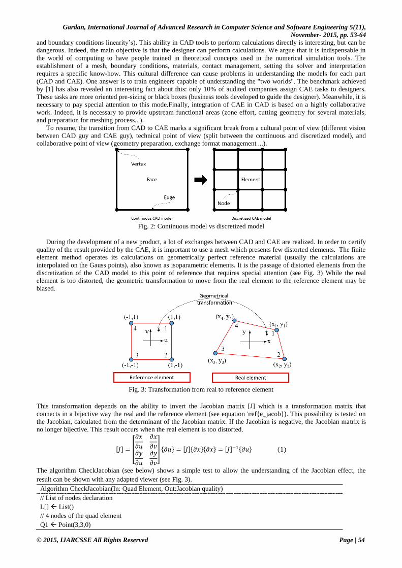
To resume, the transition from CAD to CAE marks a significant break from a cultural point of view (different vision
between CAD guy and CAE guy), technical point of view (split between the continuous and discretized model), and
collaborative point of view (geometry preparation, exchange format management ...).
Fig. 2: Continuous model vs discretized model
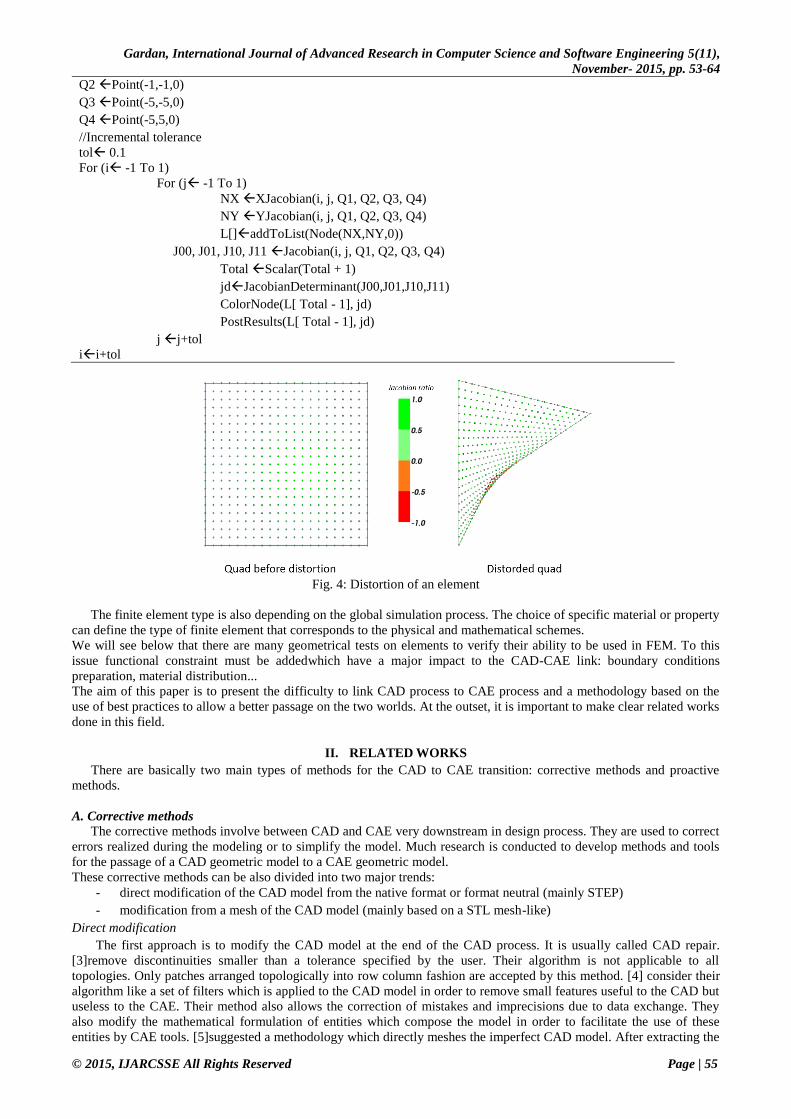
During the development of a new product, a lot of exchanges between CAD and CAE are realized. In order to certify
quality of the result provided by the CAE, it is important to use a mesh which presents few distorted elements. The finite
element method operates its calculations on geometrically perfect reference material (usually the calculations are
interpolated on the Gauss points), also known as isoparametric elements. It is the passage of distorted elements from the
discretization of the CAD model to this point of reference that requires special attention (see Fig. 3) While the real
element is too distorted, the geometric transformation to move from the real element to the reference element may be
biased.
Fig. 3: Transformation from real to reference element
This transformation depends on the ability to invert the Jacobian matrix [J] which is a transformation matrix that
connects in a bijective way the real and the reference element (see equation \ref{e_jacob}). This possibility is tested on
the Jacobian, calculated from the determinant of the Jacobian matrix. If the Jacobian is negative, the Jacobian matrix is
no longer bijective. This result occurs when the real element is too distorted.
𝐽 =
𝜕𝑥
𝜕𝑢
𝜕𝑥
𝜕𝑣𝜕𝑦
𝜕𝑢
𝜕𝑦
𝜕𝑣
𝜕𝑢 = 𝐽 𝜕𝑥 𝜕𝑥 = 𝐽 −1 𝜕𝑢 (1)
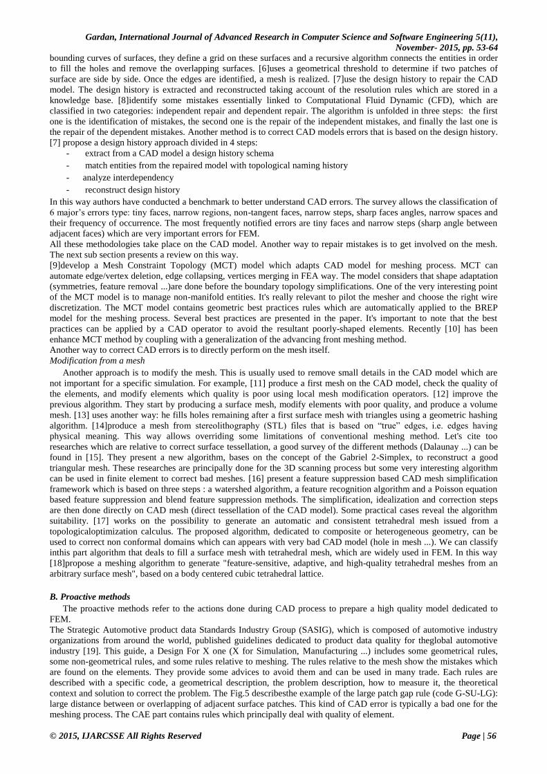
The algorithm CheckJacobian (see below) shows a simple test to allow the understanding of the Jacobian effect, the
result can be shown with any adapted viewer (see Fig. 3).
Algorithm CheckJacobian(In: Quad Element, Out:Jacobian quality)
// List of nodes declaration
L[] List()
// 4 nodes of the quad element
Q1 Point(3,3,0)
Gardan, International Journal of Advanced Research in Computer Science and Software Engineering 5(11),
November- 2015, pp. 53-64
© 2015, IJARCSSE All Rights Reserved Page | 55
Q2 Point(-1,-1,0)
Q3 Point(-5,-5,0)
Q4 Point(-5,5,0)
//Incremental tolerance
tol 0.1
For (i -1 To 1)
For (j -1 To 1)
NX XJacobian(i, j, Q1, Q2, Q3, Q4)
NY YJacobian(i, j, Q1, Q2, Q3, Q4)
L[]addToList(Node(NX,NY,0))
J00, J01, J10, J11 Jacobian(i, j, Q1, Q2, Q3, Q4)
Total Scalar(Total + 1)
jdJacobianDeterminant(J00,J01,J10,J11)
ColorNode(L[ Total - 1], jd)
PostResults(L[ Total - 1], jd)
j j+tol
ii+tol
Fig. 4: Distortion of an element
The finite element type is also depending on the global simulation process. The choice of specific material or property
can define the type of finite element that corresponds to the physical and mathematical schemes.
We will see below that there are many geometrical tests on elements to verify their ability to be used in FEM. To this
issue functional constraint must be addedwhich have a major impact to the CAD-CAE link: boundary conditions
preparation, material distribution...
The aim of this paper is to present the difficulty to link CAD process to CAE process and a methodology based on the
use of best practices to allow a better passage on the two worlds. At the outset, it is important to make clear related works
done in this field.
II. RELATED WORKS
There are basically two main types of methods for the CAD to CAE transition: corrective methods and proactive
methods.
A. Corrective methods
The corrective methods involve between CAD and CAE very downstream in design process. They are used to correct
errors realized during the modeling or to simplify the model. Much research is conducted to develop methods and tools
for the passage of a CAD geometric model to a CAE geometric model.
These corrective methods can be also divided into two major trends:
- direct modification of the CAD model from the native format or format neutral (mainly STEP)
- modification from a mesh of the CAD model (mainly based on a STL mesh-like)
Direct modification
The first approach is to modify the CAD model at the end of the CAD process. It is usually called CAD repair.
[3]remove discontinuities smaller than a tolerance specified by the user. Their algorithm is not applicable to all
topologies. Only patches arranged topologically into row column fashion are accepted by this method. [4] consider their
algorithm like a set of filters which is applied to the CAD model in order to remove small features useful to the CAD but
useless to the CAE. Their method also allows the correction of mistakes and imprecisions due to data exchange. They
also modify the mathematical formulation of entities which compose the model in order to facilitate the use of these
entities by CAE tools. [5]suggested a methodology which directly meshes the imperfect CAD model. After extracting the
Gardan, International Journal of Advanced Research in Computer Science and Software Engineering 5(11),
November- 2015, pp. 53-64
© 2015, IJARCSSE All Rights Reserved Page | 56
bounding curves of surfaces, they define a grid on these surfaces and a recursive algorithm connects the entities in order
to fill the holes and remove the overlapping surfaces. [6]uses a geometrical threshold to determine if two patches of
surface are side by side. Once the edges are identified, a mesh is realized. [7]use the design history to repair the CAD
model. The design history is extracted and reconstructed taking account of the resolution rules which are stored in a
knowledge base. [8]identify some mistakes essentially linked to Computational Fluid Dynamic (CFD), which are
classified in two categories: independent repair and dependent repair. The algorithm is unfolded in three steps: the first
one is the identification of mistakes, the second one is the repair of the independent mistakes, and finally the last one is
the repair of the dependent mistakes. Another method is to correct CAD models errors that is based on the design history.
[7] propose a design history approach divided in 4 steps:
- extract from a CAD model a design history schema
- match entities from the repaired model with topological naming history
- analyze interdependency
- reconstruct design history
In this way authors have conducted a benchmark to better understand CAD errors. The survey allows the classification of
6 major’s errors type: tiny faces, narrow regions, non-tangent faces, narrow steps, sharp faces angles, narrow spaces and
their frequency of occurrence. The most frequently notified errors are tiny faces and narrow steps (sharp angle between
adjacent faces) which are very important errors for FEM.
All these methodologies take place on the CAD model. Another way to repair mistakes is to get involved on the mesh.
The next sub section presents a review on this way.
[9]develop a Mesh Constraint Topology (MCT) model which adapts CAD model for meshing process. MCT can
automate edge/vertex deletion, edge collapsing, vertices merging in FEA way. The model considers that shape adaptation
(symmetries, feature removal ...)are done before the boundary topology simplifications. One of the very interesting point
of the MCT model is to manage non-manifold entities. It's really relevant to pilot the mesher and choose the right wire
discretization. The MCT model contains geometric best practices rules which are automatically applied to the BREP
model for the meshing process. Several best practices are presented in the paper. It's important to note that the best
practices can be applied by a CAD operator to avoid the resultant poorly-shaped elements. Recently [10] has been
enhance MCT method by coupling with a generalization of the advancing front meshing method.
Another way to correct CAD errors is to directly perform on the mesh itself.
Modification from a mesh
Another approach is to modify the mesh. This is usually used to remove small details in the CAD model which are
not important for a specific simulation. For example, [11] produce a first mesh on the CAD model, check the quality of
the elements, and modify elements which quality is poor using local mesh modification operators. [12] improve the
previous algorithm. They start by producing a surface mesh, modify elements with poor quality, and produce a volume
mesh. [13] uses another way: he fills holes remaining after a first surface mesh with triangles using a geometric hashing
algorithm. [14]produce a mesh from stereolithography (STL) files that is based on “true” edges, i.e. edges having
physical meaning. This way allows overriding some limitations of conventional meshing method. Let's cite too
researches which are relative to correct surface tessellation, a good survey of the different methods (Dalaunay ...) can be
found in [15]. They present a new algorithm, bases on the concept of the Gabriel 2-Simplex, to reconstruct a good
triangular mesh. These researches are principally done for the 3D scanning process but some very interesting algorithm
can be used in finite element to correct bad meshes. [16] present a feature suppression based CAD mesh simplification
framework which is based on three steps : a watershed algorithm, a feature recognition algorithm and a Poisson equation
based feature suppression and blend feature suppression methods. The simplification, idealization and correction steps
are then done directly on CAD mesh (direct tessellation of the CAD model). Some practical cases reveal the algorithm
suitability. [17] works on the possibility to generate an automatic and consistent tetrahedral mesh issued from a
topologicaloptimization calculus. The proposed algorithm, dedicated to composite or heterogeneous geometry, can be
used to correct non conformal domains which can appears with very bad CAD model (hole in mesh ...). We can classify
inthis part algorithm that deals to fill a surface mesh with tetrahedral mesh, which are widely used in FEM. In this way
[18]propose a meshing algorithm to generate "feature-sensitive, adaptive, and high-quality tetrahedral meshes from an
arbitrary surface mesh", based on a body centered cubic tetrahedral lattice.
B. Proactive methods
The proactive methods refer to the actions done during CAD process to prepare a high quality model dedicated to
FEM.
The Strategic Automotive product data Standards Industry Group (SASIG), which is composed of automotive industry
organizations from around the world, published guidelines dedicated to product data quality for theglobal automotive
industry [19]. This guide, a Design For X one (X for Simulation, Manufacturing ...) includes some geometrical rules,
some non-geometrical rules, and some rules relative to meshing. The rules relative to the mesh show the mistakes which
are found on the elements. They provide some advices to avoid them and can be used in many trade. Each rules are
described with a specific code, a geometrical description, the problem description, how to measure it, the theoretical
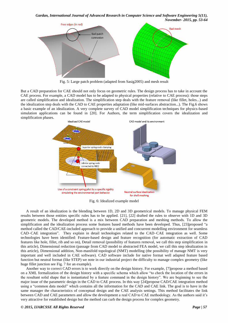
context and solution to correct the problem. The Fig.5 describesthe example of the large patch gap rule (code G-SU-LG):
large distance between or overlapping of adjacent surface patches. This kind of CAD error is typically a bad one for the
meshing process. The CAE part contains rules which principally deal with quality of element.
Gardan, International Journal of Advanced Research in Computer Science and Software Engineering 5(11),
November- 2015, pp. 53-64
© 2015, IJARCSSE All Rights Reserved Page | 57
Fig. 5: Large patch problem (adapted from Sasig2005) and mesh result
But a CAD preparation for CAE should not only focus on geometric rules. The design process has to take in account the
CAE process. For example, a CAD model has to be adapted to physical properties (relative to CAE process): those steps
are called simplification and idealization. The simplification step deals with the feature removal (like fillet, holes...) and
the idealization step deals with the CAD to CAE properties adaptation (like mid-surfaces abstraction...). The Fig.6 shows
a basic example of an idealization. A very complete survey of CAD model simplification techniques for physics-based
simulation applications can be found in [20]. For Authors, the term simplification covers the idealization and
simplification phases.
Fig. 6: Idealized example model
A result of an idealization is the blending between 1D, 2D and 3D geometrical models. To manage physical FEM
results between those entities specific rules has to be applied. [21], [22] drafted the rules to observe with 1D and 3D
geometric models. The developed method is a mix between CAD preparation and meshing methods. To allow the
simplification and the idealization process some features based methods have been developed. Thus, [23]proposed “a
method called the CAD/CAE-included approach to provide a unified and concurrent modelling environment for seamless
CAD–CAE integration”. They explain in detail technologies related to the CAD–CAE integration as well. Some
technologies have been identified: Feature-based design and feature recognition (for automatic extraction of CAD
features like hole, fillet, rib and so on), Detail removal (possibility of features removal, we call this step simplification in
this article), Dimensional reduction (passage from CAD model to abstracted FEA model, we call this step idealization in
this article), Dimensional addition, Non-manifold topological (NMT) modelling (the possibility of manage NMT is very
important and well included in CAE software). CAD software include for native format well adapted feature based
function but neutral format (like STEP) we note in our industrial project the difficulty to manage complex geometry (like
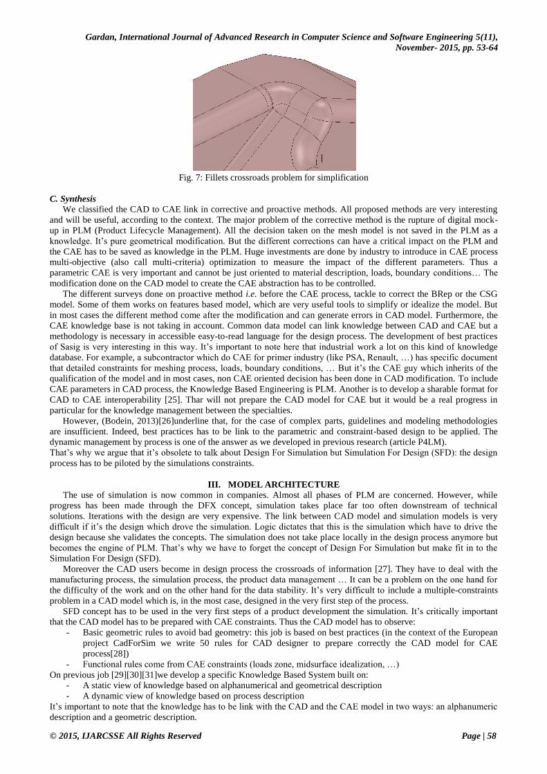
huge fillet junction see Fig. 7 for an example).
Another way to correct CAD errors is to work directly on the design history. For example, [7]propose a method based
on a XML formalization of the design history with a specific schema which allow “to check the location of the errors in
the resultant solid shape that is instantiated by a feature command in the design history”. We are beginning to see the
major issue of the parametric design in the CAD to CAE process. In this way [24]propose CAD/CAE integration method
using a “common data model” which contains all the information for the CAD and CAE link. The goal is to have in the
same manager the characteristics of conceptual design and the CAE analysis settings. This method facilitates the link
between CAD and CAE parameters and allow the development a real CAD to CAE methodology. As the authors said it’s
very attractive for established design but the method can curb the design process for complex geometry.
Gardan, International Journal of Advanced Research in Computer Science and Software Engineering 5(11),
November- 2015, pp. 53-64
© 2015, IJARCSSE All Rights Reserved Page | 58
Fig. 7: Fillets crossroads problem for simplification
C. Synthesis
We classified the CAD to CAE link in corrective and proactive methods. All proposed methods are very interesting
and will be useful, according to the context. The major problem of the corrective method is the rupture of digital mock-
up in PLM (Product Lifecycle Management). All the decision taken on the mesh model is not saved in the PLM as a
knowledge. It’s pure geometrical modification. But the different corrections can have a critical impact on the PLM and
the CAE has to be saved as knowledge in the PLM. Huge investments are done by industry to introduce in CAE process
multi-objective (also call multi-criteria) optimization to measure the impact of the different parameters. Thus a
parametric CAE is very important and cannot be just oriented to material description, loads, boundary conditions… The
modification done on the CAD model to create the CAE abstraction has to be controlled.
The different surveys done on proactive method i.e. before the CAE process, tackle to correct the BRep or the CSG
model. Some of them works on features based model, which are very useful tools to simplify or idealize the model. But
in most cases the different method come after the modification and can generate errors in CAD model. Furthermore, the
CAE knowledge base is not taking in account. Common data model can link knowledge between CAD and CAE but a
methodology is necessary in accessible easy-to-read language for the design process. The development of best practices
of Sasig is very interesting in this way. It’s important to note here that industrial work a lot on this kind of knowledge
database. For example, a subcontractor which do CAE for primer industry (like PSA, Renault, …) has specific document
that detailed constraints for meshing process, loads, boundary conditions, … But it’s the CAE guy which inherits of the
qualification of the model and in most cases, non CAE oriented decision has been done in CAD modification. To include
CAE parameters in CAD process, the Knowledge Based Engineering is PLM. Another is to develop a sharable format for
CAD to CAE interoperability [25]. Thar will not prepare the CAD model for CAE but it would be a real progress in
particular for the knowledge management between the specialties.
However, (Bodein, 2013)[26]underline that, for the case of complex parts, guidelines and modeling methodologies
are insufficient. Indeed, best practices has to be link to the parametric and constraint-based design to be applied. The
dynamic management by process is one of the answer as we developed in previous research (article P4LM).
That’s why we argue that it’s obsolete to talk about Design For Simulation but Simulation For Design (SFD): the design
process has to be piloted by the simulations constraints.
III. MODEL ARCHITECTURE
The use of simulation is now common in companies. Almost all phases of PLM are concerned. However, while
progress has been made through the DFX concept, simulation takes place far too often downstream of technical
solutions. Iterations with the design are very expensive. The link between CAD model and simulation models is very
difficult if it’s the design which drove the simulation. Logic dictates that this is the simulation which have to drive the
design because she validates the concepts. The simulation does not take place locally in the design process anymore but
becomes the engine of PLM. That’s why we have to forget the concept of Design For Simulation but make fit in to the
Simulation For Design (SFD).
Moreover the CAD users become in design process the crossroads of information [27]. They have to deal with the
manufacturing process, the simulation process, the product data management … It can be a problem on the one hand for
the difficulty of the work and on the other hand for the data stability. It’s very difficult to include a multiple-constraints
problem in a CAD model which is, in the most case, designed in the very first step of the process.
SFD concept has to be used in the very first steps of a product development the simulation. It’s critically important
that the CAD model has to be prepared with CAE constraints. Thus the CAD model has to observe:
- Basic geometric rules to avoid bad geometry: this job is based on best practices (in the context of the European
project CadForSim we write 50 rules for CAD designer to prepare correctly the CAD model for CAE
process[28])
- Functional rules come from CAE constraints (loads zone, midsurface idealization, …)
On previous job [29][30][31]we develop a specific Knowledge Based System built on:
- A static view of knowledge based on alphanumerical and geometrical description
- A dynamic view of knowledge based on process description
It’s important to note that the knowledge has to be link with the CAD and the CAE model in two ways: an alphanumeric
description and a geometric description.
Gardan, International Journal of Advanced Research in Computer Science and Software Engineering 5(11),
November- 2015, pp. 53-64
© 2015, IJARCSSE All Rights Reserved Page | 59
Knowledge modeling in static view
It’s important to note that the knowledge has to be linkedwith the CAD and the CAE model in two ways: an
alphanumeric description and a geometric description. Parametric modeling put constraints on geometric model to design
modification or to engineering analysis. Constraints can be geometrical one (one entity is tangent to another) or
knowledge-based one (e.g. trade rules, constraints). Functional design has to be represented by the vocabulary of the
domain. This vocabulary is then used in the definition of trade rules, constraints... Thus, we define specific expression
called GraphoNumerical Expression (GNE) and specific parameters called GraphoNumerical Parameters (GNP). The
particularity of GNE/GNP is to link the vocabulary to knowledge and to geometry.
A GNE is an expression based on a prerecorded vocabulary (saved on KBS data system) that allows user to describe an
action. In program manager system described in the next section, a completion automation forces the use of the recorded
terms. A GNE contains three classes of different terms. These terms are different according to the context.
Action class A = {e_id, verb1, verb2, verb3…}
Object class A = {e_id, term1, term2, term3…}
Constraint class A = {e_id, term1, term2, term3…}
Here are the three classes with some examples of terms:
- Action class (create, destroy, modify, consult, remove, apply, to radiate, etc)
- Object class (part, clearance, hole, rib, face, line, edge, point, node, element etc)
- Constraint class (at a tangent to, parallel to, symmetric to, force, pressure, length, etc)
A GNE is an n-tuple {A,O,C, ..}.
A GNE can contain one or several GNP. A GNP is constructed automatically by the graphonumerical engine and can
have two kind of link:
- an alphanumerical one to link knowledge to value, it’s an acquisition action.
- a geometrical one to link knowledge to geometry. In this case a specific identifying is saved to automatically ask
in the process an identification action to the user.
The Fig. 7 shows a basic example for the creation of a circle tangent to 2 lines with a define radius. The two GNP have
been created directly from the EGN and can be incorporated in CAD or CAE model. The geometrical values are
references from the CAD or the CAE model. This kind of reference is called BREP_REF_PGN*_*** for CAD model or
FEM_REF_PGN*_*** where PGN* is the linked PGN and the next *** the reference number. Those references require
that the user pick in the geometry the associated BREP or FEM geometrical reference.
Fig. 7: EGN-PGN example
Knowledge modelling in dynamic view
Scenarios represent a succession of tasks whose implementation contributes to the modification of the product. We
are interested for our research [32]in the case based reasoning [33]and in one of its components in particularly i.e. the
decomposition of a problem in a series of tasks [34]. The technique of case based reasoning makes it possible to find a
solution to a problem in finding similar solution in a base of cases. We base ourselves on the fact that each time that an
expert resolves a problem, he runs in an intuitive way a scenario (can be called a script or a process). Schank set up this
structure by affirming that there are thousands of scripts in the human memory. The designers set up in an often intuitive
way scenarios of design before beginning the design of a part. However, it is well-known that the most of CADsystems
users set up methodologies of design which provide the broad outline of design (with simulation constraint). In the
remainder of this paper we call a scenario or a script a process. The process modeling is the backbone of the SFD
concept. In our model a process is a succession of GNE which generate GNP for the linked GNE or for the CAD/CAE
model (see Fig. 8).
Gardan, International Journal of Advanced Research in Computer Science and Software Engineering 5(11),
November- 2015, pp. 53-64
© 2015, IJARCSSE All Rights Reserved Page | 60
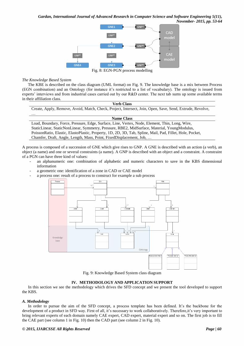
Fig. 8: EGN-PGN process modelling
The Knowledge Based System
The KBE is described on the class diagram (UML format) on Fig. 9. The knowledge base is a mix between Process
(EGN combination) and an Ontology (for instance it’s restricted to a list of vocabulary). The ontology is issued from
experts’ interviews and from industrial cases carried out by our R&D center. The next tab sums up some available terms
in their affiliation class.
Verb Class
Create, Apply, Remove, Avoid, Match, Check, Project, Intersect, Join, Open, Save, Send, Extrude, Revolve,
…
Name Class
Load, Boundary, Force, Pressure, Edge, Surface, Line, Vertex, Node, Element, Thin, Long, Wire,
StaticLinear, StaticNonLinear, Symmetry, Pressure, RBE2, MidSurface, Material, YoungModulus,
PoissonRatio, Elastic, ElastoPlastic, Property, 1D, 2D, 3D, Tab, Spline, Mail, Pad, Fillet, Hole, Pocket,
Chamfer, Draft, Angle, Length, Mass, Point, FixedDisplacement, Job, …
A process is composed of a succession of GNE which give rises to GNP. A GNE is described with an action (a verb), an
object (a name) and one or several constraints (a name). A GNP is described with an object and a constraint. A constraint
of a PGN can have three kind of values:
- an alphanumeric one: combination of alphabetic and numeric characters to save in the KBS dimensional
information
- a geometric one: identification of a zone in CAD or CAE model
- a process one: result of a process to construct for example a sub process
Fig. 9: Knowledge Based System class diagram
IV. METHODOLOGY AND APPLICATION SUPPORT
In this section we see the methodology which drives the SFD concept and we present the tool developed to support
the KBS.
A. Methodology
In order to pursue the aim of the SFD concept, a process template has been defined. It’s the backbone for the
development of a product in SFD way. First of all, it’s necessary to work collaboratively. Therefore,it’s very important to
bring relevant experts of each domain namely CAE expert, CAD expert, material expert and so on. The first job is to fill
the CAE part (see column 1 in Fig. 10) then the CAD part (see column 2 in Fig. 10).
Gardan, International Journal of Advanced Research in Computer Science and Software Engineering 5(11),
November- 2015, pp. 53-64
© 2015, IJARCSSE All Rights Reserved Page | 61
Fig.10: Process template
The “Create analysis” action consists in the declaration of the calculus: type (linear, non linear …), convergence set…
Then the “Loads and BC’s” define the loads and the boundary conditions of the model. If a CAD model exist, loads and
boundary conditions can be associated to geometric entities. Otherwise a specific GNP can be created to inquire the
system with a specific reference. When the process is running the system can ask to identify a geometric entity. Fig. 11
shows an example of this interaction with Catia V5 CAD software.
Fig. 11: Interaction example with Catia V5
B. Tool support
A tool, called DFX@Manager, has been developed to link the KBS, the SFD methodology to CAD and CAE tools
(C++ code with VTK visualization). For instance, two links are available: Catia V5 (DassaultSystèmes) link for CAD
and Hypermesh/Optistruct (linear calculus) (Altair) for CAE. This tool allows the creation of process and sub-process in
SFD way (see Fig. 12). Actors involve in the project can be associated to send information with the planning process.
Fig. 12: DFX@Manager view with SFD model
Gardan, International Journal of Advanced Research in Computer Science and Software Engineering 5(11),
November- 2015, pp. 53-64
© 2015, IJARCSSE All Rights Reserved Page | 62
Each task is associated with EGNengine which create PGN. Best practices are linked to task with associated files.
Fig. 13: EGN/PGN engine and link with task of process
When process and sub-processes are created with all experts involved in the project, the system run it and automatically
creates PGN in CAD and CAE software to help CAD guy and CAE guy in the development of the product.
V. APPLICATION ON INDUSTRIAL CASE
Many industrial applications have been processed with SFD methodology and DFX@Manager tool. One of these
examples presents a fully operational system developed for Faurecia AST (Acoustic and Soft Trim) to efficiently manage
the SFD issue. The production service, the CAD expert and the CAE expert was gathered together to include their skills.
Faurecia is an industrial supplier for some of the largest automakers. The AST Product Line research center contributes
to car’s interior acoustics by optimizing the insulation of the trunk compartment, through the package tray (the rear
parcel shelf, which sits below the back window). Faurecia AST uses some of the most sophisticated acoustic analysis and
simulation tools in the world to fulfill the main function of the package tray. However, they still need a full 3D CAD
model to work and this model will only be the result of the collaborative design between them, the car manufacturer and
its designers. Thus, while dealing with a quote request, the subcontractor faces two choices: either he realizes the full
design process (CAD / CAE) to be able to provide a realistic quotation; either he cuts a global deal, taking the risk to be
rejected with a too high proposal or chosen with a too lower bid and having to work at a loss. Neither of those choices
feels reasonable. Even if we consider that some steps of the design do not widely affect the estimate, some of them must
weigh in.
Let’s consider the example of an acquisition phase endured by Faurecia. When they receive a quotation request,
including specification, they have to provide the car manufacturer with an evaluation of the production costs. Those costs
are inferred from design, material, and manufacturing process. However, the design and material choice cannot rationally
be evaluated for each request. They are too time and resource consuming to be studied. For example, Faurecia evaluates
that, to provide the best design and material solution upon a specification set, at least 10 design iterations (CAD with
validation through mechanical simulation) must be done. Each iteration requires 3 days of work (see Fig. 14). This means
that, to be objective, a design team would need at least 30 working days (meaning more than one and half month) to
provide the prime contractor with a relevant answer. This is obviously not acceptable, for both parties. We could add that
this design is likely to be useless, since this was only a first negotiation using a draft/decoy shelf as test subject.
Fig. 14: Design process: design and analysis (including meshing, calculation and results analysis) are time consuming
operations
To solve this problem, it was necessary to find a methodology to cater for these specifications.We are based our work on
the methodology SFD with the following constraints:
- Help the designer to go faster by integrating knowledge from manufacturing process and knowledge from
simulation process
- Ensure that the CAD model complies with the rules for obtaining a proper model for the simulation
- Automate as much tasks as possible
Furthermore, DFX @ Manager Utilizes the tools were Catia V5 and Abaqus.
Gardan, International Journal of Advanced Research in Computer Science and Software Engineering 5(11),
November- 2015, pp. 53-64
© 2015, IJARCSSE All Rights Reserved Page | 63
VI. CONCLUSION AND FUTURE TRENDS
As we see the link between CAD and CAE is really not obvious. To resume there are two ways to simplify it: adapt
the CAD model for the CAE process with automation or use methodology to design directly CAE constraints in CAD.
We argue that the second one is the best way in the PLM concept. It allows to not break the numerical model and keep
the design intent of the digital mock-up. Our methodology, called Simulation For Design, is based on process modelling,
the use of best practices and a specific knowledge representation. She is currently used in our industrial assistance (we
help over 40 SME’s per year in their CAD/CAE projects) with success. The first draft of the DFX@Manager tool (allow
the management of the methodology SFD) is currently improved to be used by the industry.
ACKNOWLEDGMENT
This work is based on CADFORSIM, a European collaborative Project between France and Turkey, with grants from
the Ardennes department and the Champagne-Ardenne region.
REFERENCES
[1] N. Gardan and F. LeMeec, “Benchmark on the use of numerical simulation in R&D, MICADO/DINCCS,” in
VirtualPLM’12, Reims, 2012.
[2] Y. Bodein, B. Rose, and E. Caillaud, “Explicit reference modeling methodology in parametric {CAD} system,”
Comput. Ind., no. 0, p. -, 2013.
[3] A. E. Uva, G. Monno, and B. Hamann, “A new method for the repair of CAD data with discontinuities,” in
Proceedings Convegno Italo-Spagnolo – Progettazione e Fattibilita dei Prodotti Industriali, Naples, Italy, 1998.
[4] R. Riba, G. Bugeda, and E. Onate, “Some algorithms to correct a geometry in order to create a finite element
mesh,” Comput. Struct., vol. 80, pp. 1399 – 1408, 2002.
[5] J. P. Steinbrenner, N. J. Wyman, and J. R. Chawner, “Fast Surface Meshing on Imperfect CAD Models,” in in
9th International Meshing Rountable, 2000, p. 9.
[6] P. Laug, “Some Aspects of Parametric Surface Meshing,” Finite Elem Anal Des, vol. 46, no. 1–2, pp. 216–226,
Jan. 2010.
[7] J. Yang and S. Han, “Repairing CAD model errors based on the design history,” Comput.-Aided Des., vol. 38,
no. 6, pp. 627–640, Jun. 2006.
[8] A. A. Mezentsev and T. Woehler, “Methods And Algorithms Of Automated CAD Repair For Incremental
Surface Meshing,” in Proc. 8 th Int. Meshing Roundtable, Sandia report SAND 99-2288, 1999, pp. 299–309.
[9] G. Foucault, J.-C. Cuillière, V. FranÃ\Sois, J.-C. LÃ\copyrighton, and R. Maranzana, “Adaptation of CAD
model topology for finite element analysis,” Comput.-Aided Des., vol. 40, no. 2, pp. 176 – 196, 2008.
[10] G. Foucault, J.-C. CuilliÚre, V. FranÃ\Sois, J.-C. LÃ\copyrighton, and R. Maranzana, “Generalizing the
advancing front method to composite surfaces in the context of meshing constraints topology,” Comput.-Aided
Des., vol. 45, no. 11, pp. 1408 – 1425, 2013.
[11] S. Dey, M. S. Shephard, and M. K. Georges, “Elimination of the adverse effects of small model features by the
local modification of automatically generated meshes,” Eng. Comput., vol. 13, no. 3, pp. 134–152, 1997.
[12] S. Beall, M. S. Shephard, M. W. Beall, and R. M. O’bara, “Revisiting the Elimination of the Adverse Effects of
Small Model Features in Automatically Generated Meshes,” Proc 7th Int. Meshing Roundtable 98 SAND 98-
2250 Sandia, vol. 13, pp. 119–131, 1998.
[13] G. Barequet, Geometric hashing and its applications in Database and Data Communication Network Systems:
Techniques and Applications. Elsevier Science & Technology Books, 2002.
[14] E. Béchet, J.-C. Cuilliere, and F. Trochu, “Generation of a finite element {MESH} from stereolithography
(STL) files,” Comput.-Aided Des., vol. 34, no. 1, pp. 1 – 17, 2002.
[15] L. Di Angelo, P. Di Stefano, and L. Giaccari, “A new mesh-growing algorithm for fast surface reconstruction,”
Comput.-Aided Des., vol. 43, no. 6, pp. 639–650, Jun. 2011.
[16] S. Gao, W. Zhao, H. Lin, F. Yang, and X. Chen, “Feature suppression based CAD mesh model simplification,”
Comput.-Aided Des., vol. 42, no. 12, pp. 1178–1188, Dec. 2010.
[17] J.-C. Cuillière, V. François, and J.-M. Drouet, “Automatic mesh generation and transformation for topology
optimization methods,” Comput.-Aided Des., vol. 45, no. 12, pp. 1489–1506, Dec. 2013.
[18] J. Wang and Z. Yu, “Feature-sensitive tetrahedral mesh generation with guaranteed quality,” Comput.-Aided
Des., vol. 44, no. 5, pp. 400–412, May 2012.
[19] SASIG, Product Data Quality for the Global Automotive Industry, Sasig. 2005.
[20] A. Thakur, A. G. Banerjee, and S. K. Gupta, “A survey of CAD model simplification techniques for physics-
based simulation applications,” Comput.-Aided Des., vol. 41, no. 2, pp. 65–80, Feb. 2009.
[21] S. Bournival, J.-C. Cuillière, and V. François, “A mesh-geometry based method for coupling 1D and 3D
elements,” Adv. Eng. Softw., vol. 41, no. 6, pp. 838 – 858, 2010.
[22] J.-C. Cuillière, S. Bournival, and V. François, “A mesh-geometry-based solution to mixed-dimensional
coupling,” Comput.-Aided Des., vol. 42, no. 6, pp. 509 – 522, 2010.
[23] S. H. Lee, “A CAD–CAE integration approach using feature-based multi-resolution and multi-abstraction
modelling techniques,” Comput.-Aided Des., vol. 37, no. 9, pp. 941–955, Aug. 2005.
[24] G. P. Gujarathi and Y.-S. Ma, “Parametric CAD/CAE integration using a common data model,” J. Manuf. Syst.,
vol. 30, no. 3, pp. 118–132, Aug. 2011.
Gardan, International Journal of Advanced Research in Computer Science and Software Engineering 5(11),
November- 2015, pp. 53-64
© 2015, IJARCSSE All Rights Reserved Page | 64
[25] B.-K. Park and J. J. Kim, “A sharable format for multidisciplinary finite element analysis data,” Comput.-Aided
Des., vol. 44, no. 7, pp. 626 – 636, 2012.
[26] Y. Bodein, B. Rose, and E. Caillaud, “A roadmap for parametric {CAD} efficiency in the automotive industry,”
Comput.-Aided Des., vol. 45, no. 10, pp. 1198 – 1214, 2013.
[27] B. F. Robertson and D. F. Radcliffe, “Impact of {CAD} tools on creative problem solving in engineering
design,” Comput.-Aided Des., vol. 41, no. 3, pp. 136 – 146, 2009.
[28] M. Reimeringer, N. Gardan, F. Danesi, and A. Hugur, “CADFORSIM: Rules to improve the mesh quality,” in
TMCE 2008 Symposium, Izmir, Turquie, 2008.
[29] N. Gardan, “Automatic modelling of sand casting filling systems on the Internet,” Rev. Fondeur D’aujourd’hui
Rubr. Rech. Res., vol. 229, pp. 26–35, 2003.
[30] F. Danesi, N. Gardan, Y. Gardan, and M. Reimeringer, “P4LM: A methodology for product lifecycle
management,” Comput. Ind., vol. 59, no. 2–3, pp. 304–317, 2008.
[31] F. Danesi, N. Gardan, and E. Kwassi, “Knowledge Based Engineering Optimization and Interoperability: An
Automotive Case-Study,” Appl. Mech. Mater., vol. 232, pp. 823–827, 2012.
[32] N. Gardan and Y. Gardan, “An application of knowledge based modelling using scripts,” Expert Syst. Appl., vol.
25, no. 4, pp. 555–568, 2003.
[33] R. C. Schank, Dynamic Memory: A Theory of Reminding and Learning in Computers and People. New York,
NY, USA: Cambridge University Press, 1983.
[34] A. Aamodt and E. Plaza, “Case-based Reasoning: Foundational Issues, Methodological Variations, and System
Approaches,” AI Commun, vol. 7, no. 1, pp. 39–59, Mar. 1994.