spects for High-Frequency Calibrati ith the SMA Dual-IF/Receiver Syste Todd R. Hunter, Jun-Hui Zhao (CfA) Sheng-Yuan Liu, Yu-Nung Su, Vivien Chen (ASIAA) Based on data from February 2005 “690 GHz Campaign”
Transcript
Prospects for High-Frequency Calibration with the SMA Dual-IF/Receiver System
Todd R. Hunter, Jun-Hui Zhao (CfA) Sheng-Yuan Liu, Yu-Nung Su, Vivien Chen (ASIAA)
Based on data from February 2005 “690 GHz Campaign”
Lack of Strong Gain Calibrators
SMA sensitivity: Tsys ~ 100 K at 230 GHz (10 mJy in 5 min) Tsys ~ 2500 K at 690 GHz (250 mJy in 5 min)
For good phase solutions, we need S/N ~ 10 per baseline
0.5 Jy at 230 GHz (70 quasars with F > 1Jy)10 Jy at 690 GHz (maybe 1 or 2 quasars)
Investigation of “Phase transfer” Part II. Search for phase relationships
1. Do passband calibration of calibrator and target
2. Do phase-only selfcal on calibrator at 230 & 690
3. Examine correlations of 690 vs 230 phase solutions
4. Flag any phase jumps or unstable periods that degrade the correlation
5. Compute slope and offset relating 230 and 690 phases on each antenna
Ceres 690 Selfcal
Example #0: phase transfer using Ceres (on itself)
Ceres phase transfer imageCeres 690 uncalibrated data
Derivecoefficients
and 690 gain table
Apply690 gain
table
Ceres 230 Selfcal (rms = 50 mJy, S/N = 260)
(rms = 70 mJy, S/N = 193)
+
Investigation of “Phase transfer” Part III: Imaging tests
1.Selfcal the test target at 230 GHz
2.Apply slope & offset from the phase transfer calibrator to create a new gain table appropriate for 690 GHz
2. Image the test target at 690 GHz using the new gain table
3. Compare with image from “normal” calibration
Example #1: phase transfer on a point source
690 GHz phase transfer (S/N=5)
Apply coefficientsfrom Ceres
to make690 gain
table
Quasar 1743-038230 GHz selfcal solution
Direct 690 GHz calibration (S/N=8)
Apply690 gain
table
690 GHz uncalibrated data
The phase transfer analyses in the previous slides were done in Miriad. Here is an example done in MIR / IDL (see poster 4.69 by Su & Liu).In this case, the frequency ratio (rather than the fit) was used in the scaling.
Phase transfer from quasar 1743-038
Example #2: phase transfer on IRAS 16293-2422
Direct 690GHz calibration (Ceres)
Summary of 690 GHz calibration schemes in the “compact” configuration (1” to 5”)
Method Advantages Disadvantages
1. Direct 690 calibration using minor planet
Most direct approach, does not require dual-IF phase stability
Calibrator often quite distant from target (over 40 degrees)
2. Phase transfer using minor planet plus nearby quasar
Can use quasar close to target – better positions
Requires dual-IF phase stability and measurement of phase slope and offset
3. Phase transfer using 215 / 658 GHz masers
Additional pool of compact sources close to target. Might be only solution for extended arrays.
Arbitrary spectral line setups not feasible (or frequent re-tuning required).
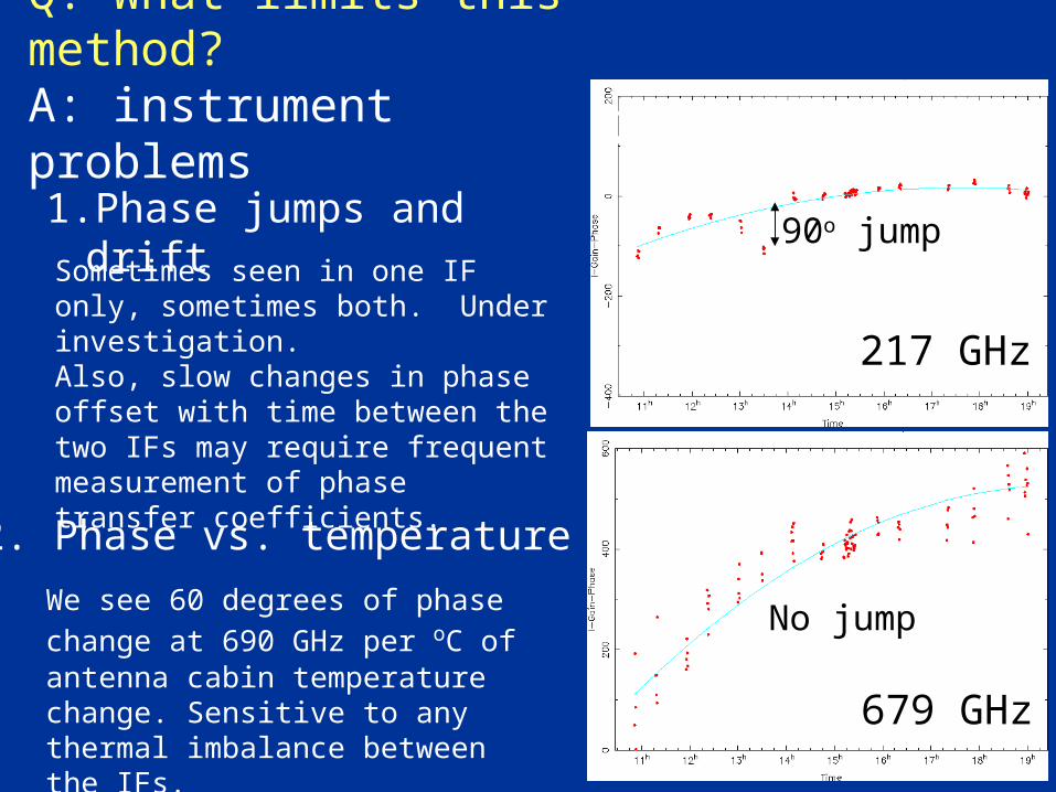
Q: What limits this method?A: instrument problems
1.Phase jumps and drift90o jump
230GHz
Sometimes seen in one IF only, sometimes both. Under investigation.Also, slow changes in phase offset with time between the two IFs may require frequent measurement of phase transfer coefficients.
We see 60 degrees of phase change
at 690 GHz per oC of antenna cabin temperature change. Sensitive to any thermal imbalance between the IFs.
2. Phase vs. temperature
No jump
217 GHz
679 GHz
1. Passband measurements in extended configs• No point sources (< 0.4”) bright enough • Can we use Lunar limb? (works for measuring delays)• Noise source for passband phases?• Autocorrelation on the ambient load for amplitudes?
2. Weather?• So far, best dual-freq. phase correlations occur on nights with little wind (< 10 mph, January 28), or constant wind direction (February 18, March 02) . Coincidence? More experience may tell us.
Other limitations for 690 GHz calibration
Summary and future work• We have demonstrated our first attempt at phase transfer at submm frequencies
• Improvements are possible:Cabin temperature control (antenna 6 now < 0.1 oC RMS) Phase jump investigation (and elimination)
• New receiver band coming (320-420 GHz)Will allow more frequent dual-band observations (due to less stringent weather requirements) and higher S/N testing of the phase transfer technique.
Conclusion: We remain open-minded and hopefulto realize the full potential of the SMA.