Page 1
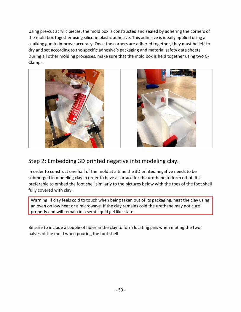
PROSTHETIC FOOT SHELL, QL+
FINAL DESIGN REVIEW
JUNE 8, 2020
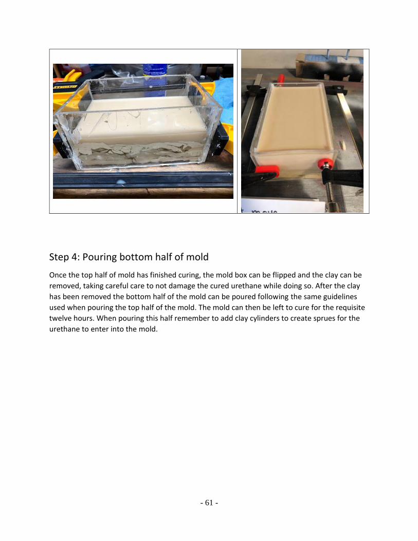
TEAM: COAST BUSTERS
KATHRYN VERSTEEG – [email protected]
JACKSON TUCKER – [email protected]
ETHAN FREY – [email protected]
Page 2
Statement of Disclaimer
Since this project is a result of a class assignment, it has been graded and accepted as fulfillment
of the course requirements. Acceptance does not imply technical accuracy or reliability. Any use
of information in this report is done at the risk of the user. These risks may include catastrophic
failure of the device or infringement of patent or copyright laws. California Polytechnic State
University at San Luis Obispo and its staff cannot be held liable for any use or misuse of the
project. Additionally, due to the coronavirus pandemic of Spring 2020, this project was not
finished and is incomplete which will be reflected in the remainder of the report.
Page 3
TABLE OF CONTENTS
Abstract ....................................................................................................................................... - 1 -
1. Introduction ............................................................................................................................. - 1 -
2. Background ............................................................................................................................. - 2 -
2.1. Meetings with Sponsor ..................................................................................................... - 2 -
2.2. Existing Designs and Patent Research .............................................................................. - 2 -
2.3. Technical Information and Research ................................................................................ - 4 -
3. Objectives ............................................................................................................................... - 6 -
3.1. Problem Statement ............................................................................................................ - 6 -
3.2. Boundary Diagram ........................................................................................................... - 6 -
3.3. Quality Function Deployment (QFD) ............................................................................... - 7 -
4. Concept Design ....................................................................................................................... - 8 -
4.1 Ideation Process ................................................................................................................. - 8 -
4.2 Concept Prototype ........................................................................................................... - 10 -
5. Final Design .......................................................................................................................... - 12 -
5.1 Design Description .......................................................................................................... - 12 -
5.2 Design Justification ......................................................................................................... - 15 -
5.3 Design Changes Since CDR ............................................................................................ - 16 -
6. Manufacturing ....................................................................................................................... - 16 -
6.1 Procurement ..................................................................................................................... - 16 -
6.2 Initial Manufacturing Plans ............................................................................................. - 17 -
6.2.1 Manufacturing Plan 1 ............................................................................................... - 17 -
6.2.2 Manufacturing Plan 2 ............................................................................................... - 17 -
6.2.3 Manufacturing Plan 3 ............................................................................................... - 17 -
6.3 Manufacturing the Mold Box .......................................................................................... - 18 -
6.4 Creating Outer Foot Shell Mold ...................................................................................... - 18 -
6.4.1 Initial Testing Procedures ........................................................................................ - 21 -
6.5 Creating the Final Foot Shell ........................................................................................... - 23 -
6.6 3D Printed Components................................................................................................... - 24 -
6.7 Challenges.. ..................................................................................................................... - 25 -
6.8 Recommendations ........................................................................................................... - 25 -
Page 4
7. Design Verification ............................................................................................................... - 26 -
7.1 Specifications and Tests .................................................................................................. - 26 -
7.1.1 Cycles to Failure ...................................................................................................... - 26 -
7.1.2 Weight ...................................................................................................................... - 26 -
7.1.3 Fit ............................................................................................................................. - 26 -
7.1.4 Appearance .............................................................................................................. - 26 -
7.1.5 Time to Use .............................................................................................................. - 26 -
7.1.6 Weather Resistant .................................................................................................... - 27 -
7.1.7 Total Cost ................................................................................................................. - 27 -
7.1.8 ISO Testing .............................................................................................................. - 27 -
7.2 Completed Testing .............................................................................................................. - 27 -
7.3 Future Testing ..................................................................................................................... - 29 -
7.3.1 Test Fixture ...................................................................................................................... - 29 -
7.3.2 Testing Procedure ............................................................................................................ - 30 -
8. Project Management ............................................................................................................. - 30 -
9. Conclusion ............................................................................................................................ - 31 -
9.1 Project Reflection ............................................................................................................ - 31 -
9.2 Next Steps ...................................................................................................................... - 33 -
10. References ........................................................................................................................... - 34 -
Appendix A ............................................................................................................................... - 35 -
Appendix B ............................................................................................................................... - 36 -
Appendix C ............................................................................................................................... - 37 -
Appendix D ............................................................................................................................... - 38 -
Appendix E ............................................................................................................................... - 40 -
Appendix F................................................................................................................................ - 41 -
Appendix G ............................................................................................................................... - 42 -
Appendix H ............................................................................................................................... - 44 -
Appendix I ................................................................................................................................ - 45 -
Appendix J ................................................................................................................................ - 46 -
Appendix K ............................................................................................................................... - 47 -
Appendix L ............................................................................................................................... - 52 -
Page 5
Appendix M .............................................................................................................................. - 56 -
Appendix N ............................................................................................................................... - 58 -
Appendix O ............................................................................................................................... - 66 -
Page 6
- 1 -
ABSTRACT
This final design review includes an overview of our project and the steps we have taken to
create our final product. We discuss the background research conducted, including various
products like the foot shell we are trying to design and its related patents, along with similar past
senior projects. As our product is considered a medical device, there are also certain standards
that we must comply with. After determining our problem statement, we established what we
believe to be the wants and needs of our user. These wants and needs were converted into
specifications for our design, with durability as a main goal. These specifications were used to
brainstorm initial design ideas through concept modeling. There are various images and
diagrams of these models that we use to support our reasonings. A preliminary design solution
was chosen after an analysis was performed on our concept models. We conclude the report with
an overview of the steps we took to complete our project and design and manufacture a durable
prosthetic foot shell as well as future plans for testing and manufacturing a full-size foot shell
prototype. A summary of our conclusions and recommendations for next steps wrap up the
project.
1. INTRODUCTION
We are a group of 4th year Mechanical Engineering students at California Polytechnic State
University, San Luis Obispo. This project was proposed by the Quality of Life Plus (QL+)
program, a not-for-profit organization focused on finding unique solutions for health problems
faced by veterans. Our client, former Marine Dana Cummings, is an active individual, which
results in his foot shell wearing out too quickly and needing to be replaced often. The goal of this
project is to design and manufacture a foot shell for his prosthetic leg that will last longer than
commercially available options.
This report includes our background research and the steps we took in trying to understand the
root of the problem. After establishing our problem statement, we separated the user’s wants and
needs to determine what the requirements of our project were. Extensive research on relevant
patents and similar products was conducted to understand more about what we will be working
on and what our competition is. Concept models were created during initial design brainstorming
and we used a design matrix to choose our final design. We then mapped out how we will
approach the design process and ultimately come up with a functional prototype using various
methods such as the Quality Function Deployment process and a Gantt Chart. From there, we
created a manufacturing plan then used analysis and design verification to create a final model
out of our chosen material. Unfortunately, due to the shutdown of the California Polytechnic
State University – San Luis Obispo campus due to the Spring 2020 COVID-19 outbreak, we
were unable to finish our project and instead developed a verification prototype and plans for our
sponsor to move forward with.
Page 7
- 2 -
2. BACKGROUND
2.1. MEETINGS WITH SPONSOR
This section has been updated in order to provide extra information gained in subsequent
meetings with our sponsor and with Dana Cummings.
To better understand our problem and the overall scope of the final product, we conducted a
meeting with our sponsor (QL+) and their representative, Vanessa Salas, as well as a separate
meeting with our QL+ challenger and primary user of our finished product, Dana Cummings.
Currently our challenger utilizes a variety of foot shell brands and a custom-made insert from a
plastic cutting board sheet. This solution is a temporary fix but is not something that is
sustainable long term because he is looking for a more permanent solution. His main problem
with current foot shell models is that they wear out and need to be replaced every two to three
months. He needs a new foot shell that is more resistant to wear and weather, with a stretch goal
of building an adaptive foot shell that could be used by multiple users with multiple types of
prostheses.
In a later meeting, we presented some of our top concept designs to Dana. He confirmed that
his foot shells tend to fail regularly in the toe area. We also discussed if the final product should
be more specific to Dana, or if we should make a product that can easily be adapted to other foot
shell users. His advice to us was to focus on concepts that are adaptable and can be easily
modified to work with other users.
2.2. EXISTING DESIGNS AND PATENT RESEARCH
This section has been expanded to discuss other foot shells that we have looked at since the
beginning of the project.
As part of the background research for this project, existing foot shells were examined as well as
rated in terms of fulfilling the needs of the sponsor and user. These user needs are summarized
in Table 3.1. From our research we determined that most foot shells currently available to
prosthetic users are extremely similar in their design and construction. Most foot shells use a
“slipper-like” design that fits over the composite structure of the prosthetic foot and are made
from thermoplastics, though the specific blends of thermoplastics are proprietary and specific to
each company. The designs for standard foot shells put an emphasis on being life-like as opposed
to durable. Designs for high durability foot shells are made from a more resistant material such
as carbon fiber or other composites, but tend to sacrifice aesthetic form for function, (see Figure
2.1). Current designs considered were the Fillauer MCV Foot Shell, Kingsley Foot Shell,
College Park Enviroshell – Breeze, Proteor USA Rush Foot Shell, and the current custom-
solution used by our challenger.
Page 8
- 3 -
Fillauer MCV Foot Shell Fillauer ProCover Foot Shell FIGURE 2.1 AESTHETIC DIFFERENCES IN LOW DURABILITY VS. HIGH DURABILITY FOOT
SHELLS
While conducting background research, a patent search was performed to see and understand
what kinds of foot shells had already been patented. A table containing some relevant patent
searches, brief descriptions, and explanations of their relevancy to this project is included in
Appendix A. Particularly, “Prosthetic foot shell enabling rapid conversion between shoe and
barefoot walking” seems to be especially relevant to the research we are conducting. Included
with this patent is a diagram, Figure 2.2, of varying thicknesses corresponding to different
activities, such as walking barefoot around a room versus putting on running shoes and going for
a hike. This patent, whose application status is currently abandoned, details a “removable
cosmetic skin covering device” for the purpose of “either walking with shoes… or walking
barefoot with minimal risk of knee hyperextension or prosthetic posterior lean.” While we are
pursuing a different end goal, a removable cosmetic skin covering device in the heel presents
itself as a possible solution to our problem.
FIGURE 2.2 DEMONSTRATION OF THE VARYING HEEL WIDTHS DESIGN
Page 9
- 4 -
Our team has gotten the opportunity to look at dozens of worn out foot shells and the way that
they fail seems to be consistent. The failure is usually due to the prosthetic foot digging into the
foot shell, which starts to shear and eventually breaks away. Failure typically happens at the
toes, but significant signs of wear typically are also present at the heel. This means that our team
needs to address both of these areas of high wear with our solution.
2.3. TECHNICAL INFORMATION AND RESEARCH
This section has been updated to include information obtained during a meeting with a
prosthetist, and to call out the ISO standards we will be following for this project.
In a technical document from the American Academy of Orthotists and Prosthetists entitled
“Prosthetic Foot Prostheses/Orthoses,” author Melvin Stills describes various types of prosthetic
foot solutions. For above the ankle amputations, many designs are “fabricated from
thermoplastic materials (polypropylene) [and] thermoset plastics (polyester or acrylic) which
may be incorporated with graphite or other space age materials to reduce weight and increase
strength”. Stills also talks about a flexible reinforced silicone prosthetic foot that is modified “to
relieve sensitive areas and to load appropriate surfaces” [6]. Ultimately, the paper finds that
there is no definitive prosthetic solution for all cases, and that improved flexibility seems to
improve fit and comfort with users. This means that even though we are trying to improve the
durability of a foot shell, we should also make sure that we keep the design flexible. Durability
and flexibility will be competing requirements that will need to be well balanced in our final
design.
In a paper for Prosthetics and Orthotics International, authors Jaarsveld, Grootenboer, De Vries,
and Koopman discuss how hysteresis and stiffness are two factors often ignored when
considering prosthetic devices. These factors “could be adapted to improve the prosthetic
walking performance” [3]. In this case, the authors define hysteresis as energy lost as a part of
deformation. For bare feet, hysteresis varies significantly, but for users wearing sports shoes this
issue is eliminated. Their article recommends sports shoes over alternatives like leather shoes
due to the increased shock absorption of sports shoes. We could incorporate elements of a sports
shoe design into our project to try to minimize shock absorbed by the actual shell.
Authors Ozen, Sayman, and Havitcioglu discuss the process of Total Ankle Replacement (TAR)
in their paper entitled “Modeling and stress analyses of a normal foot-ankle and a prosthetic foot-
ankle complex.” Their article includes analysis or predicted plantar pressure of a normal foot
versus a prosthetic foot. The model of the normal foot has a peak stress value of 0.159 MPa in
the heel area, while the prosthetic foot model has a peak stress of 0.192 MPa, in the inside of the
foot under the ball of the foot. This suggests that the critical area of the foot shell for wear is not
in the heel, which might rule out a heel cover as a possible solution. Based on our observations
of the foot shells our challenger has provided us with, and a discussion with a prosthetist, the
findings of this paper are consistent with how foot shells tend to fail in real applications.
Page 10
- 5 -
In an article called “Optimization of mass-produced trans-tibial prosthesis made of pultruded
fiber reinforced plastic,” authors Hahl, Taya, and Saito discuss a “transtibial prosthesis made of
fiber reinforced plastic (FRP)” [5]. The initial study replaced load bearing screws in the foot
section with an FRP stiffener which provided “high strength, great durability, and smooth
walking” [5]. The FRP stiffener was found to be most effective placed slightly behind the toe
region, at a slight angle from vertical. A visual of the optimized position is shown in Figure 2.3.
FIGURE 2.3 FRP STIFFENER AND PLACEMENT IN AN OPTIMIZED POSITION FOR STRENGTH
AND DURABILITY [5].
In the Journal of Prosthetics and Orthotics, an article called “Energy Loss and Stiffness
Properties of Dynamic Elastic Response Prosthetic Feet,” by author Geil describes prosthetic feet
“designed to store and return energy during the gait cycle” in order to make walking feel more
natural for users [2]. The study found that the greatest amount of energy loss came in College
Park feet, one of the currently available market options discussed earlier in the background
section. The article suggest that material testing is not enough to determine the quality of a
prosthesis, and that dynamic use is more important to consider, although it is harder to obtain
objective data for these types of tests. This means that our design process should place equal
emphasis on material and on dynamic use in order to ensure high quality of the final design.
After conducting preliminary research, we met with Matt Robinson, a prosthetist at the Hangar
Clinic in San Luis Obispo to discuss our project [11]. We found out during our discussion that
prosthetics typically are covered with special socks or liners, some made from cotton and wool,
others from synthetic fibers. These liners fill a vast number of roles, including protecting the
shell from pressure and friction, trapping carbon dust from the prosthetic, and absorbs
perspiration. He also showed us several different types of existing foot shell and confirmed our
Page 11
- 6 -
belief that failure first occurs in the heel and keel areas of the foot shell. We also learned during
our meeting that most modern prosthetic foot manufacturers tailor foot shells for one specific
type of prosthesis and that said manufacturers also do not put a lot of research or money into
improving their foot shells as they are not what the company makes the most money off of. Most
foot shells last for around a year for most users, meaning that our user is a special case.
According to ISO Standards, a medical device is classified as “a product that is intended for the
use in the diagnosis, prevention and treatment of diseases or other medical conditions.” This puts
the foot shell we will be working on into this category; therefore, there are certain standards we
must meet. The specific standard that relates to our project is ISO 13485:2016 Medical Devices –
Quality management systems – Requirements for regulatory purposes. During our design
process, we will need to reference this standard to make sure we are satisfying the requirements.
Furthermore, we must also consider ISO 22675:2016 when testing our final product, which
“specifies a cyclic test procedure for ankle-foot devices and foot units of external lower limb
prosthesis, distinguished by the potential to realistically simulate those loading conditions of the
complete stance phase of walking ROM heel strike to toe-off that are relevant to the verification
of performance requirements such as strength, durability and service life.” This ISO standard
was obtained from a past senior project: Vida Nueva, in which a past senior project group
designed and build a prosthetic foot for third world users [12].
3. OBJECTIVES
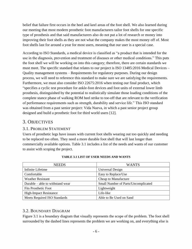
3.1. PROBLEM STATEMENT
Users of prosthetic legs have issues with current foot shells wearing out too quickly and needing
to be replaced too often. They need a more durable foot shell that will last longer than
commercially available options. Table 3.1 includes a list of the needs and wants of our customer
to assist with scoping the project.
TABLE 3.1 LIST OF USER NEEDS AND WANTS
NEEDS WANTS
Infinite Lifetime Universal Design
Comfortable Easy to Replace/Use
Weather Resistant Cheap to Manufacture
Durable – able to withstand wear Small Number of Parts/Uncomplicated
Fits Prosthetic Foot Lightweight
High-Impact Resistance Life-like
Meets Required ISO Standards Able to Be Used on Sand
3.2. BOUNDARY DIAGRAM
Figure 3.1 is a boundary diagram that visually represents the scope of the problem. The foot shell
surrounded by the dashed lines represents the problem we are working on, and everything else is
Page 12
- 7 -
a factor we must consider. The ground is an important component because our challenger will be
walking on it, and the surface could wear down the foot shell faster. We must also take the
prosthetic leg into account because much of the wear comes from the leg’s weight and contact
with the foot shell. The foot shell must also fit the prosthetic, so we need to ensure the sizing is
correct and it is relatively easy to put on.
FIGURE 3.1 BOUNDARY DIAGRAM FOR PROSTHETIC FOOT SHELL
3.3. QUALITY FUNCTION DEPLOYMENT (QFD)
The House of Quality, as shown in Appendix B, is part of a process known as Quality Function
Deployment (QFD). A QFD is used to define a customer’s specific needs and requirements,
turning them into specific plans. The House of Quality itself is a planning matrix that creates
relationships between all the working parts of a project and its specifications. There are seven
steps to creating a house of quality: Who, What, Who vs What, Benchmarking, How, How vs
What and How much. Each step can be found in the matrix in Appendix B.
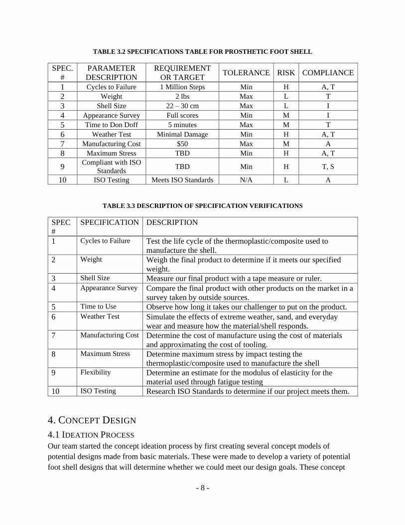
Table 3.2 summarizes the chosen specifications and their requirements for our foot shell. The
specifications listed were chosen using our House of Quality. We then assigned a high (H),
medium (M) or low (L) risk factor to each specification, determining how difficult we believe it
will be to achieve it. Finally, a compliance qualification was chosen based on how we’d
determine if our design meets the specification: analysis (A), inspection (I), similarity to existing
designs (S) and testing (T). Table 3.3 lists the testing methods associated with each specification
in Table 3.2.
Page 13
- 8 -
TABLE 3.2 SPECIFICATIONS TABLE FOR PROSTHETIC FOOT SHELL
SPEC.
#
PARAMETER
DESCRIPTION
REQUIREMENT
OR TARGET TOLERANCE RISK COMPLIANCE
1 Cycles to Failure 1 Million Steps Min H A, T
2 Weight 2 lbs Max L T
3 Shell Size 22 – 30 cm Max L I
4 Appearance Survey Full scores Min M I
5 Time to Don Doff 5 minutes Max M T
6 Weather Test Minimal Damage Min H A, T
7 Manufacturing Cost $50 Max M A
8 Maximum Stress TBD Min H A, T
9 Compliant with ISO
Standards TBD Min H T, S
10 ISO Testing Meets ISO Standards N/A L A
TABLE 3.3 DESCRIPTION OF SPECIFICATION VERIFICATIONS
SPEC
#
SPECIFICATION DESCRIPTION
1 Cycles to Failure Test the life cycle of the thermoplastic/composite used to
manufacture the shell.
2 Weight Weigh the final product to determine if it meets our specified
weight.
3 Shell Size Measure our final product with a tape measure or ruler.
4 Appearance Survey Compare the final product with other products on the market in a
survey taken by outside sources.
5 Time to Use Observe how long it takes our challenger to put on the product.
6 Weather Test Simulate the effects of extreme weather, sand, and everyday
wear and measure how the material/shell responds.
7 Manufacturing Cost Determine the cost of manufacture using the cost of materials
and approximating the cost of tooling.
8 Maximum Stress Determine maximum stress by impact testing the
thermoplastic/composite used to manufacture the shell
9 Flexibility Determine an estimate for the modulus of elasticity for the
material used through fatigue testing
10 ISO Testing Research ISO Standards to determine if our project meets them.
4. CONCEPT DESIGN
4.1 IDEATION PROCESS
Our team started the concept ideation process by first creating several concept models of
potential designs made from basic materials. These were made to develop a variety of potential
foot shell designs that will determine whether we could meet our design goals. These concept
Page 14
- 9 -
models were then narrowed down to eight realistic designs that were evaluated based on three
main functions for the foot shell: that it fits the prosthesis, protects the prosthesis, and is easy to
manufacture. The foot shell will almost always be worn while our user has shoes on, so this
narrows down our design focus. These main functions were broken down into several sub-
functions which were analyzed for each of the eight designs in Pugh matrices, which are shown
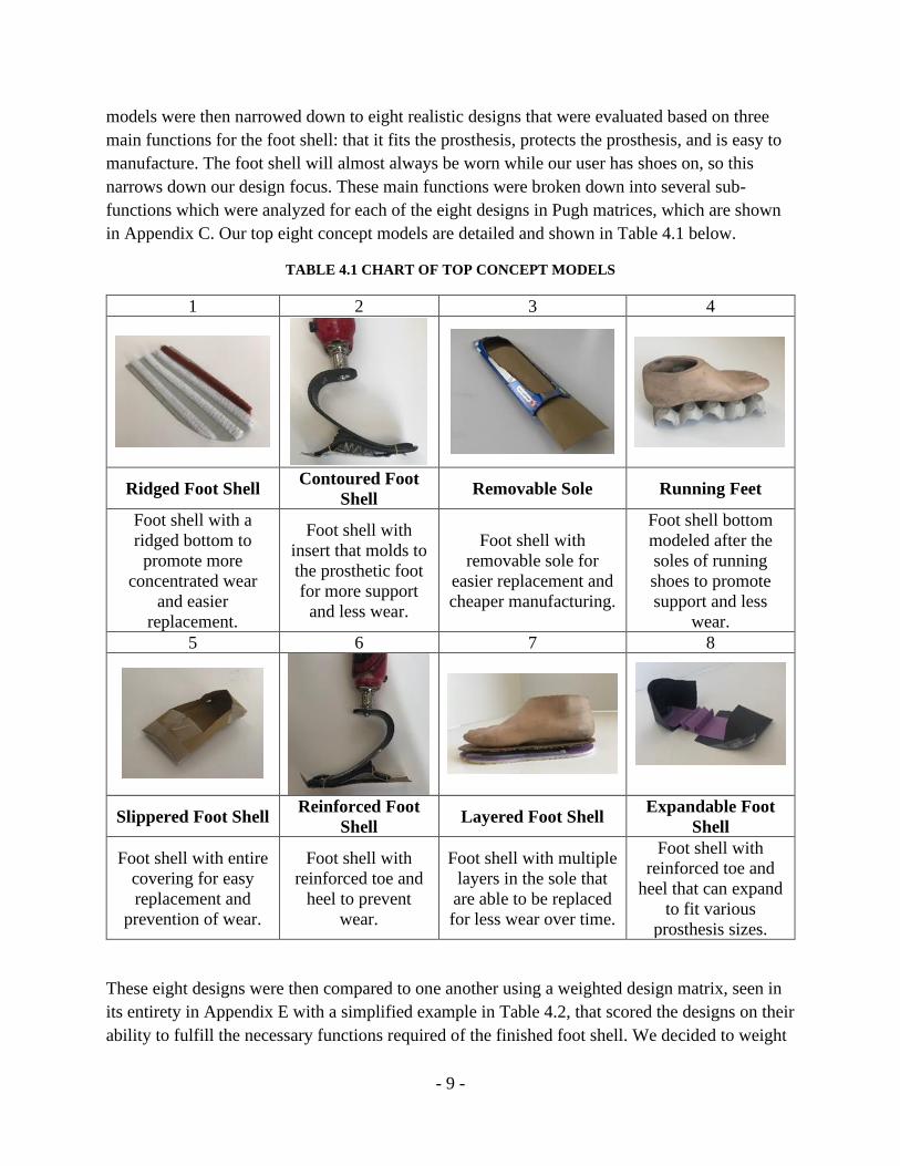
in Appendix C. Our top eight concept models are detailed and shown in Table 4.1 below.
TABLE 4.1 CHART OF TOP CONCEPT MODELS
1 2 3 4
Ridged Foot Shell Contoured Foot
Shell Removable Sole Running Feet
Foot shell with a
ridged bottom to
promote more
concentrated wear
and easier
replacement.
Foot shell with
insert that molds to
the prosthetic foot
for more support
and less wear.
Foot shell with
removable sole for
easier replacement and
cheaper manufacturing.
Foot shell bottom
modeled after the
soles of running
shoes to promote
support and less
wear.
5 6 7 8
Slippered Foot Shell Reinforced Foot
Shell Layered Foot Shell
Expandable Foot
Shell
Foot shell with entire
covering for easy
replacement and
prevention of wear.
Foot shell with
reinforced toe and
heel to prevent
wear.
Foot shell with multiple
layers in the sole that
are able to be replaced
for less wear over time.
Foot shell with
reinforced toe and
heel that can expand
to fit various
prosthesis sizes.
These eight designs were then compared to one another using a weighted design matrix, seen in
its entirety in Appendix E with a simplified example in Table 4.2, that scored the designs on their
ability to fulfill the necessary functions required of the finished foot shell. We decided to weight
Page 15
- 10 -
the functions in order of importance as follows: long life, durable, comfortable, ease of use,
lightweight, meets ISO standards, affordable, high impact resistance, weather resistant, and
lifelike being the least important. It is most important that our foot shell covers the foot
prosthesis and lasts longer than modern foot shell in order for our product to satisfy our problem
statement. The foot shell being lifelike was determined to be the least important function of our
eventual design as it is the constraint that can be worked around the most. Using these new
weighted functions, we determined that the best design for our foot shell would be a mix of the
slippered and reinforced concepts as they had the two highest scores.
TABLE 4.2 WEIGHTED DECISION MATRIX
Concept: Total: % of Max Possible Score
Concept 1 "Ridged" 151 54.9%
Concept 2 "Contoured" 103 37.5%
Concept 3 "Removable Sole" 188 68.4%
Concept 4 "Running Feet" 141 51.3%
Concept 5 "Slippered" 260 94.5%
Concept 6 "Reinforced" 219 79.6%
Concept 7 "Layered" 166 60.4%
Concept 8 "Expandable 165 60.0%
4.2 CONCEPT PROTOTYPE
Our initial design concept combines the best qualities from the top two concepts determined
from the weighted design matrix, the slippered and reinforced foot shells. A model of this
concept design is shown in Figure 4.1. The heel and keel of the foot shell are reinforced by
adding extra, stiffer material on the bottom of the shell and we will also be increasing the
compliance of the foot shell by making it out of a more flexible material and enlarging the
opening into the foot shell. The final prototype will be manufactured using a casting process in
which our selected thermoplastic will be poured into a manufactured mold or molds. This casting
will then be removed from its molds and trimmed into its final form. The main unknown for this
concept was the material of the concept design as we will need to perform testing on several
different blends of thermoplastics before deciding on a final material.
Page 16
- 11 -
FIGURE 4.1 CONCEPT CAD MODEL
Our concept prototype was designed using our concept CAD model (Figure 4.1) and fabricated
using 3D printing as shown in Figure 4.2.
FIGURE 4.2 3D PRINTED CONCEPT PROTOTYPE
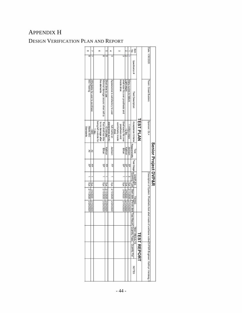
The main hazard associated with using our product will be the risk of falling and hurting the user
if the foot shell isn’t properly built or feels unnatural to walk on. We will most likely be working
with plastic molding and casting, and the proper safety measures must be followed depending on
what processes we use. The prosthetic foot is made of carbon and must be covered with a
protective sleeve to collect the carbon dust. The foot shell will also be exposed to the elements
such as dirt and water. It is important that the final design can perform in outdoor environments.
The design hazard checklist is attached in Appendix G.
Page 17
- 12 -
5. FINAL DESIGN
5.1 DESIGN DESCRIPTION
The final design, seen in Figure 5.1, makes some modifications to the concept models seen in the
previous section. Most notably, the larger mouth opening has been exchanged for a narrower
one that will more rigidly connect to the prosthesis. The interior cavity has also been sized to fit
with Dana’s prosthesis. The material used for the body of the foot shell will be a 40A durometer
urethane, and a tougher 70A durometer urethane will be used as reinforcement in the sole. The
interior of the sole is the main site for wear that causes the foot shell to fail, so using a stronger
material will resist more wear. The rest of the foot shell can be made of a less tough rubber so
that is more pliable, aiding the user in putting on and removing the shell. A shoe horn is
typically used for putting on and taking off foot shells, and this process will be made easier with
the more flexible layer of material near the opening.
FIGURE 5.1 FINAL DESIGN CAD MODEL
Figure 5.2 depicts a side view of the foot shell, which captures some of its complex geometry.
Foot shells from existing competitors offer lifelike solutions to their customers, and this product
should be no different. The increased detail of the toes will help to increase the lifelike feel of
the product, and the shell will be colored an appropriate shade to match the skin tone of the user
using a special dye for urethane rubber. We were able to model our foot shell so that the exterior
of the shell was able to fit inside of a size eight and a half shoe while also making sure that
Dana’s carbon fiber prosthesis will fit inside the interior cavity by using measurements taken
from his current foot shell.
Page 18
- 13 -
FIGURE 5.2 FINAL DESIGN CAD MODEL, SIDE VIEW
Figure 5.3, shown below, includes the interior cavity of the foot shell. The shape of this cavity is
designed to allow the prosthesis to rest on the keel (towards toes) and the heel of the shell while
providing enough rigidity to prevent the prosthesis from moving around in the shell.
FIGURE 5.3 FINAL DESIGN CAD MODEL WITH INTERIOR VIEW
The decision to use a 40A durometer urethane as the main material was based on previous senior
project groups that used similar durometers for foot shells, mainly the Vida Nueva low cost
Prosthetic Foot. Before ordering material, we looked at several samples of urethane ranging
from very soft to very hard. Based on the similarity to the hardness of Dana’s existing foot shell,
we decided that a 60A urethane would be tougher than the existing shell while also not being
over rigid, which could cause discomfort.
The geometry of the foot shell is very similar to existing foot shell designs. Most foot shells are
designed to be realistic, so this design uses a realistic model of the foot as a basis as well. The
geometry is also influenced by Dana’s shoe size, which restricts how large the exterior
Page 19
- 14 -
dimensions of the foot shell can be. The interior geometry is based on the size of the prosthesis
that Dana uses and is designed to be a relatively close fit in order to keep things from sliding or
moving inside of the shell. All drawings of the foot shell design can be found in Appendix O.
Because foot shells are made from molded plastics, performing any repairs on a foot shell is
difficult and buying a new foot shell is the likely solution for customers. This means that the
product must be durable in all respects to ensure that the entire shell lasts until the sole is
inevitably worn through. Users can increase the lifespan of their foot shells by always using a
cover sock over the prosthesis, which helps eliminate some of the shearing forces that are seen
when the prosthesis is directly in contact with the shell. The cover sock also helps eliminate
some of the shearing forces that cause the foot shell to wear down, which will help increase the
lifespan of the product. Once the foot shell has worn through the bottom, it is no longer a usable
product, and could inhibit the users’ ability to walk while wearing the foot shell. It is
recommended that the user checks the condition of their foot shell before use, specifically feeling
for any thinning of the sole occurring at the heel and keel.
The safety of the foot shell design is also impacted by how much wear is done to the shell while
being used. Shells that are worn out and have holes in the sole will be more susceptible to
damage from outside sources such as moisture and particulates. Due to the complex profile and
surfaces associated with the foot shell design, we were unable to run any successful finite
element analysis simulations by simulated forces acting on foot shell during use. The forces
acting on the foot shell by the carbon fiber prosthesis and ground consist of many different
components with many different magnitudes, which will be too complex to model using the tools
available to us. We will also be unable to successfully estimate the magnitude of the forces
acting on the foot shell as they will change depending upon several factors: the angle of contact
between the shell and ground, the type of ground material, the type of activity being performed
by the user, and the force applied by the carbon fiber prosthesis (which would require analyzing
the prosthesis as well).
A summary cost analysis for each of the design sub-assemblies can be found in Table 5.1 with a
full budget analysis in Appendix I and an indented bill of materials in Appendix J, this table
summarizes the cost for material procurement that is required to manufacture each sub-assembly.
Page 20
- 15 -
TABLE 5.1 SUMMARY COST ANALYSIS
SUB-ASSEMBLY COST SOURCE
Shell Assembly $55.56 Smooth-On
Urethane Mold $128.32 Smooth-On
Mold Box Assembly $68.54 Home Depot
3D Printed Negative N/A QL+
Total: $252.02 Budget = $1000
5.2 DESIGN JUSTIFICATION
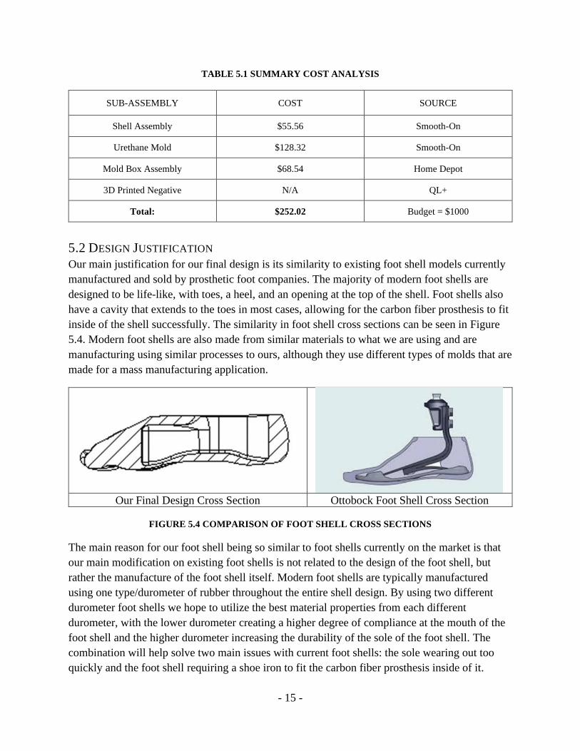
Our main justification for our final design is its similarity to existing foot shell models currently
manufactured and sold by prosthetic foot companies. The majority of modern foot shells are
designed to be life-like, with toes, a heel, and an opening at the top of the shell. Foot shells also
have a cavity that extends to the toes in most cases, allowing for the carbon fiber prosthesis to fit
inside of the shell successfully. The similarity in foot shell cross sections can be seen in Figure
5.4. Modern foot shells are also made from similar materials to what we are using and are
manufacturing using similar processes to ours, although they use different types of molds that are
made for a mass manufacturing application.
Our Final Design Cross Section Ottobock Foot Shell Cross Section
FIGURE 5.4 COMPARISON OF FOOT SHELL CROSS SECTIONS
The main reason for our foot shell being so similar to foot shells currently on the market is that
our main modification on existing foot shells is not related to the design of the foot shell, but
rather the manufacture of the foot shell itself. Modern foot shells are typically manufactured
using one type/durometer of rubber throughout the entire shell design. By using two different
durometer foot shells we hope to utilize the best material properties from each different
durometer, with the lower durometer creating a higher degree of compliance at the mouth of the
foot shell and the higher durometer increasing the durability of the sole of the foot shell. The
combination will help solve two main issues with current foot shells: the sole wearing out too
quickly and the foot shell requiring a shoe iron to fit the carbon fiber prosthesis inside of it.
Page 21
- 16 -
5.3 DESIGN CHANGES SINCE CDR
There are a couple of critical changes that were implemented into the design after the CDR stage.
The primary change was to the material being used for the bottom/sole portion of foot shell, with
the 60A urethane being upgraded to a 70A urethane instead. We determined this change by
conducting durometer testing on a current foot shell provided to us by our sponsor; the results of
the testing showed that the bottom of the current foot shell was already a higher durometer than
60A. These results meant that using a 60A urethane in the new design would not improve the
hardness of that area. We then decided to replace this urethane with one with a 70A durometer
rating instead; this way the sole area of the foot shell can have a higher hardness than current
models.
Another key change to the design of the foot shell was in the design of the mold as the
surrounding mold material would need to be made from a urethane rubber instead of a silicone
rubber. During the initial manufacturing phase, we discovered that using a silicone mold when
casting a urethane part results in the urethane part curing with a highly tacky surface finish which
is not ideal for a full-size foot shell. Due to the different chemical makeup of the two types of
rubber, the two rubbers started to partially bond during the curing process and the finished
casting did not come out cleanly. By using urethane instead of silicone, the urethane parts come
out cleanly and the cost of the mold is reduced due to the urethane rubber being less expensive to
acquire from Smooth-On than the silicone rubber we were previously planning on using.
6. MANUFACTURING
This section has been updated to discuss the materials and manufacturing processes that were
necessary to create the final product.
6.1 PROCUREMENT
Our procurement process began by contacting Reynold’s Advanced Materials, a third-party seller
that acted as a middle-man between us and Smooth-On materials, the manufacturer of the
urethane rubbers that we will be using. We initially purchased three types of urethane rubbers of
three different durometer ratings, Vytaflex 40A, 50A, and 60A, one silicone rubber, MoldMax
40A, and a can of mold release agent spray. Due to our issues casting with the MoldMax
silicone, previously discussed in section 5.3, we decided to replace the MoldMax 40A with a
larger quantity order of Vytaflex 40A urethane rubber. After initial testing was conducted using
our acquired materials, we decided to order PMC 770 urethane to replace the Vytaflex 60A,
which was originally planned for the bottom layer of the foot shell. The durometer test showed
the 60A urethane would not have improved the hardness of the foot shell compared to current
models used by our challenger. In the same order as the new 70A urethane, we also ordered a
dye to be used to keep both layers of the foot shell a similar color.
To procure the materials for our mold box, we traveled to Home Depot and purchased two sheets
of acrylic measuring 18” x 24” x ¼” and a tube of silicone based plastic adhesive sealant. The
Page 22
- 17 -
acrylic sheets were purchased as they would be easy to machine to size and allow the molding
process to be fully visible. The silicone adhesive was purchased in a size that could be used in a
caulking gun to make the application process smooth and accurate.
The only part of our molding process that we did not purchase was the 3D printed negative,
which we acquired by utilizing a 3D printer in the on-campus QL+ lab. This 3D printer printed
the foot shell in PLA plastic and all the necessary support material in a cornstarch-based water-
soluble material. This way there were no remnants of the support material left on the finished
part.
Our team’s initial budget, set by QL+, was $1000. As shown in Appendix I, our project fell
under budget at close to $396. The most expensive components of the project were the rubber
materials purchased from Reynolds Advanced Materials.
6.2 INITIAL MANUFACTURING PLANS
We began with three possible manufacturing plans for creating our prosthetic foot shell which
depended upon how the two halves of out foot shell would bond together. Since both of our foot
shell halves were made of urethane rubber, they bonded together easily. According to the
Smooth-On website, newly mixed rubber bonds to cured rubber so long as the rubber has not
been fully cured. The chances for a lasting bond between the two rubbers decreases significantly
the longer the rubber cures for. Due to the long cure times for our selected urethane rubbers -
sixteen to twenty hours - it was key to pour the new layer of rubber onto the curing rubber at the
right moment for the bond to have the best chance of forming.
6.2.1 MANUFACTURING PLAN 1
Our first choice for our manufacturing plan was to use one mold that ultimately formed the foot
shell with a horizontal parting line. We would pour the bottom layer of the foot shell with a high
durometer urethane rubber, let this layer partially cure, and then fill the remainder of the mold
with the lower durometer urethane. The two urethane layers would bond together chemically and
naturally at the end of the top layer’s curing process.
6.2.2 MANUFACTURING PLAN 2
Our second choice was to use two separate 3D negatives, each representing one half of the foot
shell. We would then create two molds, one for each of the negatives. The two printed halves
would need to be cast individually using the mold box, resulting in four mold halves.
6.2.3 MANUFACTURING PLAN 3
A third manufacturing plan was to suspend the 3D printed foot shell in clay and pour silicone
over the clay to create the top half of the mold. After this top layer of silicone was done curing,
the mold box would be flipped over so that the clay can be removed and replaced with more
silicone, forming the bottom half of the mold. This would allow for the manufacturer to control
where the parting line is on the mold based on where the 3D printed negative sits in the clay
prior to the initial silicone pour. We ended up choosing this method as it was the most
Page 23
- 18 -
straightforward approach. This method also allows us to control the placement of the parting line
directly which would avoid having to make a blind cut into the mold. A simplified list of steps
can be seen in the Operator’s Manual in Appendix N.
6.3 MANUFACTURING THE MOLD BOX
We began our chosen manufacturing process by building the mold box that we used to hold our
urethane mold while it cured around our 3D printed negative. This mold box was built using
acrylic sheets we purchased. The sheets were sawed into the correct dimensions, ultimately
creating a box with a height of four inches, width of nine inches, and length of 18 inches. Using
quick release clamps, we secured the edges of the acrylic sheets together. We then bonded the
edges of our mold box together using a silicone-based gel plastic adhesive that also served as a
sealant.
FIGURE 6.1 FINAL ASSEMBLY OF MOLD BOX
6.4 CREATING OUTER FOOT SHELL MOLD
Using the scaled 3D printed mold negative that mimicked the final foot shell prototype, we
casted our urethane mold by forming a layer of modeling clay at the bottom of the box,
embedding the 3D printed part in it, and creating a parting line using the modeling clay. We then
created four small holes in the clay on each of the four corners of the box to create keys so the
final pieces would fit together correctly. Mold Release Agent was sprayed over the clay and
inside the cavity of the 3D model, and then VytaFlex 40A urethane rubber was poured over the
mold. The parting line of the urethane mold could not be very complex, so we created a
simplistic horizontal plane to pour the mixed urethane on top of the cured urethane effectively.
Page 24
- 19 -
FIGURE 6.2 MOLD BOX ASSEMBLY WITH 3D PRINTED FOOT SHELL EMBEDDED IN CLAY
FIGURE 6.3 MOLD BOX ASSEMBLY WITH BOTTOM LAYER OF URETHANE RUBBER
Before pouring the top layer of the lower durometer urethane, the bottom layer of urethane
needed to cure fully to prevent bonding to the previous layer. To make this process possible, we
waited approximately 24 hours to check in on the urethane to pour the newly mixed urethane.
The mold box was flipped, the clay removed, and two columns of modeling clay were placed on
the PLA to create sprues to give us a place to pour the inner urethane rubber and allow air to
Page 25
- 20 -
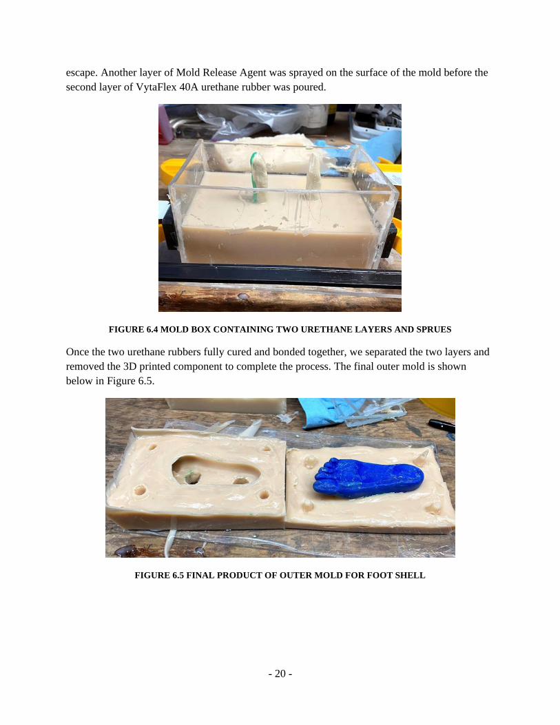
escape. Another layer of Mold Release Agent was sprayed on the surface of the mold before the
second layer of VytaFlex 40A urethane rubber was poured.
FIGURE 6.4 MOLD BOX CONTAINING TWO URETHANE LAYERS AND SPRUES
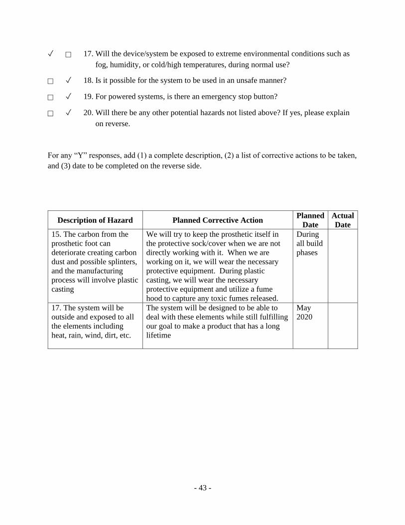
Once the two urethane rubbers fully cured and bonded together, we separated the two layers and
removed the 3D printed component to complete the process. The final outer mold is shown
below in Figure 6.5.
FIGURE 6.5 FINAL PRODUCT OF OUTER MOLD FOR FOOT SHELL
Page 26
- 21 -
The mold assembly for this manufacturing plan is shown below in Figure 6.6.
FIGURE 6.6 PRIMARY MANUFACTURING PLAN MOLD ASSEMBLY
During each of these processes, we will have to spray Smooth-On Mold Release Agent before
pouring the urethane in its respective molds. This release agent coats the mold box, 3D printed
negative, and urethane mold which allows for the parts of the mold to be easily parted from one
another. This step is especially important for making the urethane mold as we want to minimize
the risk of it tearing. We will also need to include parting lines and sprues when casting our
silicone mold to make the molding and urethane casting processes much easier, with the parting
line separating the mold in two pieces to avoid cutting the mold blindly and the sprue allowing
the mold to be filled without separating the two mold halves.
6.4.1 INITIAL TESTING PROCEDURES
We were able to test the bonding between the urethane rubbers by casting a spare block of
aluminum in 60A urethane. We began by spraying a Tupperware container (which was used as a
mold box) and our aluminum model with Mold Release Agent, before pouring MoldMax 40A
silicone over the aluminum block, which was suspended using four short round wooden dowel
rods (Figure 6.7). We then removed the silicone mold from the rudimentary mold box and the
aluminum part from the silicone, which left us with a singular cavity mold.
Page 27
- 22 -
FIGURE 6.7 TEST SILICONE MOLD ASSEMBLY
Using this silicone mold, we then casted a replica of the aluminum block using Vytaflex 60A
urethane rubber. We chose this specific rubber to better understand the different material
properties when increasing the durometer of the plastic. This casting process is depicted in
Figure 6.8. Any other observations made during this test process are discussed in section 8.2
Planned Analysis, Testing, and Purchasing.
FIGURE 6.8 TEST URETHANE CASTING
Page 28
- 23 -
6.5 CREATING THE FINAL FOOT SHELL
To create the final foot shell model, we began by putting the two layers of our outer mold
together, making sure the keys aligned with one another. Weights were then set on top to prevent
leaking.
FIGURE 6.9 OUTER MOLD PUT TOGETHER WITH WEIGHTS ON TOP
The two parts of the VytaFlex 50A urethane rubber were mixed and carefully poured into one of
the sprues until the inner cavity was around halfway filled. As mentioned earlier, VytaFlex has a
1A:1B weight ratio. Part B was measured first, then a drop of the dye was added and the two
were mixed thoroughly before adding Part A. We waited approximately 1 hour, ensuring the
layer had cured slightly but remained tacky, before pouring the second layer of PMC 770A into
the sprue. The PMC 770A urethane rubber has a 2A:1B weight ratio, so we carefully measured
the two parts on a scale before adding a drop of the dye to Part B and mixing. After 24 hours, to
make certain the two layers had cured fully, the two components were carefully separated, and
the final foot shell was removed.
Page 29
- 24 -
FIGURE 6.10 POURING THE PMC 770A INTO THE OUTER MOLD
FIGURE 6.11 FINAL SCALE MODEL OF FOOT SHELL
6.6 3D PRINTED COMPONENTS
Since no members of our group own a 3D printer or have free access to a high-quality surface
finish 3D printer, we would need give the stereolithography file (STL file) of our prosthetic foot
shell to an outside source to print for us. We specifically used the polylactic acid thermoplastic
(PLA) 3D printer at the QL+ student association laboratory on the Cal Poly campus since it has a
higher quality surface finish than other printers available to us on campus. Surface finish is
important for our 3D printed negative because a bad surface finish would be transferred from the
negative to the urethane mold, and then to the final casted part. A poor surface finish would
diminish the lifelike quality that the foot shell must have. Furthermore, a rougher surface finish
will also affect how the shell interacts with the carbon fiber prosthesis.
Page 30
- 25 -
Another benefit of using the QL+ printer is the support material used during the printing of the
part. Other printers that we could use have the same material used for support material as the part
itself, meaning the support material must be broken and filed off the printed model. The 3D
printer used by QL+ uses a type of support material that is water soluble, so we do not not have
to mechanically remove the support material from the part. The less support material that needs
to be mechanically removed from the part, the lower chance there is for the part to be damaged
during the process.
Once we were sure our chosen manufacturing process worked correctly, we were going to
outsource the print of a full-scale mold negative to use for creating the outer mold of the foot
shell. However, due to the circumstances of the project, we were unable to complete this portion.
6.7 CHALLENGES
Our team faced many challenges during the manufacturing of our foot shell. One of the major
challenges we faced was selected compatible materials. We began by using a silicone rubber for
the outer mold and urethane rubber for the inner mold. After a few tests, we found that our
urethane rubber was not curing fully and remained tacky, even after curing for over 24 hours.
After proposing various explanations for this including temperature and uneven mixing, we
ended up calling Reynolds Advanced Materials. A representative spoke to us and told us that
silicone rubber and urethane rubber are not compatible materials and would never cure fully if
put together. After the representative’s recommendation, we switched to using only urethane
rubber for both the outer and final foot shell mold. This switch solved our issue and the molds
were able to fully cure.
Another challenge we faced was the many air bubbles that formed in our final product. This was
an issue because we believed it could lead to the earlier degradation of our foot shell. It also
contributed to a poor surface finish for the final model. We mitigated this challenge by practicing
various pouring techniques. Pouring slowly and from high above the surface of the mold in one
spot reduces the amount of air bubbles formed. It is also helpful to mix the two parts of the
urethane rubber slowly, avoiding whipping the mixture.
6.8 RECOMMENDATIONS
For future production, we highly recommend remaining consistent with the rubber material
chosen, whether it be silicone, urethane, etc. We also suggest becoming familiar with the
different pouring techniques to create a smooth surface finish with minimal air bubbles. It is also
important to coat each part thoroughly with the release agent when creating the outer mold,
especially in the cavity of the 3D printed negative. This ensures the two components do not stick
together and are able to be removed easily. Furthermore, each part takes around one day to
complete, so it is crucial to time the pours in advance to have enough time to finish all the parts
in the desired timeframe.
Page 31
- 26 -
7. DESIGN VERIFICATION
This section discusses how our team confirmed that our final foot shell met all our design
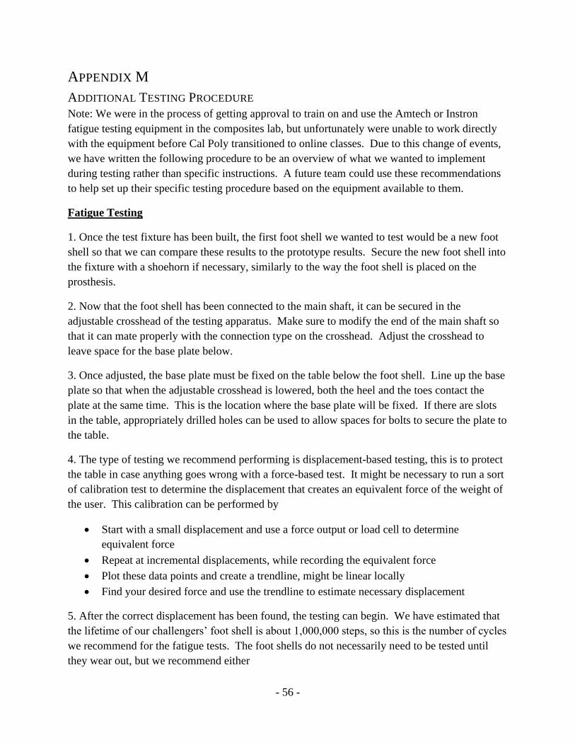
specifications. These specifications are listed along with the corresponding tests, test results, and
recommendations for a final design. The full Design Verification Plan & Report can be found in
Appendix H.
7.1 SPECIFICATIONS AND TESTS
7.1.1 CYCLES TO FAILURE
We expect our final product to have infinite life; therefore, we concluded it must reach at least
3.6 million steps to failure. This specification was determined by assuming our user takes 10,000
steps a day which equates to 3,650,000 steps/year. We will test this specification using a custom-
built fixture on an Instron in the Cal Poly Composites Laboratory. This fixture will need to
produce a shearing movement within the foot shell to mimic the steps a person would take when
walking on it. We are in the process of designing this fixture and will need to manufacture it
before our model is finalized.
7.1.2 WEIGHT
The foot shell must be lightweight as our user will be wearing it for extended periods of time.
We estimate that the final product must be less than two pounds for it to be comfortable to wear.
This can be tested by placing our final design on a scale and determining its total weight. We can
also verify that this weight is satisfactory for our user by having him try on the foot shell.
7.1.3 FIT
The foot shell must also properly fit over the prosthesis for it to function correctly. This
requirement is met by increasing the opening of the foot shell and creating the upper material out
of a lower durometer urethane rubber so it can stretch over the prosthesis. The foot shell must
also fit inside of our user’s shoe. He wears a men’s size 8.5, so given the shell fits inside of a
shoe that size, we will meet our specification.
7.1.4 APPEARANCE
The final appearance of our product must be satisfactory to our user. We expect it to look as life-
like as we can make it. This requirement will be fulfilled by creating an appearance survey and
giving it out to a multitude of people, including our user. Full marks on our survey from a
majority of the group will result in us passing this specification test.
7.1.5 TIME TO USE
We want our final product to be relatively easy to use, and a large portion of the usability comes
from the time taken to put on and take off the foot shell. We estimate that a don doff time of less
than 2 minutes will fulfill our expectations.
Page 32
- 27 -
7.1.6 WEATHER RESISTANT
Most of the time, our user will be wearing the foot shell inside of his shoe. However, we want to
ensure our design will not fail when exposed to the elements. This means that minimal damage
must occur when left to variable weather conditions. We determine its resistance by leaving the
foot shell outside over the course of several days to weeks to evaluate how it will be affected.
7.1.7 TOTAL COST
We want to make sure that our final product is able to be produced consistently and has
reasonable manufacturing costs. This allows future users to readily purchase a new foot shell
when their old one inevitably fails. After looking at our costs and comparing them to those of
other manufacturers, we estimate a price of less than $50 per foot shell while still making a profit
is sufficient.
7.1.8 ISO TESTING
According to ISO Standards, foot shells are considered a medical device. This means that there
are strict requirements we must meet in order for it to be sold to users. We need to make sure that
our final design meets all the associated ISO standards. This will be done by comparing our final
product to the standards and ensuring there are no gaps between the two and using the testing
standards as guidelines for how we perform our tests.
7.2 COMPLETED TESTING
The two main tests that we were able to complete before transitioning to online classes were
durometer testing and testing cure times to maximize adhesion between layers. The durometer
testing was performed to compare the hardness of our challengers’ foot shell to the hardness
values of rubber samples we wanted to use for the sole layer of the foot shell. The hardness
values of the rubber samples we ordered were advertised as Shore A hardness values, but we
only had access to a Shore 00 durometer tester. Shore 00 is traditionally used to measure the
hardness of softer materials. The values for hardness were converted from 00 to A to keep the
results consistent. The results of the durometer testing are tabulated below.
TABLE 7.1 DUROMETER TESTING RESULTS IN SHORE 00 AND SHORE A EQUIVALENT
Material Shore 00 Hardness Shore A Equivalent
Vytaflex 40A 84.5 37.5
Vytaflex 50A 88 45
Vytaflex 60A 92 57.5
Foot Shell 86-94 40-65
Our original design called for the sole of the foot shell to be made from a durometer 60A
urethane and the rest of the material to be a durometer 40A urethane. We found that the hardest
areas of the foot shell sole had a Shore A hardness of 65, meaning that we would need to change
the material used in the sole if we wanted to use a harder material than what is currently used in
Page 33
- 28 -
products. Shortly afterwards we purchased new material for the sole, PMC 770, which has an
advertised Shore A hardness of 70. While we wanted to perform durometer testing on the PMC
770 samples, we were unable get a sample ready in time. The more pliable material on the foot
shell had a hardness value of 40A, which is very close to the hardness of the Vytaflex 40A.
The other main testing performed was finding the optimal waiting time between pouring layers
of urethane to maximize the adhesion between them. Tests were performed at intervals of one
hour up to six hours, and after being allowed to cure for 24 hours, samples were pulled and pried
apart to see if the layers would stick together. At one hour, we found that the boundary layer
between the two rubbers was less well-defined as the top layer was introduced before any curing
could occur, creating a less consistent connection. At six hours, the bottom layer had cured too
much before the second layer was poured on top, creating little adhesion between the two. We
found that waiting for two hours after the first pour created the strongest connection between the
layers and was unable to be pulled apart by hand. While tests for 3 and 4 hours created samples
that did stick together, they were able to be pulled apart by hand and peeled off the bottom layer.
This test helped us figure out the optimal time to wait between pouring the two layers of rubber
for the prototype.
FIGURE 7.1 INCOMPLETE ADHESION WHEN BOTTOM LAYER CURED TOO LONG
Page 34
- 29 -
7.3 FUTURE TESTING
The main testing initially planned for the project was fatigue testing to directly compare the
cycles to failure for our prototype to preexisting designs. This testing was planned for the
beginning of Spring Quarter, which was moved online shortly after the situation with COVID-19
escalated. Because of these changes, plans were put in place to help a future group complete this
testing if the project were to be picked up again in the future. These plans include an overview
of the testing procedure our group wanted to perform, a possible design for a test fixture, and an
overview of manufacturing for the selected test fixture. An overview of the test fixture and
testing procedure will be included here, with more detailed information attached as appendices.
7.3.1 TEST FIXTURE
FIGURE 7.2 POSSIBLE FATIGUE TEST FIXTURE DESIGN, INCLUDING BASE PLATE
The test fixture design is meant to imitate the shape of a prosthetic foot to create similar
conditions for wear to happen. Like an actual prosthetic foot, the foot shell may need to be
secured on the two blades using a shore horn or similar device to make it easier to put on. The
current design uses a design that makes it easy to replace the blades if necessary. The fixture is
also accompanied by a base plate, which will be fixed to the table below the main shaft and
serves as the surface that the foot shell will be pushed against. Because of the angled surface
that the foot shell interacts with, the corner of the blade will push against the foot shell sole,
which is the main factor contributing to the wearing down of the foot shell. Appendix K
includes steps for manufacturing the test fixture.
Page 35
- 30 -
FIGURE 7.3 STRESS DISTRIBUTION SEEN ON BOTTOM OF TEST FIXTURE BLADES
The test fixture was run through FEA tests to determine the functionality of the design. The
main finding of the FEA shows that the protruding blades see high levels of stress that will need
to be monitored over the course of fatigue testing. The blades can be easily replaced if necessary
but can cause inconsistency in the results if changed out during an uncompleted test. Included in
Appendix L is a more detailed look at the results of the FEA.
7.3.2 TESTING PROCEDURE
If this project is continued at Cal Poly, the fatigue testing will likely take place in the composites
lab, which has access to both Instron and Amtech fatigue testing equipment. The main fatigue
tests will be performed on several prototypes, and additionally on a new foot shell identical to
the one currently worn by our user. All foot shells will be tested for 1,000,000 cycles which is
the number of cycles we estimate our users foot shells currently last in his experience, or until
failure when the test blade pierces completely through the sole. Numerical data will be collected
directly from the testing software, and qualitative results will be taken between test sessions and
after test completion to describe the condition of the foot shell at various steps through the
products life. The main goal of the fatigue testing is to create a prototype foot shell that has a
longer life than the purchased foot shell. Appendix M includes instructions for the testing
procedure our team was hoping to perform for this project. Also included in Appendix M are
recommendations for giving a prototype to our challenger for a fit and direct use test.
8. PROJECT MANAGEMENT
The design process for the project started with background research and defining the problem
posed by the sponsor. Next, the scope of the project, via a scope of work document, was planned
out and sent to the sponsor. We then determined the details of the design and reviewed said
details through a preliminary design review document. Our design was finalized and prepared for
manufacture using the critical design review document. We then began our manufacturing
Page 36
- 31 -
process as described in section 6 of this report. Testing of our foot shell prototype began around
the same time as we began finalizing the manufacturing process. Unfortunately, due to the onset
of the COVID-19 pandemic, the team was unable to fully complete the manufacturing and
testing stages of this process and was forced to modify our process. Our manufacturing process
was able to be fully completed with a half-size model of our foot shell but not with a full-size
negative due to our group not having access to the same 3D printer that we used to print the half-
size model. We initially planned on outsourcing the 3D printing to a third party, but we were
unable to due to many companies being closed during the pandemic and a lack of time needed
for us to send them our CAD file and for them to ship the 3D printed part back to us.
Our testing phase was greatly impacted by the coronavirus shutdown as we were unable to
manufacture our testing fixture or access the machines required to fully test our foot shell. The
testing we were able to complete successfully included durometer testing of current foot shells
and our purchased urethane rubbers, testing to determine a proper cure time between the two foot
shell layers, and a simulated finite element analysis on our proposed test fixture, all of which
were previously described in section 7.
Although we were unable to finish our design process as planned, we made significant progress
in the manufacturing of our foot shell and are now able to set a strong starting point for a future
team to continue this project in the future. We feel that the first stages of the design process went
very well aside from the many phases of ideation and brainstorming that our design went
through. Due to the nature of the project being an improvement of an existing product and design
we could have simply started our product design by modifying the existing design of foot shells
instead of conceptualizing a new design from the ground up. If this phase of project design had
been sped up, we would have been able to spend more time improving our manufacturing
process and been able to develop a verification prototype faster. In the future, starting the
manufacturing and testing processes sooner would have allowed us to generate more test castings
of our foot shell using our determined manufacturing plan.
9. CONCLUSION
9.1 PROJECT REFLECTION
Our project was as successful as it could be given the constraints put on the team during the final
quarter of work. Our first two quarters of work went very smoothly, if a little slow due to the
long period of time spent working on ideation for our foot shell design. The project
manufacturing process was very successful as our sponsor was able to mail our previously
acquired materials to one of our team members sheltering at home. Our final design was also
successful as it was modeled against a prosthetic foot that our challenger currently used but was
able to give us. One area of our project that was not as successful was the testing of the foot shell
and our various prototypes. We were only able to perform minimal testing of our test castings
because by the time we were able to begin testing, all of the required testing equipment we
needed were unavailable for us to use. This lack of testing means that our foot shell, though it
Page 37
- 32 -
was designed and manufactured to the best of our ability, may not be meeting the design
constraints that we initially designed the foot shell to meet. Without this testing, it is unclear if
the foot shell achieved its primary goal of being more durable than shells currently available on
the market. We were also unable to fully manufacture the foot shell and only manufactured a
half-size model of the shell. We are still unsure if our manufacturing method will scale up to a
full-size model without any molding deficiencies like air bubbles, cracks, or low surface finish
quality.
Our project was able to achieve many goals we had not originally intended to design towards, as
our foot shell was able to be manufactured in the garage of one of our team members without
requiring factory machinery or molding processes. Additionally, our foot shell is more
customizable than other foot shells on the market due to its multiple layered design. These layers
can be made using any two compatible urethane rubbers of any durometer, dependent upon user.
Our team was also able to work very well together despite the coronavirus shutdown and was
able to produce a verification prototype that will be useful for any teams that continue this
project in future quarters. Our verification prototype also achieved its goals by having a realistic
design as well as successful usage of dyes to make both layers a common skin tone. The foot
shell prototype was also able to be manufactured without separation between layers of the foot
shell, meaning that the two urethane rubbers were able to bond naturally during the
manufacturing process.
If we were to perform this project again, the main changes we would make revolve around the
timing of our project. We would spend less time on the design iteration phase as our project was
primarily an improvement on an existing foot shell design. Instead of trying to design a new foot
shell from the ground up by trying to make it expandable or minimalistic, we could have saved
time by simply taking a current foot shell design and modifying it slightly, which is ultimately
what we ended up doing. By speeding up this process, we would have been able to spend more
time perfecting our manufacturing process, especially the 3D printing of the foot shell negative
and casting of the mold. We would also spend more time researching specific brands of urethane
rubber and how they interact with each other, which might have prevented our unnecessary
purchase of silicone rubber that interfaced incorrectly with our urethane test parts. We also ran
into difficulty 3D printing our negatives due to improper communication with the representatives
of the QL+ student association, whose 3D printer we ended up using to print our foot shell
negatives. We would have also started talking to these representatives earlier so that way the
negatives could have been printed earlier and without as much difficulty, enabling the team to
begin our mold manufacturing earlier as well.
Overall, the project was very successful in developing a foot shell with the possibility of lasting
longer than the foot shells currently used by our challenger. Our half-size model was able to be
fully manufactured by one of our team members and displays many attributes that were
important to us as a team, such as a higher durometer sole and a flexible mouth. Even though we
Page 38
- 33 -
were not able to complete the project as planned, the progress we made on our project sets a
strong starting point for a future group to pick up where our group left off.
9.2 NEXT STEPS
Due to the coronavirus shutdown, there is still a fair amount of work that needs to be done in
order to deliver a full-size foot shell to our challenger. We would first recommend that a full-size
3D printed negative be printed using a 3D printer that is able to print support material out of a
material that can dissolve in either water or some other liquid like a weak base or acid, this way
the support material does not have to be ground off and potentially damage the part’s surface
finish. After the negative has finished printing, the full-size mold box will need to be built using
the same method discussed in the manufacturing section of this report. The acrylic sheets have
already been cut to the correct size by our team and would simply need to be assembled and
sealed using the silicone plastic adhesive. The foot shell mold and casted foot shell would be
manufactured using the same process previously described in section 6 of this report. However,
we recommend that the sponsor or next project team redesign the mold to include better
ventilation for the air bubbles that naturally form in the mold box. These improvements would
improve the surface quality of the foot shell, reduce porosity in the shell itself, and eliminate any
risk for large air bubbles in the foot shell.
Once the foot shell has been fully casted, testing can begin on the foot shell following the testing
procedures described in section 7. Testing is important as very minimal testing was conducted by
our project team prior to the COVID-19 pandemic. The most important test still left to conduct is
a cycles to failure test described in section 7.3; this test is important as the results from the test
would be directly compared to current foot shell models to see if our foot shell will last longer
than current shells on the market. Further lab testing may be conducted by the sponsor or future
project teams if deemed necessary by said parties. Another important test still needing to be
conducted would be an in-field test conducted by delivering the finished prototype to the QL+
challenger and having him wear the new shell for a predetermined period of time. Instructions
and guidelines for said test can be found in Appendix M. If the foot shell passes all of the tests
performed with the challenger, then any further steps, whether the shell is mass-produced or kept
by the sponsor, would need to be determined by the sponsor representatives themselves.
Page 39
- 34 -
10. REFERENCES
1. “The QL+ National Program Began.” QL+ CalPoly | Home, cpqlplus.com/.
2. “Energy Loss and Stiffness Properties of Dynamic Elastic Response Prosthetic Feet.:
JPO: Journal of Prosthetics and Orthotics.” Lippincott Williams & Wilkins Inc.,
September 2001
journals.lww.com/jpojournal/Fulltext/2001/09000/Energy_Loss_and_Stiffness_Propertie
s_of_Dynamic.11.aspx.
3. Jaarsveld, H. W. L. Van, et al. “Stiffness and Hysteresis Properties of Some Prosthetic
Feet - H. W. L. Van Jaarsveld, H. J. Grootenboer, J. De Vries, H. F. J. M. Koopman,
1990.” SAGE Journals, journals.sagepub.com/doi/abs/10.3109/03093649009080337.
4. Sayman, and Ozen. “Modeling and Stress Analyses of a Normal Foot-Ankle and a
Prosthetic Foot-Ankle Complex.” Acta of Bioengineering and Biomechanics, 2013
yadda.icm.edu.pl/baztech/element/bwmeta1.element.baztech-bff8b696-0990-45b5-9a6d-
e4bbd4b9b789;jsessionid=241116660A418F4420A33DE428153143.
5. Hahl, Taya, Saito. “Optimization of mass-produced trans-tibial prosthesis made of
pultruded fiber reinforced plastic.” Mechanical Engineering Research Laboratory,
Department of Mechanical Engineering, University of Washington, June 26, 2000.
6. Stills, Melvin L. “Partial Foot Prostheses/Orthoses.” American Academy of Orthotists
and Prosthetists, 1987. http://www.oandplibrary.org/cpo/pdf/1988_01_014.pdf.
7. Fillauer. “MCV Foot Shell.” Fillauer, fillauer.com/Lower-Extremity-
Prosthetics/cosmetic-solutions/MCV-foot-shell.php.
8. “Enviroshell - Breeze.” College Park, www.college-park.com/enviroshells-breeze.
9. “Foot Shells from Kingsley: Kingsley MFG Company: Orthotics & Prosthetics
Supplies.” Foot Shells from Kingsley | Kingsley MFG Company | Orthotics & Prosthetics
Supplies, www.kingsleymfg.com/KMFGStore/Catalog_Product.asp?dept_id=7F805A57-
C6A2-479E-8D92-513D5587D77D&product_id=KFSHELL.
10. “Praetor USA Rush Foot.” Patient Home |, Praetor USA, rushfoot.com/patient-home/.
11. Robinson, Matt. Personal interview. 24 October 2019.
12. Baker, Sarah M., et al. Low-Cost Prosthetic Leg for the Vida Nueva Prosthesis Clinic.
Mechanical Engineering Department, 2011, digitalcommons.calpoly.edu/mesp/85.
Page 40
- 35 -
APPENDIX A
TABLE OF RELEVANT PATENTS
LIST OF RELEVANT PATENTS AND THEIR DESCRIPTIONS.
Patent Name
(Patent Number)
Description
Artificial Foot
RU2051648C1
Contains an artificial foot with an outer casing, insert
of cushioned plates. Top and bottom plates are made
from laminated composite materials. This patent
would be helpful if we opted to redesign the prosthetic
in order to reduce the pressure applied to the heel.
Prosthetic foot shell enabling rapid
conversion between shoe and
barefoot walking
US20130218297A1
Foot shell cover placed on the heel in order to reduce
changes of hyperextension in the ankle and to
compensate for prosthetic posterior lean. Height
adjustable heel allows the user to switch to barefoot
walking without experiencing discomfort. Heel
reinforcement is a possible solution to our problem.
Prosthetic foot
US20090030531A1
Low-cost foot includes 3 foam elements with varying
stiffness values, in which the third foam element has a
higher stiffness and protrudes through the other foam
pieces to provide extra reinforcement. Foam inserts
would be a simple way to approach reinforcing the
foot shell and would be low cost.
Traction device and associated
attachment device for prosthetic
running foot
US8535390B1
Traction device made specifically for running with a
prosthetic foot. Slips on to the prosthesis from
underneath the sole and slides into the foot shell,
providing extra traction between the prosthesis and the
foot shell. This design attachment could be adapted to
provide extra cushioning for the inside of the shell.
Prosthetic foot
EP3052058A1
Contains a core piece and an envelope. Makes foot
rolling experienced from walking feel realistic through
a pressure chamber which regulates shock absorption.
This pressure can be changed to for different levels of
activity in order to provide comfort for the user.
Page 41
- 36 -
APPENDIX B
QFD HOUSE OF QUALITY
Page 42
- 37 -
APPENDIX C
PUGH MATRICES
PROTECTS PROSTHESIS:
Concept/Criteria Footshell Datum 1 2 3 4 5 6 7 8
Weather Resistant S + + + S + + + +
Non-Porous S - - S - - S S S
Replaceable S S S + S + + + +
High Impact Resistance S + + S + + + + +
Long Lifetime S + + - + + - + -
Covers Prosthesis S - - S - + - - -
Σ+ NA 3 3 2 2 5 3 4 3
Σ- NA 2 2 1 2 1 2 1 2
ΣS NA 1 1 3 2 0 1 1 1
FITS PROSTHESIS:
Concept/Criteria Footshell Datum 1 2 3 4 5 6 7 8
Compliance S S - S S + + S +
Thickness of Shell S - S + - S + - S
Time to Don and Doff S S - + S + + S S
No Sharp Edges S - S S S S S S S
Ease of Mobility S - - + S + + - S
Light Weight S - - + - + + - -
Σ+ N/A 0 0 4 0 4 5 0 1
Σ- N/A 4 4 0 2 0 0 3 1
ΣS N/A 2 2 2 4 2 1 3 4
MANUFACTURABLE:
Concept/Criteria Footshell Datum 1 2 3 4 5 6 7 8
Simple S + S + S + + + S
Cost S + S + S + + + +
Number tools/processes S S - + - + S + -
Tolerances S + - + S + S S +
Time to manufacture S + S + S + S S -
Σ+ NA 4 0 5 0 5 2 3 2
Σ- NA 0 2 0 1 0 0 0 2
ΣS NA 1 3 0 4 0 3 2 1
Page 43
- 38 -
APPENDIX D
GANTT CHART
Page 45
- 40 -
APPENDIX E
WEIGHTED DESIGN MATRIX
Page 46
- 41 -
APPENDIX F
LIST OF IDEAS
Ridged Design
Contour Foot
Replaceable Insert
Running Feet
Slip-on
Reinforced Foot Shell
Layered Sole
Expandable Reinforcement
Magnetic Attachment
Heel and Toe Reinforcement
Page 47
- 42 -
APPENDIX G
DESIGN HAZARD CHECKLIST
Team: Coast Busters (Prosthetic Foot Shell) ________ Advisor: Self___________ Date:
2/7/19___
Y N
✓ 1. Will the system include hazardous revolving, running, rolling, or mixing actions?
✓ 2. Will the system include hazardous reciprocating, shearing, punching, pressing,
squeezing, drawing, or cutting actions?
✓ 3. Will any part of the design undergo high accelerations/decelerations?
✓ 4. Will the system have any large (>5 kg) moving masses or large (>250 N) forces?
✓ 5. Could the system produce a projectile?
✓ 6. Could the system fall (due to gravity), creating injury?
✓ 7. Will a user be exposed to overhanging weights as part of the design?
✓ 8. Will the system have any burrs, sharp edges, shear points, or pinch points?
✓ 9. Will any part of the electrical systems not be grounded?
✓ 10. Will there be any large batteries (over 30 V)?
✓ 11. Will there be any exposed electrical connections in the system (over 40 V)?
✓ 12. Will there be any stored energy in the system such as flywheels, hanging weights
or pressurized fluids/gases?
✓ 13. Will there be any explosive or flammable liquids, gases, or small particle fuel as
part of the system?
✓ 14. Will the user be required to exert any abnormal effort or experience any abnormal
physical posture during the use of the design?
✓ 15. Will there be any materials known to be hazardous to humans involved in either
the design or its manufacturing?
✓ 16. Could the system generate high levels (>90 dBA) of noise?
Page 48
- 43 -
✓ 17. Will the device/system be exposed to extreme environmental conditions such as
fog, humidity, or cold/high temperatures, during normal use?
✓ 18. Is it possible for the system to be used in an unsafe manner?
✓ 19. For powered systems, is there an emergency stop button?
✓ 20. Will there be any other potential hazards not listed above? If yes, please explain
on reverse.
For any “Y” responses, add (1) a complete description, (2) a list of corrective actions to be taken,
and (3) date to be completed on the reverse side.
Description of Hazard Planned Corrective Action Planned
Date
Actual
Date
15. The carbon from the
prosthetic foot can
deteriorate creating carbon
dust and possible splinters,
and the manufacturing
process will involve plastic
casting
We will try to keep the prosthetic itself in
the protective sock/cover when we are not
directly working with it. When we are
working on it, we will wear the necessary
protective equipment. During plastic
casting, we will wear the necessary
protective equipment and utilize a fume
hood to capture any toxic fumes released.
During
all build
phases
17. The system will be
outside and exposed to all
the elements including
heat, rain, wind, dirt, etc.
The system will be designed to be able to
deal with these elements while still fulfilling
our goal to make a product that has a long
lifetime
May
2020
Page 49
- 44 -
APPENDIX H
DESIGN VERIFICATION PLAN AND REPORT
Page 50
- 45 -
APPENDIX I
PROJECT BUDGET
COMPONENT COST SOURCE DETAILS PART NUMBER
Vytaflex 40A $27.78 Smooth-On 2 Pound Trial Size 1111
Vytaflex 40A $112.81 Smooth-On Gallon Bucket 1211
Vytaflex 50A $27.78 Smooth-On 2 Pound Trial Size N/A
Vytaflex 60A $27.78 Smooth-On 2 Pound Trial Size N/A
PMC 770 (70A) $34.08 Smooth-On 2 Pound Trial Size 1121
MoldMax 40A $113.96 Smooth-On Gallon Bucket N/A
Mold Release
Agent
$14.36 Smooth-On Spray Can 1212
Acrylic Sheets $29.78 Home Depot 2 18” by 24” 1221
Silicone Plastic
Adhesive
$8.58 Home Depot 10.1 oz 1222
3D Printed
Negative
N/A QL+ PLA Plastic 1300
Total: $396.91 ----- ----- -----
Page 51
- 46 -
APPENDIX J
INDENTED BILL OF MATERIALS
Page 52
- 47 -
APPENDIX K
TEST FIXTURE MANUFACTURING
Main Fixture Fabrication
1. Machine 0.30” slots to 2.00” depth on both sides of a 1.50” steel shaft.
Figure 1. Machined end of shaft created in step 1
2. Draw lines to help locate several hole positions on the rectangular face created by step 1.
- The first lines will be perpendicular to the cross section of the pipe (in the axial
direction) on the machined face. Both lines will be 0.30” from the outside of the
rectangular face.
- The second set of lines will be placed perpendicularly to the first set of lines on the
machined face. One line will be located 0.50” from the machined end, the second line
will be 0.70” from the first line, continuing in the same direction.
3. Machine ¼” holes centered at the points where the lines from step 2 intersect.
Page 53
- 48 -
Figure 2. Shaft with the necessary ¼” drilled holes made in steps 2 and 3.
4. Machine the opposite end of the shaft to mate properly with the testing apparatus (may depend
on which apparatus is used, we recommend either the Instron or the new Amtech if it is
operating, both located in the composites lab)
5. Machine a ¼” steel plate into two separate rectangular sections.
- The first section with dimensions 1.2” by 7.0”
- The second section with dimensions 1.2” by 4.5”
Figure 3. The two sections of plate that will imitate the prosthetic blades for the test fixture.
6. Mark the both plates with lines all the way across the part, 2.10” from one side, lengthwise.
These will be the locations at which the pieces will be bent.
Page 54
- 49 -
Figure 4. Lines marked from step 4 to reference where to bend the pieces.
7. On the shorter half of each piece created by the line in step 6, mark spaces for four holes to
mate with the ones on the main shaft created in step 2.
8. Drill ¼” holes into all of the positions drawn in step 7 on both pieces. If they can be lined up
on top of each other these holes can be drilled together to ensure that they will line up properly.
This would also mean only one set of drawings would need to be made in step 7.
Figure 5. Pieces with the drilled ¼” holes completed from steps 7 and 8.
9. Use a brake to bend the two pieces of metal, using the line created in step 6 as a guide to line
up on the fingers. Place the half with the holes into the flywheel to be fixed down.
- Bend the shorter piece 60 degrees
Page 55
- 50 -
- Bend the longer piece 80 degrees
Figure 6. Pieces after they are bent to the proper angle from step 9.
10. Mate the two pieces created in steps 5-8 with the main shaft, keeping the bent faces pointing
outwards. These pieces can be fixed in place with 1/4” bolts and the appropriate nuts.
Figure 7. Blades and main shaft connected with ¼” bolts to finish test fixture.
Alternative Plan For Manufacturing the Blades
Because of forces that will be seen by the blades, it is likely that with this method they would be
prone to bending easier and bend out of shape over time. An alternative to this manufacturing
plan would be to use thicker pieces of steel for the blades and bend the pieces with the help of a
torch. The heat of the torch would allow for a piece to be bent to the proper shape, while also
being much less susceptible to bending during the fatigue tests due to the increased thickness.
Page 56
- 51 -
Base Plate Recommended Fabrication (may vary depending on test apparatus used)
1. Make cuts in a wooden board about 1/2'” thick with outer dimensions large enough to cover
slots in the table of the test apparatus.
2. Using the dimensions of the slots on the table as a guideline, mark places for holes on each
corner of the base board.
3. Drill holes into the marked locations, this should allow appropriately sized bolts to be placed
through the table slots and into the board so that it may be fixed down.
4. Cut through a board of wood the same width as the base board at a 30 degree angle on one
side. This angled face will be placed flush on the surface of the base plate. Create another piece
with the same procedure as the first.
5. Arrange the two boards from part 4 on top of the base board so they face away from each
other and are 4.5” apart. Mark their positions on the base board for later assembly.
6. Fix the angled pieces onto the base plate by using 30 degree angled brackets and securing with
the required bolts. Ensure that the foot shell will be able to contact the two angled surfaces
simultaneously without any other interference.
Page 57
- 52 -
APPENDIX L
TEST FIXTURE FEA RESULTS
Stress Results
The main FEA performed on the foot shell was static load testing. The load was estimated to be
about 150 pounds, split evenly between the front and back blades of the prosthesis.
Figure 1. Side view of FEA run on blades of fixture, including visualization of load and
deformed shape.
The initial results from the FEA show that overall, the front blade experiences higher stresses up
to 12 ksi while the back blade experiences peaks around 9 ksi. This was something we expected
to see, due to the angle of the front blade having a sharper angle and being significantly longer.
It resembles a cantilever beam structure, so high stresses particularly in this area was expected.
Figure 2. Bottom view of blades, stresses increase near the bend in the pieces.
Page 58
- 53 -
On the bottom of the blade, stress seems to accumulate near where the piece is bent and is more
intense towards the outer edges of the piece.
Figure 3. Zoomed in bottom view, shows main area of stress concentration on the front blade.
This is one of the critical areas on the part. Due to the high stresses it is expected that throughout
the fatigue testing there could be significant deformation here. This should be checked for
regularly while performing testing.
Figure 4. Top view, shows bottom and top of blade have similar stress distributions.
The top of the blade still shows that the areas of highest concern are still on the front blade.
Page 59
- 54 -
Figure 5. Zoomed in view of top, shows area of high stresses on bent surface.
The main area of stress on the top of the blade seems to be right in the area that is curved.
Notably, on the bottom of the blade in that area stresses were concentrated on the outer edges of
the part, but on the top the stresses are concentrated in the center. This may be because the
bottom side of the blade is being put into tension as it expands, the top side must compress to
compensate for the expansion. This causes the material on top to be pushed towards the center
of the part, creating the stress profile seen in Figure 5.
Displacement Results
The displacement caused by deformation was also obtained through FEA.
Figure 6. FEA displacement results shows that the front blade deflects much more than the back
blade.
Page 60
- 55 -
Because the front blade is longer and at a steeper angle than the back blade, it was expected to
see larger deflection at the tip of the front blade. While the front blade deflects 0.0296”, the back
blade only deflects 0.0033”. This is about a factor of ten times larger deflection for the front,
even though it is only about twice as long. This shows that deflection of a cantilever structure
like this must increase exponentially as the length increases.
Safety Factor Results
The safety factor of the part was also determined to see if it meets the necessary safety
requirements.
Figure 7. Due to the geometry of the fixture and load, it is difficult to reduce the safety factor.
The minimum safety factor for the part is about 2.5, which is under the recommended safety
factor. This raises some concern as to whether of not this current design is safe to use. There is
also a question that the current geometry might be easily deformed during fatigue testing, which
could affect data collection. If using this model for the test fixture, it would be necessary to
check the blades regularly for deformation. The 1/4” plates used to make the blades could be
replaced with a thicker steel, but this would make the steel harder to bend into shape and might
require a torch to heat the metal. Several FEA tests were run with a thicker size sheet metal and
the results showed only small changes in the amount of stress on the part. To reduce the stress to
meet safety factor requirements, the thickness of the metal would have to be significantly larger
than its current size. This deformation could also be mitigated by manufacturing several sets of
identical blades and switching them out after a certain number of cycles to gain more consistency
between tests.
Page 61
- 56 -
APPENDIX M
ADDITIONAL TESTING PROCEDURE
Note: We were in the process of getting approval to train on and use the Amtech or Instron
fatigue testing equipment in the composites lab, but unfortunately were unable to work directly
with the equipment before Cal Poly transitioned to online classes. Due to this change of events,
we have written the following procedure to be an overview of what we wanted to implement
during testing rather than specific instructions. A future team could use these recommendations
to help set up their specific testing procedure based on the equipment available to them.
Fatigue Testing
1. Once the test fixture has been built, the first foot shell we wanted to test would be a new foot
shell so that we can compare these results to the prototype results. Secure the new foot shell into
the fixture with a shoehorn if necessary, similarly to the way the foot shell is placed on the
prosthesis.
2. Now that the foot shell has been connected to the main shaft, it can be secured in the
adjustable crosshead of the testing apparatus. Make sure to modify the end of the main shaft so
that it can mate properly with the connection type on the crosshead. Adjust the crosshead to
leave space for the base plate below.
3. Once adjusted, the base plate must be fixed on the table below the foot shell. Line up the base
plate so that when the adjustable crosshead is lowered, both the heel and the toes contact the
plate at the same time. This is the location where the base plate will be fixed. If there are slots
in the table, appropriately drilled holes can be used to allow spaces for bolts to secure the plate to
the table.
4. The type of testing we recommend performing is displacement-based testing, this is to protect
the table in case anything goes wrong with a force-based test. It might be necessary to run a sort
of calibration test to determine the displacement that creates an equivalent force of the weight of
the user. This calibration can be performed by
• Start with a small displacement and use a force output or load cell to determine
equivalent force
• Repeat at incremental displacements, while recording the equivalent force
• Plot these data points and create a trendline, might be linear locally
• Find your desired force and use the trendline to estimate necessary displacement
5. After the correct displacement has been found, the testing can begin. We have estimated that
the lifetime of our challengers’ foot shell is about 1,000,000 steps, so this is the number of cycles
we recommend for the fatigue tests. The foot shells do not necessarily need to be tested until
they wear out, but we recommend either
Page 62
- 57 -
• Testing all foot shells for the same amount of cycles (at least 1,000,000)
• Testing all foot shells until the heels or the toes are worn through (product fails)
6. These tests will require qualitative results that compare the durability of one foot shell to
another. After the testing has been completed, it will be necessary to study the worn-out foot
shell and look for wear patterns and overall condition of the sole. Comparing the wear patterns
and conditions of the different foot shells tested will help determine which is the more durable
choice.
7. The same procedure can be used to repeat tests with other foot shells. Steps 1-6 may be
repeated with any number of the full-size prototypes to help verify the quality and reliability of
the design. It is recommended to complete this testing on at least two of the prototypes to see if
our manufacturing process results in consistent quality and reliability from the final part.
8. Due to the shape of the test fixture, it is possible that the blades will bend upwards due to
fatigue and need to be replaced. Because of this, there may be small variations in the test results
due to slight differences in the blades used between different trials. Below are listed several
ways to combat the effects of this to minimize its impact on the overall results
• Every time before testing is run, repeat the calibration run in step 4 to make sure the same
forces are being applied during each test
• Document changes in displacement used to run the testing each time. If the changes in
displacement become larger or more frequent, consider changing the blades out
• Only use the same front and back blade combination at a time, if one is replaced the other
should be replaced as well
• Manufacture all blades together for consistency
Additional Recommended Testing – Direct User Test
After passing some initial fatigue tests, it is still important to directly allow the users to try out
and test the prototype for themselves. This test will confirm a lot, including how well the
prototype fits the actual prosthesis, how the prototype feels to walk on, and how the prototype
will respond to a lot of other variables of daily use. While we can’t get millions of cycles worth
of data for this test as that could take a couple of months for the user to achieve, we recommend
letting the user test out a prototype over the co,urse of a few weeks to let them wear it in a bit.
The user could then submit feedback on what needs improving or tweaking.
Page 63
- 58 -
APPENDIX N
OPERATOR’S MANUAL
Prosthetic Foot Shell Operator’s Manual
Produced by Jackson Tucker, Kathryn Versteeg, and Ethan Frey
This operator’s manual includes instructions for the manufacture of the foot shell. Before
attempting to manufacture or utilize product read this section entirely including all safety
warnings and cautions.
Manufacturing Process
Warning: Before starting the manufacturing process make sure room is properly ventilated and that all operators use appropriate personal protective equipment like face masks, plastic gloves, and safety glasses.
Pre-Step: 3D print foot shell negative
Using a 3D printer, preferably with soluble support material, print the foot shell to use as a
negative to form the mold around. Soluble support material is necessary as any support
material left over from the process will reflect on the mold and final product.
Step 1: Construct Acrylic Mold Box
Before the mold box can be constructed, the sides of the mold box need to be cut out of acrylic
sheets using table, miter, and band saws.
Warning: If cutting out acrylic sheets by yourself go slow and steady, fast movement will cause acrylic to splinter and crack which will increase danger and chance of injury.
Page 64
- 59 -
Using pre-cut acrylic pieces, the mold box is constructed and sealed by adhering the corners of
the mold box together using silicone plastic adhesive. This adhesive is ideally applied using a
caulking gun to improve accuracy. Once the corners are adhered together, they must be left to
dry and set according to the specific adhesive’s packaging and material safety data sheets.
During all other molding processes, make sure that the mold box is held together using two C-
Clamps.
Step 2: Embedding 3D printed negative into modeling clay.
In order to construct one half of the mold at a time the 3D printed negative needs to be
submerged in modeling clay in order to have a surface for the urethane to form off of. It is
preferable to embed the foot shell similarly to the pictures below with the toes of the foot shell
fully covered with clay.
Warning: If clay feels cold to touch when being taken out of its packaging, heat the clay using an oven on low heat or a microwave. If the clay remains cold the urethane may not cure properly and will remain in a semi-liquid gel like state.
Be sure to include a couple of holes in the clay to form locating pins when mating the two
halves of the mold when pouring the foot shell.
Page 65
- 60 -
Step 3: Pouring top half of mold
Start the pouring process by mixing together equal parts of the Vytalex 40A Urethane Parts A
and B in a large vessel, preferably a pitcher so that it can be easily poured into the mold box.
While mixing the two parts, make sure that the process is slow and deliberate in order to
reduce the amount of air introduced into the mixture. After the mixture is fully mixed and
homogenized, it can be poured into the mold.
Warning: Be sure to liberally coat the clay and 3D printed negative with mold release agent in order for the two mold halves to separate easily and for the 3D negative to be removed easily from the urethane.
When pouring the urethane be sure to start the pour from a high height over the mold box and
keep pouring in the same spot throughout the pour. These specific guidelines will reduce air
pockets in the mold and prevent improper curing. Once the half has been poured, the mold box
must be left undisturbed for approximately twelve hours in order for the urethane to cure
properly.
Warning: Make sure the temperature of the room does not fall below room temp (60 degrees Fahrenheit) while the mold is curing as it will result in an incomplete cure and a longer cure time.
Page 66
- 61 -
Step 4: Pouring bottom half of mold
Once the top half of mold has finished curing, the mold box can be flipped and the clay can be
removed, taking careful care to not damage the cured urethane while doing so. After the clay
has been removed the bottom half of the mold can be poured following the same guidelines
used when pouring the top half of the mold. The mold can then be left to cure for the requisite
twelve hours. When pouring this half remember to add clay cylinders to create sprues for the
urethane to enter into the mold.
Page 67
- 62 -
Step 5: Removing 3D Negative
In order to remove the 3D printed negative the two mold halves must be removed from the
mold box and gently separated at the parting line seam. The clay sprues must also be removed
in order to pour the urethane to form the foot shell. When removing the negative from the top
half of the mold, move the negative gently and carefully in order to not tear the cavity or other
urethane parts. Once the 3D printed negative is removed the two mold halves can be coated
with mold release agent and mated together, preparing the mold for the casting of the foot
shell.
Warning: Be very careful when removing the 3D printed negative from the top half to prevent any tearing of the mold. If any tearing occurs, that half of the mold will have to be re-casted.
Page 68
- 63 -
Step 6: Pouring foot shell cavity
Once the two mold halves are mated back together the selected urethane for the foot shell
material can be mixed together, following the ratio needed on the Material Safety Data Sheets
and packaging of the specific urethane. The two mold halves are mated using the locating pins
embedded in the molds and weighed down using small weights in order to prevent any leakage.
By utilizing funnels, the urethane can be poured into the mold through the two sprues until the
Page 69
- 64 -
mold cavity and sprues are full. The mold can then be left alone to cure for the requisite twelve
hours.
If using two layers of urethane for the foot shell, the lower durometer urethane must be
poured first and left to cure for six hours before the higher durometer urethane is then poured
in. This way the two urethanes can bond together naturally and not delaminate after curing.
Warning: Follow similar mixing and pouring specifications when pouring the foot shell as when you poured the two mold halves to prevent air pockets and bubbles from forming. The mold must also be left in a room at or above room temperature to prevent improper curing.
Step 7: Removing foot shell from mold
Once the foot shell has finished curing the two halves of the mold can be separated and the
foot shell can be removed from the top half of the mold. The foot shell needs to be removed
using the same cautions as the 3D printed negative in order to prevent tearing of the mold or
foot shell. The sprues will then need to be sheared from the foot shell and sanded down to
improve surface finish and keep the foot shell comfortable and close to design specifications.
Page 71
- 66 -
APPENDIX O
PROSTHETIC FOOT SHELL DRAWING PACKAGE
The attached drawing package includes:
• Exploded assembly drawing of prosthetic foot shell mold
• Assembly detail drawing that specifies dimensions of mold assembly
• Detailed part drawing of prosthetic foot shell
• Detailed part drawing of acrylic mold box
These drawings are attached to this report and begin on the next page.