PROTECTING BARE-METAL SYSTEMS FROM REMOTE EXPLOITATION A Dissertation Submitted to the Faculty of Purdue University by Abraham A. Clements In Partial Fulfillment of the Requirements for the Degree of Doctor of Philosophy May 2019 Purdue University West Lafayette, Indiana
Transcript
PROTECTING BARE-METAL SYSTEMS FROM REMOTE EXPLOITATION
A Dissertation
Submitted to the Faculty
of
Purdue University
by
Abraham A. Clements
In Partial Fulfillment of the
Requirements for the Degree
of
Doctor of Philosophy
May 2019
Purdue University
West Lafayette, Indiana
ii
THE PURDUE UNIVERSITY GRADUATE SCHOOL
STATEMENT OF DISSERTATION APPROVAL
Dr. Saurabh Bagchi, Co-Chair
School of Electrical and Computer Engineering
Dr. Mathias Payer, Co-Chair
School of Computer Science
Dr. Shreyas Sundaram
School of Electrical and Computer Engineering
Dr. Brandom Eames
Sandia National Laboratories
Approved by:
Dr. Pedro Irazoqui
Head of the School of Electrical and Computer Engineering
iii
To my wife, Ann, and children whose support and sacrifice made this possible.
iv
ACKNOWLEDGMENTS
I am most grateful to my family who enabled me to pursue this work, especially
my wife Ann, whose support and belief in me enabled me to complete this. I would
also like to thank my dad, Lorin, for pushing his children to get as much education
as possible and setting the example.
I am grateful to my advisors Dr. Saurabh Bagchi and Dr. Mathias Payer for their
careful reviews, feedback, and especially for challenging me to make my work more
than I initially set out to accomplish. I would also like to thank Eric Gustafson for an
enjoyable and fruitful collaboration, and both Khaled Saab and Naif Almakhdhub for
their technical input and help in getting submissions across the finish line. It was also
a pleasure to be a member of both the Dependable Computing Systems Laboratory
(DCSL) and HexHive at Purdue. I thank both groups for their input, feedback, and
support on this work and for exposing me to the many problems they are working to
solve.
Finally, significant support financially and otherwise came from Sandia National
Laboratories. This includes: my mentor Brandon Eames, who first introduced me
to embedded systems and serves on my committee, my managers who provided the
flexibility to complete this, co-workers who facilitated collaborations, and the many
reviewers whose timely reviews enabled making tight deadlines. Financial support
was provided by the Doctoral Studies Program and the Laboratory Directed Research
and Development program at Sandia National Laboratories. Sandia National Labo-
ratories is a multi-program laboratory managed and operated by National Technology
and Engineering Solutions of Sandia, LLC., a wholly owned subsidiary of Honeywell
International, Inc., for the U.S. Department of Energy’s National Nuclear Security
2.1 The MPU configuration used for EPOXY. For overlapping regions thehighest numbered region (R) takes effect. . . . . . . . . . . . . . . . . . . . 27
2.2 The runtime and energy overheads for the benchmarks executing over 2million clock cycles. Columns are SafeStack only (SS), privilege overlayonly (PO), and all protections of EPOXY applied, averaged across 20variants (All), and the number of clock cycles each benchmark executed,in millions of clock cycles. Average is for all 75 benchmarks . . . . . . . . 32
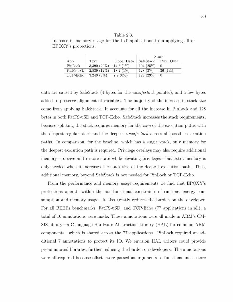
2.3 Increase in memory usage for the IoT applications from applying all ofEPOXY’s protections. . . . . . . . . . . . . . . . . . . . . . . . . . . . . . 39
2.4 Results of our verifier showing the number of privilege overlays (PO),average number of instructions in an overlay (Ave), maximum number ofinstructions in an overlay (Max), and the number of privilege overlays thatuse externally defined registers for addressing (Ext). . . . . . . . . . . . . . 41
2.5 Number of ROP gadgets for 1,000 variants the IoT applications. Lastindicates the largest number of variants for which one gadget survives. . . 43
2.6 Comparison of resource utilization and security properties of FreeRTOS-MPU(FreeRTOS) vs. EPOXY showing memory usage, total number ofinstructions executed (Exe), and the number of instructions that are priv-ileged (PI). . . . . . . . . . . . . . . . . . . . . . . . . . . . . . . . . . . . 45
3.1 Summary of ACES’ protection on PinLock for memory corruption vul-nerability in function HAL UART Receive IT. (X) – prevented, 7– notprevented . . . . . . . . . . . . . . . . . . . . . . . . . . . . . . . . . . . . 74
4.3 Comparison of QEMU vs. HALucinator using black box and reducedMMIO configurations. Showing number of basic blocks (BB) executed fordifferent emulation configurations, the number of functions intercepted,and the number of MMIO handled by the default handler. . . . . . . . . 120
4.4 Showing SLOC, number of functions (Func), and maximum and averagecyclomatic complexity (CC) of the handlers written for the STM32F4Cubeand ATMEL ASF libraries, and written for the associated peripheral models.122
2.1 The compilation work flow for an application using EPOXY. Our modifi-cations are shown in shaded regions. . . . . . . . . . . . . . . . . . . . . . 11
2.2 An example memory map showing the regions of memory commonly avail-able on an ARMv7-M architecture micro-controller. Note the cross hatchedareas have an address but no memory. . . . . . . . . . . . . . . . . . . . . 14
2.3 Diagram illustrating how the protection regions (R-x) defined in the MPUby EPOXY are applied to memory. Legend shows permissions and purposeof each region. Note regions R1-R3 (not shown) are developer defined. . . 16
2.4 Diagrams showing how diversification is applied. (a) Shows the RAMlayout with SafeStack applied before diversification techniques are applied.(b) Shows RAM the layout after diversification is applied. Note thatunused memory (gray) is dispersed throughout RAM, the order of variableswithin the data section (denoted 1-7) and bss section (greek letters) arerandomized. Regions A, B, C, and D are random sizes, and G is theunsafestack guard region. (c) Layout of functions before protection; (d)Layout of functions after trapping and randomizing function order. . . . . 26
2.5 Box plots showing percent increase in execution time (a) and energy (b)for the three IoT applications. The diamond shows the SafeStack onlybinary, and the star shows the privilege overlay only binary. . . . . . . . . 38
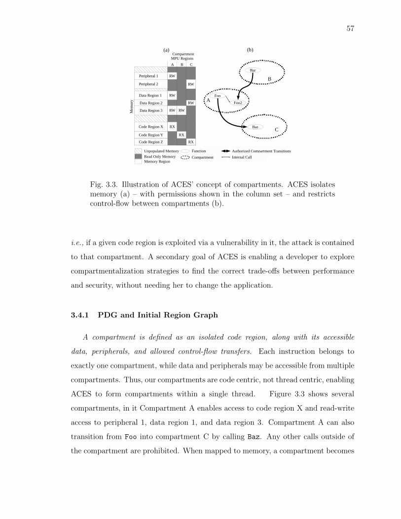
3.3 Illustration of ACES’ concept of compartments. ACES isolates memory(a) – with permissions shown in the column set – and restricts control-flowbetween compartments (b). . . . . . . . . . . . . . . . . . . . . . . . . . . 57
3.4 Compartment creation process and the resulting memory layout. (a) PDGis transformed to an initial region graph (b). A compartmentalizationpolicy is applied (c), followed by optimizations (d) and lowering to producethe final region graph (e). Which, is mapped to a compartmented memorylayout with associated MPU regions (f). . . . . . . . . . . . . . . . . . . . 58
3.6 Flash usage of ACES for test applications . . . . . . . . . . . . . . . . . . 83
3.7 RAM usage of ACES for test applications . . . . . . . . . . . . . . . . . . 85
4.1 Overview of HALucinator, with our contribution shown in gray. . . . . . . 96
4.2 (a) Software and hardware stack for an illustrative HTTP Server. (b)Conceptual illustration of HTTP Server when executing using HALucinator.98
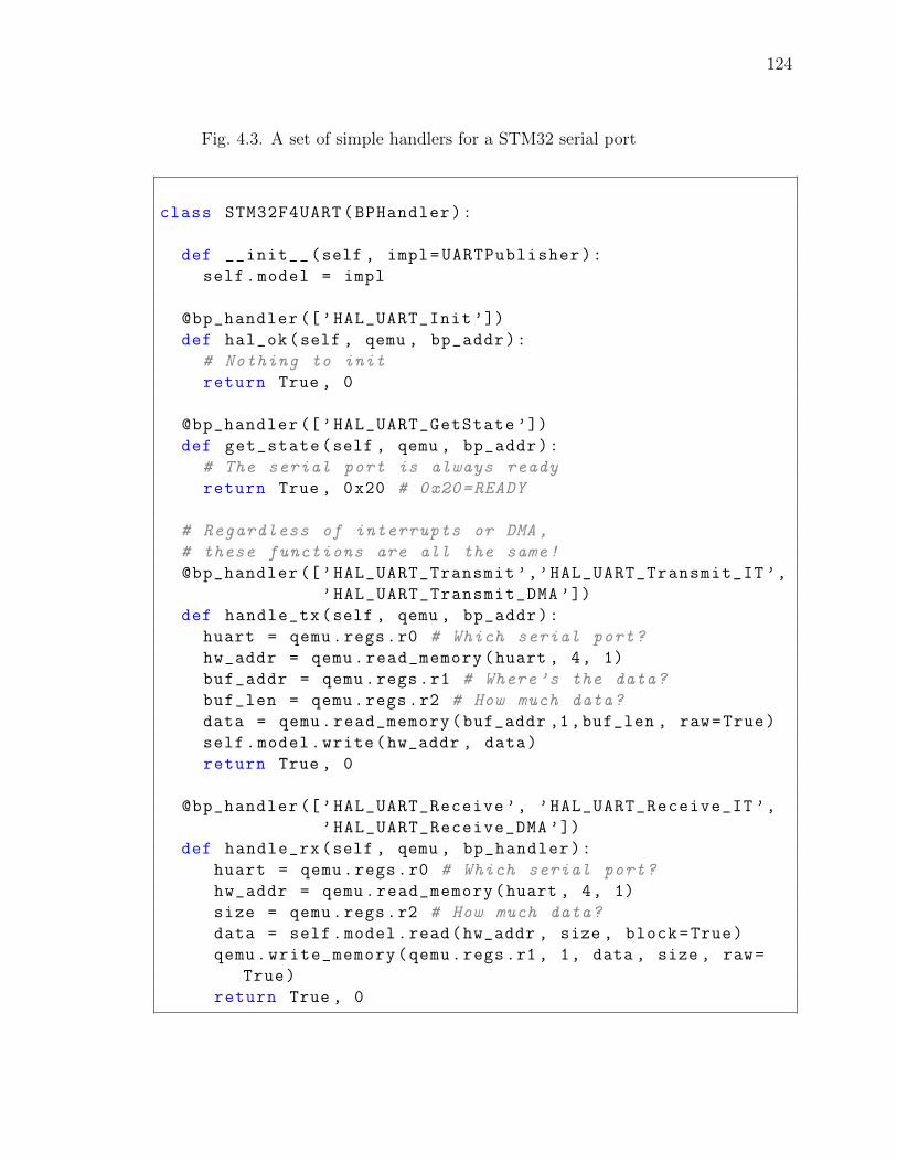
4.3 A set of simple handlers for a STM32 serial port . . . . . . . . . . . . . . 124
4.4 A more complex set of handlers that manage Atmel’s 6LoWPAN radiointerface . . . . . . . . . . . . . . . . . . . . . . . . . . . . . . . . . . . . 125
xiii
ABSTRACT
Clements, Abraham A. PhD, Purdue University, May 2019. Protecting Bare-metalSystems From Remote Exploitation. Major Professors: Saurabh Bagchi and MathiasPayer.
The Internet of Things is deploying large numbers of bare-metal systems that
have no protection against memory corruption and control-flow hijacking attacks.
These attacks have enabled unauthorized entry to hotel rooms, malicious control
of unmanned aerial vehicles, and invasions of privacy. Using static and dynamic
analysis these systems can utilize state-of-the-art testing techniques to identify and
prevent memory-corruption errors and employ defenses against memory corruption
and control-flow hijacking attacks in bare-metal systems that match or exceed those
currently employed on desktop systems. This is shown using three case studies.
(1) EPOXY which, automatically applies data execution prevention, diversity,
stack defenses, and separating privileged code from unprivileged code using a novel
technique called privileged overlaying. These protections prevent code injection at-
tacks, and reduce the number of privileged instruction to 0.06% verses an unprotected
application.
(2) Automatic Compartments for Embedded Systems (ACES), which automat-
ically creates compartments that enforce data integrity and code isolation within
bare-metal applications. ACES enables exploring policies to best meet security and
performance requirements for individual applications. Results show ACESs can form
10s of compartments within a single thread and has a 15% runtime overhead on
average.
(3) HALucinator breaks the requirement for specialized hardware to perform bare-
metal system testing. This enables state-of-the-art testing techniques –e.g., coverage
xiv
based fuzzing – to scale with the availability of commodity computers, leading to the
discovery of exploitable vulnerabilities in bare-metal systems.
Combined, these case studies advance the security of embedded system several
decades and provide essential protections for today’s connected devices.
1
1. INTRODUCTION
1.1 Motivation
The proliferation of the Internet of Things (IoT) is increasing the connectivity of
embedded systems. This connectivity and the scale of the IoT – over 9 billion devices
– exposes embedded systems to network-based attacks on an unprecedented scale. At-
tacks against IoT devices have already unleashed massive Denial of Service attacks [1],
invalidated traffic tickets [2], taken control of vehicles [3], and facilitated robbing ho-
tel rooms [4]. The importance of securing embedded systems extends beyond smart
things. Micro-controllers executing firmware are embedded in nearly everything –
e.g., in network cards [5], hard drive controllers [6], SD memory cards [7], WiFi con-
trollers, and Bluetooth interfaces. Vulnerabilities in these components can impact
only themselves but the system which they are connected to. For example, Google’s
Project Zero demonstrated how vulnerabilities in Broadcom’s WiFi controller could
be used to compromise the application processor in a cell phone [8].
This thesis focuses on protecting bare-metal embedded systems from remote mem-
ory corruption attacks. In bare-metal systems, the application runs without an oper-
ating system and is directly responsible for configuring hardware, accessing peripher-
als, and executing application logic. As such the software is privileged and has direct
access to the processor and peripherals. These bare-metal systems must satisfy strict
runtime guarantees on extremely constrained hardware platforms with few KBs of
memory, few MBs of Flash, and low CPU speed to minimize power and cost con-
straints. These constraints mean few if any protections are deployed on bare-metal
systems. As an exemplar, consider Broadcom’s WiFi controller did not even deploy
Data Execution Prevention (DEP) – a foundational defense in desktop systems for
over twenty years.
2
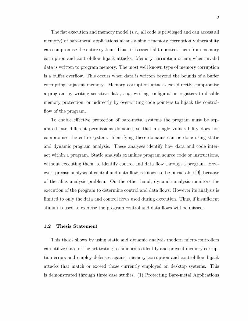
The flat execution and memory model (i.e., all code is privileged and can access all
memory) of bare-metal applications means a single memory corruption vulnerability
can compromise the entire system. Thus, it is essential to protect them from memory
corruption and control-flow hijack attacks. Memory corruption occurs when invalid
data is written to program memory. The most well known type of memory corruption
is a buffer overflow. This occurs when data is written beyond the bounds of a buffer
corrupting adjacent memory. Memory corruption attacks can directly compromise
a program by writing sensitive data, e.g., writing configuration registers to disable
memory protection, or indirectly by overwriting code pointers to hijack the control-
flow of the program.
To enable effective protection of bare-metal systems the program must be sep-
arated into different permissions domains, so that a single vulnerability does not
compromise the entire system. Identifying these domains can be done using static
and dynamic program analysis. These analyses identify how data and code inter-
act within a program. Static analysis examines program source code or instructions,
without executing them, to identify control and data flow through a program. How-
ever, precise analysis of control and data flow is known to be intractable [9], because
of the alias analysis problem. On the other hand, dynamic analysis monitors the
execution of the program to determine control and data flows. However its analysis is
limited to only the data and control flows used during execution. Thus, if insufficient
stimuli is used to exercise the program control and data flows will be missed.
1.2 Thesis Statement
This thesis shows by using static and dynamic analysis modern micro-controllers
can utilize state-of-the-art testing techniques to identify and prevent memory corrup-
tion errors and employ defenses against memory corruption and control-flow hijack
attacks that match or exceed those currently employed on desktop systems. This
is demonstrated through three case studies. (1) Protecting Bare-metal Applications
3
with Privilege Overlays (EPOXY), which uses a novel protection mechanism, called
privilege overlays, to identify only those instructions which require elevated privi-
leges and removes all other instructions from privileged execution. It then automati-
cally applies DEP, diversity, and stack protection. (2) Automatic Compartments for
Embedded Systems (ACES) which uses a developer specified policy to identify and
create compartments within a bare-metal system, and automatically enforces data in-
tegrity between compartments and restricts the instructions executable by any given
compartment. (3) HALucinator leverages hardware abstraction libraries and static
analysis of firmware to enable scalable creation of emulation platforms. This enables
dynamic analysis and state-of-the-art testing techniques, such as coverage guided
fuzzing on bare-metal firmware.
Each cases study is summarized in below and full details are provided in subse-
quent chapters.
1.3 Case Study 1: Protecting Bare-metal Applications with Privilege
Overlays (EPOXY)
EPOXY, described in Chapter 2, uses static analysis to automatically apply DEP,
diversity, stack defenses, and separates code into privileged and unprivileged execu-
tion. These protections prevent code injection attacks, reduces the number of priv-
ileged instruction to 0.06% of an unprotected application, and enable a single ROP
gadget to be used in at most 11% of binaries. On average it incurs only a 1.8%
increase in execution time, and 0.5% increase in energy.
Central to its design is a novel technique called privileged overlaying. This tech-
nique uses static analysis to identify all instructions and memory accesses that require
elevated privileges. It then instruments the program so that only those instructions
are executed with elevated privileges. This lays the foundation for effective use of
the hardware to enforce DEP. EPOXY also was the first to adapt the strong defenses
of SafeStack [10] to bare-metal systems. SafeStack uses static analysis to identify all
4
variables that cannot be proven to be used in a safe manner, and moves them to a
separate unsafe-stack. EPOXY automatically creates this stack, and needed guards
to isolate it from program data. Combined these protections show bare-metal sys-
tems can have protections as strong as those deployed on desktop systems with little
performance impact. By simpling recompiling the software, EPOXY fast forwards
bare-metal applications security several decades.
1.4 Case Study 2: Automatic Compartments for Embedded Systems
(ACES)
The second case study is described in detail in Chapter 3. It uses static and
dynamic analysis to enforce separation of privileges between different compartments
of a bare-metal system. Thus, applying the principle of least privileges—a bedrock
of security—to bare-metal systems. It breaks the single application into many small
compartments and enforces data integrity and control-flow integrity between com-
partments. It also restricts the code that is executable at any given time, reducing
the available code for use in code reuse attacks.
Creating the compartments is formulated as a graph reduction problem. This
formulation enables the investigation of many different types of policies, and the
automatic creation and enforcement of these compartments during execution. This
enables the developer to determine the correct balance of security and performance
for their application. Its evaluation shows that 10’s of compartments can be created
within a single bare-metal application with on average a 15% runtime overhead.
1.5 Case Study 3: HALucinator: Firmware Re-hosting Through Abstrac-
tion Layer Emulation
The final case study, HALucinator, shows how to execute firmware in an emulated
environment – i.e., re-host the firmware – to enable dynamic analysis of bare-metal
firmware and scalable testing. Re-hosting the firmware overcomes limitations imposed
5
by executing in hardware and removes the requirement for specialized hardware for
firmware testing. This enables testing that benefits from scaling in the number of
devices (e.g., fuzz testing), to be performed using commodity desktop/servers.]
The primary challenge to re-hosting firmware is the tight coupling of the firmware
to the hardware on which it executes. For example, firmware even before executing
the main function will often turn on and configure a clock source, and then poll
the clock to ensure it is ready before continuing. However, the emulator lacks this
clock source, and will either fault when trying to initialize the clock, or get stuck
in the polling loop. The coupling to hardware extends beyond clocks to include
all on-chip peripherals (e.g., network interfaces, timers, UARTs, GPIO, etc) in a
micro-controller and components on the system’s circuit board. Providing completely
accurate implementations for all possible components in a system is a daunting task,
which has made re-hosting firmware a manual and time consuming process, as a
custom emulator must be built for each firmware.
HALucinator, leverages the insight that the diversity of hardware also affects
firmware developers and to manage this problem they rely on abstraction libraries.
These libraries abstract the low-level hardware details, protocol stacks, and other com-
monly used functionalities into a set of application programming interfaces (APIs).
By identifying these abstraction libraries in a binary firmware and replacing them
with a high level model we can decouple the firmware from its hardware and enable
its re-hosting. This changes the supporting of diverse hardware in the emulator, to
the problem of supporting the different abstraction libraries. Which is a smaller prob-
lem as a single library supports many different chips. For example a micro-controller
manufacture will provide one library to abstract an entire family of devices.
Utilizing this technique we use HALucinator to enable dynamically emulating
firmware and demonstrate its use in performing dynamic analysis and fuzzing firmware.
Our fuzzing experiments identifies several vulnerabilities in the firmware showing
HALucinator’s utility in protecting bare-metal systems.
6
1.6 Work publication
This section covers work that has been published and is under review in support
of this thesis.
Published Works
• Protecting Bare-metal Applications with Privilege Overlays
Abraham A. Clements, Naif Almakhdhub, Khaled Saab, Prashast Srivastava,
Jinkyu Koo, Saurabh Bagchi, and Mathias Payer – Presented at 38th IEEE
Symposium on Security and Privacy, 2017
• Automatic Compartments for Embedded Systems (ACES)
Abraham A. Clements, Naif Almakhdhub, Saurabh Bagchi, and Mathias Payer
– Presented at 27th USENIX Security Symposium, 2018
Under Review
• HALucinator: Firmware Re-hosting Through Abstraction Layer Em-
ulation
Abraham A. Clements, Eric Gustafson, Tobias Scharnowski, Paul Grosen, David
Fritz, Christopher Kruegel, Giovanni Vigna, Saurabh Bagchi, Mathias Payer –
Under review at 28th USENIX Security Symposium, 2019
1.7 Summary
In summary, this thesis demonstrates how static and dynamic analysis can be used
to reduce the incidence of data corruption and control-flow hijacking on bare-metal
systems. The work contained herein shows bare-metal systems can deploy state-of-
the-art defenses within their constraints on memory, runtime, and energy. It also
enables dynamic analysis and large scale testing of bare-metal applications enabling
vulnerabilities be to prevented and identified. Combined these works fast-forward
bare-metal firmware security several decades, preparing them for the connected world
in which they now operate.
7
2. EPOXY: PROTECTING BARE-METAL EMBEDDED
SYSTEMS WITH PRIVILEGE OVERLAYS
This chapter shows how to automatically enforce Data Execution Prevention (DEP),
strong stack protections, and code reuse defenses on firmware used in bare-metal
systems, using a technique called privilege overlays. The chapter first lays out the
motivation and background for applying these defenses. The design and implemen-
tation of the used techniques are then given, and an evaluation of their impact on
run-time, memory usage, and energy then follows. This work was presented at the
IEEE Symposium on Security and Privacy Conference in 2017 [11].
2.1 Introduction
Embedded devices are ubiquitous. With more than 9 billion embedded processors
in use today, the number of devices has surpassed the number of humans. With the
rise of the “Internet of Things”, the number of embedded devices and their connectiv-
ity is exploding. These “things” include Amazon’s Dash button, utility smart meters,
smart locks, and smart TVs. Many of these devices are low cost with software run-
ning directly on the hardware, known as “bare-metal systems”. In such systems, the
application runs as privileged low-level software with direct access to the processor
and peripherals, without going through intervening operating system software layers.
These bare-metal systems satisfy strict runtime guarantees on extremely constrained
hardware platforms with few KBs of memory, few MBs of Flash, and low CPU speed
to minimize power and cost constraints.
With increasing network connectivity ensuring the security of these systems is
critical [12,13]. In 2016, hijacked smart devices like CCTV cameras and digital video
recorders launched the largest distributed denial of service (DDoS) attack to date [1].
8
The criticality of security for embedded systems extends beyond smart things. Micro-
controllers executing bare-metal software have been embedded so deeply into systems
that their existence is often overlooked, e.g., in network cards [5], hard drive con-
trollers [6], and SD memory cards [7]. We rely on these systems to provide secure
and reliable computation, communication, and data storage. Yet, they are built with
security paradigms that have been obsolete for several decades.
Embedded systems largely lack protection against code injection, control-flow hi-
jack, and data corruption attacks. Desktop systems, as surveyed in [14], employ many
defenses against these attacks such as: Data Execution Prevention (DEP), stack pro-
tections (e.g., stack canaries [15], separate return stacks [16], and SafeStack [10]),
tegrity (CPI) [10]. Consequently, attacks on desktop-class systems became harder
and often highly program dependent.
Achieving known security properties from desktop systems on embedded systems
poses fundamental design challenges. First, a single program is responsible for hard-
ware configuration, inputs, outputs, and application logic. Thus, the program must
be allowed to access all hardware resources and to execute all instructions (e.g., con-
figuring memory permissions). This causes a fundamental tension with best security
practices which require restricting access to some resources. Second, bare-metal sys-
tems have strict constraints on runtime, energy usage, and memory usage. This
requires all protections to be lightweight across these dimensions. Third, embedded
systems are purpose-built devices. As such, they have application-specific security
needs. For example, an IO register on one system may unlock a lock while on a
different system, it may control an LED used for debugging. Clearly the former is
a security-sensitive operation while the latter is not. Such application-specific re-
quirements should be supported in a manner that does not require the developer
to make intrusive changes within her application code. Combined, these challenges
have meant that security protection for code injection, control-flow hijack, and data
corruption attacks are simply left out from bare-metal systems.
9
As an illustrative example, consider the application of DEP to bare-metal sys-
tems. DEP, which enforces W ⊕ X on all memory regions, is applied on desktops
using a Memory Management Unit (MMU), which is not present on micro-controllers.
However, many modern micro-controllers have a peripheral called the Memory Pro-
tection Unit (MPU) that can enforce read, write, and execute permissions on regions
of the physical memory. At first glance, it may appear that DEP can be achieved in
a straightforward manner through the use of the MPU. Unfortunately, we find that
this is not the case: the MPU protection can be easily disabled, because there is
no isolation of privileges. Thus, a vulnerability anywhere in the program can write
the MPU’s control register to disable it. A testimony to the challenges of correctly
using an MPU are the struggles existing embedded OSs have in using it for security
protection, even for well-known protections such as DEP. FreeRTOS [21], a popu-
lar operating system for low-end micro-controllers, leaves its stacks and RAM to be
writable and executable. By FreeRTOS’s own admission, the MPU port is seldom
used and is not well maintained [22]. This was evidenced by multiple releases in 2016
where MPU support did not even compile [23,24].
To address all of these challenges, we developed EPOXY (Embedded Privilege
Overlay on X hardware with Y software), a compiler that brings both generic and
system-specific protections to bare-metal applications. This compiler adds additional
passes to a traditional LLVM cross-compilation flow, as shown in Figure 2.1. These
passes add protection against code injection, control-flow hijack and data corruption
attacks, and direct manipulation of IO. Central to our design is a lightweight privilege
overlay, which solves the dichotomy of allowing the program developer to assume
access to all instructions and memory but restrict access at runtime. To do this,
EPOXY reduces execution privileges of the entire application. Then, using static
analysis, only instructions requiring elevated privileges are added to the privilege
overlay to enable privileges just prior to their execution. EPOXY draws its inputs
from a security configuration file, thus decoupling the implementation of security
decisions from application design and achieves all the security protections without
10
any application code modification. Combined, these protections provide application-
specific security for bare-metal systems that are essential on modern computers.
In adapting fine-grained diversification techniques [18], EPOXY leverages unique
aspects of bare-metal systems, specifically all memory is dedicated to a single appli-
cation and the maximum memory requirements are determined a priori. This enables
the amount of unused memory to be calculated and used to increase diversification
entropy. EPOXY then adapts the protection of SafeStack [10], enabling strong stack
protection within the constraints of bare-metal systems.
Our prototype implemenation of EPOXY supports the ARMv7-M architecture,
which includes the popular Cortex-M3, Cortex-M4, and Cortex-M7 micro-controllers.
Our techniques are general and should be applicable to any micro-controller that
supports at least two modes of execution (privileged and unprivileged) and has an
MPU. We evaluate EPOXY on 75 benchmark applications and three representative
IoT applications that each stress different sub-systems. Our performance results
for execution time, power usage, and memory usage show that our techniques work
within the constraints of bare-metal applications. Overheads for the benchmarks
average 1.6% for runtime and 1.1% for energy. For the IoT applications, the average
overhead is 1.8% for runtime, and 0.5% for energy. We evaluate the effectiveness of our
diversification techniques, using a Return Oriented Programming (ROP) compiler [25]
that finds ROP-based exploits. For our three IoT applications, using 1,000 different
binaries of each, no gadget survives across more than 107 binaries. This implies that
an adversary cannot reverse engineer a single binary and create a ROP chain with a
single gadget that scales beyond a small fraction of devices.
In summary, this work: (1) identifies the essential components needed to apply
proven security techniques to bare-metal systems; (2) implements them as a transpar-
ent runtime privilege overlay, without modifying existing source code; (3) provides
state-of-the-art protections (stack protections and diversification of code and data
regions) for bare-metal systems within the strict requirements of run-time, memory
size, and power usage; (4) demonstrates that these techniques are effective from a
11
GNU Linker
Bin
HAL Src
Linker Script
LLVM Linker
Plugin
App Src
Passes
SafeStack
Backend
Diversification
LLVM Linker
Plugin
Stdlib Src
`
Options
LLVM
Bitcode
GCCClang
Privilege
Overlaying
Stdlib
Fig. 2.1. The compilation work flow for an application using EPOXY.Our modifications are shown in shaded regions.
security standpoint on bare-metal systems. Simply put, EPOXY brings bare-metal
application security forward several decades and applies protections essential for to-
day’s connected systems.
2.2 Threat Model and Platform Assumptions
We assume a remote attacker with knowledge of a generic memory corruption
vulnerability, i.e., the application running on the embedded system itself is buggy
but not malicious. The goal of the attacker is to either achieve code execution (e.g.,
injecting her own code, reusing existing code through ROP or performing Data-
oriented Programming [26]), corrupt specific data, or directly manipulate security-
critical outputs of a system by sending data to specific IO pins. We assume the
attacker exploits a write-what-where vulnerability, i.e., one which allows the attacker
to write any data to any memory location that she wants. The attacker may have
obtained the vulnerability through a variety of means, e.g., source code analysis, or
12
reverse engineering the binary that runs on a different device and identifying security
flaws in it.
We also assume that the attacker does not have access to the specific instance of
the (diversified) firmware running on the target device. Our applied defenses provide
foundational protections, which are complementary to and assumed by, many modern
defenses such as, the memory disclosure prevention work by Braden et. al. [27]. We
do not protect against attacks that replace the existing firmware with a compromised
firmware. Orthogonal techniques such as code signing should be used to prevent this
type of attack.
We make the following assumptions about the target system. First, it is running a
single bare-metal application, which utilizes a single stack and has no restrictions on
the memory addresses, peripherals, or registers that it can access or instructions that
it can execute. This is the standard mode of execution of applications on bare-metal
systems, e.g., is the case with every single benchmark application and IoT application
that we use in the evaluation and that we surveyed from the vendors of the ARM-
equipped boards. Second, we require the micro-controller to support at least two
execution privilege levels, and have a means to enforce access controls on memory for
these privilege levels. These access controls include marking regions of memory as
read, write, and/or execute. Typically, an MPU provides this capability on a micro-
controller. We looked at over 100 Cortex-M3, M4, and M7 series micro-controllers
from ARM and an MPU was present on all but one. Micro-controllers from other
vendors, such as AVR32 from Atmel, also have an MPU.
2.3 Architecture Background Information
This section presents architecture information that is needed to understand the
attack vectors and the defense mechanisms in EPOXY. Bare-metal systems have low
level access to hardware; this enables an attacker, with a write-what-where vulnerabil-
ity, to manipulate the system in ways that are unavailable to applications on desktop
13
systems. Defense strategies must consider these attack avenues, and the constraints
of hardware available to mitigate threats. For specificity, we focus on the ARMv7-M
architecture which is implemented in ARM Cortex-M(3,4,7) micro-controllers. The
general techniques are applicable to other architectures subject to the assumptions
laid out in Section 2.2. We present key details of the ARMv7-M architecture, full
details are in the ARMv7-M Architecture Reference Manual [28].
2.3.1 Memory Map
In our threat model, the attacker has a write-what-where vulnerability that can
be used to write to any memory address; therefore, it is essential to understand the
memory layout of the system. Note that these systems use a single, unified mem-
ory space. A representative memory map illustrating the different memory regions
is shown in Figure 2.2. At the very bottom of memory is a region of aliased mem-
ory. When an access is made to the aliased region, the access is fulfilled by accessing
physical memory that is aliased, which could be in the Internal RAM, Internal Flash,
or External Memory. The alias itself is specified through a hardware configuration
register. Thus, memory mapped by the aliased region is addressable using two ad-
dresses: its default address (e.g., the address of Internal RAM, Internal Flash, or
External Memory) and address of the aliased region. This implies that a defender
has to configure identical permissions for the aliased memory region and the actual
memory region that it points to. A common peripheral (usually a memory controller)
contains a memory-mapped register that sets the physical memory addressed by the
aliased region. A defender must protect both the register that controls which memory
is aliased, in addition to the physical and aliased memory locations.
Moving up the address space we come to Internal Flash, this is Flash memory
that is located inside the micro-controller. On ARMv7-M devices it ranges in size
from a couple KB to a couple MB. The program code and read only data are usually
stored here. If no permissions are enforced, an attacker may directly manipulate
14
Fig. 2.2. An example memory map showing the regions of memory com-monly available on an ARMv7-M architecture micro-controller. Note thecross hatched areas have an address but no memory.
code1. Address space layout randomization is not applied in practice and the same
binary is loaded on all devices, which enables code reuse attacks like ROP. Above
the Flash is RAM which holds the heap, stack, and global data (initialized data and
uninitialized bss sections). Common sizes range from 1KB to a couple hundred KB
and it is usually smaller than the Flash. By default this area is read, write, and
execute-enabled, making it vulnerable to code injection attacks. Additionally, the
stack employs no protection and thus is vulnerable to stack smashing attacks which
can overwrite return addresses and hijack the control flow of the application.
Located above the RAM are the peripherals. This area is sparsely populated
and consists of fixed addresses which control hardware peripherals. Peripherals in-
clude: General Purpose Input and Output (GPIO), serial communication (UARTS),
Ethernet controllers, cryptography accelerators, and many others. Each peripheral
is configured, and used by reading and writing to specific memory addresses called
memory-mapped registers. For example, a smart lock application will use an output
pin of the micro-controller to actuate its locking mechanism. In software this will
1In Flash a 1 may be changed to a 0 without erasing an entire block, parity checks are also commonto detect single bit flips. This restricts the changes that can directly be made to code; however, awily attacker may still be able to manipulate the code in a malicious way.
15
show up as a write to a fixed address. An adversary can directly open the lock by
writing to the GPIO register using a write-what-where vulnerability, bypassing any
authentication mechanism in the application.
The second region from the top is reserved for external memory and co-processors.
This may include things like external RAM or Flash. However, on many small em-
bedded systems nothing is present in this area. If used, it is sparsely populated and
the opportunities presented to an attacker are system and program specific. The final
area is the System Control Block (SCB). This is a set of memory-mapped registers
defined by ARM and present in every ARMv7-M micro-controller. It controls the
MPU configuration, interrupt vector location, system reset, and interrupt priorities.
Since the SCB contains the MPU configuration registers, an attacker can disable the
MPU simply by writing a 0 to the lowest bit of the MPU CTRL register located at
address 0xE000ED94. Similarly, the location of the interrupt vector table is set by
writing the VTOR register at 0xE000ED08. These indicate that the SCB region is
critical from a security standpoint.
2.3.2 Execution Privileges Modes
Like their x86 counterparts, ARMv7-M processors can execute in different priv-
ilege modes. However, they only support two modes: privileged and unprivileged.
In the current default mode of operation, the entire application executes in privi-
leged mode, which means that all privileged instructions and all memory accesses are
allowed. Thus, we cannot indiscriminately reduce the privilege level of the applica-
tion, for fear of breaking the application’s functionality. Once privileges are reduced
the only way to elevate privileges is through an exception. All exceptions execute
in privileged mode and software can invoke an exception by executing an SVC (for
“supervisor call”) instruction. This same mechanism is used to create a system call
in a traditional OS.
16
Fig. 2.3. Diagram illustrating how the protection regions (R-x) defined inthe MPU by EPOXY are applied to memory. Legend shows permissionsand purpose of each region. Note regions R1-R3 (not shown) are developerdefined.
2.3.3 Memory Protection Unit
ARMv7-M devices have a Memory Protection Unit or MPU which can be used to
set read, write, or execute permissions on regions of the physical memory. The MPU
is similar to an MMU, but it does not provide virtual memory addressing. In effect,
the MPU adds an access control layer over the physical memory but memory is still
addressed by its physical addresses. The MPU defines read, write, and execute priv-
ileges for both privileged and unprivileged modes. It also enables making regions of
memory non executable (“execute never” in ARM’s terminology). It supports setting
up to 8 regions, numbered from 0 to 7, with the following restrictions: (1) A region’s
size can be from 32 Bytes to 4 GBytes, in powers of two; (2) Each region must be
size-aligned (e.g., if the region is 16KB, it must start on a multiple of 16KB); (3) If
there is a conflict of permissions (through overlapping regions), then the higher num-
bered region’s permissions take effect. Figure 2.3 illustrates how memory permissions
are applied.
For the remainder of this paper we will use the following notations to describe
permissions for a memory region: (P-R?W ?,U-R?W ?,X| −?) which encodes read and
write permissions for privileged mode (P), unprivileged mode (U), and execution
permission for both privileged and unprivileged mode. For example, the tuple (P-
17
RW,U-R,X) encodes a region as executable, read-write for privileged mode and exe-
cutable, read-only access for unprivileged mode. Note, execute permissions are set for
both privileged and unprivileged mode. For code to be executed, read access must
be granted. Thus, unprivileged code can be prevented from executing a region by
disabling read access to it.
2.3.4 Background Summary
Current bare-metal system design exposes a large attack surface—memory cor-
ruption, code injection, control-flow hijack attacks, writing to security-critical but
system-specific IO, and modification of registers crucial for system operation such as
the SCB and MPU configuration. Execution privilege modes and the MPU provide
the hardware foundation that can be used to develop techniques that will reduce this
vast attack surface. However, the development assumption that all instructions and
all memory locations are accessible is in direct conflict with the security requirements,
as some instructions and memory accesses can exploit the attack surface and need
to be restricted. Next we present the design of our solution EPOXY, which resolves
this tension by using privilege overlays, along with various diversification techniques
to reduce the attack surface.
2.4 Design
EPOXY’s goal is to apply system specific protections to bare-metal applications.
This requires meeting several requirements: (1) Protections must be flexible as pro-
tected areas vary from system to system; (2) The compiler must enable the enforce-
ment of policies that protect against malicious code injection, code reuse attacks,
global data corruption, and direct manipulation of IO; (3) Enforcement of the poli-
cies must satisfy the non-functional constraints—runtime, energy usage, and memory
usage should not be significantly higher than in the baseline insecure execution. (4)
18
The protections should not cause the application developers to make changes to their
development workflow and ideally would involve no application code changes.
EPOXY’s design utilizes four components to apply protections to bare-metal sys-
tems, while achieving the above four goals. They are: (1) access controls which limit
the use of specific instructions and accesses to sensitive memory locations, (2) our
novel privilege overlay which imposes the access control on the unmodified applica-
tion, (3) an adapted SafeStack, and (4) diversification techniques which utilize all
available memory.
2.4.1 Access Controls
Access controls are used to protect against code injection attacks and defend
against direct manipulation of IO. Access controls specify the read, write, and exe-
cute permissions for each memory region and the instructions which can be executed
for a given execution mode. As described in Section 2.3, modern micro-controllers
contain an MPU and multiple execution modes. These are designed to enable DEP
and to restrict access to specific memory locations. We utilize the MPU and mul-
tiple execution modes to enforce access controls in our design. Using this available
hardware, rather than using a software only approach, helps minimize the impact on
runtime, energy consumption, and memory usage. On our target architecture, IO is
handled through memory-mapped registers as well and thus, the MPU can be used
to restrict access to sensitive IO. The counter argument to the use of the MPU is
that it imposes restrictions—how many memory regions can be configured (8 in our
chosen ARM architecture) and how large each region needs to be and how it should be
aligned (Section 2.3.3). However, we still choose to use the MPU and this explains in
part the low overhead that EPOXY incurs (Table 2.2). While the MPU and the pro-
cessor execution modes can enforce access controls at runtime they must be properly
configured to enable robust protection. We first identify the proper access controls
and how to enforce them. We then use the compiler to generate the needed hardware
19
configuration to enforce access controls at runtime. Attempts to access disallowed
locations trap to a fault handler. The action the fault handler takes is application
specific, e.g., halting the system, which provides the strongest protects as it prevents
repeated attack attempts.
The required access controls and mechanisms to enforce them can be divided into
two parts: architecture dependent and system specific. Architecture-dependent access
controls: All systems using a specific architecture (e.g., ARMv7-M) have a shared set
of required access controls. They must restrict access to instructions and memory-
mapped registers that can undermine the security of the system. The instructions
that require execution in privileged mode are specified in the processor architecture
and are typically those that change special-purpose registers, such as the program
status register (the MSR and CPS instructions). Access to these instructions is limited
by executing the application by default in unprivileged mode. Memory-mapped reg-
isters, such as the MPU configuration registers, and interrupt vector offset register,
are common to an architecture and must be protected. In our design, this is done
by configuring the MPU to only allow access to these regions (registers) from the
privileged mode.
System-specific access controls: These are composed of setting W ⊕ X on code
and data, protection of the alias control register, and protecting any sensitive IO.
W ⊕X should be applied to every system; however, the locations of code and data
change from system to system, making the required configuration to enforce it system
specific. For example, each micro-controller has different amounts of memory and a
developer may place code and data in different regions, depending on her require-
ments. The peripheral that controls the aliased memory is also system specific and
needs protection and thus, access to it should be set for the privileged mode only.
Last, what IO is sensitive varies from system to system and only the subset of IO
that is sensitive need be restricted to the privileged mode.
To simplify the implementation of the correct access controls, our compiler gen-
erates the necessary system configuration automatically. At the linking stage, our
20
compiler extracts information (location, size, and permissions) for the code region
and the data region. In addition, the developer provides on a per-application basis
information about the location and size of the alias control register and what IO
is sensitive. The compiler then uses this information, along with the architecture-
specific access controls, to generate the MPU configuration. The MPU configuration
requires writing the correct bits to specific registers to enforce the access controls.
Our compiler pass adds code to system startup to configure the MPU ( Figure 2.3
and Table 2.1). The startup code thus drops the privileges of the application that is
about to execute, causing it to start execution in unprivileged mode.
2.4.2 Privilege Overlay
We maintain the developer’s assumption of access to all instructions and mem-
ory locations by using a technique that we call, privilege overlay. This technique,
identifies all instructions and memory accesses which are restricted by the access
controls—referred to as restricted operations—and elevates just these instructions.
Conceptually, this is like overlaying the original program with a mask which elevates
just those instructions which require privileged mode. In some ways, this privilege
overlaying is similar to an application making an operating system call and transi-
tioning from unprivileged mode to privileged mode. However, here, instead of being
a fixed set of calls which operate in the operating system’s context, it creates a min-
imal set of instructions (loads and stores from and to sensitive locations and two
specific instructions) that execute in their original context (the only context used
in a bare-metal application execution) after being given permissions to perform the
restricted operation. By elevating just those instructions which perform restricted
operations through the privilege overlay, we simplify the development process and by
carefully selecting the restricted operations, we limit the power of a write-what-where
vulnerability.
21
Privilege overlaying requires two mechanisms: A mechanism to elevate privileges
for just the restricted operations and a mechanism to identify all the restricted oper-
ations. Architectures employing multiple execution modes provide a mechanism for
requesting the execution of higher level software. On ARM, this is the SVC instruc-
tion which causes an exception handler to be invoked. This handler checks if the call
came from an authorized location, and if so, it elevates the execution mode to the
privileged mode and returns to the original context. If it was not from an authorized
location, then it passes the request on to the original handler without elevating the
privilege, i.e., it denies the request silently. The compiler identifies each restricted
operation and prepends it with a call to the SVC handler and, immediately after
the restricted operation, adds instructions that drop the execution privileges. Thus,
each restricted operation executes in privileged mode and then immediately returns
to unprivileged mode.
The restrictions in the way MPU configuration can be specified, creates challenges
for EPOXY. The MPU is restricted to protecting blocks of memory of size at least
32 Bytes, and sometimes these blocks include both memory-mapped registers that
must be protected to ensure system integrity, and those which need to be accessed for
correct functionality. For example, the Vector Table Offset Register (VTOR) and the
Application Interrupt and Reset Control Register (AIRCR) are immediately adjacent
to each other in one 32 Byte region. The VTOR is used to point to the location of the
interrupt vector table and is thus a security critical register, while the AIRCR is used
(among other things) for the software running on the device to request a system reset
(say, to reload a new firmware image) and is thus not security critical. There is no
way to set permissions on the VTOR without also applying the same permissions to
the AIRCR. EPOXY overcomes this restriction by adding accesses to the AIRCR to
the privilege overlay, thus elevating accesses whenever the AIRCR is being accessed.
22
2.4.3 Identifying Restricted Operations
To identify restricted operations we utilize static analysis and optionally, source
code annotations by the developer. Using static analysis enables the compiler to
identify many of the restricted operations, reducing the burden on the developer. We
use two analyses to identify restricted operations; one for restricted instructions and a
second to identify restricted memory accesses. Restricted instructions are defined by
the Instruction Set Architecture (ISA) and require execution in privileged mode. For
the ARMv7-M architecture these are the CPS and MSR instructions, each of which
controls specific flags in the program status register, such as enabling or disabling
interrupt processing. These privileged instructions are identified by string matching
during the appropriate LLVM pass. Identifying restricted memory accesses however
is more challenging.
An important observation enables EPOXY to identify most restricted accesses.
In our case, the memory addresses being accessed are memory-mapped registers.
In software, these accesses are reads and writes to fixed addresses. Typically, a
Hardware Abstraction Layer (HAL) is used to make these accesses. Our study of
HAL’s identified three patterns that cover most accesses to these registers. The first
pattern uses a macro to directly access a hard-coded address. The second pattern
uses a similar macro and a structure to access fixed offsets from a hard-coded address.
The last pattern uses a structure pointer set to a hard-coded address. All use a hard-
coded address or fixed offsets from them. The use of hard-coded addresses, and fixed
offsets from them, are readily identifiable by static analysis.
Our static analysis uses backward slicing to identify these accesses. A backward
slice contains all instructions that affect the operands of a particular instruction. This
enables identifying the potential values of operands at a particular location in a pro-
gram. We limit our slices to a single function and examine only the definitions for
the address operand of load and store operations. Accesses to sensitive registers are
identified by checking if the address being accessed is derived from a constant address.
23
This static analysis captures many of the restricted memory accesses; however, not all
accesses can be statically identified and manual annotations (likely by the developer)
are required in these cases. Note that we observed few annotations in practice and
most are generic per hardware platform, i.e., they can be provided by the manufac-
turer. This primarily occurs when memory-mapped registers are used as arguments
in function calls or when aliasing of memory-mapped registers occurs. Aliasing oc-
curs when the register is not directly referenced, but is assigned to a pointer, and
multiple copies of that pointer are made so that the register is now accessible via
many different pointers. These point to two limitations of our current static analysis.
Our backward slicing is limited to a single function and with some bounded engineer-
ing effort, we can expand it to perform inter-procedural analysis. To overcome the
second limitation though requires precise alias analysis, which is undecidable in the
general case [9]. However, embedded programs—and specifically access to memory
mapped registers—are constrained in their program structures reducing the concern
of aliasing in this domain.
2.4.4 Modified SafeStack
EPOXY defends against control-flow hijacking attack by employing SafeStack [10],
modified to bare-metal systems. SafeStack is a protection mechanism that uses static
analysis to move local variables which may be used in an unsafe manner to a separate
unsafestack. A variable is unsafe if it may access memory out-of-bounds or if it
escapes the current function. For example, if a supplied parameter is used as the
index of an array access, the array will be placed on the unsafestack. It utilizes virtual
addressing to isolate the unsafestack from the rest of the memory. By design, return
addresses are always placed on the regular stack because they have to be protected
from illegal accesses. SafeStack ensures that illegal accesses may only happen on
items on the unsafestack. In addition to its security properties, Safestack has low
runtime overhead (generally below 1% [10] §5.2) and a deterministic impact on stack
24
sizes makes it a good fit for bare-metal systems. The deterministic impact means—
assuming known maximum bounds for recursion—the maximum size for both the
regular and unsafestack is fixed and can be determined a priori. Use of recursion
without knowing its bounds is bad design for bare-metal systems.
While the low runtime overhead of SafeStack makes it suitable for bare-metal
systems, it needs an isolated memory region to be effective. The original technique,
deployed on Intel architectures, relied on hardware support for isolation (either seg-
mentation or virtual memory) to ensure low overhead. For example, it made the safe
region accessible through a dedicated segment register, which is otherwise unused,
and configured limits for all other segment registers to make the region inaccessible
through them (on x86). Such hardware segment registers and hardware protection
are not available in embedded architectures. The alternate pure software mechanism
based on Software Fault Isolation [29] would be too expensive for our embedded ap-
plications because it requires that all memory operations in a program are masked.
While on some architectures with a large amount of (virtual) memory, this instru-
mentation can be lightweight (e.g., a single and operation if the safe region occupies a
linear part of the address space – encoded in a mask, resulting in about 5% overhead),
here masking is unlikely to work because the safe region will occupy a smaller and
unaligned part of the scarce RAM memory.
Therefore, to apply the SafeStack principle to bare-metal systems, we place the
unsafestack at the top of the RAM, and make the stack grow up, as shown in Fig-
ure 2.4a. We then place a guard between the unsafestack and the other regions in
RAM, shown as the black region in the figure. This follows best practices for em-
bedded systems to always grow a stack away from other memory regions. The guard
is created as part of the MPU configurations generated by the compiler. The guard
region is inaccessible to both privileged and unprivileged code (i.e., privileges are
(P-,W-,XN)). Any overflow on the unsafestack will cause a fault either by accessing
beyond the bounds of memory, or trying to access the guard region. It also prevents
traditional stack smashing attacks because any local variable that can be overflown
25
will be placed on the unsafestack while return addresses are placed on the regular
stack. Our design for the first time provides strong stack protection on bare-metal
embedded systems.
2.5 Implementation
2.5.1 Access Controls
We developed a prototype implementation of EPOXY, building on LLVM 3.9 [30].
In our implementation, access controls are specified using a template. The template
consists of a set of regions that map to MPU region configurations (see Section 2.3.3
for the configuration details). Due to current hardware restrictions, a maximum of
8 regions are supported. Our basis template uses five regions as shown in Table 2.1.
Region 0 encodes default permissions. Using region 0 ensures all other regions over-
ride these permissions. We then use the highest regions and work down to assign
permissions to ensure that the appropriate permissions are enforced. Region 7 is used
to enforce W ⊕ X on executable memory. This region covers both the executable
memory and its aliased addresses starting at address 0. The three remaining regions
(4-6) can be defined in any order and protect the SCB, alias control register, and the
unsafestack guard.
The template can be modified to accommodate system specific requirements, e.g.,
changing the start address and size of a particular region. For example, the two micro-
controllers used for evaluation place the alias control register at different physical
addresses. Thus, we modified the start address and size for each micro-controller.
Regions 1-3 are unused and can be used to protect sensitive IO that is application
specific. To do this, the start address and size cover the peripheral and permissions
are set to (P-RW,U-RW,XN). The addresses for all peripherals are given in micro-
controller documentation provided by the vendor. The use of the template enables
system specific access controls to be placed on the system. It also decouples the
development of access control mechanisms and application logic.
26
Fig
.2.
4.D
iagr
ams
show
ing
how
div
ersi
fica
tion
isap
plied
.(a
)Show
sth
eR
AM
layo
ut
wit
hSaf
eSta
ckap
plied
bef
ore
div
ersi
fica
tion
tech
niq
ues
are
applied
.(b
)Show
sR
AM
the
layo
ut
afte
rdiv
ersi
fica
tion
isap
plied
.N
ote
that
unuse
dm
emor
y(g
ray)
isdis
per
sed
thro
ugh
out
RA
M,th
eor
der
ofva
riab
les
wit
hin
the
dat
ase
ctio
n(d
enot
ed1-
7)an
dbss
sect
ion
(gre
ekle
tter
s)ar
era
ndom
ized
.R
egio
ns
A,
B,
C,
and
Dar
era
ndom
size
s,an
dG
isth
eu
nsa
fest
ack
guar
dre
gion
.(c
)L
ayou
tof
funct
ions
bef
ore
pro
tect
ion;
(d)
Lay
out
offu
nct
ions
afte
rtr
appin
gan
dra
ndom
izin
gfu
nct
ion
order
.
27
Table 2.1.The MPU configuration used for EPOXY. For overlapping regions thehighest numbered region (R) takes effect.
We implemented a pass in LLVM that generates code to configure the MPU based
on the template. The code writes the appropriate values to the MPU configuration
registers to enforce the access controls given in the template, and then reduces exe-
cution privileges. The code is called at the very beginning of main. Thus all of main
and the rest of the program executes with reduced privileges.
2.5.2 Privilege Overlays
Privileged overlay mechanisms (i.e., privilege elevation and restricted operation
identification) are implemented using an LLVM pass. To elevate privileges two com-
ponents are used. They are a privilege requester and a request handler. Requests are
made to the handler by adding code which performs the operations around restricted
operations, as shown in Algorithm 1. This code saves the execution state and executes
a SVC (SVC FE) to elevate privileges. The selected instructions are then executed
in privileged mode, followed by a code sequence that drops privileges by setting the
zero bit in the control register. Note that this sequence of instructions can safely be
executed as part of an interrupt handler routine as interrupts execute with privileges
and, in that mode, the CPU ignores both the SVC instruction and the write to the
control register.
The request handler intercepts three interrupt service routines and implements
the logic shown in Algorithm 2. The handler stores register state (R0-R3 and LR
– the remaining registers are not used) and checks that the caller is an SVC FE
instruction. Authenticating the call site ensures that only requests from legitimate
locations are allowed. Due to W ⊕X, no illegal SVC FE instruction can be injected.
If the interrupt was caused by something other than the SVC FE instruction the
original interrupt handler is called.
The request handler is injected by the compiler by intercepting three interrupt
handlers. These are: the SVC handler, the Hard Fault handler, and the Non Maskable
Interrupt handler. Note that executing an SVC instruction causes an interrupt. When
29
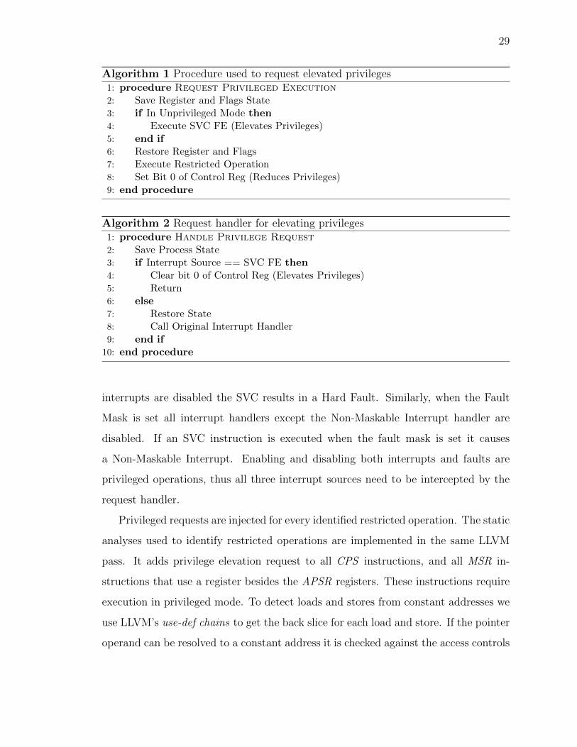
Algorithm 1 Procedure used to request elevated privileges1: procedure Request Privileged Execution2: Save Register and Flags State3: if In Unprivileged Mode then4: Execute SVC FE (Elevates Privileges)5: end if6: Restore Register and Flags7: Execute Restricted Operation8: Set Bit 0 of Control Reg (Reduces Privileges)9: end procedure
Algorithm 2 Request handler for elevating privileges1: procedure Handle Privilege Request2: Save Process State3: if Interrupt Source == SVC FE then4: Clear bit 0 of Control Reg (Elevates Privileges)5: Return6: else7: Restore State8: Call Original Interrupt Handler9: end if
10: end procedure
interrupts are disabled the SVC results in a Hard Fault. Similarly, when the Fault
Mask is set all interrupt handlers except the Non-Maskable Interrupt handler are
disabled. If an SVC instruction is executed when the fault mask is set it causes
a Non-Maskable Interrupt. Enabling and disabling both interrupts and faults are
privileged operations, thus all three interrupt sources need to be intercepted by the
request handler.
Privileged requests are injected for every identified restricted operation. The static
analyses used to identify restricted operations are implemented in the same LLVM
pass. It adds privilege elevation request to all CPS instructions, and all MSR in-
structions that use a register besides the APSR registers. These instructions require
execution in privileged mode. To detect loads and stores from constant addresses we
use LLVM’s use-def chains to get the back slice for each load and store. If the pointer
operand can be resolved to a constant address it is checked against the access controls
30
applied in the MPU. If the MPU’s configuration restricts that access a privilege ele-
vation request is added around the operation. This identifies many of the restricted
operations. Annotations can be used to identify additional restricted operations.
2.5.3 SafeStack and Diversification
The SafeStack in EPOXY extends and modifies the SafeStack implemented in
LLVM 3.9. Our changes enable support for the ARMv7-M architecture, change the
stack to grow up, and use a global variable to store the unsafestack pointer. Stack
offsets are applied with global data randomization. Global data randomization is
applied using a compiler pass. It takes the amount of unused RAM as a parameter
which is then randomly split into five groups. These groups specify how much memory
can be used in each of the following regions: stack offset, data region, bss region,
unsafestack offset, and unused. The number of bytes added to each section is a
multiple of four to preserve alignment of variables on word boundaries. The data
and bss region diversity is increased by adding dummy variables to each region. Note
that adding dummy variables to the data regions increases the Flash used because
the initial values for the data section are stored as an array in the Flash and copied
to RAM at reset. However, Flash capacity on a micro-controller is usually several
times larger than the RAM capacity and thus, this is less of a concern. Further an
option can be used to restrict the amount of memory for dummy variables in the data
section. Dummy variables in the bss do not increase the amount of Flash used.
Another LLVM pass is used to randomize the function order. This pass takes
the amount of memory that can be dispersed throughout the text section. It then
disperses this memory between the function by adding trap functions to the global
function list. The global function list is then randomized, and the linker lays out
the functions in the shuffled order in the final binary. A trap function is a small
function which, if executed, jumps to a fault handler. These traps are never executed
31
in a benign execution and thus incur no runtime overhead but detect unexpected
execution.
2.6 Evaluation
We evaluate the performance of EPOXY with respect to the design goals, both
in terms of security and resource overhead. We first evaluate the impact on runtime
and energy using a set of benchmarks. We then use three real-world IoT applications
to understand the effects on runtime, energy consumption, and memory usage. Next,
we present an evaluation of the effectiveness of the security mechanisms applied in
EPOXY. This includes an evaluation of the effectiveness of diversification to defeat
ROP-based code execution attacks and discussion of the available entropy. We com-
plete our evaluation by comparing our solution to FreeRTOS with respect to the three
IoT applications.
Several different kinds of binaries are evaluated for each program using different
configurations of EPOXY these are: (1) unmodified baseline, (2) privilege overlays
(i.e., applies privilege overlaying to allow the access controls to protect system regis-
ters and apply W⊕X.), (3) SafeStack only, and (4) fully protected variants that apply
privileged overlaying, SafeStack, and software diversity. We create multiple variants
of a program (20 is the default) by providing EPOXY a unique diversification seed.
All binaries were compiled using link time optimization at the O2 level.
We used two development boards for our experiments the STM32F4Discovery
board [31] and the STM32F479I-Eval [32] board. Power and runtime were measured
using a logic analyzer sampling execution time at 100Mhz. Each application triggers
a pin at the beginning and at the end of its execution event. A current sensor with
power resolution of 0.5 µW was attached in series with the micro-controller’s power
supply enabling only the power used by the micro-controller to be measured. The
analog power samples were taken at 125 KHz, and integrated over the execution time
to obtain the energy consumption.
32
2.6.1 Benchmark Performance Evaluation
To measure the effects of our techniques on runtime and energy we use the BEEBs
benchmarks [33]. The BEEBs’ benchmarks are a collection of applications from
MiBench [34], WCET [35] and DSPstone [36] benchmarks. They were designed and
selected to measure execution performance and energy consumption under a variety
of computational loads. We selected the 75 (out of 86) BEEBs’ benchmarks that exe-
cute for longer than 50,000 clock cycles, and thus, providing a fair comparison to real
applications. For reference, our shortest IoT application executes over 800,000 clock
cycles. Each is loaded onto the Discovery board and the logic analyzer captures the
runtime and energy consumption for 64 iterations of the benchmark for each binary.
Table 2.2.: The runtime and energy overheads for
the benchmarks executing over 2 million clock cycles.
Columns are SafeStack only (SS), privilege overlay only
(PO), and all protections of EPOXY applied, averaged
across 20 variants (All), and the number of clock cycles
each benchmark executed, in millions of clock cycles. Av-
erage is for all 75 benchmarks
% Runtime %Energy Clk
Benchmark SS PO All SS PO All
crc32 0.0 0.0 2.9 -0.1 -0.6 2.5 2.2
sg..insearch 0.0 0.2 -1.0 -0.2 -0.9 0.5 2.2
ndes 2.9 -0.2 1.3 2.4 1.2 3.4 2.4
levenshtein 1.5 0.0 3.0 1.7 0.8 3.8 2.6
sg..quicksort -2.3 0.0 -1.4 -2.8 -0.5 -0.3 2.7
slre -1.5 -0.3 5.3 -2.0 -0.3 8.1 2.9
sgl..htable -0.6 0.0 2.0 -1.0 -0.7 3.4 2.9
continued on next page
33
Table 2.2.: continued
% Runtime %Energy Clk
Benchmark SS PO All SS PO All
sgl..dllist -0.6 0.0 0.7 0.3 -0.1 2.6 3.7
edn 0.0 -0.1 0.8 1.9 1.5 4.2 3.8
sg..insertsort -0.3 0.0 1.7 -0.1 -1.6 1.6 3.9
sg..heapsort 0.0 0.0 -0.5 -0.1 1.4 1.9 4.0
sg..queue -7.3 0.0 -7.3 -4.2 -0.9 -3.4 4.6
sg..listsort -0.4 0.0 0.7 -0.1 -0.5 2.4 4.9
fft 0.0 0.4 0.4 -0.1 0.6 -0.3 5.1
bubblesort 0.0 0.0 1.7 -0.1 1.0 2.6 6.8
matmult int 0.0 0.0 1.2 -0.1 -0.4 0.7 6.8
adpcm 0.0 0.1 -0.4 0.1 2.3 0.6 7.3
sglib rbtree -0.2 -0.1 2.4 0.1 -0.7 3.7 7.4
mat..float 0.0 0.6 0.7 0.0 0.1 1.2 8.6
frac 1.6 2.0 1.7 2.4 2.8 4.0 9.9
st 0.0 0.1 0.4 -0.9 -0.3 1.2 19.0
huffbench 1.3 0.0 1.5 7.3 1.2 4.5 20.9
fir -1.0 -1.0 1.7 -2.0 1.5 3.1 21.0
cubic -0.2 0.2 0.1 0.0 -0.2 0.6 30.1
stb perlin 0.0 -1.3 0.0 0.0 -3.0 0.4 31.6
mergesort -0.2 0.5 2.1 -1.0 -0.4 3.1 44.0
qrduino 0.0 0.0 -1.2 -0.1 -0.7 -0.6 46.0
picojpeg 0.0 -0.4 -2.4 0.0 0.0 0.2 54.3
blowfish -0.4 0.0 -1.3 1.4 -1.3 0.5 56.9
dijkstra 0.0 -0.1 -8.7 -0.1 0.0 -7.3 70.5
rijndael -1.1 0.0 0.1 -0.6 -0.4 2.0 94.9
continued on next page
34
Table 2.2.: continued
% Runtime %Energy Clk
Benchmark SS PO All SS PO All
sqrt 0.0 2.1 1.4 0.0 1.8 2.1 116.2
whetstone -0.4 -0.3 0.1 0.8 0.3 1.6 135.5
nbody 1.1 1.1 0.4 0.9 0.9 2.5 139.0
fasta 0.0 0.0 0.4 0.1 0.4 1.2 157.1
wikisort 0.3 0.9 2.1 0.2 0.1 3.0 179.6
lms 0.0 0.1 0.6 -0.1 0.3 0.2 225.2
sha -3.5 0.0 -3.7 -1.3 -0.2 0.2 392.9
Average 0.1 0.1 1.1 0.2 -0.2 2.5 26.3
Across the 75 benchmarks the average overhead is 1.6% for runtime and 1.1% for
energy. The largest increase is on cover 14.2% runtime, 17.9% energy and largest
decrease on compress (-11.7% runtime, -10.2% energy). ctl stack is the only other
benchmark that has a change in runtime (13.1%) or energy (15.8%) usage that ex-
ceeds ±10%. Table 2.2 shows the runtime and energy overheads for the benchmarks
executing over 2 million clock cycles. The remaining benchmarks are omitted for
space. We find runtime is the biggest factor in energy consumption—the Spearman’s
rank correlation coefficient is a high 0.8591.
The impact on execution time can be explained by the application of SafeStack
(e.g., sg..queue in Table 2.2) and diversification. Modest improvements in execution
time were found by the creators of SafeStack ( [10] §5.2), the primary cause being im-
provements in locality. Likewise, our improvements come from moving some variables
to the unsafestack. These typically tend to be larger variables like arrays. This in-
creases the locality of remaining variables on the regular stack and enables them to be
addressed from offsets to the stack pointer, rather than storing base addresses in reg-
isters and using offsets from these. This frees additional registers to store frequently
35
used variables, thus reducing register spilling, and consequent writes and reads to
the stack, thereby improving execution time. The impact of the privilege overlay on
the running time is minimal because these benchmarks have few restricted operations
in them and the setups due to EPOXY (such as MPU configuration) happen in the
startup phase which is not measured for calculating the overhead.
Diversification changes execution time in two ways. The first is locality of func-
tions and variables relative to each other. Consider separately the case of a control-
flow transfer and a memory load/store. When a control-flow transfer is done (say
a branch instruction) and the target is close by, then the target address is created
relative to the PC and control flow is transferred to that address (1 instruction). On
the other hand, if the target address is farther off, then a register is loaded with the
address (2 instructions) and control transferred to the content of the register (1 in-
struction). Sometimes diversification puts the callee and called function farther apart
than in the baseline in which case the more expensive operation is used. In other
cases the opposite occurs, enabling less expensive (compared to the baseline) control
transfer to be used. Similarly, when a memory load (or store) is done from a far off
location, a new register needs to be loaded with the address and then the location
accessed (3 instructions), while if it were to a location near an address already in a
register, then it can be accessed using an offset from that register as the base address
(1 instruction). The dispersed accesses also uses more registers, increasing register
pressure.
Another effect of diversification is even more subtle and architecture specific. In
our target ARM architecture, when a caller invokes a function, general-purpose reg-
isters R0-R3 are assumed to be used and overwritten by the callee function and
therefore the compiler does not need to save the values of those registers in the callee
context. Thus the compiler gives preference to using R0-R3 when allocating registers.
Due to our register randomization this preference is not always followed, and other
general purpose registers (R4-R13) are used more often than they are in the baseline
case. When R4-R13 are used they first must be saved to, and restored from the
36
stack, decreaseing performance. To partially alleviate this performance hit, EPOXY
in its register randomization favors the use of the registers R0-R3 in the callee func-
tion through a non-uniform stochastic process, but does not deterministically enforce
this. Reassuringly, the net effect from all the instances of the diversification is only a
small increase in the runtime—a worst case of 14.7% and an average of 1.1% across
all the benchmark applications.
2.6.2 Application Performance Evaluation
Benchmarks are useful for determining the impact of our techniques under con-
trolled conditions. To understand the overall effects on realistic applications, we use
three representative IoT applications. Our first program, PinLock, simulates a simple
IoT device like a door lock. It requests a four digit pin be entered over a serial port.
Upon reception the pin is hashed, using SHA1, and compared to a precomputed hash.
If the hashes match, an LED is turned on, indicating the system is unlocked. If an
incorrect pin is received the user is prompted to try again. In this application the IO
is restricted to privileged mode only, thus each time the lock is unlocked, privileged
execution must first be obtained. This demonstrates EPOXY’s ability to apply ap-
plication specific access controls. We repeatedly send an incorrect pin followed by the
correct pin and measure time between successful unlocks. The baud rate (115,200
max standard rate) of the UART communications is the limiting factor in how fast
login attempts are made.
We also use two vendor applications provided with the STM32F479I-Eval board.
The FatFS-uSD program implements a FAT file system on a micro-SD card. It creates
a file on the SDCard, writes 1KB of data to the file and then reads back the contents
and checks that they are the same. We measure the time it takes to write, read and
verify the file. The TCP-Echo application implements a TCP/IP stack and listens
for a packet on the Ethernet connection. When it receives a packet it echoes it back
to the receiver. We measure the time it takes to send and receive 1,000 packets, with
37
requests being sent to the board fast enough to fully saturate the capabilities of the
STM32F479I-Eval board (i.e., computation on the board is the limiting factor in how
fast packets are sent and received).
For each of the three applications we create the same set of binaries used for the
benchmarks: baseline, SafeStack only, privilege overlay only, and 20 variants with all
protections of EPOXY. To obtain runtime and energy consumption we average 10
executions of each binary. Percent increase relative to the baseline binary is taken
for each binary. The average runtime overhead is 0.7% for PinLock, 2.4% for FatFS-
uSD, and 2.1% for TCP-Echo. Figure 2.5a shows the execution time overheads as a
whisker plot. In the worst case among all executions of all applications protected with
EPOXY, the runtime overhead is 6.5% occurring on TCP-Echo. Again we see energy
consumption is closely related to execution time. Each application’s average energy
overheads are: −2.9% for PinLock, 2.6% for FatFS-uSD and 1.8% for TCP-Echo.
Figure 2.5b shows the energy consumption overheads, with a noticeable difference:
PinLock has a very tight runtime distribution, and a relatively wide energy distribu-
tion. This application is IO bound and the application is often waiting to receive a
byte over the serial port, due to the slow serial connection, causing the time varia-
tion to be hidden. However, the changed instruction mix due to EPOXY still causes
variation in energy overhead.
Changes in memory usage are shown in Table 2.3. It shows the averages of increase
to code (text section), global data (data and bss sections), and stack usage for the
20 variants of each application. SafeStack, privilege overlaying, and diversification
can all affect the code size. SafeStack increases the code size by requiring additional
instructions to manage a second stack, privilege overlaying directly injects new code,
and as discussed previously diversification can cause the compiler to emit varying
code. In all, we find that all the three applications needed less than 3,390 additional
bytes for code. For PinLock (the smallest application) which has a baseline text
size of 11,788 bytes, the additional 3,390 bytes would still fit in 16KB Flash, thus
the same micro-controller could be used with EPOXY’s protections. Impacts on
38
PinL
ock
FatFS-uS
D
TCP-Ec
ho
−15
−10
−5
0
5
10
15
% In
crea
se Run
time
SSPO
(a)
PinL
ock
FatFS-uS
D
TCP-Ec
ho
−15
−10
−5
0
5
10
15
% In
crea
se Ene
rgy
SSPO
(b)
Fig. 2.5. Box plots showing percent increase in execution time (a) and en-ergy (b) for the three IoT applications. The diamond shows the SafeStackonly binary, and the star shows the privilege overlay only binary.
39
Table 2.3.Increase in memory usage for the IoT applications from applying all ofEPOXY’s protections.
StackApp Text Global Data SafeStack Priv. Over.PinLock 3,390 (29%) 14.6 (1%) 104 (25%) 0FatFs-uSD 2,839 (12%) 18.2 (1%) 128 (3%) 36 (1%)TCP-Echo 3,249 (8%) 7.2 (0%) 128 (29%) 0
data are caused by SafeStack (4 bytes for the unsafestack pointer), and a few bytes
added to preserve alignment of variables. The majority of the increase in stack size
come from applying SafeStack. It accounts for all the increase in PinLock and 128
bytes in both FatFS-uSD and TCP-Echo. SafeStack increases the stack requirements,
because splitting the stack requires memory for the sum of the execution paths with
the deepest regular stack and the deepest unsafestack across all possible execution
paths. In comparison, for the baseline, which has a single stack, only memory for
the deepest execution path is required. Privilege overlays may also require additional
memory—to save and restore state while elevating privileges—but extra memory is
only needed when it increases the stack size of the deepest execution path. Thus,
additional memory, beyond SafeStack is not needed for PinLock or TCP-Echo.
From the performance and memory usage requirements we find that EPOXY’s
protections operate within the non-functional constraints of runtime, energy con-
sumption and memory usage. It also greatly reduces the burden on the developer.
For all BEEBs benchmarks, FatFS-uSD, and TCP-Echo (77 applications in all), a
total of 10 annotations were made. These annotations were all made in ARM’s CM-
SIS library—a C-language Hardware Abstraction Library (HAL) for common ARM
components—which is shared across the 77 applications. PinLock required an ad-
ditional 7 annotations to protect its IO. We envision HAL writers could provide
pre-annotated libraries, further reducing the burden on developers. The annotations
were all required because offsets were passed as arguments to functions and a store
40
was done by adding the offset to a constant address. Extending our analysis to be
inter-procedural will allow the compiler to handle these cases and remove the need
for manual annotation. Our compiler elevated 35 (PinLock), 31(FatFs-uSD), and 25
(TCP-Echo) operations on the IoT applications.
2.6.3 Security Evaluation
EPOXY meets the design goals for usability and performance, but does it provide
useful protection? First, EPOXY enables the application of W ⊕ X, a proven pro-
tection against code injection and is foundational for other protections. Our W ⊕X
mechanism also protects against attacks which attempt to bypass or disable W ⊕X
by manipulating system registers using a write-what-where vulnerability. EPOXY
incorporates an adapted SafeStack, which provides effective protection against stack
smashing and ROP attacks by isolating potentially exploitable stack variables from
return addresses. While the security guarantees of the first two are deterministic, or
by design, that of the last one is probabilistic and we evaluate its coverage.
Verifier
Each restricted operation is granted privileged execution, and in its original con-
text this is desired and necessary. However, if the restricted operation is executed as
part of a code reuse attack, the elevated privilege could undermine the security of the
embedded system. To gain insight into the risk posed by the privilege overlays, we
measure for each of the three IoT applications, how many overlays occur, how many
instructions are executed in each, and how many have externally defined registers
(external to the privilege overlay) that are used for addressing within the overlay. We
wrote a verifier, which parses the assembly code of the application and identifies all
privilege overlays. The results for the 20 variants of the IoT applications are shown in
Table 2.4. It shows that the number of privilege overlays is small and that on average
5 to 7 instructions are executed within each. This results in a small attack surface
41
and is a sharp reduction relative to the current state-of-practice in which the entire
execution is in privileged mode.
Diversification
To further mitigate code reuse attacks and data corruption attack, EPOXY uses
diversification for function locations in the code, data, and registers. This also pro-
vides protection against Data-oriented programming using global variables. Ulti-
mately the amount of diversity available is constrained by the amount of memory.
Our diversification strategies distribute any unused memory within the data, bss, and
text regions. Let S denote the amount of slack memory and R denote the size of the
region (any one of the three above, depending on which kind of diversification we
are analyzing). For the text region S is the amount of unused Flash, and for the
data and bss regions S is the amount of unused RAM. Then the total amount of
memory available for diversifying any particular region is R + S—say for the global
data region, the variable can be placed anywhere within R and the slack memory S
can be split up and any piece “slid” anywhere within the data region. Since each is
randomized by adding variables or jump instructions with a size of 4 bytes the total
number of locations for a pointer is (R + S)/4.
Let us consider PinLock, our smallest example. It uses 2,376 bytes of RAM and
would require a part with 4,096 bytes of RAM, leaving 1,720 bytes of slack. PinLock’s
Table 2.4.Results of our verifier showing the number of privilege overlays (PO),average number of instructions in an overlay (Ave), maximum numberof instructions in an overlay (Max), and the number of privilege overlaysthat use externally defined registers for addressing (Ext).
App PO Ave Max ExtPinLock 40 7.0 53 15FatFs-uSD 31 5.0 20 0TCP-Echo 25 5.2 20 0
42
data section is 1,160 bytes, thus a four byte pointer can have 720 locations or over
9 bits of entropy. This exceeds Linux’s kernel level ASLR (9 bits, [37] Section IV),
and unlike Linux’s ASLR, disclosure of one variable does not reveal the location of
all others. The text region is 11,788 bytes which means at least 16KB of Flash
would be used. Since all Flash can be used except the region used for storing initial
values for the data region (maximum of 1,556 bytes in PinLock), the text section can
be diversified across 15,224 bytes. This enables approximately 3,800 locations for a
function to be placed, which translates to entropy of just under 12 bits. Entropy is
ultimately constrained due to the small size of memory but, similar to kernel ASLR,
an attacker cannot repeatedly guess as the first wrong guess will raise a fault and
stop the system.
ROP analysis
To understand how diversity impacts code reuse attacks we used the ROPgad-
get [25] ROP compiler. This tool disassembles a binary and identifies all the available
ROP gadgets. A ROP gadget is a small piece of code ending in a return statement.
It provides the building block for an attacker to perform ROP attacks. ROP attacks
are a form of control hijack attacks which utilize only the code on the system, thus
bypassing code integrity mechanisms. By chaining multiple gadgets together, arbi-
trary (malicious) execution can be performed. By measuring surviving gadgets across
different variants we gain an understanding of how difficult it is for an attacker to
build a ROP attack for a large set of binaries.
For each of the three applications, we identify gadgets individually in each of 1,000
variants. Each variant had all protections applied. To obtain the gadgets, ROPgadget
parsed each file and reported all gadgets it found including duplicates. ROPgadget
considers a duplicate to be the same instructions but at a different location, by includ-
ing these we ensure that gadgets have the best chance of surviving across variants.
The number of gadgets located at the same location with the same instructions were
43
Table 2.5.Number of ROP gadgets for 1,000 variants the IoT applications. Lastindicates the largest number of variants for which one gadget survives.
then counted across the 1,000 variants. To define the metric “number of gadgets
surviving across x variants” consider a gadget that is found at the same location and
with the identical instructions across all x variants. Count up all such gadgets and
that defines the metric. This is a well-used metric because the adversary can then
rely on the gadget to craft the control-flow hijacking attack across all the x variants.
Clearly, as x goes up, this metric is expected to decrease. Table 2.5 shows the number
of gadgets that survived across a given number of variants. To interpret this, consider
that for the column “2”, this number is the count of gadgets which survived across
2 or more variants of the program. The last remaining gadget survived across 48
variants of PinLock, only 32 variants of FatFS-uSD, and 107 variants of TCP-Echo.
If a ROP attack only needs the single gadget which survives across the maximum
number of variants—an already unlikely event—it would work on just over 10% of all
variants. This shows that our code diversification technique can successfully break
the attacker’s ability to use the same ROP attack against a large set of binaries.
2.6.4 Comparison to FreeRTOS
Porting an application to FreeRTOS-MPU could provide some of the protections
EPOXY provides. Compared to EPOXY, FreeRTOS-MPU does not provide W ⊕X
or code reuse defenses. FreeRTOS-MPU provides privilege separation between user
tasks and kernel task.
44
User tasks running in unprivileged mode can access their stack and three user
definable regions if it wishes to share some data with another user mode task. A
kernel task runs in privileged mode and can access the entire memory map. A user
task that needs to perform a restricted operation can be started in privileged mode
but then the entire execution of the user task will be in privileged mode. If the
privilege level is dropped, then it cannot be elevated again for the entire duration of
the user task, likely a security feature in FreeRTOS-MPU.
We compare our technique to using FreeRTOS-MPU by porting PinLock to
FreeRTOS-MPU. The vendor, STMicroelectronics, provided equivalent applications
for FatFS-uSD and TCP-Echo that use FreeRTOS; we added MPU support to these
application. This required: 1) Changing linker and startup code of the application
to be compatible with the FreeRTOS-MPU memory map. 2) Changing the existing
source code to use FreeRTOS-MPU specific APIs. 3) If any part of a task required
a privileged operation, then the entire task must run with full privileges (e.g., task
initializing TCP stack).
Table 2.6 shows the code size, RAM size, number of instructions executed and the
number of privileged instructions for each application using EPOXY and FreeRTOS-
MPU. The number of instructions executed (Exe) is the number of instructions exe-
cuted for the whole application to completion. Privileged instructions (PI) describe
which of these instructions execute in privileged mode. Both are obtained using the
Debug Watch and Trace unit provided by ARM [28]. The results for EPOXY are
averaged over 100 runs across all 20 variants with 5 runs per variant, and FreeRTOS-
MPU’s are averaged over 100 runs. It is expected that the total number of instruction
to be comparable as both are running the same applications. However, EPOXY uses
an average of only 0.06% of privileged instructions FreeRTOS-MPU uses. This is
because EPOXY uses a fine-grained approach to specify the privileged instructions,
while FreeRTOS-MPU sets the whole task as privileged. A large value for PI is
undesirable from a security standpoint because the instruction can be exploited to
45
Table 2.6.Comparison of resource utilization and security properties of FreeRTOS-MPU(FreeRTOS) vs. EPOXY showing memory usage, total number ofinstructions executed (Exe), and the number of instructions that are priv-ileged (PI).
or directly overwrite sensitive data. We assume that the software itself is trustworthy
(i.e., the program is buggy but not malicious). Data confidentiality defenses [74] are
complementary to our work. This attacker model is in line with other control-flow
hijack defenses or compartmentalization mechanisms.
We assume the system is running a single statically linked bare-metal application
with no protections. We also assume the hardware has a Memory Protection Unit
(MPU) and the availability of all source code that is to be compartmentalized. Bare-
metal systems execute a single application, there are no dynamically linked or shared
libraries. Lack of source code will cause a reduction in precision for the compartmen-
talization for ACES.
ACES applies defenses to: (1) isolate memory corruption vulnerabilities from
affecting the entire system; (2) protect the integrity of sensitive data and peripherals.
The compartmentalization of data, peripherals, and code confines the effect of a
memory corruption vulnerability to an isolated compartment, prohibiting escalation
to control over the entire system. Our threat model assumes a powerful adversary
and provides a realistic scenario of current attacks.
3.3 Background
To understand ACES’ design it is essential to understand some basics about bare-
metal systems and the hardware on which they execute.
We focus on the ARMv7-M architecture [28], which covers the widely used Cortex-
M(3, 4, and 7) micro-controllers. Other architectures are comparable or have more
relaxed requirements on protected memory regions simplifying their use [75,76].
55
Address Space: Creating compartments restricts access to code, data, and periph-
erals during execution. Figure 3.2 shows ARM’s memory model for the ARMv7-M
architecture. It breaks a 32bit (4GB) memory space into several different areas. It
is a memory mapped architecture, meaning that all IO (peripherals and external de-
vices) are directly mapped into the memory space and addressed by dereferencing
memory locations. The architecture reserves large amounts of space for each area,
but only a small portion of each area is actually used. For example, the Cortex-M4
(STM32F479I) [32] device we use in our evaluation has 2MB of Flash in the code
area, 384KB of RAM, and uses only a small portion of the peripheral space—and this
is a higher end Cortex-M4 micro-controller. The sparse layout requires each area to
have its own protection scheme.
Memory Protection Unit: A central component of compartment creation is con-
trolling access to memory. ACES utilizes the MPU for this purpose. The MPU
enables setting permissions on regions of physical memory. It controls read, write,
and execute permissions for both privileged and unprivileged software. An MPU is
similar to an MMU, however it does not provide virtual memory address translation.
On the ARMv7-M architecture the MPU can define up to eight regions, numbered
0-7. Each region is defined by setting a starting address, size, and permissions. Each
region must be a power of two in size, greater than or equal to 32 bytes and start at
a multiple of its size (e.g., if the size is 1KB then valid starting address are 0, 1K,
2K, 3K, etc). Each region greater than 256 bytes can be divided into eight equally
sized sub-regions that are individually activated. All sub-regions have the same per-
missions. Regions can overlap, and higher numbered regions have precedence. In
addition to the regions 0-7, a default region with priority -1 can be enabled for priv-
ileged mode only. The default region enables read, write, and execute permissions to
most of memory. Throughout this paper, we use the term, “MPU region” to describe
a contiguous area of memory whose permissions are controlled by one MPU register.
The MPU’s restrictions significantly complicate the design of compartments. The
limited number of regions requires all code, global variables, stack data, heap data,
56
Code512MB
Data512MB
Peripherals512MB
Private Periph. Bus(1MB)
External Ram/Devices
2GB
Vendor Mem.(511MB)
Fig. 3.2. ARM’s memory model for ARMv7-M devices
and peripherals that need to be accessed within a compartment to fit in eight contigu-
ous regions of memory. These regions must satisfy the size and alignment restrictions
of the MPU. The requirement that MPU region sizes be a power of two leads to
fragmentation, and the requirement that MPU regions be aligned on a multiple of its
size creates a circular dependency between the location of the region and its size.
Execution Modes: ARMv7-M devices support privileged and unprivileged exe-
cution modes. Typically, when executing in privileged mode, all instructions can be
executed and all memory regions accessed. Peripherals, which reside on the private
peripheral bus, are only accessible in privileged mode. Exception handlers always
execute in privileged mode, and unprivileged code can create a software exception
by executing an SVC (i.e., supervisor call) instruction. This will cause the SVC ex-
ception handler to execute. This is the mechanism through which system calls are
traditionally created in an OS. Bare-metal systems traditionally execute all code in
privileged mode.
3.4 Design
ACES automatically enforces the principle of least privileges on bare-metal appli-
cations by providing write and control-flow integrity between regions of the program,
57
Fig. 3.3. Illustration of ACES’ concept of compartments. ACES isolatesmemory (a) – with permissions shown in the column set – and restrictscontrol-flow between compartments (b).
i.e., if a given code region is exploited via a vulnerability in it, the attack is contained
to that compartment. A secondary goal of ACES is enabling a developer to explore
compartmentalization strategies to find the correct trade-offs between performance
and security, without needing her to change the application.
3.4.1 PDG and Initial Region Graph
A compartment is defined as an isolated code region, along with its accessible
data, peripherals, and allowed control-flow transfers. Each instruction belongs to
exactly one compartment, while data and peripherals may be accessible from multiple
compartments. Thus, our compartments are code centric, not thread centric, enabling
ACES to form compartments within a single thread. Figure 3.3 shows several
compartments, in it Compartment A enables access to code region X and read-write
access to peripheral 1, data region 1, and data region 3. Compartment A can also
transition from Foo into compartment C by calling Baz. Any other calls outside of
the compartment are prohibited. When mapped to memory, a compartment becomes
58
1 2 3 4
b ca A
C
d
1 2 3 4
b c
a AC
dA
A
1 2 3
b c
a
AC
d
A A
4
1 2 3
bc
a
A
C
d
A4
1 2b
c
a
AB
d
AC
1,2
a, d
b, cABCD
DA 1a
Con
trol
Edg
e
Per
iph.
Dep
.
Glo
bal D
ep.
Glo
bal V
ar.
Fun
ctio
n
Per
iphe
ral
Mem
ory
Reg
ion
(e)
Fin
al R
egio
n G
raph
3 43,
4
X Y
Rea
d W
rite
Mem
.
Rea
d O
nly
Mem
.
(a)
Pro
gram
Dep
ende
ncy
Gra
ph
(b)
Ini
tial
Reg
ion
Gra
ph(c
) R
egio
n G
raph
aft
erC
omp.
Pol
icy
(d)
Opt
imiz
ed R
egio
n G
raph
(f)
Com
part
men
ted
Mem
ory
Lay
out
Run
time
Lib
.
FlashRAMPeripherals
X Y
Com
p. M
PU
Reg
ions
Fig
.3.
4.C
ompar
tmen
tcr
eati
onpro
cess
and
the
resu
ltin
gm
emor
yla
yout.
(a)
PD
Gis
tran
sfor
med
toan
init
ial
regi
ongr
aph
(b).
Aco
mpar
tmen
taliza
tion
pol
icy
isap
plied
(c),
follow
edby
opti
miz
atio
ns
(d)
and
low
erin
gto
pro
duce
the
final
regi
ongr
aph
(e).
Whic
h,
ism
app
edto
aco
mpar
tmen
ted
mem
ory
layo
ut
wit
has
soci
ated
MP
Ure
gion
s(f
).
59
a region of contiguous code, and zero or more regions of data and peripherals. ACES
utilizes the MPU to set permissions on each region and thus, the compartments must
satisfy the MPU’s constraints, such as starting address and number of MPU regions.
The starting point to our workflow is a Program Dependence Graph (PDG) [72].
The PDG captures all control-flow, global data, and peripheral dependencies of the
application. While precise PDGs are known to be infeasible to create—due to the
intractable aliasing problem [9], over approximations can be created using known
alias analysis techniques (e.g., type-based alias analysis [77]). Dynamic analysis gives
only true dependencies and is thus more accurate, with the trade off that it needs
to be determined during execution. ACES’ design allows PDG creation using static
analysis, dynamic analysis, or a hybrid.
Using the PDG and a device description, an initial region graph is created. The
region graph is a directed graph that captures the grouping of functions, global data,
and peripherals into MPU regions. An initial region graph is shown in Figure 3.4b,
and was created from the PDG shown in Figure 3.4a. Each vertex has a type that
is determined by the program elements (code, data, peripheral) it contains. Each
code vertex may have directed edges to zero or more data and/or peripheral vertices.
Edges indicate that a function within the code vertex reads or writes a component in
the connected data/peripheral vertices.
The initial region graph is created by mapping all functions and data nodes in
the PDG along with their associated edges directly to the region graph. Mapping
peripherals is done by creating a vertex in the region graph for each edge in the PDG.
Thus, a unique peripheral vertex is created for every peripheral dependency in the
PDG. This enables each code region to independently determine the MPU regions it
will use to access its required peripherals. The initial region graph does not consider
hardware constraints and thus, applies no bounds on the total number of regions
created.
60
3.4.2 Process for Merging Regions
The initial region graph will likely not satisfy performance and resource con-
straints. For example, it may require more data regions than there are available
MPU regions, or the performance overhead caused by transitioning between com-
partments may be too high. Several regions therefore have to be merged. Merging
vertices causes their contents to be placed in the same MPU region. Only vertices of
the same type may be merged.
Code vertices are merged by taking the union of their contained functions and
associated edges. Merging code vertices may expose the data/peripheral to merged
functions, as the compartment encompasses the union of all its contained function’s
data/peripheral dependencies. However, it improves performance as more functions
are located in the same compartment. Similar to merging code vertices, merging
of data vertices takes the union of the contained global variables and the union of
their edges. All global variables in a vertex are made available to all dependent code
regions. Thus, merging two data vertices increases the amount of code which can
access the merged data vertices.
Unlike code and global variables, which can be placed anywhere in memory by
the compiler, peripheral addresses are fixed in hardware. Thus, ACES uses a device
description to identify all peripherals accessible when the smallest MPU region that
covers the two merged peripherals is used. The device description contains the address
and size of each peripheral in the device. Using the device description peripheral
vertices in the PDG can be mapped to a MPU region which gives access to the
peripheral. To illustrate, consider two peripherals vertices that are to be merged and
a device description containing four peripherals A, B, C, and D at addresses 0x000,
0x100, 0x200, and 0x300 all with size 0x100. The first vertex to be merged contains
peripheral B at address 0x100 and the second Peripheral D at address 0x300. The
smallest MPU region that meets the hardware restrictions (i.e., is a power of 2 aligned
on a multiple of its size) covers addresses 0x000-0x3FF, and thus enables access to
61
peripherals A-D. Thus, the vertex resulting from merging peripherals B and D, will
contain peripherals A, B, C, and D.
3.4.3 Compartmentalization Policy and Optimizations
The compartment policy defines how code, global variables, and peripherals should
be grouped into compartments. An example of a security-aware policy is grouping by
peripheral, i.e., functions and global variables are grouped together based on their
access to peripherals. ACES does not impose restriction on policy choice. Obviously,
the policy affects the performance and isolation of compartments, and, consequently,
the security of the executable binary image. For example, if two functions which fre-
quently call each other are placed in different code compartments then compartment
transitions will occur frequently, increasing the overhead. From a security perspec-
tive, if two sets of global variables ~V1 and ~V2 are placed in the same compartment and
in the original program code region C1 accessed ~V1 and C2 accessed ~V2 then unneces-
sary access is granted—now both code regions can access the entire set of variables.
ACES enables the developer to explore the performance-security trade-offs of various
policies.
After applying the compartmentalization policy, it may be desirable to adjust
the resulting compartments. These adjustments may improve the security or the
performance of the resulting compartmented binary. For example, if performance is
too slow it may be desirable to merge regions to reduce compartment transitions. To
accommodate this, we enable adjustment passes to be applied to the region graph after
the compartment formation. Developer-selected optimizations may be applied to the
region graph. An example of an optimization is the transformation from Figure 3.4c
to Figure 3.4d. It merges functions 3 and 4 because they access the same memory
regions and peripherals. After the optimizations are applied, the resulting region
graph is lowered to meet hardware constraints.
62
3.4.4 Lowering to the Final Region Graph
Lowering is the process by which ACES ensures all formed compartments meet
the constraints of the targeted hardware. As each compartment consists of a single
code vertex and its peripherals and data vertex. Each code vertex’s out degree must
be lower or equal to the number of available MPU regions because the number of
access permissions that can be enforced is upper bounded by that. Any code region
not meeting this criteria is lowered, by merging its descendant data and peripheral
vertices until its out-degree is less than or equal to the cap. ACES does this iteratively,
by merging a pair of data or peripheral vertices on each iteration. The vertices to
merge are determined by a cost function, with the lowest cost merge being taken.
Examples of cost functions include: the number of functions that will gain access to
unneeded variables in the data regions, how security critical a component is (resulting
in a high cost of merging), and the cost of unneeded peripherals included in the merge
of two peripherals.
3.4.5 Program Instrumentation and Compartment Switching
ACES sets up the MPU configuration to isolate address spaces of individual pro-
cesses, similar to how a desktop operating system handles the MMU configuration.
ACES generates the appropriate MPU configuration from the final region graph and
inserts code during a compilation pass to perform compartment transitions. Ensuring
that the proper MPU configuration is used for each compartment is done by encod-
ing each compartment’s MPU configuration into the program as read-only data and
then on each compartment transition, the appropriate configuration is loaded into
the MPU.
Inserting compartment transitions requires instrumenting every function call be-
tween compartments and the associated return to invoke a compartment switching
routine. Each call from one compartment into another has associated metadata list-
ing the valid targets of the transition. For indirect function calls, the metadata lists
63
all possible destinations. At runtime, the compartment switching routine decides if
the transition is valid using this metadata. If authorized, it saves the current MPU
configuration and return address to a “compartment stack”, and then configures the
MPU for the new compartment. It then completes the call into the new compartment.
On the associated return, the compartment stack is used to authenticate the return
and restore the proper MPU configuration. The MPU configuration, compartment
stack, and compartment switching routine are only writable by privileged code.
3.4.6 Micro-emulator for Stack Protection
The final element of ACES is stack protection. The constraints of MPU protection
(starting address, size) mean that it is difficult to precisely protect small data regions
and regions that cannot be easily relocated, such as the stack. To overcome these
limitations we use a micro-emulator. It emulates writes to locations prohibited by the
MPU regions, by catching the fault cause by the blocked access. It then emulates, in
software, all the effects of the write instruction, i.e., updates memory, registers, and
processor flags. A white-list is used to restrict the areas each compartment is allowed
to write.
An MPU region is used to prevent writing all data above the stack pointer on the
stack. Thus, the entered compartment is free to add to the stack and modify any
data it places on the stack. However, any writes to previous portions of the stack will
cause a memory access fault. Then the micro-emulator, using a white-list of allowed
locations, enables selective writes to data above the stack pointer.
To generate the white-list, static or dynamic analysis may be used. With static
analysis large over approximations to available data would be generated. Whereas dy-
namic analysis may miss dependencies, potentially leading to broken applications. To
support dynamic analysis, the emulator supports two modes of operation: record and
enforce. In record mode, which happens in a benign training environment, representa-
tive tests are run and all blocked writes emulated and recorded on a per compartment
64
basis. The recorded accesses create a white-list for each compartment. When execut-
ing in enforce mode (i.e., after deployment) the micro-emulator checks if a blocked
access is allowed using the white-list and either emulates it or logs a security viola-
tion. Significant use of dynamically allocated data on desktop systems would make
dynamic analysis problematic. However, the limited memory on bare-metal systems
requires developers to statically allocate memory, enabling dynamic analysis to readily
identify data dependencies.
3.5 Implementation
ACES is implemented to perform four steps: program analysis, compartment
generation, program instrumentation, and enforcement of protections at runtime.
Program analysis and program instrumentation are implemented as new passes in
LLVM 4.0 [30] and modifications to its ARM backend. Compartment generation
is implemented in Python leveraging the NetworkX graph library [78]. Runtime
enforcement is provided in the form of a C runtime library. For convenience, we wrap
all these components with a Makefile that automates the entire process.
3.5.1 Program Analysis
Our program analysis phase creates the PDG used to generate the region graph,
and is implemented as an IR pass in LLVM. To create the PDG it must identify
control flow, global variable usage, and peripheral dependencies for each function.
Control-flow dependencies are identified by examining each call instruction and de-
termining its possible destinations using type-based alias analysis [77]. That is, we
assume an indirect call may call any function matching the function type of the call
instruction. This identifies all potential control-flow dependencies, but generates an
over-approximation.
Over-approximations of global variable accesses result in overly permissive com-
partments. We found that LLVM’s alias analysis techniques give large over ap-
65
proximations to data dependencies. Thus, we generate an under-approximation
of the global variables that are accessed within each function using LLVM’s use-
def chains. We form compartments with this under-approximation and then use
the micro-emulator to authenticate access to missed dependencies at runtime (Sec-
tion 3.4.6). To understand our peripheral analysis, recall that the ARMv7-M ar-
chitecture is a memory mapped architecture. This means regular loads and stores
to constant addresses are used to access peripherals. In software this is a cast of
a constant integer to a pointer, which is then dereferenced. ACES uses the cast
and dereference as a heuristic to identify dependencies on peripherals. Using these
analyses, ACES creates a PDG suitable for compartmentalization.
3.5.2 Compartment Creation
Compartment creation uses the PDG, a compartmentalization policy, and the
target device description to create a final region graph. It is implemented in Python
using the NetworkX [78] graph library, which provides the needed graph operations
for ACES (like traversal and merging). By separating this component from LLVM,
we enable the rapid investigation of different compartmentalization policies without
having to manage the complexities of LLVM. Policies are currently implemented as a
python function. Creating a new policy requires writing a graph traversal algorithm
that merges regions based on desired criteria. We envision that the research commu-
nity could develop these policies, and an application developer would select a policy
much like they select compiler optimizations today.
The region graph is created from the PDG as outlined in Section 3.4.1. How-
ever, the nuances of handling peripherals justify further explanation. Peripherals are
merged using the device description to build a tree of all the possible valid MPU
regions that cover the device peripherals, called the “device tree”. In the device tree,
the peripherals are the leaves and the interior nodes are MPU regions that cover all
their descendant peripherals. For example, if peripheral P1 is at memory-mapped
66
address [α, α+ ∆1] and peripheral P2 is at address [β, β+ ∆2], then the intermediate
node immediately above it will allow access to addresses [α, β+ ∆2]. Thus, the closer
to the root a node is, the larger the MPU region and the more peripherals it covers.
Using this tree, the smallest possible merge between two peripherals can be found by
finding their closest common ancestor. The device tree also identifies peripherals on
the private peripheral bus which requires access from privileged mode. Code regions
dependent on these peripherals must execute in privileged mode; for security, the
number and size of such regions should be limited by the policy.
To start, we implement two compartmentalization policies, “Peripheral” and “File-
name”. The Peripheral policy is a security policy that isolates peripherals from each
other. Thus for an attack to start by exploiting one peripheral and affect another
(e.g., compromising a WiFi SOC to get to the application processor) multiple com-
partments would have to be traversed. The policy initially gives each code vertex
adjacent to one or more peripherals in the PDG a unique color. Two code ver-
tices adjacent to the same set of peripherals get the same color. It then proceeds in
rounds, and in each round any code vertex with a control-flow dependency on vertices
of only one color is given the same color. Rounds continue until no code vertices are
merged, at which point all uncolored code vertices are merged into a single vertex.
The Filename policy is a naıve policy that demonstrates the versatility of the poli-
cies ACES can apply, and pitfalls of such a policy. It groups all functions and global
variables that are defined in the same file into the same compartment.
Two optimizations to the region graph can be applied after applying the Filename
policy. Merging all code regions with identical data and peripheral dependencies, this
reduces compartment transitions at runtime without changing data accessible to any
compartments. The second optimization examines each function and moves it to the
region that it has the most connections to, using the PDG to count connections. This
improves the performance of the application by reducing the number of compartment
transitions. By applying these two optimizations to the Filename policy we create a
third compartmentalization policy, “Optimized Filename”.
67
After applying optimizations, the region graph is lowered to meet hardware con-
straints. For our experimental platform, this ensures that no code vertex has more
than four neighboring data/peripheral vertices. While the MPU on our target ARMv7-
M devices has eight regions, two regions are used for global settings, i.e., making all
memory read-only and enabling execution of the default code region, as will be ex-
plained in Section 3.5.3. Stack protection and allowing execution of the code vertex
in the current compartment each requires one MPU region. This leaves four MPU
regions for ACES to use to enable access to data and peripheral regions. Every code
vertex with an out-degree greater than four iteratively merges data or peripheral ver-
tices until its out-degree is less than or equal to four. After lowering, the final region
graph is exported as a JSON file, which the program instrumentation uses to create
the compartments.
3.5.3 Program Instrumentation
Program instrumentation creates a compartmentalized binary, using the final re-
gion graph and the LLVM bitcode generated during program analysis. It is imple-
mented by the addition of a custom pass to LLVM and modifications to LLVM’s ARM
backend. To instrument the program, all compartment transitions must be identified,
each memory region must be placed so the MPU can enforce permissions on it, and
the MPU configuration for each region must be added.
Using the final region graph, any control edge with a source and destination in
different compartments is identified as a compartment transition. We refer to the
function calls that cause a transition as compartment entries, and their correspond-
ing returns as compartment exits. Each compartment transition is instrumented by
modification to LLVM’s ARM backend. It associates metadata to each compart-
ment entry and replaces the call instruction (i.e., BL or BLX on ARM) with an SVC
instruction. The return instructions of any function that may be called by a compart-
ment entry are replaced with an SVC instruction. The SVC instruction invokes the
68
compartment switching routine, which changes compartments and then, depending
on the type of SVC executed, completes the call or return.
The compartment pseudo code for the compartment switching routine is shown
in Algorithm 3, and is called by the SVC handler. It switches compartments by
reconfiguring the MPU, and uses a compartment stack to keep track of the compart-
ment entries and exits. This stack is never writable by the compartment, protecting
it from unauthorized writes. The stack also enables determining if a compartment
entry needs to change compartments or just return to the existing compartment. This
is needed because functions with an instrumented return can be called from within
and outside of a compartment. When called from within a compartment there will
be no entry on the compartment stack. Thus, if the return address does not match
the top of the compartment stack, the compartment switching routine exits without
modifying the MPU configuration. This also results in the compartment exit routine
executing more frequently than the compartment entry routine, as seen in Figure 3.5.
While, LLVM can instrument source code it compiles, it cannot instrument pre-
compiled libraries. Ideally, all source code would be available, but as a fallback, ACES
places all pre-compiled libraries and any functions they call in an always executable
code region. When called, this code executes in the context of the callee. Thus, the
data writable by the library code is restricted to that of the calling compartment.
This is advantageous from a security perspective, as it constrains the libraries’ access
to data/peripherals based on the calling context. We envision in the future libraries
could be distributed as LLVM bitcode instead of machine code, enabling ACES to
analyze and instrument the code to create compartments.
After instrumenting the binary, ACES lays out the program in memory to enable
the MPU to enforce permissions. The constraints of the MPU in our target platform
require that each MPU region be a power of two in size and the starting address must
be a multiple of its size. This introduces a circular dependency between determining
the size of a region and its layout in memory. ACES breaks this dependency by using
two linker scripts sequentially. The first ignores the MPU restrictions and lays out
69
the regions contiguously. The resulting binary is used to determine the size of all
the regions. After the sizes are known, the second linker script expands each region
to a power of two and lays out the regions from largest to smallest, starting at the
highest address in Flash/RAM and working down. This arrangement minimizes the
memory lost to fragmentation, while enabling each region to be located at a multiple
of its size. ACES then generates the correct MPU configuration for each region and
uses the second linker script, to re-compile the program. The MPU configuration is
embedded into read-only memory (Flash), protecting it against attacks that modify
the stored configuration in an attempt to change access controls. The output of the
second linker script is a compartmented binary, ready for execution.
3.5.4 Micro-emulator for Stack Protection
The micro-emulator enables protection of writes on the stack, as described earlier
in Section 3.4.6. The MPU restrictions prohibit perfect alignment of the MPU region
to the allocated stack when entering a compartment. Thus, some portions of the
allocated stack may remain accessible in the entered compartment. To minimize
this, we disable as many sub-regions of the MPU as possible, while still allowing the
current compartment to write to all the unallocated portions of the stack. With less
restrictive MPUs—e.g., the ARMv8-M MPU only requires regions be multiples of
32 bytes in size and aligned on a 32 byte boundary—this stack protection becomes
stronger. In addition, the micro-emulator handles all writes where our static analysis
under approximates and enables access to areas smaller than the MPU’s minimum
region size.
The micro-emulator can be implemented by modifying the memory permissions
to allow access to the faulting location and re-executing the store instruction, or em-
ulating the store instruction in software. Re-executing requires a way to restore the
correct permissions immediately after the store instruction executes. Conceptually,
instruction rewriting, copying the instruction to RAM, or using the debugger to set
70
Algorithm 3 Compartment Switching Procedure
1: procedure Change Compartments2: Lookup SVC Number from PC3: if SVC 100 then . Compartment Entry4: Look up Metadata from PC5: if Target in Metadata then . Target Addr. in LR6: Get MPU Config from Metadata for Target7: else8: Fault9: end if
10: Set MPU Configuration11: Fixup Ret. Addr. to Skip Over Metadata12: Push Stack MPU Config to Comp. Stack13: Push Fixed Up Ret. Addr. to Comp. Stack14: Adjust Stack MPU region15: Fixup Stack to Exit into Target16: Exit SVC17: else if SVC 101 then . Compartment Entry18: if Ret. Addr is on Top of Comp. Stack then19: Get Return MPU Config using LR20: Set MPU Config21: Pop Comp. Stack22: Pop Stack MPU Config23: Restore previous Stack MPU Config24: end if25: Fixup Stack to Exit to Ret. Addr.26: Exit SVC27: else28: Call Original SVC29: end if30: end procedure
71
a breakpoint can all achieve this. However, code is in Flash preventing rewriting
instructions; copying the instruction to RAM requires making RAM writable and
executable, thus exposing the system to code injection attacks. This leaves the de-
bugger. However, on ARMv7-M devices, it can only be used by the internal software
or an external debugger, not both. Using the debugger for our purpose prevents a
developer from debugging the application. Therefore, we choose to emulate the write
instructions in software.
The micro-emulator is called by the MemManage Fault handler, and emulates all
the instructions that write to memory on the ARMv7-M architecture. As the emulator
executes within an exception, it can access all memory. The handler emulates the
instruction by performing all the effects of the instruction (i.e., writing to memory
and updating registers) in its original context. When the handler exits, the program
continues executing as if the faulting instruction executed correctly. The emulator
can be compiled in record or enforce mode. In record mode (used during training for
benign runs), the addresses of all emulated writes are recorded on a per compartment
basis. This allows the generation of the white-list for the allowable accesses. The
white-list contains start and stop address for every addresses accessible through the
emulator for each compartment. When generating the list, any recorded access to
a global variable is expanded to allow access to all addresses. For example, if a
single address of a buffer is accessed, the white list will contain the start and stop
address for the entire buffer. The current emulator policy therefore grants access
at variable granularity. This means the largest possible size of all variables does
not have to be exercised during the recording runs. However, as peripherals often
have memory mapped configuration register (e.g., setting clock sources) and other
registers for performing is function (e.g., sending data). The white-list only allows
access to peripheral addresses that were explicitly accessed during recording. Thus,
a compartment could configure the peripheral, while another uses it.
72
3.6 Evaluation
To evaluate the effectiveness of ACES we compare the Naıve Filename, Optimized
Filename, and Peripheral compartmentalization policies. Our goal is not to identify
the best policy, but to enable a developer to compare and contrast the security and
performance characteristics of the different policies. We start with a case study to
illustrate how the different compartmentalization policies impact an attacker. We
then provide a set of static metrics to compare policies, and finish by presenting the
policy’s runtime and memory overheads. We also compare the ACES’ policies to
Mbed µVisor, the current state-of-the-art in protecting bare-metal applications.
For each policy, five representative IoT applications are used. They demonstrate
the use of different peripherals (LCD Display, Serial port, Ethernet, and SD card) and
processing steps that are typically found in IoT systems (compute based on peripheral
input, security functions, data sent through peripheral to communicate). PinLock
represents a smart lock. It reads a pin number over a serial port, hashes it, compares
it to a known hash, and if the comparison matches, sends a signal to an IO pin (akin
to unlocking a digital lock). FatFS-uSD implements a FAT file system on an SD
card. TCP-Echo implements a TCP echo server over Ethernet. LCD-Display
reads a series of bitmaps from an SD card and displays them on the LCD. Animate
displays multiple bitmaps from an SD card on the LCD, using multiple layers of
the LCD to create the effect of animation. All except PinLock are provided with
the development boards and written by STMicroelectronics. We create four binaries
for each application, a baseline without any security enhancement, and one for each
policy. PinLock executes on the STM32F4Discovery [31] development board and the
others execute on the STM32F479I-Eval [32] development board.
3.6.1 PinLock Case Studies
To illustrate ACES’ protections we use PinLock and examine ways an attacker
could unlock the lock without entering the correct pin. There are three ways an
73
attacker could open the lock using a memory corruption vulnerability. First, over-
writing the global variable which stores the correct pin. Second, directly writing to
the memory mapped GPIO controlling the lock. Third, bypassing the checking code
with a control-flow hijack attack and executing the unlock functionality. We assume
a write-what-where vulnerability in the function HAL UART Receive IT that can be
used to perform any of these attacks. This function receives characters from the
UART and copies them into a buffer, and is defined in the vendor provided Hardware
Abstraction Libraries (HAL).
Memory Corruption: We first examine how ACES impacts the attackers ability
to overwrite the stored pin. For an attacker to overwrite the stored pin, the vul-
nerable function needs to be in a compartment that has access to the pin. This
occurs when either the global variable is in one of the compartments’ data regions
or its white-list. In our example, the target value is stored in the global variable
key. In the Naıve Filename and Optimized Filename policies the only global vari-
able accessible to HAL UART Receive IT’s compartment is a UART Handle, and thus
the attacker cannot overwrite key. With the peripheral policy key is in a data re-
gion accessible by HAL UART Receive IT’s compartment. Thus, key can be directly
overwritten. Directly writing the GPIO registers is similar to overwriting a global
variable and requires write access to the GPIO-A peripheral. Which is not accessible
to HAL UART Receive IT’s compartment under any of the policies.
Control-Flow Hijacking: Finally, the attacker can unlock the lock by hijacking
control-flow. We consider an attack to be successful if any part of the unlock call chain,
shown in Listing 3.1, is executable in the same compartment as HAL UART Receive IT.
If this occurs, the attacker can redirect execution to unlock the lock illegally. We refer
to this type of control-flow attack as direct, as the unlock call chain can be directly
executed. For our policies, this is only possible with the Peripheral policy. This occurs
because HAL UART Receive IT and main are in the same compartment. For the other
policies HAL UART Receive IT’s compartment does not include any part of the unlock
call chain. A second type of attack—a confused deputy attack—may be possible if
74
Listing 3.1 PinLock’s unlock call chain and filename of each call
main // main . cunlock // main . cBSP LED On // stm32 f401 d i s covery . cHAL GPIO WritePin // s tm32 f4xx ha l gp io . c
Table 3.1.Summary of ACES’ protection on PinLock for memory corruption vul-nerability in function HAL UART Receive IT. (X) – prevented, 7– notprevented
PolicyOverwrite Control Hijack
Global GPIO Direct Deputy
Naıve Filename X X X XOptimized Filename X X X XPeripheral 7 X 7 7
there is a valid compartment switch in the vulnerable function’s compartment to a
point in the unlock call chain. This occurs if a function in the same compartment as
the vulnerable function makes a call into the unlock call chain. This again only occurs
with the Peripheral policy, as main contains a compartment switch into unlock’s
compartment. A summary of the attacks and the policies protections against them
is given in Table 3.1.
75
Tab
le3.
2.Sta
tic
Com
par
tmen
tE
valu
atio
nM
etri
cs.
Per
cent
incr
ease
over
bas
elin
ein
par
enth
eses
for
AC
ES
colu
mns.
Applica
tion
Policy
AC
ES
#R
egio
ns
Inst
r.P
er
Com
p#
Inst
rs.
%P
riv.
#Funct
s.C
ode
Data
InO
ut
Pin
Lock
Naı
veF
ilen
ame
8,37
4(50
.9%
)2.
9%19
3(17
.0%
)14
71,
501
2,73
9O
pt.
Filen
ame
8,33
2(50
.1%
)26
.2%
193(
17.0
%)
116
1,41
82,
983
Per
ipher
al8,
342(
50.3
%)
9.8%
193(
17.0
%)
208
1,29
83,
291
FatF
s-uSD
Naı
veF
ilen
ame
21,2
22(1
8.4%
)1.
2%32
4(9.
5%)
2313
1,56
36,
825
Opt.
Filen
ame
21,0
83(1
7.6%
)15
.0%
324(
9.5%
)19
21,
380
10,3
16P
erip
her
al21
,096
(17.
7%)
3.4%
324(
9.5%
)23
91,
565
8,70
1
TC
P-E
cho
Naı
veF
ilen
ame
34,4
77(1
2.7%
)0.
7%44
5(6.
7%)
3723
1,78
95,
058
Opt.
Filen
ame
34,3
24(1
2.2%
)10
.6%
445(
6.7%
)28
41,
476
14,3
95P
erip
her
al33
,408
(9.2
%)
0.6%
445(
6.7%
)23
111,
198
23,1
00
LC
D-u
SD
Naı
veF
ilen
ame
38,8
06(1
2.1%
)0.
6%46
2(6.
5%)
3317
10,2
9014
,291
Opt.
Filen
ame
38,4
52(1
1.1%
)19
.7%
462(
6.5%
)25
510
,006
15,4
99P
erip
her
al38
,109
(10.
1%)
1.9%
462(
6.5%
)34
159,
900
17,1
88
Anim
ati
on
Naı
veF
ilen
ame
38,8
94(1
2.1%
)0.
6%46
6(6.
4%)
3316
10,2
6514
,246
Opt.
Filen
ame
38,4
99(1
0.9%
)28
.7%
466(
6.4%
)23
39,
954
18,3
17P
erip
her
al38
,194
(10.
1%)
1.9%
466(
6.4%
)34
179,
850
19,0
15
76
Tab
le3.
3.Sta
tic
Com
par
tmen
tE
valu
atio
nM
etri
csC
onti
nued
.
Applica
tion
Policy
Med.
Degre
eE
xp
osu
re#
RO
PM
ed.
Max
Med.
#Sto
res.
Reduct
ion
Pin
Lock
Naı
veF
ilen
ame
63
118
(11.
0%)
345
(47.
9%)
Opt.
Filen
ame
31
737
(68.
8%)
341
(48.
5%)
Per
ipher
al1
148
9(4
5.7%
)34
5(4
7.9%
)
FatF
s-uSD
Naı
veF
ilen
ame
64
164
(4.
2%)
432
(74.
2%)
Opt.
Filen
ame
21
3,08
1(7
9.6%
)70
9(5
7.6%
)P
erip
her
al1
11,
560
(40.
4%)
699
(58.
2%)
TC
P-E
cho
Naı
veF
ilen
ame
268
256
(4.
7%)
384
(85.
3%)
Opt.
Filen
ame
233
3,97
0(7
4.9%
)64
6(7
5.2%
)P
erip
her
al1
13,
327
(61.
6%)
1,75
9(3
2.5%
)
LC
D-u
SD
Naı
veF
ilen
ame
104
93(
1.5%
)1,
173
(58.
5%)
Opt.
Filen
ame
73
3,50
0(5
9.5%
)1,
385
(51.
0%)
Per
ipher
al2
23,
247
(55.
0%)
1,52
4(4
6.0%
)
Anim
ati
on
Naı
veF
ilen
ame
105
105
(1.
7%)
1,17
8(5
8.7%
)O
pt.
Filen
ame
63
4,25
7(7
2.5%
)1,
401
(50.
8%)
Per
ipher
al2
22,
498
(42.
1%)
1,56
8(4
5.0%
)
77
3.6.2 Static Compartment Metrics
The effectiveness of the formed compartments depends on the applied policy. We
examine several metrics of compartments that can be used to compare compart-
mentalization policies. Table 3.2 and Table 3.3 shows these metrics for the three
compartmentalization policies. All of the metrics are calculated statically using the
final region graph, PDG, and the binary produced by ACES.
Number of Instructions and Functions: The first set of metrics in Table 3.2 are
the number of instructions and the number of functions used in the ACES binaries,
with percent increase over baseline shown in parentheses. To recap, the added code
implements: the compartment switching routine, instruction emulation, and program
instrumentation to support compartment switching. They are part of the trusted code
base of the program and thus represent an increased risk to the system that needs to
be offset by the gains it makes in security. ACES’ runtime support library is the same
for all applications and accounts for 1,698 of the instructions added. The remaining
instructions are added to initiate compartment switches. As many compartments are
formed, we find in all cases the number of instructions accessible at any given point
in execution is less than the baseline. This means that ACES is always reducing the
code that is available to execute.
Reduction in Privileged Instructions: Compartmentalization enables a great re-
duction in the number of instructions that require execution in privileged mode, Ta-
ble 3.2, shown as “% Priv.”. This is because it enables only the code which accesses
the private peripheral bus and the compartment transition logic to execute in privi-
leged mode. The Naıve Filename and Peripheral policy show the greatest reductions,
because of the way they form compartments. As only a small number of functions
access the private peripheral bus—defined in a few files—the Naıve Filename creates
small compartments with privileged code. The Optimized Filename starts from the
Naıve policy and then merges groups together, increasing the amount of privileged
code, as privileged code is merged with unprivileged code. Finally, the Peripheral
78
policy identifies the functions using the private peripheral bus. It then merges the
other functions that call or are called by these functions and that have no dependency
on any other peripheral. The result is it a small amount of privileged code.
Number of Regions: Recall a compartment is a single code region and collection of
accessible data and peripherals. The number of code and data regions created indi-
cates how much compartmentalization the policy creates. As the number of compart-
ments increases, additional control-flow validation occurs at runtime as compartment
transitions increase. Generally, larger numbers of regions indicate better security.
Instructions Per Compartment: This metric measures how many instructions are
executable at any given point in time, and thus usable in a code reuse attack. It
is the number of instructions in the compartment’s code region plus the number of
instructions in the default code region. Table 3.2 shows the median, and maximum
number of instructions in each compartment. For all policies, the reduction is at least
23.9% of the baseline application, which occurs on TCP-Echo with the Peripheral
policy. The greatest (83.4%) occurs on TCP-Echo with the Naıve Filename policy, as
the TCP stack and Ethernet driver span many files, resulting in many compartments.
However, the TCP stack and Ethernet driver only use the Ethernet peripheral. Thus,
the Peripheral policy creates a large compartment, containing most of the application.
Compartment Connectivity: Compartment connectivity indicates the number of
unique calls into (In Degree) or out of a compartment (Out Degree), where a unique
call is determined by its source and destination. High connectivity indicates poor
isolation of compartments. Higher connectivity indicates increasing chances for a
confused deputy control-flow hijack attack between compartments. The ideal case
would be many compartments with minimal connectivity. In all cases, the Naıve
Filename policy has the worst connectivity because the applications make extensive
use of abstraction libraries, (e.g., hardware, graphics, FatFs, and TCP). This results in
many files being used with many calls going between functions in different files. This
results in many compartments, but also many calls between them. The Optimized
Filename policy uses the Naıve policy as a starting point and relocates functions to
79
reduce external compartment connectivity, but can only improve it so much. The
Peripheral policy creates many small compartments with very little connectivity and
one compartment with high connectivity.
Global Variable Exposure: In addition to restricting control-flow in an application,
ACES reduces the number of instructions that can access a global variable. We mea-
sure the number of store instructions that can access a global variable—indicating
how well least privileges are enforced. Table 3.3 shows the median number of store
instructions each global variable in our test applications is writable from, along with
the percent of store instructions in the application that can access it. Smaller numbers
are better. The Filename policy has the greatest reduction in variable exposure. The
other policies create larger data and code regions, and thus have increased variable
exposure. In addition, lowering to four memory regions causes multiple global vari-
ables to be merged into the same data region, increasing variable exposure. Having
more MPU regions (the ARMv8-M architecture supports up to 16) can significantly
improve this metric. As an example, we compiled Animation using the Optimized
Filename policy and 16 MPU regions (lowering to 12 regions). It then creates 28 data
regions versus three with eight MPU regions.
ROP Gadgets: We also measure the maximum number of ROP gadgets available
at any given time during execution, using the ROPgadget compiler [25]. ROP gadgets
are snippets of instructions that an attacker chains together to perform control-hijack
attacks while only using existing code [73]. As shown in Table 3.3, ACES reduces
the number of ROP gadgets between 32.5% and 85.3% compared to the baseline;
the reduction comes from reducing the number of instructions exposed at any point
during execution.
3.6.3 Runtime Overhead
Bare-metal systems have tight constraints on execution time and memory usage.
To understand ACES’ impact on these aspects across policies, we compare the IoT
80
applications compiled with ACES against the baseline unprotected binaries. For ap-
plications compiled using ACES, there are three causes of overhead: compartment
entry, compartment exit, and instruction emulation. Compartment entries and exits
replace a single instruction with an SVC call, authentication of the source and the des-
tination of the call, and then reconfiguration of the MPU registers. Emulating a store
instruction replaces a single instruction with an exception handler, authentication,
saving and restoring context, and emulation of the instruction.
In the results discussion, we use a linguistic shorthand—when we say “compart-
ment exit” or simply “exit”, we mean the number of invocations of the compartment
exit routine. Not all such invocations will actually cause a compartment exit for the
reason described in Section 3.5.3.
All applications—except TCP-Echo—were modified to start profiling just before
main begins execution and stops at a hard coded point. Twenty runs of each applica-
tion were averaged and in all cases the standard deviation was less than 1%. PinLock
stops after receiving 100 successful unlocks, with a PC sending alternating good and
bad codes as quickly as the serial communication allows. FatFS-uSD formats its SD
card, creates a file, writes 1,024 bytes to the file, and verifies the file’s contents, at
which point profiling stops. LCD-uSD reads and displays 3 of the 6 images provided
with the application, as quickly as possible. Profiling stops after displaying the last
image. The Animation application displays 11 of the 22 animation images provided
with the application before profiling stops. Only half the images were used to prevent
the internal 32bit cycle counters from overflowing. For TCP-Echo, a PC directly
connected to the board sends TCP packets as fast as possible. We start profiling
after receiving 20 packets—to avoid measuring the PC’s delay in identifying the IP
address of the board—and measure receiving 1,000 packets. This enables an accurate
profiling of ACES’ overhead, omitting the initialization of the board, which performs
many compartment transitions.
The performance results for the three policies are shown in Figure 3.5. It shows
the total overhead, along with the breakdown of portion of time spent executing
81
compartment entries, compartment exits, and emulating instructions. Perhaps unin-
tuitive, the time spend executing these components does not always contribute to a
proportional increase in total execution time. This is because the programs block on
IO. ACES changes what it does while blocking, but not how long it blocks. This is
particularly evident on PinLock which has no measurable increase in total execution
time for any policy, yet executes over 12,000 compartment entries and exits with the
Naıve and Optimized Filename policies. This is because the small percentage of the
time it spends executing compartment switches is hidden by the time spent waiting
to receive data on the relatively slow serial port. The other applications wait on the
Ethernet, uSD card, or LCD. In some cases, the overhead is not all attributed to
compartment entries, exits or emulated instructions, this is because our instrumenta-
tion causes a small amount of overhead (about 60 instructions) on each event. In the
case of LCD-uSD with the Naıve policy which executes over 6.8 million compartment
entries, exits, and emulator calls this causes significant overhead.
Looking across the policies and applications we see that the Naıve Filename policy
has the largest impact on execution. This is because the programs are written using
many levels of abstraction. Consider TCP-Echo: it is written as an application on top
of the Lightweight IP Library (LwIP) implementation of the TCP/IP stack [79] and
the boards HAL. LwIP uses multiple files to implement each layer of the TCP stack
and the HAL uses a separate file to abstract the Ethernet peripheral. Thus, while
the application simply moves a received buffer to a transmit buffer, these function
calls cause frequent compartment transitions, resulting in high overhead. The Opti-
mized Filename policy improves the performance of all applications by reducing the
number of compartment transitions and emulated instructions. This is expected as it
optimizes the Naıve policy by moving functions to compartments in which it has high
connectivity, thus reducing the number of compartment transitions. This also forms
larger compartments, increasing the likelihood that needed data is also available in
the compartment reducing the number of emulated calls. Finally, the Peripheral pol-
icy gives the best performance, as its control-flow aware compartmentalization creates
82
(1)
(2)
(3)
(1)
(2)
(3)
(1)
(2)
(3)
(1)
(2)
(3)
(1)
(2)
(3)
(1) Naive Filename (2) Filename (3) Peripheral
0
1
2
3
4
5
6
X Ov
erhe
ad
1.01 1.00 1.00
1.95 1.90
1.25
3.69
2.17
1.22
5.69
1.78 1.72
5.70
1.19 1.13PinLock
FatFs-uSD
TCP-Echo
LCD-uSD AnimationTotalEntryExitEmulation
Fig. 3.5. Runtime overhead for applications.
long call chains within the same compartment. This reduces the number of compart-
ment transitions. The stark difference in runtime increase between policies highlights
the need to explore the interactions between policies and applications, which ACES
enables.
3.6.4 Memory Overhead
In addition to runtime overhead, compartmentalization increases memory require-
ments by: including ACES’s runtime library (compartment switcher, and micro-
emulator), adding metadata, adding code to invoke compartment switches, and losing
83
(1)
(2)
(3)
(1)
(2)
(3)
(1)
(2)
(3)
(1)
(2)
(3)
(1)
(2)
(3)
(1) Naive Filename (2) Filename (3) Peripheral
0
20
40
60
80
100
120
140
160
KB
PinLock
FatFs-uSD
TCP-EchoLCD-uSD Animation
BaselineFragCodeRuntimeMetadata
Fig. 3.6. Flash usage of ACES for test applications
memory to fragmentation caused by the alignment requirements of the MPU. We mea-
sure the increase in flash, shown in Figure 3.6, and RAM, show in Figure 3.7, for the
test applications compiled with ACES and compare to the baseline breaking out the
overhead contributions of each component.
ACES increases the flash required for the runtime library by 4,216 bytes for all
applications and policies. Fragmentation accounts for a significant amount of the
increase in flash usage ranging from 26% of the baseline on Optimize Filename LCD-
uSD to 70% on Peripheral PinLock. Fragmentation can also cause a large increase in
RAM usage. This suggests that compartmentalization policies may need to optimize
for fragmentation when creating compartments to reduce its impact. The MPU in the
84
ARMv8-M architecture only requires regions be a multiple of 32 bytes and aligned on
a 32 byte boundary. This will nearly eliminate memory lost to fragmentation on this
architecture. For example, Peripheral TCP-Echo would only lose 490 bytes of flash
and 104 bytes of RAM to padding versus 38,286 bytes and 17,300 bytes to fragmenta-
tion. Metadata and switching code increase are the next largest components, and are
application and policy dependent. They increase with the number of compartment
transitions and size of emulator white-lists.
Figure 3.7 shows the increase in RAM usage caused by ACES. Its only contributors
to overhead are the runtime library and fragmentation. The runtime library consists
of a few global variables (e.g., compartment stack pointer), the compartment stack,
and the emulator stack. The compartment stack—ranges from 96 bytes (Peripheral
PinLock) to 224 bytes (Optimized Filename Animation)—and the emulator stack uses
400 bytes on all applications. Like flash, fragmentation can also cause a significant
increase in RAM usage.
3.6.5 Comparison to Mbed µVisor
To understand how ACES compares to the state-of-the-art compartmentalization
technique for bare-metal systems, we use the Mbed µVisor from ARM [64]. Mbed
µVisor is a hypervisor designed to provide secure data and peripheral isolation be-
tween different compartments in the application (the equivalent term to compartment
that µVisor uses is “box”). It is linked as a library to Mbed OS [63] and initialized
at startup.
Table 3.4 shows a comparison of security protections provided by ACES and Mbed
µVisor. Mbed µVisor requires manual annotation and specific µVisor APIs to be used
to provide its protections, while ACES is automatic. Additionally, Mbed µVisor does
not enforce code isolation, as all code is placed in one memory region that is ac-
cessible by all compartments. Furthermore, Mbed µVisor does not enforce DEP on
the heap. Both enforce data and peripheral isolation among compartments. ACES
85
(1)
(2)
(3)
(1)
(2)
(3)
(1)
(2)
(3)
(1)
(2)
(3)
(1)
(2)
(3)
(1) Naive Filename (2) Filename (3) Peripheral
0
10
20
30
40
50KB
PinLockFatFs-uSD
TCP-Echo
LCD-uSD Animation
BaselineFragRuntime
Fig. 3.7. RAM usage of ACES for test applications
Table 3.4.Comparison of security properties between ACES and Mbed µVisor
Tool Technique DEPCompartmentalization Type
Code Data Peripheral
ACES Automatic X X X X
Mbed µVisor Manual 7(Heap) 7 X X
enforces fine-grained compartmentalization by allowing code and data to be isolated
within a thread, while Mbed µVisor requires a thread for each compartment with no
86
isolation within a thread. Another advantage of ACES over Mbed µVisor is its com-
partments are not hard-coded into the application, enabling them to be automatically
determined from high-level policies.
We compare ACES and Mbed µVisor by porting PinLock to Mbed µVisor. With
µVisor, we used two compartments, which logically follows the structure of the
application—one compartment handles the IO communication with the serial port
and the other handles the computation, i.e., the authentication of the pincode read
from the serial port. The first has exclusive access to the serial port reading the user’s
pincode. The second compartment cannot access the serial port but can only request
the entered pin from the first compartment. The authenticator then computes the
hash and replies to the first compartment with the result. Mbed µVisor requires
specific APIs and a main thread for each compartment, thus there is significant port-
ing effort to get this (and any other application) to execute with µVisor. Table 3.5
shows a comparison between ACES and Mbed µVisor for Flash usage, RAM usage,
runtime, and number of ROP gadgets. Since Mbed µVisor requires an OS, Flash and
memory usage will be inherently larger. It allocates generous amounts of memory to
the heap and stacks, which can be tuned to the application. For our comparison, we
dynamically measure the size of the stacks and ignore heap size, thus under-reporting
µVisor memory size. Averaged across all policies, ACES reduces the Flash usage by
58.6% and RAM usage by 83.9%, primarily because it does not require an OS. ACES
runtime is comparable (5.0% increase), thus ACES provides automated protection,
increased compartmentalization, and reduced memory overhead with little impact on
performance.
We investigate the security implications of having code compartmentalization by
analyzing the number of ROP gadgets using the ROPgadget compiler [25]. Without
code compartmentalization, a memory corruption vulnerability allows an attacker to
leverage all ROP gadgets available in the application—the “Total” column in Ta-
ble 3.5. Code compartmentalization confines an attacker to ROP gadgets available
87
Tab
le3.
5.C
ompar
ison
ofm
emor
yusa
ge,
runti
me,
and
the
num
ber
ofR
OP
gadge
tsb
etw
een
AC
ES
and
Mb
edµ
Vis
orfo
rth
eP
inL
ock
applica
tion
.
Policy
Fla
shR
AM
Runti
me
#R
OP
Gadgets
#C
ycl
es
Tota
lM
axim
um
Avera
ge
AC
ES-N
aıve
Filen
ame
33,5
044,
712
526M
525
345
(53.
2%)
234
(36.
0%)
AC
ES-O
pt.
Filen
ame
33,0
084,
640
525M
671
341
(44.
8%)
247
(32.
4%)
AC
ES-P
erip
her
al34
,856
5,13
652
5M64
534
5(4
7.2%
)20
4(3
1.3%
)M
bed
µV
isor
81,6
0430
,004
501M
5,99
75,
997
(100
%)
5,99
7(1
00%
)
88
only in the current compartment. Averaged across all policies, ACES reduces the
maximum number of ROP gadgets by 94.3% over µVisor.
3.7 Related Work
Micro-kernels: Micro-kernels [80,81] implement least privileges for kernels by reducing
the kernel to the minimal set of functionality and then implement additional functions
as user space “servers”. Micro-kernels like L4 [80] have been successfully used in
embedded systems [82]. They rely on careful development or formal verification [81]
of the kernel and associated servers to maintain the principle of least privilege. ACES
creates compartments within a single process, while micro-kernels break a monolithic
kernel into many processes. In addition, the process of creating micro-kernels is
requiring an OS, while ACES provides function-level compartmentalization without
an OS. ARM’s TrustZone [65] enables execution of software in a “secure world” un-
derneath the OS. TrustZone extensions are included in the new ARMv8-M architec-
ture. At the time of writing, ARMv8-M devices are not yet available. FreeRTOS-
MPU [21] is a real-time OS that uses the MPU to protect the OS from application
tasks. Trustlite [96] proposes hardware extensions to micro-controllers, including an
execution aware MPU, to enable the deployment of trusted modules. Each module’s
data is protected from the other parts of the program by use of their MPU. Ty-
Tan [62] builds on Trustlite and develops a secure architecture for low-end embedded
systems, isolating tasks with secure IPC between them. In contrast, ACES enables
90
intraprocess compartmentalization on existing hardware and separates compartment
creation from program implementation.
3.8 Discussion and Conclusion
As shown in Section 3.6.3, compartmentalization policies may significantly impact
runtime performance. To reduce the runtime impact, new policies should seek to place
call chains together, and minimize emulating variable accesses. The PDG could be
augmented with profiling information of baseline applications so that compartment
policies can avoid placing callers and callees of frequently executed function calls in
different compartments. In addition, the number of emulator calls could be reduced
by improved alias analysis or adding dynamically discovered accesses to the PDG.
This would enable an MPU region to be used to provide access to these variables.
Finally, optimizations to the way emulated variables are accessed could be made
to ACES. For example, the emulator could be modified to check if the store to be
emulated is from memcpy. If so, permissions for the entire destination buffer could
be validated and then the emulator could perform the entire buffer copy. Thus, the
emulator would only be invoked once for the entire copy and not for each address
written in the buffer.
ACES’ goal is to implement the principle of least privilege following a developer
selected policy. However, lowering to reduce the number of data and peripheral
regions to fit within the MPU, increases the data accessible to code regions above
the minimal and diverges from the specified policy. The alternative is to have a set
of compartments that cannot be realized within the given hardware constraints or
to make heavy use of the micro-emulator, which has significant runtime overhead.
Here we take the approach of merging to enable hardware enforcement of as many
compartments as possible. This reduces the performance impact taken by from ACES,
while still providing improved isolation compared to an un-compartmented baseline
as shown in Table 3.2. The amount of deviation can be measured by the number of
91
merges performed during lowering. If strict enforcement of the policy is needed the
lowering stage could made to fail if a merge is needed.
Cost functions which sought to minimize over-privileging were used for the opti-
mization and lowering stages of ACES. Different cost functions could be specified by
the policy enabling policies which prohibit specific regions from being merged. This
could enable ACES to enforce red-blacks separation. For example, the cost functions
could specify that no code region can access the SPI bus and Ethernet peripherals.
ACES provides the mechanisms and tools needed to perform exploration of these
types of cost functions and policies, but leaves the exploration for future work.
As stated in Section 3.2 ACES assumes a single statically linked binary. However,
ACES could be used in situations where code is loaded remotely (e.g. through a
firmware update) provided the loader validates the code prior to execution. In addi-
tion, some systems may obtain small task specific code to execute from remote servers.
In theses cases, ACES could be used to sandbox the remote code to limit the code,
data, and peripherals it can accesses. This would be done by validating the remotely
loaded code (e.g validating a cryptographic signature for the code) and then using a
compartment entry with a special sandbox compartment. This compartment would
limit remotely loaded code to unprivileged mode a fixed set of code, data, peripheral
regions. Systems using self modifying code would prevent ACES from determine the
programs PDG preventing the forming compartments. It also would requires code
to be executable and writable, thus potentially allowing code injection attacks that
could undermine ACES defenses.
Protecting against confused deputy attacks [97] is challenging for compartmental-
ization techniques. They use control over one compartment to provide unexpected
inputs to another compartment causing it to perform insecure actions. Consider Pin-
Lock that is split into an unprivileged compartment and the privileged compartment
with the unlock pin. An attacker with control over the unprivileged compartment
may use any interaction between the two compartments to trigger an unlock event.
To guard against confused deputy attacks, ACES restricts and validates the locations
92
of all compartment transitions. The difficulty of performing these attacks depends on
the compartmentalization policy. For security, it is desirable to have long compart-
ment chains, resulting in many compartments that must be compromised to reach
the privileged compartment.
In conclusion, ACES enables automatic application of compartments enforcing
least privileges on bare-metal applications. Its primary contributions are (1) decou-
pling the compartmentalization policy from the program implementation, enabling
exploration of the design space and changes to the policy after program development,
e.g., depending on the context the application is run in. (2) The automatic appli-
cation of compartments while maintaining program dependencies and ensuring hard-
ware constraints are satisfied. This frees the developer from the burden of configuring
and maintaining memory permissions and understanding the hardware constraints,
much like an OS does for applications on a desktop. (3) Use of a micro-emulator to
authorize access to data outside a compartment’s memory regions, allowing impre-
cise analysis techniques to form compartments. We demonstrated ACES’s flexibility
in compartment construction using three compartmentalization policies. Compared
to Mbed µVisor, ACES’ compartments use 58.6% less Flash, 83.9% less RAM, with
comparable execution time, and reduces the number of ROP gadgets by an average
of 94.3%.
93
4. HALUCINATOR: FIRMWARE RE-HOSTING
THROUGH ABSTRACTION LAYER EMULATION
The final work of this thesis, HALucinator, enables dynamic analysis and coverage
based fuzzing of bare-metal firmware through re-hosting firmware in a full-system
emulator. It enables the scalable creation of full-system emulators by intercepting
Hardware Abstraction Layers (HAL) and replacing them with models of those lay-
ers. This work was an equal collaboration with Eric Gustafson at the University
of California Santa Barbara and at the time of writing is under submission at the
29th USENIX Security Symposium. Eric’s primary contributions were creation of
LibMatch and customizations of HALucinator to enable fuzzing. My contributions
were identifying that HAL replacement could be used to decouple firmware from its
hardware for re-hosting and development of the models that enable this. The com-
bination of these contributions enables scalable re-hosting of firmware and system
testing. The complete work is presented here, as the separation of HALucinator into
its components does not capture its contribution to the improvement of bare-metal
firmware security.
4.1 Introduction
Embedded systems are pervasive in modern life: vehicles, communication systems,
home automation systems, and even pet toys are all controlled through embedded
CPUs. Increasingly, these devices are connected to the Internet for extra functionality.
This connectivity brings security, privacy, and reliability concerns. However, auditing
the firmware of these systems is a cumbersome, time-consuming, per-device effort, for
any analyst.
94
Today, developers create and test firmware almost entirely on physical testbeds,
typically consisting of development versions of the target devices. However, this
means modern software-engineering practices that benefit from scale, such as test-
driven development, continuous integration, or fuzzing, are cumbersome or imprac-
tical due to this hardware dependency. In addition, embedded hardware provides
limited introspection capabilities, often being restricted to a handful of breakpoints,
significantly restricting the ability to perform dynamic analysis on firmware. The
situation for third-party auditors and analysts is even more complex. Manufactur-
ing best-practices dictate stripping out or disabling debugging ports (e.g., JTAG),
meaning many off-the-shelf devices remain entirely opaque. Even if the firmware can
be obtained through other means, dynamic analyses remain troublesome due to the
complex environmental dependencies of the code.
Emulation – also known as firmware re-hosting – provides a means of addressing
many of these challenges, by offering the ability to execute firmware at scale through
the use of commodity computers, and providing more insight into the execution than
is possible on a physical device [98]. However, heterogeneity in embedded hardware
poses a significant barrier to the useful emulation of firmware. The rise of intellectual
property based, highly-integrated chip designs (e.g., ARM based Systems on Chip
(SoC)) has resulted in a profusion of available embedded CPUs, whose various on-
chip peripherals and memory layouts must be handled in a specialized manner by
the emulator. Between the two most popular emulation solutions, the open-source
QEMU supports fewer than 30 ARM devices, and Intel’s SIMICS [99,100] marketing
info lists many architectures and peripherals it supports, but requires building a
model of the exact system at the MMIO level. Worse yet, most embedded systems
have other components on their circuit boards which must exist for the firmware to
operate, such as sensors, storage, or networking components. Emulation support for
these peripherals is mostly nonexistent. As a result, it is nearly impossible to take an
embedded firmware sample and emulate it without significant engineering effort. In
95
addition, this work does not transfer to firmware targeting other hardware platforms,
even those that serve the same function.
Current firmware emulation techniques rely on a real specimen of the hardware,
where the emulator forwards interactions with unsupported peripherals to real hard-
ware [101–103]. Such a “hardware-in-the-loop” approach limits the ability to scale
testing to the availability of the original hardware, and offers restricted instrumen-
tation and analysis possibilities compared to what is possible in software. Other
techniques [104, 105] focus on recording and replaying data from hardware, which
allows these executions to be scaled and shared, but necessarily requires trace record-
ing from within the device itself, limiting execution in the emulator to just recorded
paths in the program.
However, the immense diversity of hardware affects the developers as well as
3rd-party analysts. To mitigate some of the challenges of developing firmware, chip
vendors and various third parties provide Hardware Abstraction Layers (HALs) –
software libraries that provide high-level hardware operations to the programmer,
while hiding details of the particular chip or system on which the firmware executes.
This makes porting code between the many similar models from a given vendor, or
even between chip vendors, much simpler. This also means firmware written with
HALs are less tightly-coupled to the hardware by design.
From this observation, we propose a novel technique to enable scalable emulation
of embedded systems through the use of high-level abstraction layers and reusable
models for hardware functionality, which we term High-Level Emulation (HLE). Our
approach works by first identifying the HAL functions responsible for hardware inter-
actions in a firmware image, and providing modeled replacements, which perform the
same conceptual task from the firmware’s perspective (e.g., “pretending” to send an
Ethernet packet and acknowledging the action to the firmware). By replacing these
functions during emulation with high-level models, we can enable emulation of the
firmware using a generic ISA emulator (e.g., QEMU) in a scalable way.
96
Firmware
FW
Func. addrs.
to intercept
Library Source
LibMatch
ISA Emulator
(e.g QEMU)
Uart
Model
UARTHandler
OtherHandler
IO Serverenables emulator host interactions
Halucinator
Ethernet
Model
Other Periph.Models
...EthernetHandler
...
Fig. 4.1. Overview of HALucinator, with our contribution shown in gray.
For example, ARM’s open source mBed OS [63] contains support for over 140
boards and their associated hardware from 16 different manufacturers. By identifying
and intercepting the mBed functions in the emulator, we replace the low-level I/O
interactions – that the emulator does not support – with high level implementations
that provide external interaction, and enable emulation of devices using mBed OS.
The first crucial step to enabling high-level emulation is the precise identification
of HAL functions within the firmware image. While a developer can re-host their
own code by skipping this step, as they have debugging symbols, third-party analysts
must untangle library and application code from the stripped binary firmware image.
We observe that, to ease development, most HALs are open-source, and are packaged
with a particular compiler toolchain in mind. We leverage the availability of source
code for HALs to drastically simplify this task.
After HAL function identification, we next substitute models for the HAL func-
tions. These models provide conceptual device implementations usable to any HAL
library independent of the device vendor; for example, an Ethernet device model
has the ability to send and receive frames, and respond to the firmware with some
basic metadata about its status. In order to use this model during emulation, the
arguments of the HAL functions in the firmware must be translated to actions on the
97
model, by reading function arguments, and writing the return value, as if the function
had executed normally. Creating these models is simpler than building conventional
emulated peripherals, can be accomplished with only a high-level understanding of
the library’s function, and can be re-used on any firmware utilizing the same library.
We assemble these ideas into a prototype system, HALucinator, as shown in Fig-
ure 4.1, which provides a high-level emulation environment on top of the QEMU
emulator. HALucinator supports binary “blob” firmware, (i.e., all code is statically
linked into one binary executable) from multiple chip vendors for the ARM Cortex-M
architecture, and handles complex peripherals, such as Ethernet, WiFi, and 802.15
radio (ZigBee). The system is capable of emulating the firmware and its interac-
tions with the outside world. We present case studies focused on hybrid emulated
environments, wireless networks, and app-enabled devices. We additionally show the
applicability to security analyses by pairing it with the popular AFL fuzzer, and
demonstrate its use in the discovery of security vulnerabilities, without any use of the
original hardware.
In summary, our contributions are as follows:
1. We enable emulation of binary firmware using a generic system emulator with
no reliance on availability of hardware. We achieve this through the novel use
of abstraction libraries called HALs, which are already provided by vendors for
embedded platforms.
2. We improve upon existing library matching techniques, to better locate func-
tions for interception in the firmware.
3. We present HALucinator, a high-level emulation system capable of interactive
emulation and fuzzing firmware through the use of a library of abstract hardware
models.
4. We show the practicality of our approach through case studies modeled on 12
real-world firmware and demonstrate HALucinator intercepts and successfully
98
HTTP Server
OS Library
(e.g., mBed)
TCP Stack
(e.g., LWIP)
Application
Ethernet
HAL
Temp.
Sensor
Library
I2C
HAL
Middleware
Ethernet
MAC
I2C
Bus
HALs
On-chip
HW Periph.
Off-chip
HW
HTTP Server
OS Library
(e.g., mBed)
TCP Stack
(e.g., LWIP)
Temp.
Sensor
Library
Halucinator
Models
Emulator Host
Resources
(a) (b)
Fig. 4.2. (a) Software and hardware stack for an illustrative HTTP Server.(b) Conceptual illustration of HTTP Server when executing using HALu-cinator.
emulates complex functionality. Through fuzzing we find use-after-free, memory
-disclosure, and exploitable buffer overflow bugs in our sample firmware.
4.2 Background
Virtually every complex electronic device has a CPU executing firmware. The
increasing complexity of these CPUs and the introduction of ubiquitous connectivity
has increased the complexity of firmware. To help manage the complexity of both the
chips, and the developers’ applications various libraries have been created to abstract
away direct hardware interactions. Understanding how these applications are built is
foundational to how HALucinator enables emulation of these firmware samples.
Figure 4.2a depicts the software and hardware components used in a representative
embedded system that HALucinator is designed to emulate. When emulating the
system, the on-chip peripherals and off-chip hardware are not present, yet much of the
system functionality depends on interactions with these components. For example,
in Section 4.6 we find that QEMU halts when accessing unsupported (and therefore
99
unmapped) peripherals. The result is all 12 test cases execute less than 39 basic
blocks halting on setting up a clock in the beginning of main.
4.2.1 Emulating Hardware and Peripherals
To achieve our goal of scalably re-hosting embedded firmware, we must emulate
the environment it runs in. This environment consists of, first and foremost, the
main CPU of the device with its instruction set and basic memory features. Mod-
ern CPUs, even low-power, low-cost micro-controllers, include a full complement of
on-chip peripherals, including timers, bus controllers, networking components, and
display devices. Code executing on the CPU controls these features via Memory-
Mapped I/O (MMIO), where various control and data registers of peripherals are
accessed as normal memory locations in a pre-determined region. The exact layout
and semantics of each peripheral’s MMIO regions vary, but are described in the chip’s
documentation. Further complicating re-hosting is the interaction of a firmware sam-
ple with off-chip devices (e.g., sensors, actuators, external storage, communications
hardware, etc.). Each embedded system uses different off-chip devices leading to a
wide number of combinations.
While emulators that can handle the instruction set architecture (ISA) exist, such
as QEMU [106], used in this work, no existing emulator supports on-chip or off-chip
devices in sufficient volume to make re-hosting arbitrary firmware feasible. Even
for those few CPU’s that are supported by emulators, no off-chip device support
is provided. Commercial tools such as SIMICS allow the emulation of a full sys-
tem, including external peripherals, but requires implementation of peripherals at
the memory register level, making this a tedious task.
4.2.2 The Firmware Stack
The software and hardware stack for an illustrative HTTP server is shown in Fig-
ure 4.2a. The software stack consists of application logic (HTTP server), middleware,
100
and Hardware Abstraction Layers (HALs). The middleware is further comprised of
external device libraries (e.g., a temperature sensor library), protocol stacks (e.g.,
the TCP Stack) and OS libraries (e.g., a Flash file system). Consider an example
where the HTTP server provides the temperature via a webpage. The application
gets the temperature using an API from the library provided by the temperature sen-
sor’s manufacturer, which in turn uses the I2C HAL provided by the micro-controller
manufacturer, to communicate with the off-chip temperature sensor over the I2C bus.
When the page containing the temperature is requested, the HTTP server uses the
OS library’s API to send and receive TCP messages. The OS, in turn, uses a TCP
stack provided via another library, e.g., Lightweight IP (lwIP) [107]. lwIP translates
the TCP messages to Ethernet frames and uses the Ethernet HAL to send the frames
using the physical Ethernet port.
While this is an illustrative example, the complexity of modern devices and pres-
sure to reduce development time make it so that firmware applications are typi-
cally built on top of a collection of middleware libraries and HALs. Many of these
libraries are available from chip manufacturers in their software development kits
(SDKs) to attract developers to use their hardware. For example, NXP/Freescale,
Contiki-OS [109] – a commonly used OS for low-power wireless sensors – with its
networking stack µIP .
Experiment Setup. All STM firmware was compiled using GCC -Os targeting a
Cortex-M3. The STM boards use Cortex-M4 micro-controllers, however QEMU lacks
support for some Cortex-M4 instructions, thus these examples were compiled using
the Cortex-M3 instruction set. Atmel’s example applications were compiled using
Atmel Studio 7, using its release build configuration that uses the -Os optimization
level and targets the Cortex-M0 ISA as intended for their target board1. All symbols
were stripped from the binaries.
4.6.1 Library Identification in Binaries
We first explore the effectiveness of LibMatch in recovering the addresses of func-
tions in a binary firmware program. As there are multiple locations within a firmware
that may be hooked, with various trade-offs in the complexity of emulation, here we
try to match the entire set of functions provided by the HAL and its associated mid-
dleware. We use symbol information in each target firmware sample to provide the
ground-truth address of each function. LibMatch then tries to determine the address
of each function in its HAL database using a stripped version of this binary.
Table 4.1 shows a comparison of the 12 example firmware samples using LibMatch
with and without context matching. LibMatch without context matching is compa-
rable to what could be possible with current matching algorithms (e.g., BinDiff, or
Diaphora). However, a direct comparison is not possible because these tools only per-
form a linked-binary to linked-binary comparison and LibMatch must match a linked
binary to a collection of unlinked binaries. LibMatch extends angr’s BinDiff imple-
mentation (as discussed in Section 4.5). Thus, even LibMatch without context match
1The Cortex-M0 ISA is a strict subset of the Cortex-M3 ISA and thus works on QEMU’s CortexM3.
117
is an advancement in the discovery of HAL libraries within a firmware. LibMatch
with context matching furthers this advancement.
In Table 4.1, the number of HAL symbols is the number of library functions
present in the firmware, while the ‘Correct’ column shows the number of those func-
tions correctly identified. The ‘Collision’, ‘Incorrect’, and ‘Missing’ columns delineate
reasons LibMatch was unable to correctly identify the unmatched functions. The last
column, ‘External’ is the number of functions external to the HAL libraries that Lib-
Match with context matching labels correctly. Overall, LibMatch without context
matching averaged over the 12 applications matches 74.5% of the library functions,
and LibMatch with context matching increases this to an average of 87.4%. Thus,
nearly all of the HAL and middlewares are accurately located within the binary.
Context matching identifies many of the functions needed for re-hosting firmware.
The most dramatic example of this is STM’s PLC application; it includes STM’s WiFi
library, which communicates with the application using a series of callbacks called via
overridden symbols. In order to re-host this binary, the handlers for this library must
fulfill its contract with the application, by calling these callbacks. Thus, recovering
their names even when they are not part of the library database, is necessary to enable
their use during re-hosting. Resolved collisions includes various packet handling,
timer, and external interrupt functions of the Atmel 6LoWPAN stack, as well as
functions needed to enable fuzzing, such as lwIP’s IP checksum calculation. One other
important category of functions resolved via context includes those that are neither
part of the vendor’s HAL, nor the application code, but come from the compiling
system’s standard C libraries, such as malloc, free, and even the location of the
program’s main. Heap functions, and other non-hardware-related standard library
functions, do not need to be handled to emulate the firmware, but are very useful in
later analysis, such as the fuzzing experiments presented below.
Collisions are the most common causes of functions being unlabeled. The most
common causes include C++ virtual function call stubs, and functions that have
multiple implementations with different names. For example, the STM32 HAL con-
118
tains functions HAL TIM PWM Init and HAL TIM OC Init, which are entirely identical,
and insufficient contextual references exist to resolve them. Similarly, in many C++-
based HAL functions, a stub is used to lookup and call a method on the object itself;
identical code for this can exist in many places, but those without actual direct calls
to them cannot be resolved through context. Finally, many unused interrupt handlers
contain the same default content (e.g., causing the device to halt) and thus collide.
Since they are interrupt handlers, they are never directly called, and thus cannot be
resolved via context.
The few “Incorrect” matches made by LibMatch stem from cases where the library
function name actually changed during linking. In these cases, LibMatch has a single
match for the function – thus finding a correct match– but applies the wrong name.
Our measure of correctness is the name, and therefore these are marked as “Incor-
rect”. There are two main causes of ‘Missing‘ functions: the application overrides a
symbol and we are unable to infer it as an External match via context, and bugs in
the CFG recovery performed by angr causing the functions’ content to differ between
the program and the library when they should not. For example, most Cortex-M
applications contain a symbol named ‘SystemInit’, which performs hardware specific
initialization; most HALs provide a default, but this symbol is very often overrid-
den to configure hardware timing parameters, and it is only ever called from other
application-customized code, and thus we lack context to resolve it. None of the un-
matched or collided functions after context matching are functions needed to perform
high-level emulation, in the experiments below.
4.6.2 Interactive Firmware Emulation
Next we re-host the 12 firmware samples interactively, using the function locations
recovered from LibMatch. The goal of interactive emulation is not to get perfect em-
ulation, but to enable the same external interactions as the physical systems, – i.e.,
the black-box behavior. This lays the foundation for additional dynamic analysis and
119
Tab
le4.
2.Show
ing
soft
war
elibra
ries
and
inte
rfac
esm
odel
edfo
rea
chfirm
war
esa
mple
top
erfo
rmin
tera
ctiv
eem
ula
tion
.
Mfr
.A
pplica
tion
Sof
twar
eL
ibra
ries
Model
edIn
terf
aces
Atm
elSD
Fat
Fs
ASF
,F
atF
S,
UA
RT
,SD
Car
d,
EX
TI
Atm
ellw
IPH
TT
PA
SF
,H
TT
P,
lwIP
UA
RT
,E
ther
net
Atm
el6L
oWP
AN
Sen
der
ASF
,C
onti
ki,
uIP
v6,
6LoW
PA
NU
AR
T,
802.
15R
adio
,E
XT
I,C
lock
,T
imer
,E
DB
GA
tmel
6LoW
PA
NR
ecei
ver
ASF
,C
onti
ki,
uIP
v6,
6LoW
PA
NU
AR
T,
802.
15R
adio
,E
XT
I,C
lock
,T
imer
,E
DB
G
ST
MU
AR
TST
M32
Cub
eU
AR
T,
GP
IOST
MSD
Fat
Fs
ST
M32
Cub
eF
atF
SG
PIO
,SD
Car
d,
Clo
ckST
MU
DP
Ech
oC
lien
tST
M32
Cub
e,lw
IPE
ther
net
,C
lock
,G
PIO
,E
XT
IST
MU
DP
Ech
oSer
ver
ST
M32
Cub
e,lw
IPE
ther
net
,C
lock
ST
MT
CP
Ech
oC
lien
tST
M32
Cub
e,lw
IPE
ther
net
,C
lock
,G
PIO
,E
XT
IST
MT
CP
Ech
oSer
ver
ST
M32
Cub
e,lw
IPE
ther
net
,C
lock
ST
MP
LC
ST
M32
Cub
e,lw
IP,
ST
M-W
iFi
Clo
ck,
Tim
er,
ST
M-W
iFI,
UA
RT
,SP
I
120
Table 4.3.Comparison of QEMU vs. HALucinator using black box and reducedMMIO configurations. Showing number of basic blocks (BB) executed fordifferent emulation configurations, the number of functions intercepted,and the number of MMIO handled by the default handler.
allows interaction with the system by a user, automated scripts, and other emulated
systems. For each firmware sample, a set of test procedures were developed to exercise
the functionality described in the firmware’s documentation. These tests ensure that
the UART firmware samples send and receive the correct data, the FatFs firmware
samples read and write the correct files and the binary file used as the “SD Card” is
mountable as a FAT file system in Linux, the HTTP server can serve all its known
webpages, the TCP/UDP servers and clients successfully echo data between them,
and the 6LoWPAN firmware samples send IEEE802.15.4 frames and are able to com-
municate their UDP messages, and finally they ensure the PLC firmware successfully
connects to the Android application provided with the firmware sample. In addition,
the PLC loads and executes ladder logic.
We evaluate HALucinator in three configurations: QEMU-only (without HALu-
cinator), QEMU with HALucinator to emulate black-box behavior, and QEMU with
HALucinator to reduce MMIO accesses as shown in Table 4.3. With QEMU-only,
firmware were emulated with a peripheral model that halts on MMIO accesses. This
is how baseline QEMU emulates these firmware samples, triggering a bus fault when
accessing unsupported MMIO addresses. This results in at most 39 (STM PLC)
unique basic blocks being executed. This shows the tight coupling of firmware to
hardware, and the necessity to provide implementations of external peripherals dur-
ing emulation. In black-box emulation, we use HALucinator to replace functions with
models to provide the ability to pass the black-box test procedures described above.
The intercepted interfaces are shown in Table 4.2. For any MMIO that is executed,
we implement a default MMIO handler that returns zero for reads and silently ignore
writes, preventing QEMU from halting. Table 4.3 shows that on average 14.7 func-
tions need to be intercepted and replaced with models. Using these models we get a
large increase in the number of unique basic blocks executed compared to QEMU-only.
We also demonstrate the utility of these models by performing a dynamic analysis
to record the instruction addresses of all accesses to MMIO. This is useful to identify
additional peripherals and interfaces the firmware may be using. An analysis similar
122
Table 4.4.Showing SLOC, number of functions (Func), and maximum and averagecyclomatic complexity (CC) of the handlers written for the STM32F4Cubeand ATMEL ASF libraries, and written for the associated peripheral mod-els.
STM32 Handlers Atmel ASF v3 Handler Peripheral ModelCC CC CC
Peripheral SLOC Func Max Ave SLOC Func Max Ave SLOC Func Max Ave
802.15 Not Used 113 12 3 1.3 62 7 3 2.0Clock 21 3 1 1.0 25 4 2 1.3 Not UsedEDBG Not Used 36 5 2 1.4 Not UsedEthernet 67 6 4 1.5 123 8 6 1.8 59 6 3 2.2EXTI Not Used 47 6 4 2.2 32 5 2 1.4GPIO 52 8 1 1.0 Not Used 36 4 2 1.3SD Card 95 11 5 1.5 136 14 3 1.4 60 6 4 2.3SPI 55 7 1 1.0 Not Used 66 8 5 1.9WiFi TCP 85 9 8 1.8 Not Used 59 5 5 2.2Timers 77 10 1 1.0 61 9 2 1.3 43 6 2 1.7UART 37 5 1 1.0 40 5 1 1.0 40 3 4 2.0
to this was used in ACES [66] to identify MMIO accesses not detected by its static
analysis. This analysis was implemented in less than 20 lines of Python and shows
that between 4 and 36 MMIO addresses are being accessed under black-box emula-
tion. Using the information from this analysis we reduce the number of hardware
peripherals handled by the default MMIO handler by intercepting functions which
by AFL during the fuzzing sessions. Crucially, we were able to scale these experiments
to the full capacity of this hardware, due to removing the dependence on the original
hardware.
We include the WYCNINWYC example here, as it provides a benchmark of crash
detection in an embedded environment. This firmware uses the same STM HAL
used in previous experiments, and no additional handlers were implemented. We
substituted our fuzz model for the serial port model, and fuzzing was seeded with
the non-crashing XML input included with the binary. We triggered four of the five
crashes in [98], without the need for additional crash detection logic, and were able
to trigger the final crash by simply adding the ASAN-style sanitizer described in
Section 4.4.4.
The remaining firmware were re-hosted as in the interactive experiments, save for
disabling the I/O server, and adding fuzzing-related instrumentation. We replaced
the network components in each example with the fuzz model, provided handlers for
disabling library-provided non-deterministic behaviors (e.g., rand()), and generated
inputs by simply recording valid interactions performed in the previous experiments,
and serializing them into a form that can be mutated by AFL.
128
These experiments uncovered bugs in the firmware samples. The ST-PLC im-
plements a WiFi-connected device that parses and executes ladder logic programs
provided via an Android app. This sample is extremely timer-driven, and made use
of the deterministic timer mechanism to ensure that each input produced the same
block information for AFL. We provided AFL with only a minimal sample ladder
logic program obtained from the STM PLC’s Android app by capturing network traf-
fic. After only a few minutes, AFL detected an out-of-bounds memory access; upon
further inspection, we identified a buffer overflow in the firmware’s global data sec-
tion, which could result in arbitrary code execution. As far as the authors are aware,
the vulnerability is previously unknown, and we are working with the vendor on a
mitigation.
The Atmel HTTP server firmware is a small HTML and AJAX application run-
ning on top of the popular lwIP TCP/IP stack. After nearly 9 days, AFL detected
267 “unique” crashes, which we disambiguated to 37 crashes using the included mini-
mization tools. Manual examination revealed the crashes related to two bugs: a heap
double-free in lwIP itself, and a heap use-after-free caused by the HTTP server’s er-
roneous use of lwIP functions that perform heap management. The firmware, and
the Atmel ASF SDK itself ships with an outdated version of lwIP (version 1.4.1), and
both issues have since been fixed by the lwIP developers.
Fuzzing this binary is somewhat straightforward, and even triggered bugs, but
required a significant amount of time due to the large size of Ethernet frames. Thus,
individual mutations are not likely to have much effect, particularly on the actual
HTTP application. To focus more directly on the HTTP server, and not the IP
stack, we can exploit the flexibility of high-level emulation, and instead re-host the
binary in terms of the TCP APIs of the lwIP library (discovered by LibMatch) that
the HTTP server itself was written with, allowing the fuzzed packets to reach deeper
into the program. Fuzzing quickly found a buffer over-read in the HTTP server’s
handling of GET request parsing, which provides an information disclosure in the
heap.
129
The three crashes in the 6loWPAN sample correspond to a buffer overflow in
the handling of the reassembly of fragmented packets, resulting in overwriting many
objects in the binary’s data section with controlled input, and eventually remote
code execution. The issue relates to the Contiki-OS platform, and as in the previous
example, has been fixed since the version included in the latest SDK was produced.
These experiments show that HALucinator enables scalable emulation and prac-
tical security analysis of firmware with reasonable effort without any hardware. The
scalability is in both the types of firmware that can be emulated, and the number
of instances that can be concurrently emulated. This enables large parallelization
of analyses and testing such as fuzzing. The discovery of real bugs in the sample
firmware demonstrate that the emulation is useful for dynamic analysis of real and
complex firmware.
4.7 Related Work
HALucinator draws upon related work in binary function identification, function
and library labeling, and firmware emulation.
Function Identification and Labeling. Previous work has explored various as-
pects of “function identification”. As this term has many over-loaded uses, it is im-
portant to distinguish the problem LibMatch solves (labeling specific binary function
names in firmware samples) from others. ByteWeight [115] identifies the locations
(e.g., start and end) of functions by computing a prefix-tree of likely sequences based
on a database of known libraries. LibMatch must also perform this analysis to even-
tually label function names in firmware, but ByteWeight itself does not attach any
label to the functions it locates. The angr platform underlying LibMatch incorporates
the results of ByteWeight in its CFG recovery algorithm. BinDiff [110, 123], and its
open source counterpart Diaphora [111] use graph-matching techniques to effectively
and efficiently compare two programs. While these tools can be effectively used to
label functions, by matching a target binary to each library object, the tool does not
130
account for collisions. Furthermore, these approaches assume the two binaries are
intended to be similar. To perform binary-to-library matching similarity scores need
to be put in the context of the entire dataset of libraries.
Multiple previous works have explored the problem of function labeling. IDA
Pro [124] uses its FLIRT signature engine, which identifies functions by looking for
common byte sequences that are used as function preambles. Jacobson et al. [125]
use semantic descriptors, to identify function calls based on system calls and identify
wrapper functions commonly used to in standard glibc, by using back slicing from
system calls to look for constant parameters. FOSSIL [126] identifies open-source
software libraries in malware binaries by extracting opcodes, CFGs, and opcode distri-
butions. These are then scored using individual heuristics and combined into a single
probability that the two functions match, using a Bayesian network. Debin [127] per-
forms a similar analysis, but uses a neural network based approach to assign function
names. Qui, et al. [128,129] uses execution-flow graphs, based on symbolic execution,
to label library functions in binaries.
However, none of these systems are currently suited to the task of labeling func-
tions in firmware. While symbolic execution-based approaches provide a superior
resistance to some compiler optimizations, we cannot execute the firmware correctly,
even in a symbolic setting; achieving firmware execution is, indeed, the goal of HALu-
cinator and LibMatch. While the signature and machine learning approaches achieve
high accuracy on conventional desktop applications, we note that the similarity and
small size of many firmware functions lead to collisions, which can only be fully re-
solved through some form of context. Additionally, of these systems, only FLIRT and
Debin supports an architecture other than Intel, and neither offers Cortex-M support,
leaving us unable to explore these comparisons in detail. Furthermore, FLIRT’s sig-
nature generation requires the manual resolution of collisions before a signature can
be built, or the complete removal of collided functions from consideration; given the
results in Section 4.6, this would render FLIRT unusable for our purposes. These
challenges led us to the development of our own approach, which trades off the need
131
to tolerate heavy program transformations and obfuscation with the ability to more
accurately match the kinds of functions found in firmware, in the limited environment
of the chip vendor’s own toolchain.
Firmware Emulation. Many previous works have explored the challenge of emulat-
ing embedded firmware. The most prevalent approach employs hardware-in-the-loop
execution, as found in AVATAR [101], AVATAR2 [102], and SURROGATES [103].
In these systems, the physical target device is tethered to the analysis environment,
typically using a debug port, and its hardware peripherals are used by a standard
emulator during execution. This approach is effective, and achieves the highest level
of accuracy (as it uses the real hardware), but requires the device to be present and
instrumentable.
Another approach [130, 131] to emulation involves using the presence of a high-
level operating system, such as Linux, as a point of abstraction, and replacing the
firmware’s version with one able to be run in an emulator. This could be thought of
as a form of high-level emulation, as it uses the user-kernel barrier as the modeling
boundary. However, it only works on firmware with a file-system image which can
be booted without any device-specific code being run. In this work, we specifically
target “blob” firmware, found in devices without such an operating system.
All of these systems, including HALucinator, rely on an underlying emulator to
execute code and provide real or emulated peripherals. The popular open-source
QEMU [106] provides the basis for most, and itself includes support for a range of
chips and the on-board peripheral models needed to boot some firmware. However,
as the number of popular embedded CPUs has exploded, the usefulness of this set
in re-hosting a given firmware has decreased drastically. SIMICS [99,100] allows one
to emulate both the main CPU and its external peripherals, but requires significant
effort, as implementation is done at the MMIO level.
Cooja [132] is a network simulator for Contiki-based wireless sensors, enabling
emulation of Contiki applications by compiling them to the host systems (e.g., Win-
dows/Linux) native instruction set and using a HAL mapping to the host system.
132
Other OS-libraries such as mBed [63] and RIOT-OS [133] provide similar capabilities
where they provide ports of their API’s to common desktop OSes. Conceptually, this
is similar to HALucinator where the HAL is replaced with calls to the host system’s
implementations. However, HALucinator does this at the binary level, and allows the
re-hosting of unmodified firmware that would be used on the real device.
4.8 Discussion and Future Work
We believe that high-level emulation represents a major step in the practicality
and scalability of the dynamic analysis of embedded firmware. However, the problem
in general is not fully solved. Here we will discuss the limitations, open problems,
and future directions in embedded firmware analysis.
Library Matching. LibMatch implements extensions on top of library matching
algorithms that allow them to be used for the purpose of finding HALs and libraries
in firmware. However, we note that the usefulness of LibMatch, especially when the
compiler or library versions used is unknown is limited. This limitation comes from
function matching technique’s ability to cope with compiler-induced variations in
generated code. While partial techniques have been proposed, most recently in [134],
the problem is not solved in the general case. However, high-level emulation and
LibMatch will benefit directly from any advancement in this orthogonal problem area
of function matching in the future.
Embedded Fuzzing. While exploring HALucinator’s use as a fuzzer, we encoun-
tered many aspects of fuzzing “blob” firmware that differ significantly from those of
desktop programs, such as input generation, program termination, crash detection,
and how one handles non-determinism. We overcame these challenges in a way that
allows our fuzzer to successfully operate, but more exploration of these key areas
will enable analysis of more diverse devices. For example, AFL and many other
fuzzers heavily rely on the abstraction of input as a continuous stream of data, where
firmware can also receive inputs as discrete events, such as GPIO operations, inter-
133
rupts, or other length-less chunks of data. We worked around this in the examples
presented here, but would like to explore the efficient generation and mutation of
event-based inputs for embedded systems in the future.
Devices without HALs. Not every firmware sample is written with a HAL, while
we have observed this to be very uncommon in modern firmware for connected devices,
the lack of a HAL prevents LibMatch from identifying interfaces usable for high-level
emulation. However, this does not prohibit high-level emulation entirely; a reverse-
engineer could manually identify a useful abstraction in the binary, and this is still
likely to be preferable to writing low-level QEMU peripherals.
Using HALucinator with ACES. Binaries compiled using ACES could conceptu-
ally be used in HALucinator. This would require proper support for privileged and
unprivileged execution and proper implementation of the MPU in the ISA emulator.
These are primarily engineering efforts. In addition, HALucinator needs extended
to address conceptual problems with how compartment transitions that occur within
intercepted libraries are handled and how those trade offs influence the validity of
analysis when performed within HALucinator. For example, are handler functions
given can access to all code and data, or are they restricted by the current com-
partment configuration? If they are given access to all memory then vulnerabilities
may be possible in HALucinator that are mitigated on the physical system. Con-
versely, if they are restricted to the current compartment, the handler may not have
access to required data, as functions called by the intercepted function may switch
compartments when accessing the required data.
4.9 Conclusion
We explored the concept of high-level emulation to aid in the practical re-hosting
and analysis of embedded “blob” firmware. To find useful abstractions, we showcased
improvements in binary library matching to enable hardware abstraction layers and
other common libraries to be detected in binary firmware images. Implementations
134
were then broken down into abstract components that are reusable across firmware
samples and chip models.
Our prototype implementation, HALucinator, is the first system to combine these
techniques into a system for both interactive dynamic analysis, as well as fuzzing. We
re-hosted 12 firmware samples, across CPUs and HALs from two different vendors, and
with a variety of complex peripherals. High-level emulation made this process simple,
allowing for re-hosting to take place with little human effort, and no invasive access
to the real hardware. Finally, we demonstrated HALucinator’s direct applications to
security, by using it to detect security bugs in firmware samples. We believe that high-
level emulation will enable analysts to broadly explore embedded firmware samples
both for fuzz testing as well as other analyses. Our prototype implementation will be
open-sourced upon publication.
135
5. CONCLUSION
As the deployment of the Internet of Things continues, embedded systems will be
deployed in greater numbers with increasing connectivity. We are living in a world
where nearly every device is or soon will be connected. This connectivity brings great
convenience to our lives – e.g., thermostats can be controlled from anywhere in the
world – however, its comes with the risk that a single vulnerability can compromise
millions of devices.
This makes the security of embedded systems vitally important, not only to pro-
tect the functionality of individual devices, but also to protect the larger systems
comprised of these devices. The tight constraints on memory, processing power, and
energy consumption on these systems, particularly bare-metal systems, make apply-
ing security mechanisms challenging. In addition, the diversity of hardware creates
challenges to enable scalable testing and analysis of these systems.
This thesis Chapter 2 and Chapter 3 demonstrates how protections equivalent to
or exceeding those currently deployed on desktop computers, can be applied to highly
constrained bare-metal systems. These protections include applying least privileges,
data execution prevention, strong stack protections and diversity. These protections
prevent memory corruption attacks, control flow hi-jack attacks, and code reuse at-
tacks – some of the most common and powerful attacks used today. These defenses
are applied automatically by the compiler using static and dynamic analysis of the
software to ensure its functionality is preserved while adding these defenses. Using
the compiler removes the burden of manually implementing these defenses from the
developer.
In addition, Chapter 4, provides a technique for dealing with the diversity of
hardware to enable re-hosting of firmware in a generic system emulator. This en-
ables performing dynamic analysis of and testing of the firmware without specialized
136
hardware. Removing the dependency on specialized hardware enables analysis of the
firmware’s behavior when used as part of a system of devices. It also enables large
numbers of the same device to be executed concurrently, which is critical for testing
techniques such as fuzzing.
In conclusion, this thesis demonstrates that static and dynamic analysis can be
used to protect modern micro-controllers from memory corruption errors and em-
ploy defenses against memory corruption and control-flow hijack attacks within the
constraints of bare-metal systems. These protections are needed today, and will be
increasingly needed in the future.
REFERENCES
137
REFERENCES
[1] B. Krebs, “DDoS on Dyn Impacts Twitter, Spotify, Reddit,” https://krebsonsecurity.com/2016/10/ddos-on-dyn-impacts-twitter-spotify-reddit/.
[2] M. Cunningham and L. Mannix, “Fines for red-light and speed cameras sus-pended across the state,” The Age, 06 2017.
[3] A. Greenberg, “The Jeep Hackers Are Back to Prove Car Hacking Can GetMuch Worse,” Wired Magazine, 08 2016.
[4] C. Brocious, “My arduino can beat up your hotel room lock,” in Black HatUSA, 2013.
[5] L. Duflot, Y.-A. Perez, G. Valadon, and O. Levillain, “Can you still trust yournetwork card,” CanSecWest, pp. 24–26, 2010.
[6] J. Zaddach, A. Kurmus, D. Balzarotti, E.-O. Blass, A. Francillon, T. Good-speed, M. Gupta, and I. Koltsidas, “Implementation and implications of astealth hard-drive backdoor,” in Annual Computer Security Applications Conf.,2013, pp. 279–288.
[7] bunnie and Xobs, “The exploration and explotation of a sd memory card,” inChaos Computing Congress, 2013.
[8] G. Beniamini, “Project Zero: Over The Air: Exploiting Broadcoms Wi-FiStack.” [Online]. Available: https://googleprojectzero.blogspot.com/2017/04/over-air-exploiting-broadcoms-wi-fi 4.html
[9] G. Ramalingam, “The undecidability of aliasing,” ACM Trans. Program.Lang. Syst., vol. 16, no. 5, Sep. 1994. [Online]. Available: http://doi.acm.org/10.1145/186025.186041
[10] V. Kuznetsov, L. Szekeres, M. Payer, G. Candea, R. Sekar, and D. Song, “CodePointer Integrity,” USENIX Symp. on Operating Systems Design and Imple-mentation, 2014.
[11] A. A. Clements, N. S. Almakhdhub, K. S. Saab, P. Srivastava, J. Koo, S. Bagchi,and M. Payer, “Protecting bare-metal embedded systems with privilege over-lays,” in IEEE Symp. on Security and Privacy. IEEE, 2017.
[12] A. Costin, J. Zaddach, A. Francillon, and D. Balzarotti, “A large-scale analysisof the security of embedded firmwares,” in USENIX Security Symp., 2014, pp.95–110.
[13] A.-R. Sadeghi, C. Wachsmann, and M. Waidner, “Security and privacychallenges in industrial internet of things,” in Design Automation Conf.ACM/IEEE, 2015, p. 54.
138
[14] L. Szekeres, M. Payer, and D. Song, “SoK: Eternal War in Memory,” in IEEESymp. on Security and Privacy. IEEE, may 2013, pp. 48–62. [Online]. Available:http://ieeexplore.ieee.org/lpdocs/epic03/wrapper.htm?arnumber=6547101
[15] C. Cowan, C. Pu, D. Maier, and J. Walpole, “StackGuard: Automatic AdaptiveDetection and Prevention of Buffer-Overflow Attacks.” USENIX SecuritySymp., 1998. [Online]. Available: https://www.usenix.org/publications/library/proceedings/sec98/full{ }papers/cowan/cowan.pdf
[16] A. Francillon, D. Perito, and C. Castelluccia, “Defending embeddedsystems against control flow attacks,” in ACM Conf. on Computer andCommunication Security, 2009, pp. 19–26. [Online]. Available: http://dl.acm.org/citation.cfm?id=1655077.1655083
[18] P. Larsen, A. Homescu, S. Brunthaler, and M. Franz, “SoK: AutomatedSoftware Diversity,” IEEE Symp. on Security and Privacy, pp. 276–291, 2014. [Online]. Available: http://ieeexplore.ieee.org/lpdocs/epic03/wrapper.htm?arnumber=6956570
[19] M. Abadi, M. Budiu, U. Erlingsson, and J. Ligatti, “Control-flow integrity,”in ACM Conf. on Computer and Communication Security. ACM, 2005, pp.340–353.
[20] N. Burow, S. A. Carr, J. Nash, P. Larsen, M. Franz, S. Brunthaler, andM. Payer, “Control-Flow Integrity: Precision, Security, and Performance,”ACM Computing Surveys, vol. 50, no. 1, 2018, preprint: https://arxiv.org/abs/1602.04056.
[22] “FreeRToS Support Forum. Stack overflow detection on Cortex-m3 with MPU.” [Online]. Available: https://sourceforge.net/p/freertos/discussion/382005/thread/18f8a0ce/#deab
[23] “FreeRToS Support Forum. Mistype in port.c for GCC/ARM CM3 MPU ,”Jan 2016. [Online]. Available: https://sourceforge.net/p/freertos/discussion/382005/thread/6a4f7df2/
[24] “FreeRToS Support Forum. ARM CM3 MPU does not seem to build inFreeRTOS 9.0.0.” [Online]. Available: https://sourceforge.net/p/freertos/discussion/382005/thread/3743f72c/
[25] J. Salwan, “ROPgadget - Gadgets Finder and Auto-Roper,” http://shell-storm.org/project/ROPgadget/, 2011.
[26] H. Hu, S. Shinde, S. Adrian, Z. L. Chua, P. Saxena, and Z. Liang, “Data-oriented programming: On the expressiveness of non-control data attacks,” inIEEE Symp. on Security and Privacy. IEEE, 2016, pp. 969–986.
[27] K. Braden, S. Crane, L. Davi, M. Franz, P. Larsen, C. Liebchen, and A.-R.Sadeghi, “Leakage-resilient layout randomization for mobile devices,” in Net-work and Distributed Systems Security Symp. (NDSS), 2016.
[29] R. Wahbe, S. Lucco, T. E. Anderson, and S. L. Graham, “Efficient software-based fault isolation,” in SOSP’03: Symposium on Operating Systems Princi-ples, 1993.
[30] C. Lattner and V. Adve, “Llvm: A compilation framework for lifelong programanalysis and transformation,” in Intl. Symp. Code Generation and Optimiza-tion. IEEE, 2004, pp. 75–86.
[33] J. Pallister, S. J. Hollis, and J. Bennett, “BEEBS: open benchmarks forenergy measurements on embedded platforms,” CoRR, vol. abs/1308.5174,2013. [Online]. Available: http://arxiv.org/abs/1308.5174
[34] M. R. Guthaus, J. S. Ringenberg, D. Ernst, T. M. Austin, T. Mudge, and R. B.Brown, “Mibench: A free, commercially representative embedded benchmarksuite,” in Intl. Work. on Workload Characterization. IEEE, 2001, pp. 3–14.
[35] J. Gustafsson, A. Betts, A. Ermedahl, and B. Lisper, “The malardalen wcetbenchmarks: Past, present and future,” in Open Access Series in Informatics,vol. 15. Schloss Dagstuhl-Leibniz-Zentrum fuer Informatik, 2010.
[36] V. Zivojnovic, J. M. Velarde, C. Schlager, and H. Meyr, “Dspstone: A dsp-oriented benchmarking methodology,” in Intl. Conf. on Signal Processing Ap-plications and Technology, 1994, pp. 715–720.
[37] D. Evtyushkin, D. Ponomarev, and N. Abu-Ghazaleh, “Jump over aslr: Attack-ing branch predictors to bypass aslr,” in IEEE/ACM International Symposiumon Microarchitecture (MICRO), 2016.
[38] A. van de Ven and I. Molnar, “Exec Shield,” https://www.redhat.com/f/pdf/rhel/WHP0006US Execshield.pdf, 2004.
[39] F. B. Cohen, “Operating system protection through program evolution,”Computers and Security, vol. 12, no. 6, pp. 565–584, oct 1993. [Online].Available: http://dl.acm.org/citation.cfm?id=179007.179012
[40] A. Homescu, S. Brunthaler, P. Larsen, and M. Franz, “Librando:Transparent code randomization for just-in-time compilers,” in ACM Conf.on Computer and Communication Security, 2013. [Online]. Available:http://dl.acm.org/citation.cfm?doid=2508859.2516675
[41] S. Bhatkar, D. DuVarney, and R. Sekar, “Address Obfuscation: An EfficientApproach to Combat a Broad Range of Memory Error Exploits.” USENIXSecurity Symp., 2003.
[42] ——, “Efficient Techniques for Comprehensive Protection from Memory ErrorExploits,” USENIX Security Symp., 2005.
140
[43] A. Homescu, S. Neisius, P. Larsen, S. Brunthaler, and M. Franz,“Profile-guided automated software diversity,” in Intl Symp. on CodeGeneration and Optimization. IEEE, 2013, pp. 1–11. [Online]. Available:http://dl.acm.org/citation.cfm?id=2495258.2495928
[44] C. Giuffrida, A. Kuijsten, and A. Tanenbaum, “Enhanced op-erating system security through efficient and fine-grained addressspace randomization.” USENIX Security Symp., 2012. [Online]. Avail-able: https://www.usenix.org/sites/default/files/conference/protected-files/giuffrida{ }usenixsecurity12{ }slides.pdf
[45] T. Jackson, B. Salamat, A. Homescu, K. Manivannan, G. Wagner, A. Gal,S. Brunthaler, C. Wimmer, and M. Franz, “Compiler-generated software diver-sity,” in Moving Target Defense. Springer, 2011, pp. 77–98.
[46] V. Pappas, M. Polychronakis, and A. D. Keromytis, “Smashing the gadgets:Hindering return-oriented programming using in-place code randomization,”IEEE Symp. on Security and Privacy, pp. 601–615, 2012.
[47] L. V. Davi, A. Dmitrienko, S. Nurnberger, and A.-R. Sadeghi, “GadgeMe If You Can,” in Symp. on Information, Computer and CommunicationsSecurity. ACM Press, 2013, p. 299. [Online]. Available: http://dl.acm.org/citation.cfm?id=2484313.2484351
[48] J. Li, Z. Wang, T. Bletsch, D. Srinivasan, M. Grace, and X. Jiang, “Com-prehensive and efficient protection of kernel control data,” IEEE Trans. onInformation Forensics and Security, vol. 6, no. 4, pp. 1404–1417, 2011.
[49] C. Zhang, T. Wei, Z. Chen, L. Duan, L. Szekeres, S. McCamant, D. Song,and W. Zou, “Practical control flow integrity and randomization for binaryexecutables,” in IEEE Symp. on Security and Privacy. IEEE, 2013, pp. 559–573.
[50] M. Zhang and R. Sekar, “Control flow integrity for cots binaries,” in USENIXSecurity Symp., 2013, pp. 337–352.
[51] B. Niu and G. Tan, “Modular control-flow integrity,” ACM SIGPLAN Notices,vol. 49, no. 6, pp. 577–587, 2014.
[52] S. E. McLaughlin, D. Podkuiko, A. Delozier, S. Miadzvezhanka, and P. Mc-Daniel, “Embedded firmware diversity for smart electric meters.” in USENIXWork. on Hot Topics in Security, 2010.
[53] C. Tice, T. Roeder, P. Collingbourne, S. Checkoway, U. Erlingsson, L. Lozano,and G. Pike, “Enforcing forward-edge control-flow integrity in gcc & llvm,” inUSENIX Security Symp., 2014.
[54] N. Carlini, A. Barresi, M. Payer, D. Wagner, and T. R. Gross, “Control-FlowBending: On the Effectiveness of Control-Flow Integrity,” in SEC: USENIXSecurity Symposium, 2015.
[55] I. Evans, F. Long, U. Otgonbaatar, H. Shrobe, M. Rinard, H. Okhravi, andS. Sidiroglou-Douskos, “Control jujutsu: On the weaknesses of fine-grained con-trol flow integrity,” in CCS’15: Conference on Computer and CommunicationsSecurity, 2015.
141
[56] L. Davi, M. Hanreich, D. Paul, A.-R. Sadeghi, P. Koeberl, D. Sullivan, O. Arias,and Y. Jin, “Hafix: Hardware-assisted flow integrity extension,” in Proceedingsof the 52Nd Annual Design Automation Conference, ser. DAC ’15, 2015, pp.74:1–74:6. [Online]. Available: http://doi.acm.org/10.1145/2744769.2744847
[57] A. Cui and S. J. S. Stolfo, “Defending Embedded Systems withSoftware Symbiotes,” in Intl. Conf. on Recent Advances in IntrusionDetection. Springer, 2011, pp. 358–377. [Online]. Available: http://dx.doi.org/10.1007/978-3-642-23644-0{ }19
[58] A. Francillon, Q. Nguyen, K. B. Rasmussen, and G. Tsudik, “A minimalist ap-proach to remote attestation,” in Euro. Design, Automation, and Test. EDAA,2014, p. 244.
[59] K. Eldefrawy, G. Tsudik, A. Francillon, and D. Perito, “Smart: Secure andminimal architecture for (establishing dynamic) root of trust.” in Network andDistributed System Security Symp., vol. 12, 2012, pp. 1–15.
[60] Y. Li, J. M. McCune, and A. Perrig, “Viper: Verifying the integrity of periph-erals’ firmware,” in ACM Conf. on Computer and Communications Security,2011, pp. 3–16.
[61] T. Abera, N. Asokan, L. Davi, J. Ekberg, T. Nyman, A. Paverd, A. Sadeghi, andG. Tsudik, “C-FLAT: control-flow attestation for embedded systems software,”in Symp. on Information, Computer and Communications Security, 2016.
[62] F. Brasser, B. El Mahjoub, A.-R. Sadeghi, C. Wachsmann, and P. Koeberl,“Tytan: Tiny trust anchor for tiny devices,” in Design Automation Conf.ACM/IEEE, 2015, pp. 1–6.
[66] A. A. Clements, N. S. Almakhdhub, S. Bagchi, and M. Payer, “Aces: Automaticcompartments for embedded systems,” in USENIX Security Symposium 2018),2018, pp. 65–82.
[70] J. H. Saltzer and M. D. Schroeder, “The protection of information in computersystems,” Proceedings of the IEEE, vol. 63, no. 9, pp. 1278–1308, 1975.
142
[71] C. H. Kim, T. Kim, H. Choi, Z. Gu, B. Lee, X. Zhang, and D. Xu, “Securingreal-time microcontroller systems through customized memory view switching,”in Network and Distributed Systems Security Symp. (NDSS), 2018.
[72] J. Ferrante, K. J. Ottenstein, and J. D. Warren, “The program dependencegraph and its use in optimization,” ACM Trans. on Programming Languagesand Systems, vol. 9, no. 3, pp. 319–349, 1987.
[73] H. Shacham, “The geometry of innocent flesh on the bone: Return-into-libc without function calls (on the x86),” in ACM Conf. on Computerand Communications Security, 2007, pp. 552–561. [Online]. Available:http://doi.acm.org/10.1145/1315245.1315313
[74] S. A. Carr and M. Payer, “Datashield: Configurable data confidentiality andintegrity,” in Proceedings of the 2017 ACM on Asia Conference on Computerand Communications Security. ACM, 2017, pp. 193–204.
[75] ARM, “Armv8-m architecture reference manual,” https://static.docs.arm.com/ddi0553/a/DDI0553A e armv8m arm.pdf.
[77] C. Lattner, A. Lenharth, and V. Adve, “Making context-sensitive points-toanalysis with heap cloning practical for the real world,” ACM SIGPLAN,vol. 42, no. 6, pp. 278–289, 2007.
[78] A. A. Hagberg, D. A. Schult, and P. J. Swart, “Exploring network structure,dynamics, and function using NetworkX,” in Proceedings of the 7th Python inScience Conference (SciPy2008), Pasadena, CA USA, Aug. 2008, pp. 11–15.
[79] A. Dunkels, “Full tcp/ip for 8-bit architectures,” in Proceedings of the 1st inter-national conference on Mobile systems, applications and services. ACM, 2003,pp. 85–98.
[80] J. Liedtke, “On micro-kernel construction,” in Symp. on Operating SystemsPrinciples, ser. SOSP ’95. New York, NY, USA: ACM, 1995, pp. 237–250.[Online]. Available: http://doi.acm.org/10.1145/224056.224075
[81] G. Klein, K. Elphinstone, G. Heiser, J. Andronick, D. Cock, P. Derrin, D. Elka-duwe, K. Engelhardt, R. Kolanski, M. Norrish et al., “sel4: Formal verificationof an os kernel,” in Proceedings of the ACM SIGOPS 22nd symposium on Op-erating systems principles. ACM, 2009, pp. 207–220.
[82] K. Elphinstone and G. Heiser, “From l3 to sel4 what have we learnt in 20 yearsof l4 microkernels?” in Proceedings of the Twenty-Fourth ACM Symposium onOperating Systems Principles. ACM, 2013, pp. 133–150.
[83] B. Yee, D. Sehr, G. Dardyk, J. B. Chen, R. Muth, T. Ormandy, S. Okasaka,N. Narula, and N. Fullagar, “Native client: A sandbox for portable, untrustedx86 native code,” in Security and Privacy, 2009 30th IEEE Symposium on.IEEE, 2009, pp. 79–93.
[84] L. Zhao, G. Li, B. De Sutter, and J. Regehr, “Armor: fully verified softwarefault isolation,” in Embedded Software (EMSOFT), 2011 Proceedings of theInternational Conference on. IEEE, 2011, pp. 289–298.
143
[85] Y. Zhou, X. Wang, Y. Chen, and Z. Wang, “Armlock: Hardware-based faultisolation for arm,” in Proceedings of the 2014 ACM SIGSAC Conference onComputer and Communications Security. ACM, 2014, pp. 558–569.
[86] Z. Zhou, M. Yu, and V. D. Gligor, “Dancing with giants: Wimpy kernels foron-demand isolated i/o,” in Symp. on Security and Privacy. IEEE, 2014, pp.308–323.
[87] G. Zellweger, S. Gerber, K. Kourtis, and T. Roscoe, “Decoupling cores, kernels,and operating systems.” in OSDIUSENIX Symp. on Operating Systems Designand Implementation, vol. 14, 2014, pp. 17–31.
[88] N. Dautenhahn, T. Kasampalis, W. Dietz, J. Criswell, and V. Adve,“Nested kernel: An operating system architecture for intra-kernel privilegeseparation,” in Conf. on Architectural Support for Programming Languagesand Operating Systems, 2015, pp. 191–206. [Online]. Available: http://doi.acm.org/10.1145/2694344.2694386
[89] D. Brumley and D. Song, “Privtrans: Automatically partitioning programs forprivilege separation,” in USENIX Security Symposium, 2004, pp. 57–72.
[90] J. Lind, C. Priebe, D. Muthukumaran, D. OKeeffe, P.-L. Aublin, F. Kelbert,T. Reiher, D. Goltzsche, D. Eyers, R. Kapitza et al., “Glamdring: Automaticapplication partitioning for intel sgx,” in USENIX Annual Technical Conf.,2017.
[91] V. Costan and S. Devadas, “Intel sgx explained.” IACR Cryptology ePrintArchive, vol. 2016, p. 86, 2016.
[92] K. Rubinov, L. Rosculete, T. Mitra, and A. Roychoudhury, “Automated par-titioning of android applications for trusted execution environments,” in Pro-ceedings of the 38th International Conference on Software Engineering. ACM,2016, pp. 923–934.
[93] Y. Liu, T. Zhou, K. Chen, H. Chen, and Y. Xia, “Thwarting memory disclosurewith efficient hypervisor-enforced intra-domain isolation,” in Proceedings of the22nd ACM SIGSAC Conference on Computer and Communications Security.ACM, 2015, pp. 1607–1619.
[94] K. Gudka, R. N. Watson, J. Anderson, D. Chisnall, B. Davis, B. Laurie, I. Mari-nos, P. G. Neumann, and A. Richardson, “Clean application compartmental-ization with soaap,” in Proceedings of the 22nd ACM SIGSAC Conference onComputer and Communications Security. ACM, 2015, pp. 1016–1031.
[95] D. Midi, M. Payer, and E. Bertino, “Memory safety for embedded deviceswith nescheck,” in Asia Conference on Computer and Communications Security(AsiaCCS). ACM, 2017, pp. 127–139.
[96] P. Koeberl, S. Schulz, P. Schulz, A. Sadeghi, and V. Varadharajan, “TrustLite:a security architecture for tiny embedded devices,” ACM EuroSys, 2014.
[97] N. Hardy, “The confused deputy:(or why capabilities might have been in-vented),” ACM SIGOPS Operating Systems Review, vol. 22, no. 4, pp. 36–38,1988.
144
[98] M. Muench, J. Stijohann, F. Kargl, A. Francillon, and D. Balzarotti, “Whatyou corrupt is not what you crash: Challenges in fuzzing embedded devices,”in Proceedings 2018 Network and Distributed System Security Symposium, SanDiego, CA, 2018.
[99] “Wind River SIMICS,” https://www.windriver.com/products/simics/.
[100] P. S. Magnusson, M. Christensson, J. Eskilson, D. Forsgren, G. Hallberg, J. Hog-berg, F. Larsson, A. Moestedt, and B. Werner, “Simics: A full system simulationplatform,” Computer, vol. 35, no. 2, pp. 50–58, 2002.
[101] J. Zaddach, L. Bruno, A. Francillon, and D. Balzarotti, “Avatar: A frame-work to support dynamic security analysis of embedded systems’ firmwares.” inNDSS, 2014.
[102] M. Muench, A. Francillon, and D. Balzarotti, “Avatar: A multi-targetorchestration platform,” in BAR 2018, Workshop on Binary Analysis Research,2018. [Online]. Available: http://www.eurecom.fr/publication/5437
[103] K. Koscher, T. Kohno, and D. Molnar, “Surrogates: Enabling near-real-timedynamic analyses of embedded systems.” in WOOT, 2015.
[104] B. Dolan-Gavitt, J. Hodosh, P. Hulin, T. Leek, and R. Whelan, “Repeatable re-verse engineering with panda,” in Program Protection and Reverse EngineeringWorkshop. ACM, 2015, p. 4.
[105] M. Tancreti, V. Sundaram, S. Bagchi, and P. Eugster, “Tardis: software-onlysystem-level record and replay in wireless sensor networks,” in Proceedings of the14th International Conference on Information Processing in Sensor Networks.ACM, 2015, pp. 286–297.
[106] F. Bellard, “Qemu, a fast and portable dynamic translator.” in USENIX AnnualTechnical Conference, vol. 41, 2005, p. 46.
[107] “lwIP - A Lightweight TCP/IP stack,” http://savannah.nongnu.org/projects/lwip.
[108] “The FreeRTOS Kernel ,” https://www.freertos.org/.
[109] A. Dunkels, B. Gronvall, and T. Voigt, “Contiki-a lightweight and flexible op-erating system for tiny networked sensors,” in Local Computer Networks, 2004.29th Annual IEEE International Conference on. IEEE, 2004, pp. 455–462.
[110] H. Flake, “Structural comparison of executable objects,” in Proc. Detection ofIntrusions and Malware & Vulnerability Assessment, 2004, pp. 161–174.
[111] “Diaphora: A Free and Open Source Program Diffing Tool,” http://diaphora.re/.
[113] K. Serebryany, D. Bruening, A. Potapenko, and D. Vyukov, “Addresssanitizer:A fast address sanity checker.” in USENIX Annual Technical Conference, 2012,pp. 309–318.
145
[114] Y. Shoshitaishvili, R. Wang, C. Salls, N. Stephens, M. Polino, A. Dutcher,J. Grosen, S. Feng, C. Hauser, C. Kruegel, and G. Vigna, “SoK: (State of) TheArt of War: Offensive Techniques in Binary Analysis,” in IEEE Symposium onSecurity and Privacy, 2016.
[115] T. Bao, J. Burket, M. Woo, R. Turner, and D. Brumley, “Byteweight: Learningto recognize functions in binary code,” in USENIX Security Symp., 2014.
[123] D. Thomas and R. Rolf, “Graph-based comparison of executable objects,” inProceedings of the Symposium sur la Securite des Technologies de lInformationet des Communications, ser. SSTIC, vol. 5, 2005.
[124] S. Hex-Rays, “Ida disassembler,” https://www.hex-rays.com/products/ida/.
[125] E. R. Jacobson, N. Rosenblum, and B. P. Miller, “Labeling library functions instripped binaries,” in ACM SIGPLAN-SIGSOFT Workshop on Program Anal-ysis for Software Tools. ACM, 2011.
[126] S. Alrabaee, P. Shirani, L. Wang, and M. Debbabi, “Fossil: A resilient andefficient system for identifying foss functions in malware binaries,” ACM Trans-actions on Privacy and Security (TOPS), vol. 21, no. 2, p. 8, 2018.
[127] J. He, P. Ivanov, P. Tsankov, V. Raychev, and M. Vechev, “Debin: Predictingdebug information in stripped binaries,” in Proceedings of the 2018 ACMSIGSAC Conference on Computer and Communications Security, ser. CCS’18. New York, NY, USA: ACM, 2018, pp. 1667–1680. [Online]. Available:http://doi.acm.org/10.1145/3243734.3243866
[128] J. Qiu, X. Su, and P. Ma, “Using reduced execution flow graph to identifylibrary functions in binary code,” IEEE Transactions on Software Engineering,vol. 42, no. 2, pp. 187–202, 2016.
[129] ——, “Library functions identification in binary code by using graph isomor-phism testings,” in IEEE Conf. on Software Analysis, Evolution and Reengi-neering (SANER). IEEE, 2015.
146
[130] D. D. Chen, M. Woo, D. Brumley, and M. Egele, “Towards automated dynamicanalysis for linux-based embedded firmware.” in NDSS, 2016.
[131] A. Costin, A. Zarras, and A. Francillon, “Automated dynamic firmware analysisat scale: a case study on embedded web interfaces,” in Proceedings of the 11thACM on Asia Conference on Computer and Communications Security. ACM,2016, pp. 437–448.
[132] F. Osterlind, A. Dunkels, J. Eriksson, N. Finne, and T. Voigt, “Cross-levelsensor network simulation with cooja,” in IEEE conference on local computernetworks. IEEE, 2006.
[133] E. Baccelli, C. Gundogan, O. Hahm, P. Kietzmann, M. S. Lenders, H. Petersen,K. Schleiser, T. C. Schmidt, and M. Wahlisch, “Riot: an open source operatingsystem for low-end embedded devices in the iot,” IEEE Internet of ThingsJournal, 2018.