20
Separation Technology from GEA Westfalia Separator for Oilfield Applications Protection of the environment engineering for a better world GEA Mechanical Equipment
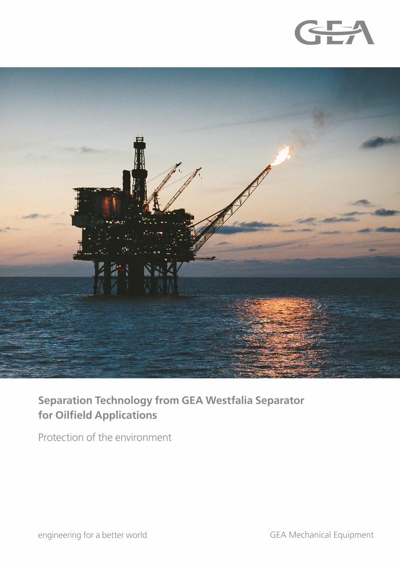
Separation Technology from GEA Westfalia Separator for Oilfield Applications
Protection of the environment
engineering for a better world GEA Mechanical Equipment
2
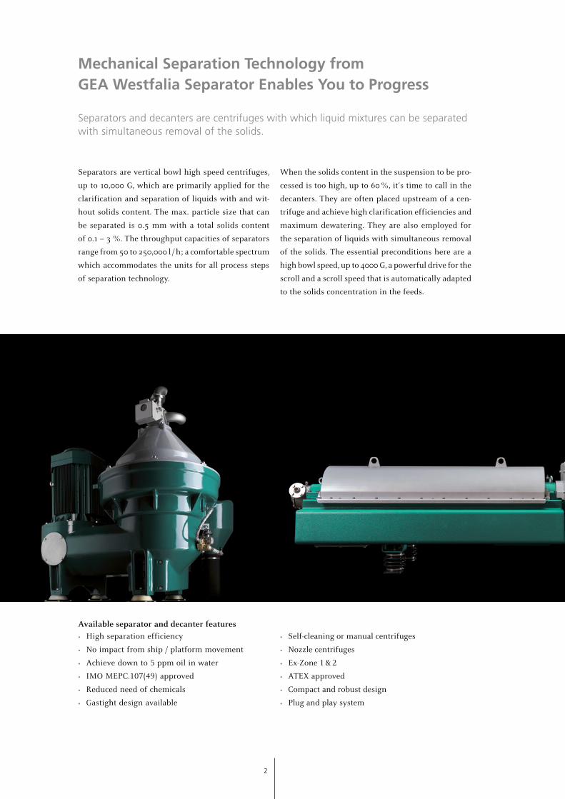
Mechanical Separation Technology from GEA Westfalia Separator Enables You to Progress
Separators and decanters are centrifuges with which liquid mixtures can be separated with simultaneous removal of the solids.
Separators are vertical bowl high speed centrifuges,
up to 10,000 G, which are primarily applied for the
clarification and separation of liquids with and wit-
hout solids content. The max. particle size that can
be separated is 0.5 mm with a total solids content
of 0.1 – 3 %. The throughput capacities of separators
range from 50 to 250,000 l / h; a comfortable spectrum
which accommodates the units for all process steps
of separation technology.
When the solids content in the suspension to be pro-
cessed is too high, up to 60 %, it‘s time to call in the
decanters. They are often placed upstream of a cen-
trifuge and achieve high clarification efficiencies and
maximum dewatering. They are also employed for
the separation of liquids with simultaneous removal
of the solids. The essential preconditions here are a
high bowl speed, up to 4000 G, a powerful drive for the
scroll and a scroll speed that is automatically adapted
to the solids concentration in the feeds.
Available separator and decanter features
• High separation efficiency
• No impact from ship / platform movement
• Achieve down to 5 ppm oil in water
• IMO MEPC.107(49) approved
• Reduced need of chemicals
• Gastight design available
• Self-cleaning or manual centrifuges
• Nozzle centrifuges
• Ex-Zone 1 & 2
• ATEX approved
• Compact and robust design
• Plug and play system
3
2 Mechanical Separation Technology
Separators and decanters
4 High Performance Equipment
Overview oilfield applications
5 Drilling
Mud / slop / drain water treatment system
Brine water treatment system
High performance decanter technology
9 Production
Crude oil dewatering and produced water de-oiling
11 Utilities
Self-cleaning separators for MDO / LO / 3 HFO treatment
12 Downstream Applications
MEG particle removal
Slop oil recovery
Cat fines removal
18 GEA Westfalia Separator minimaXx®
Hydraulic oil treatment plant
GEA Westfalia Separator ViscoBoosterUnit
Fuel oil conditioning system
19 GEA Westfalia Separator SeaWaterDistiller
Water desalination system
Contents
4
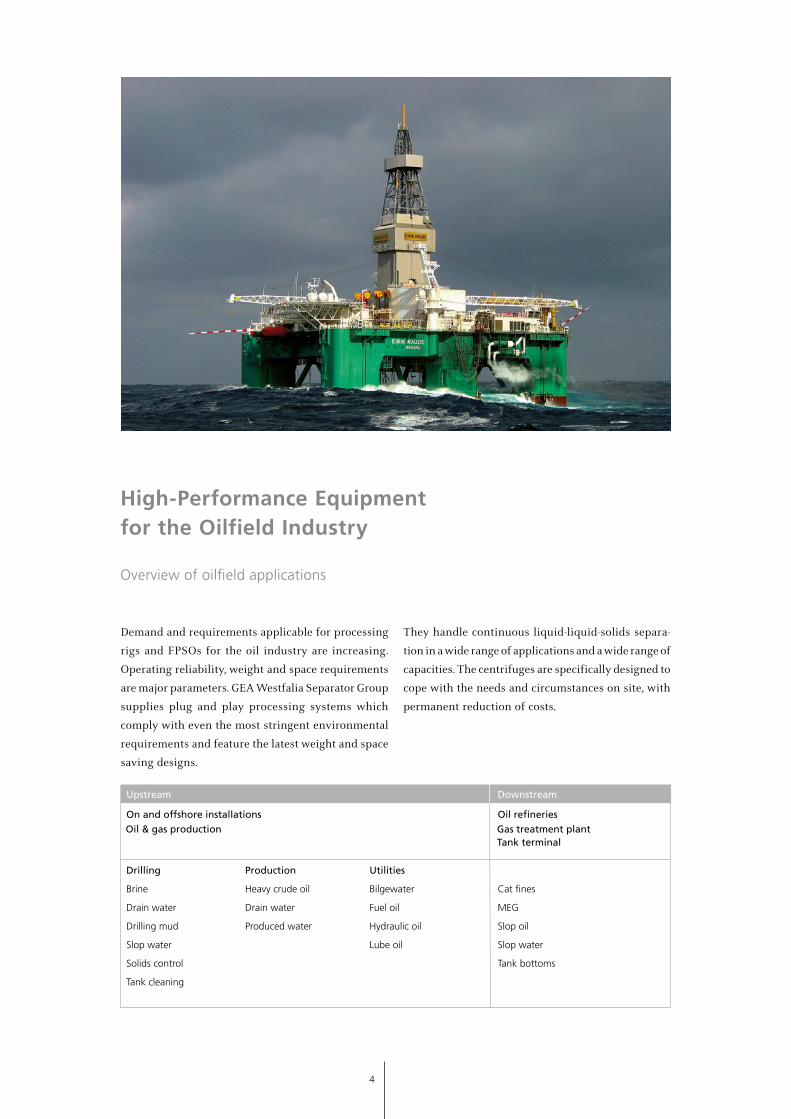
High-Performance Equipment for the Oilfield Industry
Overview of oilfield applications
Demand and requirements applicable for processing
rigs and FPSOs for the oil industry are increasing.
Operating reliability, weight and space requirements
are major parameters. GEA Westfalia Separator Group
supplies plug and play processing systems which
comply with even the most stringent environmental
requirements and feature the latest weight and space
saving designs.
They handle continuous liquid-liquid-solids separa-
tion in a wide range of applications and a wide range of
capacities. The centrifuges are specifically designed to
cope with the needs and circumstances on site, with
permanent reduction of costs.
Upstream Downstream
On and offshore installations Oil refineries
Drilling Production Utilities
Brine Heavy crude oil Bilgewater Cat fines
Drain water Drain water Fuel oil MEG
Drilling mud Produced water Hydraulic oil Slop oil
Slop water Lube oil Slop water
Solids control Tank bottoms
Tank cleaning
Oil & gas production Gas treatment plantTank terminal
5
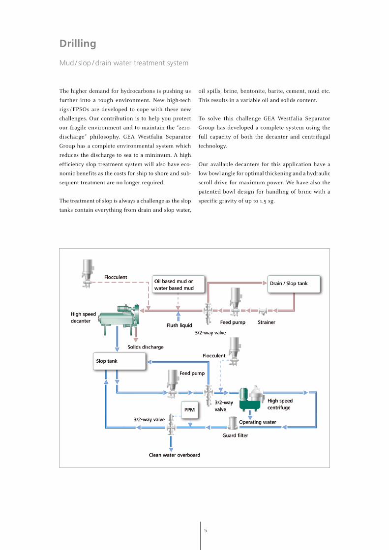
Drilling
Mud / slop / drain water treatment system
The higher demand for hydrocarbons is pushing us
further into a tough environment. New high-tech
rigs / FPSOs are developed to cope with these new
challenges. Our contribution is to help you protect
our fragile environment and to maintain the “zero-
discharge” philosophy. GEA Westfalia Separator
Group has a complete environmental system which
reduces the discharge to sea to a minimum. A high
efficiency slop treatment system will also have eco-
nomic benefits as the costs for ship to shore and sub-
sequent treatment are no longer required.
The treatment of slop is always a challenge as the slop
tanks contain everything from drain and slop water,
oil spills, brine, bentonite, barite, cement, mud etc.
This results in a variable oil and solids content.
To solve this challenge GEA Westfalia Separator
Group has developed a complete system using the
full capacity of both the decanter and centrifugal
technology.
Our available decanters for this application have a
low bowl angle for optimal thickening and a hydraulic
scroll drive for maximum power. We have also the
patented bowl design for handling of brine with a
specific gravity of up to 1.5 sg.
6
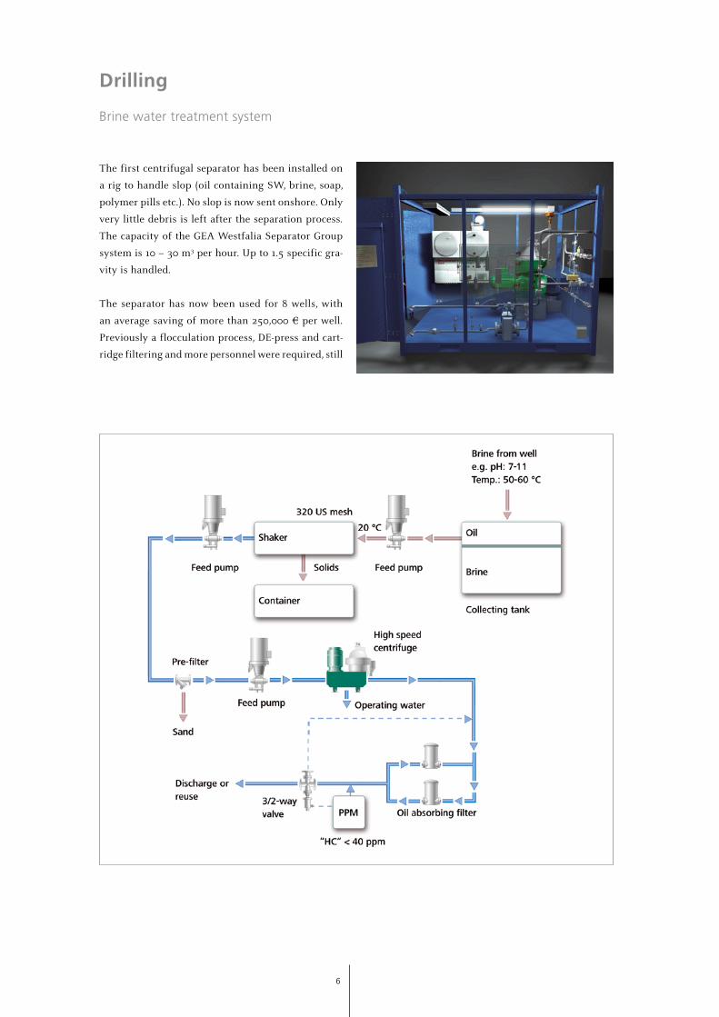
Drilling
Brine water treatment system
The first centrifugal separator has been installed on
a rig to handle slop (oil containing SW, brine, soap,
polymer pills etc.). No slop is now sent onshore. Only
very little debris is left after the separation process.
The capacity of the GEA Westfalia Separator Group
system is 10 – 30 m3 per hour. Up to 1.5 specific gra-
vity is handled.
The separator has now been used for 8 wells, with
an average saving of more than 250,000 € per well.
Previously a flocculation process, DE-press and cart-
ridge filtering and more personnel were required, still
resulting in larger volumes being sent onshore for
expensive disposal.
7
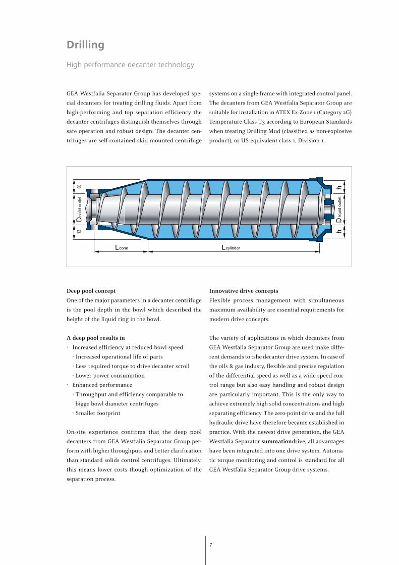
Drilling
High performance decanter technology
GEA Westfalia Separator Group has developed spe-
cial decanters for treating drilling fluids. Apart from
high-performing and top separation efficiency the
decanter centrifuges distinguish themselves through
safe operation and robust design. The decanter cen-
trifuges are self-contained skid mounted centrifuge
Deep pool concept
One of the major parameters in a decanter centrifuge
is the pool depth in the bowl which described the
height of the liquid ring in the bowl.
A deep pool results in
• Increased efficiency at reduced bowl speed
• Increased operational life of parts
• Less required torque to drive decanter scroll
• Lower power consumption
• Enhanced performance
• Throughput and efficiency comparable to
bigge bowl diameter centrifuges
• Smaller footprint
On-site experience confirms that the deep pool
decanters from GEA Westfalia Separator Group per-
form with higher throughputs and better clarification
than standard solids control centrifuges. Ultimately,
this means lower costs though optimization of the
separation process.
Innovative drive concepts
Flexible process management with simultaneous
maximum availability are essential requirements for
modern drive concepts.
The variety of applications in which decanters from
GEA Westfalia Separator Group are used make diffe-
rent demands to tshe decanter drive system. In case of
the oils & gas industy, flexible and precise regulation
of the differential speed as well as a wide speed con-
trol range but also easy handling and robust design
are particularly important. This is the only way to
achieve extremely high solid concentrations and high
separating efficiency. The zero-point drive and the full
hydraulic drive have therefore became established in
practice. With the newest drive generation, the GEA
Westfalia Separator summationdrive, all advantages
have been integrated into one drive system. Automa-
tic torque monitoring and control is standard for all
GEA Westfalia Separator Group drive systems.
systems on a single frame with integrated control panel.
The decanters from GEA Westfalia Separator Group are
suitable for installation in ATEX Ex-Zone 1 (Category 2G)
Temperature Class T3 according to European Standards
when treating Drilling Mud (classified as non-explosive
product), or US equivalent class 1, Division 1.
D liq
uid
outle
th
h
D so
lid o
utle
tα
α
L cone L cylinder
8
Drilling
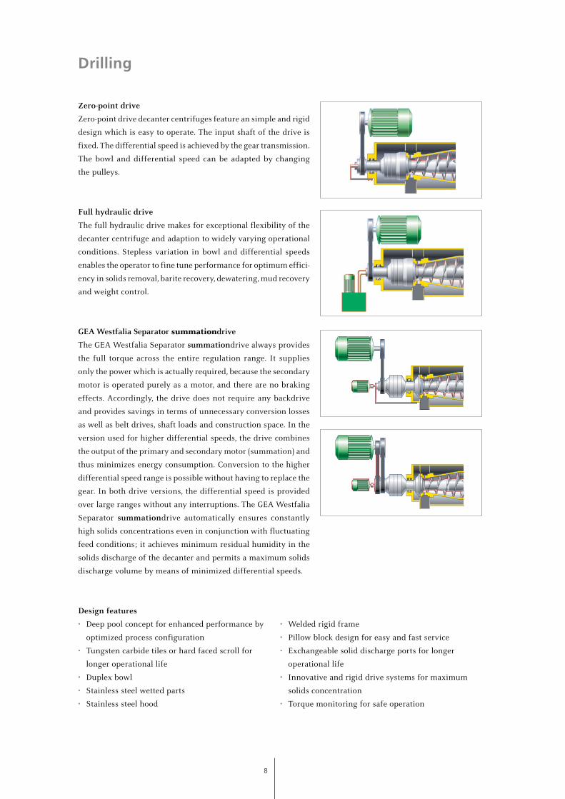
Zero-point drive
Zero-point drive decanter centrifuges feature an simple and rigid
design which is easy to operate. The input shaft of the drive is
fixed. The differential speed is achieved by the gear transmission.
The bowl and differential speed can be adapted by changing
the pulleys.
Full hydraulic drive The full hydraulic drive makes for exceptional flexibility of the
decanter centrifuge and adaption to widely varying operational
conditions. Stepless variation in bowl and differential speeds
enables the operator to fine tune performance for optimum effici-
ency in solids removal, barite recovery, dewatering, mud recovery
and weight control.
GEA Westfalia Separator summationdrive
The GEA Westfalia Separator summationdrive always provides
the full torque across the entire regulation range. It supplies
only the power which is actually required, because the secondary
motor is operated purely as a motor, and there are no braking
effects. Accordingly, the drive does not require any backdrive
and provides savings in terms of unnecessary conversion losses
as well as belt drives, shaft loads and construction space. In the
version used for higher differential speeds, the drive combines
the output of the primary and secondary motor (summation) and
thus minimizes energy consumption. Conversion to the higher
differential speed range is possible without having to replace the
gear. In both drive versions, the differential speed is provided
over large ranges without any interruptions. The GEA Westfalia
Separator summationdrive automatically ensures constantly
high solids concentrations even in conjunction with fluctuating
feed conditions; it achieves minimum residual humidity in the
solids discharge of the decanter and permits a maximum solids
discharge volume by means of minimized differential speeds.
Design features
• Deep pool concept for enhanced performance by
optimized process configuration
• Tungsten carbide tiles or hard faced scroll for
longer operational life
• Duplex bowl
• Stainless steel wetted parts
• Stainless steel hood
• Welded rigid frame
• Pillow block design for easy and fast service
• Exchangeable solid discharge ports for longer
operational life
• Innovative and rigid drive systems for maximum
solids concentration
• Torque monitoring for safe operation
9
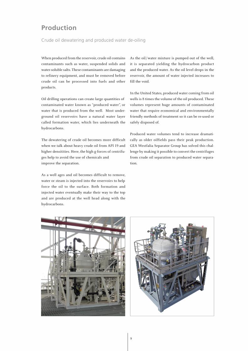
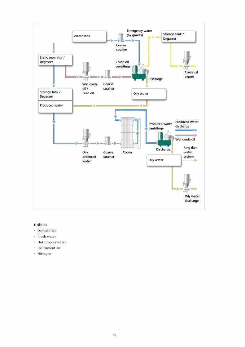
Production
Crude oil dewatering and produced water de-oiling
When produced from the reservoir, crude oil contains
contaminants such as water, suspended solids and
water-soluble salts. These contaminants are damaging
to refinery equipment, and must be removed before
crude oil can be processed into fuels and other
products.
Oil drilling operations can create large quantities of
contaminated water known as “produced water”, or
water that is produced from the well. Most under-
ground oil reservoirs have a natural water layer
called formation water, which lies underneath the
hydrocarbons.
The dewatering of crude oil becomes more difficult
when we talk about heavy crude oil from API 19 and
higher densitities. Here, the high g-forces of centrifu-
ges help to avoid the use of chemicals and
improve the separation.
As a well ages and oil becomes difficult to remove,
water or steam is injected into the reservoirs to help
force the oil to the surface. Both formation and
injected water eventually make their way to the top
and are produced at the well head along with the
hydrocarbons.
As the oil / water mixture is pumped out of the well,
it is separated yielding the hydrocarbon product
and the produced water. As the oil level drops in the
reservoir, the amount of water injected increases to
fill the void.
In the United States, produced water coming from oil
wells is 8 times the volume of the oil produced. These
volumes represent huge amounts of contaminated
water that require economical and environmentally
friendly methods of treatment so it can be re-used or
safely disposed of.
Produced water volumes tend to increase dramati-
cally as older oilfields pass their peak production.
GEA Westfalia Separator Group has solved this chal-
lenge by making it possible to convert the centrifuges
from crude oil separation to produced water separa-
tion.
10
Utilities
• Demulsifier
• Fresh water
• Hot process water
• Instrument air
• Nitrogen
11
Utilities
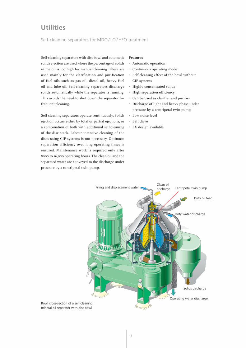
Self-cleaning separators for MDO / LO / HFO treatment
Self-cleaning separators with disc bowl and automatic
solids ejection are used where the percentage of solids
in the oil is too high for manual cleaning. These are
used mainly for the clarification and purification
of fuel oils such as gas oil, diesel oil, heavy fuel
oil and lube oil. Self-cleaning separators discharge
solids automatically while the separator is running.
This avoids the need to shut down the separator for
frequent cleaning.
Self-cleaning separators operate continuously. Solids
ejection occurs either by total or partial ejections, or
a combination of both with additional self-cleaning
of the disc stack. Labour intensive cleaning of the
discs using CIP systems is not necessary. Optimum
separation efficiency over long operating times is
ensured. Maintenance work is required only after
8000 to 16,000 operating hours. The clean oil and the
separated water are conveyed to the discharge under
pressure by a centripetal twin pump.
Features
• Automatic operation
• Continuous operating mode
• Self-cleaning effect of the bowl without
CIP systems
• Highly concentrated solids
• High separation efficiency
• Can be used as clarifier and purifier
• Discharge of light and heavy phase under
pressure by a centripetal twin pump
• Low noise level
• Belt drive
• EX design available
Bowl cross-section of a self-cleaning mineral oil separator with disc bowl
Filling and displacement water
Dirty oil feed
Dirty water discharge
Clean oil discharge
Solids discharge
Operating water discharge
Centripetal twin pump
12
Downstream Applications
MEG particle removal
Proper hydrate management is vital for all field
developments. For long dietance gas / condensate tie-
backs continuous injection of MEG (Mono Ethylene
Glycol) in a closed MEG loop is the preferred solution.
By using carbon steel production pipelines, corrosion
and corrosion inhibition strategy become important
issues. Although the presence of the MEG itself gives
a reduction of the pipeline corrosion rate, additional
means are almost always required to avoid unaccep-
table corrosion.
Even though alternatives for corrosion control like
pH adjustment, addition of a corrosion inhibitor or a
combination of the different alternatives are utilized,
the pipeline will corrode and large amounts of iron
ions will be formed. These iron ions, with other diva-
lent ions like calcium stemming from the produced
water, will enter the onshore plant. To prevent accu-
mulation, and subsequently precipitation and scaling
at unwanted locations, these ions must be handled
with precaution at the onshore plant.
The nature of a closed loop MEG system, where water
is continuously removed through conventional rege-
neration, requires a holistic approach to the challenge
of ion and particle control and handling. Input from
different disciplines like chemistry, corrosion, scaling,
salt precipitation and engineering must interact in
the design of the onshore plant, where the MEG is to
be regenerated.
Flexibility regarding particle removal utilizing centri-
fuges has been built into the closed loop MEG system.
The centrifuges can be run both up- and downstream
of the MEG regeneration units. The reason why the
base case solution is downstream the MEG regenerati-
on units, is that the main overall concern to the project
is high volumes of particles of a certain size present
in the Lean MEG being injected sub sea having the
ability to obstruct the injection devices. However, if
problems are encountered in the MEG regeneration
units that can be traced back to particles in the Rich
MEG, the centrifuges can be run upstream the MEG
regeneration trains.
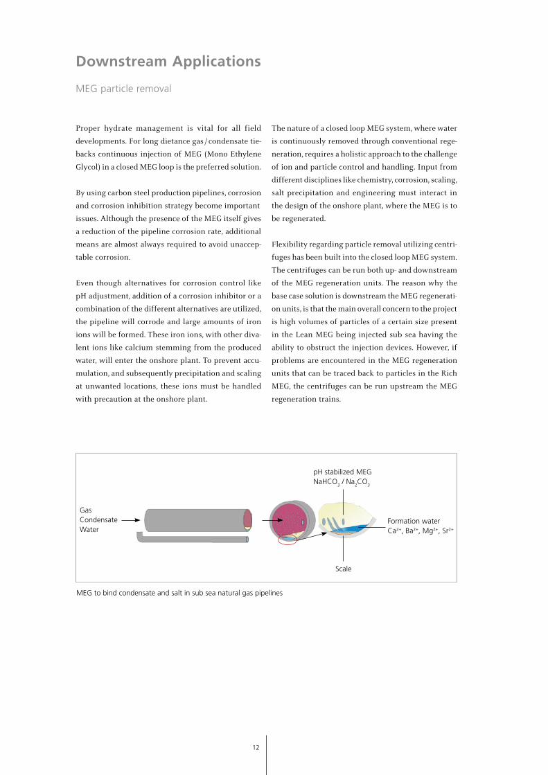
GasCondensateWater
Scale
pH stabilized MEGNaHCO3 / Na2CO3
Formation waterCa2+, Ba2+, Mg2+, Sr2+
MEG to bind condensate and salt in sub sea natural gas pipelines
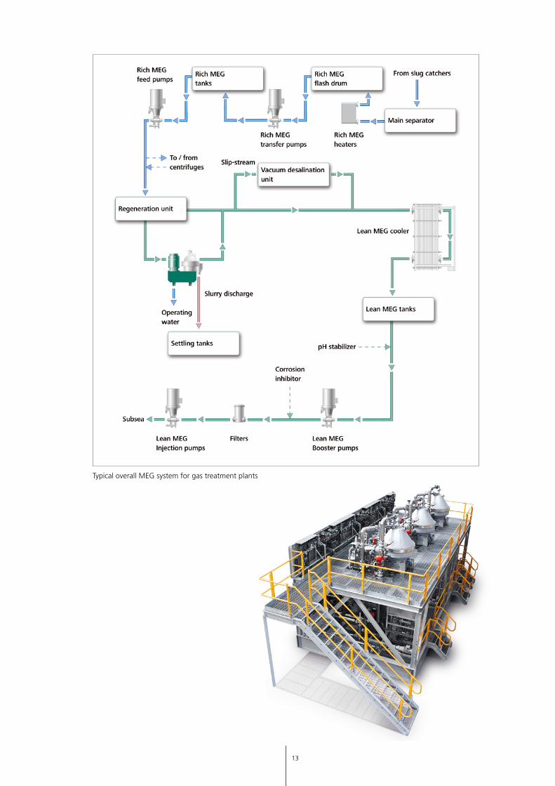
13
Typical overall MEG system for gas treatment plants
14
Downstream Applications
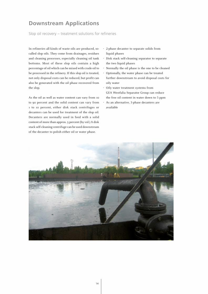
Slop oil recovery – treatment solutions for refineries
In refineries all kinds of waste oils are produced, so-
called slop oils. They come from drainages, residues
and cleaning processes, especially cleaning oil tank
bottoms. Most of these slop oils contain a high
percentage of oil which can be mixed with crude oil to
be processed in the refinery. If this slop oil is treated,
not only disposal costs can be reduced, but profit can
also be generated with the oil phase recovered from
the slop.
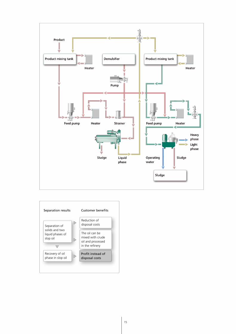
As the oil as well as water content can vary from 10
to 90 percent and the solid content can vary from
1 to 10 percent, either disk stack centrifuges or
decanters can be used for treatment of the slop oil.
Decanters are normally used in feed with a solid
content of more than approx. 5 percent (by vol.) A disk
stack self-cleaning centrifuge can be used downstream
of the decanter to polish either oil or water phase.
• 2-phase decanter to separate solids from
liquid phases
• Disk stack self-cleaning separator to separate
the two liquid phases
• Normally the oil phase is the one to be cleaned
• Optionally, the water phase can be treated
further downstream to avoid disposal costs for
oily water
• Oily water treatment systems from
GEA Westfalia Separator Group can reduce
the free oil content in water down to 5 ppm
• As an alternative, 3-phase decanters are
available
15
Separation ofsolids and twoliquid phases ofslop oil
Reduction of disposal costs
The oil can be mixed with crude oil and processedin the refinery
Recovery of oilphase in slop oil
Profit instead of disposal costs
Separation results Customer benefits
16
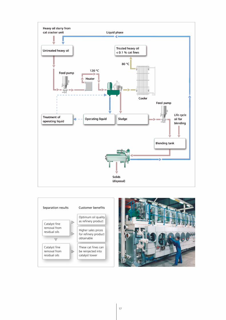
Downstream Applications
Systems for cat fines removal from residual oils in refineries
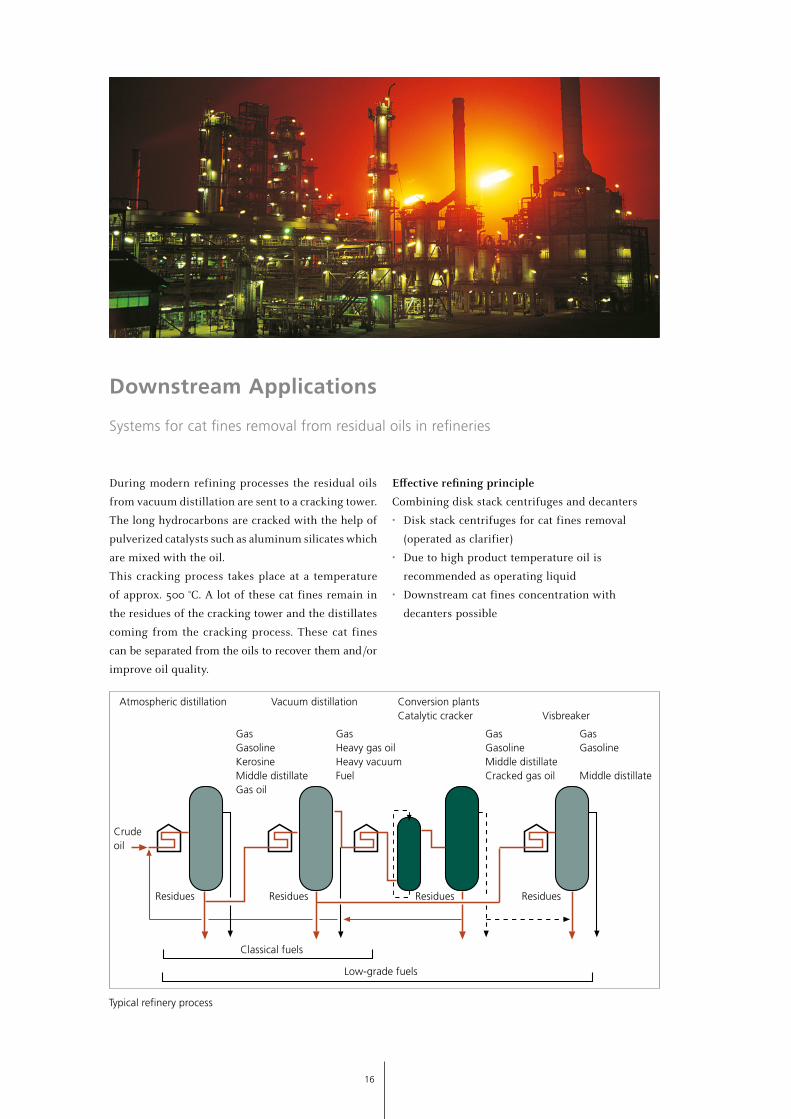
During modern refining processes the residual oils
from vacuum distillation are sent to a cracking tower.
The long hydrocarbons are cracked with the help of
pulverized catalysts such as aluminum silicates which
are mixed with the oil.
This cracking process takes place at a temperature
of approx. 500 °C. A lot of these cat fines remain in
the residues of the cracking tower and the distillates
coming from the cracking process. These cat fines
can be separated from the oils to recover them and /or
improve oil quality.
Effective refining principle
Combining disk stack centrifuges and decanters
• Disk stack centrifuges for cat fines removal
(operated as clarifier)
• Due to high product temperature oil is
recommended as operating liquid
• Downstream cat fines concentration with
decanters possible
Atmospheric distillation Vacuum distillation Conversion plantsCatalytic cracker Visbreaker
Crudeoil
Residues Residues Residues Residues
GasGasoline
Middle distillate
GasGasolineMiddle distillateCracked gas oil
GasHeavy gas oilHeavy vacuumFuel
GasGasolineKerosineMiddle distillateGas oil
Classical fuels
Low-grade fuels
Typical refinery process
17
Catalyst fine removal from residual oils
Optimum oil quality as refinery product
Separation results Customer benefits
Higher sales prices for refinery product obtainable
Catalyst fine removal from residual oils
These cat fines can be reinjected into catalyst tower
18
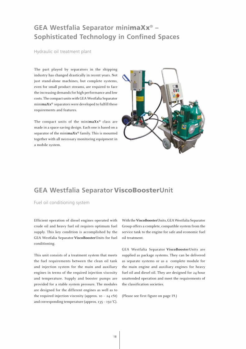
GEA Westfalia Separator minimaXx® –Sophisticated Technology in Confined Spaces
Hydraulic oil treatment plant
The part played by separators in the shipping
industry has changed drastically in recent years. Not
just stand-alone machines, but complete systems,
even for small product streams, are required to face
the increasing demands for high performance and low
costs. The compact units with GEA Westfalia Separator
minimaXx® separators were developed to fulfill these
requirements and features.
The compact units of the minimaXx® class are
made in a space-saving design. Each one is based on a
separator of the minimaXx® family. This is mounted
together with all necessary monitoring equipment in
a mobile system.
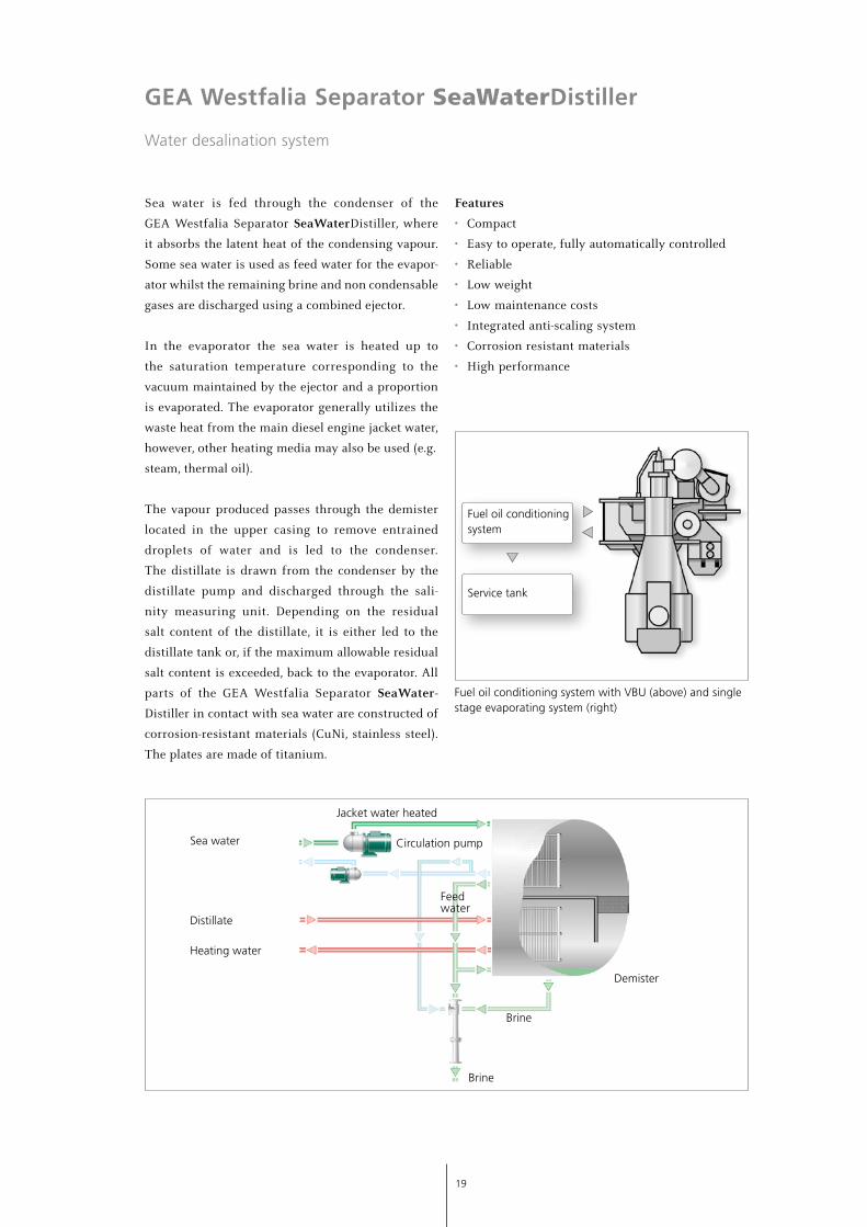
GEA Westfalia Separator ViscoBoosterUnit
Fuel oil conditioning system
Efficient operation of diesel engines operated with
crude oil and heavy fuel oil requires optimum fuel
supply. This key condition is accomplished by the
GEA Westfalia Separator ViscoBoosterUnits for fuel
conditioning.
This unit consists of a treatment system that meets
the fuel requirements between the clean oil tank
and injection system for the main and auxiliary
engines in terms of the required injection viscosity
and temperature. Supply and booster pumps are
provided for a stable system pressure. The modules
are designed for the different engines as well as to
the required injection viscosity (approx. 10 – 24 cSt)
and corresponding temperature (approx. 135 – 150 °C).
With the ViscoBoosterUnits, GEA Westfalia Separator
Group offers a complete, compatible system from the
service tank to the engine for safe and economic fuel
oil treatment.
GEA Westfalia Separator ViscoBoosterUnits are
supplied as package systems. They can be delivered
as separate systems or as a complete module for
the main engine and auxiliary engines for heavy
fuel oil and diesel oil. They are designed for 24-hour
unattended operation and meet the requirements of
the classification societies.
(Please see first figure on page 19.)
19
GEA Westfalia Separator SeaWaterDistiller
Water desalination system
Sea water is fed through the condenser of the
GEA Westfalia Separator SeaWaterDistiller, where
it absorbs the latent heat of the condensing vapour.
Some sea water is used as feed water for the evapor-
ator whilst the remaining brine and non condensable
gases are discharged using a combined ejector.
In the evaporator the sea water is heated up to
the saturation temperature corresponding to the
vacuum maintained by the ejector and a proportion
is evaporated. The evaporator generally utilizes the
waste heat from the main diesel engine jacket water,
however, other heating media may also be used (e.g.
steam, thermal oil).
The vapour produced passes through the demister
located in the upper casing to remove entrained
droplets of water and is led to the condenser.
The distillate is drawn from the condenser by the
distillate pump and discharged through the sali-
nity measuring unit. Depending on the residual
salt content of the distillate, it is either led to the
distillate tank or, if the maximum allowable residual
salt content is exceeded, back to the evaporator. All
parts of the GEA Westfalia Separator SeaWater-
Distiller in contact with sea water are constructed of
corrosion-resistant materials (CuNi, stainless steel).
The plates are made of titanium.
Features
• Compact
• Easy to operate, fully automatically controlled
• Reliable
• Low weight
• Low maintenance costs
• Integrated anti-scaling system
• Corrosion resistant materials
• High performance
Fuel oil conditioning system
Service tank
Jacket water heated
Sea water
Distillate
Heating water
Feedwater
Brine
Brine
Demister
Circulation pump
Fuel oil conditioning system with VBU (above) and single stage evaporating system (right)
The
info
rmat
ion
cont
aine
d in
thi
s br
ochu
re m
erel
y se
rves
as
a no
n-bi
ndin
g de
scrip
tion
of o
ur p
rodu
cts
and
is w
ithou
t gu
aran
tee.
Bin
ding
info
rmat
ion,
in p
artic
ular
rel
atin
g to
cap
acity
dat
a an
d su
itabi
lity
for
spec
ific
appl
icat
ions
, can
onl
y be
pro
vide
d w
ithin
the
fra
mew
ork
of c
oncr
ete
inqu
iries
. Prin
ted
on c
hlor
ine-
free
ble
ache
d pa
per
· Prin
ted
in G
erm
any
· Sub
ject
to
mod
ifica
tion
· Wes
tfal
ia®, W
estf
alia
Sep
arat
or ® a
nd m
inim
aXx®
are
reg
iste
red
trad
emar
ks o
f G
EA M
echa
nica
l Equ
ipm
ent
Gm
bH.
B_O
I-13-
05-0
014
EN
GEA Mechanical Equipment
GEA Westfalia Separator Group GmbH
Werner-Habig-Straße 1, 59302 Oelde, GermanyPhone: +49 2522 77-0, Fax: +49 2522 77-5058www.gea.com
GEA Group is a global engineering company with multi-billion euro sales and operations in more than
50 countries. Founded in 1881, the company is one of the largest providers of innovative equipment and
process technology. GEA Group is listed in the STOXX® Europe 600 Index.
We live our values.Excellence • Passion • Integrity • Responsibility • GEA-versity


