61
Copyright © SEL 2008 Power System Protection Fundamentals What should we teach students about power system protection?
| Date post: | 16-Jul-2015 |
| Category: |
Engineering |
| Upload: | luonglt |
| View: | 165 times |
| Download: | 0 times |

Copyright © SEL 2008
Power System Protection Fundamentals
What should we teach students about power system protection?

Copyright © SEL 2008
Agenda
Why protection is needed
Principles and elements of the protection system
Basic protection schemes
Digital relay advantages and enhancements

Copyright © SEL 2008
Disturbances: Light or Severe The power system must maintain acceptable
operation 24 hours a day Voltage and frequency must stay within certain
limits
Small disturbances The control system can handle these
Example: variation in transformer or generator load
Severe disturbances require a protection system They can jeopardize the entire power system
They cannot be overcome by a control system

Copyright © SEL 2008
Power System Protection
Operation during severe disturbances: System element protection
System protection
Automatic reclosing
Automatic transfer to alternate power supplies
Automatic synchronization

Copyright © SEL 2008
Electric Power System Exposure to External Agents

Copyright © SEL 2008
Damage to Main Equipment

Copyright © SEL 2008
Protection System
A series of devices whose main purpose is to protect persons and primary electric
power equipment from the effects of faults
The “Sentinels”

Copyright © SEL 2008
Blackouts
Loss of service in a large area or population region
Hazard to human life
May result in enormous economic losses
Overreaction of the protection system
Bad design of the protection system
Characteristics Main Causes

Copyright © SEL 2008
Short Circuits Produce High Currents
FaultSubstation
abc
I
IWire
Three-Phase Line
Thousands of Amps

Copyright © SEL 2008
Electrical Equipment Thermal Damage
I
t
In Imd
Damage Curve
Short-Circuit Current
Damage Time
Rated Value

Copyright © SEL 2008
Mechanical Damage DuringShort Circuits
Very destructive in busbars, isolators, supports, transformers, and machines
Damage is instantaneous
i1
i2
f1 f2
Rigid Conductors f1(t) = k i1(t) i2(t)
Mechanical Forces

Copyright © SEL 2008
The Fuse
Fuse
Transformer

Copyright © SEL 2008
Protection System Elements
Protective relays
Circuit breakers
Current and voltage transducers
Communications channels
DC supply system
Control cables

Copyright © SEL 2008
Three-Phase Diagram of the Protection Team

Copyright © SEL 2008
DC Tripping Circuit

Copyright © SEL 2008
Circuit Breakers

Copyright © SEL 2008
Current Transformers
Very High Voltage CTMedium-Voltage CT

Copyright © SEL 2008
Voltage Transformers
Medium Voltage
High Voltage
Note: Voltage transformers are also known as potential transformers

Copyright © SEL 2008
Protective Relays

Copyright © SEL 2008
Examples of Relay Panels
Old Electromechanical
Microprocessor-Based Relay

Copyright © SEL 2008
How Do Relays Detect Faults? When a fault takes place, the current, voltage,
frequency, and other electrical variables behave in a peculiar way. For example: Current suddenly increases
Voltage suddenly decreases
Relays can measure the currents and the voltages and detect that there is an overcurrent, or an undervoltage, or a combination of both
Many other detection principles determine the design of protective relays

Copyright © SEL 2008
Main Protection Requirements Reliability
Dependability
Security
Selectivity
Speed System stability
Equipment damage
Power quality
Sensitivity High-impedance faults
Dispersed generation

Copyright © SEL 2008
Primary Protection

Copyright © SEL 2008
Primary Protection Zone Overlapping
ProtectionZone B
ProtectionZone A
To Zone BRelays
To Zone ARelays
52 ProtectionZone B
ProtectionZone A
To Zone BRelays
To Zone ARelays
52

Copyright © SEL 2008
Backup Protection
AC D
E
Breaker 5Fails
1 2 5 6 11 12
T
3 4 7 8 9 10
B F

Copyright © SEL 2008
Typical Short-Circuit Type Distribution
Single-Phase-Ground: 70–80%
Phase-Phase-Ground: 17–10%
Phase-Phase: 10–8%
Three-Phase: 3–2%

Copyright © SEL 2008
Balanced vs. Unbalanced Conditions
Balanced System Unbalanced System
cI
aI
bI
aI
cI
bI

Copyright © SEL 2008
Decomposition of an Unbalanced System

Copyright © SEL 2008
Power Line Protection Principles
Overcurrent (50, 51, 50N, 51N)
Directional Overcurrent (67, 67N)
Distance (21, 21N)
Differential (87)

Copyright © SEL 2008
Application of Inverse-Type Relays
tRelay Operation Time
I
Fault Load
Radial Line

Copyright © SEL 2008
Distance
Distance
t
I
} } }T∆
Inverse-Time Relay Coordination
T∆ T∆

Copyright © SEL 2008
Addition of Instantaneous OC Element
tRelay Operation
Time
I
Fault Load
Radial Line

Copyright © SEL 2008
50/51 Relay Coordination
Distance
Distance
t
I
} } }T∆ T∆ T∆

Copyright © SEL 2008
Directional Overcurrent ProtectionBasic Applications
K
L

Copyright © SEL 2008
Directional Overcurrent ProtectionBasic Principle
F2
Relay
F1
Forward Fault (F1)Reverse Fault (F2)
V
IV
I
IV

Copyright © SEL 2008
Overcurrent Relay Problem
11 )8.0( LSSETTING ZZ
EI
+≈
11)( )8.0( LS
LIMITFAULT ZZE
I+′
=
Relay operates when the following condition holds:
SETTINGaFAULT III >=
As changes, the relay’s “reach” will change, since setting is fixed
1sZ

Copyright © SEL 2008
Distance Relay Principle
Three-Phase Solid Fault
d
L
RadialLine21
Suppose Relay Is Designed to Operate When:
||||)8.0(|| 1 aLa IZV ≤
cba III ,,
cba VVV ,,
Copyright © SEL 2008
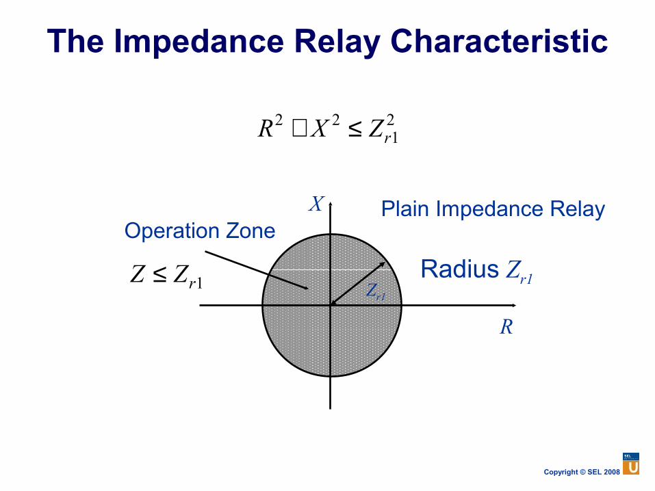
The Impedance Relay Characteristic
21
22rZXR ≤+
R
X Plain Impedance RelayOperation Zone
Zr1
Radius Zr11rZZ ≤

Copyright © SEL 2008
Need for Directionality
1 2 3 4 5 6
F1F2
R
XRELAY 3Operation Zone
F1
F2Nonselective Relay Operation

Copyright © SEL 2008
Directionality Improvement
1 2 3 4 5 6
F1F2
R
XRELAY 3Operation Zone
F1
F2The Relay Will Not Operate for This Fault
Directional Impedance Relay Characteristic

Copyright © SEL 2008
Mho Element Characteristic (Directional Impedance Relay)
( )MTMZZ ϕϕ −≤ cos
( )MTMZIV ϕϕ −≤ cosOperates when:

Copyright © SEL 2008
Three-Zone Distance Protection
1 2 3 4 5 6
Zone 1
Zone 2Zone 3
Time
TimeZone 1 Is Instantaneous

Copyright © SEL 2008
Line Protection With Mho Elements
E
X
RA
B
C
D

Copyright © SEL 2008
Circular Distance Relay Characteristics
MHO
OFFSETMHO (1)
PLAIN IMPEDANCE
R
X
R
X
R
X
OFFSETMHO (2)
R
X
LENS(RESTRICTED MHO 1)
TOMATO(RESTRICTED MHO 2)
R
X
R
X

Copyright © SEL 2008
Semi-Plane Type Characteristics
REACTANCE
OHM
DIRECTIONAL
R
X
R
X
R
X
RESTRICTEDDIRECTIONAL
R
X
RESTRICTEDREACTANCE
QUADRILATERAL
R
X
R
X

Copyright © SEL 2008
Distance ProtectionSummary
Current and voltage information
Phase elements: more sensitive than 67 elements
Ground elements: less sensitive than 67N elements
Application: looped and parallel lines

Copyright © SEL 2008
Directional ComparisonPilot Protection Systems

Copyright © SEL 2008
Permissive OverreachingTransfer Trip

Copyright © SEL 2008
Basic POTT Logic
Zone 2 Elements
RCVR
Key XMTR
TripAND

Copyright © SEL 2008
Directional ComparisonBlocking Scheme

Copyright © SEL 2008
Basic DCB Logic
Zone 2
RCVRTrip
CC
0
Carrier Coordination
Time Delay
Key XMTRZone 3

Copyright © SEL 2008
Differential Protection Principle
No Relay Operation if CTs Are Considered Ideal
ExternalFault
IDIF = 0
CT CT
50
Balanced CT Ratio
ProtectedEquipment

Copyright © SEL 2008
Differential Protection Principle
InternalFault
IDIF > ISETTING
CTR CTR
50
Relay Operates
ProtectedEquipment

Copyright © SEL 2008
Problem of Unequal CT Performance
False differential current can occur if a CT saturates during a through-fault
Use some measure of through-current to desensitize the relay when high currents are present
ExternalFault
ProtectedEquipment
IDIF ≠ 0
CT CT
50

Copyright © SEL 2008
Possible Scheme – Percentage Differential Protection Principle
ProtectedEquipment
ĪRĪS
CTR CTR
Compares:
Relay(87)
OP S RI I I= +
| | | |
2S R
RT
I Ik I k
+× = ×
ĪRPĪSP

Copyright © SEL 2008
Differential Protection Applications
Bus protection
Transformer protection
Generator protection
Line protection
Large motor protection
Reactor protection
Capacitor bank protection
Compound equipment protection

Copyright © SEL 2008
Differential ProtectionSummary
The overcurrent differential scheme is simple and economical, but it does not respond well to unequal current transformer performance
The percentage differential scheme responds better to CT saturation
Percentage differential protection can be analyzed in the relay and the alpha plane
Differential protection is the best alternative selectivity/speed with present technology

Copyright © SEL 2008
Multiple Input Differential SchemesExamples
Differential Protection Zone
Bus Differential: Several Inputs
ĪRPĪSP
OP
ĪT
I1 I2 I3 I4
Three-Winding TransformerDifferential: Three Inputs

Copyright © SEL 2008
Advantages of Digital Relays
MultifunctionalCompatibility withdigital integrated
systems
Low maintenance(self-supervision)
Highly sensitive,secure, and
selectiveAdaptive
Highly reliable(self-supervision)
Reduced burden on
CTs and VTs
ProgrammableVersatile
Low Cost

Copyright © SEL 2008
Synchrophasors Provide a “Snapshot” of the Power System

Copyright © SEL 2008
The Future Improvements in computer-based
protection
Highly reliable and viable communication systems (satellite, optical fiber, etc.)
Integration of control, command, protection, and communication
Improvements to human-machine interface
Much more


