57
AD-A139 972 A NEW DISTRIBUTED ROUTING PROTOCO(U) ARMY COMMONICATIONS-ELECTRONICS COMMAND FORT MONMOUTH NJ R dKIMET AL dAN 84CECOM-TR84- UJNCLASSIFED F/ G91 4 EEEmohEEE.mEoE EomhhhEEEEohEEE

AD-A139 972 A NEW DISTRIBUTED ROUTING PROTOCO(U) ARMYCOMMONICATIONS-ELECTRONICS COMMAND FORT MONMOUTH NJR dKIMET AL dAN 84CECOM-TR84-
UJNCLASSIFED F/ G91 4
EEEmohEEE.mEoEEomhhhEEEEohEEE

111Lis 11.2
1111U 1.0
1.25 1 1. II1.
MICROCOPY RESOLUTION TEST CHARTNATIONAL BUREAU Of STANDARDS- 163-A

RESEARCH AND DEVELOPMENT TECHNICAL REPORTCECOM -TR-84-1
A NEW DISTRIBUTED ROUTING PROTOCOL
CRICHARD J. KIMr-1q ISRAEL MAYK
CENTER FOR SYSTEMS ENGINEERING & INTEGRATION
JANUARY 1984
DISTRIBUTION STATEMENT
Approved for public release;distribution is unlimited.
09
CECO
O S Ay COMMONICATISS-ELECTRONICS COMMAND
FORT MINITI, NEW JERSEY 07703
64 04 10 035

I
WOTICES
Disclaimers
The citation of trade names and names of mautwctint....this report is not to be construed a" official Goverumentindorsement or approval of commercial prxductu or services
referenced herein.
Disposition
Destroy this report when it is no longer needed. Do notreturn it to the originator.
1bi)*

UNCLAAIFTEDSECURITY CLASSIFICATION OF THIS PAGE (When Dat Enterd)
READ INSTRUCTIONSREPORT DOCUMENTATION PAGE 1BEFORE COMPLETING FORM
I REPORT NUMBER 2. T AC SiO-O PIENT'S CATALOG NUMBER
CEcom-TR-84-1 i~I'f/7~S. TITLE (ad Sub.i.) S. TYPE OF REPORT & PEFIOD COVERED
Technical ReportJune 1983 - Jan 1984
A NEW DISTRIBUTED ROUTING PROTOCOL 6. PERFORMING ORG. REPORT NUMBER
7. AUTHOR(*) 0. CONTRACT OR GRANT NUMBER(a)
Richard J. Kim
Israel Mayk
S. PERFORMING ORGANIZATION NAME AND ADDRESS 10. PROGRAM ELEMENT, PROJECT, TASKAREA & WORK UNIT NUMBERS
US Army Communications-Electronics CommandCenter for Systems Engineering & Integration
ATTN: DRSEL-SEI-F, Fort Monmouth, NJ 07703
11. CONTROLLING OFFICE NAME AND ADDRESS 12. REPORT DATE
January 1984Same as above Is. NUMBER OF PAGES
14. MONITORING AGENCY NAME & ADDRESS(If different from Controlling Office) IS. SECURITY C.ASS. (of fhia report)
MCASIFIED
- So. OECL ASSI FICATION/ DOWNGRADINGSCHEDULE
16. DISTRIBUTION STATEMENT (of thin Report)
Approved for public release; distribution is unlimited.
17. DISTRIBUTION STAT EMENT (of the abstract enroed In Dlock 20. It dilient om JRewott)
IS. SUPPLEMENTARY ,OTES
r
19. KEY WORDS (Conlit . an reverse side if necessry ad identify by block numbr)
Distributec Routing, Network, Connectivity
AWsrRACr (Cotaw an levsene de it ooeem a"ad Identify by block ntaniber)
" Research was conducted in the area of distributed routing of messages in a
digital broadcast network.
The early detection routing protocol (EDRP) was developed to achieve
automated shortest-path routing and optimum resource distribution.
EDRP can be implemented either on a real time basis or as a networksimulation tool for the network manager.
D) W3m CW [TION OFr I MOV 6 S GDWLTMrS , 0S E 0 NTUNCLASSIFIED
SECURITY CLASSICATION OF THIS PAGE (WIbm Dae Entered)

UNCLASSIFIEDcVmiV CIFUM Vn OP THIS PAGR(b.on 08aolm"
EDRP works as fllows: A minimum spanning tree is grown from a message
origination point (source) until the message destination po.,.t (sink) is
found. The ?ath between the source and the sink within the minimum
spanning tree is the shortest path between the two points.
A graphics simulation program was developed to test the protocol. For
each tested network, minimum-hop path routing and congestion control were
demonstrated.
ITNQLARqTFI1fl
aCumITy CLASSIFICATION OP THIS PAGC(Iegn DMS nfetoe)
- - - --... - .

II
'V ~section
1.0 oC ..................... 11.1 eedlim ...................... 11.2 Connectivity ............ 21.2.1 A disaoiected retwork ............ 31.2.2 Spar oonmecLivity ........... 31.2.3 crDc.ivity qtality .............. 41.2.4 Asymmetric connectivity ........... 52.0 ISSJFS IN DIST'RIWETD FROTiM ....... 72.1 Failsafe rzuting .................. 72.2 Message volume .................... 92.Neok zesponse te ............. 113.0 BSIC ROFIg Pm .............. 133.1 LJirk cst ............. ........ 133.2 GraIb tizary and routing ........... 163.2.1 Minimum ttal brandh cost problem . Ii3.2.2 Minm path ost prxl ........ 193.3 Hop leeLJ ................. ... 213.4 ]Lti gj list. ..................... 263.5 Foting failu ................. 273.6 Multiple medIlims fro a n
ource ................... 273.7 S ltamos o oenae oE minm
qms dng t .mes............... 273.8 B simulatim zsWdts ..... 284.0 EMY i (1EcON PIUTIIG PK7KXL 324.1 Cmeacain t.atw, (lev1l 0)
wa .. ........................... 324.2 *ruidral ammaccivity trix ...... 334.3 Emly drte im ... .... . ......... 354.3.1 First leel early dtotian o..... 354.3.2 SaxwI lewi early teck -.... 354.3.3 Early drt.ct Im alqjritb. .......... 364.4 EJ slakuulatkn mults ........... 375.0 CAEJIG o.......................... 43. . . ........ .... ... 43 I
.... . . . .. . . . .. .. 44
MW Graphics Simulatio.. .... 45Uff OF AIRCW .................. 47
iii .
. . . . . ... . .. .. .. . ... . . . .. ... ... . .. . . .. . .. .. .

FIGURS
Figure Pg
1-1. Discogm cted r k ....................... 31-2. Sparsely ommected tok ................. 31-3. Route between nodes A and D ................ 41-4. Undixected lirk ............................ 51-5. Directed lirk .............................. 52-1. Linear ntwk of 3 nodes ...................... 83-1. A siule rauting pnmk ................... 153-2. Mininum total brandh cont
algoritlu graphics output ................ 183-3. Mininum path wint alqzhrlt.
graphics output .......................... 83-4. Ievel I pleagation ........................ 213-5. Level 2 1ropagaton ........................ 213-6. Decision p euim at tie mo. ............... .43-7. Decision prooms at a prhWku1 arb ...... 253-8. 3-m&e limar mt-o, .................... .23-9. 7-nod t ............................ 213-10. 4-node linar retk ...................... .13-11. tecft connect ivity ...................... 293-12. BMW siulation output fcr 6 mmndlIm ...... IN3-13. IW simulation output fcr 3 men im ...... M4-1. 3-rode limar netwck ...................... 324-2. A ternnml connctivity mtrix ............. 344-3. A Nmvttan rak ........................ 384-4. EW grhim oututL fcr a NItahi
Ir .. ....................... 34-5. tz counecivity ...................... 494-6. MW graphics odut for a raznkm
deplymn ornmts.......................414-7. PMW graphics otput far a zutuke
deplynlt t nxdes ..................... 42
iv

Table pa
1-1. Hades vs. reedliis ............ 23-1. Hcps reqigpied fcw eadi muite ......... 2143-2. Capacity distarm table 1........... 143.-3. Cqpacity diStazm table ........... 234-1. Ccuuunicant status (level 0) maages .... 32
AcceSsion For
MCI C T;.3
U%-- lw--mcad

A MW DSTRIH LM g1UTfl1 P7OEOXL
leseardh is being onducted at the Center for System Eniginering andItegration of CHOK Fort Monmouth, WJ, to develop a d routingarid rescure allocation protowl for use in digital radio broastimtwks. Altho g the origiral notitian for the muearch was to delopa new distributed routing pro ml for real time use to adhieve autmtedshvtest-path ruting and oplimz resource distribtion in a battlefielddata distribion system, the research effot has evolvd into cbwlqplgeffei cputer assisted capabilities and tedudques fxr use by the&It k uavoger. to prest goal of our ongoig resarch is to eplan the
possibility of -eeting the baseline for the computer assisted ambIit4u.and techniques referred to in the corcding section of the Joint TactimiI n ton Distribution System Planning Guide [13.
This chapter introuxes the rader to the two basic kattlefield datadistributio system oncpts: ommunicton zedLizes and Mamockconnectivity. The parameters and thestab shed protoools that w will bedealing with are those of a typical battlefield data distributiax stemcomidemd for future dplomert.
I.1 Needlives
A iwedline is a directed (on w) virtual lik required betwen a assmageorigination poirt (sourcm) aid a mssage destination point (sink).Cm(upting the maxium nmber of reedliras pc sible in a zabtork inequile tn to compting the mzinmn anster of dixected virtual litkspossible in a rabaick of nodes.
A retwzk cn he =pres nted bV an undircted graph G(VE) %hers V is a setcf ertims (or nodes) and E is a set of edges (or udirected liks). Ifthaream two ertices in V, an edge is possible in 2, aid if them axethmee rtics In V, it Is possible to have up to 3 edges in 3. The ma inmmamber of possible edges in E givn V is equialernt to the total uber ofpaivise combinstis of the vertics in V. Therefore,
the .zain umber of possible edges 2 ~ nl/(n-2)121 = n(n-l)/2.
(An edge represents an undirected lirk, or equivalently, two directed lirksdirected in opposite directioma.) Wle can coxlude by subAtitution thatthe am n(n-l) nmadlim possible in any given nm tk requiring
-dlIl li-."III . . l|,

10 90Im 990
10_________________ 999 0
Table 1-1. Nodes vs. Maedlizas
The vaximm riutir of possible reedlins fbr a given zetwork can betabulated. Table 1-1 shos a quadratic increase in the =ziz umber ofpossible reedlims with respect to a linear increase in the nunber of nodesPresent.
In typical ilitary applications we find an average of 3 to 5 meedliuesassociated with a node. This is due to the hierarcical itecture ofcnesarc anr xxtol where typically 3 to 5 sbordinate units acrtilycomunicate with a conterd and control center.
1.2 Comectivity
Under the ideal conditiom of procpaatin in free ad a no physimiutzructions, lire-of-sight cperatiom are possible be n all pas of
nodes. fowevr, when nodes are tactically deployed in an eiixmimt withirregular terrain ad derve foliage. large signal attenuation (tyypimy140M @25Nn) and ccuplete outages (los of line-of-eight) can b eqs~ ad.
Relays are required to route masages vken a direct lirma -sicjht qpasutimis unrealizable. A rode can serv as a rmlay if them existA alirm-of-sight to the node. Howver, theme axe lire-of-sicwt oomractommwhich haw high sessage error rates de to ezwJxruaftal m mtt . "amare also lirm-of-si*t co t metir to n 1 1 po:,semsu hi4th semmap ,las.As we can see, all lie-of-eight corimctims cawnt be m Mn to beequal in deciding the best path to satisfy a medlim, mud ti. variatms Inthe parausters ast be taken into acunt.
metwol comnectivity influences the retwk cmpacity msquimmut, the rAthat Is taken to satisfy a medlir, and the llomllbod of a MWuiM beiaesatisfied. Therefore, mtk connectivity is an ispxxtaft p eter tWneeds to be quentified.
Silvester aid KlMirodc [91 defirm the degree ef a nam as the noter atcamunicants of the node. But they also define a rel as a comm atitself. e will sieply define the degree of a node as the nmttr ofcommunicsnts of the roe, not. ounking itself as its monsicaft. Its
2

degree of a node is defired as the total nt aer of edges (or arcs) whichcouple the rod to the retwk.
Ilpresemting a retwork by the undirected graph G(VoE), the axerage degreefor a retwok is the nmber of edges in E divided by the nmber of verticsin V, or average degree = Fedges/wrtex]. The awrage degree gives aniUdicstin of the onmctivity of the retwork.
A radio rtw rk operating in a heavily vegetated enviromamt is likely to besparsely onrected, and the sparse ommectivity may be reflected by a kwaerage degree. There are save wry ixportant problem in sudhan environment. The rext two section inwstigete the problem associatedwith sparsely comected netwks.
1.2.1 A N e etwortk
Figure 1-]. DisN
A retwcrk in which ewry node is cnrcted to at least oe other node is notnecessarily fully ammected. In Fig. ]-1 we see a n etwuk ofsix rodes, each node possessing a degree of 2. COUmnicatia b-amen thenmo&s in the qxup [AB.C] and the nodes in the group [DE,F] ame notfeasible. In gareral, given a fi~md aveage d"je, the pzdabilty of adisciected utwk o ring inmeases with the irizease in the tmber ofi n the rwk.
1.2.2 Sp e Comectivity
Figure 1-2. Sauly Cmzxucted netwczk<5I

A netwrk qerating in an environment of varying terrain anditimx my hwmlocal variations in its netk onnectivity. The nodes opeating in areasof sparse orectivity iay erounter prdblets of bottlerecking.
The netwk in Fig. 1-2 is fully comnected because each node can bae a pathto any other node. However, all communicatios btwen nodes A,B,C,ard Dand noes E,FG,and H must occur through ]irk I whidh mrcts nudes B andH. Lixk 1 is wbere bottlerecking is likely to occur. A pousibe solutionto the prdblem is to provid a lira-of-sigbt operation betwen nodes A andE, and between nodes C and G.
1.2.3 Comnectivity Quality
The connectivity quality (OC)) of a lirk is represented by an *-ary XD symbolwhidh requires a field of log2(M) bits. To enable the exchange of a largermuber of (D's with rinimm overhead capacity, M mist be a small nutar.Letting 1=4, only 2 bits per directed link are required, for which we asstmthe follc, ing qualification:
0 = very high prctability of trarnmission errorI = bigh probability of transmission error2 = medium prcbtbility of transmission erro3 = low prokability of tra ission error.
Figure 1-3. Rcate Between Nodes A and D
Suppose there is a reed to transuit one hundred message blodcks from node Ato nd D. The route chosen to satisfy the reed is illustrated in Fig. 1-3.The connectivity qualities of interest are
CX(AB) = 3 CX(BC) = 2 CW(C,D) = 1
for widh we assume the following quantification:
CD(i, ) = 3 implies Pe <IloCD(i, j) = 2 implies Pe < 20CD(i, J) = I implies Pe < 4000(i,j) = 0 implies Pe <he absence of CD(i,j) in a message implies Pe > 60
4,4
-i4

The pr&.bility that the trarumission fro- nod A to node D isucssful
is:
Pc = (1.0 - 0.1) x (1.0 - 0.2) x (1.0 - 0.4) = 0.432
Assuntiri a perfect back harel and that autcuatic repeat requests accuroMly at Ressage destination points (no& D in this exaple), it takes anaverage of 236 message blocks to deliver 1 correct nessage blodcs througha dceiml that has 0.568 prcbability of transmission encr. Naturally, withan imperfect back chanel, this ramber %xzld be higher.
1.2.4 Asymmetric Omnectivity
Ftr distrbted digital radio netwcs, the coriwctivity of a node-to-nodeciaomecti crnuat be assumd to be synmetric. There are two diffenert csesthat illustrate this point:
Cose I
3
2
Figure 1-4. Undirected Lirk
Ftw the retwirk i Fig. 1-4, link A-B is an undirected lirk, but theommctivity quality ((A,B) is 2 and the connectivity quality CQ(B,A) is 3.
The lirk. ten, is an urirected link with asymmetric cx +ivityqualities. The asymmetry an be due to ureqUal tranwi Pa rs,different arterma heights and/or directivity, and urequal proximtzes ofmkbe A and B to a wide %wriety of interferers.
Ce 2:
Figure 1-5. Directed Lirk
Pbw the retwczk in Fig. 1-5, the conmectivity quality D(A,B) is 3. but
51

C(XBA) is abaert in the (direct) cmxounicart status mesages. Theeftze,we can say that the li& in a directed limk widi allntm a~amcticre onlyfrcui node A to ruxl B.
6

2.6 LSSJE IN DISrRIBLaiD bCstIa
A variety of netwrk control schme (oentzalimed, hierarchical, and fullydistributed) can te used in a digital brodcat retwork, but fow edmumdsurvivability under battlefield oodiitiom a distributed network cotral
de is considered.
Some distributed rcuting sdhmes hae been pxzwn very successful ingovrnmet and omercial aplications (RPI , slatted AILM, etc.), bitbemuse of mirius constraints associated with a digital breadmst metwrkmany puter oriented distribed rcuting algoritm are mt applicable foruse in battlefield data distribution jutm. The algrxitem; that am beiugstudied for applicability to the nrtwrk marpment of a kattlefield datadistribution system am the 3erlin-6 aU protomz , Bzamule-Imyk algorittmand zeprmulgation relay routing.
This chapter investigstes the vrious issues in dietxibzted routing. Thethree key issues whidh we will inestigmte are: failase zaiting,mdization of control messages, and i proving the ntwork respone time.We will eiplore these issues by citing the key prqpertim of the wriamjalgorithem last vntioned.
2.1 W isafe Rztn
The MITRE report, "A Survy of Routing Algoritbm for Dis-rihied DigitalRadio Nletwks" [2), states that:
I ) "A comon type of algoritm uses a distance matrix at each .....
2) "At times specified by the particular sche used, a mode mnd toits rmihbors its minm distance table, in whole or in part.The migbozr uses this miniutm distanm iu iF I ion to update itsown distance mtrix."
'7tws, the distane edhange addtiw t proaim desribed aboe raquies aoxb to criate:
1) a distance mtrix:2) a udnimaz distance table;3) a raiting table.
A typiml dstm d routing a rtm uld require that each um acquirea global knuledg of the distauui tV iteang the distanm emnwadtiw procedure until a met steady state is raced.
7
4
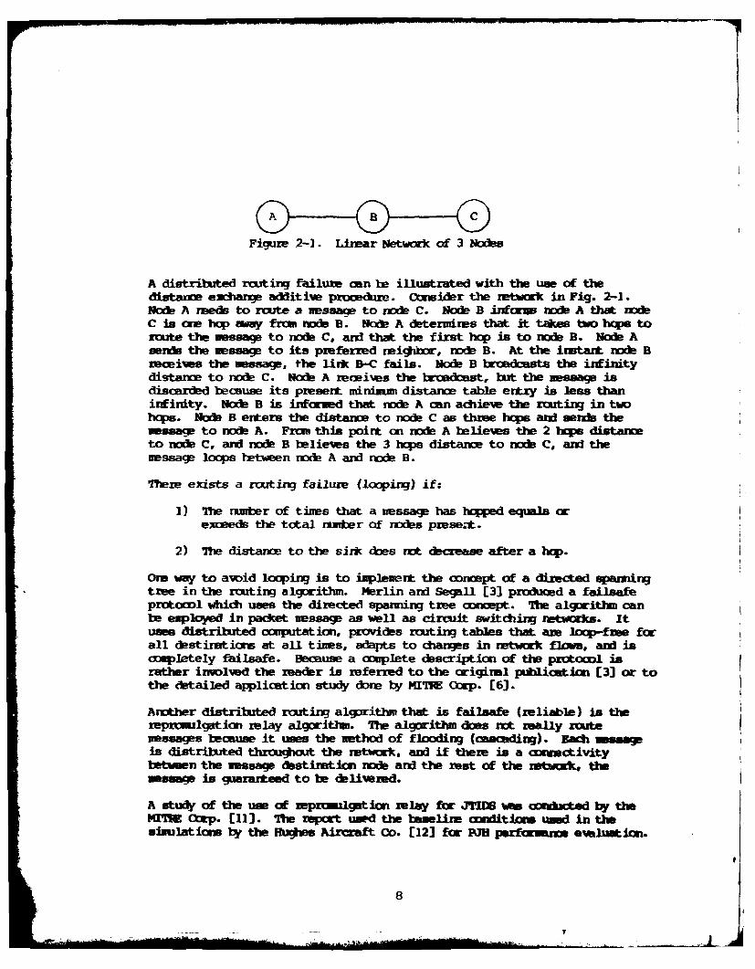
Figure 2-1. Linear Netwk of 3 Nodes
A distribued routing failure can be illustrated with the use of thedistance exhange additiw proced re. Consider the network in Fig. 2-1.Nae A nae to rcute a message to nod C. Node B infras rode A that wdC is one hop way fra node B. Node A d&terines that it takes f htops toroute the vessa to node C. and that the first hop is to noke B. Haft Asands the message to its preferred reighDbr, node B. At the instant node Breceiws the message, the link B-C fails. Nob B broadcsts the iifinitydistance to node C. Node A reCeives the bradkawt, but the message isdiscardAed because its present mininm= distaxc table entxy is less thaninfinity. Node B is informed that node A can achieve the rzouting in twohops. Node B enters the distan to C as three hcps and seib themssap to nods A. From this point on node A believes the 2 Ics distarto nodb C, and node B believes the 3 hops distaneu to node C, and themessage loops between node A and node B.
There exists a routing failure (looping) if:
1) The number of tines that a message has hoed eqals oexceeds the total number of nodes prese.-L.
2) The distance to the sink does not dLerase after a hop.
Ore way to avoid looping is to implement the concept of a directed spanningtree in the routing algorithm. Merlin and Segall [3) produced a failsafeprotocol which uses the directed spanning tree oncept. The algorithm canbe employed in packet message as well as circuit switching netwrks. Ituses distributed computation, provides routing tables that am loop-free forall destinations at all tines, adapts to changes inr nretrk flows, and iscompletely failsafe. Because a oplete description of the protooxl israther involvd the readr is referred to the original publication [3] or tothe detailed application study done by MITR Crp. [6].
Another distributed routing algorithm that is failsafe (reliable) is therepIgation relay algorithm. The algorithm des not really ouatemessas because it uses the method of flooding (cascading). Eadh assaeis distributed throughout the network, and if there is a onnectivitytmeen the mssage destimton node and the rest of the naboork, thewassu is guaramteed to be delired.
A study of the use of iopzlgtlcn relay for JYIDS wa M cted b themIUT (otp. [11]. The port usd the baeline onditin used in thesimulations by the Hues Aircaft Co. [12] fco rH puannm ewvluaton.
8

Tte raart projected that 152 'S/S (timeslots per second) in timaslotcapacity ae reedd to satisfy the total throu~pit requirement. Thise coui the 128 TS/S capacity available on one net.
An dwicus solution to the prdblem is to use more than one net to satisfythe total capacity requiremnt. Tw sdeme were proposed: divide thedivisional JTIDS participants into three functional ieprcoulgationcummuities, cc irto five geographic communities. The functinalcoumunities scheme has a serious shortcoming in that "local connectivity maycause a terminal or group of terminals to be isolated from its cmminityeven though the oerall connectivity for the area would seem to allow forfull local conrectivity" [11]. This leaves the geographic grouping sdinefor consideration.
In the geographic grouping scheme, the JTIW ommunities are carefuLlydefinad so that most caunicatiore are confired to within each cxaunity.Irtercoamunity "gateway" allocations db exist but are mininimed for bettertineslot rescurce utilization.
The repraulgation relay algorithm is reliable, but as reported, itnecessitates the use of several nets to satisfy the total capa Ityrequiremnt for a division-sized JTIDG uommunity. Ihat would be ideal is tohave a reliable routing algorithm that wuld allow for the possibility ofche use of a single ret to satisfy the total capacity requiremnt.
An investigation of an optimal approach for tiueslot allocation wascordocted [101. The paper indicates that there is the possibility of aconcurrert use of tineslots by the transmitters in the sane nt. Therepromulgation relay algorithm does not allow for the use of the optimalapproach for tislot allocation.
2.2 Mssage Volume
Ore of the inportart issues in distributed routing is mirniiing the controlmessages gererated for routing. A proliferation of control messages ritonly depletes the retwork capacity, but also creates umcessazy mssagetraffic congestion which may lead to a rettork failure.
Capitalizing on the hierarchical nature of tactical retwks which tend toconstrain needliras to local rets within a global netok, Bramble and Nayk[4] took a unique approach in developing a distrihuted routing algorithm. Alimited volume of coitrol messages is gaerated locally to communicate theconrectivity status infcrnution necessary to satisfy the medlimsassociated with each pair of message origination and destimation points.
9

The algrithl wks as follows: A xukb .4,j4- - a -it imurm). inits attempt. to locate its mssage detin mr, twais tos*). mx thnu*%its teridml omectivity matrix ("Or) tar ow oig* ?Wlmly, a "-. onlyimintains the connectivity quality () entries t t raimmnconts tha amwithin tw hops of the node holdi r the 1"). i t m urxw 4aks. not find.its sink, it sends its direct comminicams a Iie' I 4 auneivityirteYrogstion mussag. Upon receiving the iftAr imt m3 m , sadhdirect communicant seards thromph its TC2 for the ai*. Of ¢xrmw, it thesink is further than three hops from the source n direct commicnt wiltfind the sirn in its T04.
When the source does rt receive a xonnectivity status mmmsae within agiven period of time, it gemrates a level I comectivity ibterrogatimessag in an attempt to broaden the search radius to 4 hcps. fTe directoommunicarts of the source receive the level I iterrogatian message, andeach takes on the function of level 0 interrogat rs. The level 0irterrogat ions are then received by the direct Crm nits of the level 0irteric t , but are processed only by those who axe not alreadyparticipating in the seardh. Therefore, iziplicit in the algorithm is theuse of the udniiun spanning tree, with a flag of one kind or anotherindicating the rods telonging to a minimum spanning tree. If the simk islocated many hops away frou the source then seque r ed omrectivityirterrogatiw vessages of increasing levels are Ibroast by the scuzuntil the first connectivity status nessage is received.
The upper bound on the capacity oonsuned by the interrogation process insatisfying a medlirs is
TS(r) = 211+2+3+...+(r+])],
where r is the runber of relays in the route. Using the identity,
[the sum of i frm i=l to i=mn] = m(m+l)/2,
we can restate the above relationship as
TS(r) = (r+l)(r+2),
where we' substituted r+l for m.
When alternate routes are also osidered, the capacity oraxmed by theirterrogation process is less than or equal to s(r+l)(r+2). where s in themter of alternte routes required.
Gien n-50, 9=2, E[rJ=6, and E[XI/nJ=5, where n is the rujer of n ls dW/n is the nutber of rmedliras origirating from a node, 28, TS areax umd by the irterrogation process. Since them are 128 TS per aea -ud,we find that it takes 3.7 minutes or less to initialize the retwock.
IC

Tb cmrrectly estimate the initlizatian tine for a mtwx, the paranetersof the rmtwork must be orrectly assessed. Mcruillan Rider, and Rosendbeervd in their ARPANU study [5] that "although there am sites on theAMPAMT separated by as many as 11 hops, abxt am-third of the sssages inthe network travel no more than ane hop; about half travel no more thanthree h s. urthermore, a MITC working paper [6] projects the averagenuftr of hops per needline for a PJH network to be
Xhcps/NLI given 40 nodes/network = 2E~hops/NLJ given 250 nodes/rtwark = 3.
Fbr t works it is clear that the maber of hps expected to satisfy amedlim is rather small. Under this assunpticn the Brauble-Mayk algorithmshould perform wl. For the algorithm, global information sharing is notrequired, and the nitber of connectivity interrogations is minimized by thereception of regular broadcasts of (direct) aoumunicant status rrssaps.
2.3 Netwr !!L Tine
The response tine of a network is defined as the amount of ti-a required fornewok infarnmtion such as topological changs, rew reedlire requirements,routing, and the like to propagate through the retwork and read a rowsteady state.
Sane routing algorithms propagate update messages throumicut the rtwork%ben a tqpological chang ocrs. When an update ressage is propagted,transient loops may develop. An exaple of a routing algorithm that issusceptible to prolonged transient locps is the original routing algorithmfbr the ARPATEF. The algorithm uses the distance exdange additiveprocedure where distance information is not only shared node-to-node but ispi ssed by the receiving node before it is ready to broadcast the message.Although the algorithm has safeguards against permarent lps, transientloops were observed to exist for prolonged periods. Te new routingalgorithm for the AWRPANET [5] floods the netwok with update nessages whichtravel unrdagred to all nodes in the network. Information is sharedglotally ard rapidly, minimizing the durations of the transiert loops.
Tw awerage length of an update message is 176 bits for the maw routingalgarithm cxqxpred to 1200 bits for the original routing algorithm. Theupdte rate is less than two updates per second per link for the rew routingalgorithm ocxpared to the rates for the origiral routing algorithm which canbe a hiqh as seven updates per second per link. It takes on the order ofIS for all nodes to respond to a tcpological change using the row routing
alqirilu

Mcuil1an, Ridcer, and Rosen [5) attribute the shorter repmnse tim tousing local i:tation instead of the glotal coxptIo n used by thecrigiml routing algorithm for the AWMI r. Global cmcutation at anyinstart dpends wrae on the history of events around the zuwork than an thetraffic in the network at that tim. But for the local oomXpaticZ beauseinfcruntic distribution and irfczration prucessing are inependentprocesses, the traffic in the rnetk is wore accurately conxeyd to allnodes with muniniu delay. For these reasons local camputation is betterthan distributed global cipatxion.
12

3.9 IORSIC IOClTIM PMOXXI
he basic rating protocol (B4) works as folows: A umimm apanning treeis grown from a nessag crigiration pairt (source) until the messagedestiation point (sitk) is found. 7he path between the source and the sirkfaurA in the minimu aparming tee is the shortest path between the twopoits.
The protocol controls nessage delays by routing nssages throug the nodes 4that have the suallest operating capacities. Cgstion control and minizah1p path rcuting are ctained by using hop distanc (the anker of relaysrequired + 1) as the primxy ost and path capacity as the secondzy r twhere the path capacity is the sum of the capacities of the nodes used inraiting.
A graphics sinwintion program was developed. The program is used togenerate variaus node deploysnt cmfigrat im. Each ownfigumtIm ofnodes has a networ comectivity which is ra;xkmly earated. Userdeterined needlires ae established and distrihited routing of nessags isgraphicaly de-istrated.
3.1 Lirk ost
Mquillan, Richer, and Rmen [51 used the packet delay as the Urk cost forthe rew rcutin algorithm for the ARPANMr. Haewer, they report that "rhelew algriti tends to route traffic on minmuma hop paths, . . . e nuse their ornclusinm to use the hop as the Link o0st instead of using theactual delay neasurevents. But the uuinmkv q path xuting isn't alwys ancptbam routi*n beause it doesn't take into account itor Clcwriatimu in traffic ouhditiokx.
STe W e-O ctro uity raquirenmrts of the nodes to determme and reactto the traffic corttrx.. The capacity requirent of a node can be foundfrom the original transdt (Or) tineslat requireverts. (The e3peced mugo rof timeslots required during an epodi/cycle for a lire-of-eight reedliratramidssion is the OT tineslot requireuent.)
A rob camn serm as a vessag origination, destiration. or relay poet. orany combimtion of them. If a rnde serms only as a vessag crigimtinm ordestirtfo poit its capacity reruireat is the OT tmeslot requiemant..Te caracity reATureint of a relay is twice the Or tireslot requirenent.Siullarly. the e Daity requirerent of a xoe serving as a conbirntioa ofressace cfrirat in, Ae'-t itor, ane! relay poirt car be cxwpted.
Ar almrith, mn te irpleverted which rct crly seeks to fire! a ium-hqtTat% rru t,-, ut also to talance the ce"city load arrvng the r'-s in the

network. BW ummes the odninum-hqp distaxne detezudtatimxn first and theuurniuna-capecity dist: me~ dtermzrt ion semnd with each nd enmutemddk~riuvg the routing.
CQonider Fig. 3-1. "am iaok onnectivity is ilustrated in Fig. 3-1a.The c~pScfty mquimmrt ammoeated with each lirk In s ilustrated in Fig.3-lb. Three PcuSIhle pathe exist beten I~ A and J-x B as ifustratedin Fig. 3-1c.
RouteHcp Distance
1 32 33 4
Table 3-1. Hcys Requirad fo Eacb Route
Referring to Table 3-1 route 3 Is rejected because it does rot satisfy tievudmml-4Ep-path requirenert.
Rucate NO. WI* I Lirk 2 Lirk 3 717L
Table 3-2. Capacity DistAme Table
Althougfi the hcp distanoes for route I andl route 2 are equal, the aqxcitydIstalK~aS am different, as shon in Table 3-2. Muate I would be thmlogiCRl rcxutil dioice to satisfy the rxxU A - m 8 redlIm. (Ikte thatthe Wik maigbts mnet apacity zeuireumts (cots) and not apacityaimilability.)
The next omoion inmticot tw pruibIeu in czxwmctigm with gapfm: theminimi tCtaLI brch a t pvclem ancl the mixnu path -,stm pzcbem. fte
uin blm pIisI of partioilar irtemut because the pzc1m deals With?ftIdig tim path of mIdmu total length batwemn two given rclan.
14

I
a. Network Connectivity
b. Link Capacities
c. Available Paths
Figure 3-1. A Simple Routing Problem

3.2 rah L and Routing
In this section, a discussion of graph theory pre s the discussian Of thendnim total branc cost problem ard the injimim path oset prcblm. Ftr amore dtailed discussion of graph theory, the reader is referred to Gala r['3].
A graph is represented by G(V,E), where V is a set of wtices (nodes) and Zis a set of edges (lirks).
A tree is a graph with one and only one path between every two nodes. Agraph which has loops, or a graph which is cyclic, is not a tree. A tme isdefired as an acyclic on-ected graph.
A directed spanning tree is used to find a route betwen two givn ids. Adirected spanning tree has a rrx± whidh initiates the growth of the tree.(The BW assigns the message sourc as the rot of the tree). Starting firthe root, the tree grows urtil the sirk is foun] in the tree. A pathbeten the source and the sirk is effectively established if the sourc andthe sirk coexist within the tree.
E. W. Dijkstra [7] prorx d a rnte on two problems in onnwctim with graq*wtdch is of interest to our present discussion. We've explored the twoproblems with the use of a aumputer graphics simnlatimn. The resultsobtained are discussed in the next two sections.
16
: . . ... •- " . . .. ' - - " 7 --- " '"T i .. .. .--. .. ... .l -J

3.2 .1 .Kindm '[t., BMnclh CntMU
Consider a attuatJion in %,Adhd them am n n es0 ndh lidkd to at least ne&her node sudh that all moe a wwmwted. either directly or indim1ly.initially, all -oits m in th wit
aIrMm - [C (1). & 90 b. (n)].
and them is no nod in the - iM. "m fizot givan no& n(i) istransferrd fr the not C tO tet "M mUh that
I = - n~t)];
i) is nowthe rot of t ti . ?u mt of tr nofde from the metOUI am t awfenrd to the me TW In m.egm and in such a immerthat the nof fro the wit Q ot has the ihateat i1k to any of thends in the set M is trauuhmd fist. Vkh e t..-afer of a rxle,the lirk that w umd as the artot li* km a brandh of the tme.If all node am corected, either dimctly or indirely, the set TM willonsist of n ndes. ard the set (113 will be an epty set.
This algcrithm is desigrmd to generate a tree of uindxum total length amonn given nots. This algrithm is not of use to us im wuue it does ntpmviuxe a path of didum total length between the rot of the trme and anyother given nodb. The algirltlm lrever, is applicabe to problem likefinding the prcems for conmizig tersnrals with a ndmnm total cst.
A computer graphicu simulation pro am was used to ductzate the algorithmat work. Mhen compared to the simulation result fournd in Fig. 3-3, thesimulation result obtaired in Fig. 3-2 is clearly a tree of shrter totallength cooecting the given 30 "os.
I
II

UNIFORM DEPLOYMENT DISTRIBUTION - CONECTIVITY
lie
II
1-
UNIFOWI DEPLOYMNT DISTRIBUTION - SHORTEST DRANCi ALGO.
"4
'4 ,1 OOT
4 .¢
jt° ~ ~~~~. . ...... °. .- " ''
• *" -----i
4, ........ ..
Figure 3-2. Minimum Total Branch CostAlgorithm Graphics output
18
1I

3.2.2 Minim= Path Oost Protblem
Consider the save situation described in the miniuum total branch onstproblem. Initially, all nodes axe in the set
OUTSIDE = [node (1), node (2),..., node (n)],
and there is no node in the set T1PE. The first given node n(i) istransferred frozn the set OUTSIDE to the set TIM such that
T = [n(i)];
n(i) is now the root of the tree. The rest of the 1ods from the setOUTSIDE are transferred to the set TREE in sequerie and in sudh a namnerthat the node frum the set OUTSIDE that has the shortest distaw- along theexisting lirks to the root of the tree is transferrd first. (Distane isdefined as: lirk cost (source, relay 1) + lirk cost (relay 1, relay 2)+
+ lirk cost (relay m, sink).) With each transfer of a node, the lirkthat was used for shKrtest distane and which wasn't a barh of the treebecomes a branch of the tree. If all nodes are connected, either dixectlyor indirectly, the set TREE will consist of n nodes, and the ,t OUTSIEwill be an eupty set.
This algorithm is used to find the path of uinimum total length between twogivn nodes. Fbr this algorithm to produce the desired path, howewr,either of the two given nodes must be the rot of the sparming tree.
The graphics simulation output in Fig. 3-3 shows a spanning tree gereratedusing the shortest path algorithm. The total length between the rot andany other node is the minimm total length between the two nodes. Note thatalthocjh the miinimnn total length between the root and any other node isadhievd with the use of the shortest path algorithm, the total length ofall the lirks is greater for the tree in Fig. 3-3 when coupaed to the totallength of all the lirks for the tree in Fig. 3-2.
19

UNIFORM DEPLOYMENT DISTRIBUTION -CONNCTIVITY
UNIFORM DEPLO0YIEN DISTR!UTIJN - N -I PATH CO.
* .- 'ROOT
4-................4.. . . . . . . . ... . . . .
++
44
Figure 3-3. Minimum Path Cost AlgorithmGraphics Ouitput
20

3.3 cE Levels
When a path coet is defined in term of hops, each lik cost carries a valueOf unity. 7he distance between any tw given points is the nrntber of hcpsrequired to route a tessag from the origination point to the destinationpoint.
The hp level of a node irdicates fhe number of 1bs required for a messagfrm the source to reach the node. A minimm spanninig tree grows in such aManrer that the nodes belonging to the next hp level becue a part of the
uinimm spanning tree. Consider tht following scemrios.
Scmrnrio No. I. Level I Pnaaticm
branch 3 branch I
'-:(qur 3-4. level I Prcpagatici
Referring to Fig. 3-4. , Ios A, 8, and C belong to level 1. They aeraiadned to in noI seqence of A. B, an C, because the roe capacities are
Capacity oot (nole A) - ICapacity cot (rxi B) -2Capacity ct (rde C) 3Capacity os (source) - 1
Scenario No. 2. level 2 P'qpaqti
Figure 3-5. Level 2 P tion
21

Referrring to Fig. 3-5, the nodes that belong to levl 2 are node D and thesiuk. The node capacities are
Capacity cost (node D) = 1Capacity cost (sink) = I
The source, having cxuipeted the level 1 phase, requests nodes A, B, and Cto submit a branch of cpportunity. Node A has 3 links to choose from
Ct,(A, socte)wD(A,B)CD(A,D).
The lirks associated with CQ(A, source) and CO(A,B) axe rejected becauue thesource and node B belong to the set TREE = [source, A, B, C) indicated by aflag. Node D associated with the remaining link CQ(AD) is chosen as depreferred reihbbor of cqrtunity and the followirg assignments axe ndez
Hop distance (scurce, D) -> SHRT (node A)Capacity distance (source, D) - ISS (node A)
node D -) TER (node A)
Node A submits the three vriable assigrenlts to the sourc.
Next consider the equivalert processing at node B. Node B detects thepresence of the sirk, requests the sirk to submit data, and =ums thefolloing assignmerts.
Hop distance (source, sirk) -- SIVf (node B)Capacity distare (source, sirk) - LSS (node B)
sirk -, E'TER (node B3)
Node B submits the three vriable assigiments to the source.
Finally, coDnsider the equivalent processing unKlrtaken at node C. Node Cdetects the presence of the sirk, requests the sink to submit data, andmakes the following assignments:
Hop distance (source, sirk) -> s) (node C)Capacity distanu (source, sirk) -- ES (node C)
sirk - i (node C)
The source, therefore, receives the infcration submitted by ali peripheralnodes of the uinimm spanning tree (PtIST) and finds that a sink detectinhas occurred. The informtion submitted by od A is discarided kcauem theinfximtion does rot pertain to the detected sink. Hower, the source hastwo paths to the sirk to docoe frma, both of which are of the sam hcp
22i

distance. An cbicus dioeia would be the path that has the least ezpectedcongestion. Table 3-3 illustrates the capacities that are inolvd.
CRAM[1Y OM6lSRcute Source Relay Sink ITM
Source-B-Sirk 1 2 1 4Source-c-Sirk 1 3 1 5
Table 3-3. Capacity Distance Table
The source chooses the Source-B-Sirk path because the capacity cost of theSourm-B-Sirk path is less than the capacity cost of the Source-C-SinIk path.
Fig. 3-6 illustrates the decisim process occurring at the root of a uinimunsparning tree. Fig. 3-7 illustrates the decision process occurring at aperipheral rxe of a minimm spanning tree. The two processes arecoordirated for the growth of a vdnimm spanning tree.
23

-MEEMMM
A J*DAYLMSS
gg&rr&jkAAs
tj Do
Y&S LUST
M44AR&
ANA AO Cf
tA #AM A
A%
is
as so.
Figure 3-6. Decision Process at the Root
24

AIKifO.ty
Figure 3-7. Decision Process at a Peripheral Node
25

3.4 Pouting List
A routir list is a sequerxed list of the nodes xequixed to cratrut aroute frum the source to the destitution, starting with the souce teudmilI.D. No. and ending with the termiral I.D. No. of the destiation.
Figure 3-8. A 3-node Linear Netwok
A nmimn sparing tree with the soure as its rr-- seardm for the sinkthrmxb a growth process. At any tine prior to sirk dftm:tin it isessential for the source to keep a orplete kuwlege of the routingrequireverts of all PR6'Ps. Consier the retwork in Fig. 3-8.Node A is the source and r e C is the PN6T. The saicm Nay keep thefollowing routing lists:
List (A) = [A]List (B) = [A,BJList (C) - [AB,CJ
To reduce the memry requirevents of the souce, howemr, the smxrm keepsonly the ra*ing list of the PNMS. Consider the ratwk in Fig. 3-9.
Figur 3-9. A 7-,e Network
t* souroe keeps the followir rouing listaz
List (B) - [Scurce,A,]List (D) = [Source,C,D]List (F) = [Soure,E,F]
The source &ies ro keep list (C), List (A). and list (9).
iI......................................

I
3.5 Puting Failure
A loss of a route can oocur ven a loss of cwectivity is experieried. Arouting failure can be awided if a loss of route is detected and c€rzeddby having the sourae is nitiate the ruiting procedure. The key to detectionis the ruting list.
Figum 3-10. 4-nx Lizaar Network
Consider the netwrk in rig. 3-lj. Nade A bos a route to node D as foLloms:
A - B - C - D. Node A send its mssa with the routing list
List (D) = [A B,C,D].
Node B receivs the nsssage and sends it to C. Node C mxivw s the message,detezuiues that the rext node in sequenc is node D, bit firds that the lirkCQ(C,D) no longer exists. It retura a now rafting list of
List (A) = [C,B,A]
which has the revrse sequence of [A,B,C]. When rxd A receiws the messageit zeinitiates its routing procedure to fird an alternate path to node D.
3.6 Multiple Needlires from a CQmuon Sourc
It was previously stated that a routing procedure is initiated uponrealizing a redliw. This implies that a separate nxini spaming tree isinitiated for each reedlire. Hwever, a redction in the tine it takes toinitialize the retwar* can be adhieved when a oammn tree is used formedlims from a axmon source. Under this scheme, the mininm spanningtree pzcpagation is halted when the nzter of sinks that axe located isequel to the nmtner of reedlines criginating from the cmmon soure.
3.7 Sinultameus 0Crrenc of Minimf= Spamng Trees
As described previously, the variables used by the BRP are not capable ofhandling a simultam-cus ocrrenc of minimum spanning trees. There are twosolutions to the problem. each with its advntages.
27
- -'

Solution No. 1:
All variables will be modified to acommdte a mw array ax9ument thatidetifies the minimum spanning tree that each variable pertains to. Thismethod adhieves the capability far handling simultarecus oocurrenc ofmjninum spanning trees at a cost of an increased memory requirement of theterminal processors.
Soluti-,n No. 2:
No rodifition of the existing variables is required but the occzurrene ofthe minimw, spanning trees is sequentially crchestrated so that mo twominimmm spawir-gg trees intersect a rncde at awy given tine. This methodachieves a substartial reduction of the memory requirment of the procesersat a cost of taking loner to initialize the etwork.
3.8 BRP Simulation Results
A graphics sinulation program was developed to cbserv the state of aretwk as a function of tine. The program is capable of deploying up to30 rrs, using ary of the four rariJ- distributions:
I. uniform2. gaussian3. Poisson4. expne rt ial
Netwtrk conrectivity metrix can be randkmtly generated: each node-to-nodconnectivity quality (CO) is described by a 4-ary quality field gwrated byan expcrtial distribution rasn nuaber graort. The user controls thea~ezage degree per node so that a wide range of network ormctivities canbe generated.
Altho4f there can exist any number of reedlims in a retwk, a long anthe number does not exmed n(n-1), where n is the nuter of nodes in theretwork, for the purpose of cdtaining a clear visual understanding of thegraphics demonstrations w use a snall number of needlirms.
Fig. 3-11 shows the conectivity of a mtwk of 30 rarxmly deployed nodes.Figs. 3-12 and 3-13 show the reedlines used and the routes established tosatisfy the reedlines. W find that all paths am mininua-p paths.
28

UNIFORM DEPLOYMENT DISTRIUTIOJ - CECTIVITY
% .£-"
SJf
• jr
Figure 3-11. Network Connectivity
29
29

LIUMMFOt DEPLOYMMN DISTRIBUTION -XLIIS
+ +
++
+ +
+
+ +
++
+/ +
Figure 3-12. BRP Simulation Outputfor 6 Needlines
30
. . . .. . .

UN4IFORMI DEPLOYMENT DISTRIUTION -NEEDLINES
+ +
++
++
+
UNFR DELYETD +TO IIMIYPT
++4. ++
+
+ +
Fiue31.BPSiuainOtu
fo 3 +die
31.

4.0 EARLY r]EEECTIci KIPFU PF1TYL
The early dtect i routing prctocol (EIDRP) uses the BRP and the coxmumicaristatus (level 0) messages (C(S) to adieve distributed routing. Althcughthe BRP is sufficiert to route nessages, when CSMs are used ntxh of theinf rnation acquisition in distributed routing is adieved without the useof irnterrogat ions.
4.1 ommunicart Status (level 0) Messaee
A c xunicart status (level 0) nessage (CSMO) is a c)ntrol nessage which isperiodically broadcast by each terminal. It lists the connectivityqualities (Cs) of the broadcaster's direct crmiinicarts. A node thatreceives CSMs rot only krows the CQs of its direct camuunicazts, but italso knws the 012s of the direct cummunicats of its dirct ommicantsthrowch the use of its terminal connectivity matrix (TuM).
2 3
3 1
Figure 4-1. A 3-node Linear Network
Consider the retvrvk in Fig. 4-1. Nodes A, B, and C enter the net insequence. Upon entering the net eadi node regularly broadcasts and receivesa CSMU. With eadh reception of a CSI4 each node updates its terairalcorectivity matrix (t7) and its CSMO broadcasts. Table 4-I summarizes thecorplete update events of the CSMO broadcasts that occur.
Count Sender CQ(A,B) CD(B,A) CX(B,C) OD(C.B)
I A2 B 23 A 2 34 B 2 35 C 36 B 2 3 3 17 C 3 1
Table 4-1. Camuunicart Status (level 0) Message
K'

The CSNO that a node rece ies is used to update the rode T0M. With erxxghupdtes, the rxxe gains a conplete bidirectional CO knowledge of all linkswithin two hcps from the node.
4.2 lermirnl Coxiectivity Matrix
The connectivity data base of a terminal is a matrix referred to as theTerminal Connectivity Matrix (TICM) which is contaired in each T[ termiMl.(To be comrtistent with the rest of the text, it should be pointed out thatthe words 'terminal" and "node" are used irterchangably in this section.)The TOC is used to store infcrmation an any terminal's connectivity withother netted terminas. Since, in a non-line-of-sight environment, theonrectivity of a particular terminal to other terminals in the net isiIcvnplete, each terminal will have a TM whic is said to be local.
Using Fig. 4-2b as the reference we wake the following observations:
I) The matrix is symmetric in the serse that if CD(i, j) is a rnzeroentry then (D(j, i) is also a rvero ertry. The symmetry of thematrir allows us to analyze the data by locing only at the upperdiagonal matrix (UEM).
2) The entries of the first raw of UVM tell us that terminals 2, 3,and 4 are the direct cxxmmunicants of terminal I.
3) The entries of the second and fourth row of UDM tell us thatterminals 5, 6, and 7 are the indirect coxunicarts of terminal 1.To establish the terminal I - indirect crmmunicant oumunicatiowlinks, the followiing rcuting arrangements are recessary:
a. 1 -2-7b. 1 -4-5c. 1 -4-6
3$

3S *0
4 8
2
6 7
CIRCLES REPRESENT TERMINALS
LIN ES 2REPRESENT COfiMMUNICATIONLINKS BETWEEN TERMINALS
a. A Network of 10 Nodes
1 2 3 4 5 6 7 8 9 10
12 13 )4
2 CID CID21 __ 27
3 CO31 __
4 3 ___45 46
5 CIO

4.3 Early Detection
Early detection of the sir* occurs in two phases. A PWI wiil d&ect thesink in the following r nrer:
1) A P4T first detects the presence of the sink to hops away f theudnium spanning tree.2) The PWM later detects the presence of the sink one hop away from theminimu spanning tree.
4.3.1 First Level Early Detection (FUM)
When FUM occurs, the PNME;T that detects the sink chooses the sirk as itspreferred neighbor of opportunity, interrogates the sirk for its rodecapacity, and halts its information gathering process. The PFST submitsthe bra nd-of-aprx'rtunity data to the source.
The source, however, does not halt its information processir upon receivingthe data containing the sirk information, because there may be otherinxxing data also containing the sink information whicdh nay indicate abetter route to the sink. The source gathers all brardh-of-apportunity datasubidtted by each PNWr, rejects the branch-of-opportunity data ntontainino the sirk infccimtion (if a sink data exists within the set ofsubnitted data), and selects the best doice among the remaiing data. Thereader is referred to the NP flowcharts for details of the decisionsin olved in the algarith.
4.3.2 SeoWn Level Early Detection (SLED)
When FU occurs, the PN r that detects the sirk two hops away froi itselfchooses the direct comuricant which is a direct cumunicant of the sirk asits preferred mighbr of opportunity, but unlike in the previous case, theinforwation gatheri i process continues urtil either FLE) occurs or thelinks to be ncosidered have been depleted. The PMM.S requests the preferredneictior of cpprtunity for the roe capacity, and submits theIrarcb-of-opporturity data tc the source.
The source rwitherr the data submitted by each PIbT, rejects the branches ofqppertunity not iricated by 111 are selects the Lest dioce aong thereimin H f data.
It is rx-asilhe that FLED and SiL car sinultanneusly occur for a givensubivt recuest .1cle. rkwever, they-can also occur simultaneously duringte infervvt i'w 4utherinrj process of a PRMT. A PN4WT nay detect the sink

two hops away fram itself, but the inportane of the detection is onlysecond to the inpartance of FLED, therefore the S) algorithm existsseperate from the FLE) algrithm and takes second priority to the FIBal~iritlw.
4.3.3 Early Detection Algoritbr
Early detection can be achieved by rethodically searding throug theterminna connectivity natrices of each PNMST for the sizk entry. Forsivplicity, we will asstne that all lirks are undirected, kidh implies thatall TCYMs are syumetric in the sense that if there exist a cmer CQX(i, j)entry, then there exists a nonzero O( j, i) enLry regardless of the actual (ODvalues.
Referring to the TM of Fig. 4-2b which is the onnmectivty data be ofterutmial I (found in Fig. 4-2a), we will assume the following
]) All lirks are undirected.2) Ternmial I is the source.
If we defire an entry (X(i, j) as the connectivity quality of the lik i-j inthe direction going from i to j, then we can igmre the Ixr diagonaertries of the TOJ and work only with the upper diagonal matrix (UI)because the entries of the LDM represent the connectiv.'ties of the reversepaths.
Looking at the first raw entries, terminals 2, 3, and 4 are terminal l'sdirect oommunicants. If any of the teireimls is the sirk, then FIB) has
Loinrg at the entries of the second and fourth ras. terminrals 5, 6. and 7are the indirect co~unicants of terrtiral 1. If any of the terzuirls is thesirk, then SLED has ocmrred. For terminal 1, rxx 4. 4, or 2 is thepreferred reibor of opportunity if node 5, 6, or 7 is the sirk,respectiwly.
MI

4.4 M Simulation esults
A graphics ED W shoulation progam was de%!ed which has the same userite aton E -t as the B sixulatim prgrwa. The zar is mferred tothe appendix for a full dscription of the prograpL
Fig. 4-3 dums the CNmectivity of a 17x37 Mar tatan netok. Fig. 4-4s the edlims used and the routes established to satisfy the
rnedlires.
Fig. 4-5 svbwm the conmectvity of a network of 3 randoly deployed nodes.Figs. 4-6 and 4-7 cxi the reedlives used and the rzutes establised tosatisfy the reedlines.
As eipected all paths sown are miinlneiop and min -z M ity paths.Tds nears that it is possihle to muintain a unifom capacity distributedItn r that is cpable, of failsafe distributed routing.
37
~L

MANHATAN %SQ.ARE GP:,!: NETWORK, - CONNECTTVY
S . .. . I ip p- t
0 4
Figure 4-3. A Manhattan Network
I 38

+ - *+ + + 4. . . . .- . . .- . .-
-y-.~+ i * + + + + + + + +4. + .4 - + + 4 . + + + 4 + +
+ + * * -. + -+ j- + + - * 4+ A 4
t
4- +~ .- . . . . . .4-. . ..
4.\.~~ .- . .- .- . .* .- 4 + . + .4-+ + + + + - + + +- + + + + ,
+ + +
+ +
14 + + + \ + + + + 4+ + + +
4+ - + + . . + . .+
0 + + + + + + + +-"
+
+ 4. + 4- + + + + + + +
+ + + + 4 4 4+ 4. 4- 4 . "4 + +
+ + + + + 4 4 4 44 4 4 .
* + 4 + + + + 4 + + + 4++4
4- + 444. + +- 4+44
4 4 +4 4 4 - 4 4 4
Figure 4-4. -Grapicsotpt for a
Manhattan Netwrk
39

UM1~OQM DCOLDYNCUT 1410TgznUTIOM CC*AiNTIVITY
Fiqure 4-5. Netvxrk Connect iv ity
40)

UNIFORM DEPLOYMENT DISTRIBUTION - NEEDLINES
4t .I + $ + + ++
+ + ++K .. + + -:, . + + "+ + +.+l4++
+ -!+ + +- + +
+ 4 k+ + ++4.4
I.t + + + + + + + ++ + + ++
I + + . + + + 4
+ ~+*+ + + + 44I + + + + +
t +k + 4- .* + + ,
++ + + + .+ +
~UNIFORM DEPLOYMENT DISTRIBUTION - IIINII i HOP/CPACITY ATh+ + +
+ + :. + " +
J4+ + * +
+ - + . + + +S+ + + +
+ +. ++ + + + +1 +++ + +- + + . +
+ + + " + + + + + +l + +"+ + + + .+ +' . + +-H
+ + +. +
+ .. + +at + + + + + +
4 . 4- . . . + 4+ V
+ + +
++ ++
+4 + + ++ + + + +
* Figure 4-6. EDRP Graphics Output for a IRandomI Deployment of Nodes
41
+ +i

UNIFOW DEPLOYMENT DISTRIBUTION - NEEDLINES
+ + 4+1 ++ -- 4 + 4-+ 4-* + +
+4 + + + + +4 +4. + + + + + + j
++ + +-++ + 4*.++ +
+ + +- +4- + +
*+ +4- * + +. . + + + + ++ +_+ : . + + + ++ ++ ++ +
+. +
+-
i +4. + + :+ + + JN
+ +-0 + ~ . . ~+ +.~ . 4 +
. + _ ."-. T ,
+" + + +.+ + + +
+ ++ 4
+ + + +# + .*
+ + + + + +
+4 4. ++ +t
+ + + + + +
~%+ +
+ + + . + ++ + + + +-+ ++40
+ + v +++
+ +#
++ +
++ + ++ +++ + + + + mi
+ + + +- +
+442+- +
+ + + + + + ++
Figure~~~~~~~ 4-.ER-Gahc+utu o
Rado Dely+n o+ +ode
++--+

S.0 T w 1s;u
The grapics siaulation zesults show that the Me ad for W~n difeztrnwcks- 7be patbs that meze gererated to satisfyr tOw redlines tomonsistently ininimun-~ipp andi udiniinze-oaty paths.
An exciting avewe of q4pzmdi tomart adbIeving an q*jm tzzzesk±allocation in 7UL retwmxku exists as ind~icated by skiscim i Es]. t"iaprah unlike the cumdity fkm, arac that weeve taken. seeks toq±izdze the thrmcftput by looking at the individml traffic coalitwim fcweach tiuusInt. AD Part of Owr Cmg0Uq zessam w will -, ,i iir thisapproach. first locking at It from the thecketimil point of vise, andi thenamewuing its Iuplemntability baed upcua the Painwter contints' of atypical digital brcaiast nwmi.
CUErS~tly. the autiom axe involvd in an onigoing effort to &velc asimulaticn tool fcw the mauook wmgr of a battlefield data distributionsystem. The sizmlatk tool is ezwiskwwd to be capal of qtimum rcuting.c*4tli capacity distrition. aihpting to tqpological dianges, andi reacinto dhanges in the commumications rued. of the rat wslcrikers.
7heautor wcldlike to thamk mr. zli Goli~anu a colleague at FxztMammf, for h elpful suggestions duing the writing of this repcrt.
43

1. Joit Tact ical Irfmntiwn Distribution System (JTfLD) laruniM Guide(1sizion 4). We TAF WEt marq-wit. WCzk ing GrW, Septent-er 19I83.
2. Okipenter, R.W. A E"iw of 1kautIM~ Alqithm. fcxr DistribuztedDitlrefo kNbiw21ks, the MIM Corp., Mardb 1961.
3. Pbriln, P.M. and Segall, A., "A Failsafe Distributed Routingj Po~l",!M.Traxua&jcns on cofiratcmr, Vol. CtO4-27 * No. 9.. Setembr 1979.
4. Bramble, R. ard MWyk.c I., "tA N~ew Routing Algorithm for DistributedPrxessing in 7M~ JTI)6". US ArMy CZaw Pseardi and Develcpieit Technical
-. cw (urpiblished). Febnuaxy 1982.
5. Mcicuillan, J ., Ridber, I -, and Rcoen, E -C -, "The Now Routing M]garitmfcz- the AINANET", MW Tzansactions on Ccuminications, Vol. CCM-28, No. 5.May' 1960.
6. PJ31 Decentralized Netck Managet: FUy Distributed ThePM I Qip., UP03M79, April 1983.
7. Dilcatra, E.W. * "A Note on Two~ Problem in Conrexion with Grapbso,Vkuerisdae Matbeimtik, Voltme I, Fp. 269-271, 1959.
9. Siliaster, J. ancl K~einrirvdc L., "On the Cqkwmity of Nulti-hcp SlottedAUR Netoes with F~qalar Structure". I Tranrsactions an ConzanicatacmsVol. CW~-3, go. 8, Augnit 1983.
10. SkIdsdz. C., -An Optival Apprcadi for Timssit Allocat ion in TCM~L ~Kwet", 2ndl Annimi. IM (kaferenae on Military Couunicationw, Odckr1983.
11. Jabldcov. A. ancl Rice, W., The Use of n-.pzunulat ion He1ay fcr JXIDS,The MIT b rp. r76 Nownbuer 1982.
12_7=/JI6 fi1yrlid DefinItion and Ewaluation Firal Acrt, EHuEwsAircrafrt Co., Septemter 198C.
13. Gaflager, R .G.. Data Qccmanication Networks, urgubliabed.
44

APPENDIX
aW raphcs Simulation
An HDR graphics simlation program was developed at the CIMI SystemSiulations Facility using the ReGIS Graphis LiWkraxy. The VAX KLRMIprrxwam runs on a VAX 11/781 computer with the VT125 terminal used for userinteract ion.
The program is divided into several segments: deployment of the nodes,generation of the networ connectivity, generation of a set of desiredreedlines, and roting execution. The routing scanario can be printed outon a graphcs printer along with the deployment, conrectivity, and needlinescevarics.
In the deploymnt segment of the program, the user dcomm a unaicmgaussian, Poisson, cc exponntial node deploynent Fotrib±.i . lr a userinterested in a theoretical research in network niagament them isavailable a MaIattan network option which prouacs an nm grid twrk,wbere n is an integer specified by the user. The number of nodes in thenetwor ranges from I to 300.
In the mtwork conrectivity segment, the pzrogram generates a rancbm neworkots tivity using the exnential distribution functin nuamter geuratar.(The expoetial distribuion function has a parameter Lrada whichdetermines the spread of the connectivity likelihood region.) The userspecifies the expected degree of a node. The user can produce aconnectivity rich retwork by specifying a large expected degree value, or aconnectivity poor network (or even a disconected retwork) by specifying awmll expected degree value.
In the reedlines segment, the program generates a random pattern ofreedlines usirg the unifccr distribuion function nimber generator. Theuser specifies the mzter of nedlines to be used, but the progrm doem ntgenerate more than n(n-1) reedlines, where n is the nmber of nosdeployed. It is also possible to generate reedlines with the use of agraphics cursor. The user controls te curscr oveint with the use of thearrow keys on the keyboard.
There is a segrert that graphically denoutrutes the shiatst-path algorithmwhich produes a minim-spanming tree rooted at a nade which the userspecifies. Fbr clarity in analyzing the results, the pski distanas thatseperates each pair of nodes is taken as the link cost. The results of anexecution of the algorithm are strongly influend by the retwcrkcomectivity that is used, 'so the segment can be a valuable tool for a userwho is interested in invstigating the effects of differing ntwkconnectivity on network usnagment.
45
-

FPimlny, there is a segment wtich graphially demratzates the distrilutedlrting of nessages using the E1 . There is n irut parameter that theumer iek to specify. The parameters that are used am the depIoyit,,oimectivity, ard redline data that were previcusly generated aid stmced in
fte autis am in. the p'cess of upgrading the EW graphics sioilatiuThm program listing is zot available fcx distributiu at this
time.
46
r4

I
LIS OF A(CWAG
EP bsic routing protocol
CD conmect ivity quality
CSW commrdicart status message (level 0)
H2W early dtecticn routing protocol
1 first level early detection
JTIDS Joint Tactical I DS,'1lion System
IM lower diagml matrix
or original truauit
Pin PIIG/JTIDS Hybrid
RRr peripberal node of the minimn sparmng tree
SK secxd level early dtection
TCV. teramitl comctivity matrix
TU9 tins division multiple acss
TS/S tineslots per second
UDM upper diagonal matrix
47
0l l I. . . . -. . . . . ." . . . . I l ' -
. . :. . .". . .. L '

-i I


