IEEE Transactions on Nuclear Science, Vol. NS-28, No. 2, April 1981PROTON BEAMS FOR IMAGING APPLICATIONS*
S. L. KramerArgonne National Laboratory
Argonne, Illinois 60439
Introduction
The idea of using protons for imaging purposes wassuggested more than a decade ago.1 Since that time,several attempts to demonstrate the usefulness of thistechnique for medical imaging have been made.2'3 How-ever, only recently have detailed analyses of the phys-ical advantages between proton and x-ray imaging beenmade.4%5P6 These studies show an expected dose reduc-tion of about a factor of 10 for proton compared tox-ray imaging. All of these studies assume that bothproton and x-ray systems are working at the quantumstatistical limit of sensitivity. However, the com-plexity of the bremsstrahlung beam, rapid variation ofabsorptive coefficient with energy, and complexity ofmaking high spatial accuracy and high detection effi-ciency detectors could seriously limit the practicalsensitivity with x-ray imaging.
Despite the theoretical and practical advantagesof proton imaging, very little funding is being pro-vided to pursue the research necessary to develop aclinical proton radiographic system. One reason forthe lack of this research is the cost involved in pro-viding a source of 200 to 250 MeV particles. However,the analyses of the cost of a proton accelerator havebeen based on the production of one-of-a-kind nuclearresearch accelerators, which are capable of providingbeam intensity and duty cycle considerably beyond thatrequired for proton radiography.
Figure 1 shows a schematic diagram of a 200-MeVproton synchrotron designed by several physicists7 atArgonne National Laboratory, to meet the requirementsof a diagnostic accelerator. It is capable of pro-viding a high quality, small energy-spread beam ofseveral times 108 protons per one second pulse at a0.3 Hz rate to one of several radiographic units. Thelow power magnets, low beam intensity, and low dutycycle of this accelerator could provide a cost reduc-tion of a factor of 10 or more over conventional
accelerators in this energy range. With this demonstra-tion that the cost of a proton source need not be pro-hibitive, a program was begun to further demonstrate theadvantages of proton radiography for medical imaging.5
Basis of Charged Particle Radiography
The basis for the interest in charged particles canmost easily be demonstrated by the transmission curvesin Fig. 2. The sharp decrease in the proton transmissionmeans that few protons will be required to detect smallchanges of the total mass penetrated by the beam. Forx-rays, the transmission will have to be measured ex-tremely accurately to provide the sensitivity to dis-criminate between the same small mass changes. Sincethe uncertainty on the transmission varies inversely asthe square root of the incident beam flux or dose, thegreatly reduced proton flux will overcome the increaseddose per particle for protons (200 MeV) compared tox-rays (60 - 100 keV).
The transmission curve for charged particles is theresult of a well-defined range (R in gm/cm2) in matter.The range depends largely on the electron density of thematerial and is quite insensitive to chemical composi-tion (except for hydrogen). The distribution of rangefor individual protons is approximately Gaussian with aroot-mean-squared (rms) spread about R, given by thestraggling parameter (a). For protons with energyaround 200 MeV and for biological materials,8 Cp=0.OllR.In a radiographic system, the particles will stop in arange detector and the deeper the penetration, the lessmass (X, in gm/cm2) the particles penetrated in passingthrough the object. The uncertainty in the mass pene-trated is just the accuracy that the average range canbe measured
6X = P' 0. 011R//ZY gm/cmP ,N (1)
where N is the number of particles detected. Since weare interested in comparing the mass resolution that canbe obtained for a given dose, it is useful to considerthe figure of merit for a radiographicprocedure givenby:
6X VDP = F(X,E ...)p p
(2)
where Dp is the peak radiation dose to the object. Thepfunction F depends on the type of procedure, the energyof the beam, and the object being radiographed but notexplicitly on the dose or mass resolution possible.
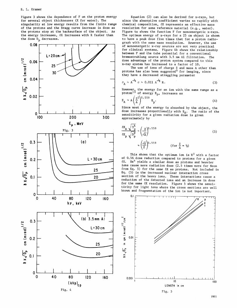
Figure 3 shows the dependence of F on the proton energyfor several object thicknesses (X for water). Thesingularity at low energy results from the finite rangeof the protons and the Bragg curve increase in dose asthe protons stop at the backsurface of the object. Asthe energy increases, 6X increases with R faster thanthe dose Dp decreases.
0.081 1 1 1 11 1 1 Z I
200 3 00
Ep, MeV
Fig. 3
0 40 80h v, keV
0 40
Equation (2) can also be derived for x-rays, butsince the absorptive coefficient varies so rapidly withchemical composition, 6X represents an effective massresolution for some reference material (e.g., water).Figure 4a shows the function F for monoenergetic x-rays.The optimum energy of x-rays for a 25 cm object is shownto have a peak dose five times that for a proton radio-graph with the sane mass resolution. However, the useof monoenergetic x-ray sources are not very practicalfor clinical systems. Figure 4b shows the relationshipbetween F and the tube potential for a conventionalbremsstrahlung source with 3.5 mm Al filtration. Thedose advantage of the proton system compared to thisx-ray system has increased to a factor of 10.
The use of ions of charge Z and mass A other thanprotons has also been suggested9 for imaging, sincethey have a decreased straggling parameter
aA A½ a- 0.011 AA R . (3)
However, the energy for an ion with the same range as aproton10 of energy Ep, increases as
z2 0. 558EA A- ) HE (4)A A ~~~pSince most of the energy is absorbed by the object, thedose increases proportionally with EA. The ratio of thesensitivity for a given radiation dose is givenapproximately by
XA P z 0.558
p p
z(for = ½-)
This shows that the optimum ion is H3 with a factorof 0.56 dose reduction compared to protons for a givenSX. He4 yields a similar dose as protons and heavierions cause more radiation dose (2.5 times more for Neonfrom Eq. 5) for the same 6X as protons. Not included inEq. (5) is the increased nuclear interaction crosssection of the heavy ions. These interactions cause areduction of the detected ions and an increase in dosefor the same 5X resolution. Figure 5 shows the sensi-tivity for light ions where the cross sections are wellknown and fragmentation of the ion is not important.
0.1120 160
cliEu1-
cli
.o0
E
EC7.
E
mnIF>x00
80 120 160( kVP)cp
Fig. 4
0.01
IT I T
/X/,Z 't
II1n
0.00 1 I I,to 0oo
LENGTH in cm
Fig. 5
1911
(5)
S. L. Kramer
c,sJ
20a
0.06
0.04
100
x 0.02
0
N, 0.3--a
a
20.
0.1xdo
0
SLi
0.3
0.2
clJ
las
u
0.1x
00-
I 1 I I 1 I(b) 3.5mm Al
30cm
25
20
I . II 1 I 1. , I I
t
S. L. Kramer
The reduced sensitivity of the heavy ions for a givendose, together with the increased cost of these accel-erators, makes these ions appear less useful.
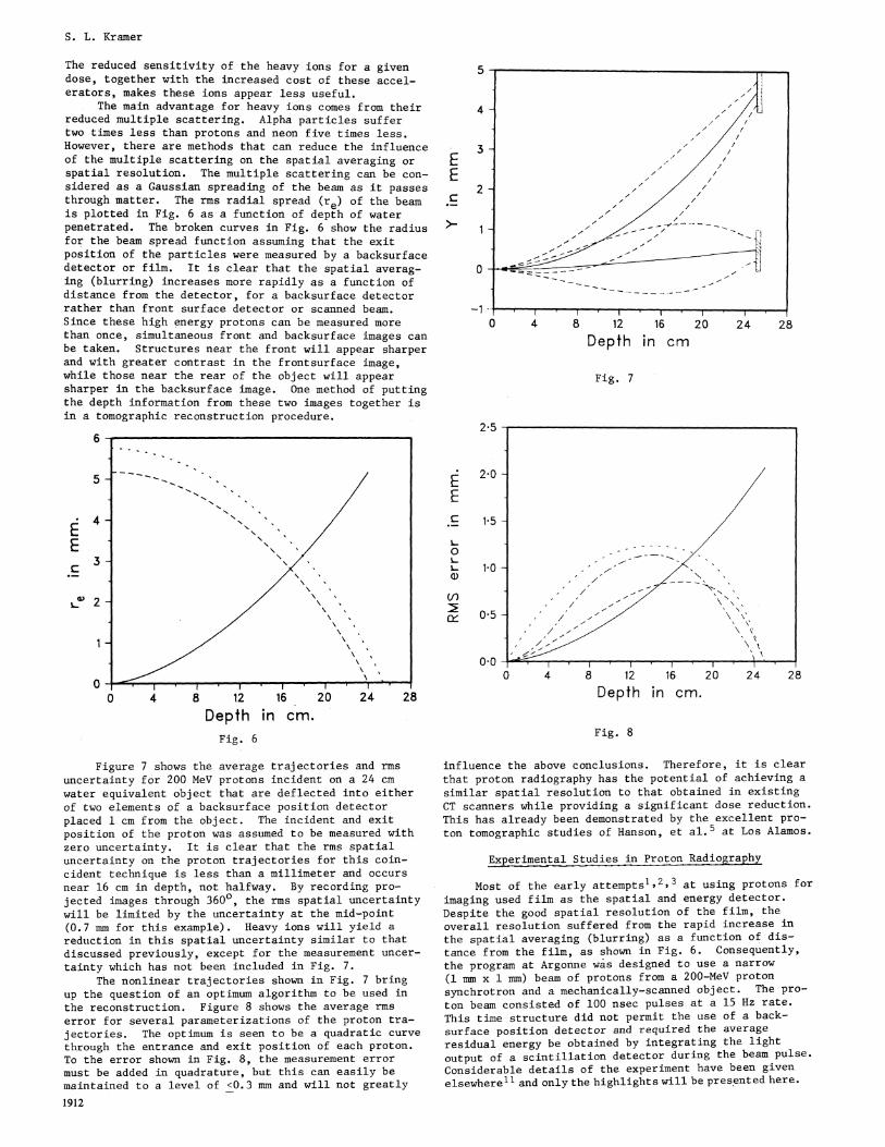
The main advantage for heavy ions comes from theirreduced multiple scattering. Alpha particles suffertwo times less than protons and neon five times less.However, there are methods that can reduce the influenceof the multiple scattering on the spatial averaging orspatial resolution. The multiple scattering can be con-sidered as a Gaussian spreading of the beam as it passesthrough matter. The rms radial spread (re) of the beamis plotted in Fig. 6 as a function of depth of waterpenetrated. The broken curves in Fig. 6 show the radiusfor the beam spread function assuming that the exitposition of the particles were measured by a backsurfacedetector or film. It is clear that the spatial averag-ing (blurring) increases more rapidly as a function ofdistance from the detector, for a backsurface detectorrather than front surface detector or scanned beam.Since these high energy protons can be measured morethan once, simultaneous front and backsurface images canbe taken. Structures near the front will appear sharperand with greater contrast in the frontsurface image,while those near the rear of the object will appearsharper in the backsurface image. One method of puttingthe depth information from these two images together isin a tomographic reconstruction procedure.
6
4
/\\''
E~~~~~~~~~~~~~~~3~~~~~~~~~~~~~c~~~~~~~~~~~~~~~~
L2
00 4 8 12 16 20 24 28
Depth in cm.Fig. 6
Figure 7 shows the average trajectories and rmsuncertainty for 200 MeV protons incident on a 24 cmwater equivalent object that are deflected into eitherof two elements of a backsurface position detectorplaced 1 cm from the object. The incident and exitposition of the proton was assumed to be measured withzero uncertainty. It is clear that the rms spatialuncertainty on the proton trajectories for this coin-cident technique is less than a millimeter and occursnear 16 cm in depth, not halfway. By recording pro-jected images through 3600, the rms spatial uncertaintywill be limited by the uncertainty at the mid-point(0.7 mm for this example). Heavy ions will yield areduction in this spatial uncertainty similar to thatdiscussed previously, except for the measurement uncer-tainty which has not been included in Fig. 7.
The nonlinear trajectories shown in Fig. 7 bringup the question of an optimum algorithm to be used inthe reconstruction. Figure 8 shows the average rmserror for several parameterizations of the proton tra-jectories. The optimum is seen to be a quadratic curve
through the entrance and exit position of each proton.To the error shown in Fig. 8, the measurement errormust be added in quadrature, but this can easily bemaintained to a level of <0.3 mm and will not greatly
EEc
12 16
Depth in cm
Fig. 7
2-5
o:EL.
V)
Cr)
2 0 -
1 5 -
1 0 -
05 -
0 0
4 8 12 16 20 24
Depth in cm.
28
Fig. 8
influence the above conclusions. Therefore, it is clearthat proton radiography has the potential of achieving a
similar spatial resolution to that obtained in existingCT scanners while providing a significant dose reduction.This has already been demonstrated by the excellent pro-ton tomographic studies of Hanson, et al.5 at Los Alamos.
Experimental Studies in Proton Radiography
Most of the early attempts12,3 at using protons forimaging used film as the spatial and energy detector.Despite the good spatial resolution of the film, theoverall resolution suffered from the rapid increase inthe spatial averaging (blurring) as a function of dis-tance from the film, as shown in Fig. 6. Consequently,the program at Argonne was designed to use a narrow
(1 mm x 1 mm) beam of protons from a 200-MeV protonsynchrotron and a mechanically-scanned object. The pro-ton beam consisted of 100 nsec pulses at a 15 Hz rate.
This time structure did not permit the use of a back-surface position detector and required the averageresidual energy be obtained by integrating the lightoutput of a scintillation detector during the beam pulse.Considerable details of the experiment have been givenelsewherel 1 and only the highlights will be presented here.
1912
---
,I/ I
I Is \/
7~~~~~~~~~~~~~~~~~~~~~~~~~~~~~~~~~~~~~~~~~~
I
f i I
S. L. Kramer
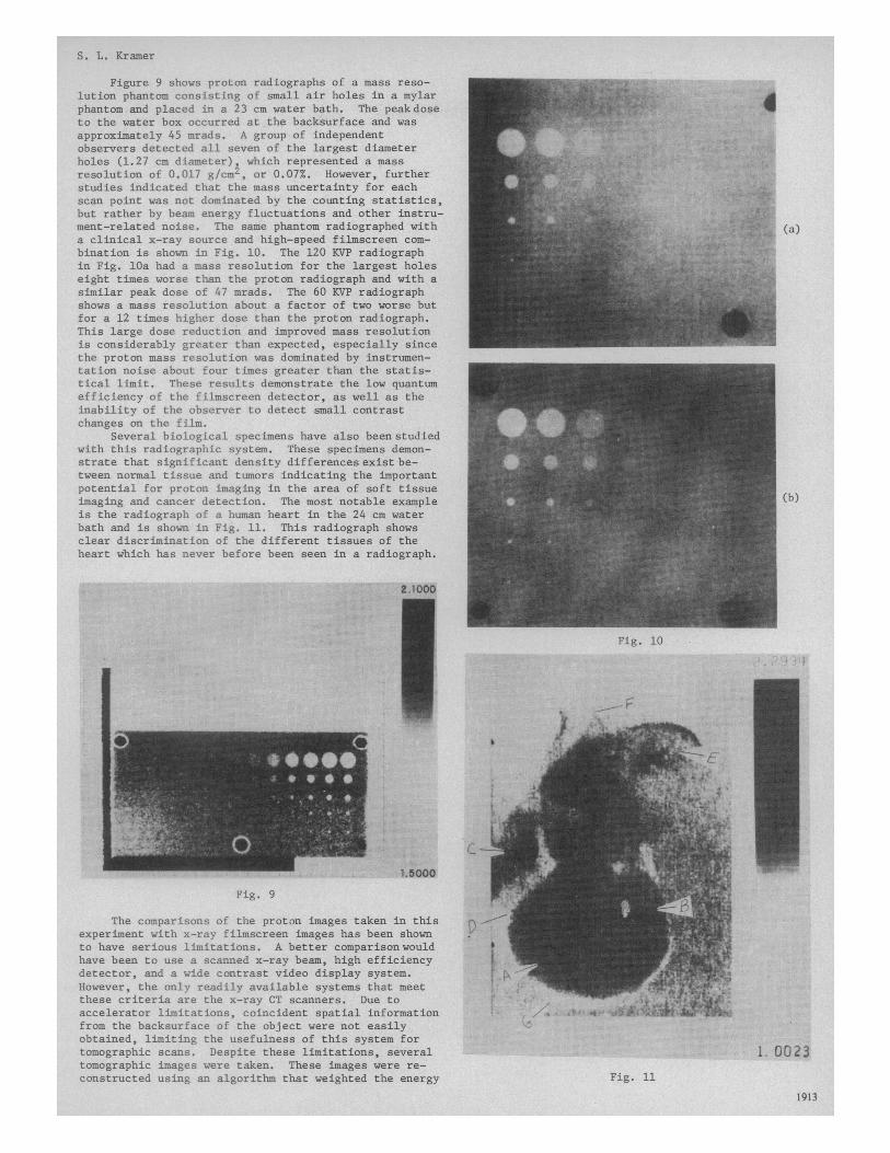
Figure 9 shows proton radiographs of a mass reso-lution phantom consisting of small air holes in a mylarphantom and placed in a 23 cm water bath. The peak doseto the water box occurred at the backsurface and wasapproximately 45 mrads. A group of independentobservers detected all seven of the largest diameterholes (1.27 cm diameter), which represented a massresolution of 0.017 g/cm2, or 0.07%. However, furtherstudies indicated that the mass uncertainty for eachscan point was not dominated by the counting statistics,but rather by beam energy fluctuations and other instru-ment-related noise. The same phantom radiographed with (a)a clinical x-ray source and high-speed filmscreen com-bination is shown in Fig. 10. The 120 KVP radiographin Fig. 10a had a mass resolution for the largest holeseight times worse than the proton radiograph and with asimilar peak dose of 47 mrads. The 60 KVP radiographshows a mass resolution about a factor of two worse butfor a 12 times higher dose than the proton radiograph.This large dose reduction and improved mass resolutionis considerably greater than expected, especially sincethe proton mass resolution was dominated by instrumen-tation noise about four times greater than the statis-tical limit. These results demonstrate the low quantumefficiency of the filmscreen detector, as well as theinability of the observer to detect small contrastchanges on the film.
Several biological specimens have also been studiedwith this radiographic system. These specimens demon-strate that significant density differences exist be-tween normal tissue and tumors indicating the importantpotential for proton imaging in the area of soft tissueimaging and cancer detection. The most notable example (b)is the radiograph of a human heart in the 24 cm waterbath and is shown in Fig. 11. This radiograph showsclear discrimination of the different tissues of theheart which has never before been seen in a radiograph.
Fig. 10
Fig. 9
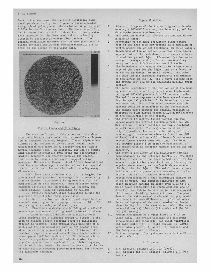
The comparisons of the proton images taken in thisexperiment with x-ray filmscreen images has been shownto have serious limitations. A better comparisonwouldhave been to use a scanned x-ray beam, high efficiencydetector, and a wide contrast video display system.However, the only readily available systems that meetthese criteria are the x-ray CT scanners. Due toaccelerator limitations, coincident spatial informationfrom the backsurface of the object were not easilyobtained, limiting the usefulness of this system fortomographic scans. Despite these limitations, several 1. 0023tomographic images were taken. These images were re-constructed using an algorithm that weighted the energy Fig. 11
1913
S. L. Kramer
loss of the beam over the multiple scattering beamenvelope shown in Fig. 6. Figure 12 shows a protontomograph of polystyrene rods (relative stopping power1.023) in the 24 cm water bath. The mass uncertaintyin the water bath was ±1% or about four times greaterthan expected for the dose used and was primarilylimited by accelerator energy fluctuations. Thespatial resolution measured for the same phantom withhigher contrast lucite rods was approximately 1.8 mm(rms) at the center of the water bath.
Fig. 12
Future Plans and Directions
The work performed in this experiment has shownthat considerable dose reduction is possible with pro-ton as compared to x-ray imaging. The multiple scat-tering of the protons which was once thought to beunacceptable was shown to be greatly reduced with anarrow scanning beam. In addition, the use of coinci-dent scatter information from front and backsurfacespatial detectors can recover much of the spatialresolution by using a tomographic reconstructionprocess. The work of Hanson, et al.15 has demonstratedthat the dose advantage is maintained and that spatialresolution is near that obtained with existing x-rayCT scanners.
With these demonstrations that proton imaging hasa very real and practical advantage, it is surprisingthat no funding is presently being provided for thecontinuation of this research. This situation makesplanning difficult and uncertain. At Argonne, thefuture research could be summarized as follows:
1. Develop reconstruction algorithms to use thequadratic trajectories shown previously;
2. Develop a low cost detector and magnetically-scanned beam to provide tomographic scans in 10 to 30sec, using an existing accelerator; and
3. Finalize the design and building of a 200-MeVproton accelerator and rotating beamline for clinical use.
In order to better define the signal-to-noiselevel required for a clinical proton CT system, a pro-gram to measure proton stopping power of biologicaltissues is planned. This program will make use of ahigh quality, low operating cost 50-MeV proton beam.After penetrating approximately 1 cm of tissue, theresidual range of the protons will be detected with axenon gas scintillation detector. The data obtainedfrom this experiment will not only determine thesignal-to-noise level required for a clinical system,but it will also answer the question concerning the useof quantitative stopping power measurement for diagnos-ing different diseases.
Figure Captions
1. Schematic diagram of the Proton Diagnostic Accel-erator, a 200-MeV low cost, low intensity, and lowduty cycle proton synchrotron.
2. Transmission curves for 200-MeV protons and 60-keVx-rays in water.
3. Dependence of the mass resolution times squareroot of the peak dose for protons as a function ofproton energy and object thickness (in cm of water).
4. Dependence of the effective mass resolution timessquare root of the peak dose for x-rays as a func-tion of energy and object thickness; (a) for mono-energetic x-rays; and (b) for a bremsstrahlungx-ray source with 3.5 mm aluminum filtration.
5. The dependence of the mass resolution times squareroot of the dose for the light ions as a functionof object thickness (in cm of water). The valuefor each ion and thickness represents the minimumof the curves in Fig. 3. The a curve differs fromthe proton only due to the increased nuclear crosssection.
6. The depth dependence of the rms radius of the beamspread function resulting from the multiple scat-tering of 200-MeV protons in a 24 cm water bath.The solid curve represents the beam spread assum-ing the spatial position of the incoming protonsare measured. The broken curve assumes that thespatial position is measured at the backsurface.The dashed curve assumes the spatial position ismeasured by film placed behind a 1.4 g/cm2 absorberat the backsurface of the object.
7. The average trajectory (solid curves) and rmsspread about the average (broken curves) for 200-MeV protons of known position and angle incidenton a 24 cm object. The trajectories shown areonly for protons that were deflected by multiplescattering into detector elements 0 to 1 mm (20%of beam) and 4 to 5 mm (11% of beam) from the ex-pected (unscattered) beam position. The detectorwas assumed placed 1 cm from the backsurface ofthe object with no absorber between the object anddetector.
8. The average rms error on the trajectory for pro-tons measured by the detector in Fig. 7. The shortdashed, broken curve and long dashed curve are forassumed trajectories given by linear, linear plusangular measurement, and quadratic dependence onthe depth in the object. The solid curve is one-half the total projected error assuming no back-surface spatial information is available.
9. Proton radiograph of a mass resolution phantom in24 cm of water. The phantom consisted of airholes in mylar ranging in depth from 0.13 to 8.1mm in seven steps with the depth doubling and indiameter from 0.8 mm to 12.7 mm in five steps, withthe diameter doubling from row to row. The peakdose to the water was 45 mrads and the gray scalerepresents the mass difference in g/cm2 of water.
10. X-ray radiographs of the mass resolution phantomshown in Fig. 9 in the same water bath. The tubepotential was (a) 120 KVP (47 mradsj and (b) 60KVP (561 mrads).
11. Proton radiograph of a human heart in a 24 cmwater bath. The arrows indicate the differenttissue which are observed: (A) right ventricle;(B) left ventricle; (C) right atrium; (D) atrio-ventricular groove; (E) aorta; (F) trachea; and(G) fatty myrocardial tissue.
12. Proton tomograph of polystyrene rods in the 24 cmwater bath.
6. S.L. Kramer, et al., submitted to Medical Physics(1979).
7. R.L. Martin, et al., IEEE Trans. Nucl. Sci. NS-22,1802 (1975); Proc. of IVth All Union Nat'l. Conf.on Particle Accelerators, Moscow, USSR, 370 (1975).
8. R.M. Sternheimer, Phys. Rev. 117, 485 (1960).9. E.V. Benton, et al., Science 182, 474 (1973).10. This result is based on the empirical range-energy
relationship for protons in water Ep = K R0558.This relation describes data and theoretical cal-culations quite well.
11. S.L. Kramer, et al., Radiology 135, 485 (1980).