ProtoTRAK Edge Programming & Operating Manual Southwestern Industries, Inc. 2615 Homestead Place Rancho Dominguez, CA 90224-9066 USA T | 310.608.4422 | F | 310. 764.2668 Service Department: 800.367.3165 e-mail: [email protected]| [email protected]| web: southwesternindustries.com Document: P/N 22061 Version: 062503
Transcript
ProtoTRAK Edge Programming & Operating Manual
Southwestern Industries, Inc. 2615 Homestead Place Rancho Dominguez, CA 90224-9066 USA T | 310.608.4422 || F | 310. 764.2668 Service Department: 800.367.3165 e-mail: [email protected] | [email protected] | web: southwesternindustries.com
Document: P/N 22061 Version: 062503
| i
_________________________________________________________________ Southwestern Industries, Inc.
ProtoTRAK Edge Programming & Operating Manual
______________________ TABLE OF CONTENTS Section 1.0 Introduction 1.1 Modes 1 1.2 LCD Screen 1 1.3 Turning on the ProtoTRAK Edge 2
Section 2.0 Description 2.1 Display Pendant Front 3 2.2 Pendant Back Panel 3 2.3 The Floppy Drive 4 2.4 The Tilt Adjustment 4 2.5 Servo Motors/Amplifiers 4 2.6 Remote Stop Go Switch (optional) 4 2.7 The Z Scale (optional) 4 2.8 Limit Switches (optional) 4
Section 4.0 Using the ProtoTRAK Edge as a DRO 4.1 Enter DRO Mode 9 4.2 DRO Functions 9 4.3 Jog 10 4.4 Return to Absolute Zero 10
Section 5.0 Using Teach 5.1 Making a Teach Program 11 5.2 Running a Teach Program 12 5.3 Erasing a Teach Program 12
Section 6.0 Programming 6.1 Enter Program Mode & Assign a Part Number 13 6.2 Programming Strategy and Procedures 13 6.3 Programmed Events 14 6.3.1 Posn Drill 14 6.3.2 Mill Event 14 6.3.3 Arc Event 15 6.3.4 Pocket/Frame Event 15 6.3.5 Repeat Event 15 6.4 Prompts Used to Define the Events 15 6.5 Continue 17 6.6 Assumed Tool Offset, Feedrate and Tool # 17
ii |
_________________________________________________________________ Southwestern Industries, Inc.
ProtoTRAK Edge Programming & Operating Manual
Section 6.0 Programming (continued) 6.7 Incremental Reference Position 17 6.8 Finish Cuts 18 6.9 Look 18 6.10 A Sample Program 18
Section 7.0 Changing or Correcting Programs 7.1 Aborting a Partially Programmed Event 21 7.2 Editing Data While Programming an Event 21 7.3 Editing Previously Programmed Events 21 7.4 Changing the Feedrate 22 7.5 Changing a Part Number (making a copy of a program) 22 7.6 Saving Changes to a Program 22 7.7 Erasing an Entire Program 22
Section 8.0 Making Parts with the CNC 8.1 Setting Up 23 8.2 Starting 23 8.3 Display Messages in Program Run 23 8.4 Program Run Prompts 24 8.5 Stop 24 8.6 Feedrate Override 24 8.7 Trial Run 24 8.8 Data Errors 24 8.9 Fault Messages 24 Section 9.0 Math Help 9.1 Procedure 25 9.2 Math Help Types 26
Section 10.0 Program Memory & Storage 10.1 Cautions About Storing and Retrieving Programs 28 10.2 Program Formats and Labeling 28 10.3 Enter Program In/Out Mode 29 10.4 Storing & Retrieving Programs from the ProtoTRAK Edge 30 Built-In Floppy Disk Drive
Section 11.0 Service Codes 11.1 Service Code Procedures 31 11.2 Service Code Types 31
Copyright 2004, Southwestern Industries, Inc. All rights are reserved. No part of this publication may be reproduced, stored in a retrieval system, or transmitted, in any form or by any means, mechanical, photocopying, recording or otherwise, without the prior written permission of Southwestern Industries, Inc. While every effort has been made to include all the information required for the purposes of this guide, Southwestern Industries, Inc. assumes no responsibility for inaccuracies or omission and accepts no liability for damages resulting from the use of the information contained in this guide. All brand names and products are trademarks or registered trademarks of their respective holders. Southwestern Industries, Inc. 2615 Homestead Place Rancho Dominguez, CA 90224 Phn 310/608-4422 u Fax 310/764-2668 Service Department Phn 800/367-3165 u Fax 310/886-8029
Southwestern Industries, Inc. ProtoTRAK Edge Programming & Operating Manual
1.0 Introduction Congratulations. Your ProtoTRAK Edge is one of the most productive tools that you can have in your shop. With a little practice, you can use the ProtoTRAK Edge to make parts on your knee mill faster and with less effort than ever before. This manual has been written to give you the basics you need to run the ProtoTRAK Edge and to provide a reference if you have questions later. As well as this manual, there are other publications available from SWI: • ProtoTRAK Edge Installation and Service Manual (SWI Publication Number 22059) • ProtoTRAK Edge Self-Training (Manual SWI Publication Number 22060) If you purchased the ProtoTRAK Edge as part of a TRAK K Mill or Sport K Mill, there are manuals for the operation and service of those products as well.
1.1 Modes The functions of the ProtoTRAK Edge are divided into Modes. Modes are groups of activities that belong together. Organizing the ProtoTRAK Edge this way makes it easy to use because you don't have to memorize how to do things. Simply select the Mode and then choose from the options. The Modes of the ProtoTRAK Edge are: • DRO: Contains the DRO features for working manually or setting up to run a
program. This also contains the softkey for the Service Codes. • PROG (PROGRAM): Where programs are written and edited, and part graphics
displayed. • RUN: Where programs are run to make parts. • MATH HELP: Routines to help you quickly and easily calculate intersections,
tangencies, centers and more. • PROG IN/OUT: To handle and organize the part programs.
1.2 LCD Screen The information displayed on the LCD screen is nearly always divided into 4 sections or areas. The top line, or status line, shows the system's current status. This includes the mode, inch or mm measurement, part numbers, and servo on or off status as applicable. Beneath the status line, and filling most of the screen, is the information area. Position data, program data, graphics, etc. are shown here. Beneath the information area is a single "conversation" line. All instructions, prompts, messages, etc. that the control needs to communicate to you are shown on this line.
Southwestern Industries, Inc. ProtoTRAK Edge Programming & Operating Manual
At the bottom of the LCD are boxes describing the current function or use of each soft key located under the box.
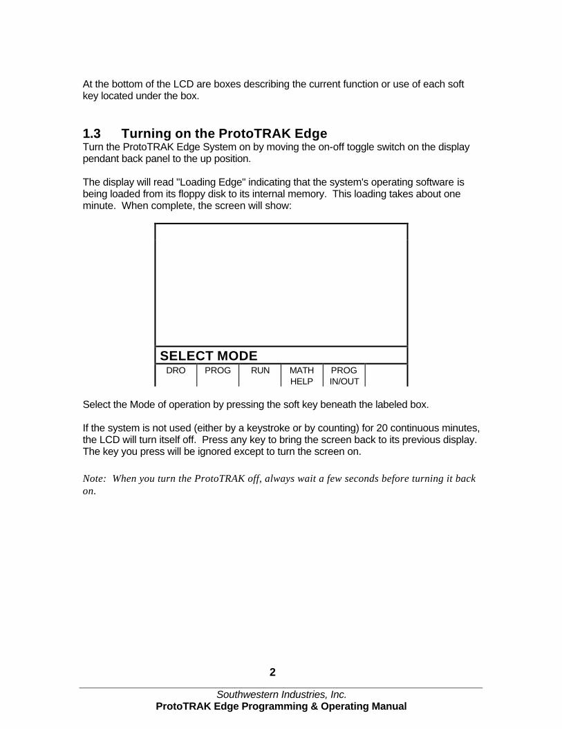
1.3 Turning on the ProtoTRAK Edge Turn the ProtoTRAK Edge System on by moving the on-off toggle switch on the display pendant back panel to the up position. The display will read "Loading Edge" indicating that the system's operating software is being loaded from its floppy disk to its internal memory. This loading takes about one minute. When complete, the screen will show:
SELECT MODE DRO PROG RUN MATH
HELP PROG IN/OUT
Select the Mode of operation by pressing the soft key beneath the labeled box. If the system is not used (either by a keystroke or by counting) for 20 continuous minutes, the LCD will turn itself off. Press any key to bring the screen back to its previous display. The key you press will be ignored except to turn the screen on. Note: When you turn the ProtoTRAK off, always wait a few seconds before turning it back on.
Southwestern Industries, Inc. ProtoTRAK Edge Programming & Operating Manual
2.0 Description
2.1 Display Pendant Front (see Figure 1) Keyboard Hard Keys GO: initiates motion in Run
STOP: halts motion during Run
FEEDéé : feedrate override to increase feedrate
FEED êê : feedrate override to decrease feedrate
MODE: to change from one mode of operation to another
INC/ABS: switches all or one axis from incremental to absolute or absolute to incremental
IN/MM: causes Inch to Metric or Metric to Inch conversion of displayed data
LOOK: part graphics in Program mode
INC SET: loads incremental dimensions and general data
ABS SET: loads absolute dimensions and general data
X, Y, Z: selects axis for subsequent commands
RESTORE: clears an entry, aborts a keying procedure
0-9, +/-, . : inputs numeric data with floating point format. Data is automatically + unless +/- key is pressed. All input data is automatically rounded to the system's resolution.
Soft Keys Beneath the LCD screen are 6 keys that are not labeled. These keys are called software programmable or soft keys. A description of the function or use of each of these keys will be shown at the bottom of the LCD screen directly above each key. If, at any time, there is no description above a key, that key will not operate.
Emergency Stop Switch The emergency stop (E-stop) switch kills all power to the ProtoTRAK's servomotors. The computer and pendant remain powered. The Liquid Crystal Display (LCD) The 7.4" LCD can be adjusted for viewing comfort in two ways. The viewing angle may be changed (see below, Section 2.4) and the contrast may be adjusted using Special Code 160 (see Section 11).
2.2 Pendant Back Panel (see Figure 2) See Figure 2 for a description of the fuses, switches, and connectors on the pendant back panel.
Southwestern Industries, Inc. ProtoTRAK Edge Programming & Operating Manual
2.3 The Floppy Drive Access to the floppy drive is located on the right side of the ProtoTRAK Edge display. A metal plate held by a thumbscrew protects the drive. To change disks, loosen the thumbscrew and swivel the plate up. Press the button on the floppy drive to eject the floppy diskette.
• The System Disk Shipped in the floppy drive is the ProtoTRAK Edge system disk. This disk contains the ProtoTRAK Edge operating program and storage space for your part programs. It is recommended that you make backup copies of this disk on an IBM compatible computer. Use additional disks for additional part program storage.
2.4 The Tilt Adjustment On the left side of the ProtoTRAK Edge display, where the display contacts the pendant arm, are three bolts that allow you to adjust the tilt angle of the display by loosening the nuts. It is necessary to push aside the system cables while you are doing this. Adjust the angle so that the LCD is viewed comfortably and then retighten the nuts.
2.5 Servo Motors/Amplifiers The ProtoTRAK Edge servomotor and amplifier have been combined into a single integrated package on each axis. The motors are rated 280 in-oz. maximum continuous torque that is sufficient for the heaviest cuts.
2.6 Remote Stop Go Switch (optional) For the convenience of operation while running the program, a Remote Stop/Go switch may be purchased. This switch is on a ten-foot cable and operates like the Stop and Go keys on the display.
2.7 The Z Scale (optional) In order to have the Z axis digital readout, it is necessary to have the optional Z-axis scale. The Z readout may be activated or deactivated with Special Code 15.
2.8 Limit Switches (optional) X and Y limit switches may be installed. Given the application, this option is not especially recommended. If the system overruns its travel, even at rapid speed, the resulting bump will normally be absorbed by the system without harm.
X-axis: positive X-axis motion is defined as the table moving to the left when facing the mill. Consequently, measurement to the right is positive on the workpiece. Y-axis: positive Y-axis motion is defined as the table moving toward you. Measurement toward the machine (away from you) is positive on the workpiece. Z-axis: positive Z-axis motion is defined as moving the quill up. Measurement up is also positive on the workpiece.
3.2 Absolute & Incremental Reference The ProtoTRAK Edge may be programmed and operated in either (or in a combination) of absolute or incremental dimensions. An absolute reference from which all absolute dimensions are measured (in DRO and program operation) can be set at any point on or even off the workpiece. To help understand the difference between absolute and incremental position, consider the following example:
3.3 Referenced and Non-Referenced Data Data is always loaded into the ProtoTRAK Edge by using the INC SET or ABS SET key. X, Y, Z positions are referenced data. In entering any X, Y, or Z position data, you must note whether it is an incremental or absolute dimension and enter it accordingly. All other information (non-referenced data), such as tool diameter, feedrate, etc. is not a position and may, therefore, be loaded with either the INC SET or ABS SET key. This manual uses the term SET when either INC SET or ABS SET may be used interchangeably.
3.4 Tool Diameter Compensation Tool diameter compensation allows the machined edges shown directly on the workpiece to be programmed instead of the center of the tool. The ProtoTRAK Edge then automatically compensates for the programmed geometry so that the desired results are obtained.
Southwestern Industries, Inc. ProtoTRAK Edge Programming & Operating Manual
If the cutter in the sketch above is moving from left to right from point X1, Y1 to X2, Y2 and on to X3, Y3, these actual points can be programmed instead of the center of the cutter.
Or, the actual desired circle with radius R can be programmed instead of the radius of the center of the cutter Rc.
Tool cutter compensation is always specified as the tool either right or left of the workpiece while looking in the direction of the tool motion. Examples of tool right are: Examples of tool left are: Tool center means no compensation either right or left. That is, the centerline of the tool will be moved to the programmed points.
3.5 Connective Events Connective events occur between two milling events (either Mill or Arc) when the X, Y, and Z ending points of the first event are in the same location as the X, Y, and Z starting points of the next event. In addition, the tool offset and tool number of both events must be the same.
3.6 Conrad Conrad allows you to program a tangentially connecting radius between connective events, or tangentially connecting radii for the corners of pockets and frames without the necessity of complex calculations. For this figure, you simply program a Mill event from X1, Y1 to X2, Y2 with tool right offset, and another Mill event from X2, Y2 to X3, Y3 also with tool right offset. During the programming of the first Mill event, the system will prompt for Conrad at which time you input the numerical value of the tangentially connecting radius (r=k). The system will calculate the tangent points T1 and T2, and direct the tool cutter to move continuously from X1, Y1 through T1, r=k, T2 to X3, Y3.
Southwestern Industries, Inc. ProtoTRAK Edge Programming & Operating Manual
For this figure, you program an Arc event from X1, Y1 to X2, Y2 with tool offset left, and another Arc event from X2, Y2 to X3, Y3 also with tool offset left. During the programming of the first Arc event, the system will prompt for Conrad at which time you input the numerical value of the tangentially connecting radius r=K3. The system will calculate the tangent points T1 and T2 and direct the tool cutter to move continuously from X1, Y1 through T1, r=k3, T2 to X3, Y3. Note: Conrad must always be the same as or larger than the tool radius for inside corners. If Conrad is less than the tool radius, and an inside corner is machined, the ProtoTRAK Edge will ignore the Conrad.
3.7 Memory and Storage Computers can hold information in two ways. Information can be in current memory or in storage. Current memory (also known as RAM) is where the ProtoTRAK Edge holds the operating system and any part program that is ready to run. While a program is being written, it is in current memory. Storage for the ProtoTRAK Edge is the floppy disk. For programs to be saved for future use, they must be stored on the floppy disk in Program In/Out Mode.
When the ProtoTRAK Edge is first turned on, it reads its operating system into its current memory from the storage location on the floppy disk. At your command, the ProtoTRAK Edge will read any programs you have stored on the floppy disk into current memory for additional programming, editing or running.
If power is lost or turned off, programs that are in current memory are lost, but programs stored on the floppy disk are not.
Southwestern Industries, Inc. ProtoTRAK Edge Programming & Operating Manual
4.0 Using the ProtoTRAK Edge as a DRO The ProtoTRAK Edge operates in DRO Mode as a sophisticated digital readout with jog and power feed capability.
4.1 Enter DRO Mode Press MODE, select DRO soft key. The LCD screen will show:
DRO INCH > STATUS
X 0.0000 ABS Y 0.0000 ABS Z 0.0000 ABS
> INFORMATION
> CONVERSATION JOG TEACH RETURN
ABS 0
SERVICE
CODES
> SOFT KEYS
Note: the RETURN soft key is lit when in Jog. The Z readout display is only active if the ProtoTRAK Edge is purchased with the Z Readout Option and the readout is activated with Service Code 15.
4.2 DRO Functions • Clear Entry: Press RSTR, then re-enter all keys. • Inch to MM or MM to Inch: Press IN/MM and note LCD screen status line. • Reset One Axis: Press X or Y or Z, INC SET. This zeros the incremental position in
the selected axis. • Preset: Press X or Y or Z, numeric data, INC SET to preset selected axis. • Reset Absolute Reference: Press X or Y or Z, ABS SET to set selected axis
absolute to zero at the current position. Note: This will also reset the incremental dimension if the absolute position is being displayed when it is reset.
• Preset Absolute Reference: Press X or Y or Z, numeric data, ABS SET to set the selected axis absolute to a preset location for the current machine position. Note: This will also reset the incremental dimension if the absolute position is being displayed when it is preset.
• Recall Absolute Position of All Axes: Press INC/ABS. Note the dimension for each axis is labeled INC or ABS. Press INC/ABS again to revert to the original reading.
• Recall Absolute Position of One Axis: Press X or Y or Z, INC/ABS. Note the INC or ABS label for each axis. Repeat to get selected axis back to original reading.
Southwestern Industries, Inc. ProtoTRAK Edge Programming & Operating Manual
4.3 Jog The servo motors can be used to jog the table. 1. Press the JOG soft key. 2. The conversation line will read "JOG + 100 ipm" indicating the table will move in the X
or Y positive direction at 100 inches per minute. This message will flash to warn you that JOG is activated.
3. Press +/- to reverse direction. The conversation display will read "JOG - 100 ipm."
Press +/- again to go back to JOG +. 4. Press FEED ê to reduce the jog speed in 10 percent increments. The conversation
line will show these reductions. Press FEED é to increase the speed. 5. Press and hold X or Y to jog that axis. Note the status line will indicate "SERVO ON."
Release the key to stop. 6. To jog at a prescribed rate, for example, to use the jog feature to powerfeed a cut
input the rate (for example, 25 for 25 inches per minute) and press X or Y. Press FEED é or FEED ê to adjust. Press RSTR to return to 100 ipm. In metric this number represents the percent of the maximum, or 2540 mm/min.
7. Press RETURN soft key to return to manual DRO operation.
4.4 Return to Absolute Zero At any time during manual DRO operation you may automatically move the table to your absolute zero location in X and Y by pressing the RETURN ABS 0 softkey. When you do, the conversation line will read "Check Z then press GO." Make sure your tool is clear and press the GO key. When you do, the servos will turn on, move the table at rapid speed to your X and Y absolute zero position, and then turn off. You will be at zero and in manual DRO operation.
Southwestern Industries, Inc. ProtoTRAK Edge Programming & Operating Manual
5.0 Using Teach The Teach function allows you to input a program into the ProtoTRAK Edge by remembering rapid position and feedrate milling events as you machine the first part, or portion of a part. This can be useful for simple operations like facing off a part, clearing out excess material, or remembering a few hole locations. To enter Teach, press the TEACH softkey in the DRO Mode. The display will show:
DRO INCH > STATUS
X 0.0000 ABS Y 0.0000 ABS Z 0.0000 ABS
> INFORMATION
> CONVERSATION
SAVE
POSN
SAVE
MILL
RUN
TEACH
ERASE
TEACH
RETURN > SOFT KEYS
The SAVE MILL softkey will only be activated once an initial position event has been saved. 5.1 Making a Teach Program Only one Teach program can be contained in the ProtoTRAK Edge at any given time. If an existing Teach program is not first erased, more “teaching” will simply add events or moves on to the end of the existing program.
Teach programs are made up of Position events, or moves, and Mill events. Position events are moves at rapid speed and are used to go to the beginning point of a milling move, or to position over a point like a hole for drilling. Mill events are straight line milling moves in the X or Y, or both directions at an input feedrate.
To make a Teach program, follow these procedures:
a) The first event must be a Position move. Crank the X and/or Y handles to the
desired position and press the SAVE POSN softkey. This point will be memorized as the beginning of the program. During Teach Run the machine will move at rapid speed to this first location and stop.
b) If you wish to rapid to the next location, repeat Step a. If you wish to feed or mill, go
to Step c.
c) Mill the part along the X or Y (or both) path using the hand cranks. It’s not important how you get to the end point. In Teach Run the machine will move at the programmed feedrate in a straight line from the beginning point to the end. When at the end point,
Southwestern Industries, Inc. ProtoTRAK Edge Programming & Operating Manual
press the SAVE MILL softkey. The conversation line will prompt “Feedrate 10.0.” You may change the feedrate from the 10 inches per minute default to any value you wish through the numeric keyboard. When the feedrate in the conversation line is what you want, press INC SET or ABS SET to load into memory this position and feedrate.
d) Repeat (a) or (c) above for all other rapid Position events, or feed Mill events you wish. e) In Teach Run the machine will continue from one Mill event directly along to the next
Mill event. You must program a SAVE POSN if you want the machine to stop. f) All events will automatically be saved with Tool Number 99. g) All Mill events will be saved with Tool Center Offset (see Section 3.4).
5.2 Running a Teach Program A Teach Program is run from the DRO Mode.
To run a Teach program, press the RUN TEACH softkey from the screen above. Follow the same procedures for running a regular program as described in Section 8.0.
Note: When you use Position to go to the beginning of a Mill move, you will have to hit GO twice to begin the milling move.
5.3 Erasing a Teach Program The ProtoTRAK Edge may contain only one Teach Program. To input another, you must first erase the one that exists.
To do so: Press the ERASE TEACH softkey, then select the YES softkey.
Southwestern Industries, Inc. ProtoTRAK Edge Programming & Operating Manual
6.0 Programming The ProtoTRAK Edge can be programmed to make just about any part in two axes. A program is one or a series of events. It can either be a complete part, a set of operations on a side or only a small number of cuts. It is necessary to create a program when you want the CNC to machine the part for you.
6.1 Enter Program Mode and Assign a Part Number To start programming, press MODE and select PROGRAM softkey. For a new program to be written, there cannot already be a program in the active or current program memory. If a program does not already exist when you enter the Program Mode, the conversation line will read "Program Part Number." Enter a part number of your choice (up to 8 digits) and press INC SET or ABS SET. Note: It is not necessary to enter a part number. If none is entered and the INC SET or ABS SET button is pushed, the system will assume a part number 0. The ProtoTRAK Edge automatically holds all of the completed events as you program in current memory. If there is already a program when the Program Mode is entered, the last event of this program will appear on the left side of the screen. Additional events may be added after the last event of this program. It will be necessary clear the program from current memory before creating a new program. See Section 10 for the procedures for saving and clearing programs. When a new Part Number (for a new program) has been entered, the display will show the Select Event screen:
PROG P/N 12345 INCH > STATUS
EVENT1
> INFORMATION
SELECT EVENT >
CONVERSATION POSN
DRILL
MILL ARC POCKET
FRAME
REPEAT PAGE
BACK >SOFTKEYS
6.2 Programming Strategy and Procedures The ProtoTRAK Edge makes programming easy by allowing you to program the actual part geometry as defined by the print. The Select Event screen is basically a list of all the types of geometry that can be machined with a two-axis control on a mill.
Southwestern Industries, Inc. ProtoTRAK Edge Programming & Operating Manual
The basic strategy is to select the softkey event type (geometry) and then follow all instructions in the conversation line. When an event is selected, all the prompts that need to be input will be shown on the right side of the information area. The first prompt will be highlighted and also shown in the conversation line. Input the dimension or data requested and press INC SET or ABS SET. For X or Y dimension data it is very important to properly select INC SET or ABS SET. For all other data either SET will do. As data is being entered it will show in the conversation line. (If you make a mistake, for example, you press the wrong number key, you can clear the input by pressing RESTORE.) When SET, the data will be transferred to the information area, and the next prompt will be shown in the conversation line. From the event data screen you may press the DATA FWD or DATA BACK softkeys to go back to edit any data within an event. Simply shift forward or back to get the prompt in the conversation line and reinput the data. At any time before the event is complete you may cancel the event by pressing the ABORT EVENT softkey. You may also press the PAGE BACK softkey that will shift you back to the previous events so that you can make any changes you wish. When all data for an event has been entered, the entire event will be shifted to the left side of the screen and the conversation line will ask you to select the next event.
6.3 Programmed Events The following events are found in the ProtoTRAK Edge. 6.3.1 Posn Drill This will position the table and saddle to the location you define. This event is used for drilling holes and other positioning moves. When you press the POSN/DRILL key, you choose between:
• One: a single position. • Bolt Hole: a series of positions spaced evenly around a circle.
When the program is run at a Posn/Drill Event, the ProtoTRAK Edge will servo at rapid (or as modified by you) to each location defined and will wait for you to finish the operation (e.g., drill the hole) and press the GO key before moving on. 6.3.2 Mill Event Use this to machine a straight line in any direction. The prompts you answer in this event will allow the ProtoTRAK Edge to calculate the complete tool path, including the starting position and tool offsets. It is not necessary to program a rapid move to the beginning position of the Mill Event. When the program is run at a Mill Event, the ProtoTRAK Edge will rapid to the beginning position, move through the Mill Event at the speed you program and end at the ending position. (See the discussion on Continue below for the variation in tool motion if the event is connective).
Southwestern Industries, Inc. ProtoTRAK Edge Programming & Operating Manual
6.3.3 Arc Event This is any part of a circle. Like the Mill Event, the prompts you answer will allow the ProtoTRAK Edge to calculate the complete tool path. When the program is run at an Arc Event, the ProtoTRAK Edge will rapid to the beginning position, move through the Arc Event at the speed you program and end at the ending position. (See the discussion on Continue below for the variation in tool motion if the event is connective). 6.3.4 Pocket/Frame Event Use this event to machine a pocket or frame with a minimal amount of programming. When you press the Pocket/Frame key, you choose between the following:
• Circle pocket: a circle and all the material in the center. Includes finish cut.
• Rectangular pocket: a rectangle and all the material in the middle. Includes finish cut.
• Circle frame: a circular circumference. Includes finish cut.
• Rectangular frame: a square or rectangular circumference. Includes finish cut.
When the program is run at a Frame Event, the ProtoTRAK Edge will rapid from wherever it is to the nearest point on the circle or rectangle. After you set the cutter and press go, it will move through the first pass and then the finish cut at the programmed feedrate and then move the cutter away from the part by the amount of the programmed finish cut. A Posn/Drill event may be inserted to change the beginning point of the machining. The Pocket Event will rapid to the center of the circle or rectangle. After you set the cutter and press GO, it will move in a logical path through the material (leaving the finish cut, if one is programmed), using 70% of the cutter diameter. After the center is cleared, it will do the finish cut and ramp away from the part at the end by the amount of the programmed finish cut. 6.3.5 Repeat Events This allows you to repeat an event or a group of events up to 99 times, with an offset in X or Y. This can be useful for drilling a series of evenly spaced holes, duplicating some machined shapes or even repeating an entire program with an offset for a second fixture. Another use is to repeat a programmed set of drill events (without offsets) so you can center drill, drill, and counterbore without reprogramming the second and third operations. Repeat events may be "nested" up to five deep. That is, you can repeat a Repeat Event, of a Repeat Event, of a Repeat Event of some programmed event(s). One new tool number may be assigned for each Repeat Event.
6.4 Prompts Used to Define the Events The following prompts are encountered in programming the events.
# Holes - the number of holes in the bolt hole pattern.
Angle - the location of the first hole to be machined in a Bolt Hole event. It is the angle from the positive X axis (that is, 3 o'clock) to the hole. The positive angle is measured counterclockwise from 0.000 to 359.999 degrees.
Southwestern Industries, Inc. ProtoTRAK Edge Programming & Operating Manual
Conrad - There are two meanings to Conrad: 1. The connecting radius between line or arc being programmed and the next line or arc event. Simply enter the radius value at this prompt and the ProtoTRAK Edge will figure the tool path to go from one event to the next with a connecting radius. If no radius is desired, or if you are programming the last event, enter 0 by pressing the INC SET or ABS SET key without a number value. 2. The corner radius in a rectangular pocket or frame. The radius is tangential.
Continue - to tell the ProtoTRAK Edge if the event is continuous to the next event(s) to be programmed. This saves inputs needed to define a profile. If the event is programmed with a Yes, for continue, then X begin, Y begin, Tool Offset, Feedrate and Tool # will not be prompted in the next one.
Direction - for an arc or circle, the direction is clockwise or counterclockwise.
Feedrate - the milling feedrate in in/min from .1 to 99.9 or in mm/min from 5 to 2500.
Fin cut - for a pocket or frame, the width of the finish cut. If 0 is input, there will be no finish cut.
Radius - the radius of the bolt hole pattern, arc or circle.
Tool # - the number you assign to identify the tool.
Tool Diameter - the diameter of the tool. See the note on finish cuts later in this section.
Tool offset - the selection of the tool offset, right, left or center relative to the programmed edge or tool movement.
X or Y - the X or Y dimension, may be defined in absolute or incremental reference.
X Begin or Y Begin - the X or Y beginning point of the line or arc.
X Center or Y Center - the X or Y dimension of the center of the bolt hole pattern, arc or circle.
X End or Y End - the X or Y ending point of the line or arc.
X1, Y1, and X3, Y3 - the X and Y dimensions for the opposite corners on a rectangular pocket or frame.
Prompts unique to the Repeat event:
First Event # - the first event to be repeated. Last Event # - the last event to be repeated. If only one event is to be repeated, the First and Last events will be the same number.
X Offset - the incremental X offset from the event to be repeated.
Y Offset - the incremental Y offset from the event to be repeated.
# Repeats - the number of times the events are to be repeated up to 99.
Southwestern Industries, Inc. ProtoTRAK Edge Programming & Operating Manual
6.5 Continue In MILL and ARC events the ProtoTRAK Edge will ask you to choose YES or NO to the continue prompt. If you want the cutter to keep machining from the event you are programming to the next event without stopping, you should choose YES. If you want the cutter X/Y motion to stop so that you can adjust Z quill position, then choose NO. If you choose NO, then any programmed CONRAD will be ignored (because CONRAD assumes you are continuing on to the next event), and in PROGRAM RUN Mode the motion will stop. If you choose YES, then the next event must be a connective event. Prompts for the X Beginning location, Y Beginning location, Tool Offset, Feedrate, and Tool # will not be asked because, if the events are connective, this data is already known. The programmed feedrate may be different for different events, even when the events are connective. To change the feedrate within a group of connective events, finish programming the event and then use the PAGE BACK key. See Section 7.4.
6.6 Assumed Tool Offset, Feedrate, and Tool # When the INC SET key is pressed, the ProtoTRAK Edge will automatically program the following for these prompts: TOOL OFFSET: for a Mill or Arc Event, same as the last event if that event was a Mill or Arc Event, otherwise, Tool Center. FEEDRATE: same as last event if that event was a Mill, Arc, Pocket, or Frame, otherwise, 1.0 in/min or 25 mm/min. TOOL #: same as last event, or Tool 1 in the first event. You may change these assumed inputs by simply inputting the correct data when the event is programmed.
6.7 Incremental Reference Position When X and Y data for the beginning position of any event are input as incremental data, this increment must be measured from some known point in the previous event. Following are the positions for each event type from which the incremental moves are made in the subsequent event:
Southwestern Industries, Inc. ProtoTRAK Edge Programming & Operating Manual
CIRCLE POCKET or FRAME: X CENTER and Y CENTER programmed
RECTANGLE POCKET or FRAME: X1 and Y1 corner programmed position
REPEAT: The appropriate reference position for the event prior to the first event that was repeated.
6.8 Finish Cuts The Pocket and Frame events are designed with built-in finish cut routines because they are complete, stand-alone pieces of geometry. Shapes machined with a series of Mill or Arc events don't have an automatic routine for making finish cuts. Instead, it is very easy to get a finish pass by overstating the size of the tool for the events in the initial pass, and then using a Repeat Event and programming a new tool with the actual size of the tool.
For the first pass, the cutter will be positioned away from the final cut half the amount of the difference between the actual size of the cutter and the diameter you put in. When the Repeat Events are run, the same cutter will be positioned correctly to do the final pass to size.
6.9 Look You can look at part graphics while in the Program Mode. At any time an event is finished programming and the Select Event prompt appears in the conversation line, simply press the LOOK hard key. The programmed events are automatically sized so that everything fits on the screen.
To return to the programming, press the RETURN softkey.
The part graphics are useful for checking what you have programmed so far. Certain kinds of programming mistakes are not caught by the graphics. These will surface when running the program.
6.10 A Sample Program This simple part will be used to illustrate the process of programming.
Steps 1. Decide the order of machining. This part can be held in a vise. First we will drill the
two holes and then we will mill the slot.
2. Decide the Absolute reference. In this case we will use the lower left corner as our 0 location for X and Y.
Southwestern Industries, Inc. ProtoTRAK Edge Programming & Operating Manual
3. Enter the Program Mode. If there is already a program in the current memory, go into the Program In/Out Mode and press the CLEAR CURRENT softkey. (You may want to store the program in current memory first.)
4. Assign a part number. When there is no program in the current memory, the system will prompt for a program part number as soon as it goes into Program Mode. Enter a numeric part number (or not, if you don't want one) and press SET.
5. Program the first hole. Prompt You push these keys
SELECT EVENT POSN/DRILL SELECT ONE X .75 ABS SET Y 2. ABS SET Tool # 1 INC or ABS SET Tool Dia .1 INC or ABS SET
Notes: • For the non-referenced data, either SET key will do. • This first tool is a center drill. For the Position/Drill Event, the program will run
without a tool diameter, but one may be entered as a reminder.
6. Program the second hole. Prompt You push these keys
SELECT EVENT POSN/DRILL SELECT ONE X 1. INC SET Y INC SET Tool # INC SET Tool Dia INC SET
Notes: • For the dimensions, it was handy to read these right off the print and put them in as
incremental moves from the previous hole. We could have also programmed using X = 1.75 ABS SET and Y = 2.0 ABS SET.
• The INC SET entry for Y was taken as a 0 incremental move, you do not have to press 0.
• The INC SET for the Tool # and Tool Diameter were taken as "use the data from the previous event."
7. Repeat the holes to drill to size. Prompt You push these keys SELECT EVENT REPEAT First Event # 1 INC or ABS SET Last event # 2 INC or ABS SET X offset INC SET Y offset INC SET No. of Repeats 1 INC or ABS SET Tool # 2 INC or ABS SET Tool Dia .25 INC or ABS SET
Southwestern Industries, Inc. ProtoTRAK Edge Programming & Operating Manual
Note: We want to visit the same two holes, in the same place, with a different tool to do the final drilling.
8. Look at what you have programmed. Press the LOOK key. You will see two + marks on opposite sides of the screen to show where the holes have been programmed. Press RETURN to get back to the programming.
9. Program the slot.
Prompt You push these keys SELECT EVENT MILL X Begin 4.25 ABS SET or 2.5 INC SET Y Begin .8 ABS SET X End INC SET Y End 1.3, INC SET Conrad INC SET Tool Offset 0, INC or ABS SET Feedrate 7.5, INC or ABS SET Continue 0, INC or ABS SET Tool # 3, INC or ABS SET Tool Dia .375, INC or ABS SET
10. Look at the program again. If all went well, you should now see the two holes and slot
tool path in the same proportion as they appear on the print. If not, check your inputs and try again.
When you machine the part, you will probably want to use a drill to open up a hole at the beginning of the slot for your milling tool. To do that, you can either: • program a position event for the drill, or • when the ProtoTRAK Edge positions at the beginning of the slot, center drill and
drill first, then put in your mill.
If you have a lot of parts to do, it is worth your while to add the drill into the program, but probably not if you only have one or two. The great thing about the ProtoTRAK Edge is you don't have to make it part of the program. It still does the positioning for you and you have the flexibility to do the drill operations before you press the GO button for the milling.
Southwestern Industries, Inc. ProtoTRAK Edge Programming, Operating & Care Manual
7.0 Changing or Correcting Programs In the Program Mode, you can easily correct mistakes or make changes to the program.
7.1 Aborting a Partially Programmed Event If you wish to not program an event (or start over) after you have started to program, press the ABORT EVENT softkey and the screen will revert to the "Select Event" prompt.
7.2 Editing Data while Programming an Event All data is entered by pressing the appropriate numeric keys and pressing INC SET or ABS SET. If you enter an incorrect number before you press INC SET or ABS SET you may clear the number by pressing RESTORE. Then, input the correct number and press SET. If incorrect data has been entered and SET, you may correct it as you are still programming that same event by pressing the DATA BACK or DATA FWD (Forward) softkey until the incorrect prompt and data are highlighted and shown in the conversation line. Enter the correct number and SET. The ProtoTRAK Edge will not allow you to skip past prompts (by pressing DATA FWD) that need to be entered to complete an event.
7.3 Editing Previously Programmed Events From the Select Event screen you may press the PAGE BACK softkey and the program will move back one event. For example, if you have already programmed 10 complete events and you pushed the PAGE BACK key, Event 10 will move to the right side of the screen and Event 9 will be shown on the left. The softkey options are:
ADD
EVENT
DELETE
EVENT
DATA
FWD
DATA
BACK
PAGE
FWD
PAGE
BACK
Where:
ADD EVENT allows you to insert a new event between the two shown on the left and right side of the screen. When you press ADD EVENT the screen will revert to the Select Event screen and you may program the new added event as you would any other. Subsequent events will be renumbered accordingly. DELETE EVENT allows you to delete the event on the right side of the screen. Subsequent events will be renumbered accordingly. DATA FWD (Forward) steps the highlight and conversation line to the next prompt and data so it can be edited. DATA BACK steps the highlight and conversation line to the previous prompt. PAGE FWD (Forward) indexes the event forward by one.
Southwestern Industries, Inc. ProtoTRAK Edge Programming, Operating & Care Manual
7.4 Changing the Feedrate If the feedrate is edited in any event it will automatically be edited in every subsequent and contiguous event with the same tool number and feedrate. For example, let's say events 5 through 10, and 13 through 16 were all programmed with tool number 2, and 5 inches per minute feedrate. If you edit the feedrate in Event 7 to 3 inches per minute, it will automatically change Events 8, 9, and 10 also. Events 5, 6, 13, 14, 15, and 16 will not be affected
7.5 Changing a Part Number (making a copy of a program) You may want to rename a part program, or make a copy of a program using a different name. The latter may be useful if you have a new part to do that is similar to a part that you already have programmed. Make a copy of the program by saving it under a new part number and then make the changes.
You can rename a part program when it is not yet stored on the floppy disk in the Program Mode by pressing the DATA BACK key past the first event until you are at the prompt for Program Part Number. Enter the new part number and press SET. If the program is long, it is better to rename it in the Program In/Out Mode. After pressing the PROG IN/OUT key, simply enter the new part number and press STORE.
If the previous part program is already stored on the floppy disk, it will remain in storage under the previous part number with the same information it had the last time it was stored.
7.6 Saving Changes to a Program
If a program is retrieved from storage and changes are made, the program must be stored again in Prog In/Out Mode for the changes to be preserved in the stored copy. Programs in current memory may be changed and run with the changes, but unless they are re-stored, the changes made will be lost when the program is cleared from current memory. If you intend to keep the changes made to your program it is a good practice to store the program occasionally in case a power loss causes the program to be ejected from current memory.
7.7 Erasing an Entire Program To erase an entire program from current memory, go to the Program In/Out Mode and press CLEAR CURRENT. You will be prompted "Are you sure you want to erase this program?" You may want to store the program on the floppy disk before you clear it from current memory. If it is not stored on the floppy, pressing YES will permanently erase the program.
To erase an entire program from the floppy storage, input the part number and then press ERASE. Programs in current memory will not be affected by this operation. You could erase a part number on the floppy and the program in current memory will remain in current memory, even if it has the same part number as the one just erased.
Only programs with the .mx2 extension may be erased from the floppy by the ProtoTRAK Edge, CAM programs must be erased by another computer.
Programs in current memory will automatically be erased when another program is retrieved from storage.
Southwestern Industries, Inc. ProtoTRAK Edge Programming, Operating & Care Manual
8.0 Making Parts with the CNC
8.1 Setting Up Before you can run your program, you must set your absolute position in the DRO Mode. The CNC will use this absolute position as a reference for running your program.
8.2 Starting After setting up in the DRO Mode, go into the Run Mode. You will see this screen:
RUN P/N 12345 INCH
X 0.0000 ABS Y 0.0000 ABS Z 0.0000 ABS FEEDRATE 100.00 OVERRIDE 100% SELECT
START
START EVENT #
The part number appears in the status line.
To start the program, select between START and START EVENT#. • START – starts running the program from the beginning. • START EVENT # – starts running the program from an event in the middle. If you press
this key, the INPUT EVENT # prompt will appear for you to choose where to start.
8.3 Display Messages in Program Run
SERVO ON: appears in the status line when the servo motors are on. IN POSITION: appears in the status line when the program has come to a pause. EVENT # and type: appears above the X dimension. This is the current or next event to be run. If the IN POSITION message is not already on, the next move made by the ProtoTRAK Edge will be to rapid to the beginning of the event shown. FEEDRATE: the actual table feedrate. OVERRIDE: the feedrate override, controlled by pressing the FEED hard keys.
Southwestern Industries, Inc. ProtoTRAK Edge Programming, Operating & Care Manual
8.4 Program Run Prompts During Program Run, all messages that will help you to run the part will appear in the conversation line. The messages you will usually see are: Load Tool __ __: Means to load the tool requested and press GO to continue.
Check Z: Means to make sure the quill is properly retracted because the next move will be rapid. Press GO to continue.
Set Z: Means to drill and retract the quill for a drilling operation, or set and lock the quill to the proper depth for a milling cut. Press GO to continue.
Run Over: Means that the program run is complete. If you are running a second part that will be fixtured/clamped in the exact same position as the first part, you do not need to relocate the absolute 0 and restart. Instead, press the NEXT PART softkey when the conversation line states "Run Over" and the system will proceed directly to Event 1.
8.5 Stop At any time, pressing the STOP key will halt the program. This freezes the program at that point. To continue, press the GO key.
8.6 Feedrate Override The run feedrate may be changed at any time by pressing the FEED é or FEED ê keys. Each press changes the programmed feedrate, and rapid in 10% increments. The maximum overrides are from 10% to 150% of programmed feedrates.
8.7 Trial Run Before cutting material, it is recommended that you do a trial run by keeping the quill up while the program runs through. Verify that the absolute reference is set correctly.
8.8 Data Errors A program must make sense geometrically. For example, you can't machine a .250 inch diameter circular pocket using a .500 inch end mill. Data errors will nearly always be detected when the ProtoTRAK Edge runs through a program--either as a trial run or on an actual part run. The Conversation Line displays the error number (not necessarily important to you) and the event where the error was detected. This is not necessarily the event that is in error since the system often "looks ahead" to make sure there is compatibility from one event to another. In addition, an explanation is given for each data error type as well as a suggested solution.
8.9 Fault Messages The ProtoTRAK performs a number of automatic checks or self-diagnostics. If problems are found it will signal you through the display. The conversation line will display "Fault __ __ __ __". The information area will display an explanation and suggested solution. Press the RETURN key to get back to the Select Mode screen.
Southwestern Industries, Inc. ProtoTRAK Edge Programming & Operating Manual
9.0 Math Help Prints are, unfortunately, not always drawn and labeled in such a way as to provide all of the points necessary for programming. To minimize this problem, the ProtoTRAK Edge provides a graphic math help function which can be used to automatically calculate points of intersection, centers of arcs, trig functions, square roots, etc.
9.1 Procedure To enter the Math Help Mode, press MODE and select the MATH HELP soft key. The screen will show:
MATH INCH > STATUS
A Line-Line Intersection B Line-Arc and Arc-Arc Intersection C Line-Arc Tangency D Centers, points, Radius, Angles of Circles E Polar-Cartesian Transformations
> INFORMATION
SELECT > CONVERSATION
A
B
C
D
E
TYPE # > SOFT KEYS
If you already know the math help type you want (see Section 9.2) press the TYPE # softkey and enter the number and SET. If you do not know the type, select from A through E using the softkeys. If, for example, you wish to find the intersection of a straight line and an arc or circle, press the B softkey. The screen will show:
MATH Line-Arc Intersection INCH > STATUS
TYPE 13 TYPE 14
Find the intersection of a line and an arc when 2 points are known on the line, and the arc’s center and radius are known Find the intersection of a line and an arc when 2 points are known on the line, two points are known on the arc, and the arc radius is known
Southwestern Industries, Inc. ProtoTRAK Edge Programming & Operating Manual
If the information you know about the line and arc correspond to Type 13, then select the 13 softkey. The screen will then show:
MATH Line-Arc Intersection INCH > STATUS
X1 Y1 X2 Y2 X CENTER Y CENTER R1
> INFORMATION
X1 > CONVERSATION
DATA
FWD
DATA
BACK
ABORT
TYPE >SOFT KEYS
Input the known data in the same way you would program an event. When all of the data is entered, the solution (or solutions if there are more than one) will be shown on the left side of the information area. There are often multiple solutions for geometry problems. For example, in the Type 13 example above, a line will often intersect an arc or circle in two places. In these cases all possible solutions will be calculated and displayed. In most cases a careful inspection of the print and some common sense will tell you which solution applies to your problem.
9.2 Math Help Types Type # What you need What you know
10 Intersection of two lines • 2 points on each line 11 Intersection of two lines • 2 points on one line
• 1 point on the other line • angle between the lines
12 Intersection of two lines • 2 points on one line • 1 point on the other line • a radius tangent to both lines when one of
the points on the two points known line is also on the radius
13 Intersection of a line and an arc • 2 points on the line • arc center • arc radius
14 Intersection of a line and an arc • 2 points on the line • 2 points on the arc • arc radius
15 Intersection of two arcs • center of each arc • radius of each arc
Southwestern Industries, Inc. ProtoTRAK Edge Programming & Operating Manual
Type # What you need What you know 16 Intersection of a line tangent to two arcs
(line does not cross arc centers) • center of each arc • radius of each arc
17 Intersection of a line tangent to an arc • one point on the line • center of the arc • radius of the arc
18 Intersection of a line tangent to two arcs (line crosses arc centers)
• center of each arc • radius of each arc
19 Center and points of intersection of an arc tangent to two arcs
• 2 of the arc centers • all 3 radii
20 Center of an arc • 2 points on the arc • radius of the arc
21 Point on an arc • center of the arc • another point on the arc • angle between known and unknown
points 22 Radius of an arc or circle • 1 point on the arc
• center of the arc 23 Center of an arc or circle • 2 points on the arc
• angle between the 2 points 24 Center and radius of an arc or circle • 3 different points on the arc 25 Cartesian (X and Y) location • polar (R and angle) coordinates 26 Angle in decimal • angle degrees, minutes and seconds 27 Accurate X Y Center • given X Y Center
• 2 points on the arc 28 Sides and angles of a right triangle • at least one side and another side or an
Southwestern Industries, Inc. ProtoTRAK Edge Programming, Operating & Care Manual
10.0 Program Memory & Storage The ProtoTRAK Edge can only have one program at a time in current memory. This is the program you see when you enter the program mode and is the one that is available to run. Programs may be stored for future use on the floppy disk included with the ProtoTRAK Edge. The disk is accessible through the door on the side of the pendant. Part programs are saved to the floppy or retrieved from the floppy in the Program In/Out Mode. When programs are transferred back and forth from current memory and storage, they stay in both locations unless erased or cleared. In other words, retrieving a program from the floppy disk into the current memory does not remove it from the floppy disk. Only erasing the program will remove it.
10.1 Cautions About Storing and Retrieving Programs Care must be taken to keep from losing a program you wish to keep. This can happen two ways. First, whenever a program is retrieved, it is loaded into the ProtoTRAK Edge's computer program memory. When this happens, your existing current program is erased. Therefore, if your current program is one you want to keep, be certain to store it before you retrieve another program. Second, to store a program it must have a part number so that the ProtoTRAK Edge can find it if you want it retrieved. However, no two programs can have the same part number (how would the system decide which to retrieve?). Therefore, if you store a program with any particular part number, it will automatically erase any other program with that same part number.
10.2 Program Formats and Labeling The ProtoTRAK family of products has its own unique programming system--one that organizes the program into events rather than codes and blocks. Programs written on a two-axis milling control (such as the ProtoTRAK Edge) will have the extension .MX2. The ProtoTRAK Edge software will accept an RS274 CAD/CAM generated program (as configured through a post processor similar to a Fanuc 6) and convert it to an Edge event type program. This can occur by generating the properly post processed program in your computer, copying it onto a spare Edge floppy disk, and loading that disk into the ProtoTRAK (see Section 10.3). Note: All CAD/CAM generated programs must be labeled at the computer with one to eight numerical digits followed by a decimal point, followed by CAM (for example, 123.CAM or 87654321.CAM). If these rules are not followed, the Edge will not recognize the program.
• All part numbers in the ProtoTRAK Edge floppy disk are listed in the Information Area.
The listing shows the part numbers followed by MX2 if they were generated through the ProtoTRAK Edge, or they are followed by CAM if they were generated through a CAD/CAM system.
• The part number of the current program (in current memory) is shown in the conversation
line. You may change the part number at this screen by entering a new number and pressing STORE.
• The PAGE FWD (Forward) softkey will continue the part number list if there are too
may to be shown on the screen. • STORE will write the program in current memory to the floppy. You will see the
program added to the list in the information area after it is stored.
• RETRIEVE MX2 will write a .MX2 program from the floppy to current memory. First input the part number and then press the RETRIEVE MX2 key.
• ERASE will erase a program from the floppy. First input the program number and then press the ERASE key. Note: You may not erase a CAM file using the ERASE key.
• CLEAR CURRENT will erase the program from current memory. You do this to clear
Southwestern Industries, Inc. ProtoTRAK Edge Programming, Operating & Care Manual
• RETRIEVE CAM will write a .CAM program from the floppy to current memory. First input the part number and then press the RETRIEVE CAM key.
Notes:
• You may have two programs with the same part number if one is .MX2 and the other is .CAM. The different extensions make them different programs.
• When CAM filed are brought into the ProtoTRAK Edge, the information is converted (or parsed) into ProtoTRAK events. You may edit the program in this format.
• If a .CAM program is saved in the program IN/OUT Mode, the part number remains the same, but the extension is changed to .MX2.
10.4 Changing Floppy Disks The 1.4 mb floppy disk drive is located in the ProtoTRAK Edge display pendant and is easily accessed through the door on the side of the display. The floppy disk holds ProtoTRAK Edge system software as well as the part programs. Therefore, the system will not "boot up" or turn on unless there is a disk loaded in the drive. Each ProtoTRAK Edge is shipped with a disk loaded in the drive and a spare disk. All contain the system software and one program used to test the product. If you plan to generate and save a large number of programs, or if you plan to use CAD/CAM-generated programs, we strongly recommend you make several additional copies. If you wish to remove a disk: a. Rotate the cover away from the drive on the side of the display b. Press the button on the drive to eject the disk. c. Remove the disk. If you wish to load a disk: a. Rotate the cover away from the drive on the back panel. b. Push the disk in gently until the eject button pops out. If you wish to load a CAD/CAM generated program: a. Write a program using your CAD/CAM and Edge compatible post processor. Be sure to label the program with one to eight numerical digits, followed by a decimal point, followed by CAM (for example 123.CAM). b. Load any IBM compatible disk into your computer. c. Load the program onto the above disk. d. Insert the disk into the ProtoTRAK Edge and retrieve the program as described in Section 10.3. Note: Any disk can be used for program storage, but only the ProtoTRAK Edge system disk can be used to boot up the control.
Southwestern Industries, Inc. ProtoTRAK Edge Programming, Operating & Care Manual
11.0 Service Codes Service codes are special codes used infrequently for set-up or installation of the ProtoTRAK Edge.
11.1 Service Code Procedure Go to the DRO Mode. Press SERVICE CODES. Input one of the codes from the list in section 11.2 Press SET. For some of the codes, there are additional instructions.
11.2 Service Code Types Code Description Notes
12 Determine feed forward constant
Runs a routine that determines the system friction for setting feed forward constant. Caution! Do not use this code unless you understand the consequences. For more details, see SWI Publication No. 22059 "ProtoTRAK Edge Installation and Service Manual."
13 Reset the default feed forward constant
In case you ignored the warning above, this resets the default set at the factory.
15 Activate or Deactivate Z readout
The Z-axis readout should be activated if you installed the optional Z-axis scale. This may be added to your system at any time and the Z readout activated by this code.
22 Turn on simulation For demo purposes, the ProtoTRAK Edge may be run in simulation mode where the control operates normally but does not send commands to the motors. If you use this code, don't forget to restore your CNC to normal operation with Service Code 89!
33 Software ID Displays the version of software your ProtoTRAK Edge is using.
54 Continuous run mode Keeps running the system through the program without stopping. It is used for testing.
66 Metric default To have the ProtoTRAK Edge power up in Metric measurement.
67 Inch default To have the ProtoTRAK Edge power up in Inch measurement.
68 0.01mm / 0.0005" display DRO resolution. 69 0.01mm / 0.001" display DRO resolution. 79 Turn on beeper Factory setting. 80 Turn off beeper For stealthy machining. 81 Keyboard test For testing. 89 Cancel simulation Cancel the Service Code 22 simulation.
Southwestern Industries, Inc. ProtoTRAK Edge Programming, Operating & Care Manual
Code Description Notes 97 Axis configuration To orient the motor encoder. This should not
need to be done except in a service situation. 99 Master reset and program
clear Resets all the values. Be sure you understand the consequences before you use this code. See SWI Publication No. 22059 "ProtoTRAK Edge Installation and Service Manual."
100 Axis open loop test Runs selected axis at rapid for one second and displays values. Caution! The machine will move. Be sure you understand the consequences before you use this code. See SWI Publication No. 22059 "ProtoTRAK Edge Installation and Service Manual."
123 Calibration of each axis of measurement.
Detailed instructions are found in SWI Publication No. 22059 "ProtoTRAK Edge Installation and Service Manual."
125 Display calibration factors See SWI Publication No. 22059 "ProtoTRAK Edge Installation and Service Manual."
127 Single encoder backlash calibration
Used to calculate a backlash value for entering in Code 128. See SWI Publication No. 22059 "ProtoTRAK Edge Installation and Service Manual."
128 Enter backlash value Used to enter the backlash value calculated using Code 127. See SWI Publication No. 22059 "ProtoTRAK Edge Installation and Service Manual."
142 Save control parameters Used when updating software with a new system disk. See SWI Publication No. 22059 "ProtoTRAK Edge Installation and Service Manual."
160 Adjust LCD contrast For viewing comfort, the display LCD contrast may be adjusted.
Southwestern Industries, Inc.
Trav-A-Dial & TRAK
Warranty Statement Trav-A-Dial and TRAK products are warranted to the original purchaser to be free from defects in workmanship and materials for the following periods:
Product Warranty Period
Materials Factory Labor
New Trav-A-Dial 1 Year 1 Year New TRAK 1 Year 1 Year Any Exchange Unit 90 Days 90 Days
The warranty period starts on the date of the invoice to the original purchaser from Southwestern Industries, Inc. (SWI) or its authorized distributor. If a unit under warranty proves to be defective in workmanship or materials, it will be repaired or exchanged at our option for a properly functioning unit in similar or better condition. Such repairs or exchanges will be made FOB Factory/Los Angeles.
Disclaimers of Warranties ♦ This warranty is expressly in lieu of any other warranties, express or implied, including any
implied warranty of merchantability or fitness for a particular purpose, and of any other obligation or liability on the part of SWI (or any producing entity, if different).
♦ Warranty repairs/exchanges do not cover incidental costs such as installation, labor, freight, etc.
♦ SWI is not responsible for consequential damages from use or misuse of any of its products, even if SWI has been notified of the possibility of such damages.
♦ Trav-A-Dial/TRAK products are precision mechanical/electromechanical measurement systems and must be given the reasonable care that these types of instruments require:
◊ Proper shop facilities are the responsibility of the customer. This warranty does not apply if the facilities, e.g., flooring or electricity, are not adequate for the installation and use of the products.
◊ Proper use of shop equipment such as air hoses. Consequently, the warranty does not
apply if the customer uses poor machine shop practices and blows chips into machine gibs, glass scale, and TRAK Sensor or control instruments.
◊ Proper maintenance and lubrication as directed in the product manual is the
responsibility of the customer. This warranty does not apply if the customer does not properly maintain the unit.
♦ Accidental damage, beyond the control of SWI, is not covered by the warranty. Thus, the
warranty does not apply if an instrument has been abused, dropped, hit, disassembled or opened.
♦ Improper use or installation by or at the direction of the customer in such a way that the product
consequently fails is considered to be beyond the control of the manufacturer and outside the scope of the warranty.