A SINGLE STEP PRESSURE REGULATION SYSTEM FOR THE NATURAL GAS MOTORCYCLE Rahmat Mohsin, Zulkefli Yaacob, Zulkifli Abdul Majid and Shameed Ashraf Gas Technology Centre (GASTEG) Faculty of Chemical and Natural Resources Engineering Universiti Teknologi Malaysia 81310 UTM Skudai, Johor Darul Takzim, Malaysia. Tel.: 07-5535653 Fax.: 07-5545667 [email protected]ABSTRACT The use of Compressed Natural Gas (CNG) for vehicle has proved to improve emission quality, reduces dependency on mainstream fuels and increase lubrication oil lifespan. The successful utilization of CNG on the Kriss Modenas 110cc has been proven by previous researcher. The current study is carried out in the attempt to improve the pressure regulator which is deemed crucial in the CNG fuel system. Various drawbacks of the previously implied unit prove the need for this study. This study begins with a comprehensive understanding of the pressure regulation system. Critical design parameters are carefully selected and optimized accordingly to enhance the final prototype. The flow within the regulator is optimized using FLUENT TM while the structural integrity is backed by American Society of Mechanical Engineer (ASME) pressure vessel code ASME Section VIII Division 1 and related standards on threaded fasteners. The fabrication of the prototype has been formulated from findings and analysis on the design methodology using suitable machining techniques. The performance of the final prototype is obtained from the specially developed pressure regulator test bench. Keywords: NGV, Bi-fuel Engine, Fuel Consumption, Exhaust Emission, Pressure Regulation Penggunaan Gas Asli Termampat (CNG) untuk kenderaan telah membuktikan penambahbaikan terhadap kualiti emisi kenderaan, pengurangan kebergantungan ke atas bahanapi utama dan meningkatkan hayat minyak pelincir. Kejayaan penggunaan CNG ke atas motorsikal Kriss Modenas 110cc telah dibuktikan oleh penyelidik terdahulu. Penyelidikan terkini dijalankan bagi memperbaiki pengatur tekanan yang merupakan komponen kritikal di dalam system bahanapi CNG. Beberapa kelemahan yang dikenalpasti ke atas unit pengatur tekanan yang terdahulu telah menyebabkan keperluan yang mendesak bagi kajian ini. Ia dimulakan dengan pemahaman yang komprehensif terhadap system pengatur tekanan. Parameter rekabentuk yang kritikal dipilih dengan rapi dan dioptimakan secara bersesuaian bagi meningkatkan keupayan prototaip yang dihasilkan. Aliran di dalam pengatur tekanan dioptimakan menggunakan FLUENT TM manakala integriti struktur disokong oleh peraturan Kesatuan Jurutera Mekanikal Amerika (ASME) di bawah kod dandang tekanan ASME Seksyen VIII Bahagian 1 dan piawaian berkaitan pengikat bebenang. Pembuatan prototaip dibina melalui hasil penemuan dan analisis ke atas kaedah rekabentuk dengan menggunan teknik pemesinan yang bersesuaian. Prestasi prototaip dapat dikenalpasti dengan menggunakan meja ujian yang dibangunkan khusus. Katakunci: NGV, Enjin Dwi-Bahanapi, Penggunaan Bahanapi, Emisi Eksoz, Pengatur Tekanan
Transcript
A SINGLE STEP PRESSURE REGULATION
SYSTEM FOR THE NATURAL GAS MOTORCYCLE
Rahmat Mohsin, Zulkefli Yaacob, Zulkifli Abdul Majid and Shameed Ashraf
Gas Technology Centre (GASTEG)
Faculty of Chemical and Natural Resources Engineering Universiti Teknologi Malaysia
81310 UTM Skudai, Johor Darul Takzim, Malaysia. Tel.: 07-5535653 Fax.: 07-5545667
The use of Compressed Natural Gas (CNG) for vehicle has proved to improve emission quality, reduces dependency on mainstream fuels and increase lubrication oil
lifespan. The successful utilization of CNG on the Kriss Modenas 110cc has been proven by
previous researcher. The current study is carried out in the attempt to improve the pressure regulator which is deemed crucial in the CNG fuel system. Various drawbacks of the
previously implied unit prove the need for this study. This study begins with a comprehensive understanding of the pressure regulation system. Critical design parameters are carefully
selected and optimized accordingly to enhance the final prototype. The flow within the regulator is optimized using FLUENTTM while the structural integrity is backed by American
Society of Mechanical Engineer (ASME) pressure vessel code ASME Section VIII Division 1
and related standards on threaded fasteners. The fabrication of the prototype has been formulated from findings and analysis on the design methodology using suitable machining
techniques. The performance of the final prototype is obtained from the specially developed pressure regulator test bench.
Keywords: NGV, Bi-fuel Engine, Fuel Consumption, Exhaust Emission, Pressure Regulation Penggunaan Gas Asli Termampat (CNG) untuk kenderaan telah membuktikan penambahbaikan terhadap kualiti emisi kenderaan, pengurangan kebergantungan ke atas
bahanapi utama dan meningkatkan hayat minyak pelincir. Kejayaan penggunaan CNG ke
atas motorsikal Kriss Modenas 110cc telah dibuktikan oleh penyelidik terdahulu. Penyelidikan terkini dijalankan bagi memperbaiki pengatur tekanan yang merupakan
komponen kritikal di dalam system bahanapi CNG. Beberapa kelemahan yang dikenalpasti ke atas unit pengatur tekanan yang terdahulu telah menyebabkan keperluan yang mendesak
bagi kajian ini. Ia dimulakan dengan pemahaman yang komprehensif terhadap system pengatur tekanan. Parameter rekabentuk yang kritikal dipilih dengan rapi dan dioptimakan
secara bersesuaian bagi meningkatkan keupayan prototaip yang dihasilkan. Aliran di dalam
pengatur tekanan dioptimakan menggunakan FLUENTTM manakala integriti struktur disokong oleh peraturan Kesatuan Jurutera Mekanikal Amerika (ASME) di bawah kod dandang tekanan
ASME Seksyen VIII Bahagian 1 dan piawaian berkaitan pengikat bebenang. Pembuatan prototaip dibina melalui hasil penemuan dan analisis ke atas kaedah rekabentuk dengan
menggunan teknik pemesinan yang bersesuaian. Prestasi prototaip dapat dikenalpasti dengan
menggunakan meja ujian yang dibangunkan khusus.
Katakunci: NGV, Enjin Dwi-Bahanapi, Penggunaan Bahanapi, Emisi Eksoz, Pengatur Tekanan
1.0 NATURAL GAS MOTORCYCLE
The first generation prototype model of the natural gas vehicle motorcycle was designed
and developed by the Natural Gas Vehicle-Motorcycle (NGVM) Research Group under Gas Technology Center (GASTEG) of UTM back in 1997. The Kriss Modenas 110cc was selected as it
was one of the most widely used locally produced motorcycle. The four stroke natural gas prototype motorcycle was prepared for testing with a new set of conversion kit that includes air-
natural gas mixer, pressure regulator, storage tank, related control elements and measuring
apparatus [1]. The motorcycle was then put to several tests to attain the engine‟s performance, exhaust emission and the lubrication oil quality to conduct a comparison between the natural gas
and petrol operations [2].
The power output of the engine and exhaust emission data was successfully recorded
using the CycleDyn Pro SF 250 chassis dynamometer and Horiba MEXA 324J emission analyzer at the Modenas assembly plant in Gurun, Kedah. Physical and chemical testing on the lubrication oil
was conducted in the Laboratory Service Unit (UNIPEM) of Universiti Teknologi Malaysia which is
accredited by SAMM (ISO/IEC G25) [2]. Exhaust emission test was conducted at constant speed using the standard procedure from ISO 3929 [3] while the physical and chemical testing of the
lubrication oil was based on ASTM standards as outlined in the following section. The motorcycle had a maximum natural gas consumption of 24 liters/minute supplied at 0.35 bar during full
throttle as indicated in Figure 1. In general, the NGVM offers great advantages over petrol
operation in terms of emission where the Carbon Monoxide (CO) is reduced by 99.7% while the unburned hydrocarbon (HC) emitted is reduced by 79.3%. The degradation of the engine oil after
operating for a distance of 2500 km, favours the natural gas operation over petrol. The only drawback is the reduction in power by 15% at high engine speeds due to the gaseous medium of
the natural gas which displaces the amount of air induced.
Figure 1 Natural Gas Motorcycle Fuel Line
2.0 CURRENT RESEARCH
The second generation fuel system under development differs from the previously implied system in terms of storage pressure, pressure regulation and fuel metering. The previous
system had a storage system of 124 bar as it was conducted on a trial basis. The second
generation is designed to handle fuel supply pressure of 207 bar as dispensed at the CNG refueling station. The vacuum actuated venturi type fuel metering device operating with natural
gas supply at 0.35 bar is replaced with an injection system. The injection system uses an injector actuated by an electronic control unit and supplied with natural gas at 4 bar.
Difference in storage pressure and the supply pressure of the fuel metering device on the
second generation fuel system has imposed a need for the current study. The pressure regulator would be designed to meet the 207 bar storage pressure and to supply the injector with a
constant pressure of 4 bar regardless of the demand posed upon it. This paper discusses the mechanism, elements, design parameters and related testing involved in designing the pressure
regulator. Among various criteria and consideration that are indicated by market research [4], the
flow performance, heat exchange control and outlet pressure error are the prime governing factors that are taken into consideration during the design and development of the regulator.
3.0 METHODOLOGY OF RESEARCH
This section covers the methods implied to design and develop the single step pressure
regulator dedicated for the NGVM Kriss 110 and the corresponding pressure regulator test bench.
The test bench enables performance test to be conducted on the newly developed regulator. Basic working and mechanism of the pressure regulation system are identified and developed
part by part. This work is arranged in sequel which begins with the material selection followed by the design and development of the restricting element, loading and measuring element,
mechanical linkage and lastly the pressure regulator body. Equal attention is given to the
pressure regulator test bench, where various component selection and assembly are conducted to ensure safe high pressure gaseous fluid flow coupled with suitable data acquisition system to
monitor the occurring phenomenon of the regulation system.
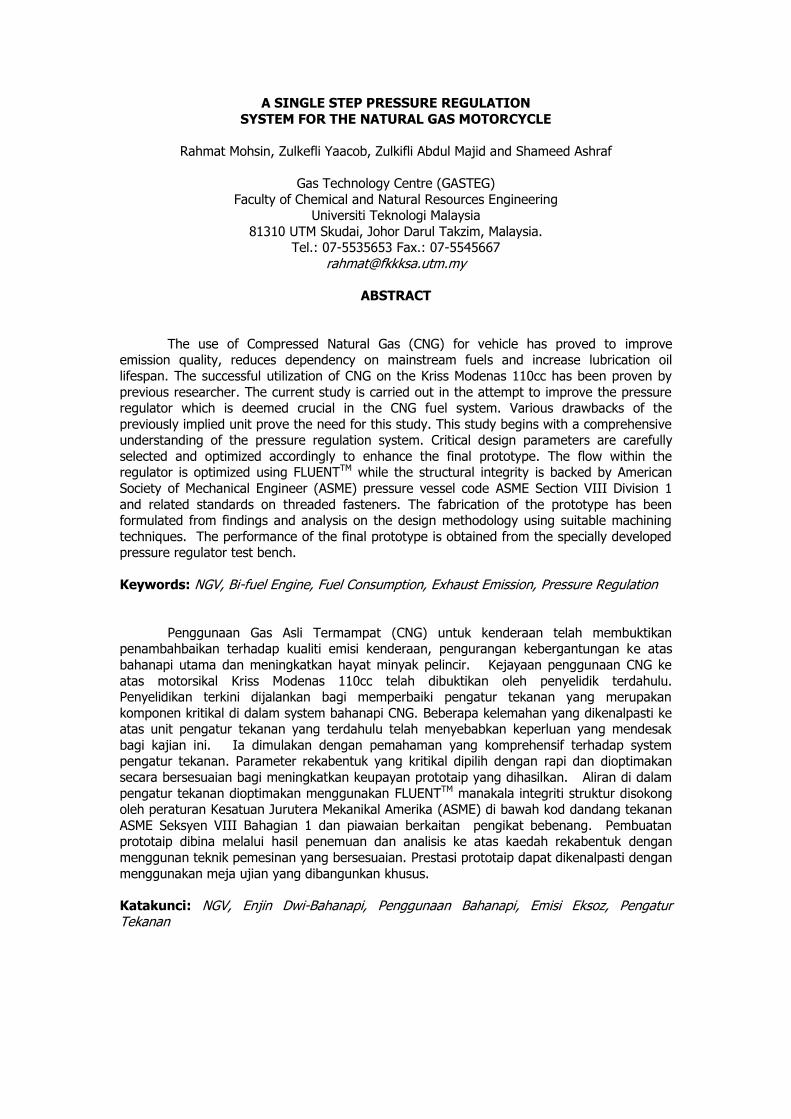
3.1 Pressure Regulator Components
Pressure regulators are produced in many sizes and configurations, but all are bounded
to three basic component categories which are the valve body, the valve trim and the actuator [5]. These components can be further described in terms of elements which are the restricting,
loading and measuring [6]. The loading and measuring element together form the actuating
component of the regulator. The valve trim comprises the restricting element and related linkages that enables the regulator to operate. The restricting element is made up to the valve
seat and valve pad or obturator. Lastly the valve body houses all this components and provides physical support to the components to ensure workability.
The regulator is design to provide constant outlet pressure regardless of the demand
opposed upon it [7]. From the figure below we see that the loading element (spring) exerts force
against the measuring element (diaphragm) which opens the restricting element. When the compartment pressure exceeds the set-point level the measuring element would actuate the
restricting element for full closure. This would cease the natural gas supply into the compartment till the pressure depletes below set-point level. Refer to Figure 2 for basic indication of regulator
components. Supporting components such as support disc, set point screw, vent and so on are
provided to aid the regulation mechanism.
No Component Name No Component Name
1 Spring 2 Diaphragm
3 Obturator 4 Threaded Fastener
5 Regulator Body 6 Support Disk
7 Set Point Screw 8 Bonnet Cover
9 Cap 10 Valve Seat
Figure 2 Spring Loaded Pressure Regulator Components
3.1.1 Material Selection
The material selected for the pressure regulator fabrication is required to handle the typical operating temperature of an NGV regulator which varies from -20°C to 120°C. A non
corrosive metal is preferred as it would suit the operating condition better. The mechanism of the pressure regulator enforces the internal components especially the spring to resist fatigue and
shock loading. Selection of component materials for high temperature or corrosive service is
generally limited to stainless steels or high nickel alloys [8]. The high nickel alloys such as Inconel and the beryllium-copper are about 3 to 4 times the cost of Type 18-8 stainless steel [9].
There are a number of groups or families of stainless steel, each containing a number of specific types and each with its own distinguishing characteristics. These three terms- martensite, ferrite,
and austenite- are also descriptive of the three major families of stainless steels [10].
The martensitic stainless steels are nominally 11-13% chromium, are hardenable by heat
treatment and are exemplified by grade types 410 (S41000) and 420 (S42000). This grade is susceptible to absorption of atomic hydrogen, resulting in hydrogen-assisted cracking and has
poor low-temperature impact resistance. Ferritic Grades class of alloys usually contains 15-18%
chromium. The Ferritic grades, exemplified by S43000 (16-18Cr-0.12C), have corrosion resistance superior to the martensitic grades, primarily by virtue of their higher chromium content. Their
treatment upon these grades has no effect on its hardness. The austenitic group is the most
4
5
6
7
8
9
10
11
1
2
3
important for process industry applications. By virtue of their austenite-forming alloy additions,
notably nickel and manganese, they are not hardenable by heat treatment, but can be strain-hardened by cold-work. The conventional 18-8 austenitic stainless steels are exemplified by Type
304 (S30400). These alloys have rare combination of corrosion resistance, high-temperature strength, and oxidation resistance, ease of fabrication good ductility and good impact resistance
down to at least -183°C (-216°F). Their mechanical properties in general, are excellent.
Heat treatment used upon spring material to improve the material properties is
preferably avoided as it commonly causes spring failure [11]. Without considerable experience in the techniques of heat treatment, therefore, spring materials should always be used „as is‟ [12].
Among the types of stainless steel, the Type (18-8) cannot be heat treated as these alloys do not respond to the hardening and tempering method [13]. At low temperatures the stainless steels of
the 300 series are useful, but those of the 400 series are not [13]. These arguments above prove
that the best common component material that would oblige the design requirement is the stainless steel Type 304 (18-8). This material would be used throughout the design and
fabrication of the pressure regulator due to its advantages over other materials.
3.1.2 Restricting Element The restricting element design is given the prime attention as this would be the
component that would determine the pressure control. The obturator that moves against and
away from the valve seat to prevent and permit the flow of gas to the regulator compartment serves as the restricting element. The limiting factor of flow within this system is the occurrence
of choking. The equation governing the area of the conduit and mass flow is given by oosthuizen and carscallen [14]
12
1
1
2*
OOP
mA
(1)
*A = Critical Area
m = Mass Flow rate
= Specific Heat Ratio
OP = Stagnation Pressure
O = Stagnation Density
From the equation we see that the mass flow rate through the close conduit is proportional to the cross sectional area of flow. The supply of natural gas from the storage tank
is supplied through high pressure tubing, the internal diameter for this commonly used tubing for
CNG supply is 3 mm. The design of a valve seat with an area larger then this value would be unnecessary as choking would have already occurred downstream where the diameter is smaller.
The design of a valve seat smaller diameter would cause further choking and reduce the mass flow into the regulator. For this reason, the valve seat is designed to be 3 mm in diameter.
The movement of the obturator which moves against the valve seat to restrict flow and
moves away to permit flow requires evaluation. How far should the obturator move in order to
provide sufficient natural gas to maintain the desired pressure within the regulator at the regulators full capacity? The complicated geometry of the flow makes manual calculation tedious,
thus requiring the use of Computational Fluid Dynamic Software [15]. The implementation of this
method helps determine the mass flow rate of gas flowing between the valve seat and obturator
at a given opening gap. The simulation is conducted on a compressible, steady state condition with adiabatic wall basis. The fluid is taken as methane due to the nature of Malaysian natural
gas which contains over 93% methane.
3.1.3 Mechanical Linkages
The mechanical linkage relates the restricting element, measuring element and the
loading element to form a working pressure regulation mechanism is shown in Figure 3. The linkage is pivoted to the regulator body at point X shown in the diagram. There are basically
three forces acting on the linkage where the resultant of these forces will determine the actuation of the restricting element. The force denoted as 1 is the force exerted by the fluid
entering the regulator compartment on to the obturator. The magnitude of this force varies due to the depleting storage pressure. As we know, force is pressure acting over a surface area. The
force denoted as 2 is caused by the pre-compression of the spring (Loading element). This
setting cause the compartment pressure to rise, the greater the force the greater the compartment pressure. The force denoted as 3 is the result of the compartment fluid acting upon
the diaphragm which serves as the measuring element. This force restricts the entrance of the gas to the compartment which reduces the compartment pressure. Based on fundamental
calculations on forces and knowing the desired compartment set point pressure and maximum
obturator movement away from the valve seat, a suitable loading element (spring) is designed.
Figure 3 Mechanical Linkages Arrangement
3.1.4 Loading Element
Compression springs made from round wire are the easiest to design and produce. They are accurate, reliable, and tolerable to high stress, have longer fatigue life, and should be used in
preference to any other type [16]. There are basically four types of ends for a fully formed helical compression spring they are plain ends, plain ends ground, closed ends and closed ends ground.
The loading element spring of the pressure regulator will be designed to have the closed ends
ground as it requires accurate precision force requirements and resistance towards buckling.
1
3
2
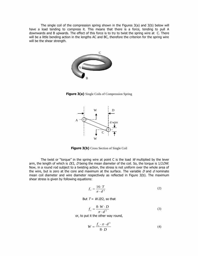
The single coil of the compression spring shown in the Figures 3(a) and 3(b) below will
have a load tending to compress it. This means that there is a force, tending to pull A downwards and B upwards. The effect of this force is to try to twist the spring wire at C. There
will be a little bending action in the lengths AC and BC, therefore the criterion for the spring wire will be the shear strength.
Figure 3(a) Single Coils of Compression Spring
Figure 3(b) Cross Section of Single Coil
The twist or “torque” in the spring wire at point C is the load W multiplied by the lever arm, the length of which is D/2, D being the mean diameter of the coil. So, the torque is 1/2DW.
Now, in a round rod subject to a twisting action, the stress is not uniform over the whole area of the wire, but is zero at the core and maximum at the surface. The variable D and d nominate
mean coil diameter and wire diameter respectively as reflected in Figure 3(b). The maximum
shear stress is given by following equations:
3
16
d
Tf s
(2)
But T = W.D/2, so that
3
8
d
DWf s
(3)
or, to put it the other way round,
D
dfW s
8
3 (4)
d wire
C
A
W
W D
B
A
C
These are the basic equation for load, where the load which a spring can carry is
proportional to the stress, to the cube of the wire diameter, and inversely proportional to the coil diameter. A ten coil spring will carry exactly the same safe load as one with only two if the wire
and coil diameters are the same. The number of coils does have an effect on the spring performance; in many cases the spring deflection under load is almost as important as the load
itself. The corresponding end B of the bottom half coil is thus displaced upwards where as end A
is displaced downwards. The total deflection is 2 δ where δ movement downwards for point A and δ upwards for B. Add another pair of half coils and the next end will move by 4 δ, and so on.
Deflection depends on the number of coils. In spring work, this deflection is usually stated as the Rate of the spring R and in Imperial measure is defined as the load in lbf/in. (in S.I. units this
would be stated, for our size of spring, in Newton/mm). Rate should be determined between 20 and 60 % of total deflection when test lengths are not otherwise established [16]. The deflection
under a given load W is given by the formula below:
4
38
dG
nDW
(5)
nD
dGR
W
3
4
8 (6)
From (3) above you will see that the deflection for a given load depends directly on the size of the load, on the cube of the coil diameter, on the number of coils, and inversely as the fourth
power of the wire diameter. R indicates the spring rate of deflections. And, of course, inversely as the value of torsional modulus of elasticity G, that depends on the material used and on the
temperature of that material, a fact not always remembered when dealing with springs working
at the temperature.
In arriving at expression (1) we assumed that the torque was applied as in the case of a drive shaft. But a coil spring is coiled, the shaft is curved. This makes a big difference, for the
surface stress is no longer uniform around the circumference. It is higher on the inside of the coil
than on the outside. To rectify this condition, the correction factor is introduced. The correction is also needed because the wire is curved where the curvature depends on the ratio of coil
diameter to wire diameter. The correction factor for shear stress is given as K1 where as the correction factor for deflection is given as K2. Adding these values to Equations (2) and (6) we
get Equations (10) and (11).
CC
CK
615.0
44
141
(7)
2
2
22
12
C
CCK
(8)
d
DC (9)
31
8
d
DWKf s
(10)
nD
dGKR
3
4
28
(11)
As we can see the correction factor given above is a function of the spring index. The
ratio of the mean coil diameter D divided by the wire diameter d is called the spring index and is
one of the most important factors in design and manufacture. Low ratios under 4 cannot always be coiled on automatic coilers because the high pressure of the cutoff tool needed to sever the
wire may break the portion of the arbor used as a cutting edge. Low ratios also may cause pretempered wire to crack or may reduce its ability to withstand the deflection desired [17]. High
indexes over 16 and particularly those over 20 causes greater flexibility in the coils and require
tolerance at least 50 percent larger than standard. Higher ratios require modification on the coiling tools and cause difficulty large variations in coil diameter. Indexes 3.5-15 are commercially
practical to manufacture, but indexes in the range of 5.5-9 are preferred, particularly for close tolerance springs and those subjected to cyclic loading [11].
3.1.5 Pressure Regulator Body
There are basically two considerations that are involved in designing a suitable pressure
regulator body. The internal compartment of the regulator body is cylindrical in shape with 60 mm diameter and 28 mm in height. It is fitted with a bonnet cover at the top to ease access to
the internal component. The determination of the minimum wall thickness of this compartment
and the bonnet cover is evaluated based on the ASME Boiler and Pressure Vessel Code Section VIII Division 1. The selection of suitable threaded fastener to hold the bonnet cover in place
against the internal forces is dealt with in the following section. The material used for the development of the body is stainless steel 304 as it complies with the Pressure vessel code and
suits the working condition of the regulator best. The design would cater for the full CNG storage
pressure of 207 bar to provide maximum safety as it is a preliminary design prototype. The bottom wall, cylindrical side wall and the bonnet cover minimal wall thickness are presented in
the final product drawing which is labelled with dimensions.
3.1.6 Threaded Fasteners
One of the distinct advantages of the ISO metric nut strength system is that each
property class of nut was specifically designed, dimensionally and metallurgically, to properly mate with a property class of bolt [19]. Consequently, when the correct class of nut is selected,
even under the most adverse combination of conditions, the bolt will normally break first. This occurrence eases the detection of failures prior to loading. There are just two metric screw
thread forms, the M profile which is the standard for commercial fastener and the MJ which is the
standard for aerospace quality fasteners. The Standard commercial fastener M profile is selected for the current study as it is easily attainable in the market and economically favourable. Based
on SAE J1199, Bolt of class 4.6 having M6 x 1 is selected as it has suitable property to hold the calculated force exerted on to the fastener. The guideline in bolt and nut selection outlines that
the nut selected shall be of a higher class compared to the bolt. Therefore based on ASTM
A356M nut from class 5, M6 x1 Hex style 1 was selected.
3.1.7 Structural Integrity Simulation
The final design of the designed prototype is evaluated in term of its structural integrity using structural software based on finite element called NastranTM. Similar to the approach
implied in the computational fluid dynamic method, the geometry is set using a computer aided
design software called PatranTM.
3.2 Pressure Regulator Test Bench Design and Development
The regulator test rig was designed and built to gauge the performance of NGV pressure regulators. Suitable ports on the regulator were used to place pressure, temperature and flow
measuring devices. The positioning of the sensors at various points of the regulator provides comprehensive understanding of the regulator, especially the ability of the regulator to reduce
pressure and maintain the outlet pressure regardless of the flow demand downstream. Pressure and temperature difference after pressure reduction is logged and analyzed with this test rig for
various outlet flow rates.
This test rig is suitable to be used to test most NGV pressure regulator as they have
similar designs and operating pressure. We could simply remove and install the probes to accommodate any similar type NGV pressure regulator with the help of suitable fittings. The
dynamic performance of pressure regulator coping with fluctuating outlet flow can be used to
select regulators according to the requirement. The general construction of the test rig with component listing is shown in Figure 4.
No. Description No Description
1 Ball Valve 2 Tee joint
3 2 Valve Manifold 4 Pressure Gauge
5 Quick Connect (female) 6 Quick Connect (male)
7 Thermoplastic Hose 8 Needle Valve
9 Check valve 10 1 litre Cylinder
11 Connector 12 Flow meter
Figure 4 Schematic Drawing of the Pressure Regulator Test Rig
Cylinder at
200 Bar
NGV
Pressure
Regulator
2 1
3
4
5 6
7
6
5
8
9
10
10
11
2 4
8
8
12
Power
Supply
PICO
TC-08
PICO
ADC 16
Personal
Computer
4.0 RESULTS AND DISCUSSION
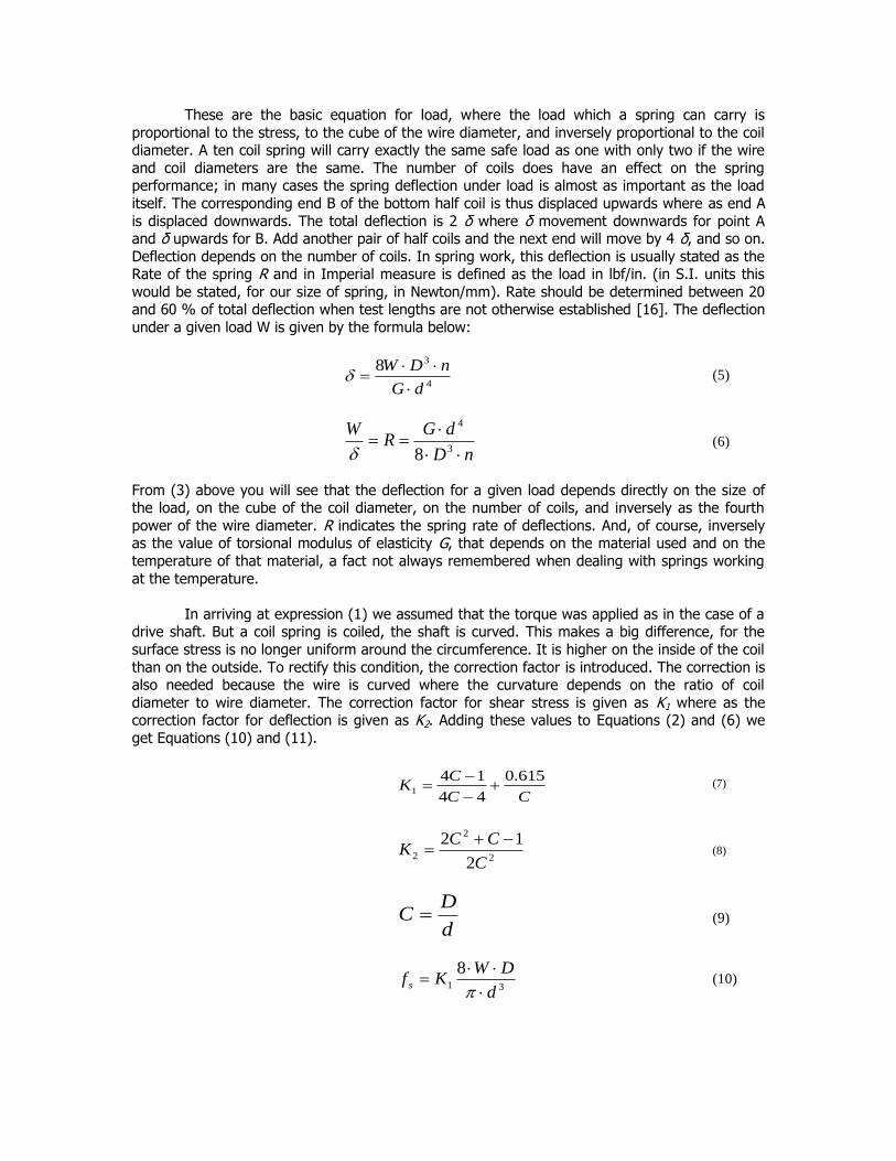
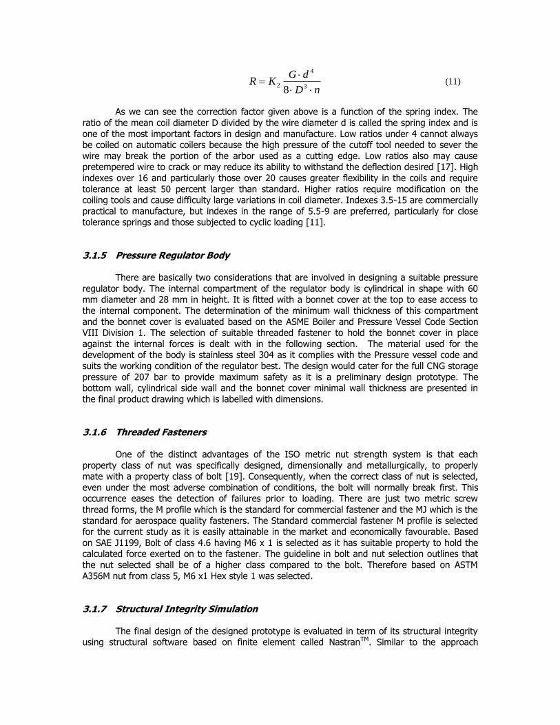
4.1 Computational Fluid Dynamic Analysis
Figures 5, 6 and 7 show results obtained using CFD technique. Various position of the
obturator from the valve seat is simulated using FLUENTTM Computational Fluid Dynamic
Software. The geometry is generated and meshed using GAMBITTM which is a Computer Aided Design Software. The boundary conditions and fluid properties are defined within FLUENTTM and
simulated to obtain the corresponding mass flow rate at different obturator positions away from the valve seat. The following picture shows the results of the simulation that‟s shows properties
of a plane. This method determines the desired opening to provide the mass flow rate that would meet the need of the natural gas motorcycle. The study moves on the design of the mechanical
linkage.
Figure 5 CFD Structural Meshing
Figure 6 Contours of Thermal Conductivity
Inlet
Outlet
Restriction
Obturator
Figure 7 Contours of Velocity Magnitude
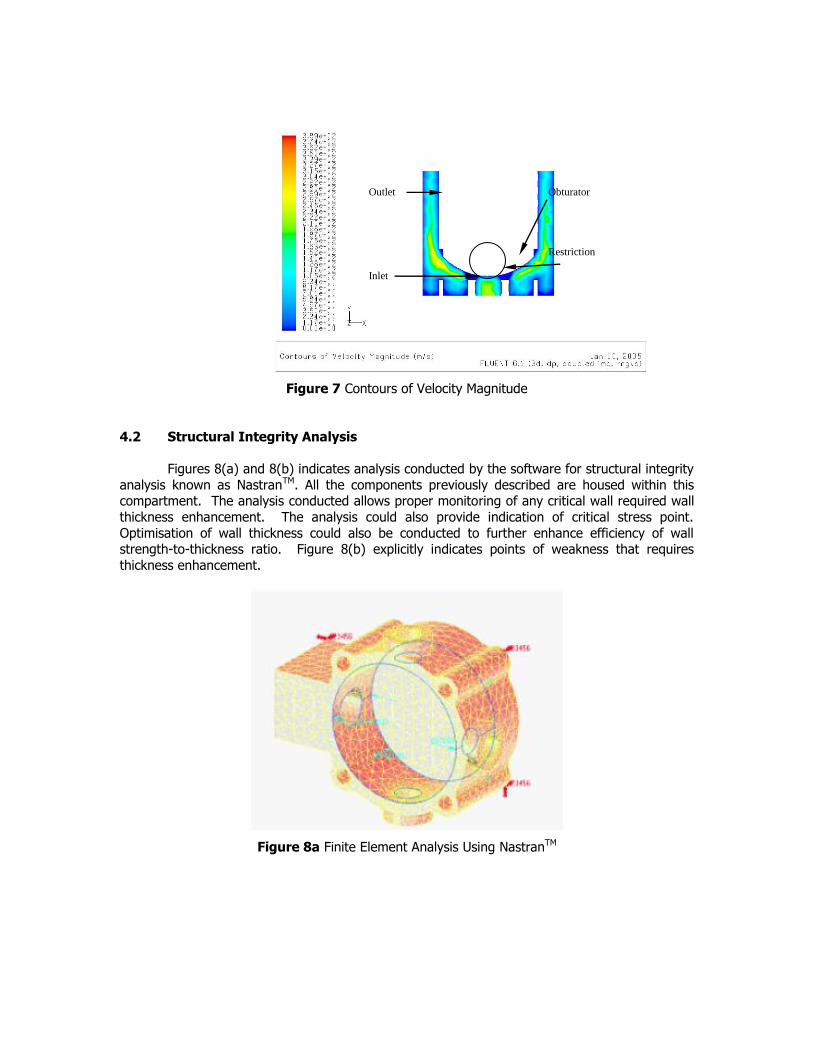
4.2 Structural Integrity Analysis
Figures 8(a) and 8(b) indicates analysis conducted by the software for structural integrity
analysis known as NastranTM. All the components previously described are housed within this compartment. The analysis conducted allows proper monitoring of any critical wall required wall
thickness enhancement. The analysis could also provide indication of critical stress point.
Optimisation of wall thickness could also be conducted to further enhance efficiency of wall strength-to-thickness ratio. Figure 8(b) explicitly indicates points of weakness that requires
thickness enhancement.
Figure 8a Finite Element Analysis Using NastranTM
Inlet
Outlet
Restriction
Obturator
Figure 8b Weak Area Identification Using Finite Element Analysis Using NastranTM
4.3 Component Selection and Assembly
The pressure regulator test bench comprises of a compilation of equipment assembled at a desired orientation to work as desired. It is specially fabricated to provide encouraging working
space to conduct test on the regulator. The bench is capable of holding all the related apparatus in place. The storage cylinder containing high pressure test gas is placed at the top of the bench.
This eases maintenance such as charging of gas, leaks checks and enables gas to disperse to the
surrounding in case of leak.
Pressure sensors selected have measurable pressure range of 250 bar down to 0, while
thermocouples are picked to suit the typical NGV pressure regulator temperature range of -20°C to 120°C. Previous test conducted on the first generation fuel system proved a maximum
consumption of 24 liters per minute of natural gas at full throttle. Thus, a slightly higher range of flow meter is selected with a capability to operate from 0 to 30 liters per minute. Suitable
adapters and power supply units are selected respectively to cater for the equipments. The thermocouple is operated with the Pico TC-08 is connected to the personal computer for data
logging. Both the signals from the pressure sensors and the flow meter are processed by the Pico
ADC-16 powered by the personnel computer. Pico logging software provided with both the TC-08 and ADC-16 is used to provide real time data.
Gas is transferred from the bulk storage to the storage cylinder onboard the test bench
through various valves and fittings. The high pressure solenoid valve attached to the regulator is
held shut in the absence of electric current usually supplied when the vehicle is switched on. The power supply onboard the test bench provides electric current at suitable volts to the solenoid
coil to enable the High Pressure Solenoid Valve to open allowing natural gas to enter the first stage of pressure reduction.
Pressure and temperature sensing are done before and after the pressure regulating stage. These pressure and temperature sensors will help analyze the conditions within the
regulator during operation. The outlet of the regulator is equipped with a flow meter and a pressure sensor to analyze the effects of various flow obtained with a help of variable valve. The
natural gas is supplied to the motorcycle or any vehicle under test.
5.0 CONCLUSION
Research conducted has lead to the production of a single step NGVM pressure regulator
prototype. Analysis conducted using numerical approach has enable researcher to optimise its design in terms of body strength and viable wall thickness. This analysis allows modification
made to the theoretical body structure of the pressure regulator prior to the production of the
original prototype.
ACKNOWLEDGEMENTS
Authors wishes to extend gratitude to the Ministry of Science Technology and Innovation
(MOSTI) for the financial support under Vot 74169. Special thanks dedicated to the Research
Management Center (RMC), UTM for continual support and assistance during the tenure of research. To those involved directly and indirectly to this project, authors are deeply indebted.
NOMENCLATURE:
δ = deflection, mm (inches)
n = number of active coils G = Torsional modulus of elasticity, N/m2 (lbf/sq.in)
R= spring rate, N/mm of deflection (lbf/in) fs = max. shear stress, N/m2 (lbf/sq.in)
T = Torque, N/m (lbf/in)
W = Load, N (lbf) d = Wire diameter, mm (in)
D = Mean coil diameter, mm (in)
= 22/7 (a constant)
REFERENCES:
[1] Yaacob, Z., Majid, Z. A., Martin, P. K. P. (2000). Natural Gas Motorcycle for Cleaner Cities.
Regional Conference on Energy and Environment, 15-16 Feb. 2000. Kuala Lumpur. A2-1-7. [2] Yaacob, Z., Majid, Z. A., Martin, P. K. P. (1999). A Study on Exhaust Emission, Performance
and Lubricating Oil. Jordan International Chemical Engineering Conference III. 27-29 Sept. 1999. Amman. Jordan, 125-140.
[3] Majid, Z.A., Yaacob, Z., Martin, P. K. P. (2000). Natural Gas Motorcycle-Emission.
International Conference & Exhibition on Natural Gas Vehicle. 17-20 Oct. 2000. Yokohama. Japan, 413-420.
[4] Heenan, J. S. 1996. Fuel System Pressure Control Improves NGV Performance. SAE Technical Paper 960851.
[5] Whitehouse, R.C. 1993. The Valve and Actuator User‟s Manual. The British Valve and
Actuator Manufacturers Association. USA: Mechanical Engineering Publications Limited. [6] Floyd, D, J. 1972. Fundamental of Gas Pressure Regulation. Technical Monograph 27.
Fisher Controls Company. Iowa, USA: Fisher Control Company. [7] Floyd, D, J. 1973. Fundamental of Three-Mode Controllers. Technical Monograph 28. Iowa,
USA: Fisher Control Company. [8] Stanton, V. A. 1961. The Best Spring Material for High Temperature. Spring Design and
Application. Louisiana, USA: McGraw-Hill.
[9] Beckwith, J. B. 1961. Flat Spring Material Cost and Stress Factors. Spring Design and Application. Louisiana, USA: McGraw-Hill.
[10] Dillon, C. P. 1995. Corrosion Resistance of Stainless Steels. Maryland: Marcel Dekker Inc.
[11] SAE HS 795., 1990, Manual on Design and Application of Helical and Spiral Springs. [12] Warring, R.H. 1973. Spring Design and Calculation. U.K.: Model & Allied Publications
Limited. [13] Carlson, H. 1980. Springs: Troubleshooting and Failure Analysis. New York, USA: Marcel
[15] Versteeg, H. K., W., Malalasekera. 1995. An Introduction to Computational Fluid Dynamics. The Finite Volume Method. Maryland, USA: Prentice Hall.
[16] Cain, T. 1988. Spring Design & Manufacture. Workshop Practice Series Number 19. NewYork, USA: Argus Books Limited.
[17] Eakin, C. T. 1961. High Temperature Creep of coil Springs. Spring Design and Application.
Michigan, USA: McGraw-Hill. [18] Carlson, C. R. H. 1961. Properties of Spring Materials and Allowable Working Stresses.
Spring Design and Application. Pennsylvania, USA: McGraw-Hill. [19] Blake, A. 1986. Threaded Fasteners. What Ever Engineer Should Know Series Vol. 18. USA:
Marcel Dekker Inc.
[20] Dillon, C. P. 1995. Corrosion Resistance of Stainless Steels. Marcel Dekker Inc. [21] NFPA 52-1984., 1984, Standard for Compressed Natural Gas (CNG) Vehicular Fuel Systems.