1 Prototyping the campus network Designing and Supporting Computer Networks – Chapter 7 Copyleft 2012 Vincenzo Bruno (www.vincenzobruno.it) Released under Creative Commons License 3.0 By-Sa Cisco name, logo and materials are Copyright Cisco Systems Inc.
Transcript
1
Prototyping the campus network
Designing and Supporting Computer Networks – Chapter 7
Copyleft 2012 Vincenzo Bruno (www.vincenzobruno.it)Released under Creative Commons License 3.0 By-SaCisco name, logo and materials are Copyright Cisco Systems Inc.
Overview
Prototypes and Pilots● The testing phase provides an opportunity to identify parts of the
design that do not operate appropriately and redesign them.
● The proposed stadium network has many design changes. Therefore, the NetworkingCompany designer tests the function of critical areas of the design before creating the final proposal.
● There are two common methods used to test a network design:
When to Create a Pilot?
● Many functions of the proposed network can be tested using prototypes. However, using a pilot is a good option in the following circumstances:
● When the prototype is not big enough to test functionality - Testing the operation of a routing protocol in a network with one hundred routers may not be feasible in a prototype.
● When the performance of the network is dependent on the operation of a specific device or third-party technology - An example is an expensive video scoreboard or a third-party provided WAN link.
● The only major design change that requires a pilot is the installation of the Frame Relay connection to the remote sites.
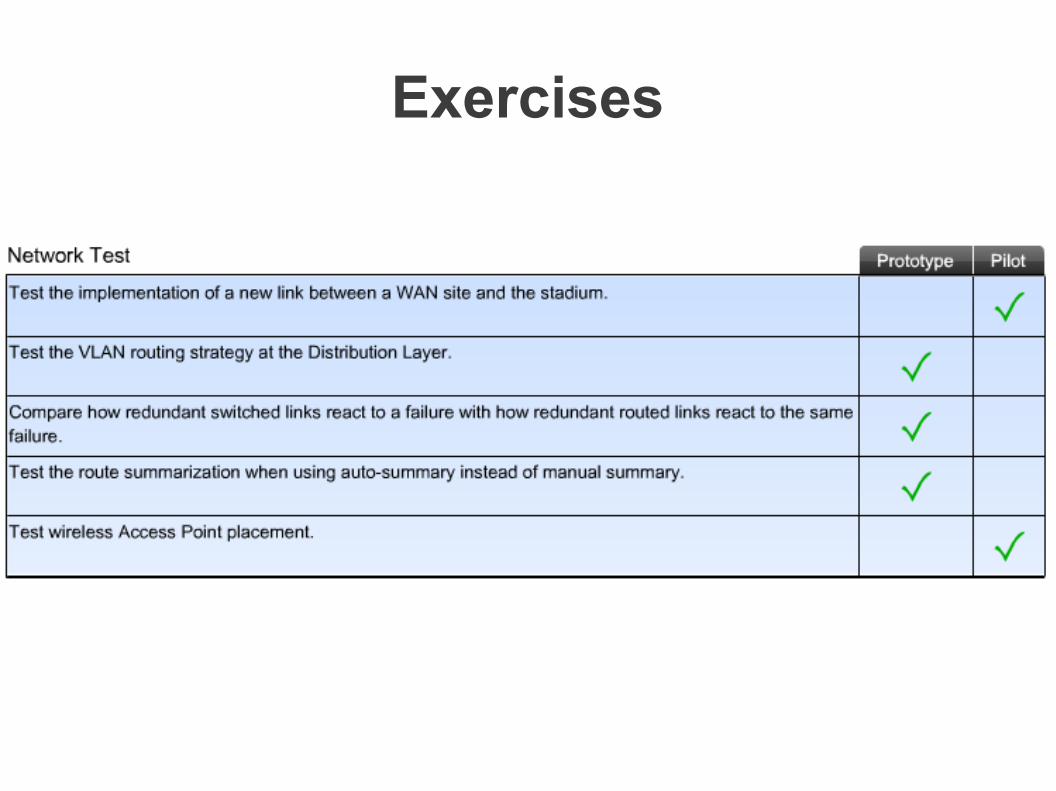
Exercises
Prototype test plan document
Prototype example (1)
The purpose of this prototype is to demonstrate how the individual access layer VLANs can be configured to separate traffic from the end-devices, IP telephones, and video cameras.
The intent is to demonstrate that computers on VLAN 2 cannot access devices on the voice or video VLANs unless expressly granted permission.
Test 1: Baseline Connectivity Test Verify physical and IP connectivity between devices on the prototype network.Collect operational baselines.Demonstrate IP connectivity between devices on the same VLANs.Demonstrate lack of IP connectivity between devices on different VLANs.
Test 2: VLAN Routing Test Demonstrate routing of traffic between separate VLANs, unrestricted.Demonstrate routing of traffic between separate VLANs with restrictions.Simulate traffic and compare to baselines.
Prototype example (2)
Design and Topology Diagram
Prototype example (3)
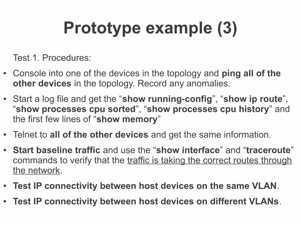
Test 1. Procedures:
● Console into one of the devices in the topology and ping all of the other devices in the topology. Record any anomalies.
● Start a log file and get the “show running-config”, “show ip route”, “show processes cpu sorted”, “show processes cpu history” and the first few lines of “show memory”
● Telnet to all of the other devices and get the same information.
● Start baseline traffic and use the “show interface” and “traceroute” commands to verify that the traffic is taking the correct routes through the network.
● Test IP connectivity between host devices on the same VLAN.
● Test IP connectivity between host devices on different VLANs.
Benefits and procedures of Prototyping
● Benefits:
● It demonstrates to both the customer and the network designer that the network design meets the business goals and technical requirements.
● It creates an opportunity to compare different design options to see which one performs best.
● Pocedures
● Before beginning tests to verify specific design functionality, the NetworkingCompany staff builds and verifies the prototype network in the test plan.
● The designer then works with the NetworkingCompany staff to set up and perform the test plan.
● They discuss the methods for measuring the prototype network functions under different conditions.
Verifying the design meets goals
● One of the technical requirements supporting business goals is the integration of the security camera surveillance video network into the stadium LAN.
● To demonstrate this functionality, it must be possible to view the surveillance video from a PC located on a different segment of the network and only the authorized stations can view it.
● The designer lists what must occur to accomplish this goal:
● Create Access Layer VLANs to isolate the surveillance video from the rest of the network traffic.
● Implement an IP address structure that supports the video network VLANs.
● Trunk the VLANs to the Distribution Layer devices.
● Feed the video streams to the video surveillance server.
● Configure ACLs so that the security video can be viewed from other areas of the stadium by authorized personnel, but not by guest users.
● Implement an authentication mechanism on the video surveillance server to ensure that only the authorized users have access to the security videos.
Tools used to validate network design
Test redundancy and resiliency
● The stadium network has two types of redundant links between devices: Layer 2 uplinks and equal cost Layer 3 links.
● To test the two types of links, the designer and the NetworkingCompany staff introduce link failures into the topology.
● By observing the amount of disruption in network service, they can determine how long it takes for the network to resume normal functionality.
Identify risks and weaknesses
Creating the Test Plan● The designer needs to demonstrate functionality of the
converged network combining data, IP telephony, and video surveillance traffic. To do this, the designer must decide:
● What types of tests to run
● How much of the network must be built to perform the tests
● How to determine the success or failure of the test
● The designer lists the test outcomes that indicate that the goal of a converged network can be met.
● The main focus of the test is to show how the new network serves the main business goal.
● The NetworkingCompany staff tests the individual technical requirements to determine if the network design addresses each goal.
● They repeat this process for each of the high-priority goals.
Testing the Routing Protocol
● To demonstrate how well a routing protocol converges in the event of a link failure is difficult to do with a prototype network, and is risky to attempt in a pilot network.
● In a pilot, a single routing protocol misconfiguration can disrupt the entire network.
● Because of this risk, the designer decides to use the simulator for the routing protocol tests.
● The designer wants to compare the use of static routes for the redundant links to the use of the EIGRP routing protocol.
● The test plan outlines a test of static routes first, then the configuration of EIGRP, so that a comparison can be made.
Testing the Routing Protocol
IP addressing scheme
● The network designer recommends a simulation tool to test the IP addressing scheme.
● Using the simulation tool, the designer can determine if the addressing structure enables summarization and can support the necessary scalability.
● The designer configures the simulated network with the same number of networking devices as the planned network.
● The designer then validates the placement of the various subnets and the configuration of the route summarization.
Server Relocation for the Stadium Network
● One of the business goals of the stadium network is to provide better customer service. This goal can be achieved by improving access to the website for viewing schedules, purchasing and printing tickets, and purchasing merchandise.
● The proposed design recommends relocating the web server, DNS server, and database server to a server farm located in a new data center.
● Relocating the servers from the stadium management offices to a new data center is a major change in the way the traffic flows in the stadium network.
● The requirements for nearly 100% uptime and availability can be better accomplished if the servers are located in a central data center.
● The data center design is a network module that can be tested in a prototype.
What needs to be tested in the prototype?
● In the proposed network design for the stadium, the following elements directly impact the server farm:
● Creation of modular server farm topology
● Implementation of redundant links for server connectivity
● Location of redundant Layer 2 switches for server connectivity
● Use of a per-VLAN rapid spanning tree to shorten the time for redundant switched links to become active after a failure
● Configuration of a flexible IP addressing structure
● Configuration of EIGRP in the data center Core and Distribution Layers
● Configuration of strict traffic filtering policies to prevent unauthorized access
Prototype scheme
Baseline Measurements
● It is important to develop the baseline measurements of the prototype network.
● From the results observed during the various tests the staff can identify and record any processes or functions that increase processor usage or decrease available bandwidth.
● To simulate traffic on the network, the designer recommends running a traffic generator on one of the attached PCs.
● A traffic generator is a testing tool that simulates various levels of network use.
● In the case of the server farm prototype, the designer intends to use the tool to simulate network traffic to the web server.
● Useful tool: http://jmeter.apache.org/
Per VLAN Rapid Spanning Tree Plus
● RSTP provides rapid connectivity following the failure of a switch, a switch port, or a LAN.
● RSTP enables switch port configuration so that the ports can transition to forwarding directly when the switch reinitializes.
● The RSTP (802.1w) standard assumes only one spanning-tree instance for the entire switched network. This is regardless of the number of VLANs.
● The Cisco implementation of RSTP is Per VLAN Rapid Spanning Tree Plus (PVRST+).
● PVRST+ defines a Spanning Tree Protocol that has one instance of RSTP per VLAN. Cisco documentation often refers to this implementation as RSTP.
PVRST+ example
RSTP port roles● Root- A forwarding port elected for every non-root switch that
gives the least-cost path to the root switch.
● Designated- A forwarding port elected for every switched LAN segment based on the best bridge protocol data unit (BPDU). This port is the least-cost path to the root switch from the LAN segment.
● Alternate- An alternate path to the root switch for a non-root switch that is different from the path that the root port takes. This port is blocked for forwarding traffic.
● Backup- A backup path that provides a redundant, but less desirable, connection to a segment to which another port on the non-root switch already connects. This port is blocked. (Backup ports can only exist where two ports are connected together in a loopback by a point-to-point link or bridge with two or more connections to a shared LAN segment.)
● Disabled- A port that has no role within the operation of spanning tree.
RSTP in the Stadium Network
Validating the security plan
● Availability Requirements
● The network designer addresses availability requirements by using redundant links and components where possible. Configuring RSTP for Layer 2 and using EIGRP for Layer 3 ensures quick convergence of the network in the event of a failure.
● Multilayer Security
● At the Access Layer, employing port security and disabling unused ports help prevent the network from unauthorized access.
● ACLs filter traffic and prevent spoofed, or un-requested, traffic from reaching the servers. The ACLs are placed at the point where the server farm connects into the stadium network.
● Firewalls
● Firewalls and firewall feature sets in the Cisco IOS Software provide stateful firewall capability.
● IPSs protect the network from known threats and abnormal traffic patterns.
Testing the ACL Design
● The network designer decides to test the ACL design and placement because it has the most potential for variability.
● The designer creates a test plan that lists all of the filtering rules and methods for testing.
● The designer suggests using a network simulator, rather than a prototype network.
● The simulator can be configured quickly to contain all of the proposed devices and links.
Eliminating Weaknesses
● Identified Weakness
● The tests show that the ACLs at the Distribution Layer prevent unauthorized traffic from entering the server farm but are not effective at filtering the traffic within the VLANs themselves. The test traffic between servers in the same VLAN is not restricted.
● Recommendations
● The designer recommends that the stadium management consider using multilayer switches at the Access Layer.
● Multilayer switches provide more flexibility than Layer 2 switches in separating and filtering traffic from devices within the data center itself.