In-line Circulators file no: 10.10 date: april 2018 supersedes: 10.10 date: december 2017 solution outline proven reliability category leading value S&H Series ecm motors available for reduced energy consumption Permanently lubricated, maintenance–free models Easily serviceable for lowest life cost Fits existing pipe connections
Transcript
In-lineCirculators
f ile no: 10 .10date: april 2018
supersedes: 10 .10date: december 2017
s o l u t i o n o u t l i n e
tm
proven reliability category leading value
S&H Series
ecm motors available for reduced energy consumption
Permanently lubricated, maintenance–free models
Easily serviceable for lowest life cost
Fits existing pipe connections
no oilingMaintenance–free design* uses permanently lubricated ball bearings.* All models except (6 series) s–69, h–63, h–64, h–65, h–66, h–67, h–68
long seal lifeepdm mechanical seal made from long–lasting Sintered silicon carbide to withstand high temperatures.
low part inventoryModular 3–piece design includes a universal shaft and bearing module that fits 12 models (s–25 to s–57 and h–32 to h–54).
reliability Modular design supports a wide range of motor options.
lasts for lifeof installation Easy to repair and rebuild.
traditional s&h with more value added
* Certified ≤0.25 weighted average percent lead and complies with California Health and Safety Code Section 116875 (commonly known as ab1953).
materials of construction
Notes:1 All circulators are to be mounted with motor and shaft in
horizontal position.2 For domestic hot water or fresh water systems, always specify
lead free bronze body pumps. 3 Permanently lubricated, maintenance–free s&h circulators are
armstrong Series s&h in-line circulators are ideal for applications
such as hydronic heating and cooling, domestic water systems, multi-stage zoning and general industrial service.Armstrong 3-piece circulators use a proven design that continues to evolve. The expanded temperature range makes them suitable for more applications, and the industry-accepted flange configuration makes s&h circulators a perfect solution when you need to change out pumps quickly without the need for pipe modifications.
armstrong Series s&h in-line circulators are ideal for applications
such as hydronic heating and cooling, domestic water systems, multi-stage zoning and general industrial service.Armstrong 3-piece circulators use a proven design that continues to evolve. The industry-accepted flange configuration makes s&h circulators a perfect solution when you need to change out pumps quickly without the need for pipe modifications.
when provided with single phase
115 v K hp O hp
230 v K hp O hp 1 hp
Ecm (electronically commutated motor) technology offers important
energy savings over traditional designs of electric motors. Circulators using ecm technology can be as much as 20% more efficient.
Armstrong offers ecm technology as an option for a range of s&h circulators, including s–55 to s–69 and h–53 to h–67.
volts dc
spee
d
0
100%
1 2 3 4 5 6 7 8 9 10
3
2
1
pump max. curve1pump starts from min. curve2pump o�3
0–10v dc control response curve
key ecm benefits
save energy and the planetideal for energy upgrade
1 Pump max. curve2 Pump starts from min. curve3 Pump off
* Gold pump casing shown for potable water applications.
** Red pump casing shown for hvac applications.
for lowestlifetime cost
save energy
0-10v dc control saves up to 80% energy and 6% boiler gas consumption and reduce equipment or pipe wear and tear.
Instant efficiency savings – up to 20%.
Additional energy savings where system allows for manual speed reduction.
Accepts external control for optimized system performance where required.
Application flexibility as seen in the colour schemes for potable water* or hvac** systems.
12
4
3
preferred selection area
Based on 1800 rpm, 60 Hz motors. For 50 Hz motors write for special capacity charts.
head
– f
eet
head
– m
etre
s
0 0.63 1.89 3.15 4.41 5.68 6.94 8.20 9.46 10.73
0 10 30 50 70 90 110 130 150 1700
5
10
15
20
25
30
35
40
0
1.5
3.0
4.6
6.1
7.6
9.1
10.7
12.1
S25
S45
S35
S55
S46
S69
S57
flow – usgpm
flow – l/s
Based on 1800 rpm, 60 Hz motors. For 50 Hz motors write for special capacity charts.
flow – usgpm
flow – l/s
head
– f
eet
head
– m
etre
s
0 0.63 1.89 3.15 4.41 5.68 6.94 8.20 9.46 10.73
0 10 30 50 70 90 110 130 150 1700
10
20
30
50
40
0
3.0
6.1
9.1
15.2
12.1H68
H67
H41
H66H54
H52
H53
H65
H64
H63
H51
H32
preferred selection area
composite peformance charts
H Series
S Series
S Series with ECM Motors
H Series with ECM Motors
head
– f
eet
flow – usgpm
00
10
20
30
40
50
60
20 40 60 80 100 120 140 160 180 200
default settings
S55S57
S69
Note: The max range of the s&h with ecm is the same as that of the current s&h series, however the ecm technology provides full coverage over the entire circulator range that can be manually / externally controlled.
head
– f
eet
H63
H64H65
00
10
20
30
40
50
60
20 40 60 80 100 120 140 160 180 200
flow – usgpm
default settings
head
– f
eet
H53 H54
H66
H67
00
10
20
30
40
50
60
20 40 60 80 100 120 140 160 180 200
flow – usgpm
default settings
h-ecm performance curve – high head pressureh-ecm performance curve – high flow
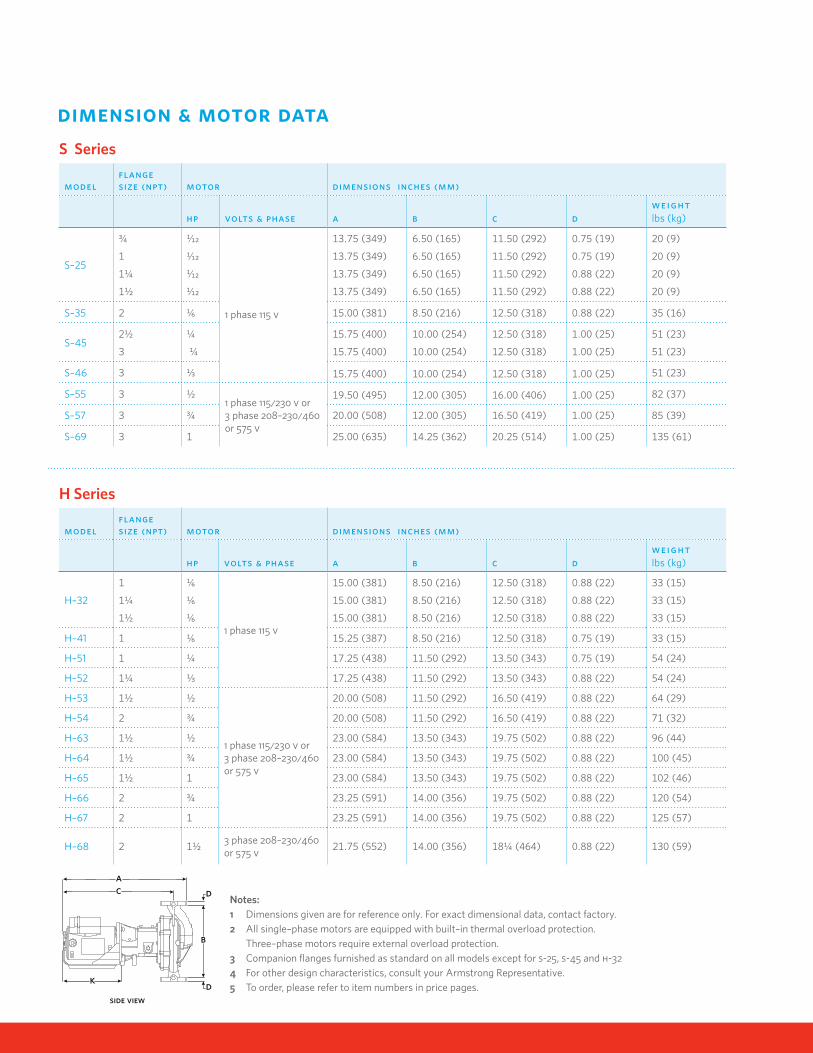
dimension & motor data
modelflangesize (npt) motor dimensions inches (mm)
H–68 2 1½3 phase 208–230/460 or 575 v 21.75 (552) 14.00 (356) 18¼ (464) 0.88 (22) 130 (59)
Notes:1 Dimensions given are for reference only. For exact dimensional data, contact factory. 2 All single–phase motors are equipped with built–in thermal overload protection. Three–phase motors require external overload protection.3 Companion flanges furnished as standard on all models except for s-25, s-45 and h-324 For other design characteristics, consult your Armstrong Representative.5 To order, please refer to item numbers in price pages.
side view
d
d
b
k
ca
H Series
S Series
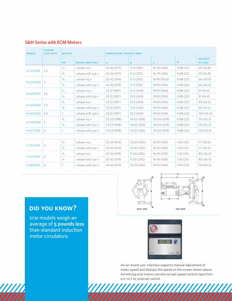
modelflangesize (npt) motor dimensions inches (mm)
An on–board user interface supports manual adjustment of motor speed and displays the speed on the screen shown above.Armstrong ecm motors can also accept speed control input from a 0–10 v dc external control.
S&H Series with ECM Motors
ca
d
b
d
k
side view
d
b
dback view
ecm models weigh an average of 5 pounds less than standard induction motor circulators.
did you know?
tm
a r m s t r o n g f lu i d t ec h n o lo g y. co ma r m s t r o n g f lu i d t ec h n o lo g y established 1934