Page 1
1
Providing Transient Stability by Excitation System Response Improvement
Methods through Long Term Contracts
Ali Khandani1, Tel: (+98)-(918)-(3167748), Fax: (+98)-(23)-(33654089), E-mail: [email protected]
Asghar Akbari Foroud2, Tel (+98)-(912)-(4618433), Fax: (+98)-(23)-(33654089), E-mail: [email protected]
1, 2 Faculty of Electrical and Computer Engineering, Semnan University, Semnan, Iran
Abstract: Maintaining network stability and encouraging generation companies to involve in stability maintaining are 1
major concerns of independent system operator (ISO) in deregulated power system. Excitation system of synchronous 2
generators is effective and well-known equipment which has a significant effect on network stability. Therefore, 3
improving performance of this system can enhance network stability. But utilizing of the methods, which improve 4
performance of excitation system, imposes cost on generation companies. This paper proposes a motivation mechanism 5
for enhancing transient stability which encourages generation companies to improve performance of excitation system. 6
In this mechanism beside excitation system response improving methods, a transient stability constrained optimal power 7
flow is solved in order to ensure maintaining transient stability in different contingencies. A 4-buses test system, the 8
IEEE 14-buses test system, and the IEEE 118-buses test system are used to illustrate effectiveness of the proposed 9
mechanism. Implementation results show that the proposed mechanism not only provides required transient stability 10
margin with minimum operation cost, but also does not restrict generators production capability. 11
Keywords- excitation systems; transient stability; Single Machine Equivalent (SIME); Transient Stability Constrained 12
Optimal Power Flow (TSC-OPF). 13
14
1. Introduction 15
Transient stability is the ability of power systems to maintain synchronism in the event of large disturbances. Such 16
disturbances can increase generators rotor angle deviation; so if corrective actions fail, synchronization with the network will be 17
lost [1]. Excitation system of synchronous generators is effective for primary control action which maintains transient stability 18
of power systems. Excitation system supplies required field current to maintain generator synchronization with the network. 19
Quick excitation system response can increase synchronization torque of generator in order to maintain synchronism with the 20
network. As a result, response rate of excitation system has a significant effect on network stability. Various parameters affect 21
performance of the excitation system. These parameters include ceiling voltage, ceiling current, nominal response of the system, 22
Page 2
2
voltage excitation system response time and etc. Numerous methods were proposed to modify these parameters for improving 23
performance of the excitation system which can be divided into three general categories: (1) expansion capability of excitation 24
system, (2) improvement response of controller, and (3) modification input signal of controller. Over excitation limit exceeding, 25
generator capability curve (GCC) expansion, control response improvement, and high side voltage control (HSVC) are some of 26
these methods. These methods are called briefly improving methods in this paper. Simple implementation and operation, non-27
restriction of generators production capability and good performance are some features of the improving methods. While, 28
installation and operation cost of the improving methods discourage generation companies (GenCos) from utilizing these 29
methods. If GenCos do not utilize the improving methods, other preventive control actions would be used to enhance network 30
stability. 31
Change in generators operation points is one of the preventive control actions for providing network stability. In this 32
method, operation points of generators are modified to make system stable in probably disturbances. Transient stability 33
constrained optimal power flow (TSC-OPF) is a preventive control action which is utilized to optimize operation point of 34
generators in order to provide transient stability of the system. This topic is discussed in several articles [2-6]. In [2-4] rotor 35
angle equations are considered as transient stability constraint in optimal power flow. As rotor angle equations are differential 36
equations, these equations are converted into algebraic set of equations to solve TSC-OPF as a standard nonlinear optimization. 37
Researchers in this field focus on converting differential equations and solving standard TSC-OPF. In [2] authors convert the 38
differential equations into numerical equivalent algebraic equations and use standard nonlinear programming technique for 39
solving TSC-OPF. In [3] authors proposed an enhanced discretization method to reduce converted system dimension and 40
improve computational efficiency of the optimization algorithm. In [4] authors modelled transient stability as an objective 41
function beside active power cost then solved this multi objective optimization by non-dominated sorting genetic algorithm II 42
(NSGA-II). In [5-6] time domain simulation is performed to analyse transient stability of the system and simulation results are 43
utilized in optimal power flow. In [5] simulation results determine critical and non-critical generators of the system. Critical 44
generators are the generators which loss synchronism in the event of contingency. In that method, active powers of the critical 45
generators are decreased to enhance the transient stability of the system. In [6] results of time domain simulation is converted to 46
a single equation as transient stability constraint in OPF. Active power of generators, machine angle, magnitude and angle of 47
buses voltage and other optimization variables are used to determine initial operation point to increase transient stability of the 48
system. In that paper initial operation point is changed to satisfy transient stability constraint. Also some new methods based on 49
modern heuristic methods were used to solve TSC-OPF [7]. In [7] authors proposed a method to estimate critical clearing time 50
(CCT) by dual-kriging method. Result of this estimation is included in a single transient stability constraint of the TSC-OPF. 51
Therefore differential algebraic equations are excluded from TSC-OPF and standard optimization method is used to solve 52
problem. Authors in [8] reviewed different TSC-OPF methods and implemented some of these methods. Also merits and 53
demerits of the studied methods in compare to each other are investigated in [8]. But it should be considered that all above 54
Page 3
3
mentioned TSC-OPF methods cause to increase operation cost of the system, because active power outputs of generators are 55
rescheduled in order to increase transient stability of the system. Moreover, restriction of active and reactive power generation 56
due to changing of the generators operation points is the other disadvantage of those methods. 57
As described utilizing excitation system response improving methods imposes costs on GenCos which discourage them 58
from utilizing these methods. On the other side, other preventive methods for transient stability providing such as TSC-OPF 59
cause to increase system operation cost and also restrict generators capacity. So, this paper proposes a motivation mechanism to 60
encourage GenCos to utilize the improving methods. Transient stability enhancement by utilizing the improving methods does 61
not change optimal operation point of the system in which system operation cost is minimal. If the desired transient stability 62
margin is not provided only by utilizing the improving methods, then change in generators operation points is used to provide 63
more needed stability margin. In this paper, TSC-OPF is used beside the improving methods to minimize the cost of active 64
power rescheduling and provide the desired transient stability of the system. Innovations and contributions of this paper are 65
summarized as follows: 66
1) The proposed mechanism maximizes transient stability and minimizes operation cost of the system by considering 67
effects of the improving methods on network stability. 68
2) This mechanism provides required motivation for GenCos to utilize the improving methods. 69
3) In this mechanism, GenCos capacity for power generating is not restricted. 70
4) In this mechanism, operation point of the system for transient stability providing is the same operation point which 71
minimizes network operation cost. 72
5) In this mechanism, both of the improving methods and TSC-OPF are considered for providing transient stability. 73
The rest of the paper is organized as follows. The second section describes the improving methods for excitation system 74
response. The third section introduces the methodology used in transient stability analysis. The transient stability providing 75
mechanism is presented in section 4. Section 5 is devoted to case study and section 6 concludes this paper. 76
77
2. Improving methods for excitation system response 78
Performance of excitation system affects stability of the system. Results of previous researches show that the fast 79
response AVR and high ceiling voltage exciter significantly reduce first rotor angle swing of generators in the event of 80
contingency [9]. Excitation system response depends on the controller and limitation of the excitation system. Therefore in this 81
section, four methods that affect the excitation system response are described. Over excitation limit exceeding and generator 82
capability curve (GCC) expansion enlarge capability of the excitation system and cause to increase ceiling voltage of the 83
exciter. Controller response improvement and high side voltage control (HSVC) enhance control performance of excitation 84
system and cause to reduce response time of the control system. 85
86
Page 4
4
2.1. Over Excitation Limit Exceeding 87
Active and reactive power generation limits of the synchronous generator are defined by its capability curve. Capability 88
of generating reactive power is usually limited by field winding current. Over excitation limit is the upper limit of capability 89
curve that restricts reactive power generation. This limit protects generator rotor winding from over current in steady state 90
operation. IEEE/ANSI C50.13 is an operational standard for exceeding of over excitation limit [10]. According to this standard, 91
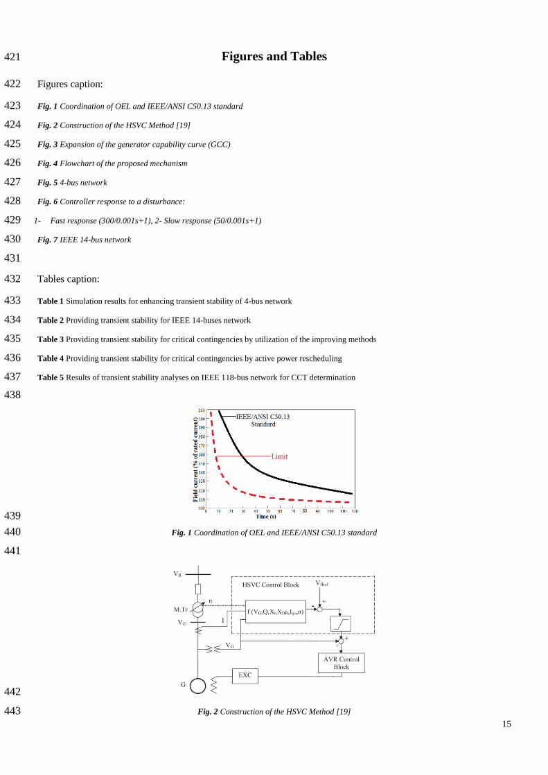
generators rotor winding can support short time overloading. Fig. 1 shows this standard curve which depicts relationship 92
between the excitation current exceeding and acceptable delay for reducing this current. The importance of OEL modelling and 93
its effect on network stability have been discussed in some papers [11-12]. Also, authors in [13] studied the effect of the 94
excitation ceiling voltage ratio on transient stability and experimentally illustrated that increase of excitation ceiling voltage 95
improves transient stability of the system. Therefore, accurate modelling of OEL was studied in some paper and different 96
models were proposed for OEL modelling. 97
An overheating may be occur in rotor winding due to delay of the control equipment, time of heat reduction after field 98
current decreasing, and repeatedly occurrence of overloading [14]. In typical OEL a security margin is considered to protect the 99
synchronous generator from overheating. Fig. 1 shows the margin between actual implementation of OEL (the dotted curve) 100
and IEEE/ANSI C50.13 standard (the solid curve). Reduction of this security margin can increase output power of the 101
generators and enhances the system stability. The authors in [14] proposed an advanced OEL which allows generator to supply 102
power up to its maximum limits by reducing this security margin. In that method, limiting margin of over excitation limiter was 103
estimated base on the field current and voltage measurement of the generator. The authors in [14] explained that the advanced 104
OEL improves stability of the system, also protects generators field winding from overheating. 105
2.2. Controller Response 106
Numerous papers studied excitation system response of synchronous generator and proposed various methods for 107
improving this response. These papers demonstrated that the fast voltage control improves voltage stability, moreover, transient 108
stability of the system. These methods include using PID controller in AVR, using genetic algorithm and fuzzy logic approach 109
for tuning AVR, adjusting the coefficients of the excitation system for achieving better response, and etc [15-17]. 110
Authors in [16] analysed performance of a combined genetic algorithm, radial basis function neural network, and Sugeno 111
fuzzy logic approach for tuning a PID controller for an AVR system and have shown that this method can enhance transient 112
response of the AVR system. Also authors in [17] used linear quadratic Gaussian (LQG) control method for designing a wide 113
area damping controller. Simulation results of [17] have shown that the proposed LQG controller improves inter-area oscillation 114
damping and enhances small signal and transient stability of the system. 115
2.3. High Side Voltage Control 116
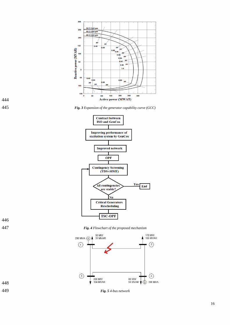
The advanced high side voltage control (HSVC) regulator controls high side voltage of the generator transformer without 117
using direct feedback. Structure and implementation of the HSVC have been obtained by upgrading auxiliary generator 118
Page 5
5
excitation control systems such as line drop compensation (LDC) and the power system voltage regulator (PSVR). HSVC 119
improves voltage stability and enhances rotor angel stability of the system [18]. 120
Authors in [19] studied the effect of HSVC on static voltage stability and damping of oscillation in power systems. Also, 121
HSVC increases loadability of the system [19]. Construction of the advance HSVC is depicted in Fig. 2. 122
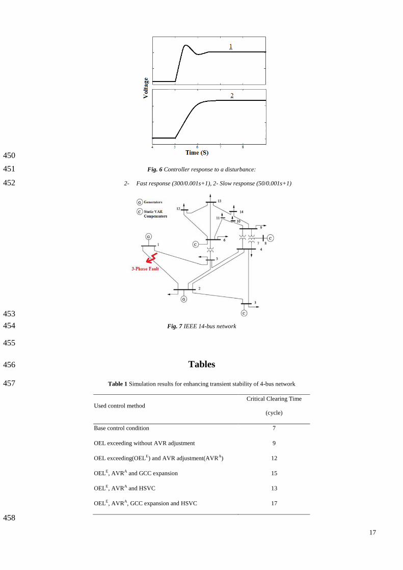
2.4. Expansion of Generator Capability Curve 123
Excess heat from generators must be reduced to keep different components of the generator at predetermined 124
temperatures. Utilization of hydrogen is a common method for cooling the generator in modern power plants. In hydrogen 125
cooling generators, the hydrogen pressure is increased to expand the capability curve of the generator. Similarly, in the cooling 126
air generator, the cooling air temperature is decreased to expand the capability curve of the generator. Fig. 3 shows the 127
expansion of the generator capability curve (GCC) by reducing the cooling air temperature from 46°C to 34°C [20]. Authors in 128
[20] proposed a method in order to modify OEL, under excitation limit (UEL), and other excitation system limits in response to 129
changes in coolant condition such as hydrogen pressure or cooling air temperature. So, expansion of generators capability curve 130
increases their production capacity. 131
132
3. Transient Stability Analysis 133
There are several methods for transient stability analysis which investigate the improving methods effects on transient 134
stability. These methods can be divided into three general categories [21]: time domain simulation, direct method, and hybrid 135
method. Time domain simulation (TDS) method simulates the dynamic behaviour of the system very close to its real operation 136
and allows using detailed model in the simulation [1]. But this method is not able to determine the cause of instability, margin 137
of stability, and design adequate control measures. Also burden of the computation for solving differential equations is 138
weakness of this method [1]. On the other side, direct method limits analysis of power system transient stability to during-fault 139
period, so reduces computation burden. The main problem of this method is system simplification which causes to restrict 140
equipment modelling. Therefore, in this paper hybrid method is used in order to combine advantage of TDS method and direct 141
method. Necessity of the accurate modelling of the system equipments especially generator’s excitation system and over 142
excitation limit causes to use TDS. In addition to this, need to determine critical generators, which cause system instability, and 143
transient stability margin of the system leads to use direct method. 144
In this paper, Single machine equivalent method (SIME) is used to connect TDS method with direct method. In SIME 145
method a multi-machine system is reduced to a two-machine model and then reduced to a one machine infinite bus (OMIB) 146
system [1]. This fact that a multi machine system can be reduced to an OMIB is well known in power system. But earlier 147
methods restrict modelling of the system. The main achievement of SIME method is that any modelling level for large power 148
system can be considered. SIME correlates TDS method with equal area criterion (EAC) and provides very important 149
advantage: identification of critical machines which are responsible for the system instability. 150
Page 6
6
In SIME method a heuristic limit on rotor angle deviation, which is derived from TDS, first identifies critical generators 151
and then two groups of machines can be considered: the critical group and the non-critical group. Afterward, these two groups 152
are converted to a two-machine system, then this two-machine system is reduced to an OMIB by use of (1)-(7). Now, transient 153
stability of the system can be analysed by ECA for the OMIB. The following equations are used to convert a detailed model of 154
power system to an OMIB. A more detailed description of SIME can be found in [1]. 155
NCj
jj
NCCK
KK
C
tMM
tMM
t )(1
)(1
)(
(1) 156
NCj
mj
NCCk
mk
C
m tPM
tPM
MtP )(1
)(1
)(
(2) 157
1 1( ) ( ) ( )e ek ej
k C j NCC NC
P t M P t P tM M
(3) 158
)()()( tPtPtP ema (4) 159
CK
KC MM
(5) 160
NCj
jNC MM
(6) 161
NCC
NCC
MM
MMM
(7) 162
In above equations δj(t) is rotor angle, Pmj (t) is mechanical power, Pej (t) is electrical power, and Mj is inertia coefficient 163
all for generator j. Also δ(t) is rotor angle, Pm (t) is mechanical power, Pe (t) is electrical power, Pa(t) is accelerating power, and 164
M is inertia coefficient of the corresponding OMIB. In these equations subscript C represents critical group and subscript NC 165
represents non-critical group. 166
167
4. Motivation Mechanism for Providing Transient Stability 168
Providing and installing new control equipment has long-term effects on the system, which enhances transient stability 169
of the system. But imposed cost on GenCos due to installing new control equipment discourages these companies from utilizing 170
the improving methods. So, this paper proposes long term contract between ISO and GenCos for providing transient stability of 171
the system. In this contract, ISO first determines required stability margin (required Critical Clearing Time-CCT). Afterward, 172
GenCos undertake to provide this stability margin, and reciprocally ISO pays transient stability providing cost to them. 173
Transient stability providing cost can be determined based on the value of transient stability for ISO, which can be considered 174
as the amount of cost which ISO must pay for providing this stability margin by the other methods (such as change in 175
generators active power). ISO can pay part of this saved cost to GenCos in order to encourage them to utilize the improving 176
methods. Utilization of these methods definitely has a lower cost in compare to the other methods for providing transient 177
Page 7
7
stability. Advanced OEL and HSVC are implemented as software function in a digital AVR like other function of digital AVR 178
such as power system stabilizer (PSS), line drop compensator (LDC), and etc [14]. Controller response improvement can be 179
performed by configuring AVR for better response. Expansion of generator capability curve can be carried out by coordination 180
between limitations and protection functions of excitation system for better cooling operation, so it can be implemented using 181
excitation system functions [20]. Therefore, part of the saved cost due to the use of improving methods can compensate GenCos 182
cost for utilizing these methods. 183
4.1. Procedure of the Proposed Mechanism 184
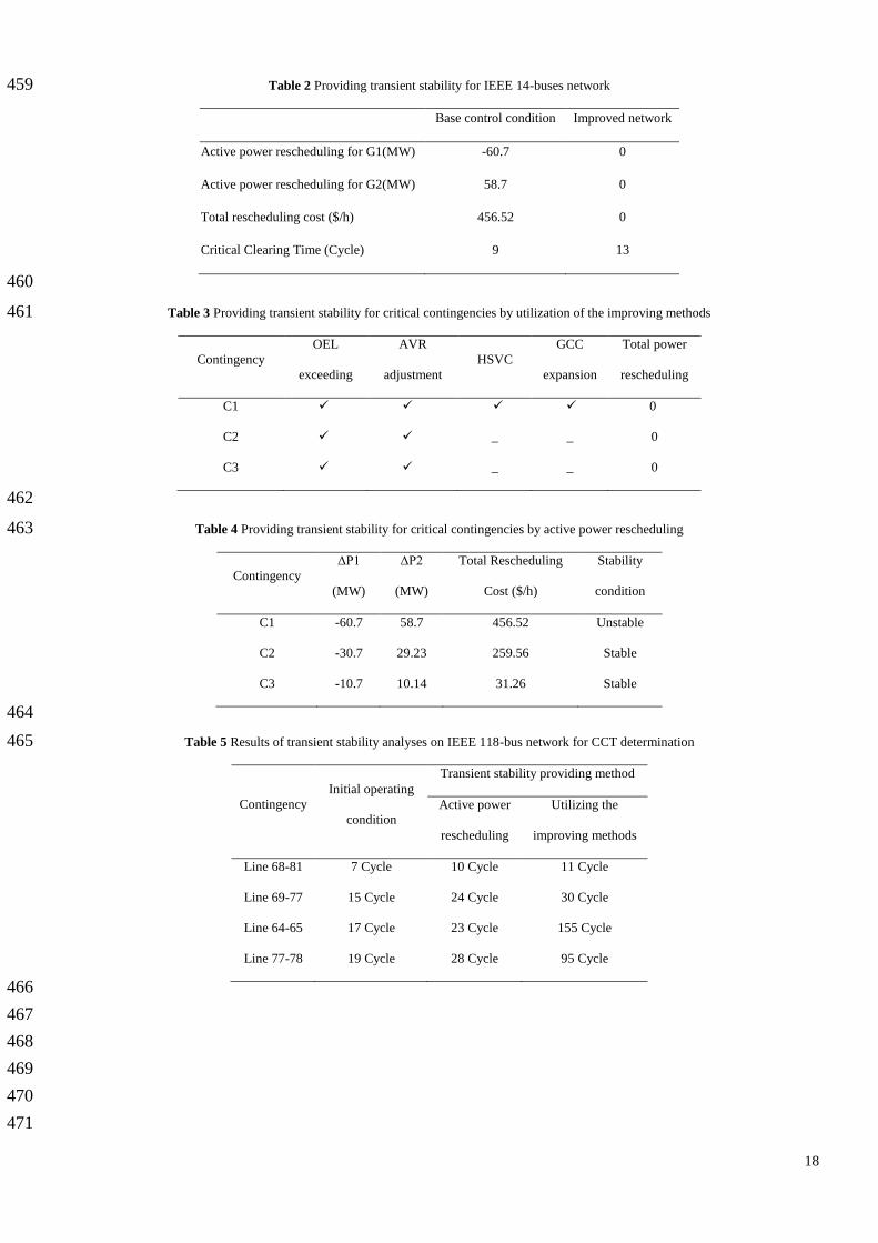
Fig.4 shows flowchart of the proposed mechanism for providing desired transient stability of the system. Step by step 185
implementation procedure of this mechanism is described in the following. 186
1- In the proposed mechanism ISO first contracts with GenCos for providing desired stability margin (Contract 187
between ISO and GenCos). The value of transient stability for ISO determines amount of paid cost to GenCos by 188
ISO. This value depends on several factors such as the importance of transient stability for the system and the cost 189
of transient stability enhancement. 190
2- After contract, GenCos implement the improvement methods which are mentioned in agreement between GenCo 191
and ISO. 192
3- Improved network is the studied network in initial operation point which the improving methods are implemented 193
in excitation systems of generators. 194
4- A conventional OPF is run to determine optimal power flow of the studied network based on GenCos’ bids. In this 195
step, transient stability constraint is not considered. 196
5- Then contingency screening is carried out in the improved network for separation of stable and unstable 197
contingencies. Contingency screening is performed using SIME which was described in [22]. In this method, TDS is 198
carried out for the system and then its results are utilized by SIME in order to evaluate stability condition of 199
contingencies. As utilizing the improving methods enhances transient stability of the system, it is expected that the 200
number of critical contingencies reduces or the number reaches zero. In the case of unstable contingency, critical 201
and non critical generators, stability margin, and operation point of the system are saved and sent to step 7. 202
6- If all of the contingencies are stable the procedure is finished, else transient stability constrained optimal power flow 203
(TSC-OPF) is performed for providing stability in unstable contingencies by rescheduling the critical generators. 204
7- Transient stability of the system can be increased by reducing total active power of critical generators in the 205
network. Equation (8) is used to show the amount of active power which is generated by the critical generators. Pcgi 206
is the amount of active power of each critical generator in the network. P0 is total active power of critical generators 207
in previous scheduling and ΔP is amount of change in active power of critical generators for enhancing transient 208
stability. The critical and the non-critical generators are determined by SIME method. Also, ΔP is determined based 209
Page 8
8
on stability margin by SIME method [1]. 210
PPPCGi
cgi
0
(8) 211
Amount of ΔP is shared between critical generators based on their angular deviation at instability time. In multi 212
unstable contingencies, this ΔP is shared between critical generators which are common in unstable contingencies. 213
More detailed description of critical generators rescheduling can be found in [5]. 214
8- TSC-OPF, which is described in the following section (section 4.2), is run for determining operation point of non 215
critical generators. It should be noted that operation point of the critical generators is determined in step 7. After 216
determining operation point of all generators, the procedure goes back to step 5 to check stability of the system in 217
the new operating condition. 218
4.2. The TSC-OPF Formulation 219
TSC-OPF is used to optimize operation point of the generators in order to providing transient stability of the system. 220
Objective function and constraints are described in the following. Amount of active power of non-critical generators are 221
decision variables. Also cost of active power rescheduling and new schedule of generators are output of this optimization. 222
4.2.1. Objective Function: The purpose of this paper is maintaining system stability with minimum operation cost by 223
utilization of the improving methods. Therefore, objective function of TSC-OPF is minimizing total cost of active power 224
rescheduling. 225
Gi
iPC )(min
(9) 226
4.2.2. Constraints: Equal constraints are production and consumption equality of active and reactive power at each bus 227
in the network. 228
j
jijiijligi VVPPP 0),,,(
(10) 229
j
jijiijligi VVQQQ 0),,,(
(11) 230
Where, Pgi and Qgi are active and reactive power generated at bus i; Pli and Qli are active and reactive power consumed at 231
bus i and Pij and Qij are active and reactive power flow between bus i and bus j. Also Vi and θi are voltage magnitude and 232
voltage angle at bus i. 233
Non-equal constraints in the optimization are: 234
Branch current limits: 235
max),,,( ijjijiij IVVI (12) 236
Bus voltage limits: 237
Page 9
9
maxmin
iii VVV (13) 238
Restriction of active and reactive power in generators: 239
maxmin
gigigi PPP (14) 240
maxmin
gigigi QQQ (15) 241
In this paper, TSC-OPF is only used to ensure providing desired transient stability of the system, while the desired 242
transient stability is not provided by the improving methods (i.e. remained transient stability margin will be supplied trough 243
changing generators’ operation point). In this paper, the method presented in [5] is developed in order to comprise the 244
improving methods in transient stability of the system. In this TSC-OPF, active power of critical generators is shifted to non-245
critical generators for providing transient stability in unstable contingencies. As described, detailed modelling of system 246
equipment cause to use method of [5]. Instead of this method, method of [6] can be used for TSC-OPF which causes to increase 247
complexity of the problem. 248
249
5. Case Study 250
In this section, the proposed mechanism for providing transient stability is analysed. This section has two separate parts. 251
Influence of the improving methods on transient stability is illustrated in first part, while results of the proposed mechanism 252
implementation for providing transient stability are presented in second part. 253
5.1. Effects of the Improving Methods on Transient Stability 254
A 4-bus network, which is shown in Fig. 5, is simulated in MATLAB. Dynamic model of synchronous generator and 255
supplementary equipment (including hydraulic turbine, governor and a ST1 excitation system) are simulated in MATLAB [23]. 256
The OEL model of [11] is used in simulation. Also HSVC is implemented based on model of [19]. 257
To study the effect of improving methods, the dynamic behaviour of the system will be discussed in the presence of a 258
three-phase short circuit in the line between buses 1 and 2. Table 1 shows the effect of improving methods on transient stability 259
of the system. 260
Exceeding of the rated current in excitation system (by using standard ANSI C50.13) causes to improve system transient 261
stability more than 5 cycles. In this situation, network will be stable in the presence of a 12 cycle 3-phase short circuit. To show 262
the impact of AVR controller on transient stability, the coefficients of the controller is configured as shown in Fig. 6. In this 263
figure, the first controller has a fast response, and the second one has a slow response. Concomitant use of standard ANSI 264
C50.13 and fast response controller makes system to be stable over 12 cycles short-circuit. 265
As mentioned, expansion of generator capability curve is another method which affects system transient stability. In this 266
paper, it is assumed that better cooling system of generators increases the output power of generators to 120% of nominal 267
power. The network will be stable over 15 cycles short circuit by considering this assumption and allowing OEL exceeding. 268
Page 10
10
As can be seen in table 1, use of HSVC improves transient stability of the system. Using HSVC along with two other 269
methods makes the system stable over 17 cycle short circuit. This represents 10 cycles improvement in transient stability of the 270
system. 271
5.2. Implementation of the Proposed Mechanism on IEEE 14-bus Network 272
IEEE 14-bus network, which is shown in Fig. 7, is simulated in MATLAB in order to demonstrate the effectiveness of 273
the proposed mechanism in providing transient stability. Dynamic model of the synchronous generators and supplementary 274
equipments (including hydraulic turbine, governor and a ST1 excitation system) are simulated in MATLAB. The OEL model of 275
[11] is used in simulation. Also HSVC is implemented based on model of [19]. The system transient stability is studied in two 276
cases: 277
1- Three-phase fault occurs in transmission lines in order to determine the fault critical clearing time. The worst 278
position of short circuit is the nearest point to generators. 279
2- The second survey is occurrence of single contingency in the network. This event occurs as a tripped line outage 280
after a short circuit (5 cycles after fault occurrence). 281
Studying of Three-phase short circuits near the generators of the network determines that the most likely instability is 282
related to the occurrence of short circuit in line 1 between bus 1 and bus 2. In this situation, the system in base control condition 283
can only sustain short circuit with 4 cycle’s duration. 284
5.2.1 Fault Critical Clearing Time: In order to compare the proposed mechanism for providing transient stability with 285
conventional method, two conditions are considered. In the first condition, it is assumed that GenCos abstain from using the 286
improving methods. Therefore, ISO uses conventional methods for providing transient stability. In this condition, active power 287
of generators is rescheduled to increase stability margin of the system. This condition is called base control condition. The 288
second one, which improving methods are used in all generators of this network, is called improved network. Utilizing of the 289
improving methods provides whole or a part of desired transient stability margin. If the improving methods can not satisfy the 290
desired stability level entirely, change in active power of generators is used as well. 291
Table 2 shows results of transient stability providing for IEEE 14-bus network by conventional method and the 292
proposed mechanism. In this table, amount of active power rescheduling for each one of the generators, total rescheduling cost, 293
and critical clearing time are presented. In the base control condition, transient stability is improved by change in generators 294
operation point. But in the improved network, transient stability is provided by the proposed mechanism of this paper. Change 295
in generators operation point can improve transient stability of the system only 5 cycles. Therefore, this method leads critical 296
clearing time to 9 cycles for the base control condition. However, the proposed mechanism can improve the network transient 297
stability over 9 cycles. So, utilizing the improving methods makes system to be stable for 13 cycle short circuit. Comparing the 298
results indicates that the improving methods not only saves 456 dollar per hour but also improves network transient stability 299
more than the conventional method. 300
Page 11
11
Different methods can be used to enhance transient stability of the system. These methods include excitation system 301
response improving methods [10-20], active power rescheduling [2-8], and FACTS devices installation [24-26]. Performance of 302
the improving methods and active power rescheduling are compared in this paper. Another conventional method for transient 303
stability enhancement is installation of thyristor control series capacitor (TCSC). Transient stability improvement by this 304
method is dependent on location of TCSC installing. For better comparison between the improving methods and conventional 305
methods, a TCSC is installed in line 2 between bus 1 and bus 5. Installing of this TCSC causes to enhance transient stability of 306
the system about 4 cycles. Therefore, the studied network will be stable in the presence of 8 cycle short circuit in the line 1 307
between bus 1 and bus 2. As expected, use of this device has installation cost. This method imposes about 0.3 million dollar 308
cost on ISO per year. This cost is calculated based on (16)-(18) [27]. 309
($/KVAR) SSC TCSCTCSCTCSC 75.153713.00015.0 2 (16) 310
($) SCIC TCSCTCSCTCSC 1000** (17) 311
($/year) ir
irirICAIC
LT
LT
TCSCTCSC1)1(
)1(
(18) 312
In (17) CTCSC is cost of TCSC and STCSC is operating range of TCSC. Investment cost is converted to annual cost by (18). 313
In (18) lifetime (LT) of this equipment is 15 years and interest rate (ir) is 0.05. 314
Installation of TCSC has less cost in compare to rescheduling of active power. If rescheduling of active power imposes 315
456 ($/h) on ISO just for 8 hours in a day (peak time), so this method will impose about 1.3 million dollar cost on ISO per year, 316
while TCSC installation has 0.3 million dollar cost per year. But each one of these two methods has noticeable cost in compare 317
to the improving methods of excitation system. Therefore a part of saved cost due to use of the improving methods (instead of 318
active power rescheduling or TCSC installation) can compensate imposed cost on GenCos for installing and using the 319
improving methods. 320
5.2.2. Single Contingency Analysis: In order to investigate the transient stability of the network in case of single 321
contingency, the method described in [22] is used to screening the contingencies. So, only the events which lead network to 322
instability are examined. In this network, three single contingency will cause network instability. These contingencies include 323
tripped line outage after a 3-phase short circuit with 5 cycle length in lines between bus 1 and bus 2 (C1), between bus 1 and 324
bus 5 (C2), and between buses 2 and bus 5 (C3). 325
Transient stability for these events can be provided by utilizing the improving methods. In occurrence of C1, all of the 326
improving methods (which described in section 2) are needed to provide transient stability of the network. While transient 327
stability for two other events can be provided by using AVR adjustment and OEL exceeding. Table 3 shows the related 328
simulation results. As this table illustrates, utilizing of the improving methods can provide system transient stability and there is 329
no need to rescheduling of the generators. 330
Page 12
12
In order to compare the effectiveness of the proposed mechanism with conventional method, change in generators output 331
is used to enhance transient stability of the network for these critical contingencies. Table 4 shows results of TSC-OPF 332
implementation on base control condition network, which active power rescheduling is used to enhance transient stability of the 333
system instead of the improving methods. In this table, active power rescheduling for each one of two generators, total 334
rescheduling cost, and network stability status after TSC-OPF implementation are represented. As the results illustrate, utilizing 335
of conventional method (active power rescheduling) increases operation cost. In addition to this, active power rescheduling 336
cannot maintain transient stability of the network in the event of C1. 337
5.3. Implementation of the Proposed Mechanism on IEEE 118-bus Network 338
In order to more investigate the proposed mechanism, IEEE 118-bus network is simulated in DigSilent. Simulation 339
results show that this network in the initial operating condition can withstand 7 cycle 3-phase short circuit on transmission line 340
68-81. In initial operating condition, transient stability providing method described in this paper is not utilized and generators 341
operating condition are derived from conventional OPF. In order to enhance transient stability of this system, active power 342
rescheduling is used by TSC-OPF implementation. As it can be seen in table 5, this method causes to enhance transient stability 343
of this system to 10 cycles for 3-phase short circuit fault on transmission line 68-81. Also, the mentioned excitation system 344
response improving methods in this paper are used to increase transient stability of the system. By utilizing the improving 345
method transient stability of the system enhances to 11 cycles for 3-phase short circuit fault on transmission line 68-81. 346
In this network in order to enhance transient stability by active power rescheduling, operation cost of the system will 347
increase $ 301.53 per hour. If this method is needed just for peak time transient stability providing, active power rescheduling 348
increase 880 thousand dollars per year. By comparing implementation results of transient stability providing methods, it is clear 349
that utilizing the improving methods increases transient stability of the system much more than the active power rescheduling. 350
351
6. Conclusion 352
Different control methods were proposed for excitation system response improvement. As the results of this paper 353
illustrated, utilizing the improving methods not only improves transient stability of the system but also decreases network 354
operation cost; whereas conventional methods like as rescheduling of active power of generators may be unable to provide 355
transient stability of the system in some contingencies. But utilizing the improving methods imposes costs on GenCos which 356
discourage them from utilizing these methods. So, this paper proposed a motivation mechanism to encourage GenCos to utilize 357
the improving methods through a long term contract between ISO and GenCos. The proposed mechanism provides the required 358
transient stability margin with minimum cost in compare to the other methods. In this contract, GenCos are payed for utilizing 359
the improving methods in order to provide required transient stability margin for the system. Utilizing the improving methods 360
causes to decrease needs to active power rescheduling for transient stability providing, therefore reduces generators restrictions 361
Page 13
13
for active power generation. So the proposed mechanism will benefit GenCos, also it will reduce network operating costs for 362
providing the required transient stability margin. 363
364
7. References 365
1. Pavella, M., Ernst, D., and Ruiz-Vega, D. “Transient stability of power systems a unified approach to assessment and control”, Kluwer 366
Academic Publishers, (2000). 367
2. Gan, D., Thomas, R.J., and Zimmerman, R.D. “Stability-constrained optimal power flow”, IEEE Trans. Power Syst., 15(2) , pp. 535–368
540, (2000). 369
3. Jiang, Q., and Huang, Z. “An Enhanced Numerical Discretization Method for Transient Stability Constrained Optimal Power Flow”, 370
IEEE Trans. Power Syst., 25(4), pp. 1790-1797, (2010). 371
4. Ye, C.J., and Xiang, H.M. “Multi-Objective Optimal Power Flow Considering Transient Stability Based on Parallel NSGA-II”, IEEE 372
Trans. Power Syst., 30(2), pp. 857-866, (2015). 373
5. Ruiz-Vega, D., and Pavella, M. “A comprehensive approach to transient stability control: Part I—near optimal preventive control”, 374
IEEE Trans. Power Syst., 18(4), pp. 1446-1453, (2003). 375
6. Tu, X., Dessaint, L.A., and Nguyen-Duc, H. “Transient stability constrained optimal power flow using independent dynamic 376
simulation”, IET Gener. Transm. Distrib., 7(3), pp. 244–253, (2013). 377
7. Zerigui, A. Dessaint, L.A., Hannat, R., Ah King, R., and Kamwa, I. “Statistical approach for transient stability constrained optimal 378
power flow” IET Gener. Transm. Distrib., 9(14), pp. 1856–1864, (2015). 379
8. Xu, Y., Dong, Z.Y., Xu, Z., Zhang, R., and Wong, K.P. “Power System Transient Stability-Constrained Optimal Power Flow: A 380
Comprehensive Review”, IEEE Power and Energy Society General Meeting, (2012). 381
9. Sun, Y.Z., Li, X, and Zhao, M. “New Lyapunov function for transient stability analysis and control of power systems with excitation 382
control”, Electric Power Systems Research, Elsevier, 57(2), pp. 123–131, (2001). 383
10. IEEE Std. C50.13, “IEEE standard for cylindrical-rotor 50 Hz and 60 Hz synchronous generators rated 10 MVA and above”, (2006). 384
11. Pajuelo, E., Gokaraju, R., and Sachdev, M.S. “Coordination of over excitation limiter, field over current protection and generator 385
control”, IEEE Power and Energy Society General Meeting, Minneapolis, pp. 1-7, (2010). 386
12. Anagnostou, G., and Pal, B. “Impact of over excitation limiters on the power system stability margin under stressed conditions”, IEEE 387
Trans. on Power Systems, 31(3), pp. 2327-2337, (2016). 388
13. Yang, K., Zeng, Y., Zeng, J., Gao, Q., Wei, W., and Zhao, J. “Experimental studies on transient stability of power ratio of excitation 389
interactions system ceiling voltage systems”, IEEE Tencon, Bali, pp. 913-917, (2011). 390
14. Shimomura, M., Xia, Y., Wakabayashi, M., and Paserba, J. “A new advanced over excitation limiter for enhancing the voltage stability 391
of power systems”, IEEE Power Engineering Society Winter Meeting, Columbus, pp. 221-227, (2001). 392
15. Mohanty, P., Sahu, B., and Panda, S. “Tuning and assessment of proportional–integral–derivative controller for an automatic voltage 393
regulator system employing local unimodal sampling algorithm”, Electric Power Components and Systems, Taylor & Francis, 42(9), pp. 394
959-969, (2014). 395
Page 14
14
16. AlGizi, A.J.H, Mustafa, M.W., Al-geelani, N.A., and Alsaedi, M.A. “Sugeno fuzzy PID tuning, by genetic-neutral for AVR in electrical 396
power generation”, Applied Soft Computing, Elsevier, 28, pp. 226–236, (2015). 397
17. Bhadu, M., Senroy, N., Narayan Kar, I., and Nair Sudha, G. “Robust linear quadratic Gaussian-based discrete mode wide area power 398
system damping controller”, IET Gener. Transm. Distrib., 10(6), pp. 1470–1478, (2016). 399
18. An, J., Huang, G., Mu, G., Zheng, T., and Zhou, Y. “Optimal HSVC Droop Planning for the Voltage Profile Improvements in Bulk 400
Power Systems”, IEEE Power & Energy Society General Meeting, (2015). 401
19. Akbari Foroud, A., Seifi, H., and Khaki Sedigh, A. “Advanced HSVC tuning in multi-machine power systems for loadability 402
improvement”, Electric Power Components and Systems, Taylor & Francis, 34, pp. 689-706, (2006). 403
20. Lawson, R.A., Pearson, W.R., and Curran, J.E. “Method and apparatus for modifying limit and protection software in a synchronous 404
generator exciter to match the capability of the turbine generator”, Patent application publication, US6294898, (2001). 405
21. Kyriakidis, Th., Lanz, G., Cherkaoui, R., and Kayal, M. “A transient stability assessment method using post-fault trajectories”, IEEE 406
PowerTech, Grenoble, pp. 1-4, (2013). 407
22. Erns, D., Ruiz-Vega, D., Pavella, M., Hirsch, P., and Sobajic, D. “A unified approach to transient stability contingency filtering, ranking 408
and assessment”, IEEE Trans. Power Syst., 16(3), pp. 435-443, (2001). 409
23. http://www.mathworks.com/examples/simpower/50-synchronous-machine, accessed 3 June 2015. 410
24. Bakhshi, M., Holakooie, M. H., and Rabiee, A. “Fuzzy based damping controller for TCSC using local measurements to enhance 411
transient stability of power systems”, Electrical Power and Energy Systems, Elsevier, 85, pp. 12–21, (2017). 412
25. Esmaeili Dahej, A., Esmaeili, S., and Goroohi, A. “Multi-objective Optimal Location of SSSC and STATCOM Achieved by Fuzzy 413
Optimization Strategy and Harmony Search Algorithm”, Scientia Iranica D, 20(6), pp. 2024-2035, (2013). 414
26. Ghanizadeh, R., Ebadian, M. , Golkar, M. A., and Jahandideh shendi, A. “Investigating Performance of the New FC-MCR Compensator 415
for Enhancing Power System Stability Using Multi-Objective Imperialist Competitive Algorithm (ICA)”, Scientia Iranica D, 21(6), pp. 416
2200-2212, (2014). 417
27. Wibowo, R.S., Yorino, N., Eghbal, M., Zoka, Y., and Sasaki, Y. “FACTS devices allocation with control coordination considering 418
congestion relief and voltage stability”, IEEE Trans. on Power Systems, 26(4), pp. 2302–2310, (2011). 419
420
Page 15
15
Figures and Tables 421
Figures caption: 422
Fig. 1 Coordination of OEL and IEEE/ANSI C50.13 standard 423
Fig. 2 Construction of the HSVC Method [19] 424
Fig. 3 Expansion of the generator capability curve (GCC) 425
Fig. 4 Flowchart of the proposed mechanism 426
Fig. 5 4-bus network 427
Fig. 6 Controller response to a disturbance: 428
1- Fast response (300/0.001s+1), 2- Slow response (50/0.001s+1) 429
Fig. 7 IEEE 14-bus network 430
431
Tables caption: 432
Table 1 Simulation results for enhancing transient stability of 4-bus network 433
Table 2 Providing transient stability for IEEE 14-buses network 434
Table 3 Providing transient stability for critical contingencies by utilization of the improving methods 435
Table 4 Providing transient stability for critical contingencies by active power rescheduling 436
Table 5 Results of transient stability analyses on IEEE 118-bus network for CCT determination 437
438
439
Fig. 1 Coordination of OEL and IEEE/ANSI C50.13 standard 440
441
442
Fig. 2 Construction of the HSVC Method [19] 443
Page 16
16
444
Fig. 3 Expansion of the generator capability curve (GCC) 445
446
Fig. 4 Flowchart of the proposed mechanism 447
448
Fig. 5 4-bus network 449
Page 17
17
450
Fig. 6 Controller response to a disturbance: 451
2- Fast response (300/0.001s+1), 2- Slow response (50/0.001s+1) 452
453
Fig. 7 IEEE 14-bus network 454
455
Tables 456
Table 1 Simulation results for enhancing transient stability of 4-bus network 457
Used control method
Critical Clearing Time
(cycle)
Base control condition 7
OEL exceeding without AVR adjustment 9
OEL exceeding(OELE) and AVR adjustment(AVRA) 12
OELE, AVRA and GCC expansion 15
OELE, AVRA and HSVC 13
OELE, AVRA, GCC expansion and HSVC 17
458
Page 18
18
Table 2 Providing transient stability for IEEE 14-buses network 459
Base control condition Improved network
Active power rescheduling for G1(MW) -60.7 0
Active power rescheduling for G2(MW) 58.7 0
Total rescheduling cost ($/h) 456.52 0
Critical Clearing Time (Cycle) 9 13
460
Table 3 Providing transient stability for critical contingencies by utilization of the improving methods 461
Contingency
OEL
exceeding
AVR
adjustment
HSVC
GCC
expansion
Total power
rescheduling
C1 0
C2 _ _ 0
C3 _ _ 0
462
Table 4 Providing transient stability for critical contingencies by active power rescheduling 463
Contingency
ΔP1
(MW)
ΔP2
(MW)
Total Rescheduling
Cost ($/h)
Stability
condition
C1 -60.7 58.7 456.52 Unstable
C2 -30.7 29.23 259.56 Stable
C3 -10.7 10.14 31.26 Stable
464
Table 5 Results of transient stability analyses on IEEE 118-bus network for CCT determination 465
Contingency
Initial operating
condition
Transient stability providing method
Active power
rescheduling
Utilizing the
improving methods
Line 68-81 7 Cycle 10 Cycle 11 Cycle
Line 69-77 15 Cycle 24 Cycle 30 Cycle
Line 64-65 17 Cycle 23 Cycle 155 Cycle
Line 77-78 19 Cycle 28 Cycle 95 Cycle
466
467
468
469
470
471
Page 19
19
Biography: 472
Ali Khandani received the B.S. degree in 2009 from Iran University of Science and Technology and 473
the M.Sc. degree in 2012 from Bu-Ali Sina University. He is currently Ph.D. student in Semnan 474
University, Semnan, Iran. His research interests are in the power market, power system optimization, 475
power quality, and power system operation and control. 476
477
478
Asghar Akbari Foroud received the B.S. degree from Tehran University and the M.Sc. and the Ph.D. 479
degrees from Tarbiat Modares University, Tehran, Iran. He became an Assistant Professor in 2006 and an 480
Associate Professor in 2012 at Semnan University. His fields of interest are power system dynamics, 481
operation and control, power market, power system planning, power quality, and power system 482
distribution. 483 484