Provincial Electricity Authority, Thailand 1 Harmonic Assessment of PEA North1, Harmonic Assessment of PEA North1, Chiangmai’s Customers in North Chiangmai’s Customers in North Industrial Estate Industrial Estate Chotepong Pongsriwat. M.Eng(EE) Chief of Power Quality Section PEA (Chiang Mai, THAILAND) 19 - 21 September 2011, Chiang Mai, Thailand PQSynergy TM 2011
Transcript
Provincial Electricity Authority, Thailand 1
Harmonic Assessment of PEA Harmonic Assessment of PEA North1, North1,
Chiangmai’s Customers in North Chiangmai’s Customers in North Industrial EstateIndustrial Estate
Chotepong Pongsriwat. M.Eng(EE) Chief of Power Quality SectionPEA (Chiang Mai, THAILAND)
19 - 21 September 2011, Chiang Mai, Thailand
PQSynergy TM 2011
• Distribution System: 22, 33 kV 289,328 cct-km
• Transmission System: 115 kV 8,701 cct-km
• 99.98% of electrified villages
• 14.60 millions of customer
• 14,089.58 MW of peak load
• 89,602.24 millions of KWhr of sales electricity
Provincial Electricity AuthorityPEA North Area 1,
ChiangMai, Thailand
Provincial Electricity Authority, Thailand 219 - 21 September 2011, Chiang Mai, Thailand
Problems created by harmonics
• Capacitor Problems
Due to its lower impedance, capacitors are even more susceptible to higher order harmonics. If not protected from harmonic stress, a capacitor may fail pretty soon.
19 - 21 September 2011, Chiang Mai, ThailandProvincial Electricity Authority, Thailand 3
19 - 21 September 2011, Chiang Mai, ThailandProvincial Electricity Authority, Thailand 4
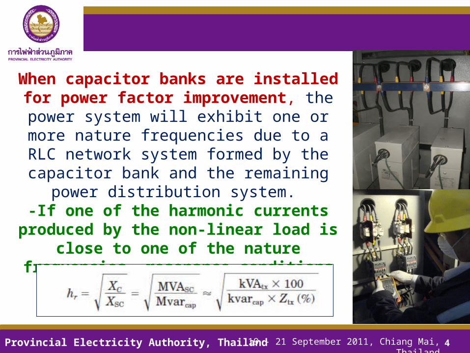
When capacitor banks are installed for power factor improvement, the power system will exhibit one or more nature
frequencies due to a RLC network system formed by the capacitor bank and the remaining power distribution system.
-If one of the harmonic currents produced by the non-linear load is close to one of the nature frequencies, resonance conditions
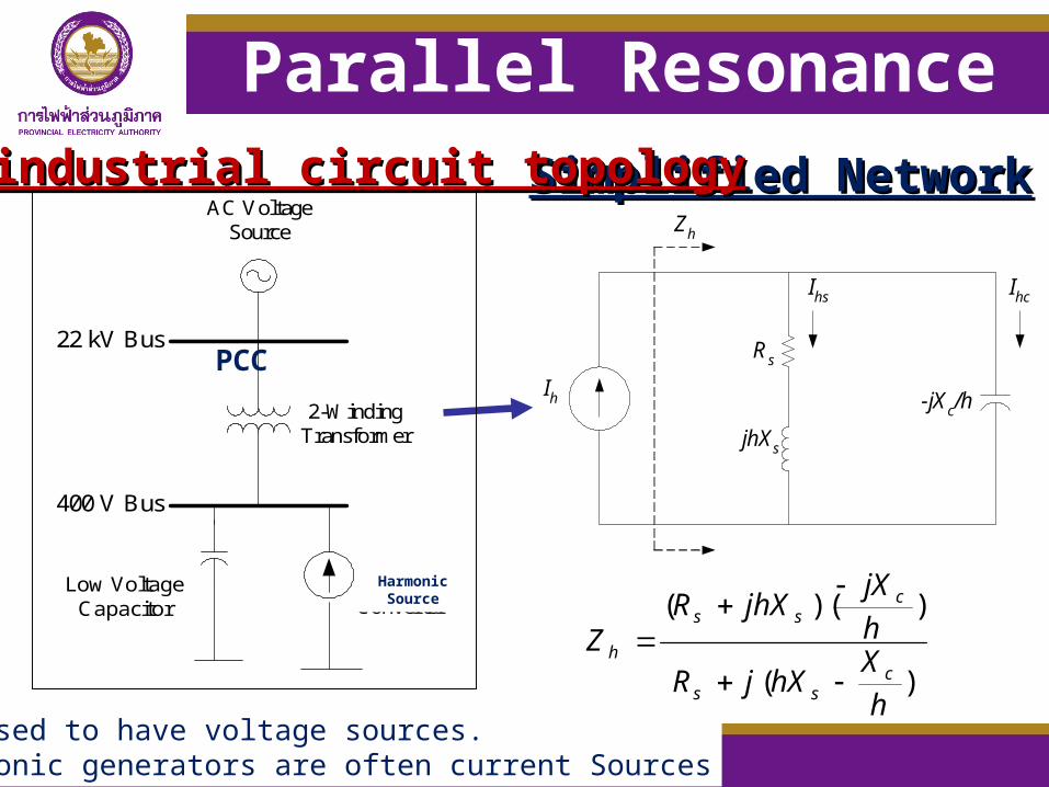
We used to have voltage sources. Harmonic generators are often current Sources
Parallel Resonance (cont’)
jhXs
-jXc/hIh
Rs
Zh
Ihs Ihc
h
XhX c
s
)(
)(
)/(h
XhXjR
IjhXR
hjX
VI
css
hss
c
hhc
)(
)/(
h
XhXjR
IhjX
jhXR
VI
css
hc
ss
hhs
At resonance point :
hs
shc I
R
jhXI
1
hs
chs I
R
hjXI
/
)(h
XhXjR
jhXR
I
IM
css
ss
h
hcc
)(
/
h
XhXjR
hjX
I
IM
css
c
h
hss
Current Amplification
Provincial Electricity Authority, Thailand 19 - 21 September 2011, Chiang Mai, Thailand
Easy evaluation of resonance
• * If the harmonic spectrum exhibits abnormal magnitudes, it is abad sign of harmonic resonance.
• * Typically caused by interaction with Power Factor Correction capacitors.
19 - 21 September 2011, Chiang Mai, ThailandProvincial Electricity Authority, Thailand 7
THDH02
H03H04
H05H06
H07H08
H09H10
H11H12
H13H14
H15
0
5
10
15
20
%
B IHarm (max)
Created with DranView 6.6.3
H5 H7
14.2%13%
LCf
2
1
1000.0802.00604.00406.00208.0010.000 [Hz]
4.0161
3.1749
2.3338
1.4926
0.651
-0.1898
400 V Bus: Network Impedance, Magnitude in Ohm
646.100 Hz 3.809 Ohm
DIg
SIL
EN
T
Resonance Frequency :
At this frequency where the inductive and capacitive reactances are equal, harmonic resonance occurs and the total effective impedance can be very high (parallel resonance) or very low (series resonance) depends on the system configuration.
Provincial Electricity Authority, Thailand 19 - 21 September 2011, Chiang Mai, Thailand
Resonance Point
1000.0802.00604.00406.00208.0010.000 [Hz]
4.0161
3.1749
2.3338
1.4926
0.651
-0.1898
400 V Bus: Network Impedance, Magnitude in Ohm
371.800 Hz 1.272 Ohm
DIg
SIL
EN
T
Case 1:
1000.0802.00604.00406.00208.0010.000 [Hz]
4.0161
3.1749
2.3338
1.4926
0.651
-0.1898
400 V Bus: Network Impedance, Magnitude in Ohm
457.200 Hz 1.916 Ohm
DIg
SIL
EN
T
Case 2:
1000.0802.00604.00406.00208.0010.000 [Hz]
4.0161
3.1749
2.3338
1.4926
0.651
-0.1898
400 V Bus: Network Impedance, Magnitude in Ohm
646.100 Hz 3.809 Ohm
DIg
SIL
EN
T
Case 3:
Case Capacitor Size (% of Transformer
Size)
1 30%
2 20%
3 10%
Provincial Electricity Authority, Thailand
From Simulation
• In the past of Thailand, most medium/low voltage transformer in distribution system have delta/wye ground winding configuration installed with low voltage fixed capacitor which has
defined the reactive power rating (kVAR) equal to 30% of transformer size (kVA) on secondary side of the transformer .
• From this action, harmonic resonance from this capacitor can possibly occur.
Current Amplification
Case Capacitor Size (% of Transformer Size)
1 30%
2 20%
3 10%
Current Amplification
0.01
0.1
1
10
1 5 7 11 13 17 19 23 25
Harmonic Order (h)
Am
plif
icat
ion
(T
imes
)
Mc
Ms
Case 1: Current Amplification
0.1
1
10
1 5 7 11 13 17 19 23 25
Harmonic order (h)
Am
plif
icat
ion
(T
imes
)
Mc
Ms
Case 2:
Current Amplification
0.1
1
10
100
1 5 7 11 13 17 19 23 25
Harmonic order (h)
Am
plif
icat
ion
(T
imes
)
Mc
Ms
Case 3:
Provincial Electricity Authority, Thailand
From Simulation
Changing for 30% rule.
19 - 21 September 2011, Chiang Mai, ThailandProvincial Electricity Authority, Thailand 11
• For a low voltage distribution system with capacitor installed, system response evaluation is useful method in order to get an approximation of the resonance frequency for the system.
• During the resonance condition, some of the capacitor indices may over the limitation if the resonance frequency has the same value or very close to some harmonic order of harmonic current source.
• Noticeably, capacitor installation at 30% of distribution transformer size may lead to have higher rms current in capacitor and exceed the maximum allowable limit recommended by IEEE Std 1036-1992.
Capacitor Limitation
IEEE Std 1036-1992 indicates that the capacitor can be applied continuously within the following limitations, including harmonic components:
a) 180% of rated rms current b) 120% of rated peak voltage c) 110% of rated rms voltage d) 135% of rated reactive power
Provincial Electricity Authority, Thailand
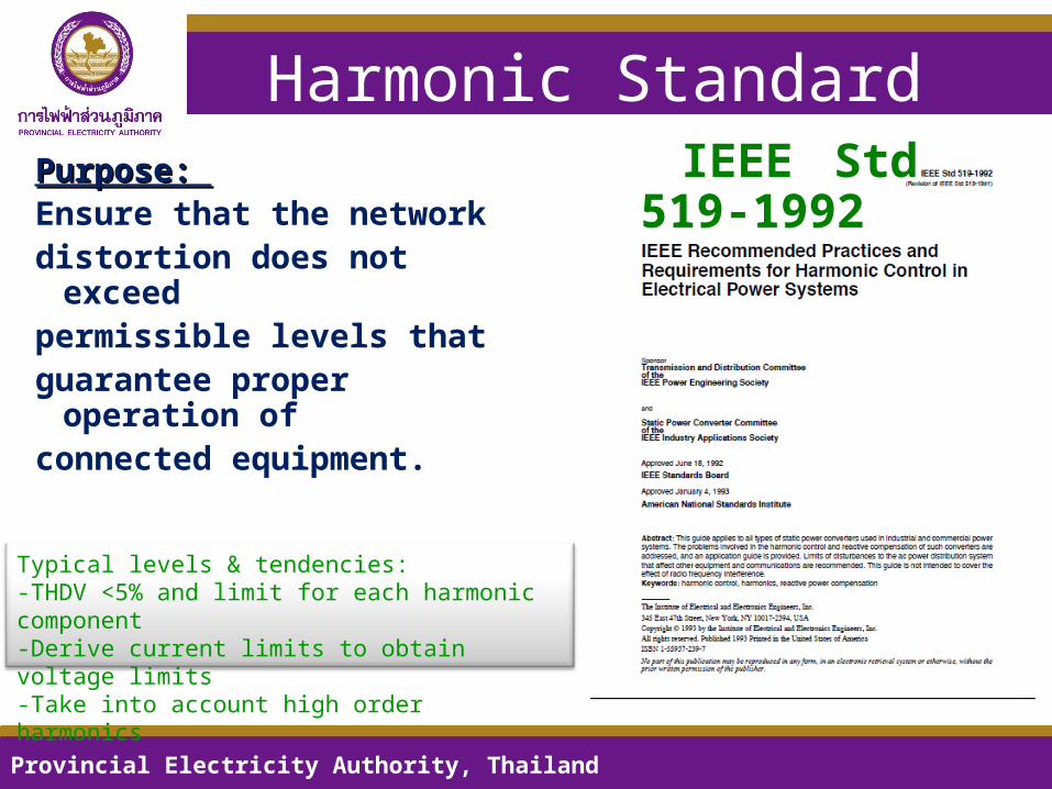
Harmonic StandardPurpose: Purpose: Ensure that the
networkdistortion does not
exceedpermissible levels thatguarantee proper
operation ofconnected equipment.
Provincial Electricity Authority, Thailand
IEEE Std 519-1992
Typical levels & tendencies:-THDV <5% and limit for each harmonic component-Derive current limits to obtain voltage limits-Take into account high order harmonics
Customer Story• Customer specializes in desiging, manufacturing and
servicing high quality galleys, galley & cargo equipment
-Magnetic contactor of switching capacitor used to explodeand they would like to check the quality of power system.
-They would like to eliminate harmonic, if it exists.
After checking, Major problems are
-Most loads are Electronic Ballast,
ASDs(Adjustable Speed Drives), including with anodizing & electropolishing process which run frequently during production process.
-The harmonics are higher than standard
-Capacitor Switching cause high current rate and current magnification
19 - 21 September 2011, Chiang Mai, ThailandProvincial Electricity Authority, Thailand 17
Resonance frequency corresponding to the parameters of the system.
C Bank Step#
f(Hz)Resonance
OrderXL
Resonance
XC Resonance
System Impedance at Fundamantal Frequency
(Ohm)
System Impedance at Resonance Frequency
(Ohm)
11000.20
200.0
01599.6792
015996.792
0008268257 1268.
27072.5
141.4
01131
144
011311.44
0008289018. 634.
35774
7
115
5
00923.5752
009235.752
000830988. 423.
45001.0
100.0
00799.8396
007998.396
0008330845. 317.
54473
0895. 00715.
3983
007153.983
0008351911. 254.
64083.3
81700653.0663
006530.663
0008373081. 211.
73780.4
75600604.6219
006046.219
0008394355. 181.
83536
2707. 00565.
572
005655.72
0008415734. 159.
Frequency Scan
19 - 21 September 2011, Chiang Mai, ThailandProvincial Electricity Authority, Thailand 18
From 400V System
Resonance at 7th HarmonicCapacitors & reactors(transformers) will always create resonance for some frequencies.Resonance is impossible to avoidResonance is not a problem if not excited
System frequency response as capacitor sizeis varied in relation to transformer
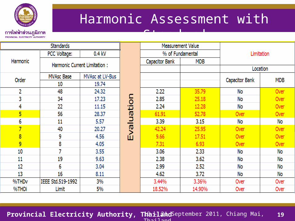
Harmonic Assessment with Standard
19 - 21 September 2011, Chiang Mai, ThailandProvincial Electricity Authority, Thailand 19
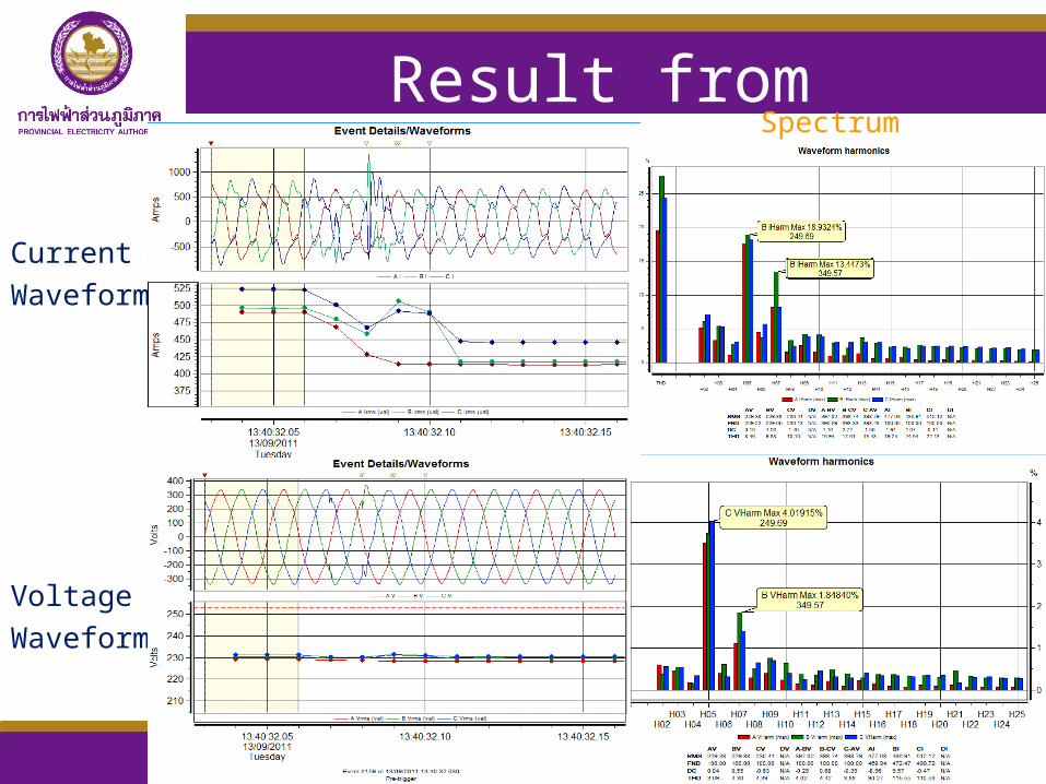
Result from MDB
Current
Waveform
Provincial Electricity Authority, Thailand 20
Voltage
Waveform
Spectrum
Result from Capacitor
Current
Waveform
Provincial Electricity Authority, Thailand 21
Voltage
Waveform
Spectrum
Magnified CurrentIs
Provincial Electricity Authority, Thailand 22
Ic
VcVs
Result : VTHD (Capacitor)
19 - 21 September 2011, Chiang Mai, ThailandProvincial Electricity Authority, Thailand 23
THD Fund Normalized
Result : VTHD (System/Transformer)
19 - 21 September 2011, Chiang Mai, ThailandProvincial Electricity Authority, Thailand 24
THD Fund Normalized
Result : ITHD (Capacitor)
19 - 21 September 2011, Chiang Mai, ThailandProvincial Electricity Authority, Thailand 25
THD Fund Normalized
Result : ITHD (System/Transformer)
19 - 21 September 2011, Chiang Mai, ThailandProvincial Electricity Authority, Thailand 26
THD Fund Normalized
Capacitor Switching• Switching of Capacitor
(Switch off for 1 step)
19 - 21 September 2011, Chiang Mai, ThailandProvincial Electricity Authority, Thailand 27
Ic
Is
Capacitor Switching
19 - 21 September 2011, Chiang Mai, ThailandProvincial Electricity Authority, Thailand 28
• Switching of Capacitor(Switch in for 1 step: step 4 to 5)
Capacitor Switching
• Vpeak of 230V. System = 325.26 V.
19 - 21 September 2011, Chiang Mai, ThailandProvincial Electricity Authority, Thailand 29
• Vpeak = 455.2 V.equal to 1.4 Vpk
(exceed to the limit of rated Vpk, IEEE1026-1992 :1.2 Vpk)
19 - 21 September 2011, Chiang Mai, Thailand
Provincial Electricity Authority, Thailand 30
• All of 8 Capacitors Steps are switched into the system.
Harmonic Assessment with Standard
19 - 21 September 2011, Chiang Mai, ThailandProvincial Electricity Authority, Thailand 31
Suggestions
19 - 21 September 2011, Chiang Mai, ThailandProvincial Electricity Authority, Thailand 32
1. Replace the original magnetic contactor to new type Magnetic contactor with insertion of damping resistor (With Unlimited Peak Current)
2. Detuned Filter Bank 8x50 kVar,400V. 50Hz. 3 phase.
3. Reconsideration, for individual harmonic loads , when new harmonic loads are installed to the system because customer has oftenly add the load without concerning to harmonic.
Thank you very much for your attentions.Thank you very much for your attentions.
19 - 21 September 2011, Chiang Mai, ThailandProvincial Electricity Authority, Thailand 33
Chotepong PongsriwatPQ Chief
SuwipaKittithanapisanPQ Assistant Chief
NatSongkramPQ Engineer
NarusornJan-ngernPQ Engineer
SatidSriwongTechnician
ChinarukKumpromTechnician
Power Quality Team : Chiangmai THAILANDPower Quality Team : Chiangmai THAILANDPower Quality Team : Chiangmai THAILANDPower Quality Team : Chiangmai THAILAND